

Page 1

Philips CMS Patient Monitoring System
Configuration Manual
Anesthesia/Neonatal/Standard
PAD
Part Number M1046-9322L
Printed March 2003
Page 2

Notice
This document contains proprietary information which is protected by
copyright. All Rights Reserved. Reproduction, adaptation, or
translation without prior written permission is prohibited, except as
allowed under the copyright laws.
Philips Medical Systems
Cardiac and Monitoring Systems
3000 Minuteman Road
Andover, MA 01810
+1 (800) 934-7372
Publication number
M1046-9322L
Printed March 2003
Warranty The information contained in this document is subject to change
without notice.
Philips Medical Systems makes no warranty of any kind with regard to
this material, including, but not limited to, the implied warranties or
merchantability and fitness for a particular purpose.
Philips Medical Systems shall not be liable for errors contained herein
or for incidental or consequential damages in connection with the
furnishing, performance, or use of this material. Philips Medical
Systems assumes no responsibility for the use or reliability of its
software on equipment that is not furnished by Philips Medical
Systems.
© 2002 Philips Medizin Systeme Böblingen GmbH
All rights are reserved.
Reproduction in whole or in part is prohibited without the prior
written consent of the copyright holder.
2
Page 3

Printing History
New editions of this document will incorporate all material updated
since the previous edition. Update packages may be issued between
editions and contain replacement and additional pages to be merged
by a revision date at the bottom of the page. Note that pages which are
rearranged due to changes on a previous page are not considered
revised.
The documentation printing date and part number indicate its current
edition. The printing date changes when a new edition is printed.
(Minor corrections and updates which are incorporated at reprint do
not cause the date to change.) The document part number changes
when extensive technical changes are incorporated.
Printing History Overview
Manual Part # Edition Print Date
CMS and NCMS
Edition 1 Dec 1988
Edition 2 May 1989
Edition 3 Feb 1990
Edition 4 Oct 1990
Edition 4 - Revision 1 Oct 1991
Edition 5 Dec 1992
Edition 5 - Revision 1 Feb 1993
Edition 5 - Revision 2 Aug 1993
Edition 6 Jul 1994
Edition 7 Feb 1995
Edition 8 Dec 1995
Edition 9 April 1997
Edition 10 Jan 1998
Edition 11 June 1998
ACMS
Edition 1 Feb 1995
Edition 1 - Revision 1 May 1995
Edition 2 Dec 1995
3
Page 4

Manual Part # Edition Print Date
ACMS
Edition 3 April 1997
Edition 4 Jan 1998
Edition 5 June 1998
CMS, NCMS and ACMS
M1046-9321K
M1046-9321L
M1046-9322L
Edition12 Feb 1999
Edition 13 June 2000
September 2002
4
Page 5

What is in this Manual?
This guide is intended for Biomedical Engineers or Philips Service and
Clinical Specialist personnel who are about to perform the off-line
configuration procedures for the CMS.
What is in this
Manual?
This manual contains information for configuring the CMS at software
Release C.0.
1. Introduction This introduces the concepts of what configuration actually is, why it is
necessary and how best to use it.
2. Procedures This describes the configuration procedure in more detail, explaining
the method by which values are altered.
3. Configuration Tables
This is a detailed list of all the parts of the system that can be
configured. There are tables showing the pre-configured factory values
and all the possible values for every part of the system. A fourth blank
column has been provided for you to record your configuration
changes.
4. Drug
Calculator
Configuration
This chapter lists the standard drugs of the CMS's Drug Calculator
feature. Instructions are given for defining a set of drugs specific to
your unit. A worksheet is included (Appendix B) on which you can
keep a record of the drugs that you configure.
A. Selecting
the Correct
Patient
Category
B. Sign-off
Sheets
C. Printing the
Configuration
This appendix fully details the effects of changing patient category on
the parameters (in particular NBP and ECG) to allow the selection of
the correct category.
This appendix contains a configuration sign-off sheet for recording
who was responsible for making any configuration changes, and a drug
calculator worksheet to document the hospital unit's specific drug
configuration.
This appendix describes how to print screens from the configuration.
5
Page 6

Notation Used
in This Manual
The following symbols are used in this manual:
Hardkey
Represents the keys on the monitor's Control Panel or
Handheld Keypad.
Softkey
Represents the keys in the Task Window.
6
Page 7

Related Documents
Service Guide This manual is a combined reference guide and self-paced course
featuring 7 chapters on how to test, troubleshoot and repair the
instrument. The manual is intended for hospital Biomedical Engineers
and Technicians, Philips Customer Engineers, Response Center
Engineers and Installation Planning Specialists.
Concepts
Guide
This manual provides a conceptual foundation for the monitoring
systems in order to support effective troubleshooting and repair. The
manual is intended for all hospital Biomedical Engineers and
Technicians responsible for troubleshooting, repairing and maintaining
Philips patient monitoring systems.
Site
Preparation
This manual contains the information required for site planning and
installation of the System.
and
Installation
manual
User’s Guide This guide provides operating procedures for the tasks most often
performed on the System.
User’s
This manual comes in 2 volumes:
Reference
Manual
Volu me 1 : Provides detailed reference information on the operation
of the System.
Volu me 2 : Provides detailed reference information on the operation
of Plug-in Modules used with the System.
Quick
Reference
Service Guide
M1234B 21”
Slave Display
Installation &
Service
Manual
This guide provides a brief summary of the important service
information on the System.
This manual provides information on the 21” Slave Display for the
System.
7
Page 8

M1117A Multi-
channel
Thermal Array
Recorder
Service
Manual
This manual provides service and support information for the Philips
M1117A Multi-channel Thermal Array Recorder.
M1032A
VueLink
Handbook
RS232
Computer
Interface
Programming
Guide
Schematics
Book Volume 1
- M1092A/94A
Displays and
DC/DC
Converter
Schematics
Book Volume 2
- Computer
Module and
HIF Devices
This manual provides detailed installation, configuration and service
information specific to the M1032A VueLink (device interface) Module.
This guide provides information on the capabilities of the System's
RS232 Computer Interface, to allow the users (Software Professionals
at medical research clinics or industrial institutions and Biomedical
Engineers) to create applications on PC-based systems.
Volume 1 of the Schematics Book provides schematic diagrams and
parts lists to aid the component level servicing of the M1092A 14”
Monochrome Display, the M1094A 14” Color Display, and the DC/DC
Converter of the System.
Volume 2 of the Schematics Book provides schematic information and
parts lists for the function cards in the Computer Module, and Human
Interface Devices of the System.
Schematics
Book Volume 3
- Plug-In
Modules
Schematics
Book Volume 4
- M1094B
Display
8
Volume 3 of the Schematics Book provides schematic information and
parts lists for the Plug-in Modules of the System.
Volume 4 of the Schematics Book provides schematic diagrams and
parts lists to aid the component level servicing of the M1094B 14” Color
Display.
Page 9

M2003A
Patient Data
Server Service
and
Installation
Guide
This guide provides detailed Installation and Service Information for
the Blood Analysis Interface which is used to transmit Blood Analysis
information from the CMS to a Central Data Station.
M3640A
Central Data
Station Servi ce
and
Installation
Guide
This guide provides detailed Installation and Service Information for
the Central Data Station which can be used to collect and store Blood
Analysis information.
9
Page 10

10
Page 11

Contents
1. Introduction . . . . . . . . . . . . . . . . . . . . . . . . . . . . . . . . . . . . . . . . . . . . . . . . . . . . 15
Configuration Overview . . . . . . . . . . . . . . . . . . . . . . . . . . . . . . . . . . . . . . . . . . . . . . . . . . . 15
What is Configuration Mode? . . . . . . . . . . . . . . . . . . . . . . . . . . . . . . . . . . . . . . . . . . . . 15
Why Configure?. . . . . . . . . . . . . . . . . . . . . . . . . . . . . . . . . . . . . . . . . . . . . . . . . . . . . . . . 15
How Best to Configure?. . . . . . . . . . . . . . . . . . . . . . . . . . . . . . . . . . . . . . . . . . . . . . . . . 15
Configuration Features . . . . . . . . . . . . . . . . . . . . . . . . . . . . . . . . . . . . . . . . . . . . . . . . . . . . 16
Temporary and Permanent Configuration . . . . . . . . . . . . . . . . . . . . . . . . . . . . . . . . . 16
Temporary Configuration Changes . . . . . . . . . . . . . . . . . . . . . . . . . . . . . . . . . . . . 16
Permanent Configuration Changes . . . . . . . . . . . . . . . . . . . . . . . . . . . . . . . . . . . . 16
Universal Set . . . . . . . . . . . . . . . . . . . . . . . . . . . . . . . . . . . . . . . . . . . . . . . . . . . . . . . . . . 17
Configuration Sets . . . . . . . . . . . . . . . . . . . . . . . . . . . . . . . . . . . . . . . . . . . . . . . . . . . . . 18
Global Switches . . . . . . . . . . . . . . . . . . . . . . . . . . . . . . . . . . . . . . . . . . . . . . . . . . . . 18
Parameters. . . . . . . . . . . . . . . . . . . . . . . . . . . . . . . . . . . . . . . . . . . . . . . . . . . . . . . . . 18
Configuration in Monitoring and Service Modes . . . . . . . . . . . . . . . . . . . . . . . . . . 19
Printing the Configuration. . . . . . . . . . . . . . . . . . . . . . . . . . . . . . . . . . . . . . . . . . . . . . . 19
2. Procedures. . . . . . . . . . . . . . . . . . . . . . . . . . . . . . . . . . . . . . . . . . . . . . . . . . . . . . 21
Overview . . . . . . . . . . . . . . . . . . . . . . . . . . . . . . . . . . . . . . . . . . . . . . . . . . . . . . . . . . . . . . . . 21
Entering and Leaving Configuration Mode . . . . . . . . . . . . . . . . . . . . . . . . . . . . . . . . 23
Changing the Configuration Set . . . . . . . . . . . . . . . . . . . . . . . . . . . . . . . . . . . . . . . . . . . . . 24
Changing Values . . . . . . . . . . . . . . . . . . . . . . . . . . . . . . . . . . . . . . . . . . . . . . . . . . . . . . . . . . 25
Change Procedure . . . . . . . . . . . . . . . . . . . . . . . . . . . . . . . . . . . . . . . . . . . . . . . . . . . . . 25
3. Configuration Tables . . . . . . . . . . . . . . . . . . . . . . . . . . . . . . . . . . . . . . . . . . . . . 27
Overview . . . . . . . . . . . . . . . . . . . . . . . . . . . . . . . . . . . . . . . . . . . . . . . . . . . . . . . . . . . . . . . . 27
Universal Settings. . . . . . . . . . . . . . . . . . . . . . . . . . . . . . . . . . . . . . . . . . . . . . . . . . . . . . . . . 28
Alarms Configuration Default Table . . . . . . . . . . . . . . . . . . . . . . . . . . . . . . . . . . . . . . 28
Alarms On/Off Default Table. . . . . . . . . . . . . . . . . . . . . . . . . . . . . . . . . . . . . . . . . . . . . 31
Other Patients (Overview) Default Table . . . . . . . . . . . . . . . . . . . . . . . . . . . . . . . . . . 32
Display Default Tables. . . . . . . . . . . . . . . . . . . . . . . . . . . . . . . . . . . . . . . . . . . . . . . . . . 35
Patient Data Management Default Tables . . . . . . . . . . . . . . . . . . . . . . . . . . . . . . . . . 57
Printer Setting Configuration . . . . . . . . . . . . . . . . . . . . . . . . . . . . . . . . . . . . . . . . . 58
Neonatal Event Review Default Table. . . . . . . . . . . . . . . . . . . . . . . . . . . . . . . . . . . . . 64
oxyCRG Default Table . . . . . . . . . . . . . . . . . . . . . . . . . . . . . . . . . . . . . . . . . . . . . . . . . . 65
Configuration Sets . . . . . . . . . . . . . . . . . . . . . . . . . . . . . . . . . . . . . . . . . . . . . . . . . . . . . . . . 66
Global Switches . . . . . . . . . . . . . . . . . . . . . . . . . . . . . . . . . . . . . . . . . . . . . . . . . . . . . . . 66
Parameter Settings . . . . . . . . . . . . . . . . . . . . . . . . . . . . . . . . . . . . . . . . . . . . . . . . . . . . . . . . 68
Parameter Settings Transfer . . . . . . . . . . . . . . . . . . . . . . . . . . . . . . . . . . . . . . . . . . . . . 68
Restoring Parameter Settings Transfer factory defaults. . . . . . . . . . . . . . . . . . . 68
Heart Rate (HR) / Pulse Default Table. . . . . . . . . . . . . . . . . . . . . . . . . . . . . . . . . . . . . 69
ECG Default Table . . . . . . . . . . . . . . . . . . . . . . . . . . . . . . . . . . . . . . . . . . . . . . . . . . . . . 71
ECG Defaults with EASI™ 12-Lead Option . . . . . . . . . . . . . . . . . . . . . . . . . . . . . . . . 72
Respiration Default Table . . . . . . . . . . . . . . . . . . . . . . . . . . . . . . . . . . . . . . . . . . . . . . . 73
ST Default Table . . . . . . . . . . . . . . . . . . . . . . . . . . . . . . . . . . . . . . . . . . . . . . . . . . . . . . . 74
Pressure Default Tables. . . . . . . . . . . . . . . . . . . . . . . . . . . . . . . . . . . . . . . . . . . . . . . . . 75
Content 11
Page 12

General Pressure Defaults . . . . . . . . . . . . . . . . . . . . . . . . . . . . . . . . . . . . . . . . . . . 75
Pressure Default Alarm Limits . . . . . . . . . . . . . . . . . . . . . . . . . . . . . . . . . . . . . . . . 76
NBP Default Table . . . . . . . . . . . . . . . . . . . . . . . . . . . . . . . . . . . . . . . . . . . . . . . . . . . . . 77
SpO2/SpO2 2/Pleth Default Table. . . . . . . . . . . . . . . . . . . . . . . . . . . . . . . . . . . . . . . . . 79
SvO2 Default Table. . . . . . . . . . . . . . . . . . . . . . . . . . . . . . . . . . . . . . . . . . . . . . . . . . . . . 80
CO2 Default Table . . . . . . . . . . . . . . . . . . . . . . . . . . . . . . . . . . . . . . . . . . . . . . . . . . . . . 81
tcpO2/tcpCO2 Default Table . . . . . . . . . . . . . . . . . . . . . . . . . . . . . . . . . . . . . . . . . . . . . 82
FIO2 Default Table . . . . . . . . . . . . . . . . . . . . . . . . . . . . . . . . . . . . . . . . . . . . . . . . . . . . . 84
Airway Gases . . . . . . . . . . . . . . . . . . . . . . . . . . . . . . . . . . . . . . . . . . . . . . . . . . . . . . . . . 84
Ventilator Configuration Default Table . . . . . . . . . . . . . . . . . . . . . . . . . . . . . . . . . . . 84
7800/7810 Ohmeda Ventilator Configuration Values . . . . . . . . . . . . . . . . . . . . . . 85
7900 Ohmeda Ventilator Configuration Values . . . . . . . . . . . . . . . . . . . . . . . . . . . 86
Cardiac Output Default Table . . . . . . . . . . . . . . . . . . . . . . . . . . . . . . . . . . . . . . . . . . . . 87
Continuous Cardiac Output Default Table . . . . . . . . . . . . . . . . . . . . . . . . . . . . . . . . . 88
EEG Default Table . . . . . . . . . . . . . . . . . . . . . . . . . . . . . . . . . . . . . . . . . . . . . . . . . . . . . 89
Configuring Electrode Montages . . . . . . . . . . . . . . . . . . . . . . . . . . . . . . . . . . . . . . . . . 90
Changing the Items in an Electrode Montage. . . . . . . . . . . . . . . . . . . . . . . . . . . . 90
Temperature Default Table . . . . . . . . . . . . . . . . . . . . . . . . . . . . . . . . . . . . . . . . . . . . . . 91
VueLink Module Default Table . . . . . . . . . . . . . . . . . . . . . . . . . . . . . . . . . . . . . . . . . . . 91
BIS Default Table . . . . . . . . . . . . . . . . . . . . . . . . . . . . . . . . . . . . . . . . . . . . . . . . . . . . . . 92
Differential Temperature Default Table . . . . . . . . . . . . . . . . . . . . . . . . . . . . . . . . . . . 93
CPP Default Table . . . . . . . . . . . . . . . . . . . . . . . . . . . . . . . . . . . . . . . . . . . . . . . . . . . . . 93
Recorder Default Table . . . . . . . . . . . . . . . . . . . . . . . . . . . . . . . . . . . . . . . . . . . . . . . . . 94
Recorder Strip Overlap Choices. . . . . . . . . . . . . . . . . . . . . . . . . . . . . . . . . . . . . . . 97
Procedure Recording Table. . . . . . . . . . . . . . . . . . . . . . . . . . . . . . . . . . . . . . . . . . . 99
Other Recording Configuration Settings . . . . . . . . . . . . . . . . . . . . . . . . . . . . . . . . 99
Configurable Alarm Recordings Default Table. . . . . . . . . . . . . . . . . . . . . . . . . . . . . 100
Blood Analysis Default Table . . . . . . . . . . . . . . . . . . . . . . . . . . . . . . . . . . . . . . . . . . . 102
Output Interfaces . . . . . . . . . . . . . . . . . . . . . . . . . . . . . . . . . . . . . . . . . . . . . . . . . . . . . . . . 104
RS232 Configuration Table . . . . . . . . . . . . . . . . . . . . . . . . . . . . . . . . . . . . . . . . . . . . . 104
First RS232 Card. . . . . . . . . . . . . . . . . . . . . . . . . . . . . . . . . . . . . . . . . . . . . . . . . . . 104
Second RS232 Card . . . . . . . . . . . . . . . . . . . . . . . . . . . . . . . . . . . . . . . . . . . . . . . . 104
Supported RS-232 Configurations . . . . . . . . . . . . . . . . . . . . . . . . . . . . . . . . . . . . 105
Analog Output Default Table . . . . . . . . . . . . . . . . . . . . . . . . . . . . . . . . . . . . . . . . . . . 107
Analog Output Configuration . . . . . . . . . . . . . . . . . . . . . . . . . . . . . . . . . . . . . . . . 113
4. Drug Calculator Configuration . . . . . . . . . . . . . . . . . . . . . . . . . . . . . . . . . . . . 115
Overview . . . . . . . . . . . . . . . . . . . . . . . . . . . . . . . . . . . . . . . . . . . . . . . . . . . . . . . . . . . . . . . 115
Drug Calculator Features . . . . . . . . . . . . . . . . . . . . . . . . . . . . . . . . . . . . . . . . . . . . . . 115
Configuring Drugs . . . . . . . . . . . . . . . . . . . . . . . . . . . . . . . . . . . . . . . . . . . . . . . . . . . . . . . 116
The Worksheet . . . . . . . . . . . . . . . . . . . . . . . . . . . . . . . . . . . . . . . . . . . . . . . . . . . . . . . 116
Drug Change Procedures and Filing in the Worksheet . . . . . . . . . . . . . . . . . . . . . 117
Standard Drug Configuration . . . . . . . . . . . . . . . . . . . . . . . . . . . . . . . . . . . . . . . . . . . . . . 120
A. Selecting the Correct Patient Category . . . . . . . . . . . . . . . . . . . . . . . . . . . . 125
Introduction . . . . . . . . . . . . . . . . . . . . . . . . . . . . . . . . . . . . . . . . . . . . . . . . . . . . . . . . . . . . 125
Factory Default Values . . . . . . . . . . . . . . . . . . . . . . . . . . . . . . . . . . . . . . . . . . . . . . . . 125
12 Contents
Page 13

Changing the Patient Category . . . . . . . . . . . . . . . . . . . . . . . . . . . . . . . . . . . . . . . . . . . . . 126
NBP . . . . . . . . . . . . . . . . . . . . . . . . . . . . . . . . . . . . . . . . . . . . . . . . . . . . . . . . . . . . . . . . . . . 127
Examples . . . . . . . . . . . . . . . . . . . . . . . . . . . . . . . . . . . . . . . . . . . . . . . . . . . . . . . . . . . . 127
Overpressure. . . . . . . . . . . . . . . . . . . . . . . . . . . . . . . . . . . . . . . . . . . . . . . . . . . . . . 127
Continuous Pressure . . . . . . . . . . . . . . . . . . . . . . . . . . . . . . . . . . . . . . . . . . . . . . . 127
NBP - Recommendations. . . . . . . . . . . . . . . . . . . . . . . . . . . . . . . . . . . . . . . . . . . . . . . 129
ECG . . . . . . . . . . . . . . . . . . . . . . . . . . . . . . . . . . . . . . . . . . . . . . . . . . . . . . . . . . . . . . . . . . . 129
Morphology of the ECG. . . . . . . . . . . . . . . . . . . . . . . . . . . . . . . . . . . . . . . . . . . . . . . . 130
Recommendation . . . . . . . . . . . . . . . . . . . . . . . . . . . . . . . . . . . . . . . . . . . . . . . . . . 130
Weak ECG Signal . . . . . . . . . . . . . . . . . . . . . . . . . . . . . . . . . . . . . . . . . . . . . . . . . . . . . 130
Recommendation . . . . . . . . . . . . . . . . . . . . . . . . . . . . . . . . . . . . . . . . . . . . . . . . . . 130
Paced Patients. . . . . . . . . . . . . . . . . . . . . . . . . . . . . . . . . . . . . . . . . . . . . . . . . . . . . . . . 130
Recommendations . . . . . . . . . . . . . . . . . . . . . . . . . . . . . . . . . . . . . . . . . . . . . . . . . 130
Heart Rate (HR) / Pulse . . . . . . . . . . . . . . . . . . . . . . . . . . . . . . . . . . . . . . . . . . . . . . . . 131
Resp . . . . . . . . . . . . . . . . . . . . . . . . . . . . . . . . . . . . . . . . . . . . . . . . . . . . . . . . . . . . . . . . . . . 131
Respiration Suppression Algorithm . . . . . . . . . . . . . . . . . . . . . . . . . . . . . . . . . . . . . . 131
CO2. . . . . . . . . . . . . . . . . . . . . . . . . . . . . . . . . . . . . . . . . . . . . . . . . . . . . . . . . . . . . . . . . . . . 132
B. Sign-Off Sheets . . . . . . . . . . . . . . . . . . . . . . . . . . . . . . . . . . . . . . . . . . . . . . . . 133
Signoff Sheets and Worksheets . . . . . . . . . . . . . . . . . . . . . . . . . . . . . . . . . . . . . . . . . . . . 133
C. Printout of Configuration Information . . . . . . . . . . . . . . . . . . . . . . . . . . . . . 137
Configuration Printout. . . . . . . . . . . . . . . . . . . . . . . . . . . . . . . . . . . . . . . . . . . . . . . . . . . . 137
How to Print Configuration Data . . . . . . . . . . . . . . . . . . . . . . . . . . . . . . . . . . . . . . . . 138
Printing More than One Configuration Screen on a Page . . . . . . . . . . . . . . . . . . . . 138
Contents 13
Page 14

14 Contents
Page 15

Introduction
Configuration Overview
What is Configuration Mode?
Configuration can be thought of as sets of instructions which inform the
CMS about how you want it to work when it is switched on.
Configuration Mode is the operating environment in which you define
these sets of instructions.
WARNING The Configuration Mode does not support patient monitoring:
when the system is attached to a patient, it must be in the
Monitoring Mode.
1
Why Configure?
Configuration of the CMS may be required to suit different hospital
environments (ICU/OR) and patient characteristics (Adult, Neonate or
Pediatric). The grouping of a hospital environment and patient
characteristic is known as a Configuration Set.
The CMS is pre-configured on installation. These pre-configured settings
are known as the Factory Default Values. The pre-configured factory
default values in any of the Configuration Sets can be changed according
to your specific application needs.
How Best to Configure?
The best way to configure the System is to determine and select which
groups of values suit the differing patient categories and hospital
environment types, for example, an Adult, Neonatal or Pediatric
patient in either an OR or ICU environment. With the values grouped in
this way, you do not have to change the ranges for many parameters. For
useful application information on selecting the correct patient category,
refer to Appendix A in this manual.
Configuration Overview 15
Page 16
Introduction
g
Configuration Features
Temporary and Permanent Configuration
The System configuration can be changed temporarily or permanently.
Temporary
Configuration
Changes
Permanent
Configuration
Changes
During normal monitoring (in Monitoring Mode), you can make
temporary alterations to the system configuration to suit a particular
application, without permanently changing the system characteristics.
These temporary changes are known as Active Settings. Any active
settings will be lost when the CMS is:
• Switched off for more than 60 seconds.
• Switched from one Configuration Set to another Configuration Set.
• Switched from one Operating Mode to another Operating Mode.
For more information on which System characteristics can be
configured in Monitoring Mode, refer to the CMS User’s Reference
Manual Volume 1.
Permanent configuration changes are made in Configuration Mode and
stored in the System. If the System is switched off for longer than 60
seconds, the stored configuration will be recalled when the System is
switched on again. Configuration Mode consists of two distinct types of
System Settings:
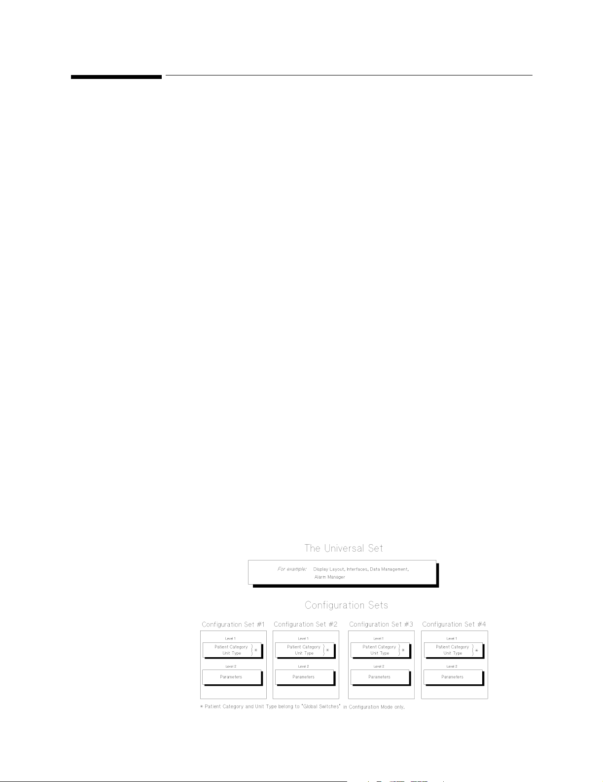
Universal Set to allow the consistent presentation of the patient
information (for example, display layout, alarm
characteristics, etc.), for all configuration sets.
Configuration Sets to control the way the patient parameters are
processed (for example, individual alarm limits).
16 Confi
uration Features
Page 17

Introduction
g
Universal Set
The values in the Universal Set are responsible for those settings that
control, for example, the Display, Alarm Manager, Interfaces, Recorder
Mode, and Patient Data Management. Several Parameters (for example,
Temperature Differential) and configurable items of some Parameters,
are also part of the Universal Set.
NOTE The configurable values of the Unive r sal Set are indepe ndent of, and
unaffected by, the selected Configuration Set.
The following are examples of some of the configurable settings within
the Universal Set:
Display The display settings control the way the patient
information is presented. This includes the color
and wave positioning, speeds etc.
Alarm Manager The Alarm Manager controls the way the alarms
are handled both Latching or Non-latching alarms,
alarms suspended, alarms suspended for 3
minutes, etc.
Interfaces These settings control the way in which the
interfaces are used for connection to a Serial
Distribution Network (SDN), STRIP recorder,
RS232 and Analog Output on CMS and NCMS, or
Serial Distribution Network (SDN), STRIP
recorder, Analog Output and RS232 interface to
the Omheda 7800/7810/7900 Anesthesia Machine
Ventilators, Printer or Personal Computer for the
ACMS.
uration Features 17
Confi
Page 18

Introduction
g
Configuration Sets
There are four Configuration Sets which are used to store information at
two levels. The first level contains information about the patient
category (Neonate, Pediatric or Adult), and hospital environment type
(ICU, OR), collectively known as Global Switches. The second level
contains information about the measured parameters, for example, the
alarm limits for various parameter values.
Global
Switches
This part of the Configuration Set is used to store information about the
patient category and hospital environment type.
Patient Category Changing the Patient Category affects the way the
patient parameter data is processed. For example,
the processing algorithm for ECG is different for
Adults and Neonates.
NOTE Changing the Pati ent Catego ry only changes t he processi ng algor ithm
software for the parameters. The alarm limits, units and bandwidths
are NOT changed automatically. These values must be changed in the
Parameter section of the Configuration Set. This is achieved by
selecting each parameter in turn, and pressing the
Factory Defaults
softkey.
Unit Type (CMS and NCMS only) This is used as a label or
note to remind the person configuring the
parameters in which environment the
Configuration Set is to be used. Certain
parameters, such as the ECG bandwidth, would
normally be different depending upon whether the
environment is ICU or OR.
Note (CMS and NCMS only) Unit Type is only used as a reminder of the
proposed hospital environment so that you make the appropriate
changes in the Parameter section of the Configuration Set. When you
change the Unit Type, you must still change the alarm limi ts, p ara mete r
units and bandwidths.
Parameters This part of the Configuration Set is used to store parameter units,
bandwidths and labels for some of the parameters.
18 Confi
uration Features
Page 19

g
Configuration in Monitoring and Service Modes
The following features of the CMS are configured in either Monitoring or
Service Mode:
Introduction
Feature
Parameter Settings
Transfer
Analog Output Monitoring Model Reference Manual Vol 1
For configuration details on the System's VueLink Module, refer to
Philips M1032A VueLink Module Handbook.
Printing the Configuration
Please refer to Appendix C for details of how printouts of screens of
information can be printed.
Required Mode for
configuration
Service Mode Service Manual Vol 2
Refer to
uration Features 19
Confi
Page 20

Introduction
g
20 Confi
uration Features
Page 21
Procedures
Overview
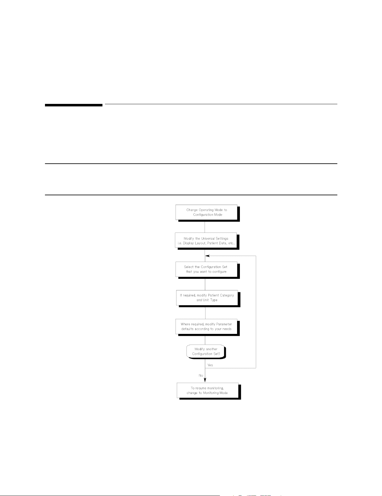
This chapter describes how to change operating modes and how to
make and save changes in Configuration Mode.
NOTE The configuration of the System requires the use of a password. This
is to prevent the configuration being altered either accidentally or by
unauthorized perso nne l .
2
Figure 1 Configuration Procedure Flow diagram
Overview 21
Page 22

Procedures
NOTE If the power fails during configuration, check all the items you have
configured to confirm they have been saved correctly.
22 Overview
Page 23
Procedures
g
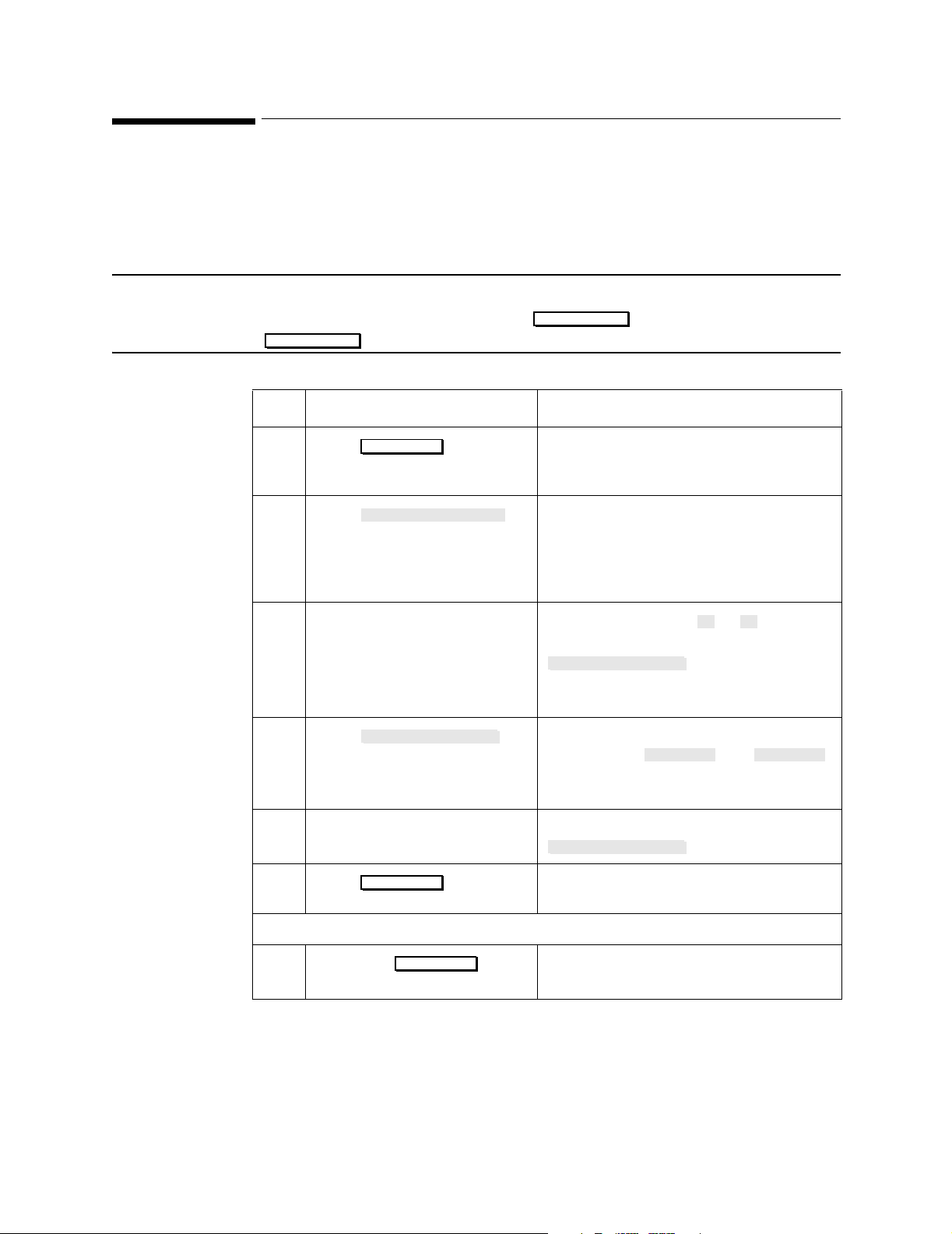
Entering and Leaving Configuration Mode
To start configuring the system, you must select Configuration Mode.
Once you have completed all the changes to the configuration of the
CMS, you must change the operating mode back to Monitoring Mode.
NOTE From Rel. C.0, returning to monitoring mode is allowed without
entering a password. Just press followed by
Resume Monitor
Step Action Comment
.
Monitor Setup
1
Press .
2
Press .
3 Enter the password.
Password: 1245
4
Press .
5 Select the required Opera tin g
Mode.
6
Press .
Monitor Setup
Operating Modes
Change OpMode
Confirm
The Monitor Setup or Instrument
Configuration selection window is
displayed.
The Operating Mode Task Window
displays the current operating mode in
words (for example, “Operating Mode Monitoring”) and prompts for the
password.
Use the keys labeled to . If the
password is correct, then the
Change OpMode
the password is incorrect, the system
returns to the Standard Display.
The Operating Mode Task Window
displays both and
in reverse video, with the current
operating mode highlighted.
Use the arrow keys or press
Change OpMode
The system now performs a cold-start
and switches Operating Modes.
1 5
key is highlighted. If
Monitor Config
.
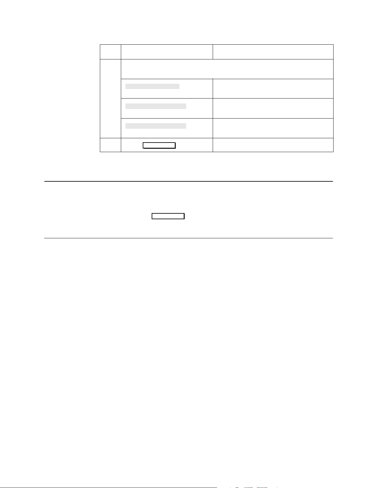
When in Configuration Mode:
7
Press any on
the System.
Hardkey
Pressing a hardkey of your choice allows
you to enter configuration Task Windows.
When Configuration Mode is entered, the display becomes blank and the
message “Config mode active - NO MONITORING!” appears at the top of
the screen.
Enterin
and Leaving Configuration Mode 23
Page 24

Procedures
ging
Changing the Configuration Set
This procedure is used to change the active Configuration Set.
NOTE This procedure can also be performed in Monitoring Mode.
Step Action Comment
1
Press
2
Press .
3 Select the required
configuration set.
4
Press .
Monitor Setup
Config Sets
Confirm
This displays the Monitor Setup or
Instrument Configuration Selection
Window.
This displ ays th e Confi gurat ion S et Task
Window with the current Active
Configuration Set and its Global
Switches.
Use the arrow keys or press
Change ConfSet
The Global Switches for the highlighted
Configuration Set are displayed (for
example, Adult / OR).
To switch to the highlighted
Configuration Set. The system now
performs a cold-start and the chosen
Configuration Set is made Active.
.
After you have selected the new Configuration Set, you can configure
the various items of the Set in Configuration Mode.
24 Chan
the Configuration Set
Page 25

ging
Changing Values
Once you have entered Configuration Mode and made !!active!! the
Configuration Set you wish to alter, then you can make changes to the
values within the active set. Changes to the active set can be made on
two levels:
Global Switches This part of the Configuration Set is used to store
Parameters This part of the Configuration Set is used to store
Change Procedure
The procedure for making any changes is identical. Each set of changes,
for example Global Switches or ECG parameters, have their own Task
Window that displays the possible items that can be changed.
Procedures
Patient Category and Unit Type information as
well as the ECG filtering frequency.
all the parameter settings.
The Task Window displays all the items that can be changed and their
current values. The first item in the Task Window is highlighted. The
procedure to change the values is described in the following steps:
Step Action Comment
1 Select the item you want to
change (for example Patient
Categ).
2
3 The current value is
Press .
highlighted. Highlight the new
value of the item.
Change Content
Use the arrow keys or .
The lower part of the Task Window is
used to display the list of values that can
be used. For example Patient categ
would be:
Adult, Pediatric, Neonate
Use the arrow keys or
Change Content
The value in the upper half of the Task
Window changes accordingly.
Select Item
.
Chan
4 Repeat Steps 1 to 3 for all the items you wish to change in the Task
Window.
Values 25
Page 26
Procedures
ging
Step Action Comment
5 Now you have made the changes to all the items in the Task Window, you
can press:
To save the changes you have made to
the settings.
To recall the previous values for the
settings.
To recall the factory defaults for the
settings.
To confirm your choice.
6
Store Settings
Restore Settings
Factory Defaults
Press
Confirm
NOTE The factory defaults that are recalled will depend on the active Patient
Category and Unit Type of the Configuration Set.
After pressing , do not continue to ope r ate the mon i tor un ti l
Confirm
the prompt message “Active values stored as user defaults” is
displayed.
26 Chan
Values
Page 27

Overview
3
Configuration Tables
This chapter lists the Universal Settings, Configuration Sets, Parameter
Settings and Output Interfaces that can be changed. The content of each
task window is listed in tabular format.
Each table consists of four columns:
• Column one contains the configurable Item Name.
• Column two contains the Factory Default Values.
• Column three lists all the possible values, User Default Values, that
can be selected for each configurable item.
• Column four has been left blank, and can be used for keeping a
record of the items that you configure.
The final page of this chapter is a sign-off sheet which can be used to
record who was responsible for the configuration changes.
Overview 27
Page 28

Configuration Tables
g
Universal Settings
The Universal Settings are generally independent of, and unaffected by,
the Configuration Settings. However, there are some exceptions.
Configurable items of the Universal Settings that are affected by the
Configuration Settings are highlighted in a note accompanying the
appropriate table.
Alarms Configuration Default Table
To access the Alarm information press:
Alarms/Volume Alarms Config
→ .
Factory
Item Name
Default
User Default Values
Values
QRS tone volume 45
Alarm tone vol 120
Prompt tone vol 60 0 to 255 in steps of 15
Alarm Suspend Infinite 1, 2, 3 mins or Infinite
Visual & Audible Latched
Alarm Reminder On On, Off or Re-Alarming (see note below)
Relay sensitive. RedYellow Red, RedYell, RedYell.Inop, Red Inop
QRS type Q RS Tone QRS Tick or QRS Tone
Lowend QRS tone Inaudible Audible or Inaudible
Lowend Al. tone Audible (15) Au dible (15) or Inaudible (0)
Maintn VisualAl No
15 to 255 in steps of 15 or, 0 to 255
15 to 255 in steps of 15, or 0 to 255
Latched, Nonlatched, VisL AudNL
Range (0-255)
Yes or No
note below)
4
(see “Maintain Visual Alarms”
3
User
Configuration
1
2
Reminder Time 3 mins 2 or 3 mins (see “Alarm Reminder” note
below)
1. Dependent on selection of item Lowend QRS. tone.
2. Dependent on selection of item Lowend AL. tone.
3. Visual alarms are latched, audible alarms nonlatched
Central Station acts on visual alarm setting only.
4. If ’Maintn VisualAl’ is set to Yes, all numerics for the active alarming parameters (or
latched alarms) will continue to blink, even if alarms are suspended or the individual
parameter alarm is switched off.
28 Universal Settin
s
Page 29

g
NOTE Maintain Visual Alarms
If Maintn VisualAl is set to Yes, an alarm which has been silence d
and then suspended, will remain silent even if an instrument alarm is
reactivated. To ensure that an alarm continues to sound after it has
been silenced and susp ended, you m ust set the ite m Maint n Vi sualAl
to No.
Note Alarm Reminder
• If the alarm reminder is configured to “On”, an active silenced alarm
will be re-announced (for 6 second s) after the configured Alarm
Reminder Time (temporary acknowledgment).
• If the alarm reminder is configured to “Off”, an active silenced alarm
will not be re-announced (ind efinite acknowledgment).
Configuration Tables
• If the alarm reminder is configured to “Re-Alarming”, an active
silenced alarm will be re-announced after the configured Alarm
Reminder Time has passed. The alarm tone will sound continuously
until it is silenced by pressing the key.
Silence/Reset
Universal Settin
s 29
Page 30

Configuration Tables
g
Note French language CMSs only.
If French Homologation behaviour is required, all settings are
configurable in Service mode under “Global Switches”.
If conforming to these standards, the following alarm configurations
must be selected:
• Prompt tone volume
60 to 255 in steps of 15
• Alarm suspend
3 Min: for a SDN networked environment
Infinite: for a non-SDN networked environment.
Ensure that the monitor’s Alarm Reminder configuration corresponds
to the monitor’s environment.
• Alarm Reminder
• If the alarm reminder is configured to “On”, an active silenced
alarm will be re-annou nced after 2 or 3 minutes (temporary
acknowledgment) (3 minutes for the ACMS).
• If the alarm reminder is configured to “Off”, an active silenced
alarm will not be re-announced (indefinite acknowledgment).
Ensure that the label provided for the monitor corresponds to the
monitor’s configuration for Alarm Remin der.
30 Universal Settin
s
Page 31

g
Alarms On/Off Default Table
Configuration Tables
To access the Alarm information press: → .
Alarms/Volume Alarms On/Off
The table lists all existing features. Availability depends upon the
model or option selected.
Item Name Factory
Default
Values
HR HR
ST-ch1 ST1 On On or Off
ST-ch2 ST2 On On or Off
ST-ch3 ST3 On On or Off
Pulse Pulse On On or Off
Press 1 Any On On or Off
Press 2 Any On On of Off
Press 3 Any On On or Off
Press 4 Any On On or Off
On
1
User Default
Values
On or Off
User
Configura-
tionParameter Label
Press 5 Any On On or Off
Press 6 Any On On or Off
CPP CPP On On or Off
NBP NBP On On or Off
SpO
SpO2 On On or Off
2
SpO
2 SpO2 2 On On or Off
2
On On or Off
ETCO
2
AWRR On On or Off
IMCO
On On or Off
2
FIO
FIO2 On On or Off
2
Resp Resp On On or Off
tcpO
On On or Off
2
On On or Off
tcpCO
2
AG etO
2
AG inO
2
AG ETCO
2
2
2
2
etO2 On On or Off
inO
2
ETCO
2
On On or Off
On On or Off
Universal Settin
s 31
Page 32

Configuration Tables
g
Item Name Factory
Default
Values
AG AWRR
AG IMCO
AG in N
Tblood Tblood On On or Off
Temp 1 T1 On On or Off
Temp 2 T2 On On or Off
Temp 3 T3 On On or Off
Temp 4 T4 On On or Off
CCO CCO On On or Off
BIS BIS On On or Off
2
2
2
2
O
2
1. HR/Pulse alarm exceptions:
• The on/off alarm status for HR and Pulse, cannot be controlled through this
configuration alone. The desired parameter must also be selected in the ‘HR/Pulse
configuration task window’. Without this consistency the required alarm will not be
activated in monitoring mode.
• The above mentioned consistency must also be adhered to if the ‘HR Alarms On/Off’
control has been ‘disabled’.
• If Arrhythmia is assigned, the HR alarm is automatically switched off and pulse is
switched on. The original alarm setting is preserved, and restored, as soon as
arrhythmia is deactivated.
2. ACMS only.
AWRR On On or Off
IMCO
2
in N2O On On or Off
On On or Off
User Default
Values
Configura-
User
tionParameter Label
Other Patients (Overview) Default Table
To access the Other Patient information press:
Other Patients
NOTE Parameters that have more than one wave or numeric will occupy
more than one slot in the priority list. However, they will only appear
once in the broadcast priority list.
WARNING Do not alter the parameter priorities of (2) to (6); only use the
factory default settings.
The table lists all existing features. Availability depends upon the
model or option selected.
32 Universal Settin
. Then the required softkey.
s
Page 33

Configuration Tables
g
Factory
Item Name
Default
User Default Values
Values
Broadcast Parameter: Press: →
Priority #1 ECG ECG
Priority #2 PRESS 1 Do not alter this setting
Priority #3 PRESS 2 Do not alter this setting
Priority #4 PRESS 3 Do not alter this setting
Priority #5 PRESS 4 Do not alter this setting
Priority #6 RESP Do not alter this setting
Priority #7 PLETH Any Parameter
Priority #8 PULSE Any Parameter
Priority #9 SpO
Priority #10 NBP Any Parameter
Priority #11 C.O. Any Parameter
Priority #12 CCO Any Parameter
Priority #13 TEMP 1 Any Parameter
2
Other Patients Broadcst Param
Any Parameter
User
Configuration
Priority #14 TEMP 2 Any Parameter
Priority #15 DIFF 1 Any Parameter
Priority #16 CO
Priority #17 AirwyCO
Priority #18 SvO
Priority #19 FIO
Priority #20 ST Any Parameter
Priority #21 PAWP Any Parameter
Priority #22 CPP Any Parameter
Priority #23 PRESS 5 Any Parameter
Priority #24 PRESS 6 Any Parameter
Priority #25 VueLink B Any Parameter
Priority #26 VueLink B Any Parameter
Priority #27 VueLink B Any Parameter
Priority #28 VentIf Any Parame ter
Priority #28 VueLink A Any Parameter
Any Parameter
2
Any Parameter
2
Any Parameter
2
Any Parameter
2
Universal Settin
Priority #30 VueLink A Any Parameter
Priority #31 tcpO
Any Parameter
2
s 33
Page 34

Configuration Tables
g
Factory
Item Name
Default
User Default Values
Values
Priority #32 tcpCO2 Any Parameter
Priority #33 BIS Any Parameter
Broadcast Parameter: Press: →
Alarm Sensitivity RYI R, RY, RI or RYI
Receive Silenced
Alarms
Yes (see note
below)
Overview Controls: Press: →
1
Extended CareUnit
Group All All, A, B, C, D, E, F, G
Send Alarms Yes Yes or No
Receive Alarms Yes Yes or No
1. This item should only be configured to “Yes” if the monitor is connected to an Extended
CareUnit to avoid unwanted network related malfunction INOPS. For more information, refer to the User’s Reference Manual (Volume 1).
No Yes or No
Other Patients Broadcst Param
Yes or No
Other Patients
Overview Alarms
User
Configuration
Note • Receive Silenced Alarms only has an affect when “Yes” is selected
for Receive Alarms.
• When “Yes” is selected for Receive Silenced Alarms, the Alarm Bed
window will be retained, and the message “Silenced” appears when
the remote alarm is silenced.
• When “No” is selected for Receive Silenced Alarms, the Alarm Bed
window will disappear when the remote alarm is silenced.
The “Show Broadcast” Task Window provides an overview of all current
prioritized parameters that are send over the SDN network. The list is
updated after configuring and storing the settings in the “Broadcast
Parameter” configuration Task Window. press:
Show Broadcst
key to enter the Show Broadcast Task Window.
34 Universal Settin
s
Page 35

g
Display Default Tables
The following tables give the factory default values and the values that
can be selected as user defaults for the display. Separate tables are
provided for the following Models of the CMS and NCMS:
• Model 44(S)
• Model 64(S)
• Model 56(S)
• Model 68(S)
• Model 48(S)
and the following models of the ACMS:
• Model 76(S)
• Model 84(S)
• Model 88(S)
This is followed by the Parameter Display Colors table dedicated to
the colors available for waves on CMS Models 64(S), 68(S), 48(S), and
for the ACMS Model 88(S).
Configuration Tables
The display values are independent of, and unaffected by the chosen
Configuration Set.
NOTE Color assignment is determined by the individual parameter, and can
therefore not be configured for an independent display. See the
Parameter Display Colors table for possible color configurations. All
other User Default Values can be configured for an independent
display.
To make changes to the Display Setup, press:
Monitor Setup Display1 Setup
→ .
To make changes to the Independent Display Setup (if available), press:
Monitor Setup Display2 Setup Display3 Setup
→ or .
To access a different Screen (for example: Screen A, B, C, D or E), press:
Monitor Setup Display1 Setup
→ → Choose Screen.
Universal Settin
s 35
Page 36

Configuration Tables
g
Table 1 CMS Model 44(S) Factory Defaults
(see the Parameter Display Colors Table for color configuration)
Item Name Factory Default Values
Realtime waves
SCREEN A SCREEN B SCREEN C SCREEN D SCREEN E
Channel #1 ECG CH1 ECG CH1 ECG CH1 As Screen C As Screen C
Channel #2 PLETH PLETH PLETH
Channel #3 PRESS 1 PRESS 1 Blank
Channel #4 RESP RESP RESP
Screen Label Standard oxyCRG Standard
Number Of Waves 4 waves 4 waves 4 waves
Overlap #1#1#1
1
Application Window
Wave Replace
2
None oxyCRG Split
Enabled Enabled Enabled
Trace Mode Fixed Fixed Fixed
Numerics Prompt
3
Yes Yes Yes
Realtime speeds:
25mm/s for all except RESP and CO2 (6.25mm/s)
1. OxyCRG and CSA application windows can only be active for one Display at a time. If it
OxyCRG or CSA application windows are chosen for more than one display, it will only
appear on lower number display.
2. If Wave Replace is enabled, CMS will automatically assign measured waves to any
empty channels. Disable this feature if the display configuration should not be changed
when measurements are not available.
3. When “Yes” is selected for this item, the reminder message"Not all numerics displayed"
will appear at the top of the display screen if one or more of the parameter numerics are
switched off.
Numeric On/Off:
Press: → → Choose Screen →
Numeric On/Off
Monitor Setup Display1 Setup
.
If you wish the new setting to be retained after a cold-start has been
performed, press: .
Confirm
36 Universal Settin
s
Page 37

g
Table 2 CMS Model 44(S) User Configuration
(see the Parameter Display Colors Table for color configuration)
Configuration Tables
Item Name
User Default
Values
Realtime waves
Channel #1 Any wave can be assigned
Channel #2
Channel #3
Channel #4
Screen Label Standard, Surgeon,
Number Of Waves 4 Waves
Overlap #1 to #4:
Application Window OxyCRG, Split Screen,
to any channel of 1 to 4
(note number of waves in
Wave Format)
Cardio-vascular, SwanGanz, Neuro-Surgical,
Ventilator, Perfusionist,
Induction, Non-invasive,
User Def., Blank, or any
value typed in on the
numeric keypad.
#1 = non-overlap
#2 = waves 2-3 overlap
#3 = waves 3-4 overlap
#4 = waves 2-4 overlap
CSA Display or None
User Configuration
SCREEN A SCREEN B SCREEN C SCREEN D SCREEN E
Wave Replace Enabled or Disabled
Trace Mode
Numerics Prompt Yes or No
Fixed or Moving
1
Realtime speeds:
6.25, 12.5, 25 or 50 (Each
wave can be configured
separately)
1. It is recommended that you use Fixed Trace Mode for Flatscreen and XGA displays.
Universal Settin
s 37
Page 38

Configuration Tables
g
Table 3 CMS Model 64(S) Factory Defaults
(see the Parameter Display Colors Table for color configuration)
Item Name Factory Default Values
Realtime waves
SCREEN A SCREEN B SCREEN C SCREEN D SCREEN E
Channel #1 ECG CH1 ECG CH1 ECG CH1 ECG CH1 ECG CH1
Channel #2 PRESS 1 PRESS 1 ECG CH2 ECG CH2 ECG CH2
Channel #3 PLETH PRESS 2 PRESS 1 PRESS 1 PRES S 1
Channel #4 RESP PRESS 3 P RES S 2 PRESS 2 PRESS 2
Screen Label Standard Surgeon Surgeon Surgeon Surgeon
Number Of Waves 4 waves 4 waves 4 waves 4 waves 4 waves
Overlap #1#1#3#3#3
1
Application Window
Wave Replace
2
Split Split Split Split Split
Enabled Enabled Enabled Enabled Enabled
Trace Mode Fixed Fixed Fixed Fixed Fixed
Numerics Prompt
3
Yes Yes Yes Yes Yes
Realtime speeds:
25mm/s for all except RESP and CO2 (6.25mm/s)
1. OxyCRG and CSA application windows can only be active for one Display at a time. If it
OxyCRG or CSA application windows are chosen for more than one display, it will only
appear on lower number display.
2. If Wave Replace is enabled, CMS will automatically assign measured waves to any
empty channels. Disable this feature if the display configuration should not be changed
when measurements are not available.
3. When “Yes” is selected for this item, the reminder message"Not all numerics displayed"
will appear at the top of the display screen if one or more of the parameter numerics are
switched off.
Numeric On/Off:
Press: → → Choose Screen →
Numeric On/Off
Monitor Setup Display1 Setup
.
If you wish the new setting to be retained after a cold-start has been
performed, press: .
Confirm
38 Universal Settin
s
Page 39

g
Table 4 CMS Model 64(S) User Configuration
(see the Parameter Display Colors Table for color configuration)
Configuration Tables
Item Name
User Default
Values
Realtime waves
Channel #1 Any wave can be assigned
Channel #2
Channel #3
Channel #4
Screen Label Standard, Surgeon,
Number Of Waves 4 Waves
Overlap #1 to #4:
Application Window OxyCRG, Split Screen,
to any channel of 1 to 4
(note number of waves in
Wave Format)
Cardio-vascular, SwanGanz, Neuro-Surgical,
Ventilator, Perfusionist,
Induction, Non-invasive,
User Def., Blank, or any
value typed in on the
numeric keypad.
#1 = non-overlap
#2 = waves 2-3 overlap
#3 = waves 3-4 overlap
#4 = waves 2-4 overlap
CSA Display or None
User Configuration
SCREEN A SCREEN B SCREEN C SCREEN D SCREEN E
Wave Replace Enabled or Disabled
Trace Mode
Numerics Prompt Yes or No
Fixed or Moving
1
Realtime speeds:
6.25, 12.5, 25 or 50 (Each
wave can be configured
separately)
1. It is recommended that you use Fixed Trace Mode for Flatscreen and XGA displays.
Universal Settin
s 39
Page 40

Configuration Tables
g
Table 5 CMS Model 56(S) Factory Defaults
(see the Parameter Display Colors Table for color configuration)
Item Name Factory Default Values
Realtime waves
SCREEN A SCREEN B SCRE EN C SCREEN D SCREEN E
Channel #1 ECG Ch 1 ECG Ch 1 ECG Ch 1 E CG Ch 1 ECG Ch 1
Channel #2 PRESS 1 ECG Ch 2 ECG Ch 2 ECG Ch 2 PRESS 1
Channel #3 PRESS 2 PRESS 1 PRESS 1 PRESS 1 PRESS 2
Channel #4 PRESS 3 PRESS 2 PRESS 2 PRESS 2 PRESS 3
Channel #5 Pleth PRESS 3 PRESS 3 Pleth Pleth
Channel #6 CO
Screen Label Standard Surgeon Surgeon Standard Standard
Number Of Waves 6 waves 6 waves 6 waves 6 waves 6 waves
Overlap #1
Application Window
Wave Replace
Trace Mode Fixed Fixed Fixed Fixed Fixed
Numerics Prompt
1
2
3
2
(non-overlap)#2(3-5 overlap)#2(3-5 overlap)#1(non-overlap)#1(non-overlap)
Split Split Split Split CSA
Enabled Enabled Enabled Enabled Enabled
Yes Yes Yes Yes Yes
Pleth PRESS 3 CO
2
CO
2
Realtime speeds:
25mm/s for all except RESP and CO2 (6.25mm/s)
1. OxyCRG and CSA application windows can only be active for one Display at a time. If it
OxyCRG or CSA application windows are chosen for more than one display, it will only
appear on lower number display.
2. If Wave Replace is enabled, CMS will automatically assign measured waves to any
empty channels. Disable this feature if the display configuration should not be changed
when measurements are not available.
3. When “Yes” is selected for this item, the reminder message"Not all numerics displayed"
will appear at the top of the display screen if one or more of the parameter numerics
are switched off.
Numeric On/Off:
Press: → → Choose Screen → Press:
Numeric On/Off
Monitor Setup Display1 Setup
.
If you wish the new setting to be retained after a cold-start has been
performed, press: .
40 Universal Settin
Confirm
s
Page 41

g
Table 6 CMS Model 56(S) User Configuration
(see the Parameter Display Colors Table for color configuration)
Configuration Tables
Item Name
User Default
Values
Realtime waves
Channel #1 Any wave can be assigned
Channel #2
Channel #3
Channel #4
Channel #6
Channel #6
Screen Label Standard, Surgeon,
Number Of Waves 4 or 6 Waves
Overlap #1 to #7:
to any channel of 1 to 6
(note number of waves in
Wave Format)
Cardio-vascular, SwanGanz, Neuro-Surgical,
Ventilator, Perfusionist,
Induction, Non-invasive,
User Def., Blank, or any
value typed in on the
numeric keypad.
#1 = non-overlap
#2 = waves 3-5 overlap
#3 = waves 3-6 overlap
#4 = waves 2-5 overlap
#5 = waves 2-6 overlap
#5 = waves 2-3/4-5 overlap
#7 = waves 3-4/5-6 overlap
User Configuration
SCREEN A SCREEN B SCREEN C SCREEN D SCREEN E
Application Window OxyCRG, Split Screen,
Wave Replace Enabled or Disabled
Trace Mode
Numerics Prompt Yes or No
CSA Display or None
Fixed or Moving
1
Realtime speeds:
6.25, 12.5, 25 or 50 (Each
wave can be configured
separately)
1. It is recommended that you use Fixed Trace Mode for Flatscreen and XGA displays.
Universal Settin
s 41
Page 42

Configuration Tables
g
Table 7 CMS Model 68(S) Factory Defaults
(see the Parameter Display Colors Table for color configuration)
Item Name Factory Default Values
Realtime waves
SCREEN A SCREEN B SCREEN C SCREEN D SCREEN E
Channel #1 ECG CH1 ECG CH1 ECG CH1 ECG CH1 ECG CH1
Channel #2 PRESS 1 ECG CH2 ECG CH2 ECG CH2 PRESS 1
Channel #3 PRESS 2 PRESS 1 PRESS 1 PRESS 1 PRESS 2
Channel #4 PRESS 3 PRESS 2 PRESS 2 PRESS 2 PRESS 3
Channel #5 PRESS 4 PRESS 3 PRESS 3 PRESS 3 PRESS 4
Channel #6
Channel #7 PLETH PLETH
Channel #8 RESP CO
PRESS5
1
PRESS 4 PRESS 4 PRESS 4 CO
1
PRESS5
2
PRESS6
PLETH EEG CH1
1
CO
2
EEG CH2
2
Screen Label Standard Surgeon Surgeon Standard Neuro
Number Of Waves 8 waves 8 waves 8 waves 8 waves 8 waves
Overlap #1
Application Window
Wave Replace
Trace Mode Fixed Fixed Fixed Fixed Fixed
Numerics Prompt
3
4
(non-overlap)#2(3-6 overlap)#2(3-6 overlap)#1(non-overlap)#1(non-overlap)
2
Split Split Split Split CSAt
Enabled Enabled Enabled Enabled Enabled
Yes Yes Yes Yes Yes
Realtime speeds:
25mm/s for all except RESP and CO2 (6.25mm/s)
1. For model 48(S) the factory default is BLANK.
2. OxyCRG and CSA application windows can only be active for one Display at a time. If it
OxyCRG or CSA application windows are chosen for more than one display, it will only
appear on lower number display.
3. If Wave Replace is enabled, CMS will automatically assign measured waves to any
empty channels. Disable this feature if the display configuration should not be changed
when measurements are not available.
4. When “Yes” is selected for this item, the reminder message"Not all numerics displayed"
will appear at the top of the display screen if one or more of the parameter numerics are
switched off.
Numeric On/Off:
Press: → → Choose Screen →
Numeric On/Off
start has been performed, press: .
42 Universal Settin
Monitor Setup Display1 Setup
. If you wish the new setting to be retained after a cold-
Confirm
s
Page 43

g
Table 8 CMS Model 68(S) User Configuration
(see the Parameter Display Colors Table for color configuration)
Configuration Tables
Item Name
User Default
Values
Realtime waves
Channel #1 Any wave can be assigned
Channel #2
Channel #3
Channel #4
Channel #5
Channel #6
Channel #7
Channel #8
Screen Label Standard, Surgeon,
Number Of Waves 4, 6 or 8 Waves
to any channel of 1 to 8
(note number of waves in
Wave Format)
Cardio-vascular, SwanGanz, Neuro-Surgical,
Ventilator, Perfusionist,
Induction, Non-invasive,
User Def., Blank, or any
value typed in on the
numeric keypad.
User Configuration
SCREEN A SCREEN B SCREEN C SCREEN D SCREEN E
Overlap #1 to #8:
Application Window OxyCRG, Split Screen,
Wave Replace Enabled or Disabled
Trace Mode
Numerics Prompt
#1 = non-overlap
#2 = waves 3-6 overlap
#3 = waves 3-8 overlap
#4 = waves 2-7 overlap
#5 = waves 4-7 overlap
#5 = waves 3-5/6-8 overlap
#7 = waves 2-4/5-7 overlap
#8 = waves 3-4/5-6 overlap
CSA Display or None
Fixed or Moving
2
Yes or No
1
Realtime speeds:
6.25, 12.5, 25 or 50 (Each
wave can be configured
separately)
1. It is recommended that you use Fixed Trace Mode for Flatscreen and XGA displays.
2. When “Yes” is selected for this item, the reminder message"Not all numerics displayed" will appear at the top of
the display screen if one or more of the parameter numerics are switched off.
Universal Settin
s 43
Page 44

Configuration Tables
g
Table 9 NCMS Model 48(S) Factory Defaults
(see the Parameter Display Colors Table for color configuration)
Item Name Factory Default Values
Realtime waves
SCREEN A SCREEN B SCREEN C SCREEN D SCREEN E
Channel #1 ECG CH1 ECG CH1 ECG CH1 As Screen C As Screen C
Channel #2 PLETH PLETH PLETH
Channel #3 Blank PRESS 1 PLETH 2
Channel #4 PRESS 1 PRESS 2 PRESS 1
Channel #5 PRESS 2 PRESS 3 Blank
Channel #6 PRESS 3 Blank Blank
Channel #7 Blank Blank Blank
Channel #8 RESP RESP RESP
Screen Label Standard Surgeon Surgeon
Number Of Waves 8 waves 8 waves 8 waves
Overlap #1
Application Window
Wave Replace
Trace Mode Fixed Fixed Fixed
Numerics Prompt
2
3
(non-overlap)#1(non-overlap)#1(non-overlap)
1
None OxyCRG Split
Enabled Enabled Enabled
Yes Yes Yes
Realtime speeds:
25mm/s for all except RESP and CO2 (6.25mm/s)
1. OxyCRG and CSA application windows can only be active for one Display at a time. If it
OxyCRG or CSA application windows are chosen for more than one display, it will only
appear on lower number display.
2. If Wave Replace is enabled, CMS will automatically assign measured waves to any
empty channels. Disable this feature if the display configuration should not be changed
when measurements are not available.
3. When “Yes” is selected for this item, the reminder message"Not all numerics displayed"
will appear at the top of the display screen if one or more of the parameter numerics are
switched off.
Numeric On/Off:
Press: → → Choose Screen →
Numeric On/Off
start has been performed, press: .
44 Universal Settin
Monitor Setup Display1 Setup
. If you wish the new setting to be retained after a cold-
Confirm
s
Page 45

g
Table 10 NCMS Model 48(S) User Configuration
(see the Parameter Display Colors Table for color configuration)
Configuration Tables
Item Name
User Default
Values
Realtime waves
Channel #1 Any wave can be assigned
Channel #2
Channel #3
Channel #4
Channel #5
Channel #6
Channel #7
Channel #8
Screen Label Standard, Surgeon,
Number Of Waves 4, 6 or 8 Waves
to any channel of 1 to 8
(note number of waves in
Wave Format)
Cardio-vascular, SwanGanz, Neuro-Surgical,
Ventilator, Perfusionist,
Induction, Non-invasive,
User Def., Blank, or any
value typed in on the
numeric keypad.
User Configuration
SCREEN A SCREEN B SCREEN C SCREEN D SCREEN E
Overlap #1 to #8:
Application Window OxyCRG, Split Screen,
Wave Replace Enabled or Disabled
Trace Mode
Numerics Prompt
#1 = non-overlap
#2 = waves 3-6 overlap
#3 = waves 3-8 overlap
#4 = waves 2-7 overlap
#5 = waves 4-7 overlap
#5 = waves 3-5/6-8 overlap
#7 = waves 2-4/5-7 overlap
#8 = waves 3-4/5-6 overlap
CSA Display or None
Fixed or Moving
2
Yes or No
1
Realtime speeds:
6.25, 12.5, 25 or 50 (Each
wave can be configured
separately)
1. It is recommended that you use Fixed Trace Mode for Flatscreen and XGA displays.
2. When “Yes” is selected for this item, the reminder message"Not all numerics displayed" will appear at the top of
the display screen if one or more of the parameter numerics are switched off.
Universal Settin
s 45
Page 46

Configuration Tables
g
Table 11 ACMS Model 84(S) Factory Defaults
(see the Parameter Display Colors Table for color configuration)
Item Name Factory Default Values
Realtime waves
SCREEN A SCREEN B SCREEN C SCREEN D SCREEN E
Channel #1 ECG CH1 ECG CH1 ECG CH1 As Screen C As Screen C
Channel #2 PRESS 1 PRESS 1 PRESS 1
Channel #3 PLETH PRESS 2 PRESS 2
Channel #4 RESP PRESS 3 AG CO
Screen Label Standard Surgeon Blank
Number Of Waves 4 waves 4 waves 4 waves
Overlap #1
Application Window
Wave Replace
Trace Mode Fixed Fixed Fixed
Numerics Prompt
2
3
(non-overlap)#2(3-5 overlap)#2(2-3 overlap)
1
Split Split Split
Enabled Enabled Enabled
Yes Yes Yes
2
Realtime speeds:
25mm/s for all except:
RESP, CO
1. OxyCRG and CSA application windows can only be active for one Display at a time. If it
OxyCRG or CSA application windows are chosen for more than one display, it will only
appear on lower number display.
2. If Wave Replace is enabled, CMS will automatically assign measured waves to any
empty channels. Disable this feature if the display configuration should not be changed
when measurements are not available.
3. When “Yes” is selected for this item, the reminder message"Not all numerics displayed"
will appear at the top of the display screen if one or more of the parameter numerics are
switched off.
, AG O2, AG CO2, AG Agent (6.25mm/s)
2
Numeric On/Off:
Press: → → Choose Screen →
Numeric On/Off
Monitor Setup Display1 Setup
.
If you wish the new setting to be retained after a cold-start has been
performed, press: .
46 Universal Settin
Confirm
s
Page 47

g
Table 12 ACMS Model 84(S) User Configuration
(see the Parameter Display Colors Table for color configuration)
Configuration Tables
Item Name
User Default
Values
Realtime waves
Channel #1 Any wave can be assigned
Channel #2
Channel #3
Channel #4
Channel #5
Channel #6
Screen Label Standard, Surgeon,
Number Of Waves 4 or 6 Waves
Overlap #1 to #7:
to any channel of 1 to 6
(note number of waves in
Wave Format)
Cardio-vascular, SwanGanz, Neuro-Surgical,
Ventilator, Perfusionist,
Induction, Non-invasive,
User Def., Blank, or any
value typed in on the
numeric keypad.
#1 = non-overlap
#2 = waves 3-5 overlap
#3 = waves 3-6 overlap
#4 = waves 2-5 overlap
#5 = waves 2-6 overlap
#5 = waves 2-3/4-5 overlap
#7 = waves 3-4/5-6 overlap
User Configuration
SCREEN A SCREEN B SCREEN C SCREEN D SCREEN E
Application Window OxyCRG, Split Screen,
Wave Replace Enabled or Disabled
Trace Mode
Numerics Prompt Yes or No
CSA Display or None
Fixed or Moving
1
Realtime speeds:
6.25, 12.5, 25 or 50 (Each
wave can be configured
separately)
1. It is recommended that you use Fixed Trace Mode for Flatscreen and XGA displays.
Universal Settin
s 47
Page 48

Configuration Tables
g
Table 13 ACMS Model 76(S) Factory Defaults
(see the Parameter Display Colors Table for color configuration)
Item Name Factory Default Values
Realtime waves
SCREEN A SCREEN B SCREEN C SCREEN D SCREEN E
Channel #1 ECG CH1 ECG CH1 ECG CH1 ECG CH1 ECG CH1
Channel #2 PRESS 1 ECG CH2 PRESS 1 ECG CH2 PRESS 1
Channel #3 PLETH PRESS 1 PRESS 2 PRESS 1 PRES S 2
Channel #4 AG CO
Channel #5 Blank PRESS 3 Blank PLETH EEG CH2
Channel #6 Blank AG CO
Screen Label Standard Cardio-
Number Of Waves 6 waves 6 waves 6 waves 6 waves 6 waves
Overlap #1
Application Window
Wave Replace
Trace Mode Fixed Fixed Fixed Fixed Fixed
Numerics Prompt
1
2
3
2
(non-overlap)#2(3-5 overlap)#2(3-5 overlap)#1(non-overlap)#1(non-overlap)
Split Split Split Split CSA
Enabled Enabled Enabled Enabled Enabled
Yes Yes Yes Yes Yes
PRESS 2 Blank PRESS 2 EEG CH1
Vascular
2
AG CO
2
Swan-Ganz Standard Neuro
AG CO
2
AG CO
2
Realtime speeds:
25mm/s for all except:
RESP, CO
1. OxyCRG and CSA application windows can only be active for one Display at a time. If it
OxyCRG or CSA application windows are chosen for more than one display, it will only
appear on lower number display.
2. If Wave Replace is enabled, CMS will automatically assign measured waves to any
empty channels. Disable this feature if the display configuration should not be changed
when measurements are not available.
3. When “Yes” is selected for this item, the reminder message"Not all numerics displayed"
will appear at the top of the display screen if one or more of the parameter numerics are
switched off.
, AG O2, AG CO2, AG Agent (6.25mm/s)
2
Numeric On/Off:
Press: → → Choose Screen →
Numeric On/Off
Monitor Setup Display1 Setup
.
If you wish the new setting to be retained after a cold-start has been
performed, press: .
48 Universal Settin
Confirm
s
Page 49

g
Table 14 ACMS Model 76(S) User Configuration
(see the Parameter Display Colors Table for color configuration)
Configuration Tables
Item Name
User Default
Values
Realtime waves
Channel #1 Any wave can be assigned
Channel #2
Channel #3
Channel #4
Channel #5
Channel #6
Screen Label Standard, Surgeon,
Number Of Waves 4 or 6 Waves
Overlap #1 to #7:
to any channel of 1 to 6
(note number of waves in
Wave Format)
Cardio-vascular, SwanGanz, Neuro-Surgical,
Ventilator, Perfusionist,
Induction, Non-invasive,
User Def., Blank, or any
value typed in on the
numeric keypad.
#1 = non-overlap
#2 = waves 3-5 overlap
#3 = waves 3-6 overlap
#4 = waves 2-5 overlap
#5 = waves 2-6 overlap
#5 = waves 2-3/4-5 overlap
#7 = waves 3-4/5-6 overlap
User Configuration
SCREEN A SCREEN B SCREEN C SCREEN D SCREEN E
Application Window OxyCRG, Split Screen,
Wave Replace Enabled or Disabled
Trace Mode
Numerics Prompt Yes or No
CSA Display or None
Fixed or Moving
1
Realtime speeds:
6.25, 12.5, 25 or 50 (Each
wave can be configured
separately)
1. It is recommended that you use Fixed Trace Mode for Flatscreen and XGA displays.
Universal Settin
s 49
Page 50

Configuration Tables
g
Table 15 ACMS Model 88(S) Factory Defaults
(see the Parameter Display Colors Table for color configuration)
Item Name Factory Default Values
Realtime waves
SCREEN A SCREEN B SCRE EN C SCREEN D SCREEN E
Channel #1 ECG CH1 ECG CH1 ECG CH1 ECG CH1 ECG CH1
Channel #2 ECG CH2 ECG CH2 PRESS 1 ECG CH2 PRESS 1
Channel #3 PRESS 1 PRESS 1 PRESS 2 PRESS 1 PRESS 2
Channel #4 PRESS 2 Blank Blank PRESS 2 PRESS 3
Channel #5 PRESS 3 PRESS 2 Blank PRESS 3 PRESS 4
Channel #6 PLETH PRESS 3 Blank PRESS 4 AG CO
Channel #7 AG Agent PLETH PLETH PLETH EEG CH1
Channel #8 AG CO
Screen Label Standard Cardio-
Number Of Waves #1
Overlap #1#2#3#3#3
Application Window
Wave Replace
Trace Mode Fixed Fixed Fixed Fixed Fixed
Numerics Prompt
1
2
3
2
(non-overlap)
Split Split Split Split Split
Enabled Enabled Enabled Enabled Enabled
Yes Yes Yes Yes Yes
AG CO
2
Vascular
#8 (3-4/5-6
overlap)
AG CO
2
Swan-Ganz Standard Neuro
#2
(3-5 overlap)#1(non-overlap)#1(non-overlap)
AG CO
2
2
EEG CH2
Realtime speeds:
25mm/s for all except:
RESP, CO
1. OxyCRG and CSA application windows can only be active for one Display at a time. If it
OxyCRG or CSA application windows are chosen for more than one display, it will only
appear on lower number display.
2. If Wave Replace is enabled, CMS will automatically assign measured waves to any
empty channels. Disable this feature if the display configuration should not be changed
when measurements are not available.
3. When “Yes” is selected for this item, the reminder message"Not all numerics displayed"
will appear at the top of the display screen if one or more of the parameter numerics
are switched off.
, AG O2, AG CO2, AG Agent (6.25mm/s)
2
Numeric On/Off:
Press: → → Choose Screen →
Numeric On/Off
50 Universal Settin
Monitor Setup Display1 Setup
.
s
Page 51

g
If you wish the new setting to be retained after a cold-start has been
performed, press: .
Table 16 ACMS Model 88(S) User Configuration
Confirm
(see the Parameter Display Colors Table for color configuration)
Configuration Tables
Item Name
User Default
Values
Realtime waves
Channel #1 Any wave can be assigned
Channel #2
Channel #3
Channel #4
Channel #5
Channel #6
Channel #7
Channel #8
Screen Label Standard, Surgeon,
Number Of Waves 4, 6 or 8 Waves
to any channel of 1 to 8
(note number of waves in
Wave Format)
Cardio-vascular, SwanGanz, Neuro-Surgical,
Ventilator, Perfusionist,
Induction, Non-invasive,
User Def., Blank, or any
value typed in on the
numeric keypad.
User Configuration
SCREEN A SCREEN B SCREEN C SCREEN D SCREEN E
Overlap #1 to #8:
Application Window OxyCRG, Split Screen,
Wave Replace Enabled or Disabled
Trace Mode
Numerics Prompt
#1 = non-overlap
#2 = waves 3-6 overlap
#3 = waves 3-8 overlap
#4 = waves 2-7 overlap
#5 = waves 4-7 overlap
#5 = waves 3-5/6-8 overlap
#7 = waves 2-4/5-7 overlap
#8 = waves 3-4/5-6 overlap
CSA Display or None
Fixed or Moving
2
Yes or No
1
Realtime speeds:
6.25, 12.5, 25 or 50 (Each
wave can be configured
separately)
1. It is recommended that you use Fixed Trace Mode for Flatscreen and XGA displays.
2. When “Yes” is selected for this item, the reminder message"Not all numerics displayed" will appear at the top of
the display screen if one or more of the parameter numerics are switched off.
Universal Settin
s 51
Page 52

Configuration Tables
g
Table 17 ACMS Model 76(S) Second and Third Independent Display Factory Defaults
(see the Parameter Display Colors Table for color configuration)
Item Name Factory Default Values
Realtime waves
SCREEN A SCREEN B SCRE EN C SCREEN D SCREEN E
Channel #1 ECG CH1 ECG CH1 ECG CH1 As Screen C As Screen C
Channel #2 PRESS 1 PRESS 1 PRESS 1
Channel #3 PRESS 2 PRESS 2 Blank
Channel #4 PRESS 3 PRESS 3 PRESS 2
Channel #5 Blank Blank Blank
Channel #6 Blank Blank Blank
Screen Label Surgeon Perfusionist Blank
Number Of Waves 6 waves 6 waves 6 waves
Overlap #4
(2-5 overlap)#4(2-5 overlap)
1
Application Window
Wave Replace
Trace Mode Fixed Fixed Fixed
Numerics Prompt
2
3
Split Split Split
Enabled Enabled Enabled
Yes Yes Yes
#6 (2-3/4-5
overlap)
Realtime speeds:
25mm/s for all except:
RESP, CO
1. OxyCRG and CSA application windows can only be active for one Display at a time. If it
OxyCRG or CSA application windows are chosen for more than one display, it will only
appear on lower number display.
2. If Wave Replace is enabled, CMS will automatically assign measured waves to any
empty channels. Disable this feature if the display configuration should not be changed
when measurements are not available.
3. When “Yes” is selected for this item, the reminder message"Not all numerics displayed"
will appear at the top of the display screen if one or more of the parameter numerics
are switched off.
, AG O2, AG CO2, AG Agent (6.25mm/s)
2
Numeric On/Off:
Press: → → Choose Screen →
Numeric On/Off
Monitor Setup Display1 Setup
.
If you wish the new setting to be retained after a cold-start has been
performed, press: .
52 Universal Settin
Confirm
s
Page 53

Configuration Tables
g
Table 18 ACMS Model 76(S) Second and Third Independent Display User Configuration
(see the Parameter Display Colors Table for color configuration)
Item Name
User Default
Values
Realtime waves
Channel #1 Any wave can be assigned
Channel #2
Channel #3
Channel #4
Channel #5
Channel #6
Screen Label Standard, Surgeon,
Number Of Waves 4 or 6 Waves
Overlap #1 to #7:
to any channel of 1 to 6
(note number of waves in
Wave Format)
Cardio-vascular, SwanGanz, Neuro-Surgical,
Ventilator, Perfusionist,
Induction, Non-invasive,
User Def., Blank, or any
value typed in on the
numeric keypad.
#1 = non-overlap
#2 = waves 3-5 overlap
#3 = waves 3-6 overlap
#4 = waves 2-5 overlap
#5 = waves 2-6 overlap
#5 = waves 2-3/4-5 overlap
#7 = waves 3-4/5-6 overlap
User Configuration
SCREEN A SCREEN B SCREEN C SCREEN D SCREEN E
Application Window OxyCRG, Split Screen,
Wave Replace Enabled or Disabled
Trace Mode
Numerics Prompt Yes or No
CSA Display or None
Fixed or Moving
1
Realtime speeds:
6.25, 12.5, 25 or 50 (Each
wave can be configured
separately)
1. It is recommended that you use Fixed Trace Mode for Flatscreen and XGA displays.
Universal Settin
s 53
Page 54

Configuration Tables
g
Table 19 ACMS Model 88(S) Second and Third Independent Display Factory Defaults
(see the Parameter Display Colors Table for color configuration)
Item Name Factory Default Values
Realtime waves
SCREEN A SCREEN B SCRE EN C SCREEN D SCREEN E
Channel #1 ECG CH1 ECG CH1 ECG CH1 As Screen C As Screen C
Channel #2 Blank Blank Blank
Channel #3 PRESS 1 PRESS 1 PRESS 1
Channel #4 PRESS 2 PRESS 2 PRESS 2
Channel #5 PRESS 3 PRESS 3 PRESS 3
Channel #6 Blank Blank Blank
Channel #7 Blank Blank Blank
Channel #8 Blank Blank Blank
Screen Label Surgeon Perfusionist Blank
Number Of Waves 8 waves 8 waves 8 waves
Overlap #3
(3-8 overlap)#3(3-8 overlap)#3(3-8 overlap)
1
Application Window
Wave Replace
Trace Mode Fixed Fixed Fixed
Numerics Prompt
2
3
Split Split Split
Enabled Enabled Enabled
Yes Yes Yes
Realtime speeds:
25mm/s for all except:
RESP, CO
1. OxyCRG and CSA application windows can only be active for one Display at a time. If it
OxyCRG or CSA application windows are chosen for more than one display, it will only
appear on lower number display.
2. If Wave Replace is enabled, CMS will automatically assign measured waves to any
empty channels. Disable this feature if the display configuration should not be changed
when measurements are not available.
3. When “Yes” is selected for this item, the reminder message"Not all numerics displayed"
will appear at the top of the display screen if one or more of the parameter numerics
are switched off.
, AG O2, AG CO2, AG Agent (6.25mm/s)
2
Numeric On/Off:
Press: → → Choose Screen →
Numeric On/Off
Monitor Setup Display1 Setup
.
If you wish the new setting to be retained after a cold-start has been
performed, press: .
54 Universal Settin
Confirm
s
Page 55

Configuration Tables
g
Table 20 ACMS Model 88(S) Second and Third Independent Display User Configuration
(see the Parameter Display Colors Table for color configuration)
Item Name
User Default
Values
Realtime waves
Channel #1 Any wave can be assigned
Channel #2
Channel #3
Channel #4
Channel #5
Channel #6
Channel #7
Channel #8
Screen Label Standard, Surgeon,
Number Of Waves 4, 6 or 8 Waves
to any channel of 1 to 8
(note number of waves in
Wave Format)
Cardio-vascular, SwanGanz, Neuro-Surgical,
Ventilator, Perfusionist,
Induction, Non-invasive,
User Def., Blank, or any
value typed in on the
numeric keypad.
User Configuration
SCREEN A SCREEN B SCREEN C SCREEN D SCREEN E
Overlap #1 to #8:
Application Window OxyCRG, Split Screen,
Wave Replace Enabled or Disabled
Trace Mode
Numerics Prompt
#1 = non-overlap
#2 = waves 3-6 overlap
#3 = waves 3-8 overlap
#4 = waves 2-7 overlap
#5 = waves 4-7 overlap
#5 = waves 3-5/6-8 overlap
#7 = waves 2-4/5-7 overlap
#8 = waves 3-4/5-6 overlap
CSA Display or None
Fixed or Moving
2
Yes or No
1
Realtime speeds:
6.25, 12.5, 25 or 50 (Each
wave can be configured
separately)
1. It is recommended that you use Fixed Trace Mode for Flatscreen and XGA displays.
2. When “Yes” is selected for this item, the reminder message"Not all numerics displayed" will appear at the top of
the display screen if one or more of the parameter numerics are switched off.
To access the Colors information press: → .
The table lists all existing features. Availability depends upon the model or option selected.
Monitor Setup Colors
Universal Settin
s 55
Page 56

Configuration Tables
g
Table 21 CMS Parameter Colors
Item Name
Factory
Default V alues
User Configuration
Note: Colors are Display configuration independent)
User Default Values:
Red, Yellow, Green, Cyan, White, Blue or Magenta
ECG Green
PRESS 1 Red
PRESS 2 Yellow
PRESS 3 Cyan
PRESS 4 Magenta
PRESS 5 Green
PRESS 6 Green
CPP Green
NBP Green
PAWP Green
C.O. Green
SpO
Cyan
2
SpO
2 Blue
2
PLETH Cyan
PLETH 2 Blue
SvO
Yellow
2
CO
Green
2
FIO
Green
2
RESP White
tcpO
Blue
2
tcpCO
Green
2
1
VentIf
Blue
AirwyO
2
AirwyCO
AirwyN
AirwyAGT Green
EEG Yellow
BIS Yellow
Blue
2
O Yellow
2
Green
56 Universal Settin
s
Page 57

Configuration Tables
g
Item Name
CCO Green
TEMP1 Green
TEMP2 Green
TEMP3 Green
TEMP4 Green
DIFF1 Green
DIFF2 Green
VueLink A
VueLink B
2
2
1. Only available with the 7900 Ohmeda Ventilator Interface.
2. The default color for some parameters provided by this Module is overwritten by the
color configuration selected in the Configuration Task Window of the Module.
Factory
Default V alues
Green
Green
User Configuration
NOTE The color of each numeric is identical to its source parameter.
The color for ST is the same as for ECG.
Patient Data Management Default Tables
Note The following items are Configuration Set dependent:
• Database Storage
• Weight Units
• BSA Formula
To access the Patient Data information press:
Trend/Calcs Patient Data
→ .
Universal Settin
s 57
Page 58

Configuration Tables
g
Table 22 Patient Data
Item Name
Database Storage1
Calculation Time
Reference
Height Units cm in or cm
Weight Units
Hemo Pressure Units mmHg kPa or mmHg
Gas Pressure Units mmHg kPa or mmHg
HGB units (used by Oxy
Calcs)
Store Alarm Suspend
BSA Formula
Printer Typ e HP LaserJet HP Thin k Jet, HP QuietJet, HP DeskJet,
3
1
4
1
Factory Default
Values
16 parameters at 24 hrs
(ICU) 16 parameters at 4 hrs
2
(OR)
C.O. (Cardiac Output) Time C.O. Time or Current Time
kg (Adult/Ped) g (Neo) lb, g, or kg
g/dl g/dl or mmol/l
Yes Yes or No
Dubois (Adults/Ped) Boyd
(Neo)
User Default Values User Configuration
Normal Database: 16 at 24, 16 at 42
Extended Database: 16 at 9
2
32 at 4
or 32 at 24
Dubois or Boyd
HP LaserJet, HP 2673, or None
2
, 16 at 48,
Printer Locale Central Central or Local (see following
Printer Setting Roman-8 Roman-8 or ISO (see following
End Case Report
5
Yes Yes or No
information)
information)
1. This item is dependent on the chosen Configuration Set (Global Switch dependent).
2. If the configuration is set to a 4 hour or 9 hour database, data will be stored at a 12 second resolution.
3. Cardiac Output Time: Calculation made using all the values that correspond to the last C.O. measurement.
Current Time: Calculation made using the “newest data”.
4. No data samples will be stored while alarms are suspended if No is selected.
5. This item only applies for the ACMS or if the selected Unit Type (Configuration Set) is OR.
NOTE On the ACMS, the hospital name can be entered as patient data by
pressing → . A maximum of 38 characte rs
Trend/Calcs Hospital Name
can be entered using the Handheld Keypad (Philips M1106C)
Printer Setting Configuration
When selecting the correct configuration for item Printer Setting
58 Universal Settin
s
Page 59

g
(Roman-8 or ISO), the following User Default Value must be chosen
depending on the configuration of item Printer Locale (Local or
Central):
Table 23 Printer Setting Configuration
Configuration Tables
Languages
German (D) Roman-8 See figure below
Swedish (S) Roman-8 See figure below
Norwegian (N) Roman-8 See figure below
Spanish (E) Roman-8 See figure below
Danish (DK) Roman-8 See figure below
Finnish (SF) Roman-8 See figure below
Other languages Roman-8 Roman-8
Printer Locale set to:
Local
Printer Locale set to:
Central
Universal Settin
If the CMS is configured to ISO, then the printer itself must be set to the
required local language. If the local language of the CMS and/or Central
s 59
Page 60

Configuration Tables
g
Station is Danish, the central printer must be set to Norwegian ISO.
NOTE For Vital Signs (table trends) configuration, the configurable item
Column interval is Configuration Set dependent.
To access the Vital Signs configuration information press:
Trend/Calcs Vitals Config
→ .
Table 24 Vital Signs (Table Trends)
Item Name Factory Default Values User Default Values User Configuration
24 or 48 hour database
Column interval 1 hr
4 or 9 hour database
Column interval 5 min
1. The ACMS System has a 24 hour database.
2. This choice available with 9 hour database only.
1
(Graph time span = 8 hrs)
(Graph time span = 1 hr)
1 min (Graph = 1 hr)
5 min (Graph = 1 hr)
15 min (Graph = 2 hrs)
1 hr (Graph = 8 hrs)
2 hrs (Graph = 16 hrs)
3 hrs (Graph = 24 hrs)
1 min (Graph = 1 hr)
5 min (Graph = 1 hr)
15 min (Graph = 4 hrs)
1 hr (Graph = 4 hrs)
2 hrs (Graph = 4 hrs)
2
60 Universal Settin
s
Page 61

g
To access the Graph Groups information press:
Configuration Tables
Trend/Calcs Graph Groups
→ .
Table 25 Changing the parameters within a Graph Group
Step Action Comment
1 Use Graph Group to select the graph group you wish to
configure.
2 Use Position to select the parameter within the group that
you wish to configure.
3 Use Parameter to assign a parameter to the selected position
within the graph group.
Table 26 Graph Groups
Item Name Factory Default Values User Default Values User Configuration
Graph Group 1 1, 2, 3, 4, or 5
Position 1 1, 2, or 3
Parameter Group 1: HR, ABP, PAP
Group 2: HR, ABP, CVP
Group 3: HR, ABP, Events
Group 4: HR, PAP, C.O.
Group 5: HR, NBP, RESP
any parameter
Suffix
S/D/M
1
, M2, or H/L/A
3
S/D/M, S/D, S, D, M,
H/L/A, H/L, H, L or A
1. S/D/M default for the following labels: ABP, PAP, IUP, ART, Ao, UAP, NBP, P1-P8.
2. M default for the following labels: CVP, LAP, ICP, RAP, UVP.
3. H/L/A default for label LI (Light Intensity of SvO
)
2
Universal Settin
s 61
Page 62

Configuration Tables
g
To access the Reports Content information press:
Trend/Calcs
Reports Content
→ .
Table 27 Reports Content
Item Name
Report Item 1 1, 2, 3, 4, or 5
Report Type Report 1: Vitals Report
Report Duration Report 1: 8 hrs Report
Contents Report 1: 1 hr intervals
Factory Default
Values
2: Calc Report 3: Graph
Report 4: Blank Report
5: Blank
2: 8 hrs Rep ort 3: 8 hrs
Report 2: Hemo Report
3: Group 1
User Default Values User Configuration
Vitals, Graph, Calc,
Blood, Blank
24/48 hr database:
1, 2, 8, 16, 24 hrs
4/9 hr database:
1, 2, 8, 16 hrs for Table/
Calc reports and 1, 4
hrs for Graphs reports
Table:
1, 5, 15 min, and 1, 2, 3
hr intervals
Graphs:
Group 1-5
Calc:
Hemo, Oxy, Vent
1
1. Intervals are dependent on report duration (to prevent extremely long reports):
For 1 hr duration: 1 min, 5 min, 15 min, 1 hr intervals allowed.
For 2 hrs duration: 5 min, 15 min, 1 hr, 2 hr intervals allowed.
For 8 hrs duration: 5 min, 15 min, 1 hr, 2 hr intervals allowed.
For 16 hrs duration: 15 min, 1 hr, 2 hr intervals allowed.
For 24 hrs duration: 15 min, 1 hr, 2 hr, 3 hr intervals allowed.
62 Universal Settin
s
Page 63

g
To access the Reports Schedule information press:
Configuration Tables
Trend/Calcs
Table 28 Reports Schedule
Item Name
Start hour 07 any hour
Start minute 00 any minute
Report frequency (hr) 24 any hour
Report frequency (min)
On/Off schedule Off On or Off
1. If Report Frequency (hr) is set to 24, Report frequency (min) is not adjustable.
Reports Schedule
→ .
Factory
Default
Values
1
00 any minute
User Default
Values
User Configuration
Universal Settin
s 63
Page 64

Configuration Tables
g
Neonatal Event Review Default Table
NOTE Neonatal Event Review is not available on the ACMS To access the
Neonatal Event Review information pre ss:
Alarms/Volume Event Config
→ .
Item Name Factory Default Values User Default Values User Configuration
(HR) Brady Event Settings
Trigger Mode Brady Alarm Brady Alarm or
User Def
1, 2
1, 2
Desat, Low Alarm,
User Def or Off (ICU)
Trig Threshold
Trigger Time:
Desaturation Event Settings
SpO
2
80 bpm
3 sec.
Trigger Mode Desat (ICU) Low Alarm
(OR)
Low Alarm, User Def or
Off (OR)
Trig Threshold
80%
1, 3
Trigger Time
20 sec
1, 3
Global Event Settings
Pre/Post Time -2/2 -1/+3 or -2/+2
1. If Trigger Mode set to “UserDef”.
2. If the trigger mode is set to Brady Alarm, the Brady items must be changed in the HR Setup task window.
3. If the trigger mode is set to SpO2 Desat or Low Alarm, theSpO2 items must be changed in the SpO2 Setup task
window.
64 Universal Settin
s
Page 65

g
oxyCRG Default Table
To access the oxyCRG information press:
Configuration Tables
Monitor Setup oxyCRG
Item Name
Oxygen Chan nel
Recorder Speed 2 cm/min 1, 2, or 3 cm/min
1. You can select between SpO2 or tcpO2 as the source for the oxygen channel in the display and recorder.
NOTE: not from external devices using VueLink.
→ .
Factory
Default Values
1
SpO2 SpO2 or tcpO2
User Default Values
User
Configuration
NOTE oxyCRG recordin gs can only ru n with the M 11 16B plug-i n-recorder. No
oxyCRG recordings will be given at the M1116A, M1117A or central
station.
Universal Settin
s 65
Page 66

Configuration Tables
g
Configuration Sets
Global Switches
To access the Configuration Set information press:
Monitor Setup
Config Sets
→ .
To access the Global Switches information press:
Monitor Setup
Global Switches
→ .
Note • The line frequency is the same for all configuration sets.
• Pressing only restores the factory default
Factory Defaults
value for Line Frequency. The factory defaults for Patient
Category and Unit Type are not restored.
• Changing the Global Switches settings will cause the system to
perform a cold-start; making the new Global Switches settings
active.
66 Confi
uration Sets
Page 67

g
Factory Default
Item Name
Values Standard /
Anesthesia /
User Default Values User Configuration
Neonatal
Configuration Set 1 (Active Configuration Set)
Patient Category Adult / Adult / Neo Adult, Neonate or Pedi
Configuration Tables
1
Unit Type
Line Frequency
2
ICU OR or ICU
60Hz 50Hz or 60Hz
Configuration Set 2
Patient Category Adult / Adult / Neo Adult, Neonate or Pedi
Unit Type
1
Line Frequency
2
OR OR or ICU
60Hz 50Hz or 60Hz
Configuration Set 3
Patient Category Neo / Pedi / Pedi Adult, Neonate or Pedi
Unit Type
1
Line Frequency
2
ICU OR or ICU
60Hz 50Hz or 60Hz
Configuration Set 4
Patient Category Neo / Neo / Pedi Adult, Neonate or Pedi
1
Unit Type
Line Frequency
2
OR OR or ICU
60Hz 50Hz or 60Hz
1. CMS and NCMS only.
2. The Line Frequency belongs to Global Switches, but is not dependent on the Configuration Set. Refer to the
notes below.
CAUTION Ensure that the Line Frequenc y is set correctly for the country option
ordered; since the ECG Notch Filter is set according to the selected
line frequency. The factory default is 60Hz for all units.
uration Sets 67
Confi
Page 68

Configuration Tables
g
Parameter Settings
Parameter Settings Transfer
The Parameter Settings Transfer is described in Volume 1 of the User’s
Reference Manual.
NOTE The Parameter Settings Transfer configuration is performed in
Service Mode.
To access the Parameter Settings Transfer information press:
Monitor Setup
Global Switches
→ . Then select the Settings Transf item.
The Factory Default for the Parameter Settings Transfer is No.
Restoring Parameter Settings Transfer factory defaults.
There are three ways to restore the factory defaults for Parameter
Settings Transfer In Service Mode:
• Press: → .
Monitor Setup
Global Switches
Select Settings Transf
Press: → to store settings.
Factory Defaults
Confirm
• Change Operating Modes.
• Change Configuration Sets.
68 Parameter Settin
s
Page 69

g
Heart Rate (HR) / Pulse Default Table
To access the Heart Rate (HR) / Pulse information press:
Configuration Tables
Module Setup
Item Name
Alarm Parameter HR HR or PULSE
PULSE Source PRESS 1 (Adult) All available PULSE
BradyLimit Diff 40 (Ped) 0 to (Low Limit - 20)
Low Alarm Limit 50 (Adult)
BradyTrig Time 3s (Neo) 5s (Ped) 0, 1, 2, 3, 4 or 5s
High Alarm Limit 120 (Adult) (Low Limit + 5) to 250
Display Range 30 - 250 (Adult) 30 - 150, 30 - 190, 30 - 250,
→ .
Heart Rate (HR/Pulse)
Factory Default
Values
PLETH (Neo/Ped)
20 (Neo) 0 to (Low Limit - 50)
100 (Neo/Ped)
200 (Neo/Ped) (Low Limit + 5) to 300
User Default Values User Configuration
(see Note below)
sources
15 to (High Limit - 5)
15 to (High Limit - 5)
1
1
30 - 300 (Neo/Ped) 50 - 210, 50 - 270, 30 - 300
HR Alarms ON/OFF Enabled Enabled or Disabled
(see Note below)
Pulse at Startup On On or Off
1. Only when the Alarm Parameter is Heart Rate (HR) If the Alarm Parameter is PULSE, then the Low Alarm
Limit User Defaults can be set as follows: 30 to (High Limit - 5) (For Adult, Pediatric and Neonatal).
Note French language CMSs only
If conforming to French standards the following configuration settings
are required:
• The Alarm Parameter is always fixed to HR and cannot be changed
to PULSE.
• The Low Alarm Limi t for HR cannot be lower than 30 bpm.
• The Brady Limit cannot be lower than 30 bpm for both pediatric and
neonatal patients.
• HR Alarms ON/OFF must be set to Disabled for SDN networked
environments and Enabled for non-SDN networked environments.
Parameter Settin
s 69
Page 70

Configuration Tables
g
Note HR Alarms ON/OFF
If the item HR Alarms ON/OFF is set to Disabled and HR is selected as
the alarming parameter:
• HR Alarms cannot be switched OFF in Monitoring Mode.
• The softkey in the HR/PULSE Adjust Alarms task
On/Off Alarms
window is inactive.
If the item HR Alarms ON/OFF is set to Disabled and PULSE is
selected as the alarming parameter:
• HR Alarms can be switched OFF in Monitoring Mode.
70 Parameter Settin
s
Page 71

g
ECG Default Table
Configuration Tables
To access the ECG information press: → .
Module Setup ECG
Table 29 ECG Defaults without EASI™ 12-Lead Option
Item Name
Factory Default
Values
Active ECG Channels Ch1 & Ch2 (Adult)
Ch1 (Neo/Ped)
Lead on Channel1 II Any
Lead on Channel2 V Any
Bandwidth Ch1
1
Monitor (ICU)
Filter (OR)
Bandwidth Ch2
1
Monitor (ICU)
Filter (OR)
Bandwidth Ch3
1
Monitor (ICU)
Filter (OR)
ECG Trigger Mode Auto Auto or Manual
Fallback Mode
2
On On or Off
User Default
Values
Ch1, Ch1 & Ch2 or
Ch1 to Ch3
Filter, Diag or
Monitor
Filter, Diag or
Monitor
Filter, Diag or
Monitor
User Configuration
Auto Filter
3
Off (ICU)
On or Off
On (OR)
Auto Gain Mode
4
AutoAdj AutoAdj, AutoSize,
Gain x1, Gain x2
Paced Mode Off On or Off
1. During ST Segment monitoring, the CMS automatically adjusts the low end of the bandwidth to 0.05 Hz. There
is no change to the high end of the bandwidth.
2. Fallback for ECG Leads: if Fallback is On and ECG Channel One goes into INOP for more than 10 seconds, the
second ECG lead becomes Channel One for the Heart Rate detection.
3. Automatic switch to Filter Bandwidth as long as ESU ongoing.
4. AutoAdj: Automatic gain/offset adjust.
AutoSize: Only wave amplitude adjusted automatically. No offset adjust (AC coupling).
Gain x1: Amplitude set at Gain x1. No offset adjust (AC coupling).
Gain x2: Amplitude set at Gain x2. No offset adjust (AC coupling).
Refer to the ECG/RESP Chapter in Volume 2 of the User’s Reference Manual.
Parameter Settin
s 71
Page 72

Configuration Tables
g
ECG Defaults with EASI™ 12-Lead Option
Item Name
Lead Placement EASI Standard or EASI
Active ECG Channels Ch1 to Ch3 Ch1, Ch1 & Ch2
Lead on Channel1 II Any
Lead on Channel2 V2 Any
Lead on Channel3 V5 Any
Bandwidth
ECG Trigger Mode Auto Auto or Manual
Auto Filter
Auto Gain Mode
Paced Mode Off On or Off
12-Lead Sequence Normal Normal or Cabrera
12-Lead Window Normal Normal or Large
1
2
3
Factory
Default Values
Monitor (ICU)
Filter (OR)
Off (ICU) On
(OR)
AutoAdj AutoAdj, AutoSize,
User Default Values User Configuration
or Ch1 to Ch3
Filter, Diag or Monitor
On or Off
Gain x1, Gain x2
Auto Reports NoReport NoReport, OnAlarm
or All
Alarm Type ST ST or ST&HR
Schedule Interval 2.0 hours
Reports by Alarm Printer Printer or Recorder
Scheduled Reports Printer Printer or Recorder
12-leads on SDN On On or Off
Size of 12-lead Gain x2 Auto Adjust, Gain of Channel 1,
Grid On Printout 5mm 1mm or 5mm
0.5 hours to 48 hours
Gain x1
or Gain x2
4
1. During ST Segment monitoring, the CMS automatically adjusts the low end of the bandwidth to 0.05 Hz. There
is no change to the high end of the bandwidth.
2. Automatic switch to Filter Bandwidth as long as ESU ongoing.
3. AutoAdj: Automatic gain/offset adjust.
AutoSize: Only wave amplitude adjusted automatically. No offset adjust (AC coupling).
Gain x1: Amplitude set at Gain x1. No offset adjust (AC coupling).
Gain x2: Amplitude set at Gain x2. No offset adjust (AC coupling).
Refer to the ECG/RESP Chapter in Volume 2 of the User’s Reference Manual.
4. In half hour steps.
72 Parameter Settin
s
Page 73

g
Respiration Default Table
To access the Respiration information press:
Configuration Tables
Item Name
Module Setup Resp
Factory Default
→ .
Values
User Default Values
Trigger Mode Auto Auto or Manual
Apnea Time 20 sec Between 10s & 40s in steps of 5s
RESP Low Limit 8 rpm (Adult/Pedi)
30 rpm (Neo)
RESP High Limit 30 rpm (Adult/Pedi)
100 rpm (Neo)
Between 0 rpm & 95 rpm (Adult/Pedi)
Between 0 rpm & 145rpm(Neo)
1
Between 10 rpm & 100 rpm (Adult/Pedi)
Between 30 rpm & 150 rpm (Neo)
Units Display Off On or Off
Resp at Startup On On or Off
1. Range steps:
Ranges from 0 up to 19 rpm in steps of 1 rpm.
Ranges from 20 up to 150 rpm in steps of 5 rpm.
User
Configuration
1
1
1
Parameter Settin
s 73
Page 74

Configuration Tables
g
ST Default Table
To access the ST information press:
ST Analysis
→ .
User Default Values User Configuration
Item Name
Monitoring Procedures
Factory Default
Values
ST Monitoring ST1-ST2 Off, ST1, ST1-ST2 or
ST1-ST3
ST Low Alarm Limit (all
-1.0 mm -9.8 to 9.8 mm
channels)
ST High Alarm Limit (all
1.0 mm -9.8 to 9.8 mm
channels)
Set ST Using (reference
1
point)
J+60 ms ST Point, J+60 ms or
J+80 ms
Isoelectric Point -80 ms -460 to 460 ms
ST Point
1
J Point
2
108 ms -380 to 460 ms
48 ms -460 to 380 ms
Units Display On On or Off
Trend Range ±2 mm ±1 mm, ±2 mm or ±5
mm
ST Off if SDN
1. If the Set ST Using (ST Measurement point) is configured to ST Point, the J Point configuration is not shown in
the configuration task window.
2. If the Set ST Using (ST Measurement point) is configured to J Point, J + 60 or J + 80, the ST Point configuration
is not shown in the configuration task window.
3. If YES, switches off the ST parameter if the monitor is connected to SDN.
No
3
Yes or No
74 Parameter Settin
s
Page 75

g
Pressure Default Tables
To access the Pressure information press:
Configuration Tables
Module Setup
→ the required Pressure softkey.
NOTE There are four di ffere nt factory defa ults fo r pressur e. Pressures ( 1), (2)
and (3) have di ffer ing factor y default value s. Pressures (4) to (6) share
common factory default values. The respective factory defaults are
shown in the table, preceded by the pressure numbers.
General Pressure Defaults
Item Name
Scale (1) 120mmHg (Adult) 6, 10, 18, 30, 60, 120, 180, 240mmHg, or Optimum
Label (1) ABP P1, ABP, ART, Ao, PAP, CVP, RAP, LAP, ICP, UAP
Factory Default
Values
(1) 60mmHg (Neo/Ped) 6, 10, 18, 30, 60, 120, 180, 240mmHg or Optimum
(2) 30mmHg
(3) 30mmHg
(4-6) 30mmHg
or UVP
User Default Values User Configuration
(2) PAP Any Label
(3) CVP Any Label
(4 - 6) P4 - P6 Any Label
Alarm Parameter (1) Systolic Systolic, Diastolic or Mean
(2) Diastolic Systolic, Diastolic or Mean
(3) Mean Systolic, Diastolic or Mean
(4 - 6) Mean Systolic, Diastolic or Mean
Respiration
Suppression
Pressure Filter 12Hz 12Hz or 40Hz
Display Mean
Pressure Units mmHg mmHg or kPa
Units Display Off On or Off
Artifact Suppr. 60 sec Off, 30 sec, 60 sec, 90 sec
1. For information regarding the Respiration Suppression algorithm, refer to Appendix A in this manual.
2. When Display Mean is configured to On, only the mean pressure will be displayed. Display Mean will override
any label selected in Monitoring Mode (even if the pressure signal is a pulsatile). Display Mean can only be set
to On for the following labels: ICP, LAP, RAP, CVP and UVP.
On On or Off
1
2
On On or Off
Parameter Settin
s 75
Page 76

Configuration Tables
g
Pressure Default Alarm Limits
Item Name
Alarm Limits (1) SYS/DIA (MEAN) - in mmHg
Low Alarm Limit (Adult) 90/50 (70) -40 to +360
High Alarm Limit (Adult) 160/90 (110) -40 to +360
Low Alarm Limit (Neo/Ped) 55/20 (35) -40 to +360
High Alarm Limit (Neo/Ped) 90/60 (70) -40 to +360
Alarm Limits (2) SYS/DIA (MEAN) - in mmHg
Low Alarm Limit (Adult) 10/0 (0) -40 to +360
High Alarm Limit (Adult) 35/16 (20) -40 to +360
Low Alarm Limit (Neo/Ped) 24/-4 (12) -40 to +360
High Alarm Limit (Neo/Ped) 60/4 (26) -40 to +360
Alarm Limits (3) SYS/DIA (MEAN) - in mmHg
Low Alarm Limit (Adult) 6/-4 (0) -40 to +360
High Alarm Limit (Adult) 14/6 (10) -40 to +360
Factory Default
Values
User Default
Values
User Configuration
Low Alarm Limit (Neo/Ped) 2/-4 (0) -40 to +360
High Alarm Limit (Neo/Ped) 10/2 (4) -40 to +360
Alarm Limits (4-6) SYS/DIA (MEAN) - in mmHg
Low Alarm Limit (Adult) 6/-4 (0) -40 to +360
High Alarm Limit (Adult) 14/6 (10) -40 to +360
Low Alarm Limit (Neo/Ped) 2/-4 (0) -40 to +360
High Alarm Limit (Neo/Ped) 10/2 (4) -40 to +360
Note Different user default ranges may be set for pressures (4), (5) and (6),
but all these pressures share the same set of Factory Defaults.
The Alarm Limits can be adjusted in the specified range in 2mmHg
steps up to 30mmHg, and in steps of 5mmHg over 30mmHg.
76 Parameter Settin
s
Page 77

g
NBP Default Table
Configuration Tables
To access the NBP information press: → .
Item Name
Mode Auto (Adult, Ped)
Factory Default
Values
User Default Values User Configuration
Auto or Manual
Module Setup NBP
Manual (Neo)
Repetition in auto
mode
15 mins (ICU)
5 mins (OR)
1, 2, 2.5, 3, 5, 10, 15, 20,
30, 45, 60 or 120 mins
Alarm Parameter Sys Sys, Dia or Mean
Pressure Units mmHg mmHg or kPa
NBP Done Tone No (ICU),
Yes or No
Yes (OR)
Start Time Synchronized NotSynchron or
Synchronized
Venipunc. Press
1
60mmHg (Adult)
40mmHg (Ped)
30mmHg (Neo)
20 - 120mmHg
20 - 80mmHg
20 - 50mmHg
2
2
2
Alarm Limits
Alarm limits can be adjusted within the specified ranges in the following steps: Up to 30mmHg, in
2mmHg steps. Over 30mmHg, in 5mmHg steps.
Low Systolic 90mmHg (Adult) 30 - 265mmHg
70mmHg (Ped)
40mmHg (Neo)
3
30 - 175mmHg
30 - 125mmHg
High Systolic 160mmHg (Adult) 35 - 270mmHg
120mmHg (Ped) 35 - 180mmHg
90mmHg (Neo)
3
35 - 130mmHg
Low Diastolic 50mmHg (Adult) 10 - 240mmHg
40mmHg (Ped) 10 - 145mmHg
20mmHg (Neo)
3
10 - 95mmHg
High Diastolic 90mmHg (Adult) 18 - 240mmHg
70mmHg (Ped) 18 - 150mmHg
60mmHg (Neo)
3
18 - 100mmHg
Parameter Settin
s 77
Page 78

Configuration Tables
g
Item Name
Factory Default
Values
User Default Values User Configuration
Low Mean 60mmHg (Adult) 20 - 250mmHg
50mmHg (Ped) 20 - 155mmHg
24mmHg (Neo)
3
20 - 115mmHg
High Mean 110mmHg (Adult) 28 - 255mmHg
90mmHg (Ped) 28 - 160mmHg
70mmHg (Neo)
1. Only available for modules with the venous puncture symbol on the front.
2. Venous puncture pressure can be adjusted within the specified ranges in 5mmHg steps.
3. Neonatal alarm limits only available with the Philips M1008B Module - check for availability of this module.
3
28 - 120mmHg
78 Parameter Settin
s
Page 79

g
SpO2/SpO2 2/Pleth Default Table
To access the SpO2/Pleth information press:
Configuration Tables
Module Setup
Item Name
Factory Default
Low Alarm Limit 90 (Adult/Pedi),
85 (Neo)
SpO2/Pleth SpO22/Pleth
→ or .
Values
User Default Values User Configuration
50 to 99 in steps of 1
(Adult)
30 to 99 in steps of 1
(Pedi/Neo)
High Alarm Limit 100 (Adult/Pedi),
95 (Neo)
51 to 100 in steps of 1
(Adult)
31 to 100 in steps of 1
(Pedi/Neo)
Averaging Time
1
Medium (10s) Fast (5s), Medium (10s)
or Slow (20s)
Tone Modulation
1
Enhanced
Enhanced
Off
NBP Alarm Suppr On On or Off
Units Display Off On or Off
2
, Standard3 or
Low Alarm Trigger
1
Time
High Alarm Trigger
1
Time
Wave Amplitude SpO
PERF Indicator in
SpO
Task Window
2
5
DESAT Limit
10 sec.
0-30 in steps of 1
(Adult/Pedi & Neo)
10 sec.
0-30 in steps of 1
(Adult/Pedi & Neo)
, SQI SpO2,SQI or Perfusion
2
Off
80
(Adult/Pedi & Neo)
On or Off
50 to Low Limit in steps
of 1 (Adult) 30 to Low
4
Limit in steps of 1 (Pedi/
Neo)
5
DESAT TrigTime
20 sec. 0 to 30 in steps of 1
Avg/TrigTimeAdj Disabled Enabled or Disabled
1. The second SpO2 module cannot be configured separately for these items. Joint configuration is assigned
through the first SpO
2. Enhanced tone modulation gives better audible differentiation for small changes of SpO2 level.
3. Standard tone modulation is identical to NELLCOR implementation.
4. If this item is configured to Off, PERF will not be trended.
module.
2
Parameter Settin
s 79
Page 80

Configuration Tables
g
5. Not active in OR mode.
SvO2 Default Table
To access the SvO
information press: → .
2
Module Setup SvO
Factory
Item Name
Default
User Default Values User Configuration
Values
Low Alarm Limit 60 10 to 99 in steps of 1
High Alarm Limit 80 11 to 100 in steps of 1
Trend Scale 60...100 30...100, 40...100, 50...100
60...100, 70...100 or 80...100
Time Scale 1 hr 1, 2 or 4 hrs
Light Intensity Trend On On or Off
SpO
display On On or Off
2
Units Display Off On or Off
2
80 Parameter Settin
s
Page 81

g
CO2 Default Table
Configuration Tables
To access the CO
information press: → .
2
Module Setup CO
2
NOTE The CO2 algorithm makes an adjustment to the measurement
according to altitude. An adjustment for altitude must therefore be
entered under Global Switches in Service Mode before using the CO2
Module.
Item Name
N
O Correction Off (ICU), On (OR) On or Off
2
Unit mmHg mmHg or kPa
IMCO
High Limit 4mmHg (0.5kPa)
2
AWRR High Limit 30 rpm (Adult/Ped)
Factory Default
Values
User Default Values User Configuration
2mmHg to 20mmHg
1
0.3kPa to 3.0kPa
10 rpm to 100 rpm
2
100 rpm (Neo)
AWRR Low Limit 8 rpm (Adult/Ped)
30 rpm (Neo)
Apnea time 20 sec
ETCO2 High Limit 50mmHg (6.5kPa)
30 rpm to 150 rpm
0 rpm to 95 rpm
0 rpm to 145 rpm
10 sec to 40 sec
20mmHg to 100mmHg
2.0kPa to 14kPa
ETCO
Low Limit 30mmHg (4.0 kPa)
2
10mmHg to 95mmHg
1.0kPa to 13kPa
Units Display Off On or Off
1. In steps of 1mmHg.
2. Range steps:
Ranges from 0 up to 19 rpm in steps of 1 rpm.
Ranges from 20 up to 150 rpm in steps of 5 rpm.
3. In steps of 5sec.
4. Up to 40mmHg in 2mmHg steps. Over 40mmHg in 5mmHg steps.
Up to 5.0kPa in 0.2kPa steps. Over 5.0kPa in 0.5kPa steps.
2
2
2
3
4
4
Parameter Settin
s 81
Page 82

Configuration Tables
g
tcpO2/tcpCO2 Default Table
To access the tcpO2/tcpCO2 information press:
Module Setup
→ .
Note Patient Safety
• If the item Heat Swichtoff is configured to No (factory default), the
transducer will remain at operating temperature on the patient,
therefore avoiding interruption of tcpO2/tcpCO2 monitoring.
•*If the item Site T imer Off is set to Allowed, t he user can di sable the
Site Timer so that the “Change Site” reminder message is not
displayed. If the monitored site is not changed, the transducer will
remain at operating temperature on the patient.
Indefinite transducer heating on the patient can cause skin irritation,
reddening or blistering. For patient safety reasons, ensure that Heat
Switchoff and Site Timer Off are configured in accordance with the
standard medical procedures of the hospital.
tcpO2/tcpCO
2
NOTE The tcpO2/tcpCO2 algorithm make s an adjustment to the
measurement according to altitude. An adjustment for altitude must
therefore be entered under Global Switches in Service Mode before
using the tcpO2/tcpCO2 Module.
82 Parameter Settin
s
Page 83

Configuration Tables
g
Item Name
Low Alarm Limit 50mmHg (6.5kPa) 10mmHg to 95mmHg
tcpO
2
High Alarm Limit 80mmHg (10.5kPa) 20mmHg to 300mmHg
tcpO
2
Factory Default
Values
User Default Values
User
Configuration
(2.5kPa to 40kPa)
tcpCO
Low Alarm Limit 30mmHg (4.0kPa)
2
10mmHg to 95mmHg
1.0kPa to 12.5kPa (in
steps of 0.5kPa).
tcpCO
High Alarm Limit 50mmHg (6.5kPa) 20mmHg to 150mmHg
2
(2.5kPa to 20kPa)
Transducer Temp. 43°C37°C, 41°C to 45°C
Site Time 4hrs Off, 0.5hrs to 3hrs, or
4hrs to 8hrs
Site Timer Off
1
Not Allowed Allowed or
Not allowed
Heat Switchoff
2
No Yes or No
CO
Correction3
2
Metabolism Factor
On (with metabolism
factor of 8mmHg)
3
8mmHg (0.6kPa) 0mmHg to 12mmHg
On or Off
(0.0kPa to 1.6kPa)
Unit (of measurement) mmHg mmHg or kPa
Units Display Off On or Off
1. Site Time and Site Timer Off settings are interactive. If Site Timer Off is set to Not Allowed, the Off selection is
not available under Site Time. If Site time is set to Off and Site Timer Off is changed from Allowed to Not
allowed, the Site Time setting is automatically changed to 8hrs. Take note of the patient safety statement
above.
2. Automatic switch-off of the transducer heater, interrupting tcpO
period elapses. Take note of the patient safety statement above.
3. Refer to Transcutaneous pO
and pCO2 Monitoring in Neonatology (Philips p/n 5962-9992E).
2
/tcpCO2 monitoring, when the Site Time
2
Parameter Settin
s 83
Page 84

Configuration Tables
g
FIO2 Default Table
To access the FIO
Item Name
Low alarm Limit 0.20 (ICU), 0.25 (OR) 0.18 to 0.90
High Alarm Limit 0.80 0.25 to 1.10
Factory Default
Values
information press: → .
2
User Default
Values
(0.18, 0.20, then
upwards in steps of
0.05).
(in steps of 0.05)
Airway Gases
The configuration of the Anesthetic Gas Module is described in a
dedicated chapter of the M1026A Anesthetic Gas Module Service
Manual.
Module Setup FiO
User Configuration
2
Ventilator Configuration Default Table
To access the Ventilator information press:
Airway Gases/Ventilation
NOTE Also refer to the RS232 Configuration Default Table for details on
ventilator output interface configuration.
VENTILTR
→ .
84 Parameter Settin
s
Page 85

g
7800/7810 Ohmeda Ventilator Configuration Values
Configuration Tables
Item Name
Factory Default
Values
User Default Values User Configuration
Ventilator Type Ohmeda 7800 Ohmeda 7800, or Ohmeda 7810
Ventilator Alarms Accepted Accepted/Ignored
Units Display Off Off or On
Numeric 1 TV TV, MV, PMax, Pplat, Pmin sIE 1:,
, RRaw, or <Off>
O
2
Numeric 2 RRaw TV, MV, PMax, Pplat, Pmin sIE 1:,
, RRaw, or <Off>
O
2
Numeric 3 O
2
TV, MV, PMax, Pplat, Pmin sIE 1:,
O
, RRaw, or <Off>
2
Numeric 4 MV TV, MV, PMax, Pplat, Pmin sIE 1:,
, RRaw, or <Off>
O
2
Numeric 5 Pmax TV, MV, PMax, Pplat, Pmin sIE 1:,
, RRaw, or <Off>
O
2
Numeric 6 Pplat TV, MV, PMax, Pplat, Pmin sIE 1:,
, RRaw, or <Off>
O
2
Numeric 7 Pmin TV, MV, PMax, Pplat, Pmin sIE 1:,
, RRaw, or <Off>
O
2
Numeric 8 sIE 1: TV, MV, PMax, Pplat, Pmin sIE 1:,
, RRaw, or <Off>
O
2
Numeric 9 <Off> TV, MV, PMax, Pplat, Pmin sIE 1:,
O
, RRaw, or <Off>
2
Parameter Settin
s 85
Page 86

Configuration Tables
g
7900 Ohmeda Ventilator Configuration Values
Factory
Item Name
Default
Values
User Default Values User Configuration
Wave 1 Paw
Paw, AWF or AWV
1
, <Off>
Wave 2 AWF Paw, AWF, AWV or <Off>
Units Display Off Off or On
Numeric 1 TV
1
, RRaw, MV, Pmax, Pmin, Pplat,
TV
Pmean, cktO
, sTV1, sRRaw, SI:E 1:,
2
sPEEP, sPin, sPmax, COMP or <Off>
Numeric 2 MV TV , RRaw , MV, Pmax, Pmin, Pplat, Pmean,
cktO
, sTV, sRRaw, SI:E 1:, sPEEP, sPin,
2
sPmax, COMP or <Off>
Numeric 3 RRaw TV , RRaw , MV, Pmax, Pmin, Pplat, Pmean,
cktO
, sTV, sRRaw, SI:E 1:, sPEEP, sPin,
2
sPmax, COMP or <Off>
Numeric 4 Pmax TV, RRaw , MV, Pmax, Pmin, Pplat, Pmean,
cktO
, sTV, sRRaw, SI:E 1:, sPEEP, sPin,
2
sPmax, COMP or <Off>
Numeric 5 Pmin TV, RRaw , MV, Pmax, Pmin, Pplat, Pmean,
cktO
, sTV, sRRaw, SI:E 1:, sPEEP, sPin,
2
sPmax, COMP or <Off>
Numeric 6 Pplat TV, RRaw, MV, Pmax, Pmin, Pplat, Pmean,
cktO
, sTV, sRRaw, SI:E 1:, sPEEP, sPin,
2
sPmax, COMP or <Off>
Numeric 7 Pmean TV, RRaw, MV, Pmax, Pmin, Pplat, Pmean,
cktO
, sTV, sRRaw, SI:E 1:, sPEEP, sPin,
2
sPmax, COMP or <Off>
Numeric 8 cktO
2
TV , RRaw , MV, Pmax, Pmin, Pplat, Pmean,
cktO
, sTV, sRRaw, SI:E 1:, sPEEP, sPin,
2
sPmax, COMP or <Off>
Numeric 9 COMP TV, RRaw, MV, Pmax, Pmin, Pplat, Pmean,
cktO
, sTV, sRRaw, SI:E 1:, sPEEP, sPin,
2
sPmax, COMP or <Off>
1. The AWV wave and the TV and sTV numerics are displayed in litres for adults and pediatrics and millilitres for
neonates.
86 Parameter Settin
s
Page 87

g
Cardiac Output Default T able
To access the Cardiac Output information press:
Configuration Tables
Procedures C.O.
→ .
To access the Tblood information press:
Module Setup Tblood
Item Name
Factory Default
C.O.
INJ LOW TEMP
1
Off On or Off
Units Display Off On or Off
ITBV/EVLW View Indexed Absolute or Indexed
Homologation Dependent on
Geography
Tblood
Low Alarm Limit 36°C
→ .
Values
User Default Values User Configuration
U.S. or Non-U.S. (Fixed at
factory)
17°C - 42.9°C
2
High Alar m Limit 39°C
17.5°C - 43°C
1
Display Range 35°C - 43°C35°C - 43°C or 17°C - 43°C
Units Display Off On or Off
1. Right heart thermodilution method only.
2. From 17°C to 35°C in steps of 0.5°, from 35°C to 42.9°C in steps of 0.1°.
Parameter Settin
s 87
Page 88

Configuration Tables
g
Continuous Cardiac Output Default Table
To access the Cardiac Output information press:
Procedures CCO
Item Name
CCO
Low Alarm Limit Adult: 4.0
High Alarm Limit Adult: 8.5
Units Display Off On or Off
CCI View General General or TW Only
SVR View Absolute Absolute or Indexed
Auto-Calibr. Yes Yes or No
Factory Default
Pedi: 2.6
Neo: 0.3
Pedi: 3.7
Neo: 1.3
→ .
Values
User Default Values User Configuration
0.1 - 24.5
0.2 - 25.0
88 Parameter Settin
s
Page 89

g
EEG Default Table
To access the EEG information press:
Configuration Tables
Module Setup
Item Name
Scale
Show Gridlines No Yes, No
Low Filter 0.5 Hz 0.5, 1, 2, 5 Hz
High Filter 30 Hz 15, 30, 50 Hz
Numeric 1 TP TP, SEF, MDF, PPF, DELTA, THETA, ALPHA, BETA, Off
Numeric 2 SEF TP, SEF, MDF, PPF, DELTA, THETA, ALPHA, BETA, Off
SEF Threshold 90% 50 to 99%
Impedance Limit 5kΩ 1 to 30 kΩ
Units Display Off On, Off
Printout Configuration
Factory
Default
100µV
±50µV
, then the EEG softkey.
User Default Values
1
20, 30, 50, 100, 200, 300, 500, 1000
2
±10, ±15, ±25, ±50, ±100, ±150, ±250, ±500
1
2
User
Configuration
Print-out every... 24h 5, 10, 15, 30 min 1, 2, 3, 4, 6, 8, 12, 24 hours
Print-out at 7:00,...
Scheduled Print-out s Off On, Off
CSA Configuration
CSA Epoch A 2sec. 2, 4, 10, 30, 60, 120 sec.
CSA Epoch B 30sec. 2, 4, 10, 30, 60, 120 sec.
CSA Epoch C 120sec. 2, 4, 10, 30, 60, 120 sec.
CSA Smoothing On On, Off
CSA on Display
Frequency Scale 30 Hz 7.5, 15, 30 Hz
CSA Epoch Epoch A Epoch A, Epoch B, Epoch C
CSA on Printout
CSA Epoch Epoch C Epoch A, Epoch B, Epoch C
1. If Show Gridlines is “No”.
2. If Show Gridlines is “Yes”.
3. Depends on interval chosen in “Print-out every...”.
3
Parameter Settin
s 89
Page 90

Configuration Tables
g
Configuring Electrode Montages
Press the softkey in the main EEG Configuration
Montage Config
Task Window.
To change an electrode placement montage, you must first press:
Select Montage
or use the up and down arrow keys to select the montage you wish to
modify. You can now use:
Select Item
Change Content
and
to change the selected item as usual.
Changing the Items in an Electrode Montage
For each electrode (columns EEG1+, EEG1-, EEG2+,EEG2-) you can
select one of the following electrode positions: Fp1, Fp2, F7, F3, FZ, F4,
F8, A1, T3, C3, CZ, C4, T4, A2, T5, P3, PZ, P4, T6, O1, O2.
The lead label is automatically generated, and can be edited.
NOTE It is possible for channel 1 and channel 2 to have a common “-”
electrode position. All other electrode positions MUST be different.
Name EEG1+ EEG1- Label1 EEG2+ EEG2- Label2
Factory Default Values Mont.A Fp1 T3 Fp1-T3 Fp2 T4 Fp2-T4
User Default Values
Factory Default Values Mont.B O1 T3 O1- T3 O2 T4 O2-T4
User Default Values
Factory Default Values Mont.C F3 C3 F 3-C3 F4 C4 F 4-C4
User Default Values
Factory Default Values Mont.D C3 P3 C3-P3 C4 P4 C4-P4
User Default Values
Factory Default Values Mont.E Fp1 T5 Fp1-T5 Fp2 T6 Fp2-T6
User Default Values
90 Parameter Settin
s
Page 91

g
Temperature Default Table
To access the Temperature information press:
Module Setup
followed by the required Temperature softkey.
Configuration Tables
Factory
Item Name
Label T1 - T4 T1 - T4, Trect, Tcore, Tskin, Tesop, Tnaso, Tart
Low Alarm Limit 36°C
High Alar m Limit 39°C
Temp Range 35 to 43°C -1 to 45°C, 11 to 45°C or 35 to 43°C
Units Display Off On or Off
1. From -1°C to 35°C in steps of 0.5°, from 35°C to 45°C in steps of 0.1°.
Default
Values
or Tven
-1°C - 44.9°C
-0.5°C - 45°C
User Default Values
1
1
User
Configuration
NOTE Notes Temperature Defaults are not Configuration Set dependent
(they are identi cal for all Configuration Sets).
VueLink Module Default Table
To access the M1032A VueLink Module information press:
Module Setup
followed by the required VueLink softkey.
Item Name
Device Alarms Accepted (ICU)
Prefer’d Module <Unspec> <Unspec>, Ventiltr, Gas-Alzr, GCS,
Factory
Default Values
Ignored (OR)
User Default Values User Configuration
Ignored or Accepted
An.Mach, Aux.Plus, 7, 8, or 9
Refer to M1032A VueLink Module Handbook for more details on the
configuration of the VueLink Module.
Parameter Settin
s 91
Page 92

Configuration Tables
g
BIS Default Table
To access the BIS information press:
Module Setup BIS
Item Name
Scale 100 µV 50, 100, 200, 500 µV
Filters On On, Off
Notch Filter On On, Off
High Pass Filter 2 Hz 0.25, 1, 2 Hz
Low Pass Filter 70 Hz 30, 50, 70 Hz, Off
Impedance Chk Cont Cont, Off
Smoothing Rate 30 s 15, 30s
Display SR On On, Off
Display Units Off On, Off
Low Alarm Limit 20 0 - 99
Factory Default
,
Values
User Default Values User Configuration
High Alarm Limt 70 1 - 100
92 Parameter Settin
s
Page 93

g
Differential Temperature Default Table
To access the Differential Temperature information press:
Module Setup
followed by the required Differential Temperature softkey.
Configuration Tables
Item Name
Parameter On On or Off
First TEMP TEMP1 TEMP1 - TEMP4 or Tblood
Second TEMP DIFF 1: TEMP2 TEMP1 - TEMP4 or Tblood
Display Range 0 - 12 0 - 4, 0 - 12 or 0 - 40
Units Display Off On or Off
Factory Default
Values
DIFF 2: TEMP 3 TEMP1 - TEMP4 or Tblood
User Default Values User Configuration
NOTE Notes Temperature Defaults are not Configuration Set dependent
(they are identi cal for all Configuration Sets).
CPP Default Table
To access the CPP information press: → .
Module Setup CPP
Item Name
Arterial Source ABP ABP, ART or Ao
Units Display Off On or Off
Alarm Limits:
Alarm limits can be adjusted within the specified range in steps of 2mmHg.
Low Alarm Limit 50mmHg (Adult) -30 to +268mmHg
High Alarm Limit 130mmHg (Adult) -28 to +270mmHg
Parameter Settin
Factory Default
Values
40mmHg (Ped) -30 to +268mmHg
30mmHg (Neo) -30 to +268mmHg
100mmHg (Ped) -28 to +270mmHg
90mmHg (Neo) -28 to +270mmHg
s 93
User Default
Values
User Configuration
Page 94

Configuration Tables
g
Recorder Default Table
The following table gives the factory default values and the values that
can be selected as user defaults for Recording functions. A separate
table for marking up User Configuration follows the Recorder Strip
Overlap Choices tables.
To access the Delayed & Alarm information press:
Monitor Setup
Recordng Setup
→ → .
Delayed & Alarm
To access the Realtime Waves (Modes A, B or C) information press:
Monitor Setup
Recordng Setup
→
followed by the required Mode’s softkey.
Note • Mode B is affected by the Vital Signs/Blood Recording configuration.
When the “Key Label” item in Other Recording Configuration
Settings is configured to “VS/Blood”, Mode B will be assigned to Vital
Signs/Blood recording (only displayed in Monitoring Mode).
• Mo de C is affected by the availability of oxyCRG. When oxyCRG is
available, Mode C will be assigned to oxyCRG Recording.
94 Parameter Settin
s
Page 95

g
Factory Default Values
Configuration Tables
Item Name
Delayed &
Alarm
Mode A Mode B
Realtime Waves
Mode C
User Default Values
1
Channel #1 ECG CH1 ECG CH1 ECG CH1 ECG CH1 (See Note B)
Channel #2 ECG CH2 ECG CH2 ECG CH2 PRESS 1 (See Note B)
Channel #3 PRESS 1
Channel #4 PRESS 2
PRESS 1
PRESS 2
2
2
PRESS 1
PRESS 2
2
2
PRESS 2
PRESS 3
2
2
(See Note B)
(See Note B)
Channels #5-8 BLANK BLANK BLANK BLANK (see Note B)
Speed 25mm/s 25mm/s 25mm/s 25mm/s 50, 25, 12.5, 6.25, 2.5mm/s
and 6, 3, 2.5, 2.0 and 1.0cm/
Recorder Plug-in 2
Channel
Plug-in 2
Channel
Plug-in 2
Channel
Plug-in 2
Channel
3
(and 1, 0.3cm/min)
min.
Plug-in 2 Channel, Central (x
Channel), 4ch BS-1
24, 2ch BS
2
2
2
, 4ch BS-
(See Note C)
Overlap #1 #1 #1 #1 #1 to #4 (see following tables
on Recorder Strip Overlap
Choices)
Key Label Mode A Mode B Mode C Realtime only:
Mode A/B/C, Baseline, 3
ECG, 4 Press, Slow Spd,
Standard, IABP , Code, Airway
or Wedge
Delay Time 15 sec. Delayed only:
10 or 15 sec.
Run Time 20 sec. Cont Cont Cont Delayed waves:
10, 15, 20, 25, or 30 sec.
Realtime waves:
15 sec or continuous
No Alarm
Recording
Yes Delayed only:
Yes or No
message
Alarm Recording
Disabled Disabled or Enabled
On/Off
Alarm Recording
5
Type
Standard oxyCRG or Standard (See
Note A)
1. For the Neonatal CMS model 48(S), the factory default is OxyCRG recording.
2. Only available if HDLC Interface is fitted.
3. 2.0 and 1.0cm/min. available with M1116B only.
4. Only available if 78574 is connected to SDN Interface.
5. The selection between “Standard” and “oxyCRG” can only be made when oxyCRG is available on your monitor.
Parameter Settin
s 95
Page 96

Configuration Tables
g
Note A Alarm Recording Type
• oxyCRG recordings can only run with the M1116B plug-in-recorder.
No oxyCRG recordings will be given at the M1116A, M1117A or
central station.
oxyCRG recordings are not available for the ACMS.
• St andard alarm recordings will still be given at central station if Alarm
Recording Type is set to oxyCRG.
B Wave Assignment User Default Values
Realtime Waves
• Any wave can be assigned to any position of 1 to 8.
• The number of realtime waves that can be recorded at one time
depends upon the number of waves that the current recorder
supports.
Delayed Waves
The number of delayed waves depends on the model type:
Model 44(S) 64(S) 84( S) 4 Waves
Model 56(S)76(S) 6 Waves
Model 88(S) 68(S) 48(S) 8 Waves
C Recorder Labels
Plug-in (2ch) 2 Channel Plug-in Recorder (M1116A/B).
4ch BS-1 or 4ch BS-2 4 Channel Bedside Record er (M1117A).
2ch BS 2 Channel Bedside Recorder (785 74).
CENTRAL (x ch) Number of channels depends on the
recorder connected to the Central Station.
96 Parameter Settin
s
Page 97

g
Recorder Strip Overlap Choices
Table 30 Overlap Choices on 2 Channel Recorder Module (M1116A/B)
Overlap Sector 1 Sector 2
Configuration Tables
#1 20 mm
Wave 1
#2 40 mm
Waves 1-2
#3 20 mm
Wave 1
#4 40 mm Waves 1-3
Note Recorder Default Grids
All waves are printed on a 5mm x 5mm grid except the following:
Pressure wave: 4mm x 5mm grid
CRG wave: 2.5m m x 5mm grid
The CRG wave is not available for the ACMS.
20 mm
Wave 2
20 mm
Wave 2-3
Table 31 Overlap Choices on 4 Channel Bedside Recorder (M1117A)
Overlap Sector 1 Sector 2 Sector 3 Sector 4
#1 25 mm Wave 1 25 mm Wave 2 25 mm Wave 3 25 mm Wave 4
#2 25 mm Wave 1 75 mm Wave 2-4
#3 25 mm Wave 1 25 mm Wave 2 50 mm Wave 3-4
#4 50 mm Wave 1 50 mm Wave 2-4
Parameter Settin
s 97
Page 98

Configuration Tables
g
Table 32 Realtime Waves User Configuration
User Configuration
Item Name
Channel #1
Channel #2
Channel #3
Channel #4
Channel #5
Channel #6
Channel #7
Channel #8
Speed
Recorder
Overlap
Key Label
Delay Time
Realtime Waves
Delayed & Alarm
Mode A Mode B Mode C
Run Time
No Alarm
Recording message
Alarm Recording On/Off
Alarm Recording Type
1. Not available for the ACMS.
1
98 Parameter Settin
s
Page 99

g
Procedure Recording Table
The Procedure Recording item allows you to select the recorder that
will produce cardiac output, wedge and ST measurement curve
recordings.
To access the Procedure Recording information press:
Configuration Tables
Monitor Setup
Item Name
Recorder Plug-in (2 ch) 4CH BS-1, 4CH BS-2, Plug-in (2Ch) or
Factory Default
Values
Recordng Setup
→ → .
User Default Values User Configuration
CENTRAL (x ch)
Procedur Recordng
Note Recorder Labels
Plug-in (2ch)- 2 Channel Plug-in Recorder (M11 16A/B).
4ch BS-1 or 4ch BS-2 4 Channel Bedside Recorder (M1117A).
2ch BS 2 Channel Bedside Recorder (78574).
CENTRAL (x ch) Number of channels depends on the recorder
connected to the Central Station.
Other Recording Configuration Settings
To access other recording configuration settings, press:
Monitor Setup
Item Name
Record Key Preset Recordng Select or Preset
Key Label Mode B Mode B or VS/Blood
NBP Start No Yes or No
Rec Includes Vitals Vitals, Blood, or Both
Blood Start No Yes or No
Rec Includes Blood Vitals, Blood or Both
Timer Start No Yes or No
Repeat Time
Rec Includes Vitals Vitals, Blood or Both
1. Repeat Time can only be configured if Start Rec On is set to Timer.
Parameter Settin
1
Factory Default
Values
5 min. 1, 2, 2.5, 3, 5, 10, 15, 20, 30, 45, 60, or 120 min.
s 99
Recordng Setup
→ → .
User Default Values User Configuration
Other Config
Page 100

Configuration Tables
g
Configurable Alarm Recordings Default Table
To access the Configurable Alarm Recording information press:
Monitor Setup
Recordng Setup
→ → .
The table lists all existing features. Availability depends upon the
model or option selected.
Item Name
ECG Red/Yellow Red/Yellow, Off or Red
ST Yellow Yellow or Off
PULSE Yellow Yellow or Off
PRESS 1 ABP Red/Yellow Red/Yellow, Off or Red
PRESS 2 PAP Red/Yellow Red/Yellow, Off or Red
PRESS 3 CVP Red/Yellow Red/Yellow, Off or Red
PRESS 4 P4 Red/Yellow Red/Yellow, Off or Red
PRESS 5 P5 Red/Yellow Red/Yellow, Off or Red
PRESS 6 P6 Red/Yellow Red/Yellow, Off or Red
Factory
Default Values
User Default Values User Configuration
AlarmRec On/Off
CPP Yellow Yellow or Off
NBP Yellow Yellow or Off
C.O. Yellow Yellow or Off
CCO Yellow Yel low or Off
SpO
2
SpO2 2Yellow
SvO
2
CO
2
FIO
2
Yellow
Red/Yellow, Off or Red
Red/Yellow, Off or Red
Yel low Yellow or Off
Red/Yellow Red/Yellow, Off or Red
Red/Yellow Red/Yellow, Off or Red
RESP Red/Yellow Red/Yellow, Off or Red
tcpO
tcpCO
2
2
Yel low Yellow or Off
Yel low Yellow or Off
BIS Yellow Yellow or Off
1
2
100 Parameter Settin
s
 Loading...