

Philips BBY62 Datasheet
DISCRETE SEMICONDUCTORS
DATA SH EET
fpage
M3D070
BBY62
UHF variable capacitance double
diode
Product specification
Supersedes data of November 1993
1996 May 03
Philips Semiconductors Product specification
UHF variable capacitance double diode BBY62
FEATURES
• Excellent linearity
• Small plastic SMD package
• C28:1.9 pF; ratio: 8.3.
APPLICATIONS
• Electronic tuning in UHF television
tuners
• VCO.
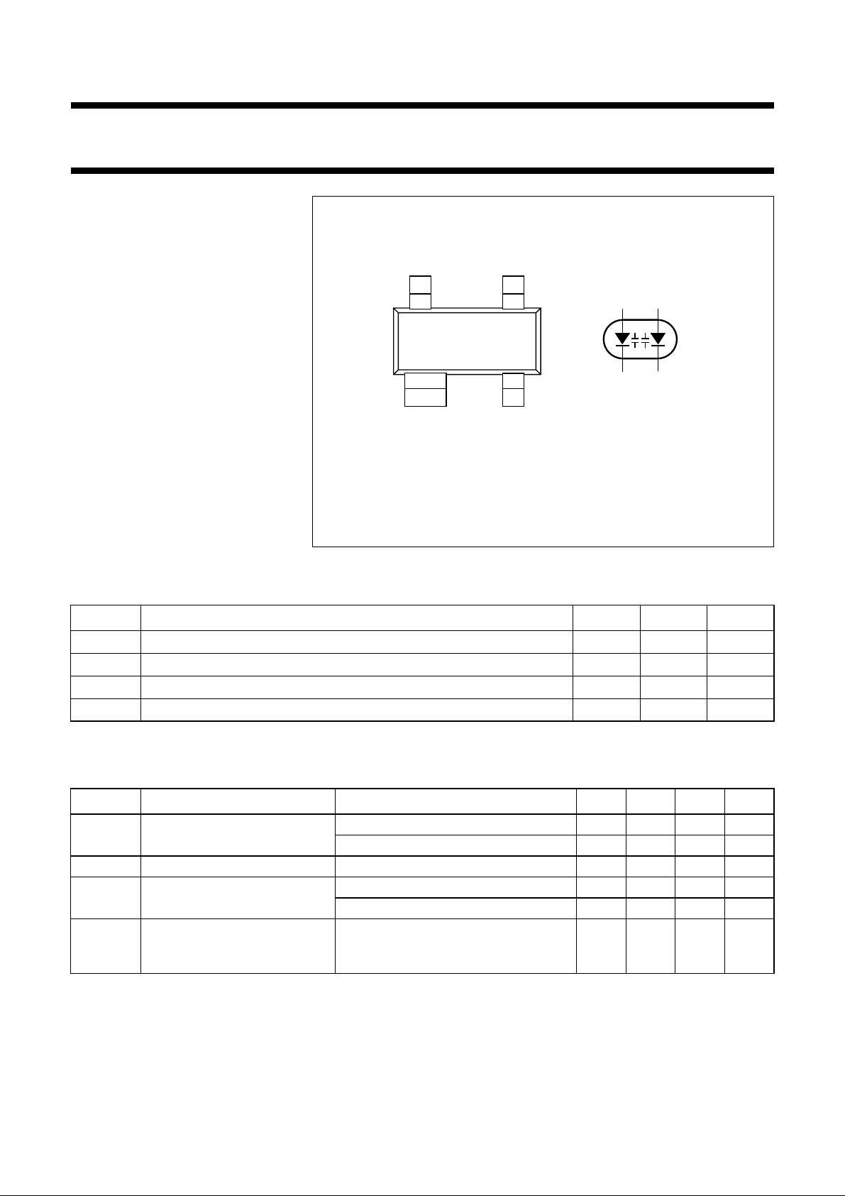
handbook, halfpage
43
21
4
3
1
2
DESCRIPTION
Top view
MAM172
The BBY62 is a variable capacitance
double diode, fabricated in planar
technology, and encapsulated in the
SOT143 small plastic SMD package.
The diodes are not electrically
Marking code: S4.
Fig.1 Simplified outline (SOT143), pin configuration and symbol.
connected to one another.
LIMITING VALUES
In accordance with the Absolute Maximum Rating System (IEC 134).
SYMBOL PARAMETER MIN. MAX. UNIT
V
R
I
F
T
stg
T
j
continuous reverse voltage
continuous forward current
storage temperature
operating junction temperature
−
30 V
− 20 mA
−55
−55
+150 °C
+125 °C
ELECTRICAL CHARACTERISTICS
=25°C; unless otherwise specified.
T
j
SYMBOL PARAMETER CONDITIONS MIN. TYP. MAX. UNIT
I
R
r
s
C
d
C
d1V()
-------------------C
d28V()
reverse current VR= 28 V; see Fig.3 −−10 nA
V
= 28 V; Tj=85°C; see Fig.3 −−200 nA
R
diode series resistance f = 470 MHz; note 1 −−1.2 Ω
diode capacitance VR= 1 V; f = 1 MHz; see Figs 2 and 4 − 16.5 − pF
V
= 28 V; f = 1 MHz; see Figs 2 and 4 1.6 − 2pF
R
capacitance ratio f = 1 MHz − 8.3 −
Note
is the value at which Cd= 9 pF.
1. V
R
1996 May 03 2
 Loading...