

Page 1

INSTRUCTIONS FOR USE
Avalon Fetal Monitor
FM20 / FM30 / FM40 / FM50
Release F.0 with Software Revision F.01.xx
FETAL MONITORING
Page 2

Printed in Germany 12/07
*M2703-9001D*
Part Number M2703-9001D
451261025621
S
Page 3

M2703-9001D
1Table Of Contents
1 Introduction 1
Who this Book is For 1
Confirm Fetal Life Before Using the Monitor 2
Introducing the Avalon Family of Fetal Monitors 3
Intended Use 3
Contraindications 3
Indications for Use 3
2 Installation 5
Installation Checklist 5
Unpacking and Checking the Shipment 6
Initial Inspection 6
Claims for Damage 6
Repacking 6
Mounting the Monitor 6
Connecting the Monitor to AC Mains 7
How and When to Carry Out the Test Blocks 7
Safety Tests 8
3 Basic Operation 9
Supported Measurements 10
Avalon FM20 and FM30 11
Avalon FM20 11
Avalon FM30 11
Avalon FM40 and FM50 12
Avalon FM40 12
Avalon FM50 12
Cordless Monitoring 13
Getting to Know Your Avalon FM20/FM30 14
Overview 14
Right Side 14
Rear 14
Left Side 15
Getting to Know Your Avalon FM40/FM50 16
Front 16
Rear 16
Tr a n s d u c e r s 17
Operating and Navigating 19
Keys 21
Permanent Keys 21
SmartKeys 21
Pop-Up Keys 22
i
Page 4

Using the Touchscreen 22
Disabling Touchscreen Operation 22
Selecting Screen Elements 22
Operating Modes 22
Automatic Screen Layouts 23
Settings 23
Active Settings 23
User Default 24
Factory Default 24
Global Settings 24
Changing Measurement Settings 24
Switching the Noninvasive Blood Pressure Measurement On and Off 25
Changing Monitor Settings 25
Adjusting the Screen Brightness 25
Ad ju st ing Tou ch To ne Volu me 25
Setting the Date and Time 25
Checking Your Monitor Revision 26
Preparing to Monitor a Patient 27
Switching On: FM20/FM30 27
Switching On: FM40/FM50 27
Adjusting the Display Angle (FM20/FM30) 27
Fastening Belts and Transducers 28
Using Belts with Button Fixings 29
Using Belt with Velcro Fixings 30
Connecting a Transducer to the Monitor 31
Checking/Setting Paper Scale 33
Paper Guide: FM40/FM50 33
Removing the Paper Guide: FM40/FM50 33
Loading Paper: FM20/FM30 35
Loading Paper: FM40/FM50 36
Paper-Out Indication 39
Choosing Paper Speed 39
Tearing Off the Paper: FM20/FM30 39
Tearing Off the Paper: FM40/FM50 39
Using the Paper Guide 40
Without the Paper Guide 40
Switching the Recorder On and Off 40
Advancing the Paper 42
Marking an Event 42
Entering Notes 43
Signal Quality 43
Starting Monitoring 43
Switching the Monitor to Stand-by 44
After Monitoring 44
Disconnecting from Power 44
Troubleshooting 45
ii
Page 5

4 Alarms 47
Alarm Mode 47
Visual Alarm Indicators 48
Audible Alarm Indicators 48
Alarm Tone Configuration 48
Standard Philips Alarms 48
ISO/IEC Standard 9703-2 Audible Alarms 48
Changing the Alarm Tone Volume 49
Acknowledging Alarms 49
Acknowledging Disconnect INOPs 49
Pausing or Switching Off Alarms 50
To Pause All Alarms 50
To Switch All Alarms Off 50
To Switch Individual Measurement Alarms On or Off 50
While Alarms are Paused or Off 51
Restarting Paused Alarms 51
Alarm Limits 51
Viewing Individual Alarm Limits (Alarm Mode “All” Only) 51
Changing Alarm Limits 52
Reviewing Alarms 52
Alarm Messages Window 52
Review Alarms Window 52
Latching Alarms 52
Viewing the Alarm Latching Settings 53
Alarm Latching Behavior 53
Testing Alarms 54
Alarm Behavior at On/Off 54
5 Patient Alarms and INOPs 55
Patient Alarm Messages 55
Technical Alarm Messages (INOPs) 57
6 Admitting and Discharging Patients 61
Admit/Discharge on the Monitor 61
Admitting a Patient 61
Editing Patient Information 62
Discharging a Patient 62
New Patient Check 62
OB TraceVue: via LAN 62
OB TraceVue: via RS232 63
7 Non-Stress Test Timer 65
Setting NST Autostart/Autostop 65
Viewing the NST Timer 65
Timer Expiry Notification 65
iii
Page 6

Accessing the NST Setup Pop-up Keys 65
Via the Timer SmartKey (Route 1) 66
Via the Main Setup SmartKey (Route 2) 66
Via the NST Field (Route 3) 66
Pop-up Keys for NST Timer Setup 66
Run Time 66
8 Monitoring FHR and FMP Using Ultrasound 69
Misidentification of MHR as FHR 69
Cross-Channel Verification 70
What You Need 70
Cordless Monitoring - Important Considerations 70
Preparing to Monitor 71
Selecting Fetal Heart Sound 72
Changing the Fetal Heart Sound Volume 72
Fetal Movement Profile 72
FMP Statistics 73
Switching FMP On and Off 74
Troubleshooting 74
Testing Ultrasound Transducers 75
9 Monitoring Twin FHRs 77
Important Considerations 77
Monitoring Twins Externally 78
Monitoring Internally 79
Cross-Channel Verification 80
Separating FHR Traces 80
Switching Trace Separation On and Off 80
Determining the Separation Order 81
When Trace Separation is On 81
‘Standard’ Separation Order 81
‘Classic’ Separation Order 82
When Trace Separation is Off 82
Troubleshooting 83
10 Fetal Heart Rate Alarms 85
Changing Alarm Settings 85
Turning Alarms On or Off 85
Changing Alarm Limits 85
Changing Alarm Delays 85
Changing Signal Loss Delay 86
11 Monitoring Triple FHRs 87
Important Considerations 87
Monitoring Triplets 88
Cross-Channel Verification 88
iv
Page 7

Separating FHR Traces 89
Switching Trace Separation On and Off 89
When Trace Separation is On 89
‘Standard’ Separation Order 89
‘Classic’ Separation Order 90
When Trace Separation is Off 90
Troubleshooting 91
12 Monitoring Uterine Activity Externally 93
What You Need 93
External Toco Monitoring 93
Resetting the Toco Baseline 94
Automatic Baseline Adjustment 94
Toco Sensitivity 94
Troubleshooting 95
Tes ti ng Toc o Tra ns du ce rs 96
13 Monitoring Uterine Activity Internally 97
What You Need 97
Internal (IUP) Monitoring 98
Zeroing the Monitor 98
Selecting the IUP Scale 98
Troubleshooting 99
14 Monitoring FHR Using DECG 101
Misidentification of MHR as FHR 101
What You Need 101
Making Connections 103
Monitoring DECG 103
Suppressing Artifacts 104
Printing the Waveform 105
Troubleshooting 105
Testing DECG Mode 106
15 Monitoring Noninvasive Blood Pressure 107
Introducing the Oscillometric Noninvasive Blood Pressure Measurement 107
Measurement Limitations 108
Measurement Methods 108
Reference Method 108
Preparing to Measure Noninvasive Blood Pressure 108
Correcting the Measurement if Limb is not at Heart Level 109
Understanding the Numerics 109
Starting and Stopping Measurements 109
Enabling Automatic Mode and Setting Repetition Time 110
Choosing the Alarm Source 110
Assisting Venous Puncture 111
v
Page 8

Calibration 111
Troubleshooting 111
16 Monitoring SpO
2
113
Selecting an SpO2 Sensor 113
Applying the Sensor 113
Connecting SpO2 Cables 114
Measuring SpO
2
114
Assessing a Suspicious SpO2 Reading 115
Understanding SpO2 Alarms 115
Alarm Delays 115
Adjusting the SpO2 Alarm Limits 115
Adjusting the Desat Limit Alarm 116
Adjusting the Pulse Alarm Limits 116
Setting Up Tone Modulation 116
Setting the QRS Volume 116
17 Monitoring Maternal Heart / Pulse Rate 117
Priority for Maternal Heart / Pulse Rate 117
Cross-Channel Verification 117
MHR from MECG Electrodes 117
Applying Electrodes 118
Making Connections 119
Monitoring MHR 119
Monitoring MECG 119
Applying Electrodes 120
Viewing the Waveform on the Screen 120
Printing the Waveform 120
Pulse Rate from SpO
2
Adjusting the Heart Rate / Pulse Alarm Limits 121
Average Pulse Rate from Noninvasive Blood Pressure 121
Troubleshooting 121
Testing MECG Mode 121
120
18 Printing the ECG Waveform 123
19 Paper Save Mode for Maternal Measurements 127
20 Recovering Data 129
Recovering Traces on Paper 129
Recovering Traces on an OB TraceVue System 130
Recording Stored Data 130
21 Care and Cleaning 133
General Points 133
Cleaning and Disinfecting 134
vi
Page 9

Cleaning Agents 134
Disinfecting Agents 135
Cleaning and Disinfecting Monitoring Accessories 135
Sterilizing 135
22 Maintenance 137
Inspecting the Equipment and Accessories 137
Inspecting the Cables and Cords 137
Maintenance Task and Test Schedule 138
Storing Recorder Paper 138
Cleaning the Printhead 139
Disposing of the Monitor 139
23 Accessories and Supplies
141
Information on Latex 141
Tr a n s d u c e r s 141
Fetal Accessories 142
DECG Accessories: Component Compatibility 143
MECG Accessories 143
Noninvasive Blood Pressure Accessories 144
Adult/Pediatric Multi-Patient Comfort Cuffs and Disposable Cuffs 144
Adult Antimicrobial Coated Reusable cuffs 144
Adult Soft Single Patient Single-Hose Disposable Cuffs 144
SpO2 Accessories 145
Recorder Paper 147
24 Specifications and Standards Compliance 149
Environmental Specifications 149
Physical Specifications 150
Performance Specifications 151
Fetal / Maternal 151
Noninvasive Blood Pressure 154
SpO
2
Recorder Specifications 158
Alarm Defaults 160
Compatible External Displays: FM40/FM50 Only 160
Manufacturer’s Information 161
Trademark Acknowledgement 161
Regulatory and Standards Compliance 161
Safety and Performance 161
Electromagnetic Compatibility (EMC) 161
EMC Testing 162
Reducing Electromagnetic Interference 162
System Characteristics 163
Electromagnetic Emissions and Immunity 163
Electromagnetic Immunity 164
156
vii
Page 10

Finding Recommended Separation Distances 165
Recommended Separation Distances from Other RF Equipment 167
Environment 167
Monitoring After a Loss of Power 168
ESU, MRI and Defibrillation 168
Cardiac Pacemakers and Electrical Stimulators 168
Fast Transients/Bursts 168
Symbols on the System 168
viii
Page 11

Who this Book is For
This book is for trained healthcare professionals using the Avalon FM20, FM30, FM40 and FM50
fetal/maternal monitors. It describes how to set up and use the monitor and transducers. Familiarize
yourself with all instructions including warnings and cautions before starting to monitor patients. Read
and keep the Instructions for Use that come with any accessories, as these contain important
information about application and care and cleaning that is not repeated in this book.
You should be:
• Trained in the use of fetal heart rate (FHR) monitors.
• Trained in the interpretation of FHR traces.
• Familiar with using medical devices and with standard fetal monitoring procedures.
1
1Introduction
For information on how to configure and service the monitor, refer to the Service Guide, or contact
your authorized service provider.
Your monitor may not have all of the features and options described in this guide. The exact
appearance of the monitor may differ slightly from that shown in the illustrations.
In this guide:
•A warning alerts you to a potential serious outcome, adverse event or safety hazard. Failure to
observe a warning may result in death or serious injury to the user or patient.
•A caution alerts you to where special care is necessary for the safe and effective use of the product.
Failure to observe a caution may result in minor or moderate personal injury or damage to the
product or other property, and possibly in a remote risk of more serious injury.
• Monitor refers to the entire fetal/maternal monitor. Display refers to the physical display unit.
Screen refers to everything you see on the monitor’s display, such as measurements, alarms, patient
data and so forth.
• Whenever a monitor’s identifier appears to the left of a heading or paragraph, it means that the
information applies to that monitor only. Where the information applies to all models, no
distinction is made.
1
Page 12

1 Introduction Confirm Fetal Life Before Using the Monitor
Confirm Fetal Life Before Using the Monitor
Fetal monitoring technology available today is not always able to differentiate a fetal heart rate (FHR)
signal source from a maternal heart rate (MHR) source in all situations. Therefore, you should confirm
fetal life by independent means before starting to use the fetal monitor, for example, by palpation of
fetal movement or auscultation of fetal heart sounds using a fetoscope, stethoscope, or Pinard
stethoscope. If you cannot hear the fetal heart sounds, and you cannot confirm fetal movement by
palpation, confirm fetal life using obstetric ultrasonography. Continue to confirm that the fetus is the
signal source for the FHR during monitoring.
Be aware that:
• a MHR trace can exhibit features that are very similar to those of a FHR trace, even including
accelerations and decelerations. Do not rely solely on trace pattern features to identify a fetal source.
• Fetal Movement Profile (FMP) annotations on a fetal trace alone may not always indicate that the
fetus is alive. The body of a deceased fetus can move and cause the monitor to annotate fetal body
movements.
Here are some examples where the MHR can be misidentified as the FHR.
• When using an ultrasound transducer:
– It is possible to pick up maternal signal sources, such as the maternal heart, aorta, or other large
vessels.
– Misidentification may occur when the MHR is higher than normal (especially when it is over 100
bpm).
• When using a fetal scalp electrode:
– Electrical impulses from the maternal heart can sometimes be transmitted to the fetal monitor
through a recently deceased fetus via the spiral scalp electrode cable, appearing to be a fetal signal
source.
– The recorded MHR (and any artifact) can be misinterpreted as a FHR (especially when it is over
100 bpm).
• When Fetal Movement Profile (FMP) is enabled:
FMP annotations in the absence of fetal life may be a result of:
– Movement of the deceased fetus during or following maternal movement.
– Movement of the deceased fetus during or following manual palpation of fetal movement
(especially if the pressure applied is too forceful).
– Movement of the ultrasound transducer.
– The ultrasound transducer detecting a maternal movement source, such as the mother’s aorta.
See also the chapters “Monitoring FHR and FMP Using Ultrasound” and “Monitoring FHR Using
DECG”.
To reduce the possibility of mistaking the MHR for FHR, it is recommended that you monitor both
maternal and fetal heart rates. The monitor’s cross-channel verification (CCV) facility can help by
automatically detecting when a MHR coincides with a FHR. For further details, see “Cross-Channel
Verification” on page 70.
2
Page 13

Introducing the Avalon Family of Fetal Monitors 1 Introduction
Introducing the Avalon Family of Fetal Monitors
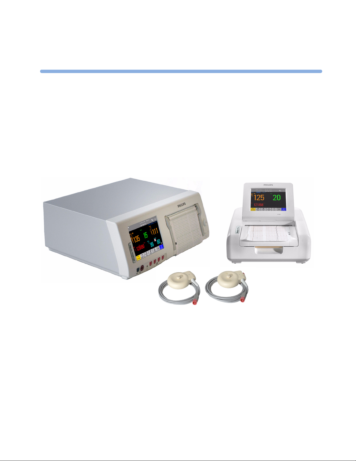
The Avalon family of fetal monitors consists of the Avalon FM20, FM30, FM40 and FM50. While the
FM20/FM30 and the FM40/FM50 have different form factors, the method of operation is very similar
for all monitors. The Avalon fetal monitors also share the same transducers and accessories, and are
compatible with the Avalon CTS Cordless Fetal Transducer System (M2720A).
Intended Use
The Philips Avalon FM20 (M2702A), FM30 (M2703A), FM40 (M2704A) and FM50 (M2705A)
Fetal/Maternal Monitors are intended for non-invasive monitoring of the physiological parameters of
pregnant women during antepartum testing and labor and delivery. The FM30 and FM50 are
additionally intended for invasive monitoring.
All monitors are intended for monitoring fetal and maternal heart rates, uterine activity, maternal noninvasive blood pressure, and additionally for the FM30, FM40 and FM50, oxygen saturation (SpO
All monitors are intended for generating alarms from fetal and maternal parameters, for displaying,
storing and recording patient data and related waves, transmitting patient data to a patient information
and surveillance system on a network, and for postpartum monitoring of the mother.
All monitors are intended for use by trained health care professionals.
).
2
They are intended for use in labor and delivery rooms, antepartum testing areas and during postpartum
recovery in the hospital environment. They are not intended for use in intensive care units or operating
rooms. The FM20 and FM30 are additionally intended for use in healthcare facilities outside hospitals,
for example in doctors’ offices, and for use in private households.
Contraindications
All monitors are NOT intended for:
– use during defibrillation, electro-surgery, or magnetic resonance imaging (MRI).
– ECG measurements on patients connected to external electrical stimulators or with cardiac
pacemakers.
– use with the IUP/ECG patient module (M2738A) in domestic establishments and those
connected directly to the public low-voltage supply network that supplies buildings used for
domestic purposes.
CAUTION US federal law restricts this device to sale by, or on the order of, a physician.
Indications for Use
The monitors are indicated for use by health care professionals for monitoring the physiological
parameters of pregnant women.
3
Page 14

1 Introduction Introducing the Avalon Family of Fetal Monitors
4
Page 15

Installation should be carried out by qualified service personnel, either by the hospital’s biomedical
department, or by Philips Support.
As the first step in preparing the monitor for use, follow the installation instructions given in this
chapter.
For a list of conventions used in this guide, see Chapter 2, “Basic Operation”.
Not all accessories and supplies may be available in all geographies. Please contact your local Philips
sales representative for details of availability.
Installation Checklist
Use this checklist to document your installation.
2
2Installation
Step Ta sk Check Box
when Task
Done
1 Perform initial inspection of delivery, unpack and check the shipment
(see “Unpacking and Checking the Shipment” on page 6)
2 Mount the monitor as appropriate for your installation
(see “Mounting the Monitor” on page 6)
3 Connect the fetal monitor to AC mains using the supplied power cord (see
“Connecting the Monitor to AC Mains” on page 7)
4 Perform Safety Tests (see “Safety Tests” on page 8) ❏
5 Check that default settings (including the line frequency) are appropriate for
your institution
6 Check/set the paper scale (see “Checking/Setting Paper Scale” on page 33) ❏
7 Load paper into the recorder (see “Loading Paper: FM20/FM30” on page 35
or “Loading Paper: FM40/FM50” on page 36, depending on your monitor)
8 Check/set the time and date (see “Setting the Date and Time” on page 25) ❏
9 Check/set paper speed (see “Choosing Paper Speed” on page 39) ❏
10 Perform System Test as necessary (see the Service Guide) ❏
11 Test Transducers (see “Testing Ultrasound Transducers” on page 75 and
“Testing Toco Transducers” on page 96)
❏
❏
❏
❏
❏
❏
5
Page 16

2 Installation Unpacking and Checking the Shipment
Unpacking and Checking the Shipment
The monitor and any supporting options ordered are supplied packed in protective shipping cartons.
Initial Inspection
Before unpacking, visually check the packaging and ensure that there are no signs of mishandling or
damage.
Open the package carefully and remove the instrument and accessories.
Check that the contents are complete and that the correct options and accessories have been delivered.
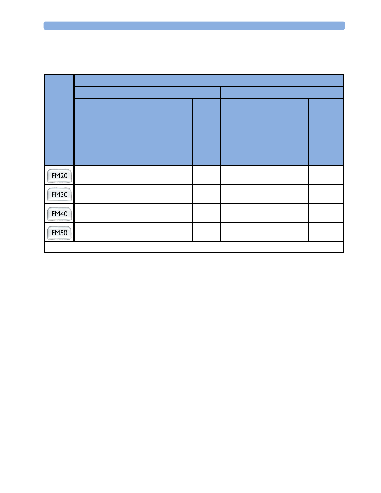
System Components, Accessories and Supplies FM20 FM30 FM40 FM50
To c o+ transducer (with belt clip) - 1 - 1
Toco transducer (with belt clip) 1 - 1 -
US transducer (with belt clip) 1111
Patient Module for DECG/MECG/IUP optional
IUP Adapter Cable
DECG reusable legplate adapter cable - 1 - 1
MECG adapter cable - 1 - 1
Event Marker optional optional optional optional
Fetal paper pack (country-specific, installed) 1111
Powercord 1111
Printed Instructions for Use 1111
Documentation DVD-ROM: includes FM20/30 Service
Guide, FM40/50 Service Guide, Instructions for Use
(including localized versions), and Training Guide
1.
For assessment of maternal heart rate only.
2. Ships with Patient Module.
2
1
1111
optional optional
11
1
optional
Claims for Damage
If the shipping cartons are damaged, contact the carrier.
If any of the equipment is damaged, contact both the carrier and your local Philips service organization
for repair or replacement arrangements.
Repacking
Retain the original packing carton and material, in case you need to return equipment to Philips for
service. If you no longer have the original packing materials, Philips can advise you on alternatives.
Mounting the Monitor
The monitor can be rested on a flat surface, set at an angle using the built-in stand, or mounted on a
wall, on a cart or on a rollstand. See the Service Guide for details.
The monitor can be rested on a flat surface, or on a cart. See
6
your monitor’s Service Guide for details.
Page 17

Connecting the Monitor to AC Mains 2 Installation
Connecting the Monitor to AC Mains
The monitor is an electrical Class II device in which the protection against electric shock does not rely
on basic insulation and a protective earth conductor but on double and/or reinforced insulation.
The monitor is an electrical Class I device. Protection against electric shock is provided by a protective
earth conductor.
The monitor has a wide-range power supply that allows you to operate the monitor from an AC
(alternating current) power source of 100 V to 240 V (± 10%) and 50 or 60 Hz (± 5%).
WARNING • Always use the supplied power cord with the earthed mains plug to connect the monitor to an
earthed AC mains socket. Never adapt the mains plug from the power supply to fit an unearthed AC
mains socket.
• Check that the line frequency is correctly set for your institution (50 Hz or 60 Hz) before putting
the monitor into service.
• FM20/FM30 only: The protective earth conductor is required for EMC purposes. It has no
protective function against electric shock! The protection against electric shock in this device is
provided by double and/or reinforced insulation.
• Do not use AC mains extension cords or multiple portable socket-outlets.
How and When to Carry Out the Test Blocks
The following table defines which test and inspection blocks need to be performed, and when they are
required.
Tes t Bl oc k Test or Inspection to be Performed Te s t B l o c k R eq u i r ed f o r
Which Events?
Visual Inspect the monitor, transducers and cables for
any damage.
Are they free of damage?
Power On Power on the monitor. Does it boot up
successfully without errors? After boot up the
monitor sounds a tone, and can you see the
monitoring main screen.
If recorder power-on auto-start is configured to
On, does the recorder print “Selftest OK” across
the trace paper? (See page 26 for details.)
Safety Tests (1) to (4) Perform safety tests (1) to (4), as described in your
monitor’s Service Guide, for standalone devices if
required by local regulations, and each time you
combine equipment to form a system, or exchange
system components.
Installation
Preventive Maintenance
Installation
Preventive Maintenance
Installation
Preventive Maintenance
7
Page 18

2 Installation Safety Tests
Tes t Bl o c k Test or Inspection to be Performed Te s t B l oc k Re q u i re d f o r
Which Events?
Performance Test the transducers (see “Testing Ultrasound
Transducers” on page 75 and “Testing Toco
Tr a ns du c er s” o n p a g e 9 6 ) .
System Perform the system test according to IEC/EN
60601-1-1/IEC/EN 62353, if applicable, after
combining equipment to form a system (see your
monitor’s Service Guide).
For test and inspection information regarding repairs, upgrades and all other service events, refer to
your monitor’s Service Guide.
Installation
Preventive Maintenance
Combining system
components
Safety Tests
Details of the safety tests and procedures required after an installation or an exchange of system
components are described in your monitor’s Service Guide. These safety tests are derived from
international standards but may not be sufficient to meet local requirements.
WARNING • Do not use additional AC mains extension cords or multiple portable socket-outlets. If a multiple
portable socket-outlet is used, the resulting system must be compliant with IEC/EN 60601-1-1.
• Do not connect any devices that are not supported as part of a system.
• Do not use a device in the patient vicinity if it does not comply with IEC/EN 60601-1. The whole
installation, including devices outside of the patient vicinity, must comply with IEC/EN 60601-1-1.
Any non-medical device, including a PC running an OB TraceVue system, placed and operated in
the patient’s vicinity must be powered via a separating transformer (compliant with IEC/EN 606011-1) that ensures mechanical fixing of the power cords and covering of any unused power outlets.
8
Page 19
3
3Basic Operation
This chapter gives you an overview of the monitor and its functions. It tells you how to perform tasks
that are common to all measurements (such as entering data, switching a measurement on, changing
some monitor settings, and setting up the recorder). The alarms section gives an overview of alarms.
The remaining sections tell you how to perform individual measurements, and how to care for and
maintain the equipment.
9
Page 20
3 Basic Operation Supported Measurements
Supported Measurements
The following measurements are supported:
Supported Measurements
Fetal Maternal
Fetal
Monitor
Model
)
2
Fetal Heart Rate
(FHR) via US
Including Twins
●❍●
● ❍●●●●●❍ ❍
●❍●
● ❍●●●●●● ●
Key: ● = Standard
Triple F H R vi a U S
To co
FHR
via Direct ECG
(DECG)
Intrauterine Pressure
(IUP)
--
--
= Optional
❍
Maternal Heart Rate
(MHR) via maternal
ECG electrodes
Maternal ECG
(MECG)
●
●
-
-
Noninvasive Blood Pressure
with Pulse Rate
Pulse Oximetry
❍
●●
- = Not Available
with Pulse Rate
(Maternal SpO
-
10
Page 21
Avalon FM20 and FM30 3 Basic Operation
Avalon FM20 and FM30
This section outlines the capabilities of your monitor.
Avalon FM20
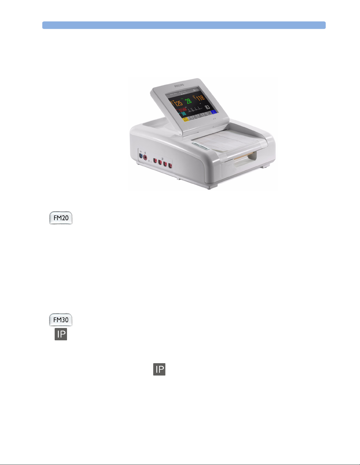
The Avalon FM20 fetal/maternal monitor provides a solution for external fetal monitoring
applications, and optional non-invasive maternal vital signs.
You can monitor fetal heart rates (FHRs) externally using ultrasound, uterine activity using an external
Toco transducer, and the maternal heart rate (MHR) via maternal ECG electrodes, and optionally,
non-invasive blood pressure.
Measurements are displayed on a 6.5-inch color display as numerics. The display is a touchscreen, and
you operate the monitor using this touchscreen interface. The integrated recorder documents fetal and
maternal measurements as well as user defined annotations.
You can connect the monitor to an OB TraceVue obstetrical documentation and surveillance system
via the RS232 connection, or over a LAN connection (with OB TraceVue Revision E.00.00 and later).
Avalon FM30
The Avalon FM30 fetal/maternal monitor offers a solution for both external and internal fetal
monitoring applications, and optional non-invasive maternal vital signs.
The Avalon FM30 shares all the features and capabilities of the Avalon FM20. In addition, you can
monitor one FHR internally via direct fetal electrocardiogram (DECG), uterine activity internally
using an intra-uterine pressure (IUP) catheter together with a Toco
optionally, maternal oxygen saturation (SpO
The Avalon FM30 carries the label, indicating that it is capable of intrapartum monitoring.
+
transducer or patient module, and
).
2
11
Page 22
3 Basic Operation Avalon FM40 and FM50
Avalon FM40 and FM50
This section outlines the capabilities of your monitor.
Avalon FM40
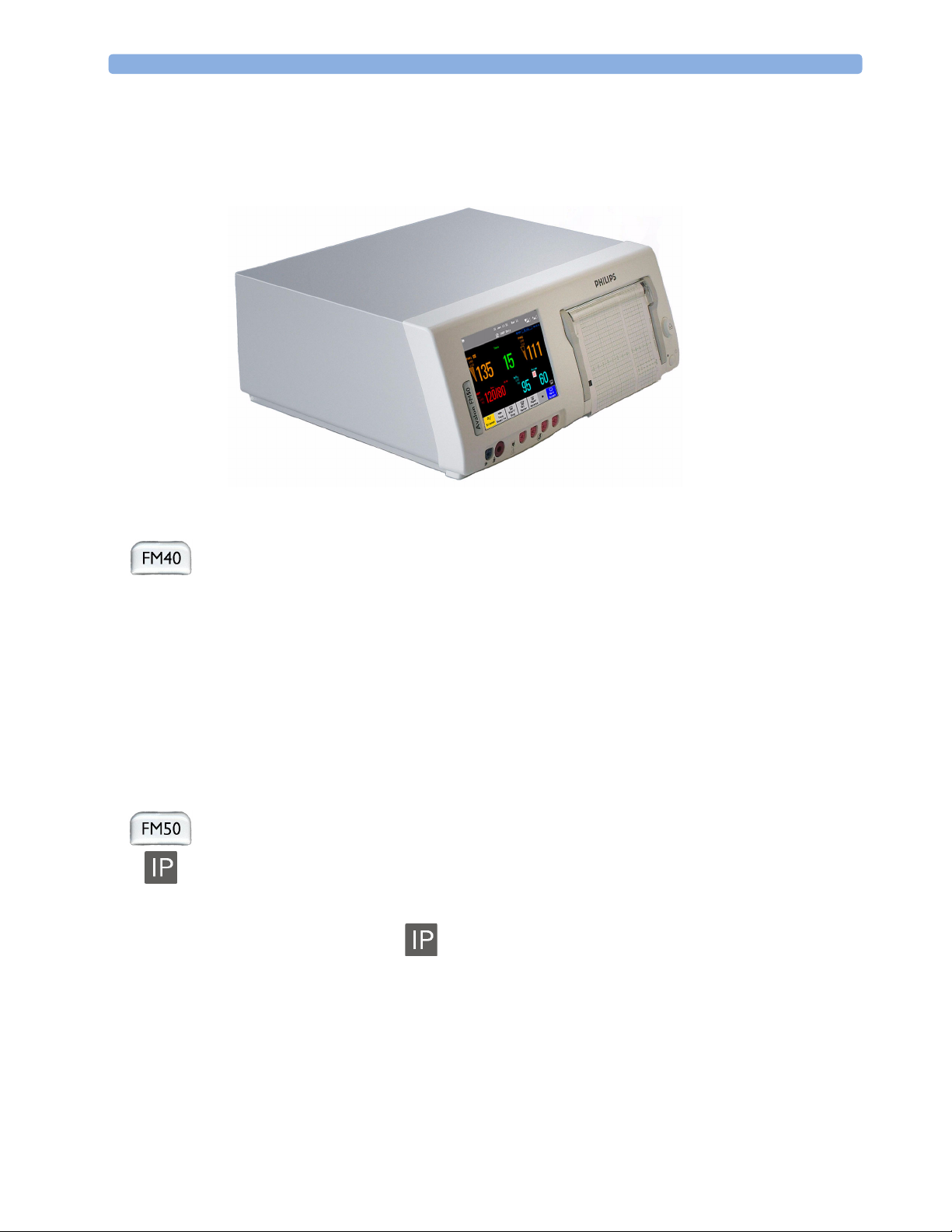
The Avalon FM40 fetal/maternal monitor provides a solution for external fetal monitoring
applications, and optional non-invasive maternal vital signs.
You can monitor fetal heart rates (FHRs) externally using ultrasound, uterine activity using an external
Toco transducer, and the maternal heart rate (MHR) via maternal ECG electrodes, and optionally,
non-invasive blood pressure and maternal oxygen saturation (SpO
Measurements are displayed on a 6.5-inch color display as numerics. The display is a touchscreen, and
you operate the monitor using this touchscreen interface. The integrated recorder documents fetal and
maternal measurements as well as user defined annotations.
You can connect the monitor to an OB TraceVue obstetrical documentation and surveillance system
via the RS232 connection, or over a LAN connection (with OB TraceVue Revision E.00.00 and later).
Avalon FM50
The Avalon FM50 fetal/maternal monitor offers a solution for both external and internal fetal
monitoring applications, and optional non-invasive maternal vital signs.
The Avalon FM50 shares all the features and capabilities of the Avalon FM40. In addition, you can
monitor one FHR internally via direct fetal electrocardiogram (DECG), and uterine activity internally
using an intra-uterine pressure (IUP) catheter together with a Toco
The Avalon FM50 carries the label, indicating that it is capable of intrapartum monitoring.
).
2
+
transducer or patient module.
12
Page 23
Cordless Monitoring 3 Basic Operation
Cordless Monitoring
All monitors are compatible with the Avalon CTS Cordless Fetal Transducer System (M2720A). Note
the following points regarding cordless monitoring:
• One Avalon CTS Cordless Fetal Transducer System can be connected at a time.
• Monitoring multiple pregnancies using cordless transducers is not supported.
• Using a mixture of wired and cordless fetal transducers is not supported. You can use either wired or
cordless fetal transducers.
• When the monitor recognizes an Avalon CTS interface cable M2731-60001 (red connector) or
M2732-60001 (black connector, for rear connection on FM40/FM50 only), it gives confirmation
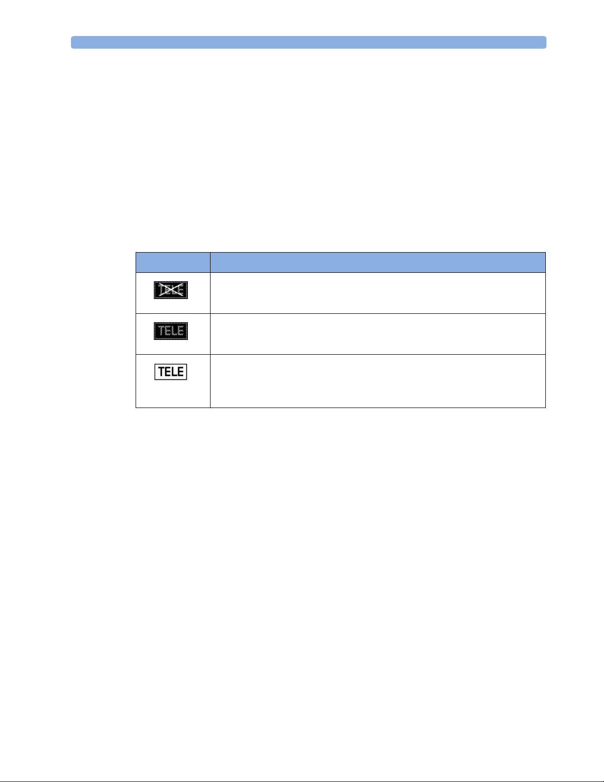
by showing the following status indicator in the lower right-hand corner of the screen:
Indicator Meaning
Avalon CTS interface cable is connected to the monitor, but the Avalon CTS base
station is not connected to the interface cable, disconnected from AC mains, or is
in Stand-by.
Avalon CTS interface cable is connected to the monitor, Avalon CTS base station
is connected, powered on, and cordless transducers are ready to use, but no cordless
transducers are currently active (all are still docked in the base station).
Avalon CTS interface cable is connected to the monitor, Avalon CTS base station
is connected, powered on, and at least one cordless transducer has been taken out
of the base station and is active. As cordless transducers have priority over wired
transducers, any connected wired transducers are disabled.
• Cordless transducers have priority over wired transducers. When an Avalon CTS base station is
connected via the appropriate interface cable to the fetal monitor, and there are also wired
transducers connected to the monitor, the wired transducers are disabled whenever a cordless
transducer is active. To change back to using wired transducers, dock the cordless transducers in the
Avalon CTS base station or switch the base station to Stand-by, and continue monitoring with the
wired transducers.
• When using a cordless ultrasound transducer from an Avalon CTS system, the monitor
automatically sets the Fetal Movement Profile (FMP) to Off. You can enable the FMP again should
you wish, (see “Switching FMP On and Off” on page 74), but you should refer to the sections
“Cordless Monitoring - Important Considerations” on page 70 and “Fetal Movement Profile” on
page 72.
13
Page 24
3 Basic Operation Getting to Know Your Avalon FM20/FM30
Getting to Know Your Avalon FM20/FM30
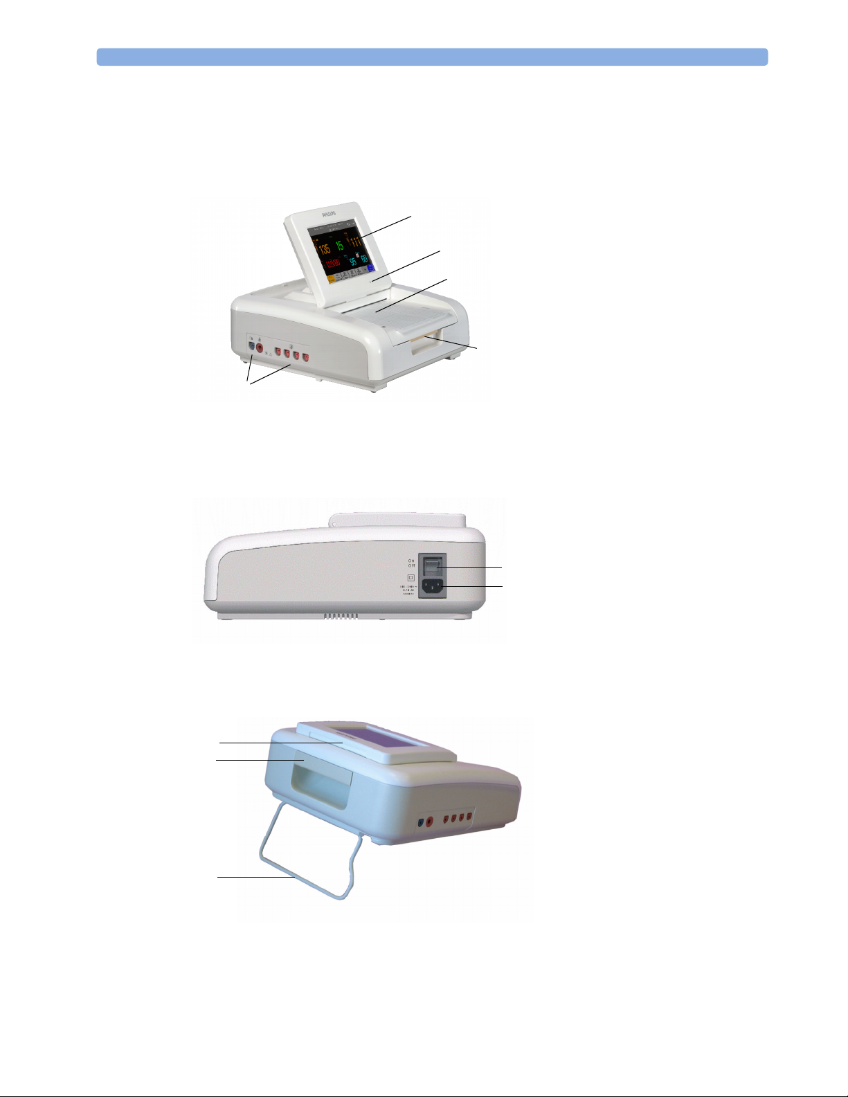
Overview
1 Touchscreen display (tilt and fold)
1
2
3
5
2 Power LED
3 Paper drawer
4 Paper drawer release
5 Connectors (see Left Side view)
4
Right Side
Rear
10
8
6
ON/OFF switch
7
Power connector
6
7
8
Carrying handle
9
Built-in stand
10
Display release
14
9
Page 25

Getting to Know Your Avalon FM20/FM30 3 Basic Operation
Left Side
11
Fetal sensor sockets - each
socket accepts any fetal
transducer, an Avalon CTS
Cordless Fetal Transducer
System base station (connected
via the interface cable M2731-
60001), or event marker
12
Noninvasive blood pressure
1213
11
socket (optional)
13
SpO2 socket (optional, FM30
only)
15
Page 26
3 Basic Operation Getting to Know Your Avalon FM40/FM50
Getting to Know Your Avalon FM40/FM50
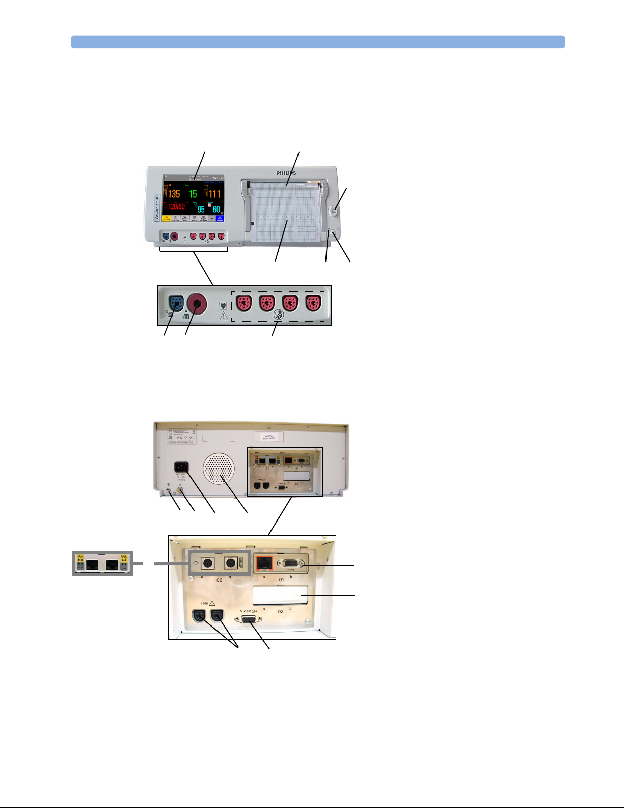
Front
On/Off/Standby switch1
4
8
9
7
5
6
3
2
2 Power LED
3 Recorder paper table
4 Touchscreen color display
5 Transparent paper guide with tear-off
edge
6 Paper eject button. Press to open paper
drawer. Press again and hold when
removing paper.
7 Fetal sensor sockets. Connect any fetal
1
sensor or patient module here,
including Avalon CTS via M273160001 interface cable (with red
connector).
8 Noninvasive blood pressure socket
9 SpO
socket
2
Rear
Reserved for future use: protective
earth intended for use in system
1
2 Equipotential grounding point
3 Power cord connector
4 Loudspeaker
5 Slot 01 for optional LAN / RS232
12
3
4
(A)(B)
6
9
8
6 Slot 02 for optional interfaces:
5
7
7 Slot 03 reserved for future use
8 Video output (VGA)
9 Telemetry interface. If not using one of
installations.
system interface (for connection to an
obstetrical information and
surveillance system)
• Either dual PS/2 system interface
(A) for mouse and keyboard
connection)
• Or MIB interface (B) for external
touch screen connection
the fetal sensor sockets, one Avalon
CTS can be connected at a time to
either socket using the M2732-60001
interface cable (with black connector).
16
Page 27
Transducers 3 Basic Operation
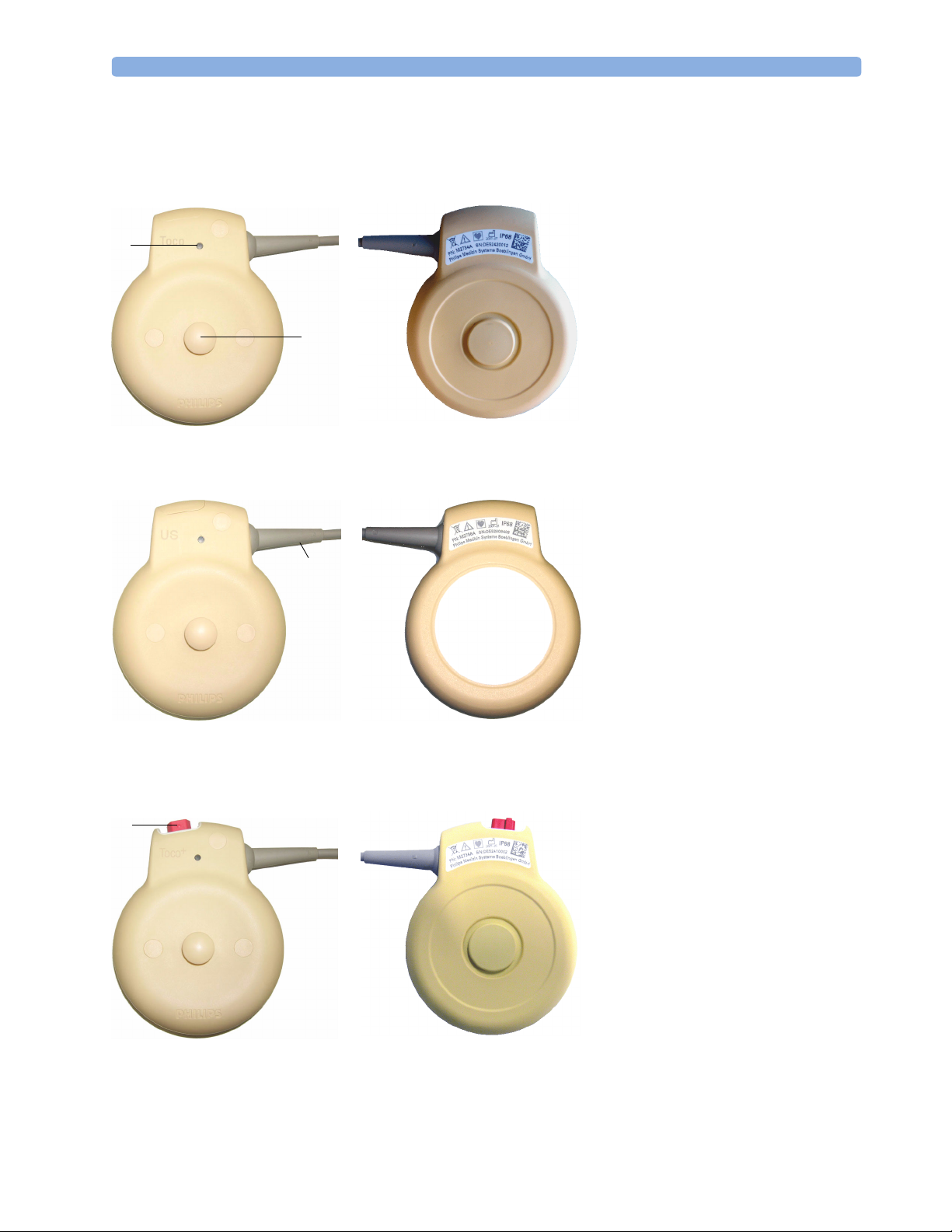
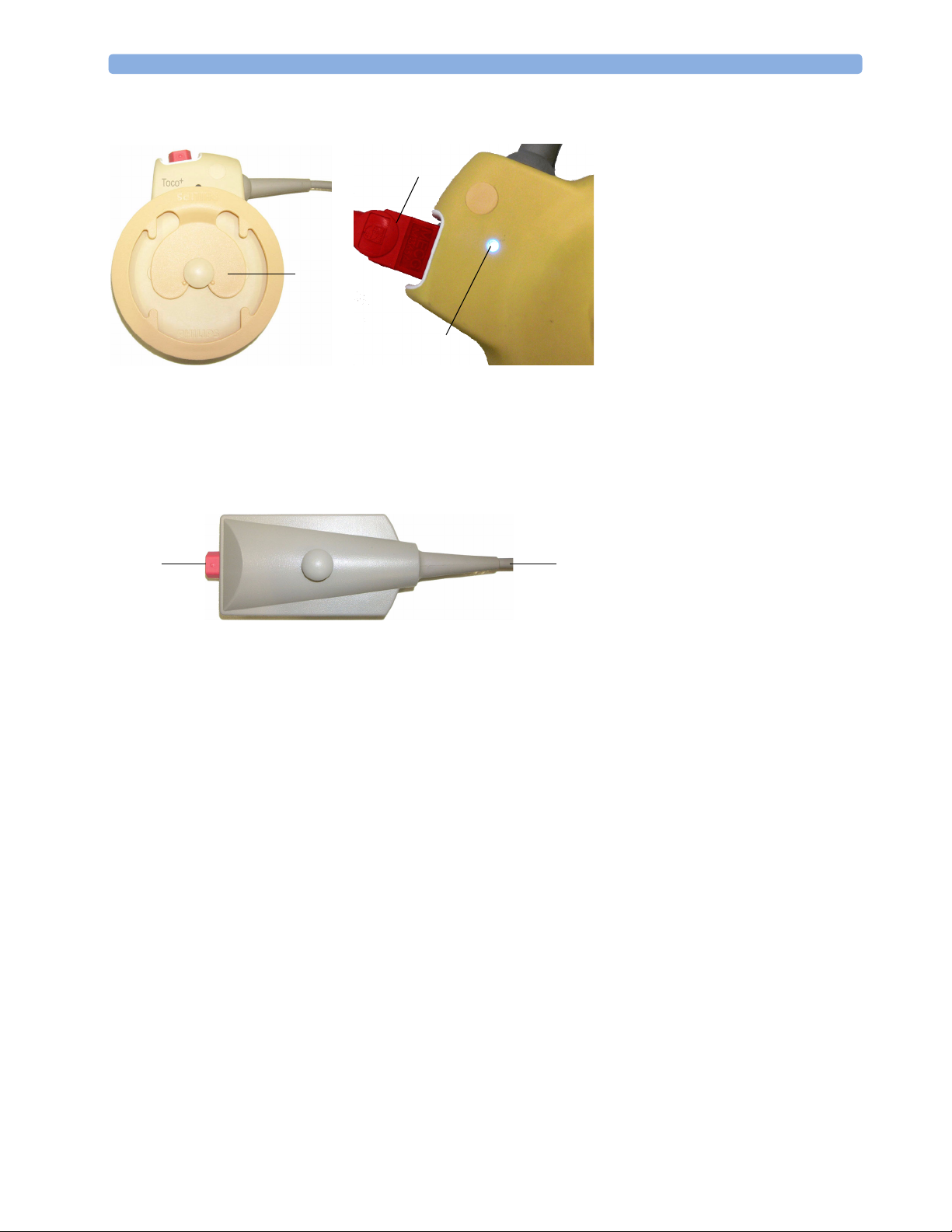
Transducers
1
Transducer Finder LED - lights
up on the transducer providing
1
2
Toc o Tr a n s d u c er
(M2734A)
the measurement source.
2
Belt Button
3
Cable - connects to any of the
four Fetal Sensor Sockets on the
monitor
3
Ultrasound Transducer
(M2736A)
4
Connector - for connecting
4
ECG/IUP adapter cables
+
(M2735A Toco
only)
transducer
Toco+ Transducer with ECG/IUP capability
(M2735A)
17
Page 28
3 Basic Operation Transducers
5
Butterfly belt clip (shown
fitted; for use with belts
6
without button holes)
6
Close-up of MECG adapter
cable connected to Toco
+
transducer
7
5
Close-up of active Finder LED
7
8
Connector - for connecting
ECG/IUP adapter cables (same
+
as for Toco
9
8
9
Cable - connects to any of the
four Fetal Sensor Sockets on the
monitor
transducer)
Patient module for ECG/IUP
(M2738A)
18
Page 29
Operating and Navigating 3 Basic Operation
Operating and Navigating
Your monitor has a touchscreen. Everything you need to operate the monitor, other than to turn it on
and off, is contained on its screen. Most screen elements are interactive. Screen elements include
measurement numerics, screen keys, information fields, status indicators, alarms fields and menus.
If an optional external touch display is connected to the monitor, you can operate the monitor using
the external touch display.
1
15
18
17
16
324
Toco
Stop
31 Jan
INOP Only
SpO
Paper
Advance
13
Doe, Jane
20 minNST
FHR1
NBP Auto
Sys.
All Settings restored successfully
Silence
Toco
Baseline
Start/
14
13:31
2
Dischrge
FHR2
Admit
5
Bed 11
Pulse
12
67
8
9, 10
Main
Screen
11
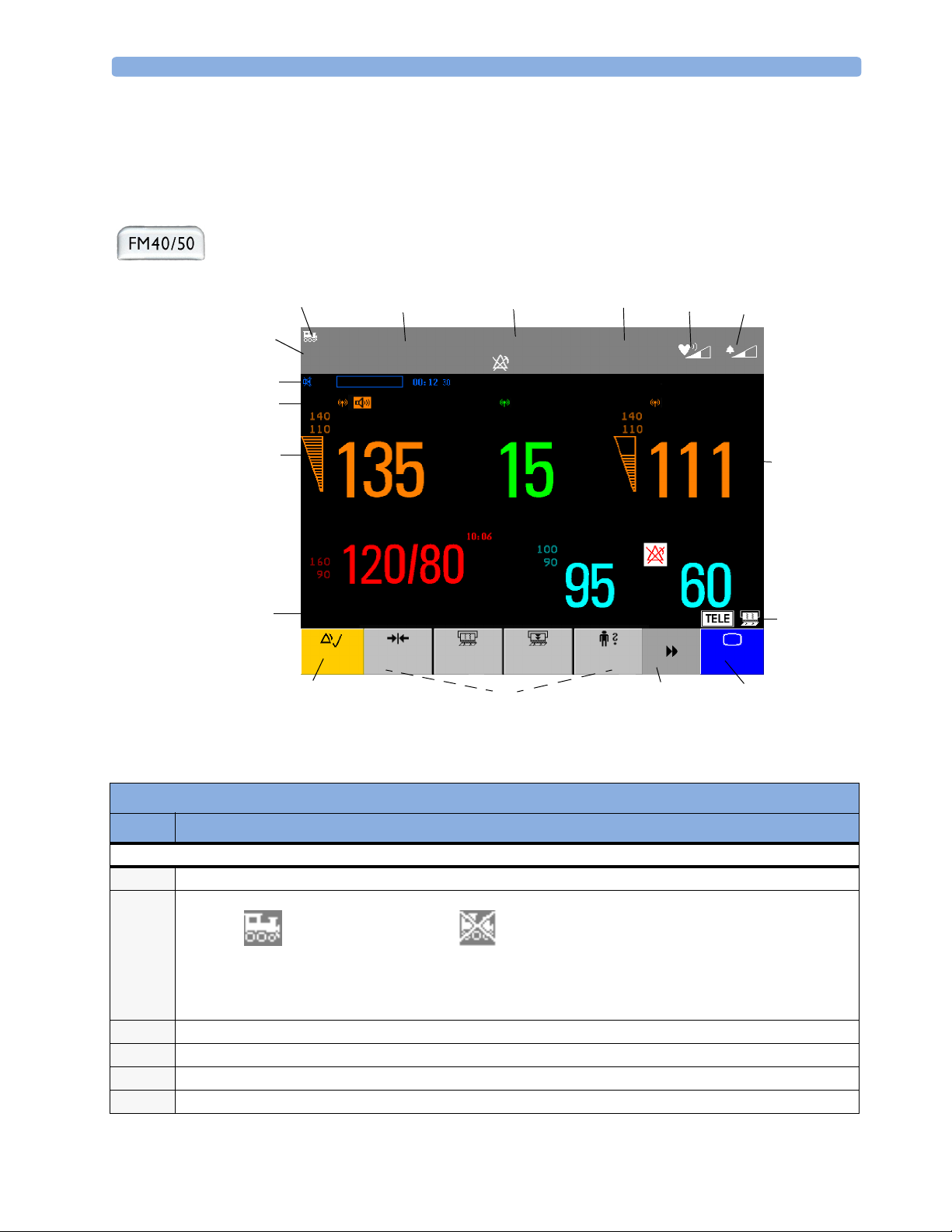
Screen Elements
Item Description
Monitor Information Line
INOP and alarm status area - shows active alert messages
1
LAN connection status indicator only. RS232 system connection is not indicated.
2
Monitor connected to OB
Tr a c e V u e
Patient identification
3
Date and time
4
Bed label (when connected to a Philips OB TraceVue system)
5
Fetal heart sound volume adjust/indicator
6
LAN cable connected, but no
connection to OB TraceVue
If no indicator is shown, there
is no network connection.
19
Page 30
3 Basic Operation Operating and Navigating
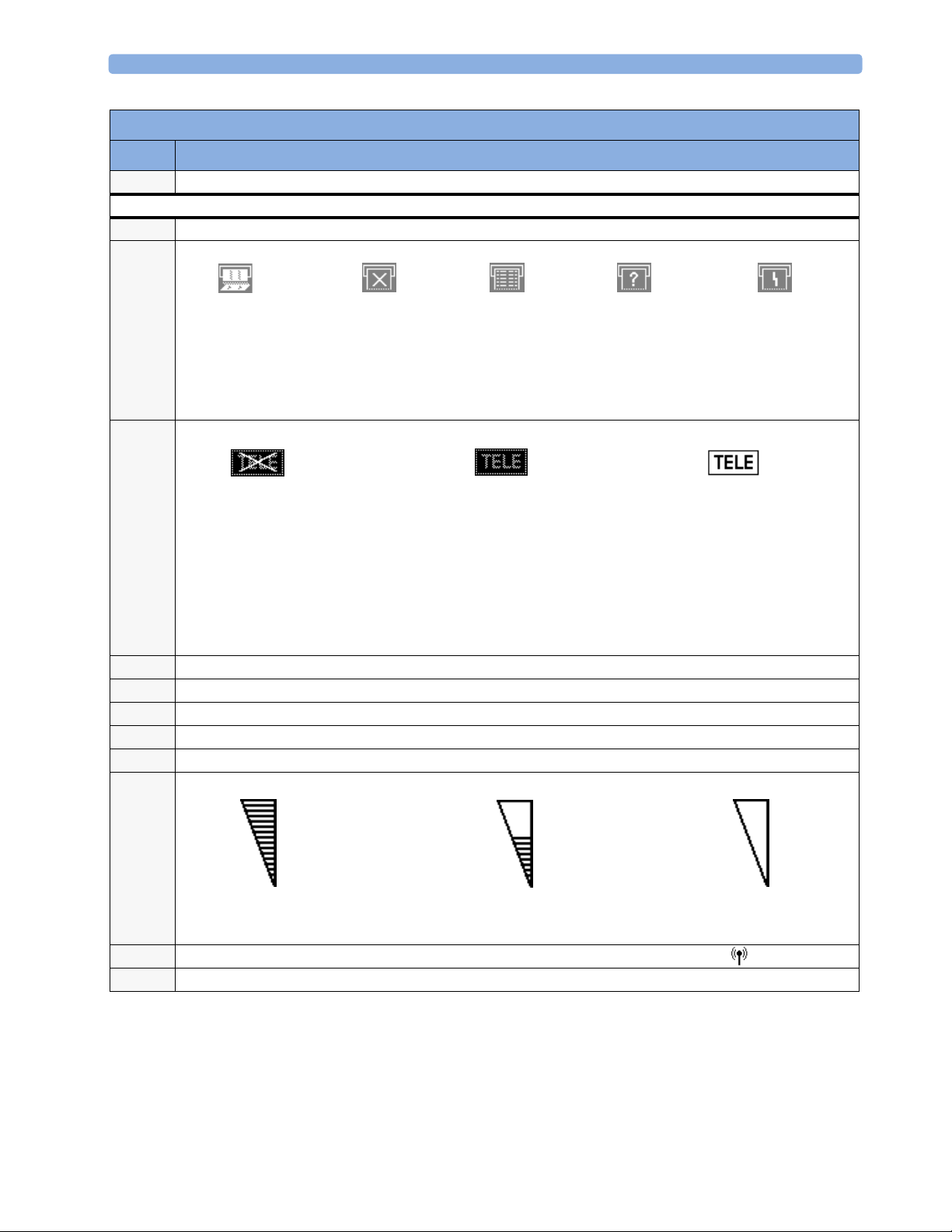
Screen Elements
Item Description
Alarm volume adjust/indicator
7
Other Screen Elements
Numeric/measurement values
8
Status indicator - for fetal trace recorder
9
Fetal recorder On
Status indicator - for Avalon CTS system:
10
Avalon CTS interface cable is
connected to the monitor, but
Avalon CTS base station is not
connected to the interface cable,
disconnected from AC mains, or is
in Stand-by.
Close all open menus and windows and return to main screen
11
Scroll to display more SmartKeys
12
SmartKeys - these can vary according to your monitor’s configuration
13
Silence - key which acknowledges all active alarms by switching off audible alarm indicators
14
Status line - shows status and prompt messages
15
Signal quality indicator:
16
Fetal recorder Off
(when Paper Save
Mode is off )
Avalon CTS interface cable is
connected to the monitor, Avalon CTS
base station is connected, powered on,
and cordless transducers are ready to
use, but no cordless transducers are
currently active (all are still docked in
the base station).
Fetal recorder Off
(when Paper Save
Mode is on)
Recorder problem that can
be solved by the user (for
example, paper out, paper
jam, wrong paper scale set)
Avalon CTS interface cable is
connected to the monitor, Avalon CTS
base station is connected, powered on,
and at least one cordless transducer has
been taken out of the base station and
is active. Any connected wired
transducers are disabled.
Fetal recorder is
defective. Call service.
20
Good/full
Measurement label (a cordless measurement from a connected Avalon CTS system is indicated by the symbol)
17
NST timer, if configured (default is off)
18
Acceptable/medium
Poor/no signal
Page 31

Operating and Navigating 3 Basic Operation
Keys
The monitor has three different types of keys.
Permanent Keys
A permanent key is a graphical key that remains permanently on the screen, giving you fast access to
functions.
SmartKeys
Silence
- acknowledges all active alarms by switching off audible alarm indicators.
Main Screen - closes all open menus and windows and returns to the main screen.
SmartKeys are configurable graphical keys, located at the bottom of the main screen. They give you fast
access to functions. The selection of SmartKeys available on your monitor depends on your monitor
configuration and on the options purchased.
Main Setup - enter main setup
menu.
Pause Alarms - pauses alarm
indicators. Pause duration depends on
monitor configuration. If pause
duration is infinite, this key is labeled
Recorder Start/Stop - turn the
trace recorder on or off.
Paper Advance - advance the
paper automatically to the next fold.
Alarms Off.
Select again to immediately re-enable
alarm indicators.
Start Recordng - turn the
trace recorder on.
Stop Recordng - turn the trace
recorder off.
Start ECG - start printing the
ECG wave.
Stored Data Rec - print trace
recovery data from the monitor’s
memory.
Admit/Dischrge
identification menu to admit/
discharge
Toco Baseline - reset Toco
baseline
- enter patient
Enter Notes - enter notes
Timer - enters NST timer window
Zero IUP - zero IUP measurement Set Marker - mark an event
Start/Stop:
- start/stop manual noninvasive blood
pressure measurement
- start auto series
- stop current automatic measurement
within series
Stop All - stop all noninvasive blood
pressure measurements
21
Page 32

3 Basic Operation Operating Modes
Start NBP
- start manual noninvasive blood
pressure measurement
- start auto series
Repeat Time - set the time
interval between two noninvasive
blood pressure measurements
Monitor Standby - enter
Stand-by mode, suspends monitoring.
All numerics and waves disappear
from the display. All settings and
patient data information are retained.
Pop-Up Keys
Pop-up keys are context-sensitive graphical keys that appear automatically on the monitor screen when
required. For example, the confirm pop-up key appears when you need to confirm a change.
Using the Touchscreen
Select screen elements by pressing them directly on the monitor’s screen.
:
Stop NBP:
- stop manual noninvasive blood pressure
measurement
- stop current automatic measurement
within series
Defaults - load User Default
Disabling Touchscreen Operation
To temporarily disable touchscreen operation of the monitor, press and hold the Main
Screen permanent key for about three seconds. A red padlock will blink on the Main
Screen permanent key.
Press and hold the Main Screen permanent key again for about three seconds to re-enable the
touchscreen operation.
Selecting Screen Elements
Select a screen element to tell the monitor to carry out the actions linked to the element.
You access most screen elements by touching that element directly. For example, select the FHR1
numeric to call up the Setup FHR1 menu, or select the Start/Stop SmartKey to start or stop
the fetal trace recorder.
However, some smaller screen elements are grouped together at the top of the screen in the
information area. To access one of these elements, touch anywhere in the information area, and select
the element from the selection list that appears. For example, to view alarm messages:
1 Touch the alarm status field, or anywhere else in the information area at the top of the screen. The
window with the selection list opens.
2 Select Alarm Messages from the list. This opens the Alarm Messages window, from where
you can proceed to view the alarm messages.
Operating Modes
When you switch the monitor on, it starts up in monitoring mode. To change to a different mode:
1 Select the Main Setup menu.
22
Page 33

Automatic Screen Layouts 3 Basic Operation
Select Operating Modes and choose the mode you require.
2
Your monitor has four operating modes. Some are passcode protected.
• Monitoring Mode: This is the normal mode for monitoring patients. You can change elements such
as alarm limits, and so forth. When you discharge the patient, these elements return to their default
values. Changes can be stored permanently in Configuration Mode. You may see items, such as
some menu options, that are visible but ‘grayed out’ so that you can neither select nor change them.
These are for your information and can be changed in Configuration Mode.
• Demo Mode: Passcode protected, this is for demonstration and training purposes. You must not
change into Demonstration Mode during monitoring. When transducers are connected to the
monitor and the recorder is on, a demo trace is recorded, but this is not transmitted to an
information and surveillance system such as OB TraceVue.
• Configuration Mode: Passcode protected, this is for personnel trained in configuration tasks. These
tasks are described in the Service Guide. During installation the monitor is configured for use in
your environment. This configuration defines the default settings you work with when you switch
on.
• Service Mode: Passcode protected, this is for trained service personnel.
Config
When the monitor is in Demonstration Mode, Configuration Mode, or
Service Mode, this is indicated by a box containing the mode name. Select
this field to change to a different mode.
Automatic Screen Layouts
Your monitor’s preconfigured screen layouts define how measurement information is arranged on
screen. The monitor automatically applies the correct screen layout for the measurements you are
monitoring. No user action is required.
Connecting or disconnecting transducers, or switching the noninvasive blood pressure measurement
on or off, results in an automatic adjustment of the screen layout. When a measurement is off, its
numerics are removed from the monitor’s screen. The monitor stops acquiring data and generating
alarms for this measurement. If you disconnect a transducer while it is performing a measurement, the
monitor issues a disconnect INOP (and in the case of SpO
question marks).
Settings
This section describes the various settings available on the monitor.
Active Settings
What the monitor displays, and the way it operates, is controlled by its settings. They determine screen
content, layout, high and low alarm limits and so forth.
The “active settings” are the current settings the monitor uses, including any adjustments made by the
last user. Active settings are not permanent, but are retained after a loss of mains power.
, replaces the measurement numeric with
2
There are also two preconfigured default settings:
•User Default
23
Page 34

3 Basic Operation Settings
•Factory Default
User Default
The User Default is a complete configuration stored in the monitor’s long-term memory. You can
change individual settings and store them in the User Default. In other words, you can store the active
settings, modified to your preference, in the User Default (in configuration mode).
In monitoring mode,
1 Select the Defaults SmartKey .
2 Select Confirm in the dialog box to load the User Default.
To reload the user default settings
select Confirm
you can load the User Default settings to return to your preferred settings:
Confirm Cancel
Factory Default
The Factory Default is a complete configuration predefined at the factory. You cannot modify it. In
configuration mode, you can load the Factory Default as the active settings.
CAUTION This resets all settings to factory defined values, but be aware that some values may differ from those
with which the monitor was originally shipped from the factory (recorder speed and paper scale type,
for instance). After loading the Factory Default, please check the settings and, if necessary, change
them to the settings you normally use.
You can use the Factory Default as the basis for producing your User Default. See the Service Guide for
details.
Global Settings
General monitor configuration settings are stored in the Global Settings. These include settings for line
frequency, QRS type and whether the monitor is automatically reset to the User Default after a power
interruption of more than one minute. You can change the Global Settings in Configuration Mode.
Changing Measurement Settings
Each measurement has a setup menu in which you can adjust all of its settings. You can enter a setup
menu:
• via the measurement numeric - select the measurement numeric on the screen to enter its setup
menu. For example, to enter the Setup FHR1 menu, select the FHR1 (fetal heart rate 1) numeric.
•via the Main Setup SmartKey - if you want to setup a measurement when the measurement is
switched off, use the Main Setup SmartKey and select Measurements. Then select the
measurement name from the popup list. With this SmartKey you can access any setup menu in the
monitor.
This guide always describes the entry method using the measurement’s setup menu. You can use the
method you prefer.
24
Page 35

Settings 3 Basic Operation
Switching the Noninvasive Blood Pressure Measurement On and Off
The noninvasive blood pressure measurement is the only measurement for which you can manually
switch on and off. To do this:
1 Enter the noninvasive blood pressure measurement’s setup menu.
2 Select NBP to toggle between on and off. The screen display indicates the active setting.
Changing Monitor Settings
To change monitor settings such as brightness, or touch tone volume:
1 Enter the Main Setup menu by selecting the SmartKey .
2 Select the setting you want to change, or select User Interface to enter a submenu where
you can change user interface settings.
Adjusting the Screen Brightness
1 Enter the Main Setup menu by selecting the SmartKey .
2 Select User Interface.
3 Select Brightness.
4 Select the appropriate setting for the screen brightness. 10 is the brightest, 1 is the least bright.
Optimum is suitable for most situations.
Adjusting Touch Tone Volume
The touch tone volume is the tone you hear when you select any field on the monitor screen. To adjust
the touch tone volume,
1 Enter the Main Setup menu by selecting the SmartKey .
2 Select User Interface.
3 Select Touch ToneVolume, then select the appropriate setting for the touch tone volume: 10 is
the loudest and 1 is the quietest. Selecting zero switches the touch tone volume off.
Setting the Date and Time
1 Select the Date, Time screen element from the monitor’s info line to enter the Date, Time
menu.
2 Select, in turn, the Year, Month, Day, Hour (in 24 hour format) and Minute as
necessary.
3 Select Store Date, Time to change the date and time.
If connected to a Philips OB TraceVue system, the monitor uses the OB TraceVue system date and
time, including daylight saving time changes.
25
Page 36

3 Basic Operation Checking Your Monitor Revision
WARNING Changing the date and time while the monitor is connected to an OB TraceVue system can result in a
mismatch in the time and date between the monitor and the OB TraceVue system.
When disconnected from AC power, the monitor retains the date and time setting for at least two
months.
Checking Your Monitor Revision
1 Select Main Setup -> Revision to open the Monitor Revision menu.
2 From the Monitor Revision menu, select the monitor component for which you need
revision information.
26
Page 37

Preparing to Monitor a Patient 3 Basic Operation
Preparing to Monitor a Patient
Confirm fetal life before you begin fetal monitoring. Familiarize yourself with the basic operation
principles before you start to monitor.
Switching On: FM20/FM30
• Connect the monitor to AC mains and switch the monitor on.
• The green power-on LED comes on.
• The monitor performs a self-test as it starts up. “Selftest OK”, the serial number, and revisions for
the software and firmware are printed on the fetal trace paper (if recorder Autostart is
configured to On).
• The monitor display comes on.
• There is a start-up tone from the loudspeaker.
Switching On: FM40/FM50
• Connect the monitor to AC mains. The green LED comes on.
• Press the power-on switch.
• The monitor performs a self-test as it starts up. “Selftest OK”, the serial number, and revisions for
the software and firmware are printed on the fetal trace paper (if recorder Autostart is
configured to On).
• The monitor display comes on.
• There is a start-up tone from the loudspeaker.
Adjusting the Display Angle (FM20/FM30)
You can tilt the display on the FM20 and FM30 to one of five different positions, or you can fold it
completely down. The tilt/fold mechanism works on a one-way ratchet system. You hear a click as each
of the five positions is reached. The screen can be folded back down only after tilting the display
forwards as far as it will go.
To tilt the display from the folded position:
1 Unlock the display by releasing the catch.
27
Page 38

3 Basic Operation Preparing to Monitor a Patient
Lift the display forwards. You hear a click as the first position engages. If you want to tilt the
2
display further, lift the display further forwards until you reach the desired angle.
To fold the display:
1 Pull the display forwards as far as it will go.
2 Then push it all the way back until it clicks shut.
If your monitor is wall mounted, the display should be folded flat.
Fastening Belts and Transducers
You can use more than one belt if, for example, you are monitoring uterine activity and FHR
simultaneously. There are two basic ways to fasten belts and transducers:
28
Page 39

Preparing to Monitor a Patient 3 Basic Operation
• Using belts with button fixings.
• Using velcro belts together with the butterfly belt clip.
Using Belts with Button Fixings
1 Place the transducer belt across the bed, ensuring that the fixing button will face away from the
mother when it is fastened.
2 Lie the patient on the bed and arrange the belt around her until it is tight but still comfortable.
3 Fasten the belt by pushing the fixing button through the overlapping section of the belt. Ensure
that the fixing button and the loose ends of the belt are at the patient’s side.
4 When you have positioned a transducer satisfactorily, you can attach it to the belt by pushing the
belt button on the transducer through one of the holes in the belt.
Alternatively, attach the butterfly belt clip to the transducer belt button and use this to attach the
transducer to the belt. The clip allows you to slide the transducer for easy repositioning.
29
Page 40

3 Basic Operation Preparing to Monitor a Patient
Using Belt with Velcro Fixings
Insert one end of the belt between the belt guides on one side of the butterfly belt clip, and secure
with the velcro fixing. Insert the other end of the belt between the belt guides on the other side of
the butterfly belt clip, adjust for the correct tension, then secure with the velcro fixing.
Fasten one end with
velcro fixing
Belt guides
Pull the other end
through, adjust for
tension, and secure
with velcro fixing
Belt guides
30
Page 41

Preparing to Monitor a Patient 3 Basic Operation
Connecting a Transducer to the Monitor
SpO2 socket Noninvasive blood pressure
socket
You can plug a fetal transducer, a ECG/IUP patient module, an Avalon CTS Cordless Fetal
Transducer System interface cable (M2731-60001, red connector), or an external event marker into
any of the four fetal sensor sockets marked or “Fetal Sensors”
connect the sensor to the socket marked or “SpO
pressure, connect the cuff to the socket marked or “NBP”
For the FM40 and FM50, you can connect an Avalon CTS Cordless Fetal Transducer System interface
cable (M2732-60001, black connector) to one of the two dedicated black sockets marked ‘Tele’ at the
rear of the monitor, as an alternative to using one of the fetal sensor sockets at the front.
Fetal sensor sockets
1
. For measuring maternal SpO2,
”1, and for maternal non-invasive blood
2
1
.
M2732-60001 interface cable
to Avalon CTS Cordless Fetal
Transducer System.
1.Depending on geography.
Connect the black connector
to one of the two black
sockets (marked ‘Tele’) on
the rear of the monitor.
31
Page 42

3 Basic Operation Preparing to Monitor a Patient
When you connect a transducer or sensor:
• The appropriate measurement is shown on the display. For fetal measurements using an Avalon CTS
system, the symbol appears additionally next to the measurement label, indicating that the
measurement is being made by a cordless transducer.
Measurement label
FHR1
Cordless measurement symbol
Toco
• Fetal heart rate measurements are labeled in the order in which you plug in the transducers for those
measurements. It does not matter which fetal sensor socket you use, as the monitor allocates a
channel automatically. For instance, when monitoring triplets, the first transducer you connect is
automatically allocated a channel, and the measurement is labelled FHR1, the second FHR2, and
the third FHR3. See also “Monitoring Twin FHRs” on page 77 and “Monitoring Triple FHRs” on
page 87.
• When you touch a measurement numeric on the screen, the setup menu for that measurement
opens. The fetal sensor socket to which the transducer for this measurement is connected is
identified by the transducer position indicator in the blue setup menu header: for
FM20/30; for FM40/50.
32
FHR1
Doe, Jane
Setup FHR1
Select Audio
Select Audio
23 Jun
8:37 Bed 11
INOP Only
FHR2
Tr a n s d u c e r
position indicator
(example shows a
screen from
FM20/30, with
FHR Sound Volume
Fetal Movement:
NBP
SignalLoss Delay:
Sys.
Silence
Toco
Baseline
Start/
Stop
On
60 sec
Paper
Advance
Admit/
Dischrge
Pulse
Main
Screen
the transducer
measuring FHR1
connected to the
left-most slot).
• The blue Finder LED on a wired fetal transducer illuminates when you touch the measurement on
the screen, allowing you to identify the corresponding transducer.
Page 43

Preparing to Monitor a Patient 3 Basic Operation
Finder LED
• The recorder prints an annotation showing the date, time, paper speed, and monitoring mode. It
repeats this every 10 minutes.
Checking/Setting Paper Scale
You can check the paper Scale Type (US for USA, or Internat’l for other geographies) in the
Fetal Recorder menu. In Monitoring Mode, you can see these settings (grayed out), but you cannot
change them. They can be changed in Configuration Mode.
1 Enter the Main Setup menu by selecting the SmartKey .
2 Select Fetal Recorder.
3 Check the current setting for Scale Type. If it is not appropriate, change it in the Fetal Recorder
menu in Configuration Mode:
Select Scale Type to toggle between US and Internat’l.
Paper Guide: FM40/FM50
The recorder in the FM40 and FM50 features a transparent paper guide which:
• facilitates correct alignment of the paper, both during loading and while the recorder is running. See
the paper loading instructions on page 38.
• incorporates a tear-off edge, which not only allows you to tear off the trace paper where you like (not
necessarily at a fold), but also helps to avoid paper misalignment while doing so. See “Tearing Off
the Paper: FM40/FM50” on page 39.
• is removable (see “Removing the Paper Guide: FM40/FM50” on page 33).
Removing the Paper Guide: FM40/FM50
The paper guide is removable, and you can use the recorder without it. When not using the paper
guide, ALWAYS tear off the paper along the perforation to avoid possible paper misalignment (see
“Tearing Off the Paper: FM40/FM50” on page 39).
To remove the paper guide:
33
Page 44

3 Basic Operation Preparing to Monitor a Patient
Press the paper eject button to open the paper drawer.
1
2 Hinge the transparent paper guide forward.
Protrusion
holds paper
guide in
closed
position
3 Release the paper guide from one side of the holder...
4 ....then remove the paper guide.
34
Page 45

Preparing to Monitor a Patient 3 Basic Operation
Refitting is a reversal of the removal procedure.
Loading Paper: FM20/FM30
CAUTION Using recorder paper that is not approved by Philips can result in accelerated paper fading and can
damage the thermal line printhead. This type of damage is not covered by warranty.
To load a pack of paper:
1 If the recorder is on, press the recorder Start/Stop SmartKey or the Stop
Recordng SmartKey to turn it off before loading a new pack of paper.
2 Press the paper table release to unlock the paper drawer and then pull the table forward to open it
fully.
3 Lift out any remaining paper from the tray.
4 Prepare to place the new pack of paper in the tray with the bottom side down. The bottom side is
indicated by the word STOP printed on the final page of the new pack.
5 Unfold the top page of the pack and position the uterine activity scale on the right.
35
Page 46

3 Basic Operation Preparing to Monitor a Patient
6 Slide the pack into the tray.
7 Push the paper drawer back until it “clicks” closed.
Click!
8 Press the recorder Start/Stop SmartKey or the Start Recordng SmartKey to
switch on the recorder.
9 Annotations of trace information are printed on the trace paper (see “Switching the Recorder On
and Off” on page 40 for details).
Loading Paper: FM40/FM50
CAUTION Using recorder paper that is not approved by Philips can result in accelerated paper fading and can
damage the thermal line printhead. This type of damage is not covered by warranty.
To load a pack of paper:
1 If the recorder is on, press the recorder Start/Stop SmartKey or the Stop
Recordng SmartKey to turn it off before loading a new pack of paper.
2 Press the paper eject button to open the paper drawer.
36
Page 47

Preparing to Monitor a Patient 3 Basic Operation
3
Lift out any remaining paper from the tray. Press and hold the paper eject button to partially eject
the paper, thus making it easier to remove.
4 Hinge the transparent paper guide forward. It is held in the closed position by a small protrusion
on each side of the holder.
Protrusion
holds paper
guide in
closed
position
5 Prepare to place the new pack of paper in the tray with the bottom side down. The bottom side is
indicated by the word STOP printed on the final page of the new pack.
6 Unfold the top page of the pack and position the uterine activity scale on the right.
7 Slide the pack into the tray.
37
Page 48

3 Basic Operation Preparing to Monitor a Patient
Feed the paper evenly through the paper guide. Do not close the paper guide yet.
8
9 Close the paper drawer.
10 Now close the paper guide.
11 Press the recorder Start/Stop SmartKey or the Start Recording SmartKey to
switch on the recorder.
12 Annotations of trace information are printed on the trace paper (see “Switching the Recorder On
and Off” on page 40 for details).
38
Page 49

Preparing to Monitor a Patient 3 Basic Operation
Paper-Out Indication
Each pack of paper has 150 pages. The monitor issues a paper-out warning in the status line at the
bottom of the screen, when there are five pages to go. If you switch on the recorder or press the paper
advance key when there are fewer than five pages remaining, it may take two pages before the alert is
activated. Load a new pack in time.
If the recorder runs out of paper, an audible paper-out alert is sounded, if so configured.
Fetal traces continue to be recorded into the monitor’s backup memory, and can be retrieved and
printed completely if new paper is loaded within one hour, when the Bridge Paperout setting is enabled
in Configuration Mode. See “Recovering Traces on Paper” on page 129 for further information.
Choosing Paper Speed
You can choose a paper speed of 1, 2, or 3 centimeters per minute (cm/min). The default setting is 3
cm/min.
The ACOG technical bulletin on FHR monitoring states that “accurate pattern recognition is difficult if
not impossible at 1 cm/min and that 1 cm/min is only recommended for more economic screening. When
FHR abnormalities arise, the faster paper speeds will enhance FHR pattern recognition”.
Additionally, because a change in paper speed results in a change in the appearance of an FHR trace,
you are advised to ensure ALL monitors in your institution are set to the same speed.
To set the paper speed (in Configuration Mode):
1 Enter the Main Setup menu using the SmartKey .
2 Select Fetal Recorder.
3 In the Recorder menu, you can see the current speed setting. Select Recorder Speed.
4 Select the desired speed from the given choices: 1, 2 or 3 cm/min.
Tearing Off the Paper: FM20/FM30
CAUTION NEVER pull on the paper to advance it, as this can cause misalignment of the paper. ALWAYS tear off
the paper along the perforation.
To tear off the trace paper after monitoring:
1 If the recorder is running (the “recorder on” status indicator is displayed), turn off the
recorder by selecting the fetal recorder Start/Stop SmartKey or the Stop
Recordng SmartKey.
2 Select the Paper Advance SmartKey . This advances the paper automatically to the
next perforation.
3 When the paper stops advancing, tear off the trace paper along the perforation.
Tearing Off the Paper: FM40/FM50
CAUTION NEVER pull on the paper to advance it, as this can cause misalignment of the paper.
39
Page 50

3 Basic Operation Preparing to Monitor a Patient
The recorder’s paper guide incorporates a tear-off edge, allowing you to tear off the trace paper cleanly
where you like (not necessarily at a fold). When not using the paper guide, ALWAYS tear off the paper
along the perforation.
Using the Paper Guide
To tear off the trace paper after monitoring using the paper guide:
1 If the recorder is running (the “recorder on” status indicator is displayed), turn off the
recorder by selecting the fetal recorder Start/Stop SmartKey or the Stop
Recordng SmartKey.
2 Tear off the paper as shown in the pictures. To ensure a clean tear, always tear in an upwards
motion, as indicated by the arrows. You can start tearing from the left or right (right-handed user
shown).
If you wish to tear off the paper at a fold, select the Paper Advance SmartKey , wait
for the paper to stop, then tear off.
Without the Paper Guide
To tear off the trace paper after monitoring without using the paper guide:
1 Turn off the recorder by selecting the fetal recorder Start/Stop SmartKey or the
Stop Recordng SmartKey.
2 Select the Paper Advance SmartKey . This advances the paper automatically to the
next perforation.
3 When the paper stops advancing, tear off the trace paper along the perforation.
Switching the Recorder On and Off
Note that in addition to the normal recording of real-time traces, you will sometimes see a trace
recovery printout from the monitor’s internal backup memory at high speed when the recorder is
started. For details, see “Recovering Traces on Paper” on page 129.
For an explanation of the various symbols that can appear on the trace recording, see “Recorder
Specifications” on page 158.
To switch the recorder on, select Start/Stop from the Fetal Recorder menu, or press one of the
40
SmartKeys: fetal recorder Start/Stop or Start Recording . When you
switch on:
Page 51

Preparing to Monitor a Patient 3 Basic Operation
• The “recorder on” status indicator is displayed in the bottom right-hand corner of the
screen.
• The paper advances quickly for 2 cm and then returns to the set speed.
• Whenever the recorder is switched on, a trace
header is printed vertically on the trace paper,
FHR1
Hear t rat e
label
containing the following:
– “Selftest OK”: confirmation that the monitor’s
self-test completed successfully, and that it is
ready to use.
– the software revision and firmware revision
11:47:33, 23 Mar 2006, 3 cm/min
–the serial number
–the time
–the date
Doe, Jane, 123456
Toco
Uterine
activity
label
– patient name and medical record number (if
entered)
– the paper speed
Vertically printed trace header
• The current monitoring modes (if any transducers are connected to the monitor) are printed.
• Whenever a transducer’s mode is changed the following are printed:
–the time
–the date
– trace identification symbols
– the paper speed
The monitor prints the time, date, paper speed and monitoring modes in the trace header when first
switched on, in a periodic time stamp every ten minutes after, and if the monitoring modes change.
The time stamp begins with the symbol.
Time stamp printed
every ten minutes
11:59, 22 Mar 2006, 3 cm/min
Toco
Maternal parameters are also annotated on the trace. In the case of noninvasive blood pressure, the
annotation is made at the end of the measurement. If the noninvasive blood pressure measurement
repetition time is short, the noninvasive blood pressure numeric may not be printed.
41
Page 52

3 Basic Operation Preparing to Monitor a Patient
The recording of notes (see “Entering Notes” on page 43) or time/date information may be interrupted
by connecting or unplugging a transducer or by a change in measurement-related setting (for example,
artifact suppression, Toco sensitivity, or alarm settings).
A new patient admission or a change to the paper scale setting stops all annotations, and prompts a new
vertical trace header to be printed.
To switch the recorder off:
• Either select Start/Stop from the Fetal Recorder menu.
• Or press one of the SmartKeys (depending on configuration): fetal recorder Start/Stop
or Stop Recordng .
If your recorder is configured with Confirmed Stop On (a Configuration Mode setting), you will
need to confirm that you want to stop the recorder, before it will stop.
When the recorder is off, the “recorder off” status indicator is displayed in the bottom right-hand
corner of the screen: when Paper Save Mode is off, and when Paper Save Mode is
on.
Advancing the Paper
You can advance the paper automatically to the next fold by pressing the Paper Advance
SmartKey at any time except during a stored data recording.
Marking an Event
You can record significant events on the trace paper (for example, when pain medication is
administered or when the mother changes position). The mother can use the remote event marker to
mark events herself. You connect the remote event marker to any free fetal sensor socket.
To mark an event on the trace paper you can:
•Either select the Set Marker SmartKey .
• Or press the button on the remote event marker. The remote event marker is connected to the
monitor via any fetal transducer socket.
42
A small arrow is printed on the heart rate scale on the trace paper. This reflects exactly when the
marker button was first pressed; keeping the button pressed has no influence on the annotation.
Page 53

Starting Monitoring 3 Basic Operation
Entering Notes
Your monitor has a set of factory pre-configured notes. It is possible to edit the notes in Configuration
Mode (please refer to the Service Guide).
To enter a note:
1 Press the Enter Notes SmartKey to open the Enter Note menu.
2 Scroll if necessary, then select the note you wish to enter. A confirmation dialog box opens:
3 Select Confirm to enter the note. The note is then shown in the status line of the display, and is
annotated on the fetal trace if the fetal recorder is on.
By default, notes are printed lengthwise in the direction of the trace, in the space between the FHR
grid and the uterine activity grid. If you prefer, you can configure the recorder to print across the trace.
You can change this in Configuration Mode by changing the Notes Recording setting in the
Fetal Recorder menu from Along (default) to Across (notes print widthwise across the trace).
Up to two notes can be printed directly, and the monitor can temporarily store up to a further two
notes, and these are printed after the first two have been recorded. Any further notes are discarded. For
example, if you enter six notes in quick succession, the first two notes you entered are recorded straight
away, the next two are stored in memory and then printed when the first two have been recorded, and
the last two are discarded.
If the printing of two notes happens to coincide with the regular recording of the time stamp that takes
place once every ten minutes, the time stamp is delayed until the notes have finished printing.
Signal Quality
During monitoring, if the fetal heart rate signal quality fluctuates, and becomes poor, it does not
necessarily mean that the transducer needs repositioning. The fluctuation may be caused by fetal
movement. Allow time for the signal to stabilize before deciding whether to reposition the transducer
(ultrasound) or apply a new electrode (ECG). For the best trace quality, the signal quality indicator
should be full, indicating good signal quality, even though it may be possible to make traces at a lower
signal quality level.
To store and record the note select Confirm.
Confirm Cancel
Select cancel to reject the current note
Starting Monitoring
Confirm fetal life before you begin fetal monitoring.
43
Page 54

3 Basic Operation Switching the Monitor to Stand-by
After you switch on the monitor:
1 Check that you have the correct patient cables and transducers plugged in for the measurement
you want to monitor.
2 Admit your patient to the monitor (see “Admitting a Patient” on page 61).
3 Check that the alarm limits, alarm and fetal heart rate volumes, patient category and so forth are
appropriate for your patient. Change them if necessary.
4 Refer to the appropriate measurement section for details of how to perform the measurements you
require.
Switching the Monitor to Stand-by
To switch the monitor to stand-by:
Either
Select the Stand-by SmartKey
Or
1 Enter the Main Setup menu using the SmartKey .
2 Select Stand-by.
Touching any screen element automatically restarts the monitor.
After Monitoring
1 Discharge the patient.
2 Remove the transducer from the patient and, using a soft tissue, remove any gel from it. Then
clean the transducer.
3 Tear off the paper at the fold. To avoid misalignment of the recorder mechanism, NEVER pull on
the paper to advance it, or try to tear it other than at a fold (unless using the paper guide with the
FM40/FM50).
4 Switch off the monitor.
Disconnecting from Power
To disconnect the monitor from AC power, switch it off using the On/Off switch located on the right
side of the device, or unplug the power cord from the AC mains socket.
The On/Stand-by switch does not disconnect the monitor from the AC power source. To disconnect,
unplug the power cord from the AC mains socket. Note that if the power cord is unplugged from the
AC mains socket before the monitor is put into Stand-by, a beeper is activated. The beeper warns you
if the monitor is accidentally disconnected from AC mains.
44
Page 55

Troubleshooting 3 Basic Operation
Troubleshooting
Problem Pos sible Causes Solutions
Light or no trace. Wrong paper. Use recommended paper.
Dirty printhead.
FM20/30 only: Paper misaligned due to
drawer not being correctly shut.
End of paper noted when
pack not finished.
Bad paper feed or wrong paper. Check paper feed and use recommended
Check Paper INOP is displayed. See the chapter “Patient Alarms and
FetRec EQUIP MALF INOP is displayed.
PAPER END INOP is displayed.
WRONG PAPER SCALE INOP is displayed.
Clean printhead. See “Cleaning the
Printhead” on page 139.
Shut the drawer fully, pushing evenly with
both hands.
paper.
INOPs”.
45
Page 56

3 Basic Operation Troubleshooting
46
Page 57

4
4Alarms
The alarm information here applies to all measurements. Measurement-specific alarm information is
contained in the sections on individual measurements.
The monitor has three alarm levels: red, yellow, and INOP.
Red and yellow alarms are patient alarms. A red alarm indicates a high priority patient alarm such as a
potentially life threatening situation (for example, SpO
alarm indicates a lower priority patient alarm (for example, a fetal heart rate alarm limit violation).
INOPs are technical alarms. They indicate that the monitor cannot measure and therefore not detect
critical patient conditions reliably. If an INOP interrupts monitoring and alarm detection (for
example, LEADS OFF), the monitor places a question mark in place of the measurement numeric and
sounds an audible tone. INOPs without this tone indicate that there may be a problem with the
reliability of the data, but that monitoring is not interrupted.
below the desaturation alarm limit). A yellow
2
Alarms are indicated after the specified alarm delay time. This is made up of the system delay time plus
the trigger delay time for the individual measurement. See the specifications section for details.
If more than one alarm is active, the alarm messages are shown in the
alarm status area in succession. An arrow symbol next to the alarm
message informs you that more than one message is active.
The monitor sounds an audible indicator for the highest priority alarm. If more than one alarm
condition is active in the same measurement, the monitor announces the most severe.
Alarm Mode
You can configure the alarm mode for your monitor. There are two possible modes:
• All: patient alarms and INOPs are enabled, with all audible and visual indicators active.
• INOP only: only INOPs are enabled, with audible and visual indication active. This is the
default alarm mode.
WARNING In INOP only mode, no patient alarms are enabled or indicated.
The alarm status area for yellow and red alarms shows the “INOP only”
indication in conjunction with the “Alarms Off” symbol. No alarm
limits or alarm off icons are displayed. No patient alarm settings are
available in the setup menus.
↑ ** FHR1 HIGH
INOP only
47
Page 58

4Alarms Visual Alarm Indicators
Visual Alarm Indicators
Alarm message: An alarm message appears in the alarm status area on the second line at the top of the
screen indicating the source of the alarm. If more than one measurement is in an alarm condition, the
message changes every two seconds, and has an arrow ( ) at the side. The background color of the
alarm message matches the alarm priority: red for red alarms, yellow for yellow alarms, and light blue
for INOPs. The asterisk symbols (*) beside the alarm message match the alarm priority: *** for red
alarms, ** for yellow alarms. INOPs are displayed without asterisks.
Depending on how your monitor is configured, it may display alarm limit violation messages:
• in text form, for example “**FHR1 LOW” or
• in numeric form, for example “**FHR1 94 < 110”, where the second number shows the
currently set alarm limit, and the first number shows the value at which that alarm limit was violated
by the widest margin.
Flashing numeric: The numeric of the measurement in alarm flashes.
Bright alarm limits: If the alarm was triggered by an alarm limit violation, the corresponding alarm
limit on the monitor screen is shown more brightly.
Audible Alarm Indicators
The audible alarm indicators configured for your monitor depend on which alarm standard applies in
your hospital. Audible alarm indicator patterns are repeated until you acknowledge the alarm by
switching it off or pausing it, or until the alarm condition ceases (if audible alarm indication is set to
non-latching).
WARNING Do not rely exclusively on the audible alarm system for patient monitoring. Adjustment of alarm
volume to a low level or off during patient monitoring may result in patient danger. Remember that
the most reliable method of patient monitoring combines close personal surveillance with correct
operation of monitoring equipment.
Alarm Tone Configuration
The audible alarm indicators of your monitor are configurable. In the monitor’s Configuration Mode,
you can change the alarm sound to suit the different alarm standards valid in different countries.
Standard Philips Alarms
• Red alarms: A high pitched sound is repeated once a second.
• Yellow alarms: A lower pitched sound is repeated every two seconds.
• INOPs: an INOP tone is repeated every two seconds.
ISO/IEC Standard 9703-2 Audible Alarms
• Red alarms: A high pitched tone is repeated five times, followed by a pause.
• Yellow alarms: A lower pitched tone is repeated three times, followed by a pause.
48
Page 59

Acknowledging Alarms 4Alarms
• INOPs: a lower pitched tone is repeated twice, followed by a pause.
Changing the Alarm Tone Volume
The alarm volume symbol at the top right of the monitor screen gives you an indication of the current
volume. To change the volume:
1 Select the volume symbol . The volume scale pops up.
2 Select the required volume from the volume scale.
Alarm Volume
Off
When the alarm volume is set to zero (off), the alarm volume symbol shows this. If you
switch the alarm volume off, you will not get any audible indication of alarm conditions.
Acknowledging Alarms
To acknowledge all active alarms and INOPs, select the Silence key. This
switches off the audible alarm indicators.
A check mark beside the alarm message indicates that the alarm has been
acknowledged.
If the condition that triggered the alarm is still present
after the alarm has been acknowledged, the alarm message
stays on the screen with a check mark symbol beside it.
If the alarm condition is no longer present, all alarm indicators stop and the alarm is reset.
Switching off the alarms for the measurement in alarm, or switching off the measurement itself, also
stops alarm indication.
Acknowledging Disconnect INOPs
Silence
FHR_1_HIGH
Acknowledging an INOP that results from a disconnected transducer switches off the associated
measurement.
49
Page 60

4Alarms Pausing or Switching Off Alarms
Pausing or Switching Off Alarms
If you want to temporarily prevent alarms from sounding, for example while you are moving a patient,
you can pause alarms. Depending on your monitor configuration, alarms are paused for one, two, or
three minutes, or infinitely.
To view the alarm pause setting chosen for your unit:
1 Select Main Setup -> Alarm Settings.
2 Check the Alarms Off setting.
This setting can be changed in Configuration Mode.
To Pause All Alarms
If you have configured alarms to be paused for one, two or three minutes, the SmartKey is labelled
Pause Alarms.
Select the Pause Alarms SmartKey to pause all alarms.
Or
1 Select Main Setup.
2 Select Alarms.
3 Select Pause Alarms.
To Switch All Alarms Off
You can switch alarms off permanently if your monitor is configured to allow infinite alarms pause and
the SmartKey is labelled Alarms Off.
Select the Alarms Off SmartKey.
Or
1 Select Main Setup.
2 Select Alarms.
3 Select Alarms Off.
To Switch Individual Measurement Alarms On or Off
This applies to alarm mode All.
Pause
Alarms
Alarms
Off
50
1 Select the measurement numeric to enter its setup menu.
2 Select Alarms to toggle between On and Off.
The alarms off symbol is shown beside the measurement numeric.
Page 61

Alarm Limits 4Alarms
While Alarms are Paused or Off
• In the alarm field, the monitor displays the message
Alarms Paused or Alarms Off, together with
the alarms paused symbol and the remaining pause
time in minutes and seconds, or alarms off symbol.
• No alarms are sounded and no alarm messages are
shown.
• INOP messages are shown but no INOP tones are
sounded.
The only exception is the INOP NBP Cuff Overpress. This INOP is issued even if alarms are
paused or off.
If a disconnect INOP is present and alarms are paused or switched off, the measurement in question is
switched off.
Restarting Paused Alarms
To manually switch on alarm indication again after a pause, select the SmartKey Pause Alarms
(or Alarms Off) again.
Alarm indication starts again automatically after the pause period expires. If the monitor is configured
to stay paused infinitely, you must select Alarms Off again to restart alarm indication.
ALARMS PAUSED 1:28
ALARMS OFF
Alarm Limits
The alarm limits you set determine the conditions that trigger yellow and red limit alarms.
For the SpO
limit to 100 switches the high alarm off, and setting the low alarm limit to 0 switches it off. In this case,
the alarms off symbol is not displayed.
WARNING Be aware that the monitors in your care area may each have different alarm settings, to suit different
patients. Always check that the alarm settings are appropriate for your patient before you start
monitoring.
Viewing Individual Alarm Limits (Alarm Mode “All” Only)
Alarm
limits
measurement (if available), where the value ranges from 100 to 0, setting the high alarm
2
FHR2
150
110
You can usually see the alarm limits set for each
measurement next to the measurement numeric on the
main screen.
If your monitor is not configured to show the alarm limits
next to the numeric, you can see them in the appropriate
measurement setup menu. Select the measurement
numeric to enter the menu and check the limits.
51
Page 62

4Alarms Reviewing Alarms
Changing Alarm Limits
To change individual measurement alarm limits using the measurement’s Setup Menu:
1 In the measurement’s Setup Menu, select the alarm limit you want to change. This calls up a list of
available values for the alarm limit.
2 Select a value from the list to adjust the alarm limit.
Reviewing Alarms
To review the currently active alarms and INOPs, select any of the alarm status areas on the monitor
screen. The Alarm Messages window pops up. All alarms and INOPs are erased from the
monitor’s alarm history when you discharge a patient, or if you enter Demonstration Mode.
Alarm Messages Window
The Alarm Messages window shows all the currently active alarms and INOPs in chronological
order, beginning at the top with the most recent. INOPs are shown on the left hand side and patient
alarms are shown on the right hand side. Any active red alarms are shown first, followed by yellow
alarms. Acknowledged alarms or INOPs are shown with the check mark symbol.
The Alarm Messages window pop-up keys appear when the window is opened. Selecting the
Review Alarms pop-up key opens the Review Alarms window.
Review Alarms Window
The Review Alarms window
contains a list of up to 100 of the most
recent alarms and INOPs with date and
time information. If configured to do so,
each alarm is shown with the alarm limit
active when the alarm was triggered and
the maximum value measured beyond
this limit. The Review Alarms
window also shows any changes made to
the Alarms On/Off or Silence status.
The information in the Review Alarms
window is deleted when a patient is discharged or if you leave Demonstration Mode.
The Review Alarms window pop-up keys appear when the window is opened. Selecting the
Active Alarms pop-up key opens the Alarm Messages window.
Latching Alarms
The alarm latching setting for your monitor defines how the alarm indicators behave when you do not
acknowledge them. When alarms are set to non-latching, their indicators end when the alarm
condition ends. Switching alarm latching on means that visual and/or audible alarm indications are still
displayed or announced by the monitor after the alarm condition ends, allowing you to identify what
caused the alarm condition. The indication lasts until you acknowledge the alarm.
Review Alarms
5 Apr 16:55:18 Alarms On
5 Apr 16:45:15 ** SpO2 NON-PULSAT.
5 Apr 16:44:57 Alarms Silenced
5 Apr 16:44:46 ** FHR1 HIGH (153>150)
5 Apr 16:44:39 ** SpO2 LOW (95<99)
52
Page 63

Latching Alarms 4Alarms
Viewing the Alarm Latching Settings
To see the alarm latching setting for your monitor:
1 In the monitor’s Main Setup menu, select Alarms.
2 Select Alarm Settings, and see the Visual Latching and Audible Latching
settings.
This setting can be changed in Configuration Mode. You should be aware of the settings chosen for
your unit. There are three possible choices each for visual and audible latching: Red, Red and Yellow,
and Off. The audible latching configuration can never be configured to a higher level than that
configured for the visual latching. In other words, the audible latching setting is always the same level,
or lower, than the visual latching setting. For example, if visual latching is configured to Red only, then
audible latching can only be set to Red or Off. The following table shows the possible combinations for
latching settings:
Possible Combinations for Alarm Latching Settings
Visual Latching Setting Audible Latching Setting
Red and Yellow Red and Yellow
Red and Yellow Red
Red and Yellow Off
Red Red
Red Off
Off Off
Alarm Latching Behavior
Alarm Condition Red and Yellow Measurement Alarms
Alarm has not
been
acknowledged.
Alarm has been
acknowledged.
All INOPs except the UNPLUGGED INOPs are non-latching.
Alarm condition
still present.
Alarm condition
no longer
present.
Alarm condition
still present.
Alarm condition
no longer
present.
Non-latching
alarms
Alarm tone on. Alarm message. Flashing numerics.
All audible and
visual alarm
indicators
automatically stop.
Audible alarm acknowledged. Alarm message. Flashing numerics.
Audible alarm reminder (if configured).
Audible and visual alarm indicators automatically stop.
Visual and audible
latching
Alarm tone on.
Alarm message.
Flashing numerics.
Visual latching,
audible non-latching
Alarm message. Flashing
numerics.
Audible alarm indicators
automatically stop.
53
Page 64

4Alarms Testing Alarms
Testing Alarms
In general, to test the functioning of visible and audible alarms, do the following:
1 Enable the alarm.
2 Set the alarm limits.
3 Measure or simulate the parameter that is out of range, or signal loss.
4 Verify that the visible and audible alarms are working.
As an example, to test the FHR alarms:
1 Connect the US transducer to a fetal sensor socket.
2 Enable the FHR alerting (see “Turning Alarms On or Off ” on page 85).
3 Set the high alert limit and delay to 150 bpm and 60 seconds respectively, and the low alert limit
and delay to 110 bpm and 60 seconds respectively (see “Changing Alarm Limits” on page 85).
4 Generate a fetal heart rate of approximately 180 bpm (3 beats per second) for more that one
minute.
5 Verify the functioning of the visible and audible alarm.
Alarm Behavior at On/Off
When you switch alarms on, the settings defined in User Defaults are used.
If the monitor is switched off for longer than one minute and then switched on again, or after a loss of
power lasting longer than one minute, or when a patient is discharged, the monitor can be configured
to restore either the alarm settings from the monitor's User Defaults, or the most recently used alarm
settings. After any of these situations, you should check that the alarm settings are appropriate for your
patient.
If power is lost for less than one minute, the alarm settings prior to the power loss are restored.
54
Page 65

5Patient Alarms and INOPs
This chapter lists patient alarms and technical alarms (INOPs) alphabetically, irrespective of their
priority. INOPs start on page 57.
Patient Alarm Messages
Fetal alarms are identified by either “FHR” or “DFHR”. All other alarms without these identifiers refer
to maternal parameters.
Alarm Message From Condition Indication
5
***BRADY (Pulse)
or
***BRADY xxx < yyy
***DESAT
or
***DESAT xxx < yyy
**DFHR HIGH
or
**DFHR xxx > yyy
**DFHR LOW
or
**DFHR xxx < yyy
***EXTREME BRADY
or
***BRADY xxx < yyy
***EXTREME TACHY
or
***TACHY xxx > yyy
SpO
2
SpO
2
FHR
(DECG)
FHR
(DECG)
MECG The maternal heart rate obtained from
MECG The maternal heart rate obtained from
The heart rate from the Pulse signal
has fallen below the bradycardia limit.
xxx denotes the lowest measured
value; yyy is the bradycardia limit.
The SpO2 value has fallen below the
desaturation alarm limit. xxx denotes
the lowest measured value, and yyy is
the desaturation limit.
The fetal heart rate obtained from
DECG has risen above the high alarm
limit. xxx denotes the highest
measured value, and yyy is the high
alarm limit.
The fetal heart rate obtained from
DECG has fallen below the low alarm
limit. xxx denotes the lowest measured
value, and yyy is the low alarm limit.
the maternal ECG has fallen below
the extreme bradycardia limit. xxx
denotes the lowest measured value,
and yyy is the extreme bradycardia
limit.
the maternal ECG has risen above the
extreme tachycardia limit. xxx denotes
the highest measured value, and yyy is
the extreme tachycardia limit.
numeric flashes and alarm
limit is highlighted, red alarm
lamp, alarm tone.
numeric flashes, red alarm
lamp, alarm tone.
numeric flashes and high limit
is highlighted, yellow alarm
lamp, alarm tone.
numeric flashes and low limit
is highlighted, yellow alarm
lamp, alarm tone.
numeric flashes, red alarm
lamp, alarm tone.
numeric flashes, red alarm
lamp, alarm tone.
55
Page 66

5 Patient Alarms and INOPs Patient Alarm Messages
Alarm Message From Condition Indication
**FHR1 HIGH or
**FHR1 xxx > yyy
FHR
(ultrasound)
**FHR2 HIGH or
**FHR2 xxx > yyy
**FHR3 HIGH or
**FHR3 xxx > yyy
**FHR1 LOW or
**FHR1 xxx < yyy
FHR
(ultrasound)
**FHR2 LOW or
**FHR2 xxx < yyy
**FHR3 LOW or
**FHR3 xxx < yyy
**HR HIGH
MECG The maternal heart rate obtained from
or
**HR xxx > yyy
**HR LOW
MECG The maternal heart rate obtained from
or
**HR xxx < yyy
**NBP HIGH Noninvasive
blood
pressure
**NBP LOW Noninvasive
blood
pressure
**Pulse HIGH SpO
**Pulse LOW SpO
**SpO2 HIGH SpO
**SpO2 LOW SpO
***TACHY (Pulse)
SpO
2
2
2
2
2
or
***TACHY xxx > yyy
The fetal heart rate obtained from
ultrasound has risen above the high
alarm limit. xxx denotes the highest
measured value, and yyy is the high
alarm limit.
The fetal heart rate obtained from
ultrasound has fallen below the low
alarm limit. xxx denotes the lowest
measured value, and yyy is the low
alarm limit.
the maternal ECG has risen above the
high alarm limit. xxx denotes the
highest measured value, and yyy is the
high alarm limit.
the maternal ECG has fallen below
the low alarm limit. xxx denotes the
lowest measured value, and yyy is the
low alarm limit.
The measured noninvasive blood
pressure value is above the high alarm
limit.
s, d, or m after the label indicates
whether the systolic, diastolic or mean
pressure has crossed the limit.
The measured noninvasive blood
pressure value is below the low alarm
limit.
s, d, or m after the label indicates
whether the systolic, diastolic or mean
pressure has crossed the limit.
The pulse rate has exceeded the high
alarm limit.
The pulse rate has dropped below the
low alarm limit.
The arterial oxygen saturation has
exceeded the high alarm limit.
The arterial oxygen saturation has
fallen below the low alarm limit.
The heart rate from the Pulse signal
has exceeded the tachycardia limit. xxx
denotes the highest measured value,
and yyy is the tachycardia limit.
Numeric flashes and high limit
is highlighted, yellow alarm
lamp, alarm tone.
Numeric flashes and low limit
is highlighted, yellow alarm
lamp, alarm tone.
Numeric flashes and high limit
is highlighted, yellow alarm
lamp, alarm tone.
Numeric flashes and low limit
is highlighted, yellow alarm
lamp, alarm tone.
Numeric flashes and high limit
is highlighted, yellow alarm
lamp, alarm tone.
Numeric flashes and low limit
is highlighted, yellow alarm
lamp, alarm tone.
Numeric flashes and high limit
is highlighted, yellow alarm
lamp, alarm tone.
Numeric flashes and low limit
is highlighted, yellow alarm
lamp, alarm tone.
Numeric flashes and high limit
is highlighted, yellow alarm
lamp, alarm tone.
Numeric flashes and low limit
is highlighted, yellow alarm
lamp, alarm tone.
Numeric flashes, alarm limit is
highlighted, red alarm lamp,
alarm tone.
56
Page 67

Technical Alarm Messages (INOPs) 5 Patient Alarms and INOPs
Technical Alarm Messages (INOPs)
INOP Message, Indication Source What to do
Check Flex Texts
INOP tone
Check Monitor Func
INOP tone.
Check Keyboard
INOP tone
Check Mouse Device
INOP tone.
Check Paper
INOP tone.
Check Settings
INOP tone
Check Touch Input Monitor Perform a visual and functional check of the touch input
CUFF NOT DEFLATED
Numeric is replaced by a - ? INOP tone.
During this INOP, alarms cannot be
paused or switched off.
DECG EQUIP MALF
INOP tone.
DECG LEADS OFF
Numeric is replaced by a - ? INOP tone.
DECG SIGNAL LOSS DECG The input signal quality is not sufficient to process the
DECG UNPLUGGED
INOP tone.
ECG EQUIP MALF
INOP tone.
ECG LEADS OFF
Numeric is replaced by a - ? INOP tone.
Monitor If this INOP appears, check the monitor and patient settings
before you resume monitoring. If the settings are unexpected,
there may be a problem with the monitor software. Contact
your service personnel.
Monitor A potential internal problem with the monitor has been
detected. Contact your service personnel.
Monitor Perform a visual and functional check of the keyboard. Contact
your service personnel.
Monitor Perform a visual and functional check of the mouse input
device. Contact your service personnel.
Recorder Check that there is no paper jam, that the print drawer is
properly shut, that the paper is loaded with the grid facing
upwards, and that the correct Philips paper is being used.
Monitor If this INOP appears, check the monitor and patient settings
before you resume monitoring. If the settings are unexpected,
there may be a problem with the monitor software. Contact
your service personnel.
device. Contact your service personnel.
Noninvasive
blood
pressure
DECG There is a problem with the DECG hardware. Contact your
DECG One or more DECG lead is not attached. Make sure that all
DECG Reconnect the DECG transducer to the monitor. Check all
MECG There is a problem with the MECG hardware. Contact your
MECG One or more MECG lead is not attached. Make sure that all
Remove the cuff from the patient. Make sure that the tubing is
not kinked or twisted. Try restarting the measurement.
You can silence the INOP, but the INOP message remains
visible until the next measurement is started or the
SmartKey is selected.
All
service personnel.
required leads are attached, and no electrodes have been
displaced. Check all connections are sound, and that the
legplate attachment electrode is properly attached. If the INOP
persists, try using another adapter cable, or legplate attachment
electrode. If the INOP still persists, contact your service
personnel.
measurement. Reapply the fetal scalp electrode.
connections are sound.
service personnel.
required leads are attached, and no electrodes have been
displaced. Check all connections are sound. If the INOP
persists, try using another adapter cable. If the INOP still
persists, contact your service personnel.
Stop
57
Page 68

5 Patient Alarms and INOPs Technical Alarm Messages (INOPs)
INOP Message, Indication Source What to do
ECG UNPLUGGED
INOP tone
FetRec EQUIP MALF
INOP tone.
FHR1 EQUIP MALF
FHR2 EQUIP MALF
FHR3 EQUIP MALF
INOP tone.
FHR1 SIGNAL LOSS
FHR2 SIGNAL LOSS
FHR3 SIGNAL LOSS
FHR1 UNPLUGGED
FHR2 UNPLUGGED
FHR3 UNPLUGGED
INOP tone.
Internal.Comm.Malf
INOP tone
IUP EQUIP MALF
INOP tone.
IUP UNPLUGGED
INOP tone.
NBP CUFF OVERPRESS
Numeric replaced by a - ? - ;
INOP tone.
During this INOP, alarms cannot be
paused or switched off.
NBP EQUIP MALF
Numeric is replaced by a - ? INOP tone.
NBP INTERRUPTED
Numeric is replaced by a - ? INOP tone.
MECG Reconnect the MECG transducer to the monitor. Check all
connections are sound.
Recorder There is a problem with the fetal recorder hardware. Contact
your service personnel.
FHR
(ultrasound)
FHR
(ultrasound)
FHR
(ultrasound)
Monitor There is a problem with I2C Bus communication in the
IUP There is a problem with the IUP hardware. Contact your
IUP Reconnect the IUP transducer to the monitor. Check all
Noninvasive
blood
pressure
Noninvasive
blood
pressure
Noninvasive
blood
pressure
There is a problem with the FHR hardware. Contact your
service personnel.
The input signal quality is not sufficient to process the
measurement. Adjust the position of the transducer to obtain a
better signal.
Reconnect the FHR transducer to the monitor. Check all
connections are sound.
monitor. Contact your service personnel.
service personnel.
connections are sound.
The cuff pressure exceeds the overpressure safety limits.
Remove the cuff from the patient. Make sure that the tubing is
not kinked or twisted and that the correct patient category is
selected. Try restarting the measurement.
You can silence this INOP, but the INOP message remains
visible until the next measurement is started or the
SmartKey is selected.
All
Remove the cuff from the patient. The noninvasive blood
pressure hardware is faulty. Contact your service personnel.
You can silence this INOP, but the INOP message remains
visible until the next measurement is started or the
SmartKey is selected.
All
Check the tubing and cuff for leakages or kinks. Check that
you are using the correct cuff size and placement, and that the
correct patient category is selected. Try restarting the
measurement.
If the INOP occurs repeatedly, contact your service personnel.
You can silence this INOP, but the INOP message remains
visible until the next measurement is started or the
SmartKey is selected.
All
This INOP arises when the measurement needed longer than
the maximum time for inflation, deflation or the total
measurement.
Stop
Stop
Stop
58
Page 69

Technical Alarm Messages (INOPs) 5 Patient Alarms and INOPs
INOP Message, Indication Source What to do
NBP MEASURE FAILED
Numeric is replaced by a - ? INOP tone.
No Central Monit.
INOP tone
OB EQUIP MALF
INOP tone.
PAPER END
INOP tone.
PRINTHEAD OVERHEAT
INOP tone.
Settings Malfunc.
INOP tone.
Speaker Malfunct.
INOP tone
SpO2 EQUIP MALF
INOP tone
SpO2 ERRATIC
Numeric is replaced by a - ? INOP tone.
SpO2 EXTD. UPDATE
Label is preceded by a ? (questionable
numeric)
SpO2 INTERFERNCE
Numeric is replaced by a - ? INOP tone.
SpO2 LOW PERF
Label is preceded by a ? (questionable
numeric)
SpO2 NOISY SIGN.
Numeric is replaced by a - ? INOP tone.
SpO2 NON-PULSAT.
Numeric is replaced by a - ? INOP tone.
Noninvasive
blood
pressure
Check that you are using the correct cuff size and placement,
and that the correct patient category is selected. Try restarting
the measurement.
You can silence this INOP, but the INOP message remains
visible until the next measurement is started or the
SmartKey is selected.
All
Stop
Check the condition and suitability of the patient for
noninvasive blood pressure monitoring. Use another cuff to
continue measuring.
Monitor There is a problem with the communication to the network.
Central monitoring is currently not possible (no patient alarms
or information). Check the connection. Contact your service
personnel.
Monitor There is a problem with the monitor’s hardware. Contact your
service personnel.
Recorder The end of the paper pack is detected. Insert a new pack of
paper.
Recorder The printhead is too hot. The recorder stops, the recorder
Start/Stop key is disabled, and remains so until the
printhead cools down sufficiently. Wait for the printhead to
cool down, then press the recorder Start/Stop key or the
Silence key to clear the INOP.
Monitor The monitor cannot use the predefined settings for
monitoring. Contact your service personnel.
Monitor Contact your service personnel to check the speaker and the
connection to the speaker.
SpO
2
There is a problem with the SpO2 hardware. Contact your
service personnel.
SpO
2
Check the sensor placement. Try another adapter cable and
sensor. If the INOP persists, contact your service personnel.
SpO
2
The update period of displayed values is extended due to a
noninvasive blood pressure measurement on the same limb or
an excessively noisy signal.
SpO
2
There is too much interference, caused by a high level of
ambient light and/or electrical interference. Cover the sensor to
minimize ambient light. If the INOP persists, make sure that
the sensor cable is not damaged or positioned too close to
power cables.
SpO
2
Accuracy may be compromised due to very low perfusion.
Stimulate circulation at sensor site. If INOP persists, change
the measurement site.
SpO
2
Excessive patient movement or electrical interference is causing
irregular pulse patterns. Try to reduce patient movement or to
relieve the cable strain on the sensor.
SpO
2
Check the perfusion at measurement site. If necessary,
stimulate circulation or change measurement site. If the INOP
is due to noninvasive blood pressure measurement on the same
limb, wait until the measurement is finished.
59
Page 70

5 Patient Alarms and INOPs Technical Alarm Messages (INOPs)
INOP Message, Indication Source What to do
SpO2 NO SENSOR
Numeric is replaced by a - ? INOP tone.
SpO2 POOR SIGNAL
Label is preceded by a ? (questionable
SpO
SpO
2
Make sure the SpO2 sensor is connected. If the INOP persists,
try another adapter cable and sensor. If you silence this INOP,
the measurement will be switched off.
2
The signal condition of the SpO2 measurement is poor and
measurement accuracy may be compromised.
numeric)
SpO2 PULSE?
Numeric is replaced by - ? -
SpO
2
The detectable pulsations of the SpO2 signal are outside the
specified pulse rate range.
INOP tone
SpO2 SEARCHING
Numeric unavailable
SpO2 SENSOR MALF
Numeric is replaced by a - ? INOP tone.
SpO2 SENSOR OFF
Numeric is replaced by - ? INOP tone
SpO2 UNKN.SENSOR
Numeric is replaced by a - ? -
SpO2 UPGRADE
Label is replaced by a - ? -, or numeric
SpO
SpO
SpO
SpO
SpO
2
SpO2 is analyzing the patient signal to derive Pulse, and SpO2
values. Please wait until the search analysis is complete.
2
The SpO2 sensor or adapter cable is faulty. Try another adapter
cable and sensor. If the INOP persists, contact your service
personnel.
2
The SpO2 sensor is not properly applied to the patient. Apply
the sensor following the instructions supplied by the
manufacturer.
2
2
The connected sensor or adapter cable is not supported by the
measurement. Use only specified sensors and cables.
SpO
2
The SpO2 measurement is currently in UPGRADE mode.
Monitoring is not possible in this mode.
is unavailable
TimeExpired: NST Monitor The time has expired for the NST timer. Clearing the timer
clears the INOP.
TOCO EQUIP MALF
INOP tone.
TOCO UNPLUGGED
INOP tone
Unsupported LAN
INOP tone
Toco There is a problem with the Toco hardware. Contact your
service personnel.
Toco Reconnect the Toco transducer to the monitor. Check all
connections are sound.
Monitor There is a problem with the communication to the network
and central monitoring is currently not possible. Check the
connection.If the INOP persists, switch off the monitor and
contact your service personnel.
User I/F Malfunct.
INOP tone.
WRONG PAPER SCALE
INOP tone.
Monitor Perform a visual and functional check of all the monitor input
devices. Contact your service personnel.
Recorder The grid scale of the paper in the monitor does not match the
grid scale configured in the monitor. Make sure that you use
the correct paper and scale for your institution:
pre-printed: 30-240 in US and Canada, 50-210 in other
geographies.
60
Page 71

6Admitting and Discharging
The monitor can store basic patient demographic information used to identify patients.
Admit/Discharge on the Monitor
This section describes how you admit and discharge patients when using the monitor as a stand-alone
device (that is, when not used with a obstetrical information and surveillance system such as OB
TraceVue).
Admitting a Patient
6
Patients
The monitor displays physiological data as soon as a patient is connected. This lets you monitor a
patient who is not yet admitted. It is however important to admit patients properly so that you can
identify your patient on recordings.
Use the Patient Demographics window and its associated pop-up keys to admit and discharge patients.
To admit a patient,
1 Select the patient name field or select the
Admit/Dischrge SmartKey to open the
Patient Demographics window.
2 Clear any previous patient data by selecting
Dischrge Patient and then
Confirm.
If you do not discharge the previous patient,
you will not be able to distinguish data from the previous and current patients, for example, on the
recording.
3 Select Admit Patient.
4 Enter the patient information: select each field and use the on-screen keyboard.
If a conventional keyboard is connected to the monitor you can use this to enter patient
information:
– Last Name: Enter the patient’s last name (family name), for example Doe
– First Name: Enter the patient’s first name, for example Jane.
– MRN: Enter the patient’s medical record number (MRN), for example 12345678
Patient Demographics
Last Name
First Name
MRN
.
.
61
Page 72

6 Admitting and Discharging Patients New Patient Check
Select Confirm. The patient status changes to admitted. If the recorder is running, the recorder
5
stops and immediately restarts to annotate the new patient data.
Editing Patient Information
To edit the patient information after a patient has been admitted, select the patient name field on the
Main Screen to open the Patient Demographics window, and make the required changes.
Discharging a Patient
You should always perform a discharge even if your previous patient was not admitted. A discharge:
– clears the information in the Patient Demographics window.
– resets all monitor settings to the settings defined in the User Default.
– advances the paper automatically if the recorder is running.
– stops the fetal recorder.
When a patient is discharged from the monitor, all patient demographic data is deleted (trace data is
not affected).
To discharge a patient,
1 Select the patient name field to display the Patient Demographics window and associated
pop-up keys.
2 Select the pop-up key for Dischrge Patient.
All trends, events and patient identification of the current
patient will be erased and settings reset to defaults.
3 Select Confirm to discharge the patient.
New Patient Check
The monitor can be configured to ask you in certain situations:
• after a specified power-off period
• after a specified standby period
whether a new patient is now being monitored. The pop-up window is entitled Is this a new
Patient?. The monitor offers a Yes key to discharge the previous patient and begin monitoring a
new patient and a No key to continue monitoring with the current patient data and settings.
The time periods for the two conditions can be configured independently.
OB TraceVue: via LAN
When the monitor is connected to an OB TraceVue system over a LAN connection, the OB TraceVue
system acts as the ‘master’ over patient demographic data. All patient- and location-related data that is
visible on the monitor is set, overwritten or updated by the OB TraceVue system. See the OB
TraceVue Instructions for Use for details.
Confirm Cancel
62
Page 73

OB TraceVue: via RS232 6 Admitting and Discharging Patients
OB TraceVue: via RS232
In contrast to a LAN connection, when the monitor is connected to an OB TraceVue system over an
RS232 connection, the OB TraceVue system has no control over the monitor’s patient admission and
discharge functions.
Depending on how OB TraceVue is configured, either the Last Name, First Name and the bed
label, or just the bed label alone, are taken from the OB TraceVue system. See the OB TraceVue
Instructions for Use for details.
63
Page 74

6 Admitting and Discharging Patients OB TraceVue: via RS232
64
Page 75

7Non-Stress Test Timer
The non-stress test (NST) timer shows the elapsed time for the non-stress test. The timer counts up to
the time you set for the NST.
Setting NST Autostart/Autostop
You can set the recorder so that it starts automatically (NST Autostart) when the NST timer is started,
and stops automatically (NST Autostop) when the NST is complete (when the set run time has
elapsed). As default, NST Autostart is On, and NST Autostop is Off.
Viewing the NST Timer
You can configure the timer notification symbol ( ), the NST label, a progress bar and the elapsed
time to be displayed in the top left-hand corner of the screen. By default, the NST timer is not
displayed on the screen.
7
Alternatively, you can view the timer in the Timers window.
To open the Timers window:
Either
a. Press the Timer SmartKey
Or
b. Access the NST pop-up keys (see “Accessing the NST Setup Pop-up Keys”), and press the
Timers key.
Timer Expiry Notification
When the timer expires, the color changes from blue to green, you hear a single tone, and a message
appears in the status line on the Main Screen.
The volume of the tone can be set in Configuration Mode.
Accessing the NST Setup Pop-up Keys
You control and set up the NST timer (for example, start, stop, or clear the timer, and set the run time)
using a selection of pop-up keys that you access via any one of three possible routes:
65
Page 76

7 Non-Stress Test Timer Accessing the NST Setup Pop-up Keys
•Via the Timer SmartKey (Route 1).
•Via the Main Setup SmartKey (Route 2).
• Via the NST field displayed in the top left-hand corner of the screen, when so configured (Route 3).
Via the Timer SmartKey (Route 1)
Press the Timer SmartKey . The Timer window opens, and the pop-up keys for
controlling/setting up the NST timer appear (see “Pop-up Keys for NST Timer Setup”).
Via the Main Setup SmartKey (Route 2)
1 Enter the Main Setup menu using the SmartKey .
2 Select NST to enter the Setup NST menu. At the same time, the pop-up keys for controlling/
setting up the NST timer appear (see “Pop-up Keys for NST Timer Setup”).
Via the NST Field (Route 3)
Select the NST field displayed in the top left-hand corner of the screen (when so configured). The popup keys for controlling/setting up the NST timer appear (see “Pop-up Keys for NST Timer Setup”).
Pop-up Keys for NST Timer Setup
Pop-Up Keys Selecting this pop-up key lets you.... Comments
Start
Stop
Clear
Setup NST
Timers
start the timer.
stop the timer, allowing either restarting after a pause
(
Start key) or clearing (Clear key).
clear the timer, ending this timer episode.
enter the Setup NST menu. From here you can set the run
time.
return to the Timers window. This pop-up key is not available with
This pop-up key is not available with
Route 2, as the Setup NST menu is
already open.
Route 1, as the Timers window is already
open.
Run Time
The run time can be set from 10 to 60 minutes.To set the run time, you first need to enter the Setup
NST menu:
1 To enter the Setup NST menu:
Either
a. Enter the Main Setup menu using the SmartKey . Then select NST.
Or
66
b. Access the NST pop-up keys (see “Accessing the NST Setup Pop-up Keys”), and press the
Setup NST key.
Page 77

Accessing the NST Setup Pop-up Keys 7Non-Stress Test Timer
Select Run Time.
2
67
Page 78

7 Non-Stress Test Timer Accessing the NST Setup Pop-up Keys
68
Page 79

8Monitoring FHR and FMP
Using Ultrasound
To monitor a single FHR externally, you use an ultrasound transducer attached to a belt around the
mother’s abdomen.The ultrasound transducer directs a low-energy ultrasound beam towards the fetal
heart and detects the reflected signal. Your monitor can also detect fetal movements and print the fetal
movement profile (FMP) on the trace. Monitoring using ultrasound is recommended from the 25th
week of gestation for non-stress testing or routine fetal monitoring.
WARNING Performing ultrasound imaging or Doppler flow measurements together with ultrasound fetal
monitoring may cause false FHR readings, and the trace recording may deteriorate.
8
Misidentification of MHR as FHR
FHR detection by the monitor may not always indicate that the fetus is alive. Confirm fetal life before
monitoring, and continue to confirm that the fetus is the signal source for the recorded heart rate (see
“Confirm Fetal Life Before Using the Monitor” on page 2).
Here are some examples where the MHR can be misidentified as the FHR.
• When using an ultrasound transducer:
– It is possible to pick up maternal signal sources, such as the maternal heart, aorta, or other large
vessels.
– Misidentification may occur when the maternal heart rate (MHR) is higher than normal
(especially when it is over 100 bpm).
• When Fetal Movement Profile (FMP) is enabled:
The FMP annotations on a fetal trace alone may not always indicate that the fetus is alive. For
example, FMP annotations in the absence of fetal life may be a result of:
– Movement of the deceased fetus during or following maternal movement.
– Movement of the deceased fetus during or following manual palpation of fetal position (especially
if the pressure applied is too forceful).
– Movement of the ultrasound transducer.
69
Page 80

8 Monitoring FHR and FMP Using Ultrasound Cross-Channel Verification
Cross-Channel Verification
To reduce the possibility of mistaking the MHR for FHR, it is recommended that you monitor both
maternal and fetal heart rates (see Chapter 17, “Monitoring Maternal Heart / Pulse Rate”). The
monitor’s cross-channel verification (CCV) facility can help by automatically detecting when the same
heart rate is being recorded by different transducers.
When the MHR and FHR are being monitored, CCV will alert you when the values are the same. This
may indicate fetal demise, and the transducer may be picking up a signal from a maternal source. CCV
can compare all monitored heart rates and indicates when any two channels are picking up the same
signal.
When CCV detects two heart rates that coincide, you are alerted within approximately one minute to
check the tracings and potentially to reposition the transducers.
What You Need
• Ultrasound transducer.
•Ultrasound gel.
• Transducer belt (and optional butterfly belt clip, if applicable).
Cordless Monitoring - Important Considerations
When using an Avalon CTS Cordless Fetal Transducer System (M2720A) with your monitor, please
note the following:
• Refer to “Cordless Monitoring” on page 13 for general rules regarding the use of cordless transducers
from an Avalon CTS Cordless Fetal Transducer System.
• When using a cordless ultrasound transducer from an Avalon CTS system to measure the fetal heart
rate, note that you cannot use any other ultrasound transducer (whether cordless or wired) at the
same time.
WARNING To avoid interference on ultrasound channels: When changing from using cordless to wired
ultrasound transducers to measure the fetal heart rate, REMOVE the cordless ultrasound transducer
from the patient and dock it in the Avalon CTS basestation. Never use ultrasound transducers
connected to more than one fetal monitor on the same patient.
• When using an Avalon CTS Cordless fetal Transducer System (M2720A), the monitor
automatically sets the Fetal Movement Profile (FMP) to Off, due to the likelihood of generating
artifacts when the mother is mobile. You can enable FMP again manually should you wish, but you
should be aware that FMP is not recommended when the mother is likely to move, and you should
disable Fetal Movement Profile (FMP) at the fetal monitor (FMP Off) if the mother is walking. See
also “Fetal Movement Profile” on page 72.
70
Page 81

Preparing to Monitor 8 Monitoring FHR and FMP Using Ultrasound
• The symbol appears next to the measurement label, indicating that the measurement is being
made by a cordless transducer.
Cordless measurement symbol
FHR1
Preparing to Monitor
Prepare for ultrasound monitoring using the list below. The standard procedures in use in your facility
determine the sequence of actions.
• Determine fetal position.
• Fasten the belt around the patient.
• Switch on the monitor and the recorder.
• Connect the transducer to a free socket. Note that the signal quality indicator for the heart rate
initially displays an invalid signal.
• Apply a thin layer of ultrasound gel to the underside of the transducer.
CAUTION Using ultrasound gel not approved by Philips may reduce signal quality and may damage the
transducer. This type of damage is not covered by warranty.
• Place the transducer on the abdomen, if possible over the fetal back or below the level of the
umbilicus in a full-term pregnancy of cephalic presentation, or above the level of the umbilicus in a
full-term pregnancy of breech presentation. Work the transducer in a circular motion to ensure the
gel layer makes good contact.
When the sensor is connected correctly and a good signal is being received, the signal quality
indicator should be full. If an inadequate signal is being produced, the signal quality indicator will
indicate a poor signal, and no numeric will appear on the screen.
• Adjust the audio volume of the monitor’s loudspeaker to a clearly audible level, while moving the
transducer over the abdomen. When you have a good signal, secure the transducer in position below
the belt.
WARNING Periodically compare the mother’s pulse with the signal coming from the monitor’s loudspeaker to
ensure that you are monitoring fetal heart rate. Do not mistake a doubled or elevated MHR for FHR.
Note that when applied to the patient, the ultrasound transducer may warm slightly (less than 1°C/
1.8°F above ambient temperature). When NOT applied, the transducer can reach a maximum
temperature of 44°C/112.2°F at an air temperature of 40°C/104°F.
71
Page 82

8 Monitoring FHR and FMP Using Ultrasound Selecting Fetal Heart Sound
Selecting Fetal Heart Sound
You can listen to the fetal heart sound from one ultrasound transducer at a time. When the fetal heart
sound is selected for a FHR channel, you see the audio source symbol next to the FHR numeric
label for that channel.
FHR2
150
110
To select the audio source for a FHR channel:
Enter the Setup FHR menu for the channel you want to hear.
Press Select Audio. It may take a few seconds for the audio source symbol to appear.
Changing the Fetal Heart Sound Volume
The FHR volume symbol at the top right of the monitor screen gives you an indication of the current
volume. To change the volume:
1 Select the volume symbol . The volume scale pops up.
2 Select the required volume from the volume scale.
Fetal Heart Sound Volume
Off
Fetal Movement Profile
72
The Fetal Movement Profile (FMP) parameter detects fetal movements via an ultrasound transducer
connected to the monitor. Only the fetus monitored on the FHR1 channel is monitored for FMP.
Once you have enabled FMP (see “Switching FMP On and Off” on page 74), it is triggered
automatically whenever:
• You connect an ultrasound transducer.
Page 83

Fetal Movement Profile 8 Monitoring FHR and FMP Using Ultrasound
• A patient is discharged.
Be aware that when using an Avalon CTS Cordless fetal Transducer System (M2720A), the monitor
automatically sets the FMP to Off (see “Cordless Monitoring - Important Considerations” on page 70).
When FMP is enabled, the ultrasound transducer detects gross fetal body movements. Eye movements
are not detected and movement of the feet and hands may not be detected. Positioning or
repositioning of the transducer is recorded as fetal movement. Maternal movement, excessive fetal
breathing or fetal hiccups may also be recorded as fetal movement. You can mark these artifacts on the
trace paper using either the remote event marker or the event marker key as described in “Marking an
Event” on page 42. Ignore these movements when you interpret the FMP. When monitoring twins or
triplets, only the fetus monitored on the FHR1 channel is monitored for movement, but be aware that
movements recorded for FHR1 may also be caused by movement of the second or third fetus.
The fetal movement profile (FMP) appears as “activity blocks” (A below) along the top of the Toco
Scale, the length of each block showing the duration of the activity.
FMP Statistics
FMP statistics are printed every ten minutes.
FMP started here
FMP
FMP
A
FMP enabled
FMP
14%(12%)
BC
The FMP statistics are presented as two percentage figures:
• The first figure shows the percentage of detected fetal movements in the previous ten minutes (see B
above).
• The second figure shows the percentage of detected fetal movements since the start of recording (see
C above).
To mark the start of the FMP statistic, FMP is printed on the paper.
The FMP detection activates after about half a minute of steady heart rate signals (signal indicator twothirds full, or full) to minimize transducer positioning artifact. You will notice this deliberate delay:
• When a new patient is admitted. A patient discharge restarts the FMP statistics from zero.
• When you connect an ultrasound transducer.
73
Page 84

8 Monitoring FHR and FMP Using Ultrasound Troubleshooting
Switching FMP On and Off
You can switch FMP on and off from any FHR channel. For example, to set it from the FHR1
channel:
1 Enter the FHR1 Setup Menu.
2 Select Fetal Movement to toggle between On and Off.
3 Return to the main screen.
Troubleshooting
Problem Possi ble Cau ses Solutions
Erratic trace.
Erratic display.
Signal quality indicator is
continuously poor.
Questionable FHR. Recording MHR by mistake. Reposition transducer.
FHR not recorded. FHR is less than 50 bpm or over 240
Fetal arrhythmia. Consider monitoring FHR using DECG
Obese patient.
Transducer position not optimal. Reposition transducer until signal quality
Belt loose. Tighten belt.
Too much gel. Remove excess.
Very active fetus. None.
Insufficient gel. Use enough gel to ensure the transducer
Transducer position not optimal. Reposition transducer until signal quality
FHR less than 50 bpm (and the FHR is
audible).
Recording periodic signals when the
transducer is not applied to the patient.
Recorded FHR appears to be suspiciously
higher, or suspiciously lower, than real
FHR. In very rare cases, half- or doublecounting of the FHR can occur.
bpm.
after the rupture of membranes.
indicator shows a good signal (at least twothirds full).
makes good contact with the mother’s skin.
indicator shows a good signal (at least twothirds full).
If membranes are ruptured, using a fetal
scalp electrode (FM30 and FM50 only)
allows measurement of FHR down to 30
bpm.
Confirm fetal life.
Disconnect all NON-USED ultrasound
transducers, as continuous, regular
mechanical or electromagnetic influences
can result in an artificial trace.
If you have reason to question the validity
of the recorded FHR, always verify FHR
by independent means (by auscultation,
for example). Measure maternal pulse by
independent means.
If membranes are ruptured, using a fetal
scalp electrode (FM30 and FM50 only)
allows measurement of FHR down to 30
bpm.
If FHR is outside of the specified range,
verify FHR by independent means.
74
Page 85

Testing Ultrasound Transducers 8 Monitoring FHR and FMP Using Ultrasound
Problem Possi ble Cau ses Solutions
FHR EQUIP MALF
FHR SIGNAL LOSS INOP displayed.
FHR UNPLUGGED INOP displayed.
If you suspect the transducer is malfunctioning. Test the transducer. See below.
INOP displayed. See the chapter “Patient Alarms and
Testing Ultrasound Transducers
If any of the following tests fail, repeat the test using another transducer. If the second transducer
passes the tests, confirming that the first transducer is defective, contact your service personnel.
If the second transducer also fails the tests, contact your Philips Service Engineer or Response Center.
To test an ultrasound transducer:
1 Switch on the monitor and the recorder.
2 Connect the transducer to the fetal monitor.
3 Select the fetal heart sound for this channel.
4 Increase the loudspeaker volume to an audible level.
5 Holding the transducer in one hand, move your other hand repeatedly towards and then away
from the surface.
INOPs”.
6 Check that a noise is heard from the loudspeaker.
75
Page 86

8 Monitoring FHR and FMP Using Ultrasound Testing Ultrasound Transducers
76
Page 87

9
9Monitoring Twin FHRs
You can monitor twin FHRs externally using two ultrasound transducers. It is not possible to monitor
twins externally using cordless ultrasound transducers.
Additionally, you can monitor twin FHRs throughout labor and delivery after rupture of the
membranes by monitoring one twin externally using ultrasound and the other internally using DECG.
Refer to the appropriate preceding chapters for contra-indications and other information about the
measurement methods you have chosen.
FHR detection by the monitor may not always indicate that the fetuses are alive. Confirm fetal life
before monitoring, and continue to confirm that the fetuses are the signal source for the recorded heart
rate.
Important Considerations
When monitoring:
• Make sure that you are recording two different heart rates. The cross-channel verification feature
alerts you if the two heart rates coincide (that is, if both transducers are recording the same FHR). If
this happens, check the trace and if necessary, reposition an ultrasound transducer to detect the
second FHR correctly.
• Fetal heart rate measurements are labeled in the order in which you plug in the transducers for those
measurements. It does not matter which fetal sensor socket you use, as the monitor allocates a
channel automatically. For instance, the first transducer you connect is automatically allocated a
channel, and the measurement is labelled FHR1, the second is labelled FHR2, and so on.
If you need to disconnect the transducers measuring the FHR temporarily, with the intention to
continue monitoring after the temporary break (for example, if the mother needs to go to the
bathroom), it is important that you reconnect the transducers in the same order as you originally
connected them to make sure the measurement labels remain consistent.
• The blue transducer Finder LED lets you identify at a glance which transducer is monitoring which
heart rate channel.
• The fetal sensor socket to which a transducer is connected is identified by the transducer position
indicator in the blue setup menu header: for FM20/30; for FM40/50.
• The trace recorded for FHR1 is thicker (darker) than that recorded for FHR2. This ensures that the
two heart rates are easily distinguishable. The thickness of the recorded trace can be changed in
Configuration Mode.
77
Page 88

9 Monitoring Twin FHRs Monitoring Twins Externally
• Remember that only one fetal heartbeat can be heard from the loudspeaker at any time. The audio
source symbol shows you which fetus you are listening to. To hear the other fetal heartbeat,
select the fetal heart rate sound for this channel (see “Selecting Fetal Heart Sound” on page 72).
• Monitor maternal pulse, especially during later stages of labor, to avoid mistaking maternal heart
rate for FHR.
• Make sure you are recording the best possible signals by referring to the signal quality indicators and
repositioning the transducers if necessary.
Monitoring Twins Externally
To monitor twin FHRs externally you need two ultrasound transducers. Follow the procedures
described in Chapter 8, “Monitoring FHR and FMP Using Ultrasound”. The blue transducer Finder
LED lets you identify at a glance which transducer is monitoring which FHR channel, and lights when
you select the FHR numeric field on the screen.
Monitoring Twin FHRs Using US
Example of the screen showing ultrasound monitoring of twin FHRs:
FHR1 FHR2
Toco
78
Page 89

Monitoring Internally 9 Monitoring Twin FHRs
Monitoring Internally
Monitor one twin using the procedures described in Chapter 8, “Monitoring FHR and FMP Using
Ultrasound”. Monitor the second twin using the procedures described in Chapter 14, “Monitoring
FHR Using DECG”.
Monitoring Twin FHRs Using US and DECG
Example of a screen showing twin monitoring using a combination of US and DECG (the fetal heart
rate from DECG is labelled “DFHR” on the screen):
DFHR FHR2
Toco
79
Page 90

9 Monitoring Twin FHRs Cross-Channel Verification
Cross-Channel Verification
If the monitored heart rates (from a fetal or maternal source) coincide at any time (that is, if the same
heart rate is being monitored by more than one transducer), this is detected via the monitor’s crosschannel verification feature, and appears on the screen and is repeatedly printed on the trace paper
after about 30 seconds. If you are monitoring externally, check the trace and reposition one of the
transducers, if necessary, to detect the second FHR correctly.
If you are monitoring internally, check the trace and, if necessary, reposition the ultrasound transducer
to detect the second FHR correctly.
Separating FHR Traces
To help you to interpret traces with similar baselines, you can separate the baselines by an offset of
20 bpm by switching trace separation on. For details of the offset, see “Determining the Separation
Order” on page 81.
FHR1
FHR2
FHR1
FHR2
FHR1
FHR2
Switching Trace Separation On and Off
1 Connect transducers to the monitor to measure FHR. Depending on the measurement method,
you need:
Either
Two ultrasound transducers
Or
+
One ultrasound and one Toco
2 Enter the Main Setup menu by pressing the Main Setup SmartKey.
3 Select Fetal Recorder.
4 Select Trace Separation to toggle between On and Off.
5 Exit the Main Setup menu.
80
transducer (to monitor DECG)
Page 91

Separating FHR Traces 9 Monitoring Twin FHRs
Determining the Separation Order
In Configuration Mode, you can choose between two different ways for dealing with the trace offsets
on the recording (the order in which they are separated) when Trace Separation is On.
1 Enter the Main Setup menu by pressing the Main Setup SmartKey.
2 Select Fetal Recorder.
3 Select Separation Order to toggle between Standard and Classic.
– Standard: the FHR2 trace is shifted up by 20 bpm (it is recorded 20 bpm higher than it really
is). No offset is ever applied to the FHR1 trace - it stays where it is. (In case of a third FHR, this
is shifted down by 20 bpm.)
– Classic: the FHR1 trace is shifted up by 20 bpm when there is more than one FHR
measurement. No offset is ever applied to the FHR2 trace - it stays where it is. (In case of a third
FHR, this is shifted down by 20 bpm.)
4 Exit the Main Setup menu.
When Trace Separation is On
When trace separation is turned on, the recorder prints a dotted line labelled with the two FHRs at the
top, and at the bottom. Examples of the two methods (Standard, Classic) for determining the
trace separation order are provided here.
‘Standard’ Separation Order
To make differentiating the traces easier, the trace from the ultrasound transducer connected to the
FHR2 channel is separated from that of FHR1 by 20 bpm. In other words, the trace for FHR2 is
recorded 20 bpm higher than it really is. The trace for FHR1 is never shifted.
• The recorder prints a dotted line labeled across the FHR scale, to identify the trace for FHR2.
• The FHR trace is labeled every 5cm.
• The label for FHR2 is annotated with .
The following trace shows trace separation switched on.
FHR1
FHR2
Only the FHR2 trace is offset. The numerical FHR value displayed on the monitor remains
unchanged. Subtract 20 from the recorded trace for FHR2 to obtain the true FHR2 value. For
example, if the recorded trace shows 160, then the true FHR is 140.
81
Page 92

9 Monitoring Twin FHRs Separating FHR Traces
h
‘Classic’ Separation Order
To make differentiating the traces easier, the trace from the ultrasound transducer connected to the
FHR1 channel is separated from that of FHR2 by 20 bpm. In other words, the trace for FHR1 is
recorded 20 bpm higher than it really is. The trace for FHR2 is never shifted.
• The recorder prints a dotted line labelled across the FHR scale, to identify the trace for FHR1.
• The FHR trace is labeled every 5cm.
• The label for FHR1 is annotated with .
The following trace shows trace separation switched on.
FHR1
FHR2
Only the FHR1 trace is offset. The numerical FHR value displayed on the monitor remains
unchanged. Subtract 20 from the recorded trace for FHR1 to obtain the true FHR1 value. For
example, if the recorded trace shows 160, then the true FHR is 140.
When Trace Separation is Off
To indicate that trace separation is switched off, a dotted line labeled prints across the FHR scale.
FHR1
FHR2
‘Standard’ trace separation switched off
ere
FHR1
FHR2
‘Classic’ trace separation switched off
here
82
Page 93

Troubleshooting 9 Monitoring Twin FHRs
Troubleshooting
Common problems that may occur when monitoring FHR using ultrasound are listed in the chapter
“Monitoring FHR and FMP Using Ultrasound”. See also the chapter “Monitoring FHR Using
DECG” for common problems you might encounter when monitoring FHR directly.
The following problem may occur when monitoring twins.
Problem Possible Cause Solution
is printed repeatedly, and appears on
the screen.
Both transducers are recording
the same FHR, or one fetal
transducer is recording the
MHR.
Reposition an ultrasound
transducer.
83
Page 94

9 Monitoring Twin FHRs Troubleshooting
84
Page 95

10Fetal Heart Rate Alarms
Fetal heart rate (FHR) alerting can give both audible and visual warning of a non-reassuring fetal
condition. Your monitor must be configured to alarm mode All to enable the FHR alerting (see
Chapter 4, “Alarms’’ ).
Changing Alarm Settings
When you do any of the following actions for any FHR measurement channel, this applies for all active
FHR measurements, both ultrasound and DECG:
• Turning FHR alarms on or off.
• Changing alarm limits.
• Changing alarm delays.
10
• Changing signal loss delay.
The monitor retains these settings, even when switched off. The alarm limits are printed on the trace
every few pages if alarms are on.
Turning Alarms On or Off
1 Connect either an ultrasound or a DECG transducer to a free socket on the monitor.
2 Enter the Setup Menu for a connected FHR measurement.
3 Select Alarms to toggle between On and Off.
Changing Alarm Limits
1 Connect either an ultrasound or a DECG transducer to a free socket on the monitor.
2 Enter the Setup Menu for a connected FHR measurement.
3 To change the high alarm limit, select High Limit and select the alarm limit from the pop-up
list.
4 To change the low alarm limit, select Low Limit and select the alarm limit from the pop-up list.
Changing Alarm Delays
You can change the alarm delays in Configuration Mode.
1 Connect either an ultrasound or a DECG transducer to a free socket on the monitor.
2 Enter the Setup Menu for a connected FHR measurement.
85
Page 96

10 Fetal Heart Rate Alarms Changing Alarm Settings
To change the high alarm limit delay time, select High Delay and select the delay time (in
3
seconds) from the pop-up list.
4 To change the low alarm limit delay time in seconds, select Low Delay and select the delay time
(in seconds) from the pop-up list.
Changing Signal Loss Delay
The signal loss delay is the configurable delay before an INOP. You can change the delay in
Configuration mode:
1 Connect either an ultrasound or a DECG transducer to a free socket on the monitor.
2 Enter the Setup Menu for a connected FHR measurement.
3 Select SignalLoss Delay and select the signal loss INOP delay time (in seconds) from the
pop-up list.
86
Page 97

11
11Monitoring Triple FHRs
If your monitor is equipped with the triplets option, it carries the label.
You can monitor triple FHRs externally using three ultrasound transducers. Triplets monitoring is not
possible using the Avalon CTS Cordless Fetal Transducer System. OB TraceVue supports triplets
surveillance when connected to the fetal monitor either over a LAN connection (requires OB TraceVue
Release E.00.00 or higher) or over a serial RS232 connection (requires OB TraceVue Release E.00.00
or higher).
Refer to the appropriate preceding chapters for contra-indications and other information about the
measurement methods you have chosen.
FHR detection by the monitor may not always indicate that the fetuses are alive. Confirm fetal life
before monitoring, and continue to confirm that the fetuses are the signal source for the recorded heart
rate.
Important Considerations
The procedures and any contra-indications that apply for twins monitoring also apply for monitoring
triplets. In addition, when monitoring triplets:
• Be aware that monitoring three FHRs is inherently more difficult than monitoring single or twin
FHRs. The nature of the application increases the likelihood that a fetal heart rate is monitored by
more than one transducer.
Make sure that you are recording three different fetal heart rates. Pay particular attention to any
coincidence of heart rates detected by the monitor’s cross-channel verification feature. The crosschannel verification feature alerts you (by showing a ) if two or more heart rates coincide (that is,
if two or more transducers are recording the same FHR, or if a fetal transducer is recording the
MHR). If this happens, check the trace, and if necessary, reposition the ultrasound transducers as
appropriate to detect all the FHRs correctly. If necessary, identify the FHRs using independent
means, such as a fetoscope, stethoscope, or Pinard stethoscope.
• The blue transducer Finder LED lets you identify at a glance which transducer is monitoring which
heart rate channel.
• The fetal sensor socket to which a transducer is connected is identified by the transducer position
indicator in the blue setup menu header: for FM20/30; for FM40/50.
• The trace recorded for the FHR3 is thicker (darker) than that recorded for FHR1, which is thicker
than that for FHR2. This ensures that the three heart rates are easily distinguishable. The thickness
of the recorded trace can be changed in Configuration Mode.
87
Page 98

11 Monitoring Triple FHRs Monitoring Triplets
• Remember that only one fetal heartbeat can be heard from the loudspeaker at any time. The audio
source symbol shows you which fetus you are listening to. To hear the another fetal heartbeat,
select the fetal heart rate sound for this channel (see “Selecting Fetal Heart Sound” on page 72).
• Monitor maternal pulse to avoid mistaking maternal heart rate for FHR.
• Make sure you are recording the best possible signals by referring to the signal quality indicators and
repositioning the transducers if necessary.
Monitoring Triplets
To monitor triple FHRs you need three ultrasound transducers. Follow the procedures described in
Chapter 8, “Monitoring FHR and FMP Using Ultrasound” and in Chapter 9, “Monitoring Twin
FHRs”. The blue transducer Finder LED lets you identify at a glance which transducer is monitoring
which heart rate channel.
Cross-Channel Verification
If the monitored heart rates (from a fetal or maternal source) coincide at any time (that is, if the same
heart rate is being monitored by more than one transducer), this is detected via the monitor’s crosschannel verification feature, and is repeatedly printed on the trace paper after about 30 seconds.
Check the trace and reposition one or more of the transducers, if necessary, to detect all FHRs
correctly.
FHR1
FHR2
FHR1
FHR2
FHR1
FHR2
88
Page 99

Separating FHR Traces 11 Monitoring Triple FHRs
Separating FHR Traces
To help you to interpret traces with similar baselines, you can separate the baselines by an offset of
20 bpm by switching trace separation on. For details of the offset, see “Determining the Separation
Order” on page 81.
Switching Trace Separation On and Off
1 Connect three ultrasound transducers to the monitor to measure FHR.
2 See “Switching Trace Separation On and Off” on page 80 for details of how to switch trace
separation on or off.
When Trace Separation is On
When trace separation is turned on, the recorder prints a dotted line labelled with the three FHRs at
the top, and at the bottom. Examples of the two methods (Standard, Classic) for determining the
trace separation order are provided here.
‘Standard’ Separation Order
To make differentiating the traces easier, the trace for FHR2 is offset by +20 bpm, and the trace for
FHR3 is offset by -20 bpm. In other words, the trace for FHR2 is recorded 20 bpm higher than it
really is, while the trace for FHR3 is recorded 20 bpm lower than it really is. The trace for FHR1 is
never shifted.
• The recorder prints a dotted line labelled across the FHR scale, to identify the trace for FHR2.
• The recorder prints a dotted line labelled across the FHR scale, to identify the trace for FHR3.
• The FHR trace is labeled and every 5cm.
• The label for FHR2 is annotated with and the FHR3 label is annotated with .
The following trace shows triplets with Trace Separation on, and using Standard separation
order.
FHR1
FHR2
FHR3
The traces for FHR2 and FHR3 are offset. The numerical FHR values displayed on the monitor
remain unchanged. Subtract 20 from the recorded trace for FHR2 to obtain the true FHR2. For
example, if the recorded trace shows 160, then the true FHR is 140. Similarly, add 20 to the recorded
trace for FHR3 to obtain the true FHR3.
89
Page 100

11 Monitoring Triple FHRs Separating FHR Traces
‘Classic’ Separation Order
To make differentiating the traces easier, the trace for FHR1 is offset by +20 bpm, and the trace for
FHR3 is offset by -20 bpm. In other words, the trace for FHR1 is recorded 20 bpm higher than it
really is, while the trace for FHR3 is recorded 20 bpm lower than it really is. The trace for FHR2 is
never shifted.
• The recorder prints a dotted line labelled across the FHR scale, to identify the trace for FHR1.
• The recorder prints a dotted line labelled across the FHR scale, to identify the trace for FHR3.
• The FHR trace is labeled and every 5cm.
• The label for FHR1 is annotated with and the FHR3 label is annotated with .
The following trace shows triplets with Trace Separation on, and using Classic separation
order.
FHR1
FHR2
FHR3
The traces for FHR1 and FHR3 are offset. The numerical FHR values displayed on the monitor
remain unchanged. Subtract 20 from the recorded trace for FHR1 to obtain the true FHR1. For
example, if the recorded trace shows 160, then the true FHR is 140. Similarly, add 20 to the recorded
trace for FHR3 to obtain the true FHR3.
When Trace Separation is Off
To indicate that trace separation is switched off, a dotted line labeled prints across the FHR scale.
90
 Loading...