

Philips 65PFL8900/F7 User Manual
Televisions
8000 series
65PFL8900
Register your product and get support at
www.philips.com/welcome
EN For further assistance, call the customer support service in your
User Manual
EN
ES Manual del Usuario
Manuel d’Utilisation
FR
country.
• To obtain assistance, contact Philips Customer Care Center;
In the U.S.A., Canada, Puerto Rico, or the U.S. Virgin Islands
1 866 226 1568
México D.F. and Área Metropolitana; 58 87 97 36
Interior de la Republica; 01 800 839 19 89
ES Para obtener más información, llame al servicio de soporte al cliente
de su país.
• Para obtener asistencia, comuníquese con Centro de atención al
cliente de Philips;
En los Estados Unidos, en Canadá, Puerto Rico o en las Islas Vírgenes
de los Estados Unidos; 1 866 226 1568
México D.F. y Área Metropolitana; 58 87 97 36
Interior de la Republica; 01 800 839 19 89
FR Pour obtenir de l’aide supplémentaire, communiquez avec le centre
de service à la clientèle de votre pays.
• Pour obtenir de l’aide, communiquez avec le centre de service à la
clientèle Philips au;
Dans le États-Unis, au Canada, à Puerto Rico ou aux Îles Vierges
américaines; 1 866 226 1568
México D.F. et Área Metropolitana; 58 87 97 36
Interior de la Republica; 01 800 839 19 89

Contents
2 .English
1 Notice ............................................................................................ 5
2 Important ................................................................................... 7
Positioning the TV
Regulatory Notices
Environmental Care
Preparing to Move/Ship the Unit
3 Getting Started ...................................................................... 8
Features
Supplied Accessories
Symbols used in this User Manual
Unpacking
Installing the Stands
Lifting
Moving
Installing the Remote Control Batteries
Remote Control
Control Panel
Terminals
Connecting Antenna or Cable / Satellite / IPTV Set-top Box
Plugging in the AC Power Cord
Selecting your Connection quality
Connecting your Devices
Initial Setup
10
11
11
11
12
13
13
14
14
15
15
19
4 Use your TV ........................................................................... 21
Switching on your TV and putting it in Standby mode
Adjusting Volume
Switching Channels
Watching Channels from an External Device
Access the Home menu
Create a list of favorite channels
Changing Picture Format
TV Screen information
Using Options menu
USB
21
21
21
22
22
23
23
24
25
26
Search for channels
Install channels
Channel settings
Channel installation
Child lock
7
7
7
7
8
8
8
9
Change PIN
Digital audio language
Mono/Stereo
Connect to network
Wireless setting
Wired setting
Network settings
Manual network settings
Connection test
Setting status
Home network
Wake-on-LAN(DIAL)
Net TV
Reset network settings
Update software
Preparing for the Software upgrade
Downloading the Software
USB upgrade
Network updates
Software settings
Software
Miracast
View photos, play music and watch videos using Home
network
Net TV
PandoraN operations
37
37
37
37
38
39
39
39
40
40
40
41
41
43
43
44
44
44
44
45
45
45
45
46
46
46
47
47
50
51
6 Useful tips .............................................................................. 52
FAQ
Troubleshooting Tips
52
53
7 Information ............................................................................ 55
Glossary
Maintenance
55
55
5 Making more use with your TV ............................... 29
Picture and sound setup
TV settings
Picture
Sound
Features
Installation
Displays and illustrations may differ depending on the product you purchase.
•
30
30
30
32
33
35
8 Specifications ...................................................................... 56
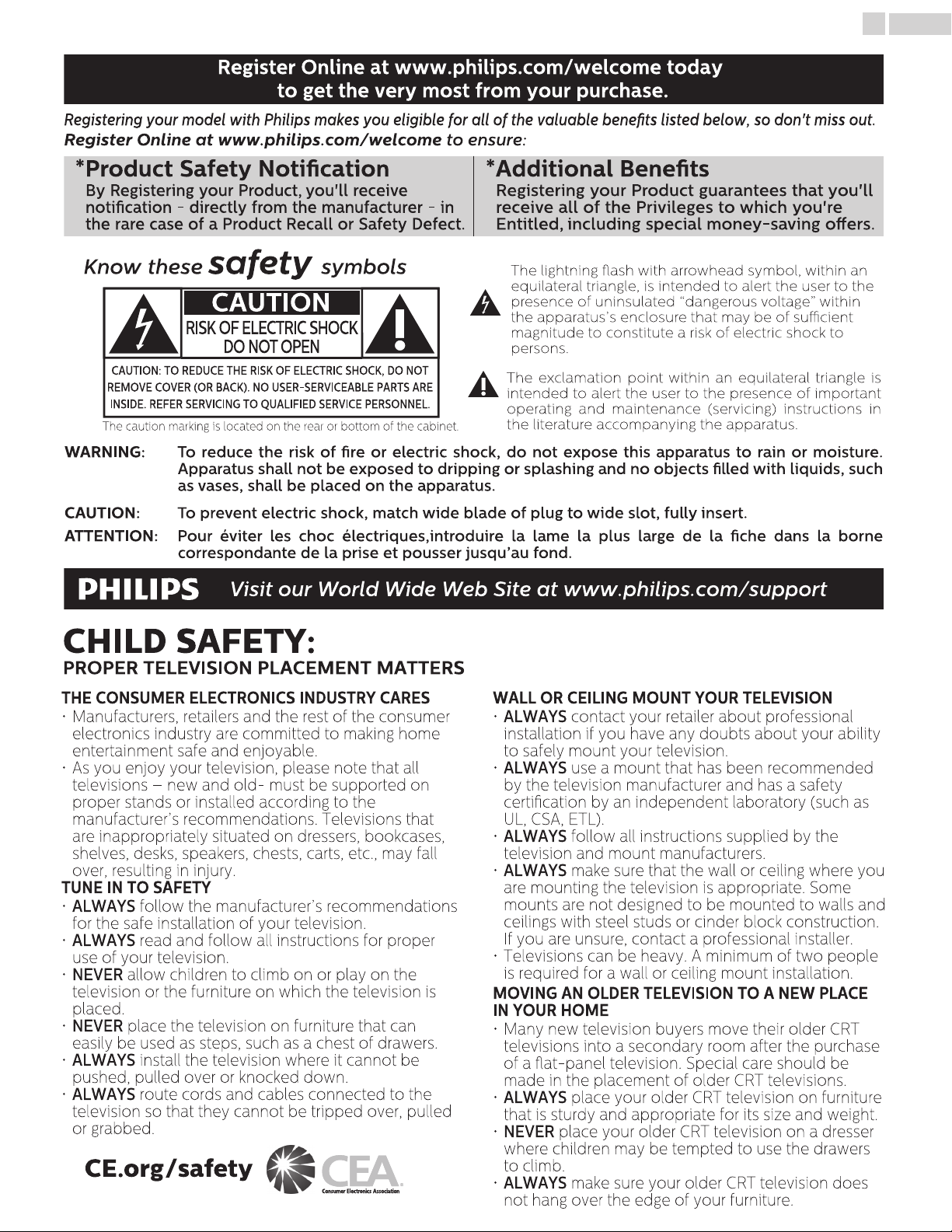
Know these safety symbols
The lightning ash with arrowhead symbol, within an
equilateral triangle, is intended to alert the user to the
presence of uninsulated “dangerous voltage” within
the apparatus’s enclosure that may be of sucient
magnitude to constitute a risk of electric shock to
persons.
The exclamation point within an equilateral triangle is
intended to alert the user to the presence of important
operating and maintenance (servicing) instructions in
the literature accompanying the apparatus.
CAUTION: TO REDUCE THE RISK OF ELECTRIC SHOCK, DO NOT
REMOVE COVER (OR BACK). NO USER-SERVICEABLE PARTS ARE
INSIDE. REFER SERVICING TO QUALIFIED SERVICE PERSONNEL.
RISK OF ELECTRIC SHOCK
DO NOT OPEN
The caution marking is located on the rear or bottom of the cabinet.
CAUTION
Registering your model with Philips makes you eligible for all of the valuable benets listed below, so don't miss out.
Register Online at www.philips.com/welcome to ensure:
Register Online at www.philips.com/welcome today
to get the very most from your purchase.
*Product Safety Notication *Additional Benets
By Registering your Product, you'll receive
notication - directly from the manufacturer - in
the rare case of a Product Recall or Safety Defect.
Registering your Product guarantees that you'll
receive all of the Privileges to which you're
Entitled, including special money-saving oers.
WARNING: To reduce the risk of re or electric shock, do not expose this apparatus to rain or moisture.
Apparatus shall not be exposed to dripping or splashing and no objects lled with liquids, such
as vases, shall be placed on the apparatus.
CAUTION: To prevent electric shock, match wide blade of plug to wide slot, fully insert.
ATTENTION: Pour éviter les choc électriques,introduire la lame la plus large de la che dans la borne
correspondante de la prise et pousser jusqu’au fond.
Visit our World Wide Web Site at www.philips.com/support
CHILD SAFETY:
PROPER TELEVISION PLACEMENT MATTERS
THE CONSUMER ELECTRONICS INDUSTRY CARES
• Manufacturers, retailers and the rest of the consumer
electronics industry are committed to making home
entertainment safe and enjoyable.
• As you enjoy your television, please note that all
televisions – new and old- must be supported on
proper stands or installed according to the
manufacturer’s recommendations. Televisions that
are inappropriately situated on dressers, bookcases,
shelves, desks, speakers, chests, carts, etc., may fall
over, resulting in injury.
TUNE IN TO SAFETY
• ALWAYS follow the manufacturer’s recommendations
for the safe installation of your television.
• ALWAYS read and follow all instructions for proper
use of your television.
• NEVER allow children to climb on or play on the
television or the furniture on which the television is
placed.
• NEVER place the television on furniture that can
easily be used as steps, such as a chest of drawers.
• ALWAYS install the television where it cannot be
pushed, pulled over or knocked down.
• ALWAYS route cords and cables connected to the
television so that they cannot be tripped over, pulled
or grabbed.
WALL OR CEILING MOUNT YOUR TELEVISION
• ALWAYS contact your retailer about professional
installation if you have any doubts about your ability
to safely mount your television.
• ALWAYS use a mount that has been recommended
by the television manufacturer and has a safety
certication by an independent laboratory (such as
UL, CSA, ETL).
• ALWAYS follow all instructions supplied by the
television and mount manufacturers.
• ALWAYS make sure that the wall or ceiling where you
are mounting the television is appropriate. Some
mounts are not designed to be mounted to walls and
ceilings with steel studs or cinder block construction.
If you are unsure, contact a professional installer.
• Televisions can be heavy. A minimum of two people
is required for a wall or ceiling mount installation.
MOVING AN OLDER TELEVISION TO A NEW PLACE
IN YOUR HOME
• Many new television buyers move their older CRT
televisions into a secondary room after the purchase
of a at-panel television. Special care should be
made in the placement of older CRT televisions.
• ALWAYS place your older CRT television on furniture
that is sturdy and appropriate for its size and weight.
• NEVER place your older CRT television on a dresser
where children may be tempted to use the drawers
to climb.
• ALWAYS make sure your older CRT television does
not hang over the edge of your furniture.
CE.org/safety
3 .English
Important Safety Instructions
1. Read these instructions.
2. Keep these instructions.
3. Heed all warnings.
4. Follow all instructions.
5. Do not use this apparatus near water.
6. Clean only with dry cloth.
7. Do not block any ventilation openings. Install in
accordance with the manufacturer’s instructions.
8. Do not install near any heat sources such as
radiators, heat registers, stoves, or other apparatus
(including ampliers) that produce heat.
9. Do not defeat the safety purpose of the polarized
or grounding type plug. A polarized plug has two
blades with one wider than the other. A grounding
type plug has two blades and a third grounding
prong. The wide blade or the third prong are
provided for your safety. If the provided plug does
not t into your outlet, consult an electrician for
replacement of the obsolete outlet.
10. Protect the power cord from being walked on or
pinched particularly at plugs, convenience
receptacles, and the point where they exit from
the apparatus.
1 1. Only use attachments / accessories specied by
the manufacturer.
12. Use only with the cart, stand,
tripod, bracket, or table specied
by the manufacturer, or sold with
the apparatus. When a cart is
used, use caution when moving
the cart / apparatus combination
to avoid injury from tip-over.
13. Unplug this apparatus during lightning storms or
when unused for long periods of time.
14. Refer all servicing to qualied service personnel.
Servicing is required when the apparatus has
been damaged in any way, such as
power-supply cord or plug is damaged, liquid
has been spilled or objects have fallen into the
apparatus, the apparatus has been exposed to
rain or moisture, does not operate normally, or
has been dropped.
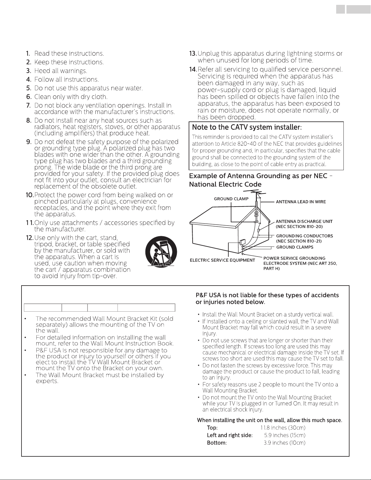
Note to the CATV system installer:
This reminder is provided to call the CATV system installer’s
attention to Article 820-40 of the NEC that provides guidelines
for proper grounding and, in particular, species that the cable
ground shall be connected to the grounding system of the
building, as close to the point of cable entry as practical.
Example of Antenna Grounding as per NEC National Electric Code
ANTENNA LEAD IN WIRE
GROUND CLAMP
ANTENNA DISCHARGE UNIT
(NEC SECTION 810-20)
ELECTRIC SERVICE EQUIPMENT
GROUNDING CONDUCTORS
(NEC SECTION 810-21)
POWER SERVICE GROUNDING
ELECTRODE SYSTEM (NEC ART 250,
PART H )
GROUND CLAMPS
• The recommended Wall Mount Bracket Kit (sold
separately) allows the mounting of the TV on
the wall.
• For detailed information on installing the wall
mount, refer to the Wall Mount Instruction Book.
• P&F USA is not responsible for any damage to
the product or injury to yourself or others if you
elect to install the TV Wall Mount Bracket or
mount the TV onto the Bracket on your own.
• The Wall Mount Bracket must be installed by
experts.
P&F USA is not liable for these types of accidents
or injuries noted below.
• Install the Wall Mount Bracket on a sturdy vertical wall.
• If installed onto a ceiling or slanted wall, the TV and Wall
Mount Bracket may fall which could result in a severe
injury.
• Do not use screws that are longer or shorter than their
specied length. If screws too long are used this may
cause mechanical or electrical damage inside the TV set. If
screws too short are used this may cause the TV set to fall.
• Do not fasten the screws by excessive force. This may
damage the product or cause the product to fall, leading
to an injury.
• For safety reasons use 2 people to mount the TV onto a
Wall Mounting Bracket.
• Do not mount the TV onto the Wall Mounting Bracket
while your TV is plugged in or Turned On. It may result in
an electrical shock injury.
When installing the unit on the wall, allow this much space.
Top: 1 1.8 inches (30cm)
Left and right side: 5.9 inches (15cm)
Bottom: 3.9 inches (10cm)
4 .English
Wall Mount Bracket Kit
Brand Model # Screw dimension
65PFL8900 SANUS VMPL3 M6 x 0.629” (16mm)
1 Notice
Trademarks are the property of Koninklijke Philips N.V. or
their respective owners.
P&F USA reserves the right to change products at any time
without being obliged to adjust earlier supplies accordingly.
The material in this manual is believed adequate for the
intended use of the system. If the product or its individual
modules or procedures are used for purposes other than
those specied herein, conrmation of their validity and
suitability must be obtained. P&F USA warrants that the
material itself does not infringe any United States patents.
No further warranty is expressed or implied.
P&F USA cannot be held responsible neither for any errors
in the content of this document nor for any problems as a
result of the content in this document. Errors reported to
P&F USA will be adapted and published on the P&F USA
support website as soon as possible.
Pixel characteristics
This LCD product has a high number of color pixels.
Although it has eective pixels of 99.999% or more, black
dots or bright points of light (red, green or blue) may
appear constantly on the screen. This is a structural
property of the display (within common industry standards)
and is not a malfunction.
Warranty
No components are user serviceable. Do not open or
remove covers to the inside of the product. Repairs may
only be done by Service Centers and ocial repair shops.
Failure to do so shall void any warranty, stated or implied.
Any operation expressly prohibited in this manual, any
adjustments or assembly procedures not recommended or
authorized in this manual shall void the warranty.
Federal Communications Commission Notice
This equipment has been tested and found to comply with
the limits for a Class B Digital device, pursuant to part 15 of
the FCC Rules. These limits are designed to provide
reasonable protection against harmful interference in a
residential installation. This equipment generates, uses and
can radiate radio frequency energy and, if not installed and
used in accordance with the instructions, may cause
harmful interference to radio communications. However,
there is no guarantee that interference will not occur in a
particular installation. If this equipment does cause
harmful interference to radio or television reception, which
can be determined by turning the equipment o and on,
the user is encouraged to try to correct the interference by
one or more of the following measures:
• Reorient or relocate the receiving antenna.
• Increase the separation between the equipment and
the receiver.
• Connect the equipment into an outlet on a circuit
dierent from that to which the receiver is connected.
• Consult the dealer or an experienced radio or
television technician for help.
Modications
This apparatus may generate or use radio frequency energy.
Changes or Modications to this apparatus may cause
harmful interference.
Any Modications to the apparatus must be Approved by
P&F USA.
The user could lose the authority to operate this apparatus if
an unauthorized Change or Modication is made.
Cables
Connections to this device must be made with shielded
cables with metallic RFI / EMI connector hoods to maintain
compliance with FCC Rules and Regulations.
Canadian notice
CAN ICES-3 (B)/NMB-3 (B)
Analog and Digital Television Receiving Apparatus, Canada
BETS-7 / NTMR-7.
LASER SAFETY
This apparatus is classied as a CLASS I
LASER PRODUCT. This apparatus employs
a laser. Only a qualied service person
should remove the cover or attempt to
service this apparatus, due to possible eye injury.
CAUTION: Use of controls or adjustments or performance of
procedures other than those specied herein may
result in hazardous radiation exposure.
The following FCC/IC RSS is description of
Wireless LAN adapter.
FCC Caution: Any changes or modications not
expressly approved by the party responsible for
compliance could void the user’s authority to operate
this equipment.
This transmitter must not be co-located or operating in
conjunction with any other antenna or transmitter.
Country Code Statement
For product available in the USA market, only channel 1∼1 1
can be operated. Selection of other channels is not
possible.
To maintain compliance with FCC RF exposure
requirements, use only belt-clips, holsters or similar
accessories that do not contain metallic components in
its assembly. The use of accessories that do not satisfy
these requirements may not comply with FCC RF
exposure requirements and should be avoided.
This device complies with Industry Canada
license-exempt RSS standard(s). Operation is subject
to the following two conditions: (1) this device may not
cause interference and (2) this device must accept any
interference, including interference that may cause
undesired operation of the device.
5150-5250 MHz band is restricted to indoor
operations only.
High-power radars are allocated as primary users (i.e.
priority users) of the bands 5250-5350 MHz and
5650-5850 MHz and that these radars could cause
interference and/or damage to LE-LAN devices.
Compliance with IC requirement RSS-210 A9.4.4
Data transmission is always initiated by software,
which is the passed down through the MAC, through
the digital and analog baseband, and nally to the RF
chip. Several special packets are initiated by the MAC.
These are the only ways the digital baseband portion
will turn on the RF transmitter, which it then turns o
at the end of the packet. Therefore, the transmitter will
be on only while one of the aforementioned packets
is being transmitted. In other words, this device
automatically discontinue transmission in case of
either absence of information to transmit or
operational failure.
5
.English
Declaration of Conformity
Trade Name : PHILIPS
Responsible Party : P&F USA, Inc.
Model : 65PFL8900
Address : PO Box 2248, Alpharetta, GA 30023-2248 U.S.A.
Telephone Number : 1 866 226 1568

Copyright
All other registered and unregistered trademarks are the
property of their respective owners.
The terms HDMI and HDMI
High-Denition Multimedia
Interface, and the HDMI Logo
are trademarks or registered
trademarks of HDMI Licensing
LLC in the United States and
other countries.
Manufactured under license
from Dolby Laboratories. Dolby
and the double-D symbol are
trademarks of Dolby
Laboratories.
Sonic Emotion and the Sonic
Emotion logo symbol are
registered trademarks of sonic
emotion ag.
The CEA 4K Ultra HD Certication
Logo is a U.S. registered mark.
Netix is available in certain countries.
Streaming membership required.
More information at www.netix.com.
VUDUTM is a trademark of
VUDU, Inc.
YouTube and the YouTube logo
are trademarks of Google Inc.
PANDORA, the PANDORA logo,
and the Pandora trade dress
are trademarks or registered
trademarks of Pandora Media,
Inc. Used with permission.
The Wi-Fi CERTIFIED Logo is a
certication mark of the Wi-Fi
Alliance.
CinemaNow and the
CinemaNow logo are
trademarks of BestBuy Stores
L.P. and BestBuy Canada LTD.
Portico, Portico TV and the
Portico Free TV logo are service
marks of Net2TV Corporation.
Portions of this software are copyright © The FreeType Project
(www.freetype.org).
The American Academy of Pediatrics discourages television
viewing for children younger than two years of age.
6 .English
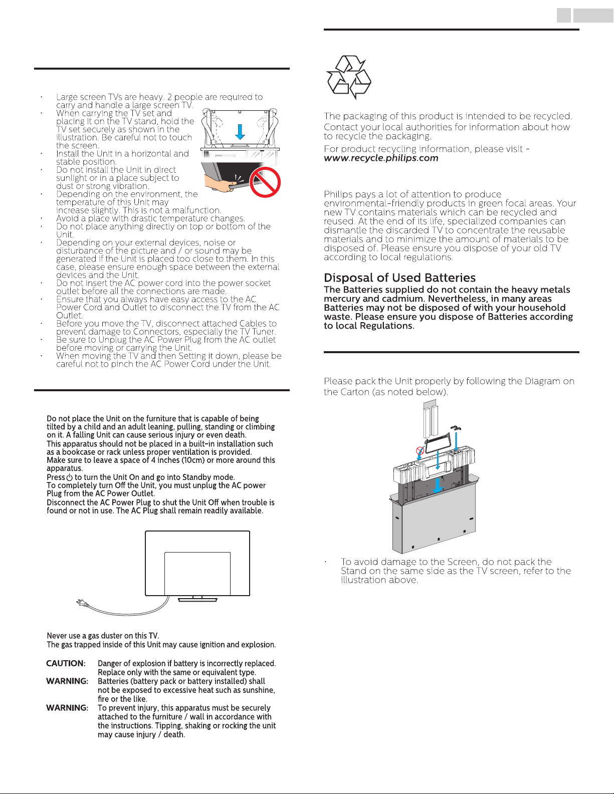
• Large screen TVs are heavy. 2 people are required to
carry and handle a large screen TV.
• When carrying the TV set and
placing it on the TV stand, hold the
TV set securely as shown in the
illustration. Be careful not to touch
the screen.
• Install the Unit in a horizontal and
stable position.
• Do not install the Unit in direct
sunlight or in a place subject to
dust or strong vibration.
• Depending on the environment, the
temperature of this Unit may
increase slightly. This is not a malfunction.
• Avoid a place with drastic temperature changes.
• Do not place anything directly on top or bottom of the
Unit.
• Depending on your external devices, noise or
disturbance of the picture and / or sound may be
generated if the Unit is placed too close to them. In this
case, please ensure enough space between the external
devices and the Unit.
• Do not insert the AC power cord into the power socket
outlet before all the connections are made.
• Ensure that you always have easy access to the AC
Power Cord and Outlet to disconnect the TV from the AC
Outlet.
• Before you move the TV, disconnect attached Cables to
prevent damage to Connectors, especially the TV Tuner.
• Be sure to Unplug the AC Power Plug from the AC outlet
before moving or carrying the Unit.
• When moving the TV and then Setting it down, please be
careful not to pinch the AC Power Cord under the Unit.
Do not place the Unit on the furniture that is capable of being
tilted by a child and an adult leaning, pulling, standing or climbing
on it. A falling Unit can cause serious injury or even death.
This apparatus should not be placed in a built-in installation such
as a bookcase or rack unless proper ventilation is provided.
Make sure to leave a space of 4 inches (10cm) or more around this
apparatus.
Press to turn the Unit On and go into Standby mode.
To completely turn O the Unit, you must unplug the AC power
Plug from the AC Power Outlet.
Disconnect the AC Power Plug to shut the Unit O when trouble is
found or not in use. The AC Plug shall remain readily available.
AC Power Plug
Never use a gas duster on this TV.
The gas trapped inside of this Unit may cause ignition and explosion.
CAUTION:
Danger of explosion if battery is incorrectly replaced.
Replace only with the same or equivalent type.
WARNING:
Batteries (battery pack or battery installed) shall
not be exposed to excessive heat such as sunshine,
re or the like.
WARNING:
To prevent injury, this apparatus must be securely
attached to the furniture / wall in accordance with
the instructions. Tipping, shaking or rocking the unit
may cause injury / death.
The packaging of this product is intended to be recycled.
Contact your local authorities for information about how
to recycle the packaging.
For product recycling information, please visit -
www.recycle.philips.com
Philips pays a lot of attention to produce
environmental-friendly products in green focal areas. Your
new TV contains materials which can be recycled and
reused. At the end of its life, specialized companies can
dismantle the discarded TV to concentrate the reusable
materials and to minimize the amount of materials to be
disposed of. Please ensure you dispose of your old TV
according to local regulations.
Disposal of Used Batteries
The Batteries supplied do not contain the heavy metals
mercury and cadmium. Nevertheless, in many areas
Batteries may not be disposed of with your household
waste. Please ensure you dispose of Batteries according
to local Regulations.
Please pack the Unit properly by following the Diagram on
the Carton (as noted below).
• To avoid damage to the Screen, do not pack the
Stand on the same side as the TV screen, refer to the
illustration above.
7 .English
2 Important
Positioning the TV
Environmental Care
End of Life Directives
Regulatory Notices
Preparing to Move/Ship the Unit
865PFL8900
AAA
AAA
SizeQuantityModel
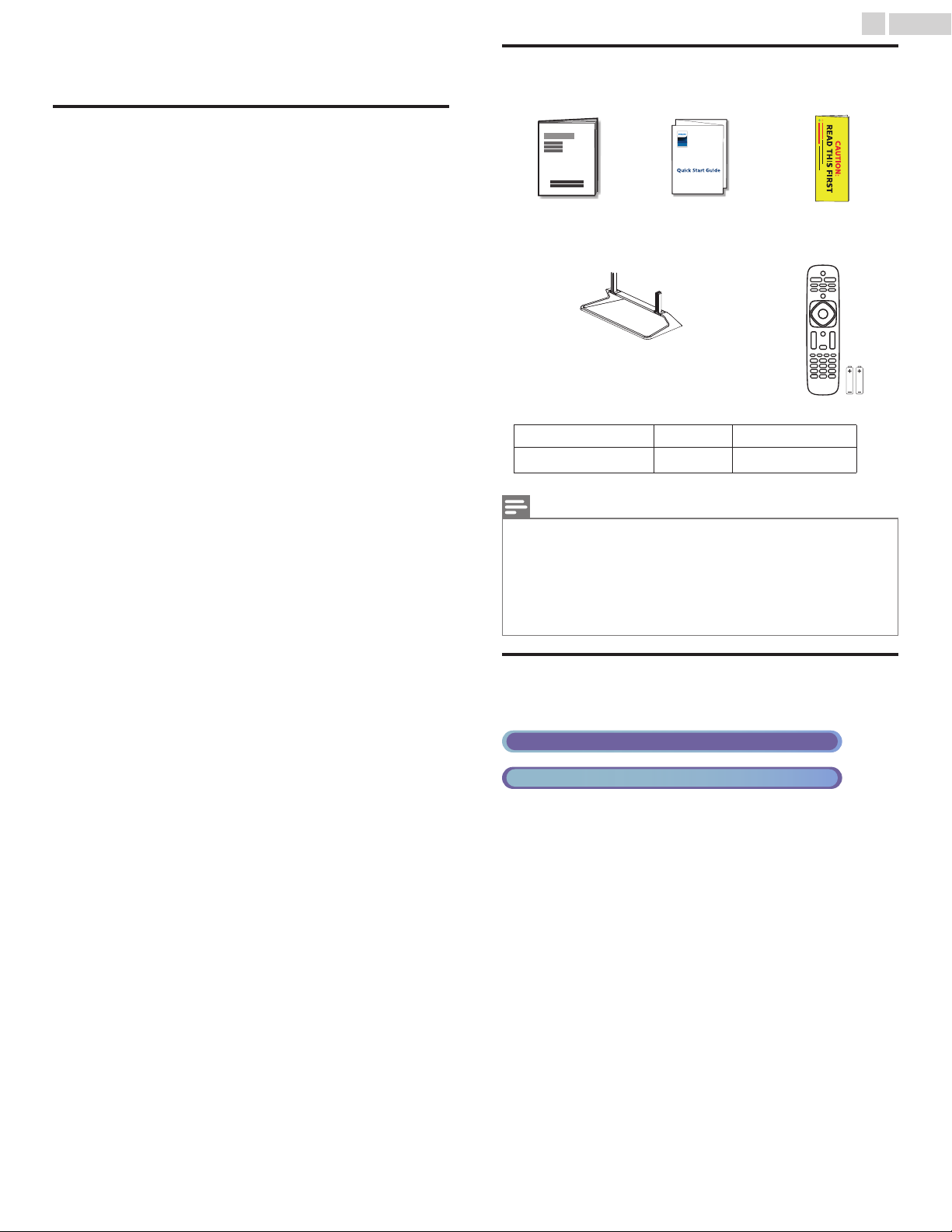
Screws packed with this Unit.
TV base and Screws
Quick Start guideUser Manual
(AAA, 1.5V x 2)
Remote Control
and Batteries
Caution Sheet
M4 x 0.393”(10mm)
Digital TV Operation
Cable / NTSC (Analog) TV Operation
8
.English
3 Getting Started
Features
DTV / Analog TV / CATV
•
You can use your Remote Control to Select channels which are Broadcast in Digital format and
conventional Analog format. Also, Cable and Satellite subscribers can access their TV channels.
Information display
•
You can display on the TV screen the Title, contents (DTV only) and other information on the
current Program.
Autoprogram
•
This Unit Automatically scans and memorizes channels available in your area, Eliminating difficult
Setup procedures.
Net TV
•
This unit lets you enjoy Internet services. Use the remote control to browse the Net TV pages. You
can play movies and much more, all from your TV screen.
Child lock
•
This feature allows you to Block children’s access to inappropriate Programs.
Closed Caption decoder
•
Built-in Closed Caption decoder displays text for Closed Caption supported Programs.
MTS / SAP tuner
•
Audio can be selected from the Remote Control.
Auto Standby
•
If there is No Input Signal and No Operation for 15 minutes, the Unit will go into Standby mode
Automatically.
Sleep Timer
•
You can set the Unit to go into Standby mode after a specific amount of time.
Choices for On-screen language
•
Select your On-screen language: English, Spanish or French.
Stereo sound function
•
PLL frequency synthesized tuning
•
Provides free and easy channel selection and lets you tune directly to any channel using the
number and decimal point “•” keys on the Remote Control.
Various adjustments for Picture and Sound
•
Customizes picture quality suitable for your room and sets your sound preference.
EasyLink via HDMI link
•
EasyLink allows your other HDMI link devices to be controlled by the HDMI cable connected to
your TV.
HDMI Input
•
HDMI-DVI Input
•
If your Video Device has a DVI Output jack, use an HDMI-DVI Conversion Cable to connect the
Unit.
Component Video Input
•
PC Input
•
AV Input
•
Audio and Video Input from an External Device.
USB terminal
•
The Picture, Music and Video files stored on a USB Memory Stick can be played back on this
unit.
Digital Audio Output
•
Headphone Audio Output
•
Headphone 3.5mm Stereo jack for personal listening.
Supplied Accessories
Note(s)
If you lose the Screws, please purchase the above-mentioned Phillips head Screws at your local
•
store.
If you need to replace these accessories, please refer to the part name or No. with the illustrations
•
and call our toll free customer support line found on the cover of this User Manual.
When using a Universal Remote Control to operate this Unit.
Make sure the component code on your Universal Remote Control is set to our brand. Refer to
•
the instruction book accompanying your Remote Control for more details.
We Do Not guarantee 100% interoperability with All Universal Remote Controls.
•
Symbols used in this User Manual
The following is the description for the symbols used in this User Manual.
Description refers to:
If neither symbol appears, the operation is applicable to both.
•
Continued on next page.
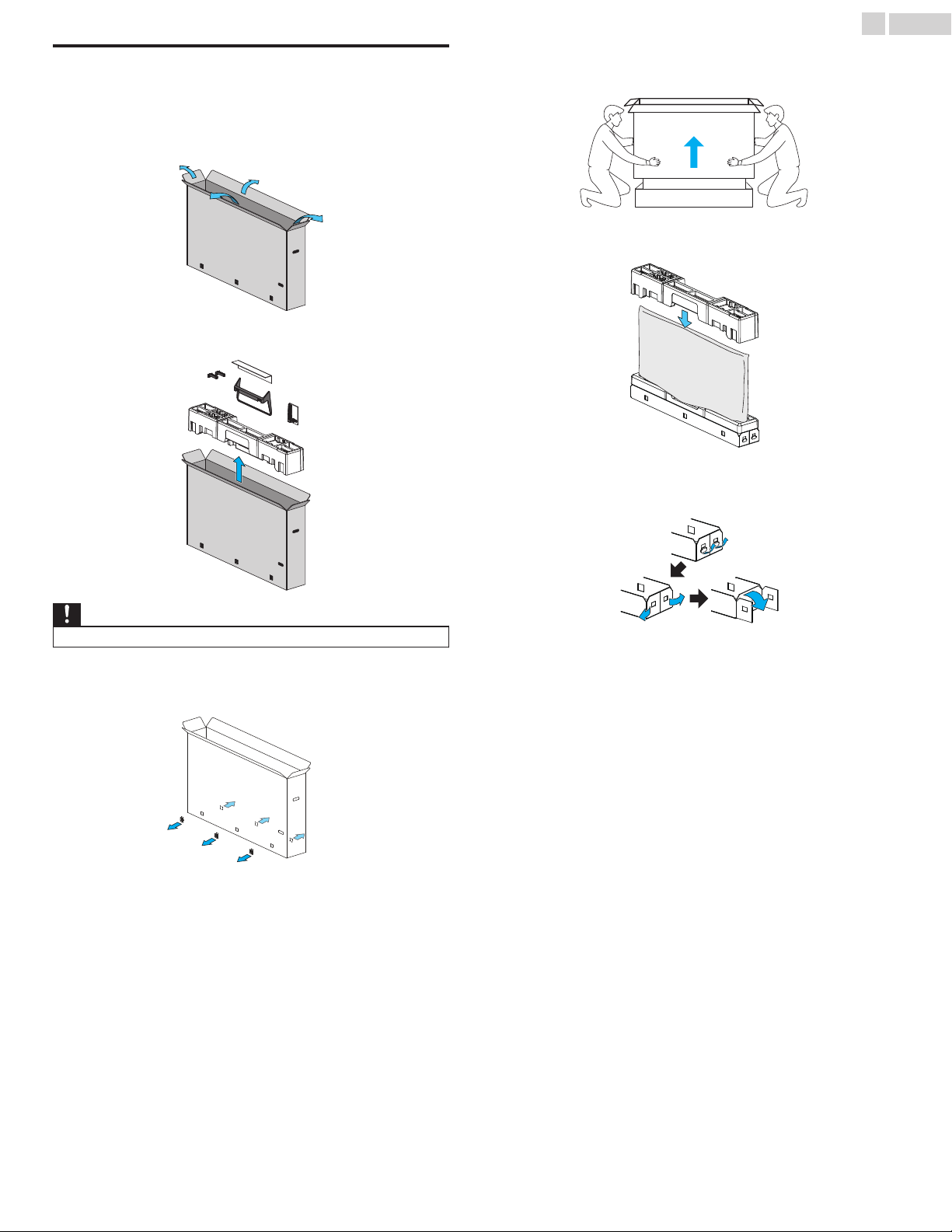
Unpacking
It is recommended that two or more people remove the TV set from the
box. Be careful not to injure your fingers and keep children away during
assembly.
Open the top flaps of the box.
1
Remove all Accessories.
2
Remove the outer slipbox with care.
4
Put the top polystyrene foam base back in its original position.
5
Unhinge the retaining tabs and unfold the left and right side of the
6
bottom packaging.
9
.English
Caution(s)
DO NOT take the TV set out of the box yet.
•
Remove the packing joints from the box.
3
Continued on next page.
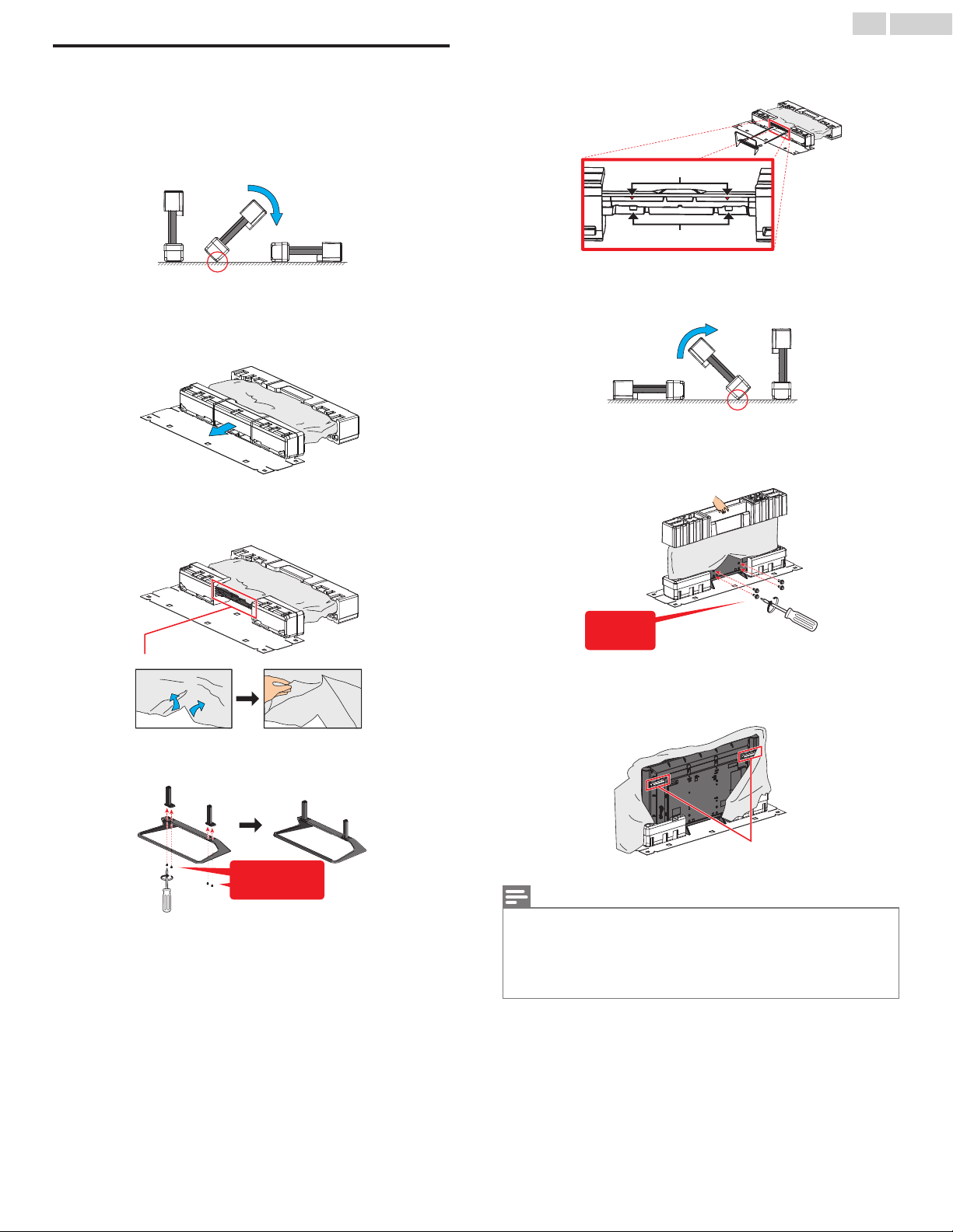
Installing the Stands
supporting point
plastic bag
2 screws each
required
stand slots
stand slot guides
supporting point
4 screws
required
handles
You must Support the top of the TV set at all times to prevent the TV from
falling.
Carefully tilt and lay the TV set with the cautionary note on the plastic
1
bag upward and its rear panel down as shown in the illustration. This
requires two or more people.
Remove the center base of the three bottom polystyrene foam
2
bases.
Insert the support pillars of the stand into the bottom of the TV all the
5
way to the end of the stand slots.
Carefully raise the TV set as shown in the illustration. This requires two
6
or more people.
Rip the plastic bag to make it easy to tighten screws.Tighten screws.
7
10 .English
From the center bottom part, rip the plastic bag to expose the bottom
3
of the TV set.
Assemble the stand.
4
Remove the top polystyrene foam base and the plastic bag to expose
8
the handles.
Note(s)
A wide open space is recommended for assembly.
•
A Phillips-head screwdriver is required to fasten the stands to the TV set.
•
When attaching the Stand, ensure that All Screws are tightly fastened. If the Stand is not properly
•
attached, it could cause the Unit to fall, resulting in injuries as well as damage to the Unit.
To remove the Stand from this Unit, unscrew the Phillips-head screws by reversing the
•
procedure. Be careful not to drop the Stand when you remove it.
Continued on next page.
11 .English
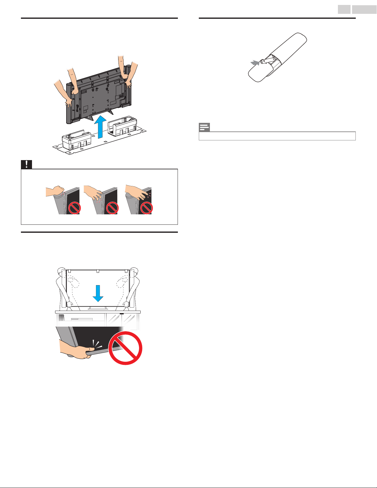
Lifting
Grip each handle on the rear panel with a hand, support the TV set with
the other hand, then lift it from the bottom polystyrene foam bases. This
requires two or more people.
Caution(s)
When lifting up the TV set, do not grab the speaker top, speaker mesh, or touch the screen.
•
Installing the Remote Control Batteries
Slide the battery cover off the back of the Remote Control.
1
Insert 2 Supplied Batteries (AAA, 1.5V). Be sure the + and – ends of the
2
Batteries line up with the markings inside the case.
Slide the cover back into position.
3
Note(s)
Remove the Batteries if not using the Remote Control for an extended period of time.
•
Moving
When carrying the TV set and placing it on the TV stand, hold the TV set
securely as shown in the illustration. Be careful not to touch the screen.
Continued on next page.
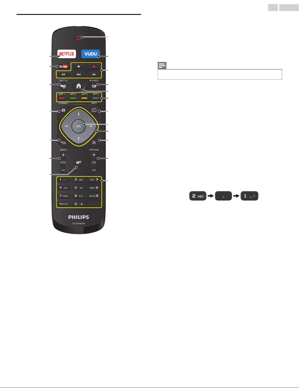
Remote Control
o
p
s
r
q
n
m
b
a
c
d
g
e
h
k
f
l
j
i
a
B (POWER)
Turns the TV On from Standby or Off to Standby.
VUDU
b
Access directly to VUDU.
EasyLink (HDMI CEC) buttons
c
JJ / KK
K F
C
Note(s)
Pause may not work properly on some devices even if they are EasyLink (HDMI CEC)
•
compliant.
d
b SOURCE
Selects Connected devices.
e
a (Home)
Displays the main menu.
Apps (APP1 / APP2 / APP3 / APP4) buttons
f
Works as direct access to user specified net apps.
g
T INFO
Displays Information about the current program.
OK
h
Press to decide the command of setting when the Home menu is
displayed.
i
H I J K (NAVIGATION buttons)
Moves the cursor, Selects the On-screen Menu items.
j
f OPTIONS
Displays a list of menu items applicable to the highlighted object or
screen.
CH + / –
k
Selects a Channel.
0 - 9 (NUMBER buttons)
l
Used to enter a Channel / Program number.
• (DOT) : Use with 0-9 to Select digital channels. For example, to
: Searches Backward or Forward through the disc.
: Starts, pauses or resumes playback.
: Stops the Disc playback.
enter 2.1, press
12
.English
PREV.CH : Returns to the previously viewed Channel.
m
d (MUTE)
Turns the Sound On and Off.
VOL + / –
n
Adjusts the Volume.
o
e BACK
Returns to the previous Menu operation.
p
R FORMAT
Adjusts the Picture size on the TV screen.
q
c NET TV
Access to Net TV menu directly.
YOUTUBE
r
Access directly to YouTube.
NETFLIX
s
Access directly to Netflix.
Continued on next page.
f
g
h
d
e
c
b
a
o
p
q
j
i
m
k
l
n
13
.English
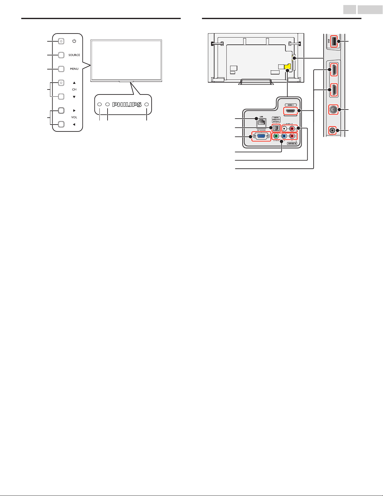
Control Panel
a
B (POWER)
Turns the TV On and Off.
SOURCE
b
Selects Connected devices.
MENU
c
Opens the Main On-screen Menu.
d
CH H / I
Selects a Channel. In the Menu screen, moves the Cursor
Up (H)/Down (I).
e
VOL J / K
Adjusts the Volume. In the Menu screen, moves the Cursor
Left (J) / Right (K).
VOL J
VOL K
Remote Control Sensor
f
Receives IR signal from Remote control.
Ambient Light Sensor
g
Alters the brightness of the TV screen automatically by detecting your
room lighting level. Do not block this Light Sensor window which
allows proper operation.
Power On / Standby Indicator
h
(On : lights in white, Standby : no light)
: Volume Down
: Volume Up
Terminals
Ethernet port
i
For Internet connection using an Ethernet Cable with an RJ-45
connector.
Digital Audio Output jack
j
Digital Audio (S/PDIF) Output to home theaters and other Digital
Audio systems.
PC Input jack
k
VGA cable connection for PC.
Component (Y/Pb/Pr) / Composite Video (VIDEO) Input jack(s) for
l
VIDEO
Composite Video Input (VIDEO) jack is a shared jack with Component
Video Input (Y) jack.
Analog Audio (L/R) Input jacks
m
Connect Analog Audio signals from;
–HDMI-DVI / Analog Audio (L/R) jacks signal
–Component Video / Analog Audio (L/R) jacks signal
–Composite Video / Analog Audio (L/R) jacks signal
–PC Connection / Analog Audio (L/R) jacks signal with Stereo mini
3.5mm plug Audio cable on PC
HDMI Input jack(s)
n
Digital Audio and Video Input from high definition Digital devices such
as DVD / Blu-ray disc players, Cable / Satellite Set-top Boxes, PC’s,
etc.
* For HDMI 1 only
In addition to normal HDMI and HDMI-DVI functionality, it outputs
TV Audio to an HDMI-ARC-compliant device, such as a home
theater system.
USB terminal
o
Data Input from USB Memory Stick only.
Do not connect any device to this terminal such as Digital camera,
keyboard, mouse, etc.
75 ohm Cable / Antenna connection
p
Signal Input from an Antenna or Cable / Satellite Set-top Boxes.
Headphone Audio Output jack
q
Headphone 3.5mm stereo jack for personal listening.
Continued on next page.
INININ
OUT
RF cable
Antenna
Cable
INININ
Antenna
Set-top Box
RF cable
OUT
IN
RF cable
IN
IN
IN
IN
OUT
Set-top Box
RF cable
HDMI cable
HDMI cable
HDMI cable
Set-top Box
Set-top Box
Set-top Box
IN
IN
IN
RF cable
RF cable
RF cable
OUT
OUT
OUT
Component (Y/Pb/Pr)
Video cables
Component (Y/Pb/Pr)
Video cables
Component (Y/Pb/Pr)
Video cables
IN
IN
IN
OUT
OUT
OUT
Audio (L/R) cables
Audio (L/R) cables
Audio (L/R) cables
IN
IN
IN
Cable
OUT
RF cable
RF cable
RF cable
IN
IN
IN
OUT
Audio (L/R) +
Video cables
IN
OUT
Audio (L/R) + Video cables
Audio (L/R) + Video cables
Audio (L/R) + Video cables
IN
IN
IN
OUTOUT
RF cable
IN
Satellite
IN
Cable
Set-top Box
Blu-ray disc/DVD recorder
14 .English
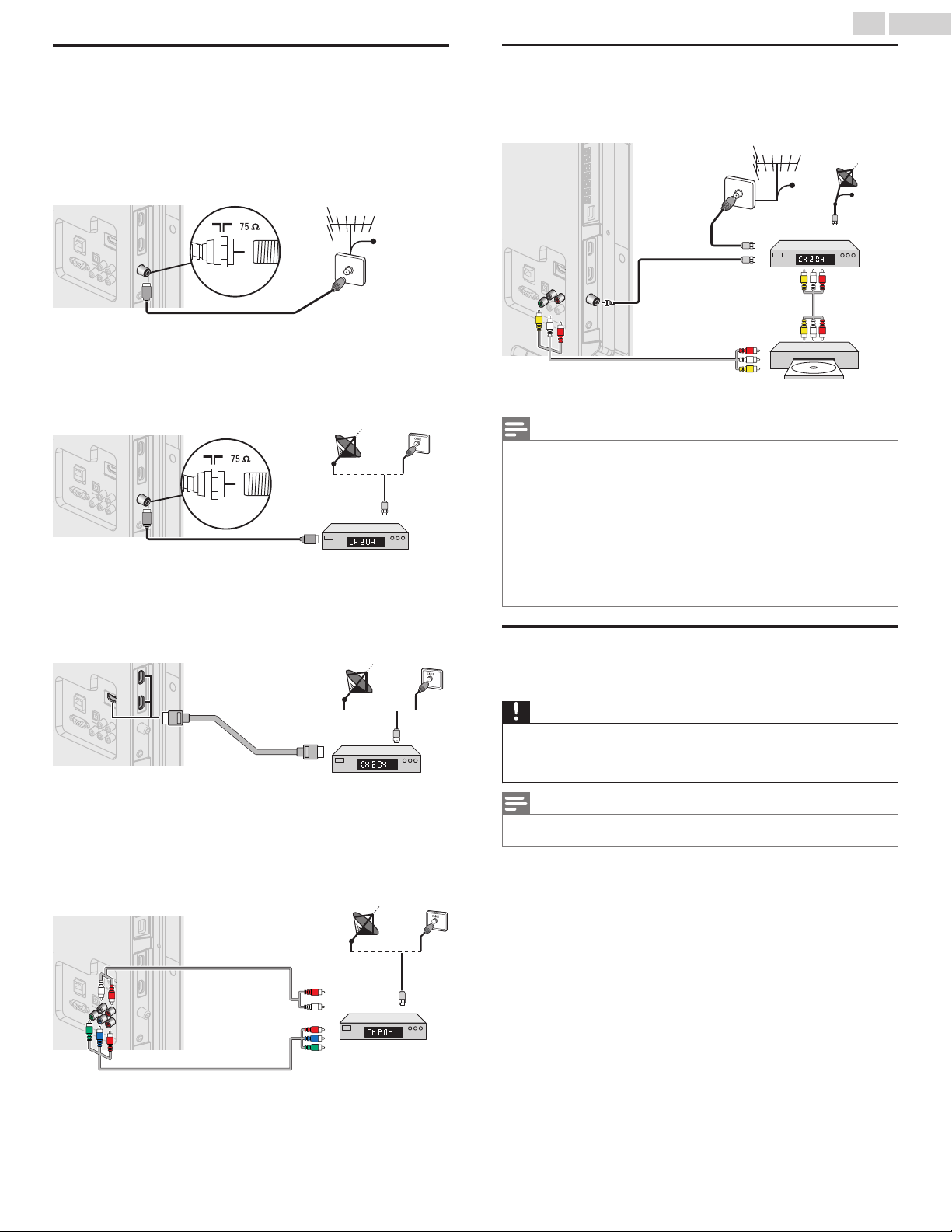
Connecting Antenna or Cable / Satellite / IPTV Set-top Box
Be sure your Antenna or another Device is connected properly before
plugging in the AC Power Cord.
If connecting to an Antenna through an RF cable
Any DTV Programs that are Broadcast in your area can be received for free
through an Antenna Connection.
If connecting Cable / Satellite / IPTV Set-top Box using an RF
cable
If the TV is connected to a Cable or Set-top Box via a Coaxial Connection,
set the TV to channel 3/4 or the channel specified by the service
provider.
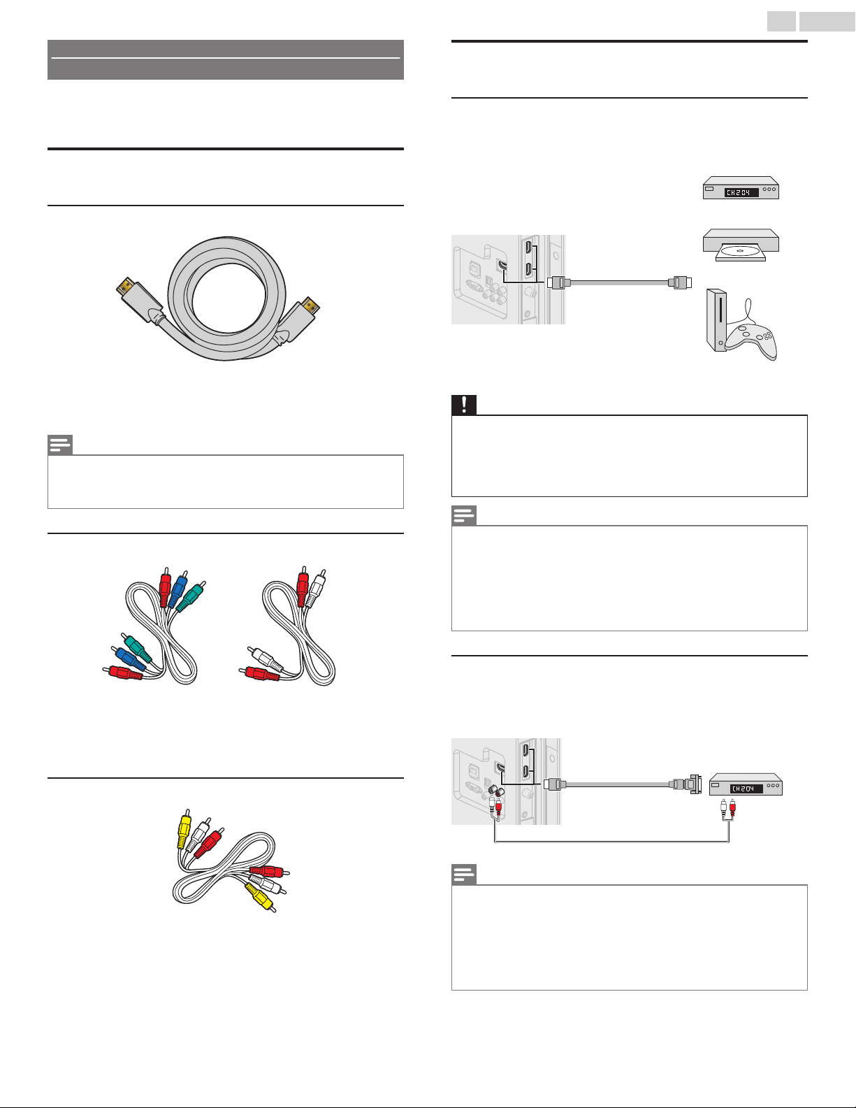
If connecting Cable / Satellite / IPTV Set-top Box using an HDMI
cable
If the TV is connected to a Cable / Satellite Set-top Box via an HDMI cable,
make sure you select the correct Source by using b SOURCE.
Connecting a Cable / Satellite / IPTV Set-top Box, Bluray Disc / DVD Recorder via Composite Connectors and
Analog Audio
Do Not place your Recorder too close to the Screen because some
Recorders can be susceptible to harmful interference from the TV.
Note(s)
If you have any question about the DTV’s Antenna, visit
•
information.
Depending on your Antenna system, you may need different types of combiners (mixers) or
•
separators (splitters) for HDTV Signal. The minimum RF bandpass on these Devices is 2,000MHz
or 2GHz.
For your safety and to avoid damage to this Unit, please unplug the RF Coaxial Cable from the
•
Antenna Input jack before moving the Unit.
If you did use an Antenna to receive Analog TV, it should also work for DTV reception. Outdoor
•
or attic Antennas will be more effective than a Set-top Box or inside Antenna.
To Turn On your reception source easily between Antenna and Cable, Install an Antenna
•
selector.
If you are not receiving a Signal from your Cable service, contact the Cable provider.
•
www.antennaweb.org
for further
Plugging in the AC Power Cord
Make sure that the AC power cord must be plugged to an AC outlet after
all the necessary connections are made.
If connecting Cable / Satellite / IPTV Set-top Box using
Component Video Input
If the TV is connected to a Cable / Satellite Set-top Box via Component
Video Input, make sure you select the correct Component Video Source
by using b SOURCE.
Caution(s)
Connect the Analog Audio signal cables from Set-top Box or player to the Analog Audio L/R
•
Input jacks.
Or if you have an amplifier, connect the HDMI cable to the HDMI input via your amplifier.
If you have an amplifier, connect the HDMI cable to the HDMI input via your amplifier.
•
Note(s)
Each time you plug in the AC Power Cord, no operations will be performed for several seconds.
•
This is not a malfunction.
Continued on next page.
HD game console
or
Blu-ray Disc/DVD Player
or
Set-top Box
OUT
IN
IN
IN
HDMI cable
HDMI cable
HDMI cable
Cable Receiver or
Satellite Set-top Box with
the DVI Output jack
OUT
HDMI-DVI
conversion cable
HDMI-DVI
conversion cable
HDMI-DVI
conversion cable
IN
IN
IN
OUT
Audio (L/R) cables
IN
IN
IN
15 .English
No supplied cables are used with these connections:
Please purchase the Necessary Cables at your local store.
•
Before you connect the AC Power Cord:
Be sure other Devices are connected properly before plugging in the AC
Power Cord.
Selecting your Connection quality
HDMI - Highest quality
Supports high-definition Digital signals and gives highest picture and
sound quality. Video and Audio signals are combined in one cable. You
must use HDMI for full high-definition Video and to enable EasyLink(HDMI
CEC).
Note(s)
Philips HDMI supports HDCP (High-bandwidth Digital Contents Protection). HDCP is a form of
•
Digital Rights Management that protects high definition content in Blu-ray discs or DVDs.
The HDMI-ARC connector on the TV features HDMI-ARC functionality. This allows output of TV
•
Audio to an HDMI-ARC-compliant Device.
Component (Y Pb Pr) - High quality
Connecting your Devices
HDMI Digital Connection
HDMI Connection offers the Highest Picture quality.
HDMI (High-Definition Multimedia Interface) transports High-Definition
Digital Video and multi-channel Digital Audio through a single cable.
Caution(s)
No sound is heard when using the HDMI Digital Connection.
Connect the Analog Audio signal cables from Set-top Box or player to the Analog Audio L/R
•
Input jacks.
Or if you have an amplifier, connect the HDMI cable to the HDMI input via your amplifier.
No sound with distorted picture occurs when using the HDMI Digital Connection.
If you have an amplifier, connect the HDMI cable to the HDMI input via your amplifier.
•
Note(s)
Some HDMI cables and devices may not be compatible with the TV due to different HDMI
•
specifications.
Use an HDMI cable with the HDMI logo (a certified HDMI cable). High Speed HDMI cable is
•
recommended for the Better compatibility.
The Unit accepts 480i / 480p / 720p / 1080i, 1080p, 2160p 24/30/60Hz of Video signals,
•
32kHz / 44.1kHz and 48kHz of Audio signals.
This Unit accepts LPCM, AC-3, DD+ Audio signal.
•
This Unit accepts only signals in compliance with EIA861.
•
Supports High-Definition Analog signals but gives lower picture quality
than HDMI. Component (Y/Pb/Pr) Video cables combine red / green /
blue Video cables with red / white Audio (L/R) Cables. Match the cable
colors when you connect to the TV.
Composite - Basic quality
For Analog Connections. Composite Video / Audio Analog cable usually
combine a yellow Video Cable with red / white Audio (L/R) Cables. With
this Unit, yellow cable must be connected to Y (green) jack on the
Component Video Input jacks.
HDMI-DVI Connection
This Unit can be connected to your Device that has a DVI Terminal.
Use an HDMI-DVI Conversion Cable for this Connection and it requires
Audio Cable for Analog Audio signal as well.
Note(s)
Some HDMI cables and devices may not be compatible with the TV due to different HDMI
•
specifications.
Use an HDMI cable with the HDMI logo (a certified HDMI cable). High Speed HDMI cable is
•
recommended for the Better compatibility.
The Unit accepts 480i, 480p, 720p, 1080i, 1080p and 2160p Video signals.
•
HDMI-DVI Connection requires separate Audio Connections as well and the Audio signals are
•
Output as Analog (L/R) Audio.
DVI does not display 480i image which is not in compliance with EIA/CEA-861/861B.
•
Continued on next page.
OUT
HDMI cable
HDMI cable
HDMI cable
HDMI 1 IN only
HDMI 1 IN only
HDMI 1 IN only
Digital home theater
amplier that supports
HDMI-ARC
Blu-ray Disc/DVD
Recorder
Blu-ray Disc/DVD
Recorder
Blu-ray Disc/DVD
Recorder
or
or
or
Set-top Box
Set-top Box
Set-top Box
OUT
OUT
OUT
Component (Y/Pb/Pr)
Video cables
Component (Y/Pb/Pr)
Video cables
Component (Y/Pb/Pr)
Video cables
INININ
OUT
OUT
OUT
Audio (L/R) cables
Audio (L/R) cables
Audio (L/R) cables
IN
IN
IN
Audio (L/R) + Video cables
Audio (L/R) + Video cables
Audio (L/R) + Video cables
DVD Player
DVD Player
DVD Player
OUT
OUT
OUT
IN
IN
IN
LAN
Internet
Internet
Internet
Network provisioning
equipment
Network provisioning
equipment
Network provisioning
equipment
Ethernet cable
Ethernet cable
Ethernet cable
16 .English
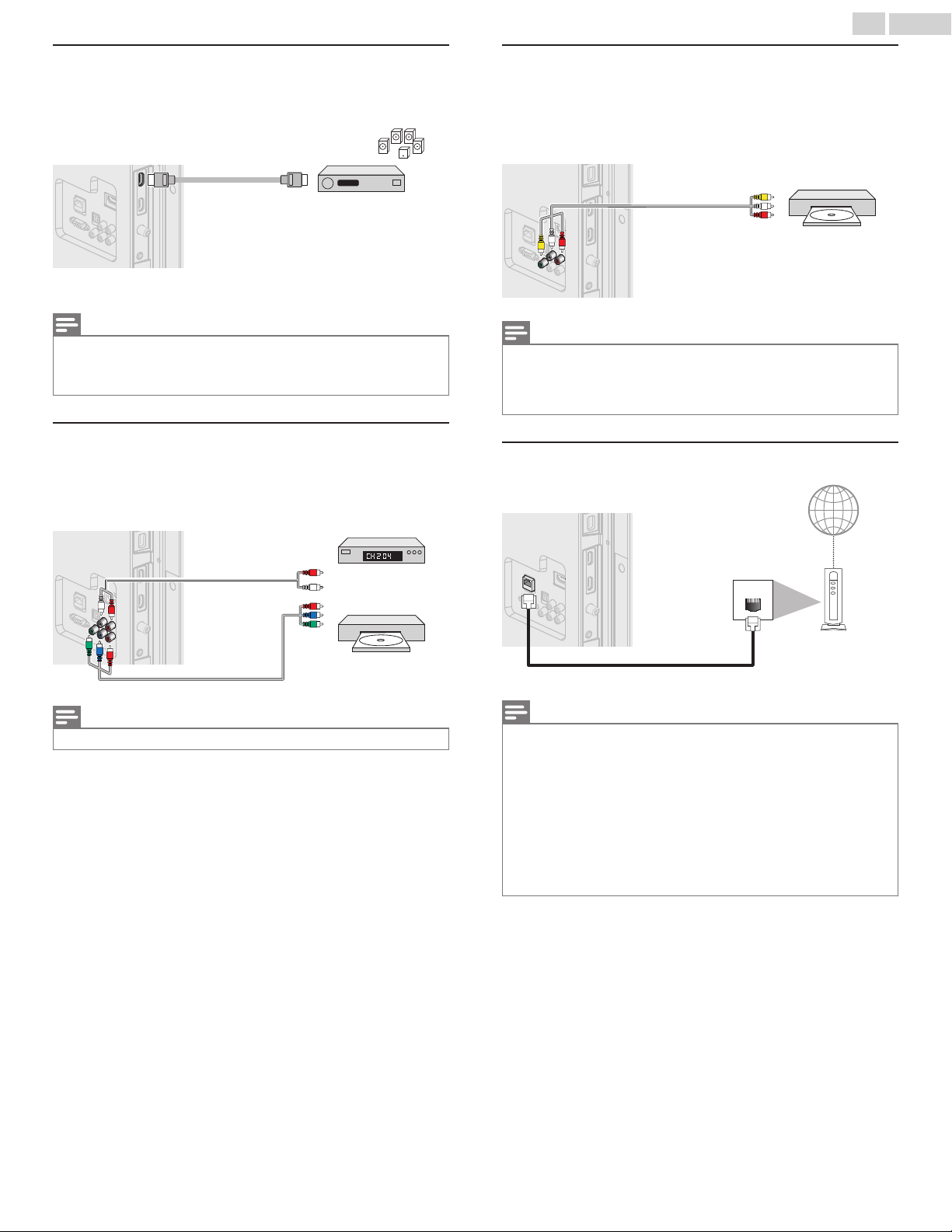
HDMI-ARC Connection
HDMI-ARC allows you to use EasyLink to output TV Audio directly to a
connected Audio device, without the need for an additional Digital Audio
cable.
Note(s)
The HDMI 1 connector is HDMI Audio Return Channel (ARC) compliant. Use it to output Digital
•
Audio to an HDMI home theater system.
Be sure that the device is HDMI CEC and ARC compliant and that the TV is connected to the
•
device using an HDMI cable attached to HDMI-ARC connectors.
Component Analog Video Connection
Component Analog Video Connection offers Better Picture quality for
Video Devices connected to the Unit.
If you connect to the Unit’s Component Video (Y/Pb/Pr) Input jacks,
connect Analog Audio Cables to the Analog Audio (L/R) Input jacks.
Composite Analog Video Connection
Composite Analog Video Connection offers Standard Picture quality for
Video Devices connected to the Unit.
If you connect to the Unit’s Component/Composite Video (Y/VIDEO)
Input jack (green), connect Audio Cables to the Audio (L/R) Input jacks.
When the Audio is monaural, then only connect to the Audio L Input jack.
Note(s)
With this Unit, yellow cable must be connected to Y (green) jack on the Component Video Input
•
jacks.
Whenever you connect to the Composite Video Input jack (Y/VIDEO), you must disconnect the
•
Component Video Input jacks (Pb and Pr). If you leave those jacks connected, it may cause an
unstable picture.
Connecting the TV to the Internet using an Ethernet cable
Note(s)
The Unit accepts 480i, 480p, 720p, 1080i and 1080p of Video signals for this Connection.
•
Note(s)
Please purchase Shielded Ethernet Cables at your local store and use them when you Connect
•
to Network equipment.
•
After connecting an Ethernet Cable, set up necessary Network Settings. Connect to network L
p. 40
Do not insert any cable other than an Ethernet Cable to the Ethernet port to avoid damaging
•
the unit.
If your telecommunications equipment (modem, etc.) does not have Broadband Router
•
functions, connect a Broadband Router.
If your telecommunications equipment (modem, etc.) has Broadband Router functions but
•
there is no vacant port, then add a hub.
For a Rroadband Router, use a Router which supports 10BASE-T / 100BASE-TX.
•
Do not connect your PC directly to the Ethernet port of this unit.
•
Continued on next page.
WLAN
LAN
Network provisioning
equipment
Ethernet cable
Broadband router
Broadband router
Broadband router
Internet
Digital Home
Theater Amplier
OUT
OUT
OUT
IN
IN
IN
Digital Audio
Optical cable
Digital Audio
Optical cable
Digital Audio
Optical cable
PCPCPC
OUT
OUT
OUT
HDMI cable
HDMI cable
HDMI cable
INININ
PCPCPC
OUT
OUT
OUT
HDMI-DVI
conversion cable
HDMI-DVI
conversion cable
HDMI-DVI
conversion cable
IN
IN
IN
OUT
OUT
OUT
Stereo Mini 3.5 mm Plug Audio cable
Stereo Mini 3.5 mm Plug Audio cable
Stereo Mini 3.5 mm Plug Audio cable
IN
IN
IN
VGA cable
VGA cable
VGA cable
IN
IN
IN
PC
PC
PC
OUT
OUT
OUT
Stereo Mini 3.5 mm Plug Audio cable
Stereo Mini 3.5 mm Plug Audio cable
Stereo Mini 3.5 mm Plug Audio cable
IN
IN
IN
17
.English
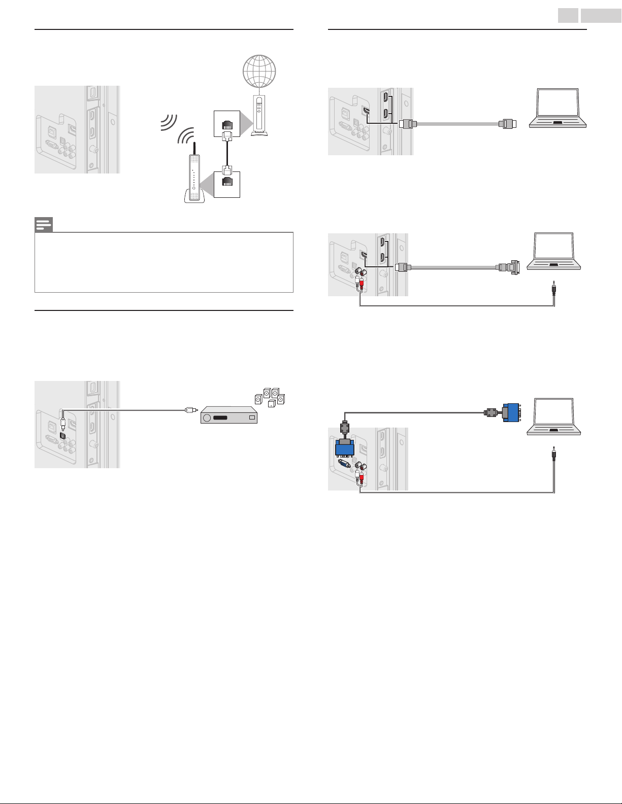
Connecting the TV to the Internet using a Wireless LAN
Note(s)
After you make the wireless connection, set up the necessary network settings. Connect to
•
network L p. 40
Use a Wireless LAN Access Point (AP) (e.g. Broadband Wireless Router) which supports
•
IEEE 802.1 1 b/g/n. (n is recommended for stable operation of the wireless network.)
This unit does not support Ad-hoc mode.
•
Other radio devices or obstacles may cause interference to the wireless network connection.
•
Digital Audio Output Connection
If you connect this Unit to an External Digital Audio Device, you can enjoy
multi-channel Audio like 5.1ch Digital Broadcasting sound.
Use a Digital Audio Optical Cable to connect the Unit to External Digital
Audio Devices.
PC Connection
HDMI Connection
This Unit can be connected to your PC that has an HDMI terminal.
Use an HDMI cable for this Digital Connection.
HDMI-DVI Connection
This Unit can be connected to your PC that has a DVI Terminal.
Use an HDMI-DVI Conversion Cable for this Video Digital Connection and
it requires Stereo mini 3.5mm Plug Audio Cable for Analog Audio signal as
well.
VGA Connection
This unit is equipped with a PC Input jack. If you connect this Unit to your
PC, you can use this Unit as a PC monitor.
Use a VGA cable for this Video Connection and it requires a Stereo mini
3.5mm Plug Audio Cable for Analog Audio signal as well.
Continued on next page.
The following Video signals can be displayed:
Format Resolution Refresh rate
VGA 640 x 480
SVGA 800 x 600
XGA 1,024 x 768
WXGA
1,280 x 768
1,360 x 768
60Hz
FHD 1,920 x 1,080
Other formats or non-standard signals will not be displayed correctly.
Note(s)
Please purchase the VGA cable or HDMI-DVI Conversion Cable that has a ferrite core.
•
The following operations may reduce noise.
•
–Attach a ferrite core to the AC Power Cord of your PC.
–Unplug the AC Power Cord and use the built-in battery of your Portable / Laptop PC.
Use an HDMI cable with the HDMI logo (a certified HDMI cable). High Speed HDMI cable is
•
recommended for the Better compatibility.
The Unit accepts 480i, 480p, 720p, 1080i and 1080p Video signals.
•
HDMI-DVI Connection requires separate Audio Connections as well and the Audio signals are
•
Output as Analog (L/R) Audio.
DVI does not display 480i image which is not in compliance with EIA/CEA-861/861B.
•
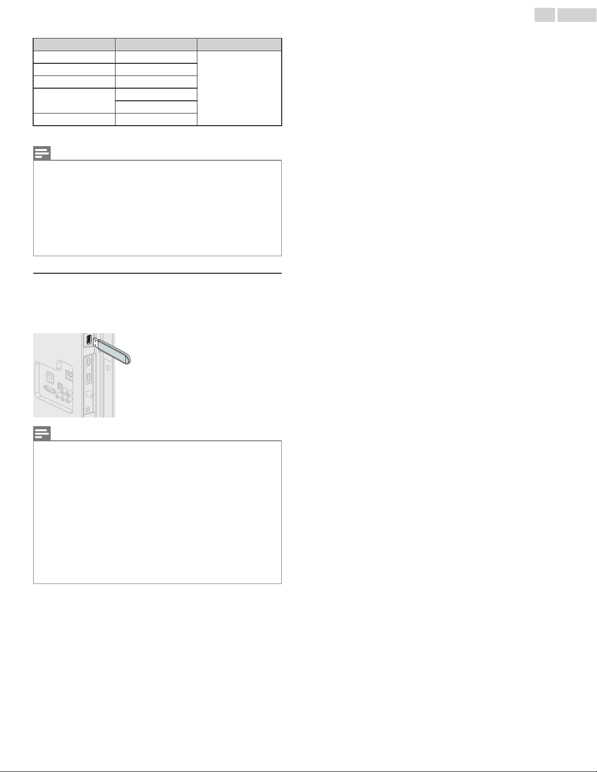
USB Memory Stick
This unit offers easy playback of Picture, Music and Video files.
Insert the USB Memory Stick into the USB terminal shown below.
USB L p. 26
18
.English
Note(s)
The Unit recognizes only a USB Memory Stick.
•
Do Not use a USB hub or an extension cable to connect an External hard disk drive to the Unit.
•
(Not Supported.)
Always insert a USB Memory Stick directly to this Unit.
•
A USB Memory Stick is Not Supplied with this Unit.
•
We Do Not guarantee that All USB Memory Sticks can be supported by this Unit.
•
Be sure to keep a Backup Copy of the Original files on your USB device before you Play them
•
back on this Unit. We have no responsibilities for damage or loss of your USB Stored Data.
To protect your USB Memory Stick files from being erased place the write protect sliding tab in
•
the protect position (if available).
When you are ready to remove a USB Memory Stick, set the Unit to go into Standby mode to
•
avoid any damage to your data and the Unit.
A USB Memory Stick that requires its own driver or the Device with a special system such as
•
fingerprint recognition are Not Supported.
This unit is not allowed to use the USB Memory Stick which requires an External Power Supply
•
(500mA or more).
Continued on next page.
 Loading...