

Page 1

Instruction Manual
9083-2/99
296-12-18 692/002
Betriebsanleitung engl. 06.02
This instruction manual applies to machines from the
following serial numbers onwards:
# 2232224
Page 2

This Instruction Manual is valid for all models and subclasses listed in the
chapter " Specifications ".
The reprinting, copying or translation of PFAFF Instruction Manuals, whether in whole or in
part, is only permitted with our previous authorization and with written reference to the source.
PFAFF Industrie Maschinen AG
Postfach 3020
D-67653 Kaiserslautern
Königstr. 154
D-67655 Kaiserslautern
Editing / Illustrations
Verlag Technische Dokumentation
D-77901 Lahr
Page 3

Contents
Contents ..................................................................................Chapter - Page
1 Safety ............................................................................................................................ 1 - 1
1.01 Directives ...................................................................................................................... 1 - 1
1.02 General notes on safety................................................................................................. 1 - 1
1.03 Safety symbols ............................................................................................................. 1 -2
1.04 Important points for the user.......................................................................................... 1 - 2
1.05 Operating and specialist personnel ................................................................................ 1 - 3
1.05.01 Operating personnel ....................................................................................................... 1 - 3
1.05.02 Specialist personnel ....................................................................................................... 1 - 3
1.06 Danger ........................................................................................................................... 1 - 4
2 Proper use .................................................................................................................... 2 -1
3 Specifications .............................................................................................................. 3 - 1
4 Disposal of machine .................................................................................................... 4 - 1
5 Transport, packaging and storage .............................................................................. 5 - 1
5.01 Transport to the customer’s premises ........................................................................... 5 - 1
5.02 Transport within the customer’s premises..................................................................... 5 - 1
5.03 Disposal of the packaging.............................................................................................. 5 - 1
5.04 Storage .......................................................................................................................... 5 - 1
6 Explanation of the symbols ........................................................................................ 6 - 1
7 Controls........................................................................................................................7- 1
7.01 Main switch ..................................................................................................................7- 1
7.02 Start sewing and interrupt sewing keys ......................................................................... 7 - 1
7.03 Edge trimmer .................................................................................................................7- 2
7.04 Stitch length adjustment wheel ..................................................................................... 7 - 2
7.05 Stitch condensation key ................................................................................................ 7 - 3
8 Mounting and commissioning the machine .............................................................. 8 - 1
8.01 Mounting ....................................................................................................................... 8 - 1
8.01.01 Adjusting the table-top height ........................................................................................ 8 - 1
8.01.02 Mounting the spool holder .............................................................................................. 8 - 2
8.02 Commissioning ............................................................................................................. 8 - 2
8.03 Switching the machine on/off ........................................................................................ 8 - 2
9 Preparation ................................................................................................................... 9 - 1
9.01 Inserting the needle ....................................................................................................... 9 -1
9.02 Winding the bobbin thread, adjusting the thread tension ................................................ 9 - 2
9.03 Removing/Inserting the bobbin case.............................................................................. 9 - 3
9.04 Inserting the bobbin case / Adjusting the bobbin thread tension ..................................... 9 - 3
9.05 Threading the needle thread / Adjusting the needle thread tension ................................. 9 - 4
9.06 Loading the sewing jig ................................................................................................... 9 - 5
9.07 Inserting the sewing jig.................................................................................................. 9 - 6
10 Care and maintenance ................................................................................................10 - 1
10.01 Cleaning the machine ...................................................................................................10 - 1
10.02 Topping up the oil tank..................................................................................................10 - 2
Page 4

Contents
Contents ..................................................................................Chapter - Page
10.03 Checking/adjusting the air pressure ..............................................................................10 - 3
10.04 Cleaning the air filter of the air-filter/lubricator ...............................................................10 - 3
11 Adjustment ..................................................................................................................11 - 1
11.01 Notes on adjustment ....................................................................................................11 - 1
11.02 Tools, gauges and other accessories............................................................................11 - 1
11.03 Abbreviations................................................................................................................11 - 1
11.04 Checking and adjusting aids .........................................................................................11 - 2
11.05 Adjusting the basic machine .....................................................................................11 - 3
11.05.01 Basic position of the machine drive ..............................................................................11 - 3
11.05.02 Preadjusting the needle height ......................................................................................11 - 4
11.05.03 Setting the feed dog at its neutral position ....................................................................11 - 5
11.05.04 Feeding motion of the feed dog ....................................................................................11 - 6
11.05.05 Needle in needle hole center .........................................................................................11 - 7
11.05.06 Hook shaft bearing and backlash ..................................................................................11 - 8
11.05.07 Hook lubrication............................................................................................................11 - 9
11.05.08 Needle rise, hook-to-needle clearance, needle height and bobbin case position finger ..11 - 10
11.05.09 Thread check spring and slack thread regulator ............................................................11 - 11
11.05.10 Bobbin winder ..............................................................................................................11 - 12
11.05.11 Limiting the stitch length ..............................................................................................11 - 13
11.05.12 Presser foot pressure ...................................................................................................11 - 14
11.05.13 Stitch condensation ...................................................................................................... 11 - 15
11.06 Adjusting the edge trimmer ....................................................................................... 11 - 16
11.06.01 Zero position of the knife ..............................................................................................11 - 16
11.06.02 Knife stroke ..................................................................................................................11 - 17
11.06.03 Knife height ..................................................................................................................11 - 18
11.06.04 Knife position in sewing direction..................................................................................11 - 19
11.06.05 Knife position crosswise to sewing direction ................................................................11 - 20
11.07 Adjusting the thread trimmers ...................................................................................11 - 21
11.07.01 Magnet setting .............................................................................................................11 - 21
11.07.02 Lateral alignment of the thread catcher .........................................................................11 - 22
11.07.03 Knife position ................................................................................................................ 11 - 23
11.07.04 Front point of reversal of the thread catcher ..................................................................11 - 24
11.07.05 Manual trimming check ................................................................................................11 - 25
11.07.06 Needle thread tension release .......................................................................................11 - 26
11.07.07 Readjusting the control cam .........................................................................................11 - 27
11.08 Adjusting the automatic presser foot lift .......................................................................11 - 28
11.09 Adjusting the jig drive ................................................................................................11 - 29
11.09.01 Basic setting of the linkage rods................................................................................... 11 - 29
11.09.02 Basic setting of the actuating lever............................................................................... 11 - 30
11.09.03 Distance of the axle of the drive wheel from the bearing axle .......................................11 - 31
11.09.04 Distance of the drive wheel to the centre of the needle ................................................11 - 32
11.09.05 Stitch length adjustment ...............................................................................................11 - 33
11.09.06 Adjusting the air chokes ............................................................................................... 11 - 34
12 Wearing parts .............................................................................................................12 - 1
Page 5

Safety
1 - 1
1 Safety
1.01 Directives
This machine is constructed in accordance with the European regulations contained in the
conformity and manufacturer’s declarations.
In addition to this Instruction Manual, also observe all generally accepted, statutory and other
regulations and legal requirements and all valid environmental protection regulations!
The regionally valid regulations of the social insurance society for occupational accidents or
other supervisory organizations are to be strictly adhered to!
1.02 General notes on safety
● This machine may only be operated by adequately trained operators and only after having
completely read and understood the Instruction Manual!
● All Notes on Safety and Instruction Manuals of the motor manufacturer are to be read
before operating the machine!
● The danger and safety instructions on the machine itself are to be followed!
● This machine may only be used for the purpose for which it is intended and may not be
operated without its safety devices. All safety regulations relevant to its operation are to be
adhered to.
● When exchanging sewing tools (e.g. needle, roller presser, needle plate and bobbin), when
threading the machine, when leaving the machine unattended and during maintenance
work, the machine is to be separated from the power supply by switching off the On/Off
switch or by removing the plug from the mains!
● Everyday maintenance work is only to be carried out by appropriately trained personnel!
● Repairs and special maintenance work may only be carried out by qualified service staff or
appropriately trained personnel!
● Work on electrical equipment may only be carried out by appropriately trained personnel!
● Work is not permitted on parts and equipment which are connected to the power supply!
The only exceptions to this rule are found in the regulations EN 50110.
● Modifications and alterations to the machine may only be carried out under observance of
all the relevant safety regulations!
Page 6
Safety
1 - 2
● Only spare parts which have been approved by us are to be used for repairs! We
expressly point out that any replacement parts or accessories which are not supplied by
us have not been tested and approved by us. The installation and/or use of any such
products can lead to negative changes in the structural characteristics of the machine. We
are not liable for any damage which may be caused by non-original parts.
1.03 Safety symbols
Danger!
Points to be observed.
Danger of injury for operating and specialist personnel!
Caution
Do not operate without finger guard and safety devices.
Before threading, changing bobbin and needle, cleaning
etc. switch off main switch.
1.04 Important points for the user
● This Instruction Manual is an integral part of the machine and must be available to the
operating personnel at all times.
● The Instruction Manual must be read before operating the machine for the first time.
● The operating and specialist personnel is to be instructed as to the safety equipment of the
machine and regarding safe work methods.
● It is the duty of the user to only operate the machine in perfect running order.
● It is the obligation of the user to ensure that none of the safety mechanisms are removed
or deactivated.
● It is the obligation of the user to ensure that only authorized persons operate and work on
the machine.
Further information can be obtained from your PFAFF agent.
I
Page 7

Safety
1 - 3
1.05 Operating and specialist personnel
1.05.01 Operating personnel
Operating personnel are persons responsible for the equipping, operating and cleaning of the
machine as well as for taking care of problems arising in the sewing area.
The operating personnel is required to observe the following points and must:
● always observe the Notes on Safety in the Instruction Manual!
● never use any working methods which could adversely affect the safety of the machine!
● not wear loose-fitting clothing or jewelery such as chains or rings!
● also ensure that only authorized persons have access to the potentially dangerous area
around the machine!
● always immediately report to the person responsible any changes in the machine which
may limit its safety!
1.05.02 Specialist personnel
Specialist personnel are persons with a specialist education in the fields of electrics,
electronics and mechanics. They are responsible for the lubrication, maintenance, repair and
adjustment of the machine.
The specialist personnel is obliged to observe the following points and must:
● always observe the Notes on Safety in the Instruction Manual!
● switch off the On/Off switch before carrying out adjustments or repairs, and ensure that it
cannot be switched on again unintentionally!
● wait until the luminous diode on the control box is no longer blinking or on before beginning
adjustment or repair work.
● never work on parts which are still connected to the power supply! Exceptions are
explained in the regulations EN 50110.
● replace the protective coverings and close the electrical control box afer all repairs or
maintenance work!
Page 8
Safety
1 - 4
74-001
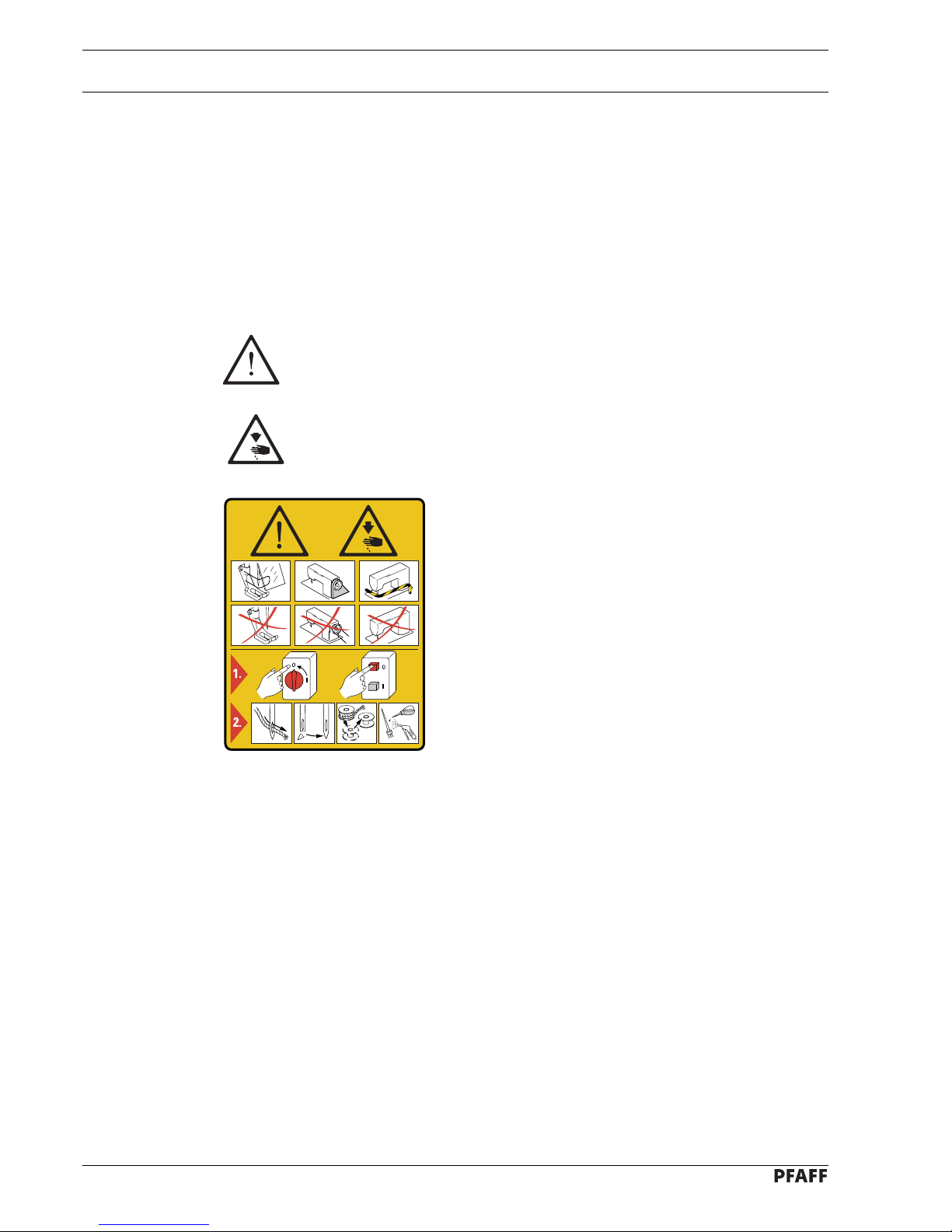
1.06 Danger
A working area of 1 meter is to be kept free both in front of and behind the
machine while it is in operation so that it is always easily accessible.
Never reach into the sewing area while sewing! Danger of injury by the needle!
Never leave objects on the table while adjusting the machine settings! Objects
can become trapped or be slung away! Danger of injury!
Fig. 1 - 01
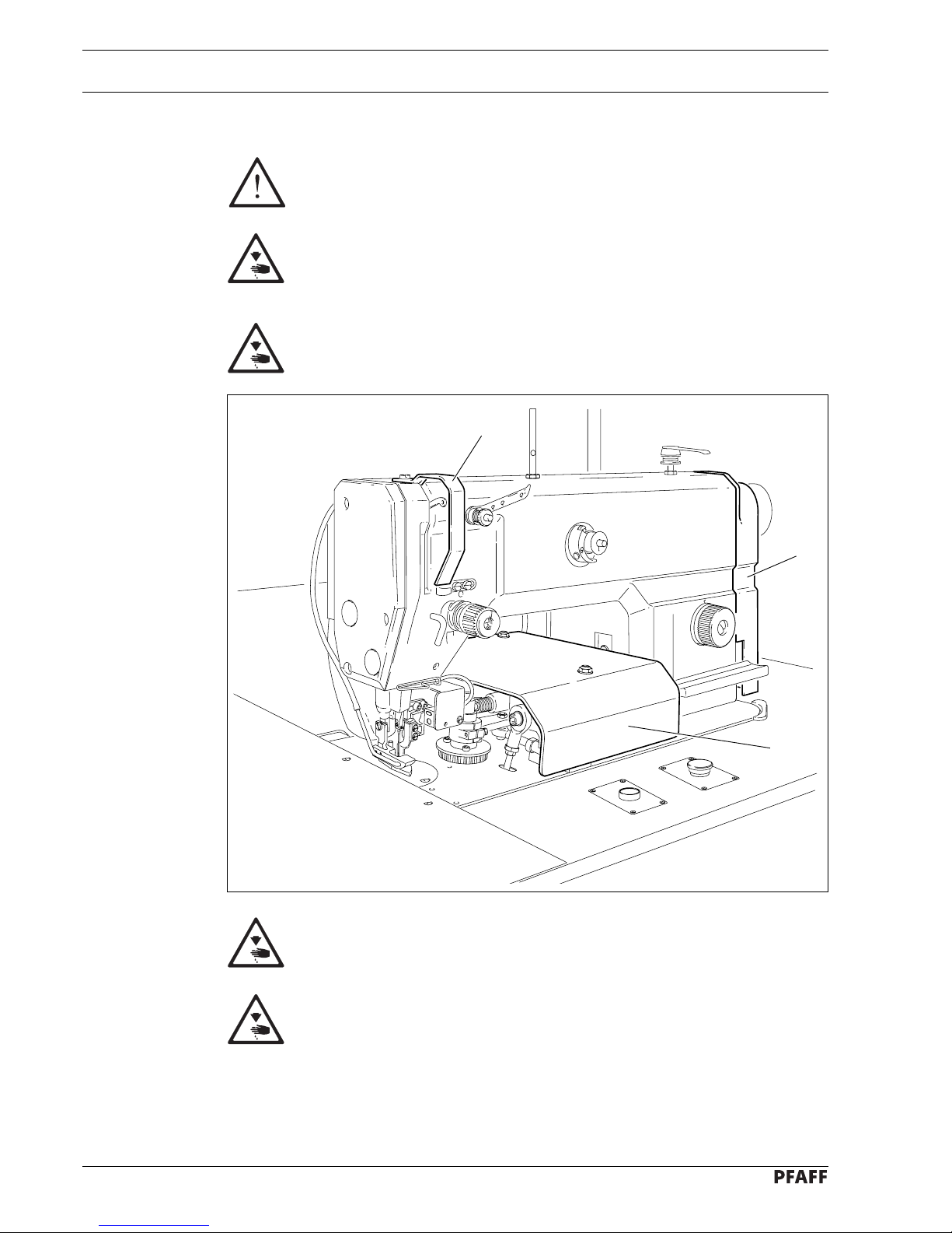
Do not operate the machine without its take-up lever guard 1!
Danger of injury due to the motion of the take-up lever!
Do not operate the machine without covers 2 and 3!
Danger of injury from moving parts!
2
1
3
Page 9

Proper use
2 - 1
2 Proper use
The PFAFF 9083-2/99 is an ultra-high-speed, single-needle lockstitch sewing machine for
stitching and turning small parts.
Any and all uses of this machine which have not been approved of by the
manufacturer are considered to be inappropriate! The manufacturer cannot be
held liable for any damage caused by the inappropriate use of the machine! The
appropriate use of the machine includes the observance of all operational,
adjustment, maintenance and repair measures required by the manufacturer!
Page 10

Specifications
3 - 1
3 Specifications
Stitch type: .................................................................................................. 301 (lockstitch)
Needle system: ........................................................................................................ 134 KK
Needle size in 1/100 mm: ........................................................................................80 - 100
Handwheel eff. dia.: ................................................................................................. 65 mm
Bedplate dimensions: ....................................................................................476 x 177 mm
Machine dimensions:
Length: ..................................................................................................... approx. 1250 mm
Width:......................................................................................................... approx. 800 mm
Height (above table):................................................................................... approx. 300 mm
Max. stitch length:................................................................................................... 4.5 mm
Max. speed: ...................................................................................................... 3500 spm
◆
Connection data:
Operating voltage: ................................................................ 190 - 240 V 50/60 Hz, 1 phase
Max. power consumption: ........................................................................................ 400 VA
Fuse protection: ............................................................................................. 1 x 16 A, inert
Working noise level:
Emission level at workplace at a speed of 2000 spm-1: .............................. LpA < 78 dB(A)
■
(Noise measurement in accordance with DIN 45 635-48-A-1, ISO 11204, ISO 3744, ISO 4871)
Net weight: ................................................................................................... approx. 105 kg
Gross weight: ............................................................................................... approx. 176 kg
▲
Subject to alternation
◆
Dependent on material, work operation and stitch length
■
KpA = 2,5 dB
Page 11

Disposal of machine
4 - 1
4 Disposal of machine
● The proper disposal of the machine is the responsibility of the customer.
● The materials used in the machines are steel, aluminium, brass and various plastics.
The electrical equipment consists of plastics and copper.
● The machine is to be disposed of in accordance with the locally valid environmental
protection regulations. If necessary, a specialist is to be commissioned.
Special care is to be taken that parts soiled with lubricants are separately
disposed of in accordance with the locally valid pollution control regulations!
Page 12

Transport, packaging and storage
5 - 1
5 Transport, packaging and storage
5.01 Transport to the customer’s premises
Within Germany, machines with a table are delivered without packaging. Machines without a
table (sewing head only) and machines which are to be exported are packaged.
5.02 Transport within the customer’s premises
The manufacturer bears no liability for transport within the customer’s premises or to the
individual locations of use. Make sure that the machines are always transported upright.
5.03 Disposal of the packaging
The packaging of these machines consists of paper, cardboard and VCE fiber. The proper
disposal of the packaging is the responsibility of the customer.
5.04 Storage
The machine can be stored for up to 6 months if not in use. During this time it should be
protected from dust and moisture.
For longer storage the individual parts of the machine, especially the moving parts, must be
protected from corrosion, e.g. by a film of oil.
Page 13

Explanation of the symbols
6 - 1
6 Explanation of the symbols
In the following section of this Instruction Manual, certain tasks or important pieces of
information are accentuated by symbols.
The symbols used have the following meanings:
Note, information
Cleaning, care
Lubrication, greasing
Servicing, repairing, adjustment, maintenance
(only to be carried out by specialist personnel)
Page 14
Controls
7 - 1
74-003
74
-
002
Fig. 7 - 01
7 Controls
7.01 Main switch
● Turn the machine on/off by pressing the
main switch 1.
7.02 Start sewing and interrupt sewing keys
● Press key 1 to start the sewing function.
● To interrupt the sewing function, press
key 2. When it is pressed down, key 2
locks: To release it, it must be turned to
the right.
When the thread breaks, the
sewing function can be
interrupted with key 2.
However, do not remove the
workpiece from the jig! After the
thread has been repaired, the
sewing function can be
continued by releasing key 2
and pressing key 1.
Fig. 7 - 02
1
2
1
Page 15
Controls
7 - 2
74-005
74-004
7.03 Edge trimmer
Do not touch the moving knife!
Danger of injury!
● The automatic operation of the edge
trimmer is switched on or off with
switch 1.
● Switch 2 is used to select the time for
switching on the knife.
Top position: The knife is switched
on immediately.
Bottom position: The knife is switched
on with a delay. The
time delay is set with
potentiometer 3.
Fig. 7 - 03
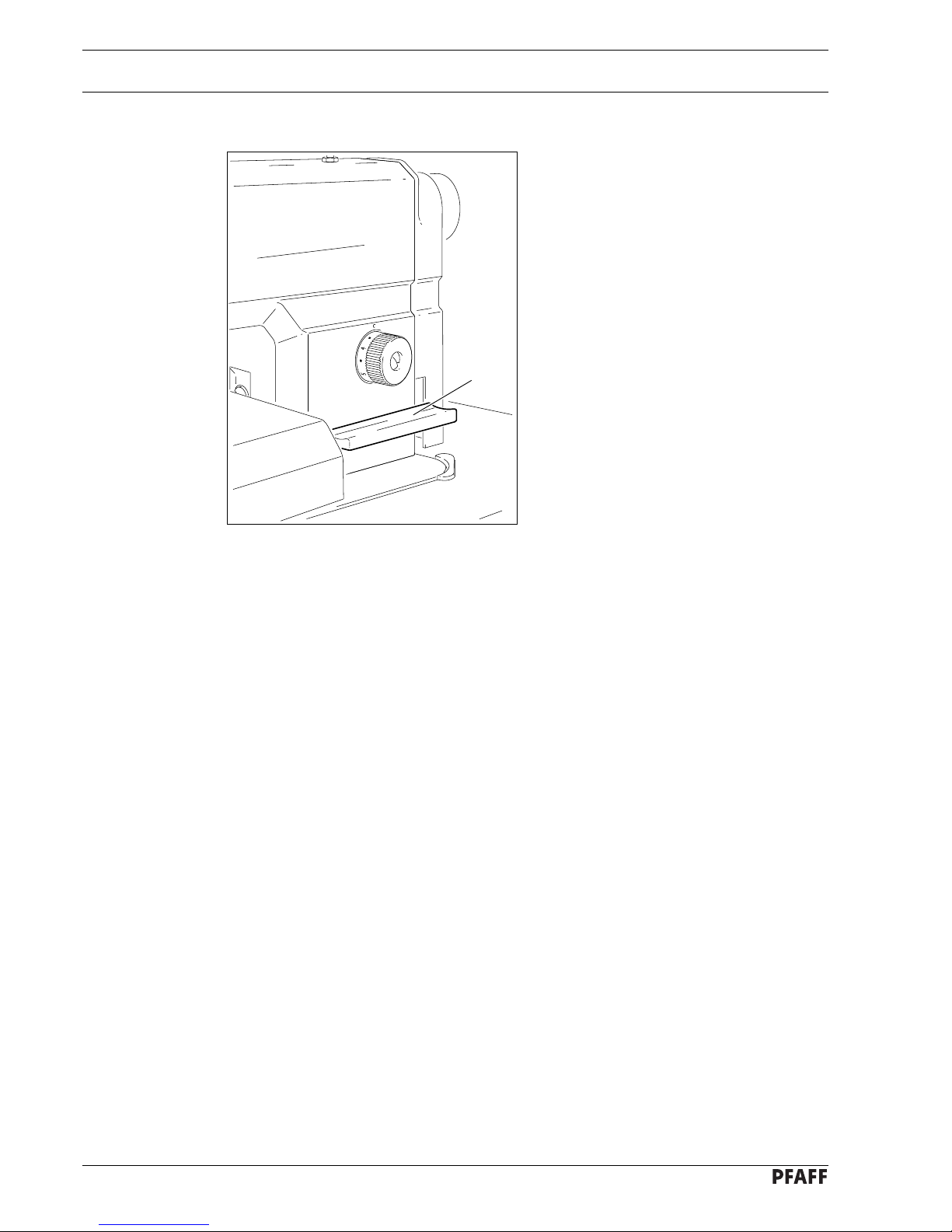
7.04 Stitch length adjustment wheel
● To set the required stitch length, press
and simultaneously turn adjustment
wheel 1.
Fig. 7 - 04
1
2
3
1
Page 16
Controls
7 - 3
74-041
7.05 Stitch condensation key
● While key 1 is pressed, the stitch length
is condensed to 1 mm.
Fig. 7 - 05
1
Page 17
Mounting and commisioning the machine
8 - 1
74-006
8 Mounting and commissioning the machine
The machine must only be mounted and commissioned by qualified personnel!
All relevant safety regulations are to be observed!
8.01 Mounting
The necessary electricity supply must be available at the machine’s location. Also, a stable
and horizontal surface as well as adequate lighting are required at the location.
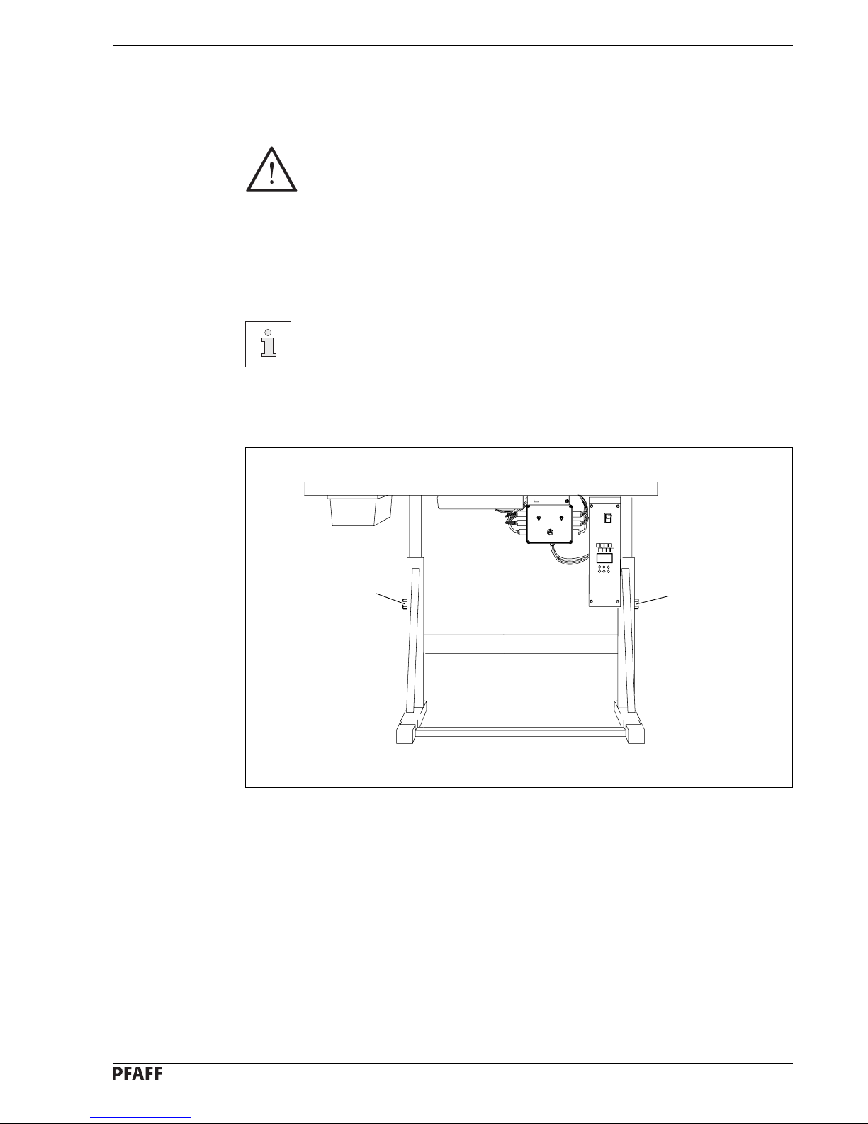
Depending on the type of table, the method of packaging used may require that
the table top be lowered for transport. The following is a description of how to
adjust the height of the table top.
8.01.01 Adjusting the table-top height
● Loosen screws 1 and set the table height as required.
● Well tighten screws 1.
Fig. 8 - 01
1
1
Page 18
Mounting and commisioning the machine
8 - 2
8.02 Commissioning
● Examine the machine, in particular the electric cables, for any damage.
● Before commissioning the machine, clean it thoroughly, also see Chapter 10 Care and
Maintenance!
● Connect the machine to the compressed air system. The manometer should display a
pressure of 6 bar. If necessary, set this value, see Chapter 10.03 Checking / adjusting
the air pressure.
Have qualified personnel check whether the machine can be operated with the
available voltage and whether it is connected properly. If there are any
irregularities do not operate the machine!
The machine may only be connected to an earthed socket!
8.03 Switching the machine on/off
● Switch the machine on or off in accordance with Chapter 7.01 Main switch.
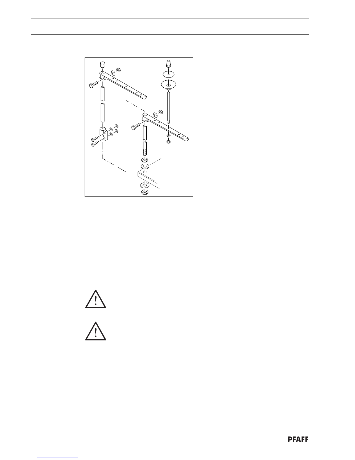
8.01.02 Mounting the spool holder
● Mount the spool holder as shown in
Fig. 8-02.
● Insert the spool holder into the hole in the
table top and fasten it with the nuts
enclosed.
Fig. 8 - 02
Page 19
Preparation
9 - 1
74-007
9 Preparation
All regulations and instructions in this Instruction Manual are to be observed!
Special attention is to be paid to the safety regulations!
All preparation work is only to be carried out by appropriately trained personnel.
Before all preparation work, the machine is to be separated from the electricity
supply by removing the plug from the mains or switching off the On/Off switch!
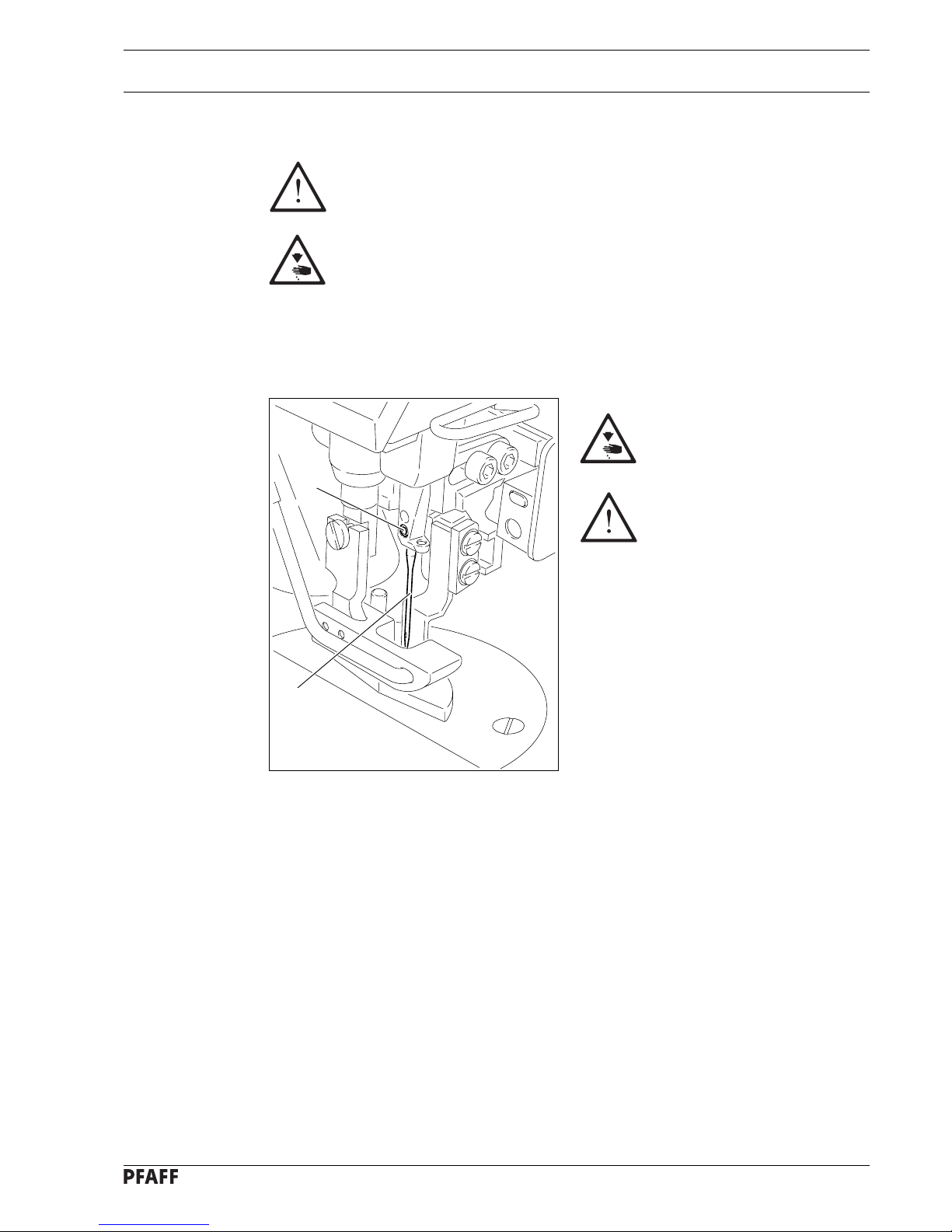
9.01 Inserting the needle
Switch off the machine!
Danger of injury due to
unintentional starting of the
machine!
Only use needles of
system 134 KK.
● Raise needle bar.
● Loosen screw 1 and insert needle 3 until
you feel it stop.
● Tighten screw 1.
Fig. 9 - 01
1
2
Page 20

Preparation
9 - 2
Fig. 9 - 02
● Place an empty bobbin 1 onto bobbin shaft 2.
● Thread the bobbin in accordance with Fig. 9-02 and wind it anti-clockwise around bobbin 1
a few times.
● Switch on the bobbin winder while at the same time pressing bobbin winder spindle 2 and
lever 3.
The bobbin fills up during sewing.
If the machine is only being used to wind the bobbin (without sewing), a bobbin
case must be inserted in the hook! (Danger of damage to the hook).
● The tension of the thread on bobbin 1 can be adjusted with knurled screw 4.
● The bobbin winder stops automatically when bobbin 1 is full.
If the thread is wound unevenly:
● Loosen nut 5.
● Turn thread guide 6 accordingly.
● Tighten nut 5.
6
5
4
9.02 Winding the bobbin thread, adjusting the thread tension
-
3
2
1
+
Page 21
Preparation
9 - 3
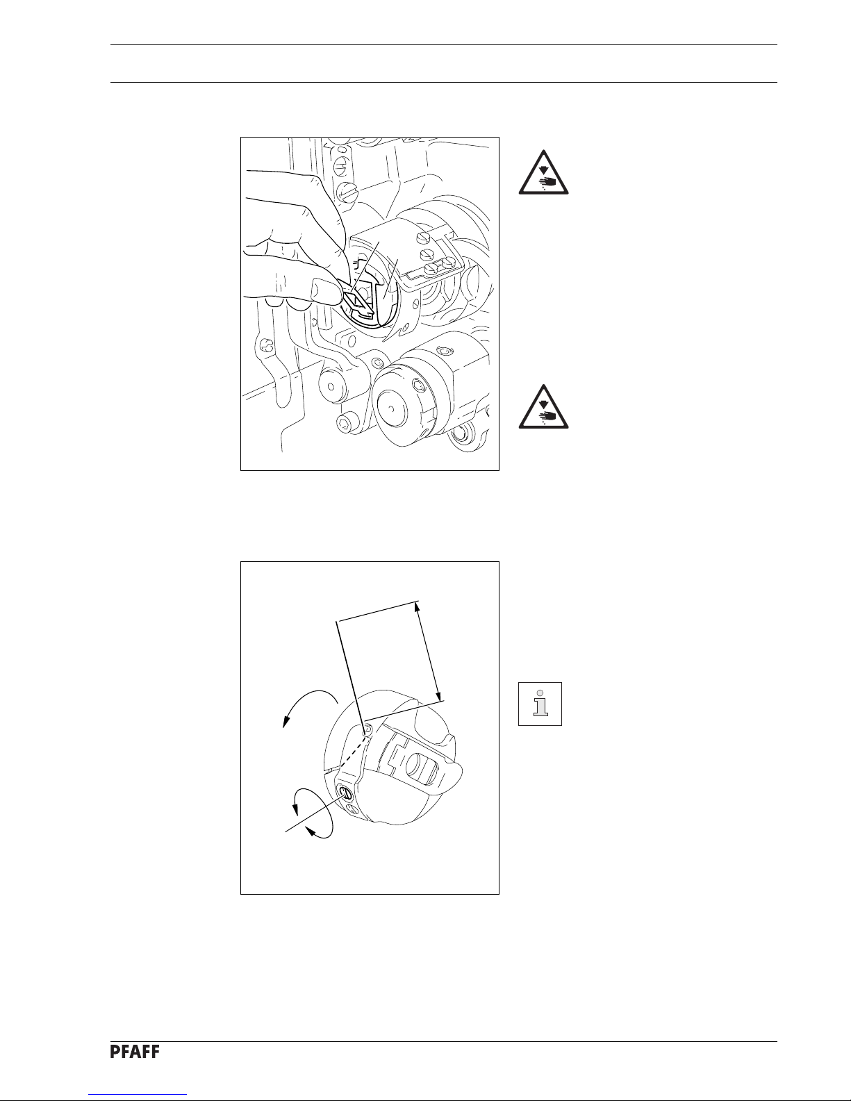
Fig. 9 - 03
9.04 Inserting the bobbin case / Adjusting the bobbin thread tension
● Insert the bobbin into the bobbin case.
● Pass the thread through the slot under the
spring according to Fig. 9-04.
● Adjust the thread tension by turning
screw 1.
When the thread is pulled, the
bobbin must rotate in the
direction of the arrow.
Fig. 9 - 04
5 cm
1
+
-
9.03 Removing/Inserting the bobbin case
Switch off the machine!
Danger of injury due to
unintentional starting of the
machine!
Removing the bobbin case:
● Tilt back the machine.
● Raise latch 1 and remove bobbin case 2.
Inserting the bobbin case:
● Press bobbin case 2 until you feel it snap
into the bobbin case base.
Return the machine to its
upright position using both
hands!
Danger of injury by crushing
between the machine and the
table top!
2
1
Page 22

Preparation
9 - 4
74-008
9.05 Threading the needle thread / Adjusting the needle thread tension
Fig. 9 - 05
Switch off the machine!
Danger of injury due to unintentional starting of the machine!
● Thread the machine as shown in Fig. 9-05.
● Adjust the needle thread tension by turning disk 1.
1
-
+
Page 23

Preparation
9 - 5
9.06 Loading the sewing jig
Fig. 9 - 06
● Insert the lining between cloth plate 1 and material clamp 2 so that it is touching guide
pins 3.
● Close the material clamp 2.
● Place the preliminary cut workpiece for the fullness on material clamp 2 and close material
clamp 4.
74-009
1
3
3
2
4
Page 24

Preparation
9 - 6
9.07 Inserting the sewing jig
● Move sewing jig 1 against stop 2.
● The machine is ready for operation.
74-010
1
2
Fig. 9 - 07
Page 25

Care and maintenance
10 - 1
10 Care and maintenance
Cleaning .............................................................. daily, several times if in continuous use
Checking the oil level ................................................................................... once a year
▲
Checking / adjusting the air pressure ........................................................daily, before use
Cleaning the air filter of the air filter/lubricator ................................................... as required
▲
These maintenance intervals are calculated for the average running time of a
single shift operation. If the machine is operated more than this, shorter
intervals are recommended.
10.01 Cleaning the machine
Switch off the machine!
Danger of injury due to
unintentional starting of the
machine!
● Tilt back the machine.
● Clean the hook and hook compartment
daily, more often if in continuous
operation.
Return the machine to its
upright position using both
hands!
Danger of injury by crushing
between the edge of the
machine and the table top!
Fig. 10 - 01
Page 26

Care and maintenance
10 - 2
74-011
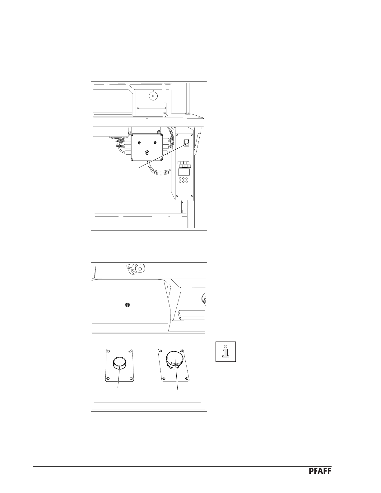
10.02 Topping up the oil tank
The oil reservoir must always
have oil in it.
● Whenever it is necessary to refill the
reservoir, tilt back the machine and let it
rest on the sewing head support.
● Fill oil through hole 1 into the reservoir 2
up to the level of the front edge (see
arrow).
Return the machine to its
upright position using both
hands!
Danger of injury by crushing
between the machine and the
table top!
Only use oil with a mean viscosity of 10.0 mm2/s at 40°C and a density
of 0.847 g/cm3 at 15°C.
We recommend PFAFF sewing machine oil, part no. 280-1-120 105.
Fig. 10 - 02
2
1
Page 27

Care and maintenance
10 - 3
10
12
0
6
4
2
8
16
14
100
50
150
0
200
230
10
12
0
6
4
2
8
16
14
100
50
150
0
200
230
Fig. 10 - 03
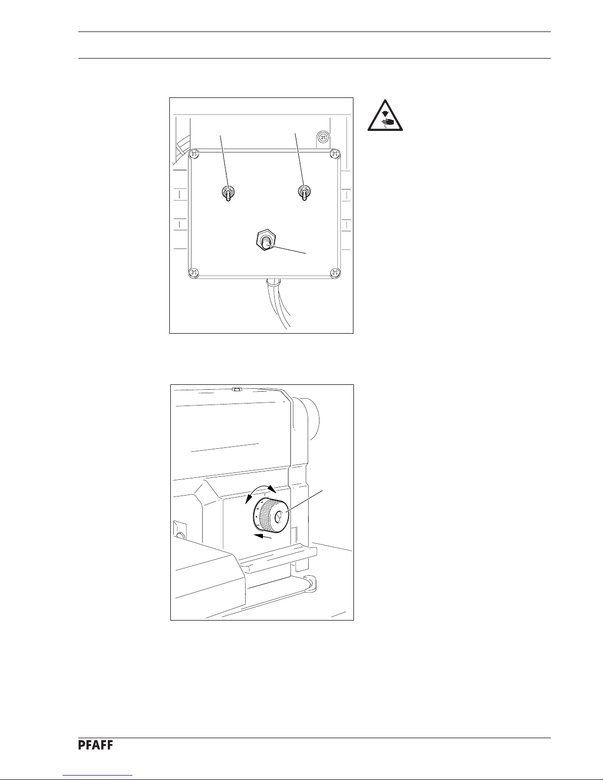
10.04 Cleaning the air filter of the air-filter/lubricator
Switch the machine off!
Disconnect the air hose at the
air-filter/lubricator.
To drain water bowl 1:
● Water bowl 1 drains itself automatically
whe the compressed-air hose is disconnected from the air-filter/lubricator.
Cleaning filter 2:
● Unscrew water bowl 1.
● Take out filter 2.
● Clean filter 2 with compressed air or iso-
propyl alcohol (part No. 95-665 735-91).
● Screw in filter 2 and screw on water
bowl 1.
Fig. 10 - 04
2
1
1
2
10.03 Checking/adjusting the air pressure
● Before operating the machine, always
check the air pressure on gauge1.
● Gauge 1 must show a pressure of 6 bar.
● If necessary adjust to this reading.
● To do so, pull knob 2 upwards and turn it
so that the gauge shows a pressure of 6
bar.
Page 28

Adjustment
11 - 1
11 Adjustment
On the PFAFF 9083-2/99 no adjustable clamp must be fastened to the needle
bar! This could cause damage to the special coating of the needle bar.
11.01 Notes on adjustment
All following adjustments are based on a fully assembled machine and may only be carried
out by expert staff trained for this purpose.
Machine covers, which have to be removed and replaced to carry out checks and
adjustments, are not mentioned in the text.
The order of the following chapters corresponds to the most logical work sequence for
machines which have to be completely adjusted. If only specific individual work steps are
carried out, both the preceding and following chapters must be observed.
Screws, nuts indicated in brackets ( ) are fastenings for machine parts, which must be
loosened before adjustment and tightened again afterwards.
11.02 Tools, gauges and other accessories
● 1 set of screwdrivers with blade widths from 2 to 10 mm
● 1 set of wrenches with jaw widths from 7 to 14 mm
● 1 set of Allan keys from 1.5 to 6 mm
● 1 metal ruler, part no. 08-880 218-00
● 1 locking pin (5 mm diameter), part no. 13-033 346-05
● 1 adjustment gauge, part no. 61-111 639-70
● Threads and test materials
11.03 Abbreviations
t.d.c. = top dead centre
b.d.c. = bottom dead centre
Page 29

Adjustment
11 - 2
11.04 Checking and adjusting aids
With the aid of blocking pin 1 (part No. 13-033346-05) and if necessary
adjustment gauge 3 (part No. 61-111 639-70) the machine can be blocked in the
following positions for adjustment
Needle bar position 1.8 mm past b.d.c.
● Turn balance wheel until needle bar is roughly in required position
● Insert blocking pin 1 in hole
● Turn balance wheel slightly back and forth until blocking pin engages crank 2
Needle bar position 0.6 mm past t.d.c.
● Set needle bar roughly at required position
● Place adjustment gauge 3 onto pins 4 and 5, making sure right side is used (for 30 or 36
mm needle bar stroke)
Needle bar position 0.6 mm past b.d.c.
● Set needle bar roughly at required position
● Place adjustment gauge 3 onto pins 4 and 5, making sure right side is used (for 30 or 36
mm needle bar stroke)
Fig. 11 - 01
1
2
4
5
3
Page 30

Adjustment
11 - 3
11.05 Adjusting the basic machine
11.05.01 Basic position of the machine drive
This adjustment is only required if toothed belt 2 has been removed.
Requirement
When the needle bar position is 0.6 mm above the BDC, the marks on the machine housing
3 and toothed belt wheel 1 must be flush with each other.
Fig. 11 - 02
● Set needle bar at 0.6 mm past b.d.c.
● Turn toothed belt sprocket 1 according to Requirement and push on toothed belt 2.
Beim Einbau des Motors auf die richtige Lage von Wellenflansch, Ruckdämpfer
und Motorflansch achten!
57-42a
3
4
1
2
Page 31

Adjustment
11 - 4
11.05.02 Preadjusting the needle height
Requirement
When the needle bar is positioned 1.8 mm above BDC, the mark on the needle bar 1 must
be flush with the bottom edge of the needle bar frame 3.
Fig. 11 - 03
● Set needle bar at 1.8 mm past b.d.c. and block machine with blocking pin, see
Chapter 11.04 Checking and adjusting aids.
● Move needle bar 1 (screw 2), without turning it, according to the requirement.
2
1
3
Page 32

Adjustment
11 - 5
74-012
11.05.03 Setting the feed dog at its neutral position
Requirement
With the stitch length set at “0, cranks 1 and 3 should be in alignment, and there should be
no feeding motion of the feed dog when the balance wheel is turned.
Fig. 11 - 04
3
2
1
● Cancel the stitch condensation limit, see Chapter 11.05.13 Stitch condensation.
● Raise the presser foot and set the stitch length at “0”.
● Adjust crank 1 (screw 2) in accordance with the requirement.
● Set the stitch condensation limit as described in Chapter 11.05.13 Stitch condensation.
Page 33

Adjustment
11 - 6
74-049
11.05.04 Feeding motion of the feed dog
Requirement
When the needle bar is positioned at 0.6 after t.d.c., and with the longest stitch length set,
lever 4 should not move, when the stitch condensation key 3 is operated.
1
2
Fig. 11 - 05
● Without moving it sideways, adjust eccentric 1 (slightly loosen screws 2) in accordance
with the requirement.
4
74-014
3
Page 34

Adjustment
11 - 7
11.05.05 Needle in needle hole center
Requirement
The needle must penetrate the needle hole exactly in the middle.
● Set the needle in the needle hole.
● Loosen screws 1, 2 and 3.
● Move the needle bar frame 4 according to the requirement.
● Tighten screw 2 and turn screw 3 slightly.
● Via screw 1, bring the retracted guide bolt to the eye of the needle bar frame 4 and tighten
it.
● Turn the handwheel a few times to prevent distortion to the needle bar frame 4.
● Tighten screw 3.
74-015
3
2
1
4
Fig. 11 - 06
Page 35

Adjustment
11 - 8
74
-
016
11.05.06 Hook shaft bearing and backlash
Requirement
1. The front edge of the hook shaft 6 must be at a distance of 14.5 mm to the needle
center. At the same time, the slot in the hook shaft bearing 1 (see arrow) must be parallel to the bedplate and pointing opposite to the direction of sewing.
2. There must be a slight amount of play between the gears 3 and 5.
4
3
1
5
Fig. 11 - 07
● Align hook shaft bearing 1 (screw 2) according to requirement 1.
● Slide gear 3 (screws 4) on to the shaft according to requirement 2.
1
14,5 mm
6
2
Page 36

Adjustment
11 - 9
11.05.07 Hook lubrication
Requirement
1. The centrifugal disk 1 must be positioned 1.5 mm in front of the oil ring 3.
2. When the machine is running at full speed, after approx. 10 seconds a mark should be
made by a fine stripe of oil on the strip of paper placed over the needle plate cutout.
The adjustment is only necessary if the wick has been replaced.
When replacing the wick, make sure that the new wick is impregnated with oil.
● Move the centrifugal disk 1 (screw 2) according to requirement 1.
● Check requirement 2. If necessary, move centrifugal disk 1.
Fig. 11 - 08
2
1
3
1,5 mm
Page 37

Adjustment
11 - 10
11.05.08 Needle rise, hook-to-needle clearance, needle height and bobbin case
position finger
Requirement
With the needle at 1.8 mm after BDC,
1. the hook point 6 must point to the middle of the needle and be at a distance of
0.05 mm - 0.1 mm to the clearance cut of the needle, and
2. the top edge of the needle eye must be 0.8 mm below the hook point.
3. Between the projection of the bobbin case position finger 4 and the bottom of the
retaining groove there should be a distance of 0.5 mm.
● Using the adjustment pin, position the needle bar at 1.8 mm after BDC.
● Adjust the hook according to requirement 1.
● Tighten screw 1.
● Move needle bar 2 (screw 3) without turning it according to requirement 2.
● Align bobbin case position finger 4 (screw 5) according to requirement 3.
Fig. 11 - 09
0,05 - 0,1 mm
6
1
0,5 mm
4
5
4
2
3
0,8 mm
Page 38

Adjustment
11 - 11
4
3
-
1
2
+
● Turn thread tension 1 (screw 2) according to requirement 1.
● Turn thread tension 3 (screw 4) according to requirement 2.
Due to technical sewing reasons it may be necessary to deviate from the spring
stroke indicated above.
Move the slack thread regulator 3 (screw 4) toward the "+" (= more thread) or
toward the "-" (= less thread)
Fig. 11 - 10
7 mm
11.05.09 Thread check spring and slack thread regulator
Requirement
1. The motion of the thread check spring must be completed when the needle point enters
the material (spring stroke approx. 7 mm).
2. When the thread loop is at its largest when going around the hook, the thread check
spring must have moved by approx. 1 mm.
Page 39

Adjustment
11 - 12
Fig. 11 - 11
1
2
5
4
3
11.05.10 Bobbin winder
Requirement
1. With the bobbin winder on, the drive wheel 1 must engage reliably.
2. With the bobbin winder off, the friction wheel 5 must not be driven by the drive
wheel 1.
3. The bobbin winder must turn off automatically when the thread level is approx. 1 mm
from the edge of the bobbin.
● Move drive wheel 1 (screws 2) in accordance with requirement 1 and 2.
● Move bolt 3 (screw 4) in accordance with requirement 3.
Page 40

Adjustment
11 - 13
11.05.11 Limiting the stitch length
The maximum stitch length which can be selected can be limited mechanically.
2
4
3
The setting for the maximum stitch length should not be larger than 4.5 mm!
● Set the desired maximum stitch length with regulator disk 1.
● Move crank 2 (screws 3) down against stop 4.
Fig. 11 - 12
1
Page 41

Adjustment
11 - 14
Fig. 11 - 13
1
-
+
11.05.12 Presser foot pressure
Requirement
The material must be fed reliably. In the process, pressure marks on the material must not
be made.
● Turn screw 1 in accordance with the requirement.
Page 42

Adjustment
11 - 15
74-026
Fig. 11 - 14
11.05.13 Stitch condensation
Requirement
When the stitch length is set at “1”, screw 2 should be touching lever 4.
● Select stitch length “1” with adjustment wheel 1.
● Adjust screw 2 (nut 3) in accordance with the requirement.
2
3
4
1
Page 43

Adjustment
11 - 16
74-018
74-045
11.06 Adjusting the edge trimmer
11.06.01 Zero position of the knife
Requirement
When the edge trimmer is switched off
1. Pawl 5 should lock into place and
2. The knife should not move when the balance wheel is turned.
Fig. 11 - 15
● Adjust plunger 1 (nuts 2) in accordance with requirement 1.
● Adjust slotted lever 3 (screw 4) in accordance with requirement 2.
4
3
1
2
5
Page 44

Adjustment
11 - 17
11.06.02 Knife stroke
Requirement
When the edge trimmer is switched on, and the needle bar is positioned at it b.d.c., the
knife should be at the top of its stroke.
Fig. 11 - 16
● Adjust eccentric 1 (two screws 2) in accordance with the requirement.
74-019
1
2
Page 45

Adjustment
11 - 18
74-044
11.06.03 Knife height
Requirement
When knife 1 is at its b.d.c., the front edge of the knife blade should be approx. 0.5 mm
below the top edge of the stationary knife.
Fig. 11 - 17
● Adjust knife 1 (screws 2) in accordance with the requirement.
74-020
0,5 mm
74-021
1
2
Page 46

Adjustment
11 - 19
74-044
11.06.04 Knife position in sewing direction
Requirement
When the needle is at its b.d.c., the centre of the knife blade should be positioned at "needle
centre".
Fig. 11 - 18
● Adjust knife bracket 1 (screw 2) according to the requirement.
74-022
74-023
1
2
Page 47

Adjustment
11 - 20
74-044
11.06.05 Knife position crosswise to sewing direction
Requirement
The knife should be resting on the stationary knife with light pressure.
Fig. 11 - 19
● Adjust knife bracket 1 (screw 2) according to the requirement.
74-024
2
1
Page 48

Adjustment
11 - 21
Fig. 11 - 20
1
96 mm
4
3
5
4
2
6
0,1 mm
8
7
11.07 Adjusting the thread trimmers
11.07.01 Magnet setting
Requirement
1. The distance between the bottom edge of the plunger and the top edge of the
washer 5 must be 96 mm.
2. When the thread trimmer is in resting position (magnet retracted), the roller lever 6 must
rest against bolt 7 and be at a distance of approx. 0.1 mm from roller 8.
● Turn plunger 1 (nut 2) according to requirement 1.
● Bring thread trimmer into resting position.
● Move magnet holder 3 (screws 4) according to requirement 2.
Page 49

Adjustment
11 - 22
11.07.02 Lateral alignment of the thread catcher
Requirement
1. The tip of the thread catcher 5 must point exactly to the center of the needle.
2. The thread catcher 5 must be horizontal. It must not graze anything when it is operating.
● Remove knife 1 (screw 2).
● Move needle bar to its BDC.
● Loosen stop 3 (screws 4).
● Position thread catcher 5 (screw 6) manually in front of the needle.
● Align thread catcher 5 (screws 7) according to the requirements.
For further adjustments, leave knife 1 removed and stop 3 loosened.
Fig. 11 - 21
7
5
4
3
1
2
5
6
Page 50

Adjustment
11 - 23
Fig. 11 - 22
4 mm
1
1
2
3
11.07.03 Knife position
Requirement
1. There must be a distance of 4 mm between the cutting edge of the knife and the needle.
2. The right edge of the knife 1 must not extend beyond the right edge of the thread catcher
(see arrow).
● Bring the needle bar to BDC.
● Slide knife 1 under the locking tab and align according to requirement 1.
● Tighten screw 2 lightly.
● Adjust thread catcher carrier 3 by hand until the wedge point in the thread catcher is
positioned just in front of the cutting edge of the knife.
● Align knife 1 according to requirement 2 and tighten screw 2.
Page 51

Adjustment
11 - 24
11.07.04 Front point of reversal of the thread catcher
Requirement
When the thread catcher 5 is at its front point of reversal, the rear edge of the thread catcher
cutout must be positioned 1 mm before the bobbin case position finger 6.
3
4
2
1
Fig. 11 - 23
6
5
1 mm
● Swing roller level 1 into the lowest point of the control cam 2.
● Move thread catcher carrier 3 (screw 4) according to the requirement.
Page 52

Adjustment
11 - 25
2
1
5
4
3
1
Fig. 11 - 24
11.07.05 Manual trimming check
Requirement
Two threads must be cut perfectly both left and right in the cutout of thread catcher 1.
● Move thread catcher 1 by hand to its front point of reversal.
● Double the thread and insert into catcher cutout.
● Carry out trimming operation manually.
● If the threads are not cut according to the requirement, align thread catcher 1
(screws 2) with knife 3 accordingly.
● Move stop 4 against thread catcher 1 and tighten screws 5.
● Check chapter 11.07.02 Lateral alignment of the thread catcher, and readjust if
necessary.
Page 53

Adjustment
11 - 26
11.07.06 Needle thread tension release
Requirement
When magnets 3 are attracted, there should be a distance between the tensions disks 4 of
at least 0.5 mm.
Fig. 11 - 25
● Adjust screw 1 (nut 2) in accordance with the requirement.
0,5 mm
4
1
2
3
Page 54

Adjustment
11 - 27
2
3
4
1
Fig. 11 - 26
11.07.07 Readjusting the control cam
Requirement
When the take-up lever is at TDC, the roller lever 1 must be brought from the highest point
of the control cam 2 and moved against bolt 4 (basic position).
● Switch on machine and sew a few stitches.
● Trigger cutting operation.
● Check to see if the thread was cut cleanly and roller level 1 is in basic position.
● If necessary, turn control cam 2 (screws 3) according to the requirement.
Page 55

Adjustment
11 - 28
11.08 Adjusting the automatic presser foot lift
Requirement
When the automatic presser foot lift is operated, there should be a clearance of 9 mm
between the presser foot and the top of the needle plate.
● Adjust solenoid 1 (screw 2) in accordance with the requirement.
Fig. 11 - 27
2
1
74-025
9 mm
Page 56

Adjustment
11 - 29
Fig. 11 - 28
11.09 Adjusting the jig drive
11.09.01 Basic setting of the linkage rods
Requirement
1. The spherical heads 1 of linkage rod 5 should be at a distance of 100 mm from each
other (centre hole to centre hole).
2. The spherical heads 3 of linkage rod 6 should be at a distance of 75 mm from each other
(centre hole to centre hole).
● Adjust the spherical heads 1 (nuts 2) in accordance with requirement 1.
● Adjust the spherical heads 3 (nuts 4) in accordance with requirement 2.
74-030
5
6
3
3
1
1
2
2
4
75 mm
100 mm
Page 57

Adjustment
11 - 30
11.09.02 Basic setting of the actuating lever
Requirement
1. The spherical head 1 should be positioned in the centre of the elongated hole of actuating
lever 5.
2. When the needle is positioned 0.8 mm after t.d.c., the actuating lever 5 should be hori-
zontal.
● Adjust the spherical head 1 (screw 2) in accordance with requirement 1.
● Adjust lever 3 (screw 4) in accordance with requirement 2.
74
-
042
4
3
74-047
5
2
1
Fig. 11 - 29
Page 58

Adjustment
11 - 31
74-
03
1
Fig. 11 - 30
11.09.03 Distance of the axle of the drive wheel from the bearing axle
Requirement
The axle of drive wheel 1 should be at a distance of 71.5 mm to the axle of bearing 3.
● Adjust drive wheel 1 (screws 2) in accordance with the requirement.
71,5 mm
3
1
2
Page 59

Adjustment
11 - 32
74-
03
2
Fig. 11 - 31
11.09.04 Distance of the drive wheel to the centre of the needle
Requirement
When cylinder 3 is extended, the outer edge of drive wheel 4 should be at a distance of
33 mm from the centre of the needle.
● Adjust plunger 1 (nut 2) in accordance with the requirement.
2
3
4
74-046
1
33 mm
Page 60

Adjustment
11 - 33
74-048
Fig. 11 - 32
11.09.05 Stitch length adjustment
Requirement
When the stitch length is set at “3.5”, the actual stitch length should be 3.5 mm.
● Select stitch length “3.5” on adjustment wheel 1.
● Adjust spherical head 2 (screw 3) in accordance with the requirement.
3
2
1
Page 61

Adjustment
11 - 34
Fig. 11 - 33
11.09.06 Adjusting the air chokes
Requirement
The air chokes 1 – 4 should be set to ensure smooth operation.
● Air choke 1
For setting the time delay for “jig stop raised after end of seam”.
This is where the time left to remove the jig after sewing is set.
● Air choke 2
For setting the time for continued waste extraction after sewing has stopped.
● Air choke 3
For setting the intensity of the suction air for extracting the cutting waste.
● Air choke 4
For setting the intensity of the air jet in the presser foot.
74-027
10
12
0
6
4
2
8
16
14
100
50
150
0
200
230
0
4
2
6
12
10
0
8
12 34
Page 62

Page 63

Page 64

Page 65

Parameter list for the 9083
P40 ED
Parameter DESCRIPTION Value
111 (LS/STZA) Light barrier compensation stitches 1
(stitches from light barrier clear to seam end)
148 (AR) Front backtack
1 double
0 single
149 (ER) End backtack
1 double
0 single
163 (LS) Sewing with photocell
1 yes
0 no
607 (DRZ) Speed level 2000
618 (RDR) Inverse rotation after seam end
1 yes
0 no
651 (PF) Presser foot with automatic descent on machine stop
1 yes
0 no
701 (NAPO) Angular adjustment
1 with handwheel (teach in)
0 by keys (+/-)
702 (NAPO) Needle position one (needle down)
729 (STVERZ/PF) Start delay after lower presser foot
300
7
1
1
1
1
0
300
Page 66

Page 67

Wearing parts
12 - 1
12 Wearing parts
This list indicates the most important wearing parts.
You can request a detailed parts list for the complete machine under
parts number 296-12-18 453.
91-262 250-91
99-262 376-91
99-137 187-15 (2x)
99-137 186-05 99-137 189-05 (4x)
99-137 188-15
99-137 190-05 (3x)
91-262 377-91
99-137 192-05
99-137 194-05
99-137 193-05
99-137 191-05
91-262 437-05
11-330 958-15
System 134 KK
11-108 174-25
91-100 296-25 (2x)
09-908 300-12/001 X = 5,0 mm
09-908 300-12/002 X = 3,5 mm
09-908 300-01
Page 68

Wearing parts
12 - 2
99-137 151-45
91-171 049-05
91-171 042-05
11-108 087-15
91-262 235-15
91-171 853-15
91-108 222-15
91-262 184-15
11-108 084-15 (2x)
91-169 395-04/002
Page 69

PFAFF Industrie Maschinen AG
Postfach 3020
D-67653 Kaiserslautern
Königstr. 154
D-67655 Kaiserslautern
Telefon: (0631) 200-0
Telefax: (0631) 17202
E-Mail: info@pfaff-industrial.com
Gedruckt in der BRD
Printed in Germany
Imprimé en R.F.A.
Impreso en la R.F.A.
 Loading...