

Page 1

8330
INSTRUCTION MANUAL
This instruction manual applies to machines
from the following serial numbers onwards:
# 2 751 800
296-12-18 969/002
Betriebsanleitung engl. 04.11
Page 2

The reprinting, copying or translation of PFAFF Instruction Manuals, whether in whole or
in part, is only permitted with our previous authorization and with written reference to the
source.
PFAFF Industriesysteme
und Maschinen AG
Hans-Geiger-Str. 12 - IG Nord
D-67661 Kaiserslautern
Page 3

Index
Contents ................................................................................ Page
1 Safety .................................................................................................................................... 6
1.01 Directives ............................................................................................................................... 6
1.02 General notes on safety ......................................................................................................... 6
1.03 Safety symbols ......................................................................................................................7
1.04 Important notes for the user .................................................................................................. 7
1.05 Operating and technical staff .................................................................................................8
1.05.01 Operating staff ....................................................................................................................... 8
1.05.02 Technical staff ........................................................................................................................ 8
1.06 Danger ................................................................................................................................... 9
2 Proper use........................................................................................................................... 10
3 Specifi cations ......................................................................................................................11
4 Disposal of Machine .......................................................................................................... 12
5 Transportation, packing and storage ................................................................................ 13
5.01 Transportation to customer‘s premises ............................................................................... 13
5.02 Transportation inside the customer‘s premises ................................................................... 13
5.03 Disposal of packing materials ..............................................................................................13
5.04 Storage ................................................................................................................................ 13
6 Explanation of symbols ..................................................................................................... 14
7 Controls .............................................................................................................................. 15
7.01 Summary of controls ........................................................................................................... 15
7.02 Main switch ......................................................................................................................... 16
7.03 Pedal .................................................................................................................................... 16
7.04 Adjustment wheel for the roller clearance ........................................................................... 17
7.05 Lift limiter ............................................................................................................................. 17
7.06 Control panel ........................................................................................................................ 18
8 Installation and commissioning ....................................................................................... 19
8.01 Installation ............................................................................................................................ 19
8.01.01 Adjusting the table-top height .............................................................................................. 19
8.01.02 Fitting the sealing tape reel holder .......................................................................................20
8.02 Commissioning .................................................................................................................... 20
8.03 Switching the machine on/off ..............................................................................................21
8.04 Selecting the language and units ......................................................................................... 22
9 Preparation ......................................................................................................................... 23
9.01 Inserting the sealing tape .................................................................................................... 23
9.01.02 Adjusting the sealing tape brake .......................................................................................... 23
Page 4

Index
Contents ................................................................................ Page
9.01.03 Inserting the sealing tape .................................................................................................... 24
9.02 Adjusting the feed roller clearance ...................................................................................... 25
9.03 Selecting the production type ..............................................................................................26
9.04 Entering the sealing parameters (Manual Heat Sealing) ...................................................... 28
9.04.01 Entering the sealing temperature ........................................................................................29
9.04.02 Entering the sealing speed .................................................................................................. 30
9.04.03 Choice of the nozzle type and hot air volume ...................................................................... 31
9.04.04 Entering the roller pressure ................................................................................................. 32
9.05 Adjusting the control panel .................................................................................................. 33
10 Heat sealing ........................................................................................................................ 34
10.01 Heat sealing principle ........................................................................................................... 34
10.02 Manual heat sealing ............................................................................................................. 35
10.03 Dynamic heat sealing ........................................................................................................... 37
10.04 Creating/editing a heat sealing program .............................................................................. 39
10.04.01 Notepad ............................................................................................................................... 40
10.04.02 Basic functions for the program input ..................................................................................41
10.04.03 Sealing parameters .............................................................................................................. 42
10.04.04 Functions for switching to other zones ................................................................................ 43
10.04.05 Entering further sealing parameters .................................................................................... 44
10.04.06 Concluding programming ..................................................................................................... 45
10.04.07 Example of how to enter a sealing program ........................................................................ 46
10.05 Programmed heat sealing with individual programs ............................................................ 50
10.06 Creating/processing sequences ........................................................................................... 52
10.07 Programmed heat sealing with sequences ..........................................................................53
10.08 Error messages .................................................................................................................... 54
11 Input ....................................................................................................................................55
11 .01 Summary of the functions in the input menu ...................................................................... 55
11 .02 Program management .........................................................................................................57
11 .03 Tape parameters .................................................................................................................. 59
11 .04 Further settings .................................................................................................................... 61
11 .04.01 Feed roller parameters ......................................................................................................... 62
11 .04.02 Rights of access .................................................................................................................. 64
11 .05 Abstract ............................................................................................................................... 66
12 Care and Maintenance ....................................................................................................... 68
12.01 Servicing and maintenance intervals ................................................................................... 68
12.02 Cleaning ............................................................................................................................... 68
12.03 Checking the air fi lter/lubricator ........................................................................................... 68
12.04 Changing the feed rollers .....................................................................................................69
13 Adjustment ......................................................................................................................... 70
Page 5

Index
Contents ................................................................................ Page
13.01 Notes on adjustment ........................................................................................................... 70
13.02 Tools, gauges and other accessories ..................................................................................70
13.03 Adjusting the feed rollers ..................................................................................................... 71
13.04 Adjusting the hot air nozzle ................................................................................................. 72
13.04.01 Lateral adjustment .............................................................................................................. 72
13.04.02 Adjusting the height and the feed roller clearance .............................................................. 73
13.04.03 Setting the angle ...................................................................................................................74
13.05 Changing the heating cartridge ............................................................................................ 75
13.06 Changing the temperature sensor ....................................................................................... 76
13.07 Tape cutting device ..............................................................................................................78
13.07.01 Knife ..................................................................................................................................... 78
13.07.02 Air jet setting ........................................................................................................................ 79
13.08 Protective switch ................................................................................................................. 80
13.09 Boot key ............................................................................................................................... 81
13.10 Service menu ....................................................................................................................... 82
13.10.01 Machine confi guration .........................................................................................................83
13.10.02 Loading/updating the operating program ............................................................................. 85
13.10.02.01 Loading/updating the operating program with the Floppy Disk ........................................... 85
13.10.02.02 Loading/updating the operating program with SD-Card ...................................................... 86
13.10.03 Further parameters .............................................................................................................. 88
13.10.04 Parameter list ......................................................................................................................89
13.11 Description of the error numbers......................................................................................... 90
13.11.01 General errors ...................................................................................................................... 90
13.11.02 Temperature control error .................................................................................................... 91
13.11.03 DC-motors error ................................................................................................................... 92
13.12 List of outputs and inputs .................................................................................................... 92
13.12.01 Digital Outputs ..................................................................................................................... 92
13.12.02 Digital Inputs ........................................................................................................................93
13.12.03 Analog Outputs ....................................................................................................................93
13.12.04 Analog Inputs .......................................................................................................................93
13.12.05 Errors when switching outputs ............................................................................................ 94
13.12.06 Examples of errors and causes ............................................................................................ 94
14 Pneumatic-circuit diagrams .............................................................................................97
15 Circuit diagrams .............................................................................................................. 100
Page 6

Safety
1 Safety
1
1.02 General notes on safety
.01 Directives
This machine is constructed in accordance with the European regulations indicated in the
conformity and manufacturer’s declarations.
In addition to this instruction manual, please also observe all generally accepted, statutory
and other legal requirements, including those of the user’s country, and the applicable pollu-
tion control regulations! The valid regulations of the regional social insurance society for oc-
cupational accidents or other supervisory authorities are to be strictly adhered to!
● The machine may only be operated by adequately trained operators and only after these
have read the appropriate Instruction Manual!
● The danger and safety instructions attached to the machine must be followed!
● The machine may only be used for the purpose intended and may not be operated wit-
hout its safety devices. All relevant safety regulations must be adhered to.
● When changing the feed rollers or the hot air nozzle, when leaving the machine unatten-
ded or during maintenance work, the machine must be disconnected from the power
supply by operating the main switch or by pulling out the plug!
● The daily maintenance work may only be carried out by appropriately trained personnel!
● During repair and maintenance work on pneumatic devices the machine must be discon-
nected from the pneumatic supply system! The only exceptions permitted are during ad-
justment work and function tests carried out by appropriately trained personnel!
● Repairs and special maintenance work may only be carried out by qualifi ed service staff
or appropriately trained personnel!
● Work on electrical equipment may only be carried out by appropriately trained personnel!
● Work is not permitted on parts and equipment which are connected to the power supply!
Exceptions to this rule are found in the regulations EN 50110.
● Modifi cations and alterations to the machine may only be carried out under observance
of all the relevant safety operations!
● Only spare parts which have been approved by us are to be used for repairs! We draw
special attention to the fact that spare parts and accessories not supplied by us have not
been subjected to testing nor approval by us. Fitting and/or use of any such parts may
cause negative changes to the design characteristics of the machine. We shall not accept
any liability for damage caused by the use of non-original parts.
6
Page 7
Safety
o
o
o
o
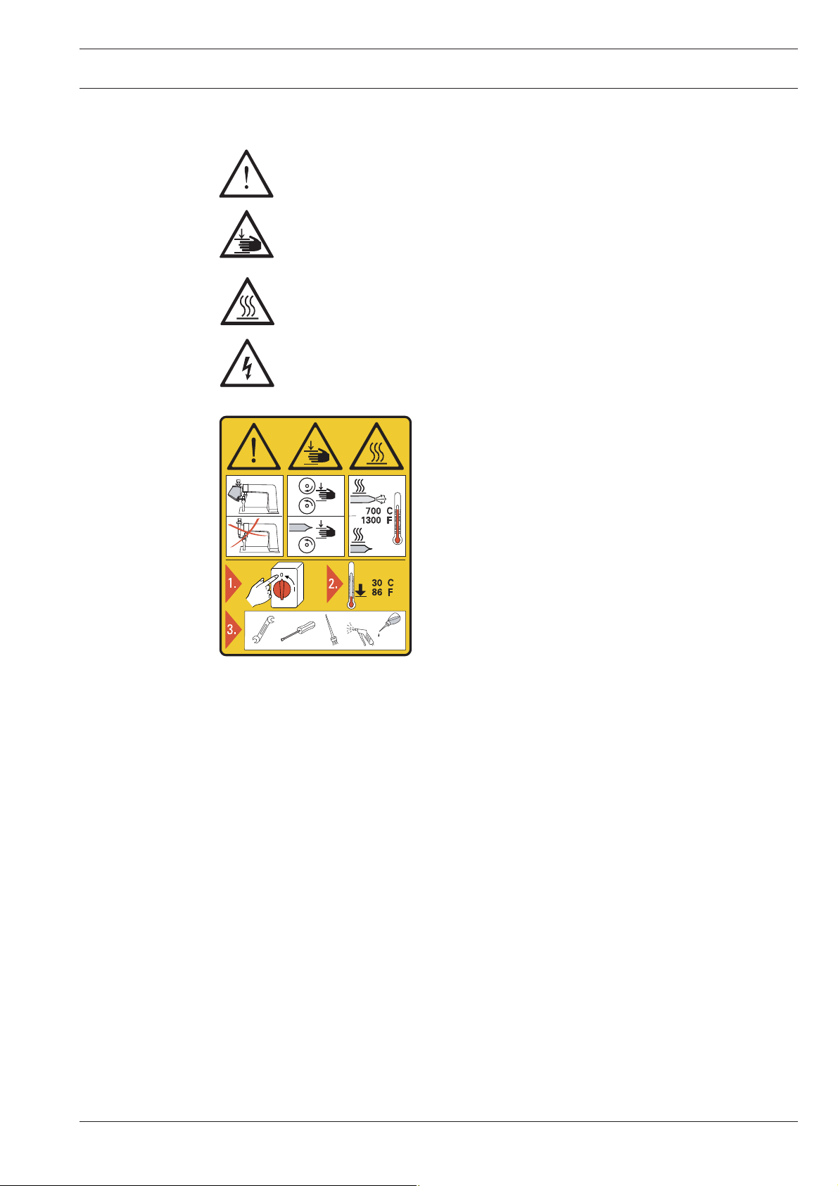
1.03 Safety symbols
Danger!
Special points to observe.
Danger of hands being crushed!
Danger of burns from hot surface!
Danger from electric voltage!
Caution
Do not operate without fi nger guard and safety
devices.
1.04 Important notes for the user
● This instruction manual belongs to the equipment of the machine and must be available
to the operating staff at all times.
● This instruction manual must be read before the machine is operated for the fi rst time.
● Both operating and technical staff must be instructed on the safety devices of the machi-
ne and on safe working methods.
● It is the duty of the user to operate the machine in perfect running order only.
● The user must ensure that none of the safety devices are removed nor put out of wor-
king order.
Turn off the main switch and let the machine cool
down before any setting up, maintenance or cleaning
work!
● The user must ensure that only authorized persons operate and work on the machine.
● The user must make sure there is no high-frequency welding equipment being operated
in direct proximity to the machine that exceeds the EMC limit values according to
EN 60204-31 for the machine.
For further information please refer to your PFAFF agency.
7
Page 8

Safety
1.05 Operating and technical staff
1
1.05.02 Technical staff
.05.01 Operating staff
Operating staff are the persons responsible for setting up, operating and cleaning the machi-
ne and for removing any disturbances in the sewing area.
The operating staff is obliged to observe the following points, and must:
● always observe the notes on safety in this instruction manual!
● avoid using any working methods which adversely affect the safety of the machine!
● avoid wearing loose-fi tting clothing or jewelry such as necklaces or rings!
● also ensure that only authorized persons are allowed near the danger area of the machine!
● immediately report to the user any changes to the machine that may affect its safety!
Technical staff are persons who have been trained in electrical engineering, electronics and
mechanical engineering. They are responsible for lubricating, servicing and repairing the ma-
chine.
The technical staff is obliged to observe the following points, and must:
● always observe the notes on safety in this instruction manual!
● switch off the on/off switch before carrying out any maintenance and repair work on the
machine!
● never work on parts or equipment still connected to the power supply! Exceptions to this
are only permissible according to regulations EN 50110.
● replace all safety covers after maintenance and repair work!
8
Page 9
Safety
1.06 Danger
When the machine is in operation, a work area of 1 m must be kept free in front
of and behind the machine, so that access to the machine is possible at all ti-
mes without diffi culty.
If toxic vapours occur during processing, use extractor (extraction funnel,
part no. 95-255 841-71/895)!
Danger to health if the toxic vapours are inhaled!
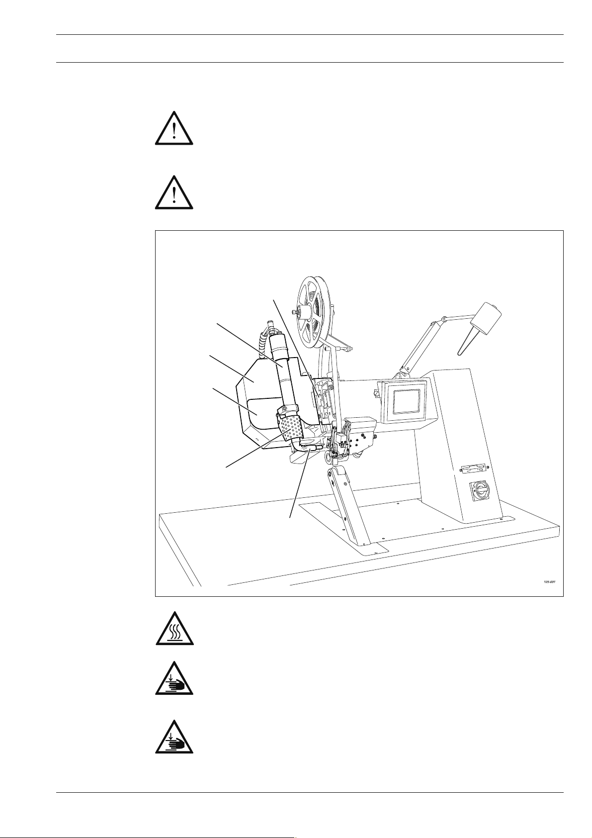
5
6
Fig. 1 - 01
3
4
1
2
Do not operate the machine without protective cover 1!
Danger of burns if heating element 2 is touched!
Do not operate the machine without protective covers 3, 4 and 5!
Danger of crushing when the heating element 2 is engaged or disengaged!
Do not place hands in the swivel area of the heating element 2 and the
swivel unit 6 !
Danger of crushing when the heating element is engaged or disengaged!
9
Page 10

Proper use
2 Proper use
The PFAFF 8330 is a hot-air tape sealing machine with post.
The machine is used to seal seams on waterproof and breathable membrane materials of all
kinds with a heat-sealing tape.
Any and all uses of this machine which have not been approved of by the
manufacturer are considered to be inappropriate! The manufacturer cannot be
held liable for any damage caused by the inappropriate use of the machine!
The appropriate use of the machine includes the observance of all operational,
adjustment, maintenance and repair measures required by the manufacturer!
10
Page 11

Specifi cations
3 Specifi cations ▲
Dimensions and weight:
Length: .......................................................................................................... approx. 1250 mm
Width: .............................................................................................................. approx. 700 mm
Height: (without tape holder): ....................................................................... approx. 1400 mm
Clearance width: ............................................................................................. approx. 380 mm
Clearance between rollers: ............................................................................... approx. 20 mm
Working air pressure: ................................................................................................. min. 5 bar
Air consumption: .................................................................................................30 – 150 l/min
Sealing speed: ................................................................................................. max. 7 m/min.◆
Sealing temperature: .............................................................................................. max. 650°C
Connection data:
Mains voltage (set for): ..........................................................230 V ± 10%, 50/60 Hz, 1 phase
Power input: .....................................................................................................approx. 3500 W
Heating capacity: .............................................................................................approx. 3300 W
Fuse: .................................................................................................................................. 16 A
Leakage current ........................................................................................................... < 5 mA
◆
Noise data:
Emission sound level at the workplace: ............................................................. L
<70 dB(A)
pA
(Noise measurement in acc. with DIN 45 635-48-A-1, ISO 11204, ISO 3744, ISO 4871)
Ambient temperature
85% rel. humidity (condensation not permitted): ...................................................... 5 – 40° C
Net weight: ........................................................................................................approx. 120 kg
▲
Subject to alterations
■
KpA = 2,5 dB
◆
Due to the use of network fi lters there is a nominal leakage current of < 5 mA.
■
11
Page 12

Disposal of Machine
4 Disposal of Machine
● Proper disposal of the machine is the responsibility of the customer.
● The materials used for the machine are steel, aluminium, brass and various plastic
materials. The electrical equipment comprises plastic materials and copper.
● The machine is to be disposed of according to the locally valid pollution control regula-ti-
ons; if necessary, a specialist ist to be commissioned.
Care must be taken that parts soiled with lubricants are disposed of separately
according to the locally valid pollution control regulations!
12
Page 13

Transportation, packing and storage
5 Transportation, packing and storage
5
.01 Transportation to customer‘s premises
The machines are delivered completely packed.
5.02 Transportation inside the customer‘s premises
The manufacturer cannot be made liable for transportation inside the customer‘s premises
nor to other operating locations. It must be ensured that the machines are only transported
in an upright position.
5.03 Disposal of packing materials
The packing materials of this machine comprise paper, cardboard and VCE fi bre. Proper dis-
posal of the packing material is the responsibility of the customer.
5.04 Storage
If the machine is not in use, it can be stored as it is for a period of up to six months, but It
should be protected against dust and moisture.
If the machine is stored for longer periods, the individual parts, especially the surfaces of
moving parts, must be protected against corrosion, e.g. by a fi lm of oil.
13
Page 14

Explanation of symbols
6 Explanation of symbols
In this instruction manual, work to be carried out or important information is accentuated by
symbols. These symbols have the following meanings:
Note, information
Cleaning, care
Lubrication
Maintenance, repairs, adjustment, service work
(only to be carried out by technical staff)
14
Page 15
Controls
7 Controls
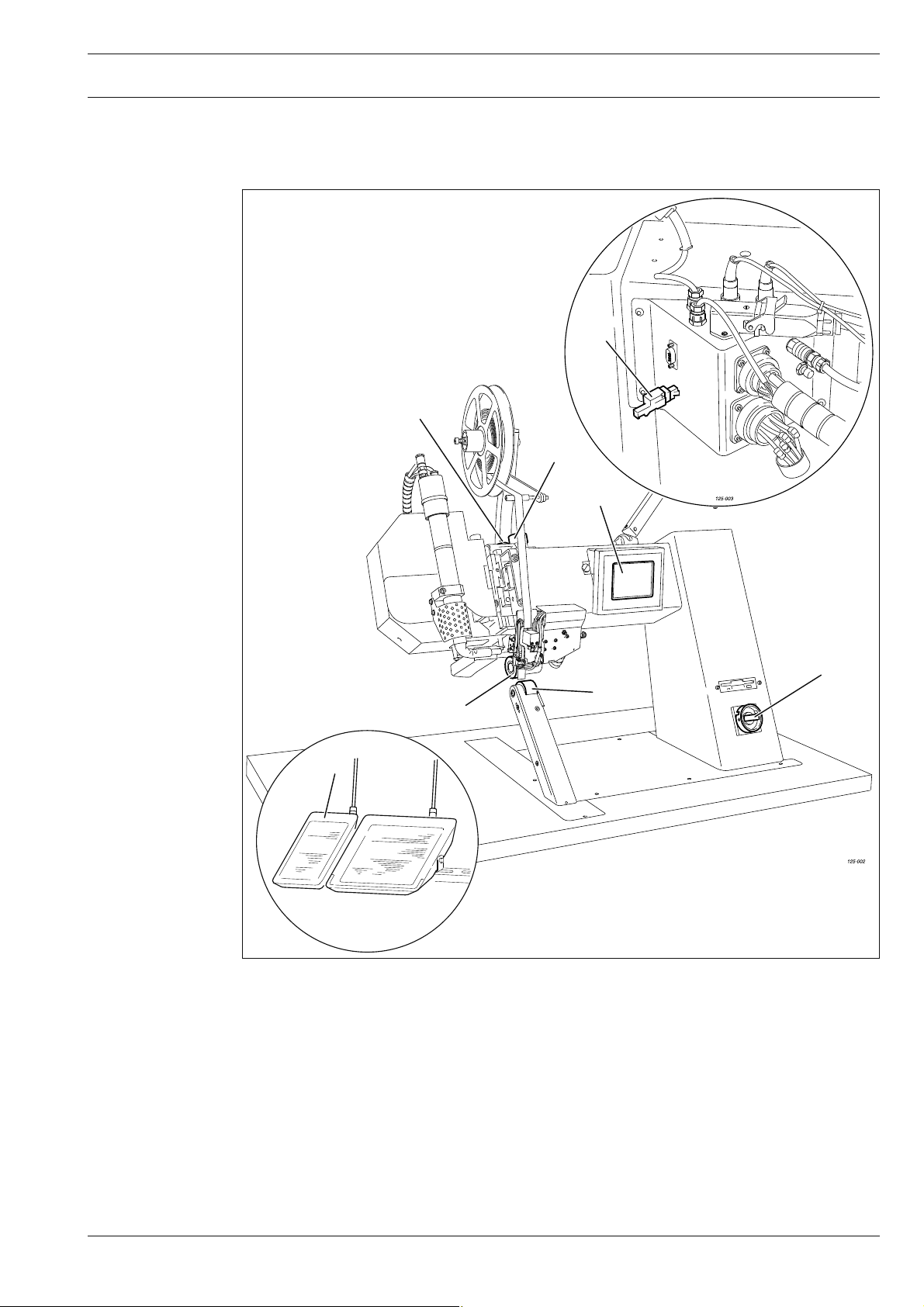
7
.01 Summary of controls
8
4
3
5
7
6
2
Fig. 7 - 01
● Main switch, see Chapter 7.02
● Pedal 2, see Chapter 7.03
● Adjustment wheel 3 for roller clearance, see Chapter 7.04
● Lift limiter 4, see Chapter 7.05
● Control panel 5, see Chapter 7.06
1
● Top feed roller 6
● Bottom feed roller 7
● Key-switch, see Chapter 11 .04.02 Rights of access
15
Page 16
Controls
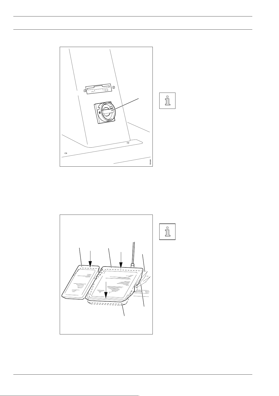
7.02 Main switch
● The machine is switched on or off by tur-
ning main switch 1.
Position "0" : Machine is switched off
Position "1" : Machine is switched on
After the machine has been
1
switched on, fi rst of all the
"basic position" function must
be pressed, see Chapter 8.03
Switching the machine on/off.
Fig. 7 - 02
7.03 Pedal
+3
The function method of the pedal
depends on the selected
pedal mode (level or fl ip-fl op
mode), see Chapter 11 .04 Further
0
settings
+1
0 = neutral position
1 = lower top feed roller
+
+2 = engage heating element /
sealing start
+3 = Cut tape / switch to cold or hot press
-1 = stop sealing operation /
+2
raise top feed roller
16
-1
Fig. 7 - 03
Page 17
Controls
7.04 Adjustment wheel for the roller clearance
● Turn adjustment wheel 1 to change the
1
distance between the top and bottom
feed roller.
The clearance can be read on the scale.
Fig. 7 - 04
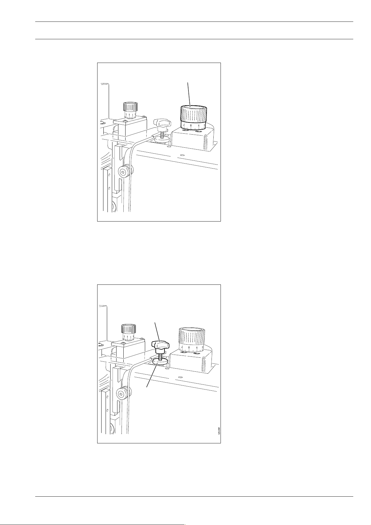
7.05 Lift limiter
● After loosening knurled nut 1, adjust the
top lift limit of the feed roller by turning
screw 2.
2
1
Fig. 7 - 05
17
Page 18
Controls
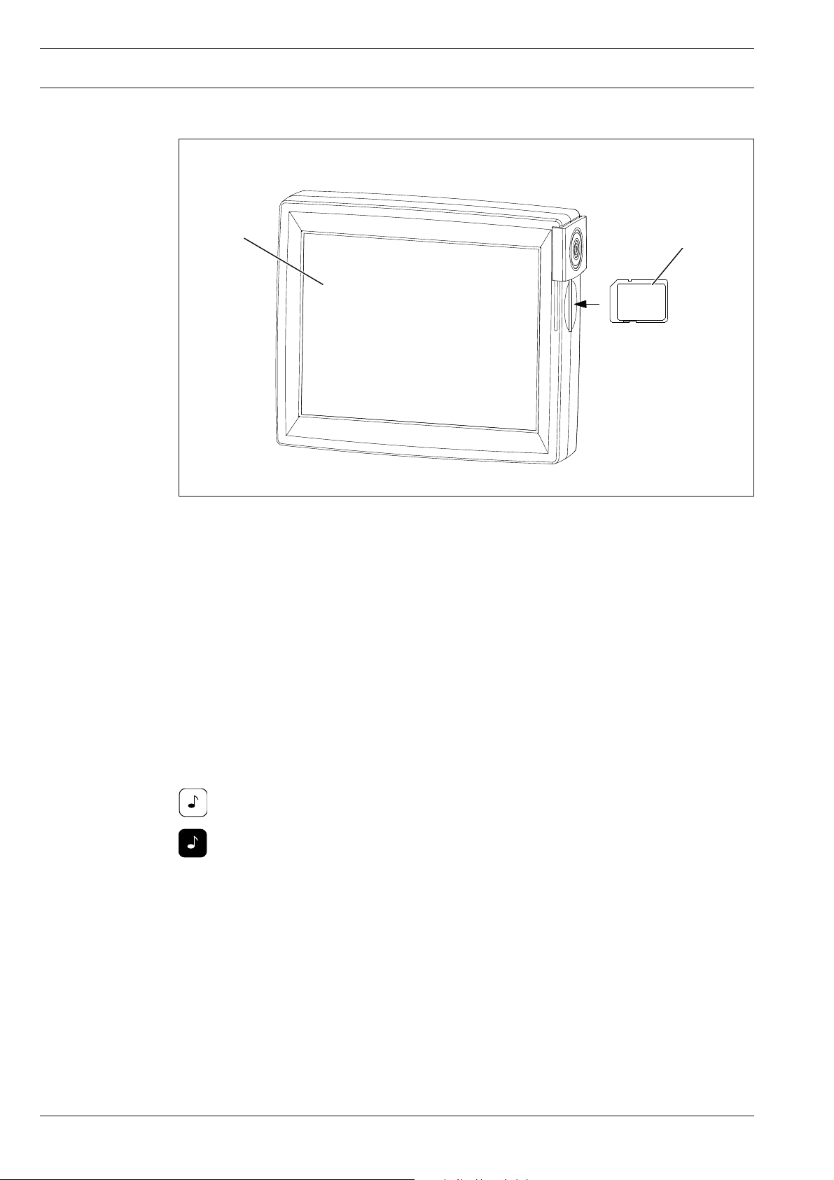
7.06 Control panel
1
2 GB
max.
Fig. 7 - 06
The current operating conditions are displayed on control panel 1. Operation takes place in a
constant dialogue between the control unit and the operator. For this purpose, depending on
the operating condition of the machine, different symbols and/or texts are displayed. If the
symbols or texts are framed, these show functions which can be selected by pressing the
appropriate position on the monitor. By pressing the corresponding function this is carried
out or switched on or off immediately, or a further menu appears, e.g. for entering a value.
Activated functions are shown with inverted symbols. Unframed symbols or texts are only
used for display purposes and cannot be selected by pressing.
To read programs or to install machine software, use the sd-card 2 in the control
panel.
2
18
Description of the functions
Normal symbol = function switched off (inactive)
Inverted symbol = function switched on (active)
Page 19
Installation and commissioning
8 Installation and commissioning
The machine must only be mounted and commissioned by qualifi ed personnel!
All relevant safety regulations are to be observed!
8.01 Installation
The site where the machine is installed must be provided with suitable connections for the
electric current, see Chapter 3 Specifi cations.
It must also be ensured that the standing surface of the machine site is fi rm and horizontal,
and that suffi cient lighting is provided.
The method of packaging used requires that the table top be lowered for trans-
port. The following is a description of how to adjust the height of the table top.
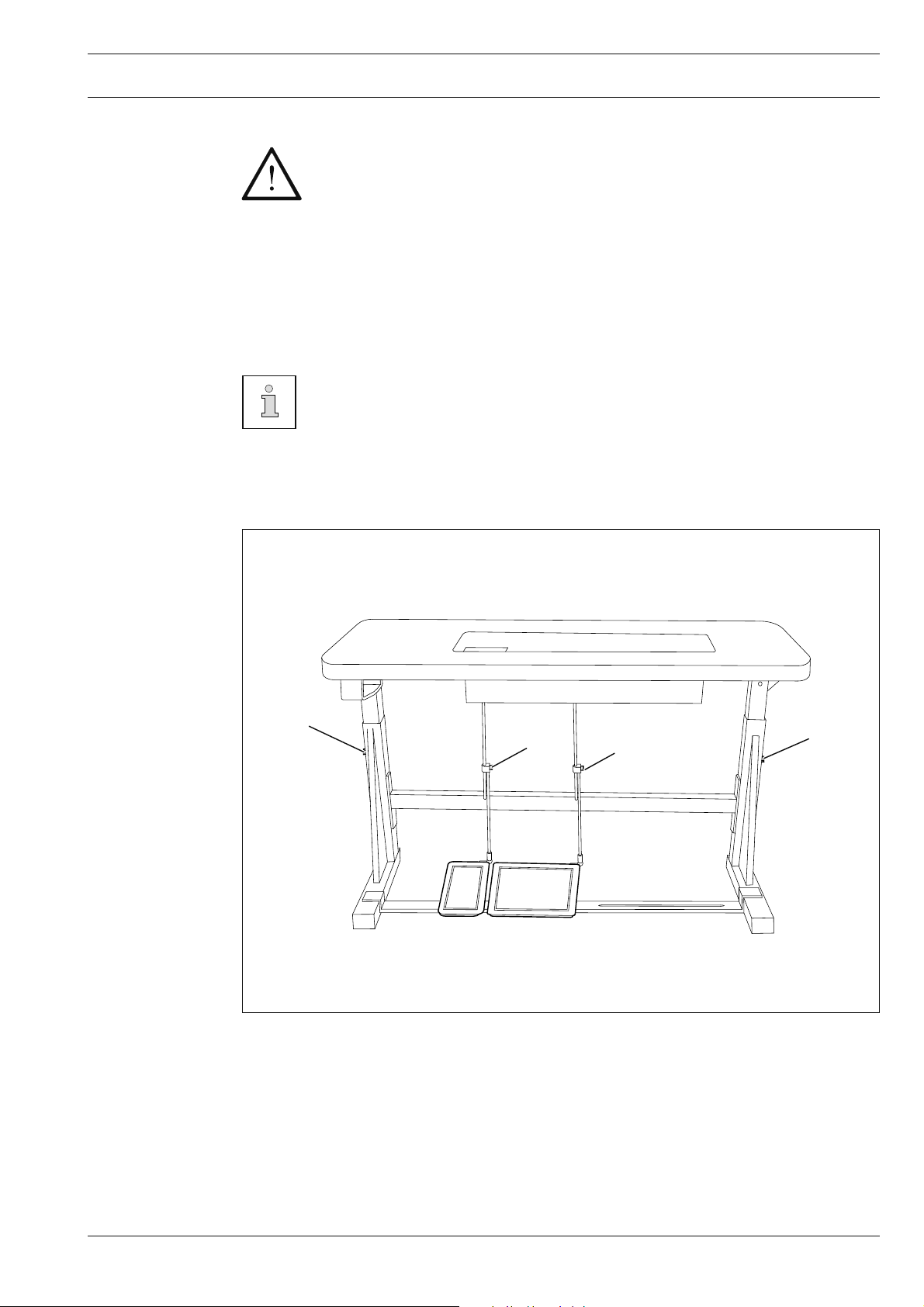
8.01.01 Adjusting the table-top height
1
2
Fig. 8 - 01
● Loosen screws 1 and 2 and set the desired table-top height
● Tighten screws 1 well.
● Adjust the position of the pedal so that you can operate it comfortably and tighten screw 2.
2
1
19
Page 20

Installation and commissioning
8.01.02 Fitting the sealing tape reel holder
1
2
2
Fig. 8 - 02
● Fasten sealing tape reel holder 1 with screws 2.
8.02 Commissioning
● Before commissioning the machine clean it thoroughly, see Chapter 12 Care and Main-
tenance!
● Check the machine, in particular the electric cables and the pneumatic connection tubes,
for any damage.
● Have a qualifi ed person check whether the motor can be driven with the existing power
voltage.
If there are any differences, the machine must defi nitely not be operated!
The machine must only be connected to a suitably earthed socket!
● Connect the machine to the compressed air system. A pressure of 6 bar should be dis-
played on the manometer. If necessary, set this value, see Chapter 12.03 Checking /
adjusting the air pressure.
20
The air must be completely oilfree and dry.
The compressed air quality infl uences the service life of the heating cartridge
in the air heater. If the air is very damp, a compressed air cold drier with
preliminary fi lter and seccondary fi ne fi lter must be installed in front of the
heat-sealing machine.
Page 21
Installation and commissioning
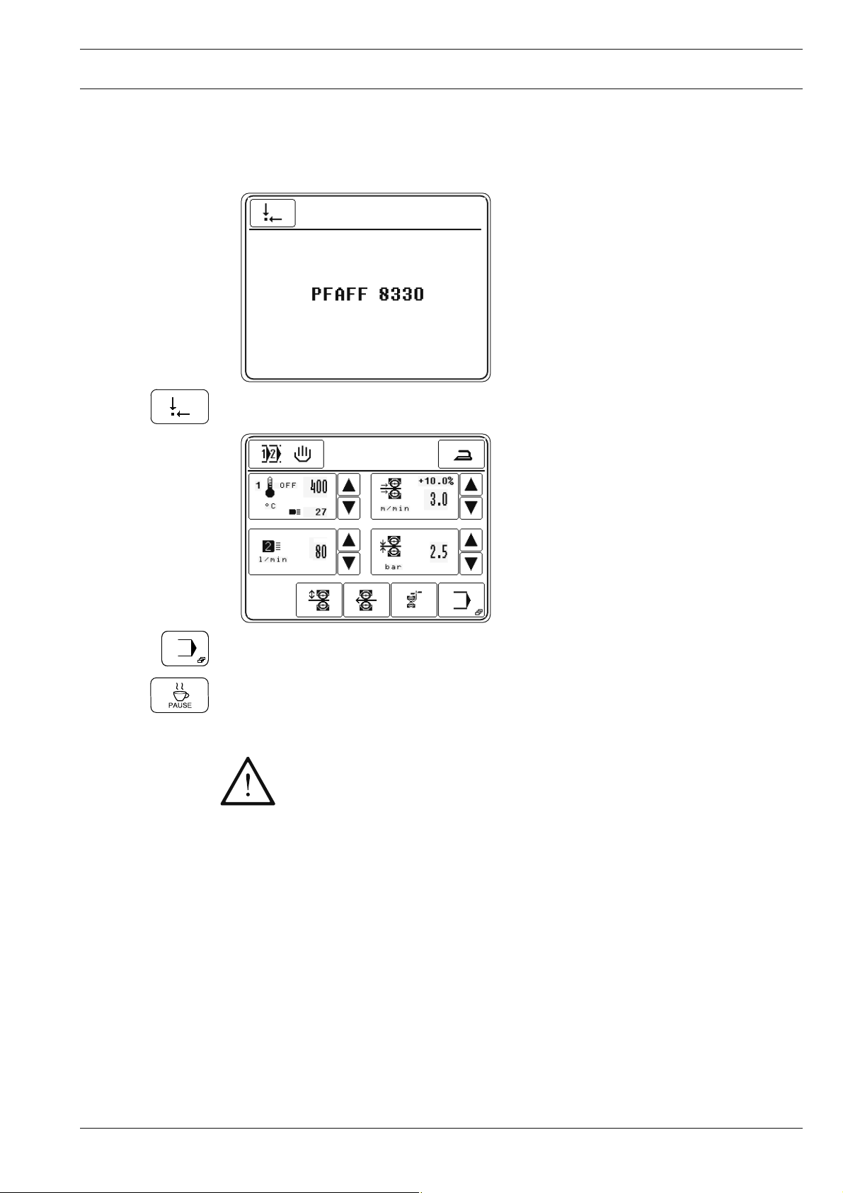
8.03 Switching the machine on/off
● To switch on the machine, turn the main switch to the "I" position, see Chapter 7.02 Main
switch.
● After the boot operation of the control unit, call up the "basic position" function.
● To switch off the machine, call up the input function.
● Call up the "pause" function and wait until the blast air switches off automatically.
Danger of damage to the heating cartridge!
The hot air temperature must not exceed 100°C when switched off!
Before switching off the compressed air system, wait until the blast air swit-
ches off automatically!
● Turn the main switch to the "0" position, see Chapter 7.02 Main switch.
21
Page 22
Installation and commissioning
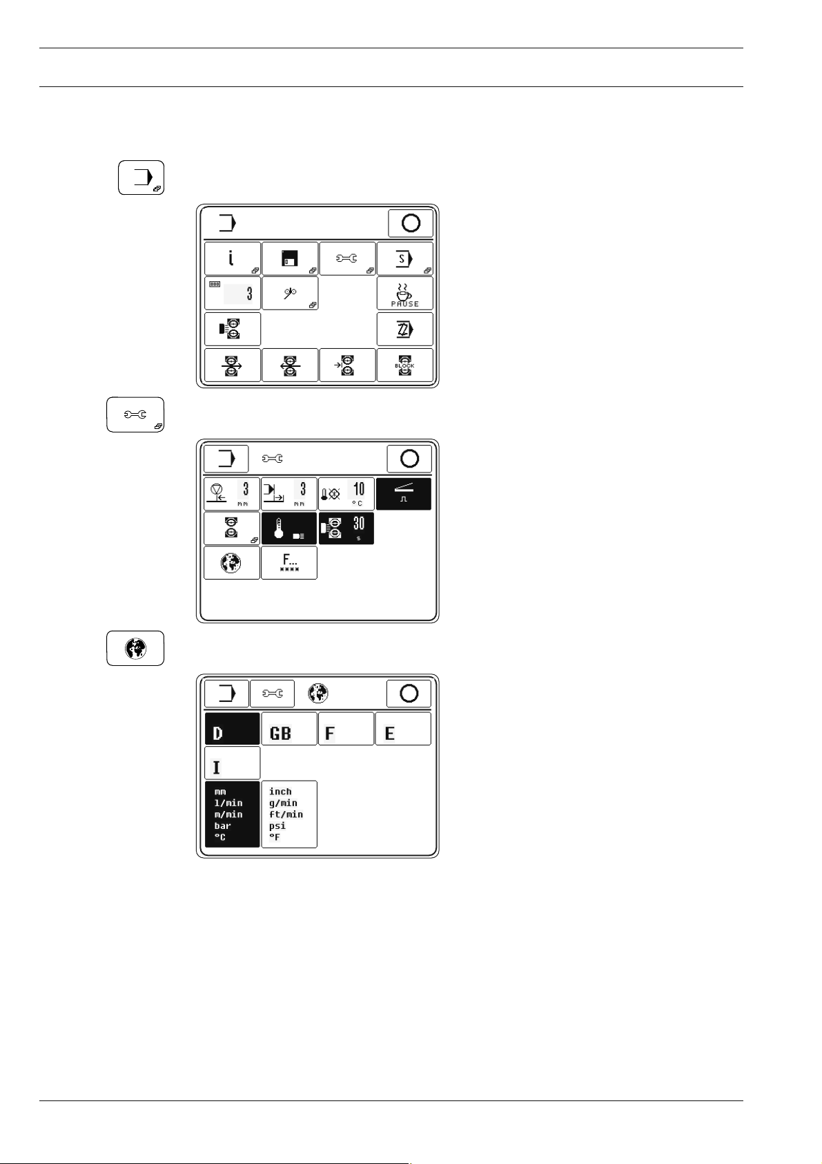
8.04 Selecting the language and units
● Switch on the machine, see Chapter 8.03 Switching the machine on/off.
● Call up the input menu.
● Call up the settings menu.
● Call up the "language setting" menu.
● Select the appropriate language and units.
22
Page 23
Preparation
9 Preparation
All regulations and notes in this Service Manual must be observed!
Special attention must be paid to the safety regulations!
All setting-up work must only be carried out by personnel with the appropriate
training!
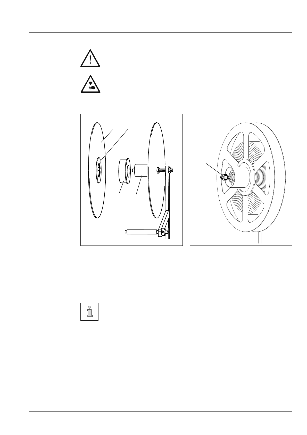
9.01 Inserting the sealing tape
1
2
5
4
Fig. 9 - 01
The sealing tape real holder must be adapted to the inner diameter of the sealing tape reel:
● For small inner diameters turn the front disk 1, so that the small disk 2 is positioned op-
posite holder 3. The sealing tape reel can be fi tted to the holder directly.
3
100-014
Fig. 9 - 02
● For large inner diameters turn the front disk 1, so that the large disk 2 is positioned oppo-
site holder 3. Slide fi tting 4 onto holder 3 and push the sealing tape reel onto it.
When the sealing tape unwinds it should not touch the inner wall of the sealing
tape reel holder.
9.01.02 Adjusting the sealing tape brake
● Adjust the sealing tape brake with nut 5 so that the sealing tape reel cannot continue mo-
ving, but the sealing tape can be drawn off rapidly.
23
Page 24
Preparation
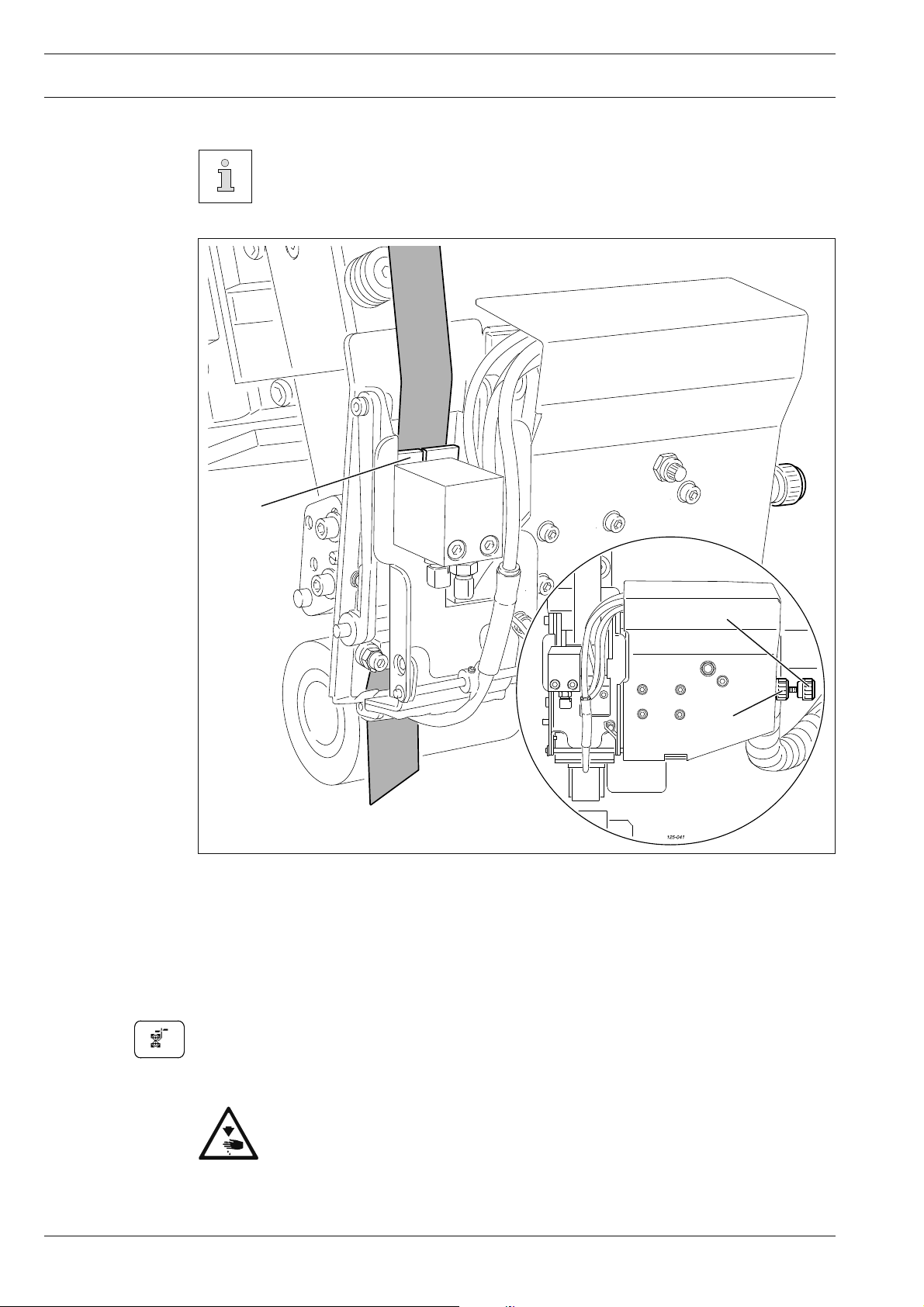
9.01.03 Inserting the sealing tape
The sealing tape should run in the centre of the feed rollers and be guided in a
narrow channel but still run easily through the guide.
2
3
1
Fig. 9 - 03
● Switch on the machine.
● Loosen knurled nut 1 and adjust guide unit 2 with knurled screw 3.
● Tighten knurled nut 1.
● Cut the sealing tape at a slant and lead it through guide unit 2, until it becomes visible un-
der unit 2.
● Start a cutting operation.
The sealing tape is drawn in and cut.
24
Danger of injury from the tape knife!
Do not touch the tape cutting device by hand!
Use tweezers!
Page 25
Preparation
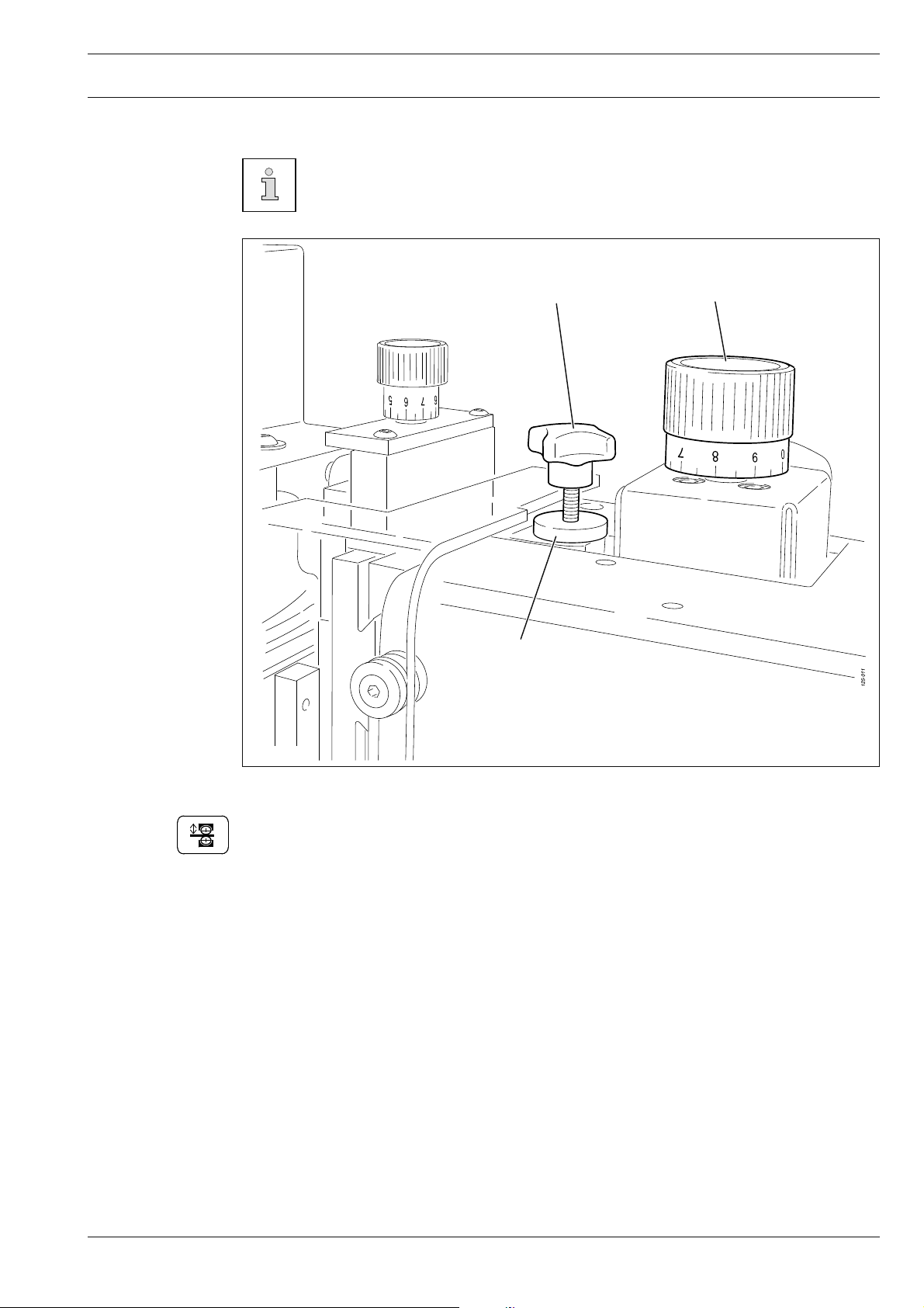
9.02 Adjusting the feed roller clearance
The feed roller clearance depends on the thickness of the material to be sealed.
The clearance is adjusted correctly, when one ply of the workpiece fi ts just bet-
ween the feed rollers when the top feed roller is lowered.
3
1
2
Fig. 9 - 04
● Switch on the machine.
● Lower the top feed roller.
● Adjust the clearance between the rollers with adjustment wheel 1 depending on the
workpiece and sealing method, see Chapter 7.04 Adjustment wheel for roller clearance.
● Loosen knurled nut 2.
● Set the lift limit to match the sealing material and application using cross handle screw 3.
● Tighten knurled nut 2.
25
Page 26
Preparation
9.03 Selecting the production type
The program selection function is used to choose between the types of production
- Manual heat sealing (Chapter 10.02)
- Programmed heat sealing with individual programs (Chapter 10.05)
- Programmed heat sealing with sequences (Chapters 10.07) and
- Dynamic sealing (see Chapter 10.03).
The types of production listed above, particularly their functions, are explained
in more detail in Chapter 10 Heat sealing.
● Switch on the machine.
2x
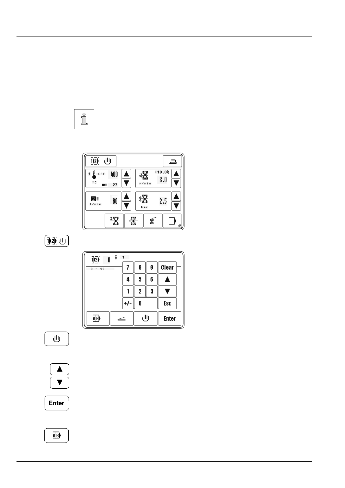
● Call up program selection.
● Call up manual heat sealing, the production type, "Manual Heat Sealing" is activated.
or
● Select the desired program number.
(Selection can also be made by entering the program number on the fi gure panel directly.)
● Confi rm selection and quit selection menu, die production type "Programmed Heat
Sealing with individual program" is activated.
26
or
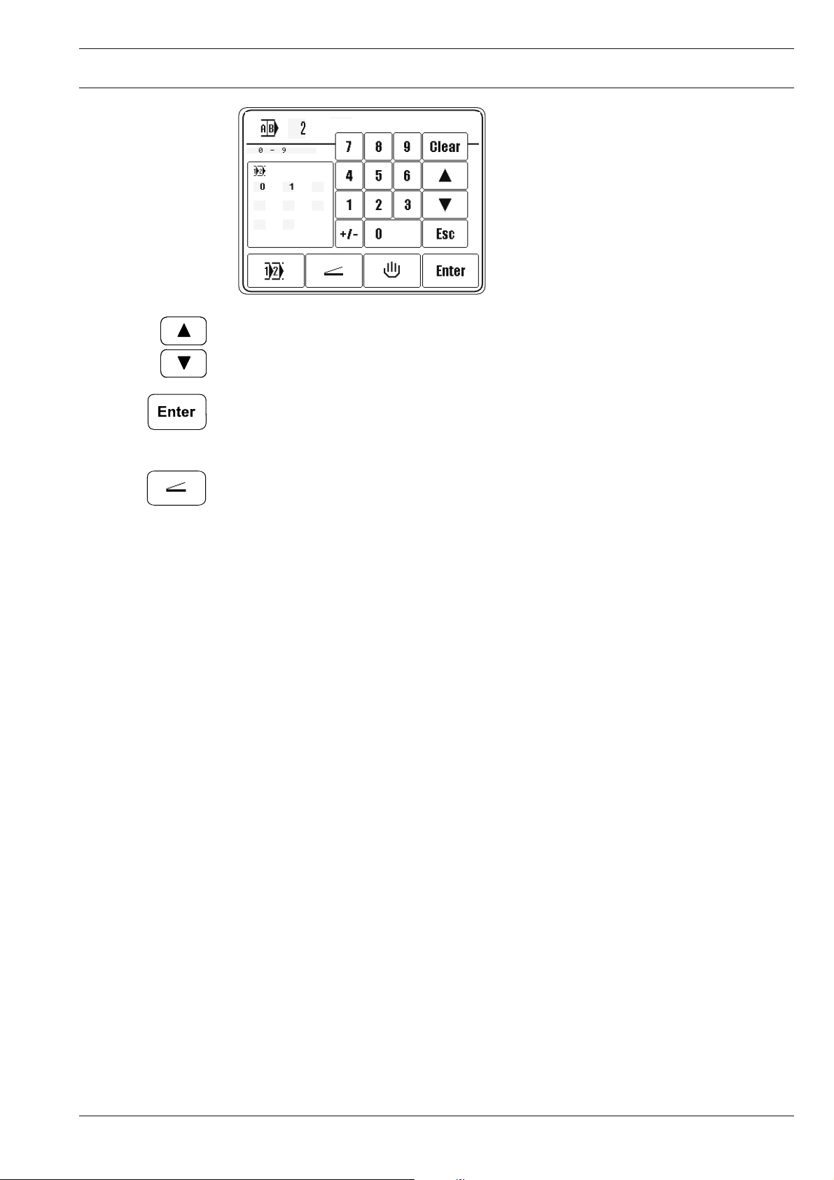
● Call up sequence selection.
Page 27
Preparation
● Select desired sequence number.
(Selection can also be made by entering the sequence number on the fi gure panel directly.)
● Confi rm selection and quit selection menu, die production type "Programmed Heat
Sealing with sequence program" is activated.
or
2x
● Call up Dynamic Sealing, the "dynamic sealing" production type is activated.
27
Page 28
Preparation
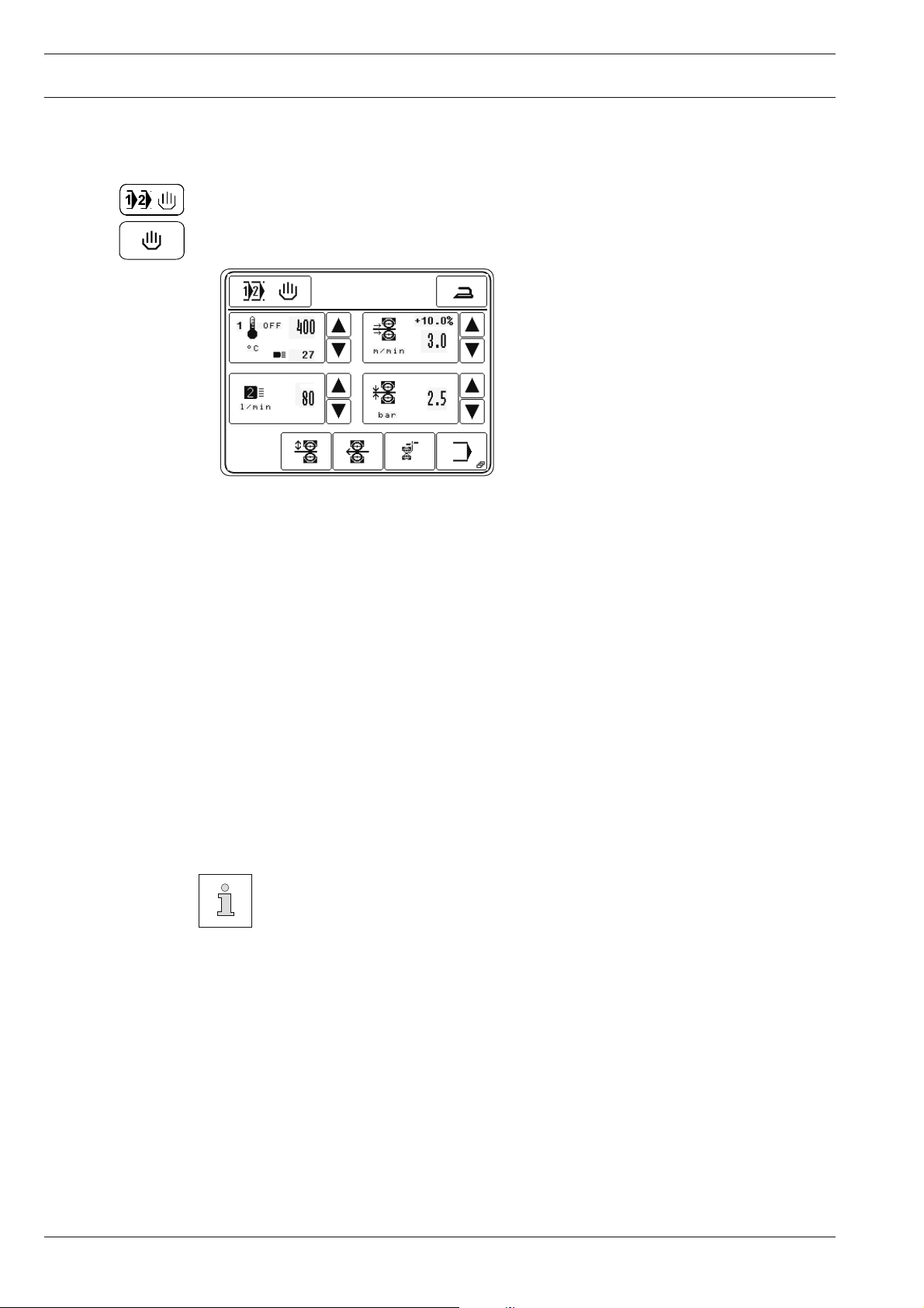
9.04 Entering the sealing parameters (Manual Heat Sealing)
● Switch on the machine.
● Call up program selection.
2x
● Call up manual heat sealing.
After selecting "Manual Heat Sealing", also see Chapter 9.03 Program Selection, following
values can be entered depending on the sealing method:
- Sealing temperature
In addition to the set sealing temperature, the values for the regulation ratio
(off = heating off) and the current actual temperature appear in the appropriate symbol.
- Sealing speed
In addition to the sealing speed, the value for the difference in speed in % between the
top and bottom feed rollers appears in the appropriate symbol.
- Type of heating nozzle with hot air volume
- Roller pressure
28
The values can be entered directly by pressing the appropriate key symbol.
In Programmed Heat Sealing the direct input of sealing parameters is not
possible. The alteration must be made in the appropriate sealing program, see
Chapter 10.04 Creating/editing a heat sealing program.
Page 29
Preparation
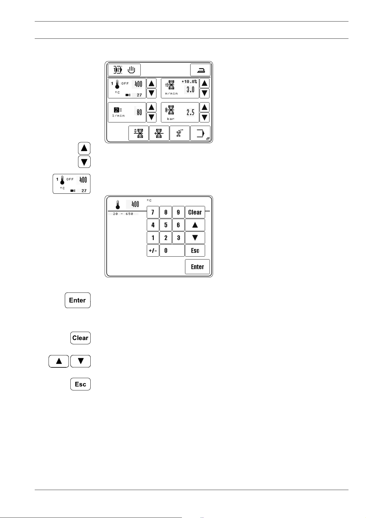
9.04.01 Entering the sealing temperature
● Increase or reduce the value for the sealing temperature directly.
or
● Call up the fi gure panel to enter the sealing temperature.
● Enter the value for the sealing temperature within the permitted range.
● Conclude the input, permissible values will be taken over.
Description of further functions
Clear
When this function key is pressed, the value is set at "0".
Arrow keys
When these function keys are pressed, the value is increased or reduced.
Esc
When this function key is pressed, the input is cancelled without the value entered being
taken over.
29
Page 30
Preparation
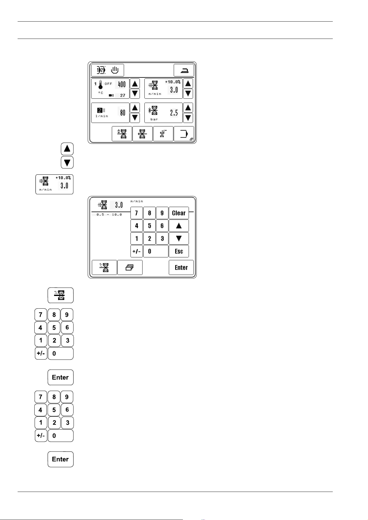
9.04.02 Entering the sealing speed
● Increase or reduce the value for the sealing speed directly.
or
● Call up the fi gure panel to enter the sealing speed.
● If necessary call up the fi gure panel to enter the speed difference between the top and
bottom feed roller.
● Enter the value for the speed difference within the permitted range.
● The speed difference results from the change in speed of the top feed roller, which ro-
tates either more quickly or more slowly than the bottom feed roller. The value for the
speed difference depends on the material and application.
● Conclude the input, permissible values will be taken over.
● Enter the value for the sealing speed within the permissible range.
● Conclude the input, permissible values will be taken over.
30
Page 31

Preparation
Description of further functions
Clear
When this function key is pressed, the value is set at "0".
Arrow keys
When these function keys are pressed, the value is increased or reduced.
Esc
When this function key is pressed, the input is cancelled without the value entered being
taken over
Further parameter
This function key opens a menu for entering the brake and acceleration profi le and for set-
ting the start delay.
9.04.03 Choice of the nozzle type and hot air volume
● Increase or reduce the hot air volume directly.
or
● Call up the menu for selecting the nozzle type or for entering the hot air volume.
● Select the nozzle type in accordance with the width of the nozzle installed.
The symbol for the selected nozzle type appears as an inverse symbol.
Düsentyp Breite der Düse
1
2
3
< 10 mm
10 - 30 mm
> 30 mm
31
Page 32

Preparation
● Using the number block, enter the value for the hot air volume within the permitted ran-
ge.
● Conclude the input, permissible values will be taken over.
Description of further functions
Clear
When this function key is pressed, the value is set at "0".
Arrow keys
When these function keys are pressed, the value is increased or reduced.
Esc
When this function key is pressed, the input is cancelled without the value entered being
taken over
9.04.04 Entering the roller pressure
● Increase or reduce the roller pressure directly.
or
● Call up the number panel to enter the roller pressure.
● Enter the roller pressure within the permitted range.
32
● Conclude the input, permissible values will be taken over.
Page 33

Preparation
9.05 Adjusting the control panel
● Switch on the machine.
● Call up the input menu.
● Select the service menu.
● Select control panel functions.
● Change the display contrast.
● Change the display contrast.
Never reduce the display contrast to the extent, that the display can no
longer be read!
33
Page 34

Heat sealing
10 Heat sealing
The machine may only be operated by properly instructed personnel. The opera-
ting personnel must make sure that only authorised persons are in the danger
zone of the machine.
In particular for production, in addition to the input menu (see Chapter 11 Input), the „heat
sealing“ mode is available, in which, irrespective of the program selected and the machine
status, all functions and settings relevant for the sealing operation are shown on the display.
With the program selection function, following production types can be selected in the "heat
sealing" mode, see Chapter 9.03 Selecting the production type:
Manual heat sealing, see Chapter 10.02
Dynamic sealing, see Chapter 10.03
Programmed heat sealing with individual programs, see Chapter 10.05
Programmed heat sealing with sequences, see Chapter 10.07
10.01 Heat sealing principle
To achieve optimum sealing results, certain conditions must be fulfi lled with regard to mate-
rial and machine setting.
The material must:
- be heat-sealable,
- suitable for being processed by the machine with regard to thickness and structure and
- and match the sealing tape.
In the seam area, the material to be heat sealed must be clean and free from separating
agents, such as e.g. oil or silicone.
The basic conditions depending on the sealing device are:
- correct hot air temperature (sealing temperature);
- correct setting for the hot air nozzle;
- correct setting for the hot air volume;
- correct choice of feed rollers (silicone or steel);
- optimum pressure of the feed rollers on the material being sealed (roller pressure);
- correct distance between the feed rollers and
- correct sealing speed (feed stroke).
34
All the settings of the heat-sealing device are principally dependent on the ma-
terial being sealed and the ambient temperature. Due to the infl uence of the in-
dividual operating parameter on each other, it is only possible to determine the
optimum setting values by carrying out test sealing operations.
Page 35

Heat sealing
10.02 Manual heat sealing
In the "Manual heat sealing" mode, all relevant parameters for the sealing operation can
be entered or altered directly, see Chapter 9.04 Entering the sealing parameters (manual
heat sealing).
2x
● Select "manual heat sealing", see Chapter 9.03 Selecting the production type.
Description of the functions
Selecting a program
This function opens the menu for entering the program number or for selecting the production type, see Chapter 9.03 Selecting the production type.
Pressing
This function is used to switch on the pressing function. It is possible to choose between
two pressing functions:
- Cold pressing
- Warm pressing
The pedal function is used to switch between cold and warm pressing, see Chapter 7.03 Pe-
dal. During cold pressing the rollers are closed with the set roller pressure. The rollers roll
over the part without tape, with disengaged hot air nozzle. During cold pressing the speed
can be infi nitely adjusted with the pedal function. The differential is switched off. During
warm pressing, the hot air nozzle is also engaged.
Heat sealing temperature
These functions are used to alter the heat sealing temperature, see Chapter 9.04.01
Entering the sealing temperature.
Feed stroke (sealing speed)
These functions are used to alter the feed stroke or to open the menu for entering the feed
stroke difference, the brake and acceleration profi les and the start delay for the feed rollers,
see Chapter 9.04.02 Entering the sealing speed.
Nozzle type / hot air volume
These functions are used to alter the hot air volume or to open the menu for choosing the
nozzle type, see Chapter 9.04.03 Choice of the nozzle type and hot air volume …
35
Page 36

Heat sealing
Roller pressure
These functions are used to alter the roller pressure, see Chapter 9.04.04 Entering the roller pressure.
Start
(This function appears when the top feed roller is lowered.)
With this function the sealing start is called up, analog to the pedal function "+2", also see
Chapter 7.03 Pedal.
Feed roller up/down
With this function the top feed roller, depending on its position, can be raised or lowered,
analog to the pedal functions "-1" and "+1", also see Chapter 7.03 Pedal.
Feed rollers in reverse
This function makes it possible to call up the reverse running function of the feed rollers.
Tape cutting
This function starts a tape cutting operation.
Input menu
This function is used to call up the Input Menu, see Chapter 11 Input.
Stop
(This function appears during the sealing operation.)
This function is used to stop the sealing operation, analog to pedal function "-1", also see
Chapter 7.03 Pedal.
36
Page 37

Heat sealing
10.03 Dynamic heat sealing
In the dynamic heating sealing mode, all relevant parameters for the sealing operation can
be entered or altered directly, see Chapter 9.04 Entering the sealing parameters (manual
heat sealing). The sealing speed can be infi nitely varied with the pedal functions. The remai-
ning sealing parameters are appropriately adapted to the changing sealing speeds.
2x
● Select dynamic sealing, see Chapter 9.03 Selecting a production type.
Description of the functions
Selecting a program
This function opens the menu for entering the program number or for selecting the production type, see Chapter 9.03 Selecting a production type.
Pressing
This function is used to switch on the pressing function. It is possible to choose between
two pressing functions:
- Cold pressing
- Warm pressing
The pedal function is used to switch between cold and warm pressing, see Chapter 7.03 Pe-
dal. During cold pressing the rollers are closed with the set roller pressure. The rollers roll
over the part without tape, with disengaged hot air nozzle. During cold pressing the speed
can be infi nitely adjusted with the pedal function. The differential is switched off. During
warm pressing, the hot air nozzle is also engaged.
Heat sealing temperature
These functions are used to alter the heat sealing temperature, see Chapter 9.04.01
Entering the sealing temperature.
Feed stroke (sealing speed)
These functions are used to alter top and bottom limit for the feed stroke or to enter the
feed stroke difference.
Nozzle type / hot air volume
These functions are used to alter the top and bottom limit for the hot air volume.
37
Page 38

Heat sealing
Roller pressure
These functions are used to alter the roller pressure, see Chapter 9.04.04 Entering the roller pressure.
Feed roller up/down
With this function the top feed roller, depending on its position, can be raised or lowered,
analog to the pedal functions "-1" and "+1", also see Chapter 7.03 Pedal.
Feed rollers in reverse
This function makes it possible to call up the reverse running function of the feed rollers.
Tape cutting
This function starts a tape cutting operation.
Input menu
This function is used to call up the Input Menu, see Chapter 11 Input.
38
Page 39

Heat sealing
10.04 Creating/editing a heat sealing program
Up to 100 sealing programs (0 – 99) each with up to 20 sealing zones can be fi led and mana-
ged in the machine memory.
● Call up the input menu.
● With the “programming” function from the input menu it is possible to enter the pro-
gramming function for sealing programs. A number block for entering the desired pro-
gram number appears.
Creating a new program
If no program is fi led in the memory under the program number selected, the current
sealing parameter of the manual heat sealing function will be taken over and a new program
created.
As an alternative to the creation of a new program, the program number of an existing program (e.g. 50) can be selected, and this program can be changed or copied to create a new
program. In the case of existing programs, the number of zones and possibly a comment are
displayed next to the program number in the headline.
● Enter the program number, e.g. "50".
Editing a program
● Confi rm selection.
The fi rst zone of the selected program is displayed on the screen with functions for ente-
ring sealing parameters, notes, switching to the next zone, as well as basic functions for the
program input. For further descriptions of the functions see Chapter 10.04.07 Example for
sealing program input.
39
Page 40

Heat sealing
10.04.01 Notepad
When creating a sealing program, this function is used to enter data about the sealing tools
for the program. The data serves as information for the operator and can be called up in the
programmed sealing mode.
● Press the relevant key panels to enter the data.
● Enter the relevant data.
● Conclude the input
40
Page 41

Heat sealing
10.04.02 Basic functions for the program input
The following functions are used to enter the basic information for the currently selected
program. In addition to functions for navigating in the different zones and functions for inser-
ting and deleting zones, depending on the zone displayed, functions can be called up for en-
tering further parameters and comments as well as for concluding the program input.
● Call up the appropriate functions to process or conclude the program.
Description of the functions
Selecting a zone
These functions are used to switch forwards and backwards to other zones in the current
program.
Insert
This function inserts a new zone at the current location. The data of the current zone are co-
pied for the new zone and the following zones are moved one place back.
Delete
This function deletes the current zone.
Further sealing parameters
(This function only appears in the fi rst zone.)
This function opens a menu for entering further sealing parameters.
Comment
(This function only appears in the fi rst zone.)
With this function, when entering a note, see Chapter 10.04.01 Notepad, the analog entry
of a comment about the current program is possible. The comment is displayed as informati-
on about the appropriate program in the program selection and program management func-
tions.
Add
(This function only appears in the last zone.)
This function is used to copy the data of the current zone and add it as a new zone.
Conclude programming
This function concludes the programming, see Chapter 10.04.06 Concluding the program-
ming.
41
Page 42

Heat sealing
10.04.03 Sealing parameters
● Enter sealing parameters for each zone as described in Chapter 9.04 Entering sealing
parameters (manual heat sealing).
Description of the functions
Heat sealing temperature
This function is used to alter the heat sealing temperature, see Chapter 9.04.01 Entering
the sealing temperature.
Feed stroke (sealing speed)
This function is used to open the menu for entering the feed stroke difference, the brake and
acceleration profi les and the start delay for the feed rollers, see Chapter 9.04.02 Entering
the sealing speed.
Nozzle type / hot air volume
This function is used to open the menu for choosing the nozzle type and the hot air volume,
see Chapter 9.04.03 Choice of the nozzle type and hot air volume …
Roller pressure
This function is used to alter the roller pressure, see Chapter 9.04.04 Entering the roller
pressure.
42
Page 43

Heat sealing
10.04.04 Functions for switching to other zones
In addition to the sealing parameters, further functions can be allocated to each zone, which
serve to enable the automatic switch to other zones and a more exact setting of the sealing
operation sequence.
● Select appropriate functions for each zone, activated functions are displayed as inverse
symbols on the screen.
Description of the functions
Programmed section
mm
This function is used to determine the length of the current zone. The value in millimetres is
entered on the appropriate number block. When this function is activated, the machine swit-
ches to the next sealing zone after processing the entered section. In the last sealing zone
the sealing tape is cut to fi t exactly.
Programmed stop
When this function is switched on, the current zone takes on a stop function. The sealing
operation stops and the machine moves to the next zone.
Programmed output
When this function is switched on, the current zone takes on an output switch function. Two
outputs can be stipulated with the appropriate menu.
Programmed input
When this function is switched on, the machine does not switch to another zone until an
appropriate input signal is given or not given. The two different inputs can be set up with the
appropriate menu.
43
Page 44

Heat sealing
10.04.05 Entering further sealing parameters
Further sealing parameters can be entered either
● from the manual resp. dynamic sealing mode in conjunction with the sealing speed input
or
● when creating programs in conjunction with the input of the fi rst zone.
Input from manual
heat sealing mode
● Select acceleration and brake profi le of the feed rollers, dependent on the material for
sealing. Each of the profi les selected is displayed as an inverse symbol. A fl at ramp
stands for slight acceleration of the feed rollers. The selection of a steep ramp means
high acceleration.
If the sealing result is unsatisfactory, the alteration of the acceleration or brake
profi le can lead to an improvement.
The values of the different acceleration and brake profi les can be stipulated in
the input mode, see Chapter 11 .03.01 Feed roller parameters.
Input while
creating programs
● Increase or reduce the start delay for the feed rollers directly.
or
● Call up the fi gure panel to enter the start delay.
Enter the start delay depending on the material being processed.
● Conclude the input, permissible values will be taken over.
The start delay function is used to stipulate the amount of time which should
pass between the engaging of the heating element and the start of the feed
rollers.
44
Page 45

Heat sealing
Further functions are available for creating programs:
● This function opens a menu for entering the tape parameters, see Chapter 11 .03.02 Tape
parameters.
● Select the nozzle type in accordance with the width of the nozzle installed, see Chapter
9.04.03 Choice of the nozzle type and hot air volume …
10.04.06 Concluding programming
Once all the details for programming have been entered, the programming can be concluded
by pressing the appropriate function key.
Save
as...
Description of the functions
Esc
The input is interrupted and the machine moves back to the basic programming condition.
Discard alterations
All program alterations are cancelled.
Save as…
If this function key is pressed, the number panel opens to enter any program number.
Enter
All program alterations are saved under the current program number.
45
Page 46

Heat sealing
10.04.07 Example of how to enter a sealing program
The following example should be fi led under program number "10" with the comment
"EXAMPLE 1", and consists of three seam zones:
- Seam zone 1 with switch to another zone after 200 mm seam length
- Seam zone 2 with reduced sealing speed and speed difference between the top and
bottom feed roller, and switch to another zone after 10 0 mm
- Seam zone 3 with original sealing speed without speed difference between the feed
rollers and with switch to another zone after 400 mm
● Switch on the machine.
● Call up the input menu.
● Call up the programming function.
● Enter program number "10".
● Confi rm input.
The sealing parameters from the manual sealing mode are taken over for the 1
zone.
st
seam
46
Page 47

Heat sealing
● Call up comment input.
● Enter the term "EXAMPLE" with the appropriate symbols.
● Change to number input.
● Enter number "1" with the appropriate symbol.
● Conclude the comment input.
mm
● Activate the switch to another zone using the seam length.
● Enter the value "200" as seam length with the number panel.
● Conclude the activated function for switching to another zone.
47
Page 48

Heat sealing
● Add seam zone 2.
● Change the values for sealing speed and speed difference.
● Activate the switch to another zone with the value "100" as seam length.
mm
● Conclude the input of seam zone 2.
48
Page 49

Heat sealing
● Add seam zone 3.
● Reset the values for sealing speed and speed difference.
mm
● Activate the switch to another zone with the value "400" as seam length.
● Conclude the input of seam zone 3.
● Conclude programming.
● Reconfi rm the sealing program input.
The programmed sealing function is called up to process the created sealing program.
49
Page 50

Heat sealing
10.05 Programmed heat sealing with individual programs
In the headline, in addition to the program number of the selected program, the number
of zones, the current zone and the comment for the program are displayed. For the current
zone all heat-sealing parameters are displayed. The heat-sealing parameters have been
entered during programming and cannot be altered without changing the program.
● Select the desired program, see Chapter 9.03 Selecting a production type.
Description of the functions
Program selection
The function opens the menu for entering the program number or for choosing the production type, see Chapter 9.03 Selecting a production type.
Notepad
This function opens the notepad with program details about the heat-sealing tools to be
used.
Pressing
This function is used to switch on the pressing function. It is possible to choose between
two pressing functions:
- Cold pressing
- Warm pressing
The pedal function is used to switch between cold and warm pressing, see Chapter 7.03 Pe-
dal. During cold pressing the rollers are closed with the set roller pressure. The rollers roll
over the part without tape, with disengaged hot air nozzle. During cold pressing the speed
can be infi nitely adjusted with the pedal function. The differential is switched off. During
warm pressing, the hot air nozzle is also engaged.
Start
(This function appears, when the top feed roller is lowered.)
This function is used to call up the sealing start, analog to pedal function "+2", also see Chapter 7.03 Pedal.
50
Feed roller up/down
This function is use to raise or lower the top feed roller, depending on its position, analog to
the pedal functions "-1" and "+1", also see Chapter 7.03 Pedal.
Page 51

Heat sealing
Feed rollers in reverse
This function makes it possible to call up the reverse running function of the feed rollers.
Tape cutting
This function starts a tape cutting operation (Reference cut).
Input menu
This function is used to call up the Input Menu, see Chapter 11 Input.
Stop
(This function appears during the sealing operation.)
This function is used to stop the sealing operation, analog to pedal function "-1", also see
Chapter 7.03 Pedal.
51
Page 52

Heat sealing
10.06 Creating/processing sequences
In sequences up to 8 heat sealing programs are combined in any order whatever and
fi led under a sequence number. A total of up to 10 sequence programs can be fi led in the
machine’s memory.
● To enter sequence programming, fi rst of all call up the Program selection function.
● Call up the Sequence selection function and select the desired sequence number.
● Call up sequence programming.
The cursor in the window shows which program is being deleted or at which point a
new program is being inserted.
Description of the functions
Arrow keys
These functions are used to move the cursor.
Insert
This function inserts or adds a program to the sequence at the place marked.
52
Delete
This function deletes the marked program from the sequence.
Conclude programming
This function concludes the sequence programming.
Page 53

Heat sealing
10.07 Programmed heat sealing with sequences
In the headline, in addition to the sequence number of the selected sequence, the num-
ber of zones, the current zone and the comment for the current program are displayed. For
the current zone all heat-sealing parameters are displayed. The heat-sealing parameters have
been entered during programming and cannot be altered without changing the program. In
addition, in the case of heat sealing with sequence programs, the individual programs be-
longing to the sequence are displayed, and the current program is shown here as an inverse
symbol.
● Select the desired sequence, see Chapter 9.03 Selecting a production type.
Description of the functions
Program selection
The function opens the menu for entering the program number or for choosing the production type, see Chapter 9.03 Selecting a production type.
Notepad
This function opens the notepad with program details about the heat-sealing tools to be
used.
Heat sealing program
Press this function to select the appropriate heat sealing program.
Pressing
This function is used to switch on the pressing function. It is possible to choose between
two pressing functions:
- Cold pressing
- Warm pressing
The pedal function is used to switch between cold and warm pressing, see Chapter 7.03 Pe-
dal. During cold pressing the rollers are closed with the set roller pressure. The rollers roll
over the part without tape, with disengaged hot air nozzle. During cold pressing the speed
can be infi nitely adjusted with the pedal function. The differential is switched off. During
warm pressing, the hot air nozzle is also engaged.
Start
(This function appears, when the top feed roller is lowered.)
This function is used to call up the sealing start, analog to pedal function "+2", also see Chapter 7.03 Pedal.
53
Page 54

Heat sealing
Feed roller up/down
This function is use to raise or lower the top feed roller, depending on its position, analog to
the pedal functions "-1" and "+1", also see Chapter 7.03 Pedal.
Feed rollers in reverse
This function makes it possible to call up the reverse running function of the feed rollers.
Tape cutting
This function starts a tape cutting operation.
Input menu
This function is used to call up the Input Menu, see Chapter 11 Input.
Stop
(This function appears during the sealing operation.)
This function is used to stop the sealing operation, analog to pedal function "-1", also see
Chapter 7.03 Pedal.
10.08 Error messages
In case of a malfunction, an error code appears on the display. An error message may be
caused by incorrect handling, faults on the machine or by overload conditions.
For the explanation of the error code, see Chapter 13.11 Explanation of the error numbers.
ERROR :
● Eliminate the error.
● Acknowledge the elimination of the error.
or
● Call up the input menu to eliminate the error with the service functions.
54
Page 55

Input
11 Input
Contained in the input menu are the functions for displaying information, for program ma-
nagement, for machine adjustment and confi guration (incl. choice of country and access
rights), as well as for supporting service and adjustment work.
11 .01 Summary of the functions in the input menu
● Switch on the machine.
● Call up the input menu.
Description of the functions
Heat sealing mode
This function is used to change to the heat sealing mode.
Info
This function opens a menu to display the following information:
- Current software status of the machine
- Current fi rmware status of the machine
- Current fi rmware status of the control panel
- Length of sealing tape already used (can be reset with the „clear“ function).
- Number of operating hours (can be reset with the Clear function)
- Number of production hours (can be reset with the Clear function)
Program management
This function is used to manage the data from the machine memory and disks, see Chapter
11 .02 Program management.
Further settings
This function is used to call up a menu with further machine settings, the choice of country
and the access rights, see Chapter 11 .04 Further settings.
Servicemenu
This function is used to call up the menu for selecting various service functions, see Chapter
13.10 Service menu.
55
Page 56

Input
Daily piece counter
This function is used to call up the daily piece counter. The daily piece counter can be reset
with the Clear function.
Tape parameters
This function is used to open a menu for entering the tape parameters, see Chapter 11 .03
Tape parameters.
Pause
This function is used to switch off the temperature control of the heating element. The hea-
ting element cools down.
Programming
These functions are used to enter the function for creating and editing seam programs, see
Chapter 10.03 Creating/editing seam programs.
Pre-heating the feed rollers
This function is used to switch the automatic pre-heating function of the feed rollers on or
off. When the function is activated, a menu opens for entering the pre-heating time.
Feed rollers forwards
This function makes it possible to turn the feed rollers forwards at a freely selectable speed.
For this purpose a menu is opened with functions for selecting the speed of the feed rollers
and for starting or stopping the feed rollers.
Feed rollers backwards
This function makes it possible to turn the feed rollers backwards at a freely selectable
speed. For this purpose a menu is opened with functions for selecting the speed of the feed
rollers and for starting or stopping the feed rollers.
Positioning the heating element
With the use of this function, the heating element can be engaged manually to facilitate the
positioning of the heating element to the feed rollers. A menu is opened with functions for
carry out the engaging or disengaging operation.
Locking the feed rollers
This function is used to lock the feed rollers in order to facilitate a feed roller change. A menu
is opened with a function for releasing the lock again.
56
Page 57

Input
11 .02 Program management
The program management function is used to manage sealing programs as well as
confi guration and machine data. Files of the machine memory can be saved to / restored
from a SD-Card.
● Switch on the machine.
● Call up the input menu.
● Call up the program management function.
If the machine is equipped with a
Floppy Disk drive, the operator can
switch between Floppy and SD-
Card with the
button.
The directoryies of machine memory and SD-Card appear on the display:
- Left window: Machine memory ("C:\DATEN\" - is currently selected)
- Right window: SD-Card
The medium is selected by touching the appropriate fi eld. The selected medium and the se-
lected fi les are shown as inverse symbols:
Sealing programs are fi led at a different level to that for the confi guration and
machine data, in order to avoid the confi guration and machine data being pro-
cessed by mistake.
Description of the functions
Input menu
This function is used to call up the input menu.
Refresh directoryies
This function is used to refresh the directoryies of machine memory and SD-Card.
Sealing mode
This function is used to change to the sealing mode.
Data selection
With these functions the desired fi les are marked in the current drive. Individual fi les are se-
lected with the arrow keys. In combination with the Lock key (*) several fi les can be selected
at one time with the arrow keys.
Copy
This function is used to copy the selected fi les from the current storage medium onto the
second storage medium.
57
Page 58

Input
Delete
This function is used to delete the selected fi les.
MDAT/KONF
This function is used to call up the level for the confi guration and machine data. The
current settings and the machine confi guration are stored in the fi les „MDAT8330“ and
„KONF8330.BIN“. In this way the machine data can be copied on to a disk as a backup, or
several machines with the same designation can be confi gured quickly by reading the
machine data.
Format
This function is used to format the fl oppy disk inserted. In case of SD-Card, a folder P8330 is
created
In the course of the formatting operation, all data on the disk are deleted!
On SD-Card, only the contend of folder P8330 is deleted!
58
Page 59

Input
11 .03 Tape parameters
In this menu the feed stroke and cutting parameters for the sealing tape are set for manual
and dynamic sealing.
● Switch on the machine.
● Call up the input menu.
● Call up the input menu for tape parameters.
Description of the functions
Input menu
This function is used to change from the initial state to the input mode.
Sealing mode
This function is used to change to the sealing mode.
Tape feed stroke
These functions are used to alter the tape feed stroke.
Automatic start action
These functions are used to set the automatic start action.
Light barrier path (optional)
These functions are used to set the distance between light barrier and roller contact point.
Disengaging path
These functions are used to alter the path for disengagement.
Tape up/down
These functions are used to move the tape forwards and back.
59
Page 60

Input
Tape fi xation
This function is used to fi x the tape in the band guide unit or release the tape from it. (sym-
bol shown inverse).
Tape cutting
This function starts a tape cutting operation (Reference cut).
60
Page 61

Input
11 .04 Further settings
The further settings are used for further machine settings, the choice of country and access
rights.
● Switch on the machine.
● Call up the input mode.
● Call up the input menu for further settings.
Description of the functions
Input menu
This function is used to call up the input menu.
Sealing mode
This function is used to change to the sealing mode.
Feed unit backwards after stop
This function is used to enter the distance which the feed unit should move back after a
sealing stop.
Feed unit forwards at end
The function can be switched on or off. When the function is switched on, the distance,
which the feed unit should continue moving after the end of sealing, can be entered.
Temperature window for sealing start
This function is used to enter the tolerance between the actual and the set temperature,
within which a sealing start is possible. If the actual temperature is outside the tolerance ,
the sealing start is blocked.
Flip-fl op mode (pedal)
This function is used to switch the fl ip-fl op mode for the pedal function on or off:
- Function switched on (symbol shown inverse)
The pedal function is only carried out as long as the pedal is held in the appropriate positi-
on.
- Function switched off
The pedal function is carried out as soon as the pedal is brought into the appropriate posi-
tion and remains active after the pedal has been released.
61
Page 62

Input
Feed roller parameters
This function opens a menu for entering the feed roller parameters, see Chapter 11 .04.01
Feed roller parameters.
Automatic heat-up
This function switches the automatic heat-up function on or off. When the function is swit-
ched on, the heating cartridge in slowly heated in a certain area, to prevent any damage to
the heating cartridge through an abrupt heat-up.
Pre-heating the feed rollers
##
s
This function is used to switch the automatic pre-heating function of the feed rollers on or
off. When the function is activated, a menu opens for entering the pre-heating time.
Country settings
This function opens a menu for setting the language and measuring units for each country.,
see Chapter 8.04 Selecting the language and units.
Right of access
This function calls up the menu for defi ning access rights, see Chapter 11 .04.02 Rights of
access.
11 .04.01 Feed roller parameters
In this menu the relevant parameters for the feed rollers are preset.
● Switch on the machine.
● Enter the input mode.
● Call up further settings.
● Call up the menu for entering the feed roller parameters.
62
Description of the functions
Input menu
This function is used to change from the initial state to the input mode.
Further settings
This function calls up the menu for entering further settings again.
Page 63

Input
Sealing mode
This function is used to change to the sealing mode.
Acceleration and brake profi les
This function is used to enter the values for the corresponding acceleration or brake profi les.
Feed roller pressure limit
#.#
bar
This function is used to enter the maximum permissible value for the feed roller pressure.
Basic position of the top feed roller
This function is used to select the basic position of the top feed roller. The basic position of
the feed roller can be raised or lowered.
Feed difference inkrement
#.#
%
This function is used to enter the inkrement of the feed difference.
Tape up/down
These functions are used to move the tape forwards and back.
Tape fi xation
These functions are used to fi x the tape in the band guide unit or release the tape from it.
(symbol shown inverse).
Tape cutting
This function starts a tape cutting operation (Reference cut).
63
Page 64

Input
11 .04.02 Rights of access
The functions, which can be called up with the control panel, are classifi ed by code numbers
and can be protected from unauthorised access. For this purpose, the control unit differentiates between 3 user groups (user 1, 2 and 3), all of which can be assigned a corresponding
PIN. If a function is selected, for which the user does not have an authorisation, the user is
requested to enter a PIN. After the appropriate PIN has been entered, the selected function
is carried out. In addition to the 3 user groups, the control unit also recognises the so-called
„super user“, who, equipped with a key-switch, has access to all functions and who is autho-
rised to stipulate the rights of access.
● Enter the key-switch and switch on the machine.
● Call up the input menu.
● Call up further settings.
● Call up the menu for entering rights of access.
Description of the functions
Input menu
This function is used to change from the initial state to the input mode.
Further settings
This function calls up the menu for entering further settings again.
Sealing mode
This function is used to change to the sealing mode.
Entering the PIN
With this function an individual PIN for each user can be stipulated.
Function selection
##
These functions are used to select the code number for the function to be locked or re-
leased.
Locking/releasing
These functions are used to lock or release the function for the appropriate user.
64
Page 65

Input
Zuordnung der Kennziffern
Code
number
F...0
F...1
F...2
F...3
F...4
F...5
F...6
F...7
F...8
F...9
F...11
F...12
F...13
Function Symbol User 1 User 2 User 3
Program numbers - selection
Creating/editing program
Input mode
Settings
Roller settings
Section backwards after stop
Section forwards after end
Temperature window
Pedal - mode
Automatic pre-heating feed rollers
Tape parameters
Country settings
Lock/release functions
F...14
F...15
F...16
F...17
F...18
F...19
F...20
F...20
F...21
F...22
Program management
Service
Carry out a cold start
Machine confi guration
Load software
Reset piece counter
Reset production hours meter
Reset tape consumption
Parameter
Control panel contrast
PAR
65
Page 66

Input
11 .05 Abstract
Manual heat sealing Dynamic heat sealing Programmed heat sealing
Input
Further
parameters
Cut tape
Start/Stop
Sealing
Info
Operating
hours
Roller parameters
Accelleration profile
slow middle fast
Top roller
up/down
Piececounter
Productionhours
Feed back
after Stop
Roller
forward
Tape
length
Feed forward
after end
Break profile
slow middle fast
Rollers
backward
Rollers
backward
Software
versions
Temperaturewindow
Roller pressure
limit
Cut tape
Break /
heating OFF
Pedalmode
Inkrement
of differential
correction
Tape parameters
Roller initial
position
66
Service
Creating /
altering a
program
Displayl inputs
switch outputs
Switching conditions
Seam length
Elemente
Temperature
Navigation
backward
Stop
Rollerspeed
+ feed difference
forward
Coldstart
Switch
output
Roller
pressure
Insert
Configuration
Roller
diameter
Wait for
input
Airvolume/
nozzle type
Delete
Software update
Gearfactor
Comment
Add section
Panel
settings
Number of
sensors
Notes
Conclude
Page 67

Input
Parameter Range Init-value
Tempsensors 1..2 1
Flow sensor 0:OFF 1:ON 1:ON
Sequencecontinue 0:OF F 1:ON 1:OFF
Enable Iron 0:OFF 1:ON 1:ON
Iron mode 0:OFF 1:ON 0:OFF
E4 enable 0:OFF 1:ON 1:ON
NiCr-Ni 0:OFF 1: ON 1:ON
Y1mode 0:lp 1:hp 0:lp
Tapespeed 1..60*0,1m/min 30
Trailer 0..99 mm 10
Overlap 0..1 0
Cutter type 0..1 0
Y11DelayTime 0..1000*10ms 0
PullTapeBack 0:No 1:Yes 1
OpenRollersC u tTa p e 0..2 2
LightBarrierMode 0. .1 1
Heat sealing. with sequences
Temperature
Tape feed
Preheating
the rollers
Airvolume/nozzle type
Automatic
start action
Positioning
the nozzle
Nozzletype
Disengaging
distance
Lock
rollers
Roller pressure
Notes
Light barrier
distance
Program
management
Coldpressing
Roller speed
Warmpressing
Feed difference
Further parameters
Sequences
Program selection
Load
manual
130..149
Load
dynamic
150..169
Parameters of manual sealing and dynamic sealing exist separately.
Parameters of programmed sealing and programmed sealing with sequences
are entered in ‘Creating/altering a program’.
Accelleration profile
slow middle fast
Store
manual
130..149
Store
dynamic
150..169
Break profile
slow middle fast
Select
manual
sealing
Select
dynamic
sealing
Start
delay
67
Automatic
preheating
Airvolume
controller
Further parameters
Discard changes
Local settings
D,GB,F,E,I
Language
Tape knife
clearence
Accelleration profile
slow middle fast
Store program
Rights of access
mm,inch...
°C,°F ...
Units
Parameters
(further settings)
Break profile
slow middle fast
Store program
with new number
Start
delay
nozzletype
Tape parameters
Tape feed
Automatic
start action
Disengaging
distance
Light barrier
distance
Page 68

Care and Maintenance
12 Care and Maintenance
12
.01 Servicing and maintenance intervals
Cleaning the hot air nozzle .................................................................................. as required
Cleaning the air fi lter/lubricator ....................................................daily, before each start up
Changing the feed roller ...................................................................................... as required
12.02 Cleaning
Switch off the machine and let it cool down!
Danger of burns if the heating element is touched!
● Clear the opening of the hot air nozzle from sealing residues as required.
12.03 Checking the air fi lter/lubricator
2
1
8
6
4
2
0
10
100
150
50
0
12
200
14
230
16
4
3
Fig. 12 - 01
113-014
Checking/adjusting the air pressure
● Before operating the machine, always
check the air pressure on gauge1.
● Gauge 1 must show a pressure of 6 bar.
● If necessary adjust to this reading.
● To do so, pull knob 2 upwards and turn
it so that the gauge shows a pressure of
6 bar.
Switch the machine off!
Disconnect the air hose at the
air-fi lter/lubricator.
To drain water bowl
● Water bowl 3 drains itself automatically
whe the compressed-air hose is discon-
nected from the air-fi lter/lubricator.
Cleaning fi lter
● Unscrew water bowl 3 and Take out
fi lter 4.
68
● Clean fi lter 4 with compressed air or iso-
propyl alcohol (part No. 95-665 735-91).
● Screw in fi lter 4 and screw on water
bowl 3.
Page 69

Care and Maintenance
12.04 Changing the feed rollers
6
8
3
7
4
4
2
1
Fig. 12 - 02
● Switch on the machine and set the sealing temperature at its minimum value.
Let the heating element cool down!
Danger of burns if the heating element is touched!
● Call up the input menu.
● Lock the feed rollers.
● Change feed roller 1 (screw 2).
● Remove cover 3 (screws 4). If necessary help by placing Allen key through hole 5.
● Remove feed roller 6 (screw 7) with sleeve 8.
● Position new feed roller 6 with sleeve 8 and fasten with screw 7.
5
● Screw on cover 3 (screws 4).
If there is a difference between the diameters of the old and new feed rollers,
the machine must be re-confi gured, see Chapter 13.10.01 Machine confi gura-
tion.
● Check the position of the feed rollers and correct it if necessary, see Chapter 13.03 Ad-
justing the feed rollers.
● Switch off the machine.
69
Page 70

Adjustment
13 Adjustment
13
.01 Notes on adjustment
All following adjustments are based on a fully assembled machine and may only be carried
out by expert staff trained for this purpose.
Machine covers, which have to be removed and replaced to carry out checks and adjust-
ments, are not mentioned in the text.
The order of the following chapters corresponds to the most logical work sequence for ma-
chines which have to be completely adjusted. If only specifi c individual work steps are
carried out, both the preceding and following chapters must be observed.
Screws, nuts indicated in brackets ( ) are fastenings for machine parts, which must be loose-
ned before adjustment and tightened again afterwards.
Unless stated otherwise, during all adjustment work the machine must be dis-
connected from the electric and pneumatic power supply!
Danger of injury if the machine is started accidentally!
Before all adjustment work switch the machine off and let it cool down!
Danger of burns if the hot-air nozzle is touched!
13.02 Tools, gauges and other accessories
● 1 set of screwdrivers with blade widths from 2 to 10 mm
● 1 set of open-ended wrenches with opening sizes from 7 to 14 mm
● 1 set of allen keys from 1.5 to 6 mm
70
Page 71

Adjustment
13.03 Adjusting the feed rollers
Requirement
The feed rollers 1 and 3 should be centred and parallel to each other.
2
2
1
3
Fig. 13 - 01
● Adjust feed roller 1 (screws 2) in accordance with the requirement.
● Check the roller clearance, see Chapter 13.04.02 Adjusting the height and the feed
roller clearance.
71
Page 72

Adjustment
13.04 Adjusting the hot air nozzle
13
.04.01 Lateral adjustment
Requirement
When hot air nozzle 3 is engaged, seen in the feed direction it should be centred to the
feed roller 4.
4
3
Fig. 13 - 02
1
2
2
3
72
● Switch on the machine and set the sealing temperature to its minimum value.
Let the heating element cool down!
Danger of burns if the heating element is touched!
● Call up the input mode.
● Position the heating element.
● Adjust screw 1 (screws 2) in accordance with requirement .
● Switch off the machine.
Page 73

Adjustment
13.04.02 Adjusting the height and the feed roller clearance
Requirement
1. The height adjustment of not air nozzle 5 depends on the material, and the standard
setting is centred to the feed rollers.
2. There should be clearance of ca. 1 -2 mm between hot air nozzle 5 and the workpiece.
5
1
5 - 12 mm
2
4
5
3
1 - 2 mm
Fig. 13 - 03
● Switch on the machine and set the sealing temperature to its minimum value.
Let the heating element cool down!
Danger of burns if the heating element is touched!
● Call up the input mode.
● Position the heating element.
● Adjust screw 1 (clamp screw 2) in accordance with requirement 1.
● Adjust screw 3 (clamp screw 4) in accordance with requirement 2.
● Switch off the machine.
73
Page 74

Adjustment
13.04.03 Setting the angle
Requirement
Hot air nozzle 1 should be aligned as shown in the blow-up in Fig. 13-04.
1
2
90°
x
x = y
Fig. 13 - 04
● Switch on the machine and set the sealing temperature to its minimum value.
Let the heating element cool down!
Danger of burns if the heating element is touched!
● Call up the input menu.
● Position the heating element.
● Adjust hot air nozzle 1 (screw 2) in accordance with the requirement.
● Check the height setting of the hot air nozzle, see Chapter 13.04.02 Adjusting the
height and the feed roller clearance.
y
74
● Switch off the machine.
Page 75

Adjustment
13.05 Changing the heating cartridge
7
6
Fig. 13 - 05
3
4,5
Wait until the heating element has cooled down! Danger of burns!
Disconnect the mains plug!
1
113-048
2
Danger from electric voltage!
● Loosen the cable screw 1.
● Remove cap 2 (screw 3).
● Remove screw 4 and loosen screw 5 (underneath).
● Pull out socket 6 together with the heating cartridge 7.
● Remove heating cartridge 7 from socket 6.
● Installation takes place in the reverse order, taking care that screw 5 must only be
tightened slightly (max. 1 Nm).
75
Page 76

Adjustment
13.06 Changing the temperature sensor
Requirement
The temperature sensor 5 should be inserted as far as possible into the hot air tube.
1
3
2
Fig. 13 - 06
Wait until the heating element has cooled down! Danger of burns!
Disconnect the mains plug!
Danger from electric voltage!
● Disconnect plug 1.
● Remove nut 2 together with the temperature sensor 3.
● Attach the new temperature sensor 3 together with new nut 2.
● Slide temperature sensor 3 as far into the hot air tube as possible and fi x it in this positi-
on by tightening nut 4.
4
76
Page 77

Adjustment
● The rest of the installation takes place in the reverse order.
● Carry out adjustments as described in Chapter 13.04.02 Adjusting the height and feed
roller clearance of the hot air nozzle.
77
Page 78

Adjustment
13.07 Tape cutting device
13
.07.01 Knife
Requirement
Knife 2 should move easily and cut reliably.
6
1
7
7
5
4
Fig. 13 - 07
● Remove cover 1.
● Remove loose knife 2 (screws 3) and counter knife 4 (screws 5).
5
2
3
3
78
● Screw on new knife.
● Adjust the knife pressure (screw 6) and cutting angle (screws 7) in accordance with the
requirement.
● Carry out a cutting test.
● Screw on cover 1.
Page 79

Adjustment
13.07.02 Air jet setting
Requirement
1. During insertion the tape must not roll itself up.
2. After cutting the tape must be pressed against the top feed roller by the air current.
1
Fig. 13 - 08
● Adjust the throttle 1 in accordance with the requirement 1.
● Adjust the throttle 2 in accordance with the requirement 2.
1
2
79
Page 80

Adjustment
13.08 Protective switch
1
1
Fig. 13 - 09
The protective switch 1 serves as a protection against major damage in case of a short cir-
cuit or overload.
Disconnect the mains plug!
Danger from electric voltage!
Before switching the machine on again, fi rst eliminate the cause of the fault!
● Eliminate the cause of the fault.
● Open the control box and reset protective switch 1.
● Close the control box again.
80
Page 81

Adjustment
13.09 Boot key
1
Fig. 13 - 10
The boot key 1 is used to boot-up the machine control unit, see Chapter 13.10.02 Loading/
updating the operating program.
81
Page 82

Adjustment
13.10 Service menu
The status of the digital and analog inputs and outputs are displayed in the service menu. In
addition it is also possible to call up functions for carrying out a cold start, for the machine
confi guration, for loading the operating program and for setting the control panel.
● Switch on the machine.
● Call up the input mode.
● Call up the service menu.
Explanation of the functions
Input mode
This function is used to change to the initial state of the input mode.
Heat sealing mode
This function is used to change to the heat sealing mode.
Plus/minus keys
These are used to set (+) or reset (-) the selected output.
Arrow keys
These are used to select the desired outputs.
Cold start
This function is used to carry out a cold start.
After a cold start all machine parameters are set back to their original state.
Machine confi guration
This function calls up a menu for confi guring the machine, see Chapter 13.10.01 Machine
confi guration.
Loading the operating program
This function is used to load the machine operating program, see Chapter 13.10.02 Loading/
updating the operating program.
82
Control panel settings
This function is used to call up a menu for changing the display contrast and for switching
the key tone on or off, see Chapter 9.05 Setting the control panel.
Page 83

Adjustment
13.10.01 Machine confi guration
With the machine confi guration function the machine control unit receives the necessary information about the attached components. If the machine components are changed, care
must be taken to make the appropriate adjustment in the machine confi guration.
● Switch on the machine.
● Call up the input mode.
● Call up the service menu.
● Call up the menu for entering the machine confi guration.
Confi guration of standard post
Explanation of the functions
Input mode
This function is used to change to the initial state of the input mode.
Service menu
This function is used to call up the service menu again.
Heat sealing mode
This function is used to change to the heat sealing mode.
Confi guration of small backward post
Top/bottom feed roller diameter
These functions are used to enter the diameters of the feed rollers installed.
Top/bottom gear factor
These functions are used to enter the gear factor for the top and bottom roller drive.
Air volume control
This function is used to switch the air volume control on or off.
Number of temperature sensors
This function is used to adjust the number of temperature sensors.
Tape knife clearance
This function is used to enter the tape knife clearance to the roller peak.
Rotating direction of the bottom roller
This function is used to change the rotating direction of the bottom roller.
83
Page 84

Adjustment
Further parameters
This function is used to open the menu for entering further parameter values, see Chapter
13.10.03 Entering further parameters.
Esc
The input is interr
function.
Enter
All program changes are stored under the current program number.
upted and the machine moves back to the initial state of the programming
84
Page 85

Adjustment
13.10.02 Loading/updating the operating program
13
.10.02.01 Loading/updating the operating program with the Floppy Disk
This function is used to update the machine software. For this purpose an appropriate boot
disk must be available.
When the operating program is loaded, all data in the machine memory is dele-
ted!
● Switch on the machine.
● Call up the input mode.
● Call up the service menu.
● Function loading/updating the operating program .
INSERT BOOT DISK K8330BOOT
● Insert the boot disk.
● Choose between the 3 options:
1. Load operating program and retain the old machine confi guration
or
2. Load the operating program and delete the old machine confi guration. After the ope-
rating program has been loaded, the machine must be reconfi gured, see Chapter
13.10.01 Machine confi guration
or
3. Interrupt the loading operation and continue working with the old software.
Before loading the operating software for the fi rst time, the boot disk must be
inserted before the main switch is operated, and the boot switch pressed during the switch-on operation, see Chapter 13.09 Boot switch.
85
Page 86

Adjustment
13.10.02.02 Loading/updating the operating program with SD-Card
With the BDF - P1 panel, the software of the machine can be updated with a SD-Card.
The factory software includes a bootmanager program to start the application program or to
force an update.
After switch on the machine, the bootmanager checks and starts the application software.
No user intervention is required.
The button FORCE UPDATE must be pressed to update the operating system after
switching on the machine (boot SD card inserted) and the initial screen is displayed.
Pushing the ESC key, skips the update function. The bootmanager checks and starts the old
existing application software.
Pushing the ENTER key starts the update function. First the bootmanager copies the fi les
from SD-Card to the machine memory.
86
Page 87

Adjustment
NEXT
By pushing the NEXT key, the application software gets overwritten with the copied fi les.
The memory is cleaned up and the bootmanager checks and starts the new application
program.
The function "ERASE OLD APP" is recommended for experienced users only!
If a software for another machinetype is loaded by mistake, these fi les can be erased with
this function. The bootmanager queries each fi le before deleting.
You need a succsessful update to operate the machine again!
87
Page 88

Adjustment
13.10.03 Further parameters
Via the machine confi guration the machine control unit receives the necessary information
about attached components. If the machine components are altered, it is always necessary
to make sure that the appropriate adjustment is made in the machine confi guration.
● Switch on the machine and call up the input mode.
● Call up the service menu.
● Call up the menu for entering the machine confi guration.
● Call up the menu for entering further parameters.
● Call up the “Parameter” function.
● Select or alter the parameters and values with the appropriate arrow keys.
● Conclude the parameter input.
88
Page 89

Adjustment
13.10.04 Parameter list
Parameter Value range Init-value Function
Temp sensors 1...2 2 Number of temperature sensors
(copy from confi g-page)
Flow sensor 0:OFF 1:ON 1:ON Air fl ow volume meter installed
(copy from confi g-page)
Sequence
continue
Enable Iron 0:OFF 1:ON 1:ON Iron key active when ON
Iron mode 0:OFF 1:ON 0:OFF 0: Switch to warm iron as fl ip-fl op
E4 enable 0:OFF 1:ON 1:ON 1: Switch E4 (nozzle moved
NiCr-Ni
Y1mode
▲
▲
Tapespeed 10..60 m/min 30x0,1m/min Tape feed speed
Trailer 0..99 mm 10 mm Trailer
Overlap 0:OFF 1:ON 0:OFF 0: Tape feed after seam cycle end.
Cutter type 0..1 0 0: 8330 Tape cutter
Y11delayTime 0..1000 x 10ms 0 x 10ms
PullTapeBack 0..1 1 0: Always cut tape
OpenRollerCutTape
LightBarrierMode
0:OFF 1:ON 1:ON 1: Automatic switching to next
sequence program0: Sequence
programs function as quick
selection keys
function
1: Switch to warm iron as level
function
forwards) requested
0: Switch E4 ignored
0:OFF 1:ON 1:ON 1: NiCr-Ni sensor (green wires)
0: Fe-CuNi sensor (blue wires)
0:lp 1:hp 0:lp 0: Y1 (roller up/down) with pressure
reducer (low pressure)
1: Y1 without pressure reducer with
short counter pressure
(high pressure)
1: Tape feed after disengaging nozzle
(overlapping with trailer).
1: 8330-060 Tape cutter
Switch off delay of the
air blast tape
cutter (for locating tape) following
the engaging of the nozzle.
1: Pull tape back to cut position
0..2 2 0: Open the rollers without tape cut
1: Open the rollers with pedal causes
a tape cut, open the rollers with
panel key don't cut
2: Open the rollers always cut tape
0..1 1 0: Light barrier always cause a tape
cut
1: Light barrier cause a tape cut if
armed by left pedal
▲
Parameters can by altered with the superpin only.
89
Page 90

Adjustment
13.11 Description of the error numbers
13
.11.01 General errors
Display Description
ERROR: 3 Error in allocation EMS memory
ERROR: 4 C167 not reacting
ERROR: 5 Boot fi le (c167boot.bin) cannot be opened
ERROR: 6 Error in fl ash-programming
ERROR: 7 Error when opening a fi le
ERROR: 8 Battery
ERROR: 9 Firmware version confl ict
ERROR:
OPERATING DATA CHECK SUM
(CARRY OUT COLD START)
NEW OPERATING SOFTWARE
(CARRY OUT COLD START)
COLD START CARRIED OUT Cold start
ERROR: 101 C167-error
ERROR: 106 Error compressed air
ERROR: 107 Error air volume(when air volume sensor is acti-
ERROR: 110 #Error no. motor Error DC-motor 1
ERROR: 120 #Error no. motor Error DC-motor 2
ERROR: 130 #Error no. motor Error DC-motor 3
ERROR: 140 #Error no. Temp. con-
trol
ERROR: 201 Res. speed for man. sealing outside permissible
ERROR: 203 Tape not in basic position (resp. not cut)
ERROR: 301 Program too large
ERROR: 302 Contradiction between progpar and progload
ERROR: 303 Flash read error or progr. defect
ERROR: 304 Memory overfl ow
ERROR: 305 Invalid confi guration
ERROR: 310 File not on source
ERROR: 311 Source reading error, fi le cannot be opened
ERROR: 312 Target write error, fi le cannot be opened
ERROR: 313 Source reading error
ERROR: 314 Target write error
ERROR: 315 File confi g cannot be opened
ERROR: 316 Error when opening MDAT-fi le
ERROR: 317 Write error in MDAT-fi le
ERROR: 318 Machine data identifi cation incorrect
ERROR: 319 Read error in MDAT-fi le
Operating data check sum
New operating software
vated)
Error temperature control
range
90
Page 91

Adjustment
Display Description
ERROR: 330
#Prog. No. #Zone No.
ERROR: 331
#Prog. No. #Zone No.
ERROR: 332
#Prog. No. #Zone No.
ERROR: 340
# Zone No.
ERROR: 341
# Zone No.
ERROR: 342
# Zone No.
ERROR: 343
# Zone No.
ERROR: 344
# Program No.
ERROR: 345
# Zone No.
PROGRAM XX NOT IN MEMORY Program XX does not exist
ERROR: 401 Text fi le cannot be opened
ERROR: 402 Error in read text fi le
ERROR: 501 Error when opening fi le “pikto.hex” or “vorla-
ERROR: 502 No ACK from control panel
Program. speed > max. gear-controlled speed
Programmed roller pressure > roller pressure li-
mit
Speed and differential outside permissible values
Selected temperature too high
Air volume does not match nozzle type
Programmed sealing off not plausible
Programmed output (OUT) not plausible
Program not for this machine, nozzle
Section in last program zone smaller than clear-
ance to tape knife (i.e. smaller than length of re-
maining tape)
gen.hex”
13.11.02 Temperature control error
Error number Description
0 No error
1 Thermoelement 1 disconnection (HW-alarm-bit)
2 Control circuit not reacting
3 Temperature window (alarm) exceeded
4 Thermoelement 2 disconnection (HW-alarm-bit)
5 Thermoelements 1 and 2 exchanged
6 No temperature increase despite of controller full scale (thermoele-
ment possibly not in its holder)
91
Page 92

Adjustment
13.11.03 DC-motors error
Error number Description
0 No error
10 Incorrect command code
11 Invalid speed
12 Invalid acceleration
13 Start with dead motor
14 Set differential with master
15 Contouring error
16 Overload current
17 Over 8 V positioning voltage with standing motor
(possible cause: larger load moment on rollers or break in cable to
incremental transmitter)
13.12 List of outputs and inputs
13
.12.01 Digital Outputs
HW Term SW Term Function Remark
AUS (OUT) 1 X1/1 Y1 Roller down (reduced
AUS (OUT) 2 X1/3 Y2 Addit. blowing off Valve
AUS (OUT) 3 X1/5 Y3 Engage nozzle Valve
AUS (OUT) 4 X1/7 Y4 Nozzle forwards Valve
AUS (OUT) 5 X11/1 Y11 Air blast
AUS (OUT) 6 X11/3 OUT1 Programmable output 1
AUS (OUT) 7 X11/5 OUT2 Programmable output 2
AUS 8 X11/7 Y8 Tape cutter on Valve
AUS 9 X12/1 Y9 Tape clamp (drive) closed Valve
AUS 10 X12/3 Y10 Roller clamp closed Valve
Valve
pressure)
Valve
Tape cutter
92
Page 93

Adjustment
13.12.02 Digital Inputs
HW Term SW Term Function
EIN (ON) 1 X2/2 E1 Roller lowered
EIN (ON) 2 X2/3 E3 Nozzle engaged
EIN (ON) 3 X3/2 E4 Nozzle forwards
EIN (ON) 4 X3/3 E10 Reserved for 2KW/3KW cartridge recog-
nition
EIN (ON) 5 X4/2 E12 Foot switch 2 = cut tape
EIN (ON) 6 X4/3 E13 not assigned
EIN (ON) 7 X5/2 E11 Pressure monitor
EIN (ON) 8 X5/3 E14 Knee switch
EIN (ON) 9 X6/2 E15 Increment differential
EIN (ON) 10 X6/3 E16 Decrement differential
EIN (ON) 11 X7/2 E17 Differential correction zero
EIN (ON) 12 X7/3 E18 Lock/release key-switch for functions
EIN (ON) 13X 8/2 IN1 Programmable input 1
EIN (ON) 14 X8/3 IN2 Programmable input 2
EIN (ON) 16X9/3 E20 Start light barrier tape cutting
13.12.03 Analog Outputs
HW Term SW Term Function Remark
Roller up X33 DC-Motor 2 Roller motor up (slave) DC-Motor
Roller down X34 DC-Motor 1 Roller motor down
Tape feed X32 DC-Motor 3 Tape feed motion DC Motor
SSR_EIN X13 SSR-control Heating capacity control
AOUT1 X24 AIR OUT Air volume control Prop.valve
AOUT2 X23 RPRESSURE OUT Roller pressure set value Pressure
13.12.04 Analog Inputs
HW Term SW Term Function
AE1 X35 TEMP1 Temperature sensor 1 (on heating cartridge)
AE2 X36 TEMP2 Temperature sensor 2 (on nozzle tip)
AE3 X16 Not assigned Not assigned (0..10V)
AE4 X17 Not assigned Not assigned (0..10V)
AE5 X18 AIRIN Air volume sensor (4..20mA)
AE6 X19 RPRESSUREIN Roller pressure regulator actual value
Pedal X14/8 Pedal Analog foot pedal
DC-Motor
(master)
PWM
unit
regulating
valve
control (0..10V)
93
Page 94

Adjustment
13.12.05 Errors when switching outputs
If an error occurs when switching outputs, the appropriate output is displayed with the
desired switch status. In this case (0) means, that the output should be switched off; (1) me-
ans that the output should be switched on.
The cause of the error is also displayed. In the following example this means that an error
occurred when switching on output Y4, because the input E4 was not activated.
13.12.06 Examples of errors and causes
Error: Y1(1) Cause E1(1)
The close feed rollers function is defective
Actual status: Feed rollers are closed
The motion was too slow
-> Incorrect setting of the exhaust air throttle on counter cylinder side
Switch E1 signals incorrect status
-> Incorrect setting of switch E1
-> Switch E1 defective, wire to E1 defective
Actual status: Feed rollers are open
During closing there was an object thicker than 8 mm between the rollers
-> Safety shut-off, no error
The feed rollers did not move down
-> Valve Y1 defective, wire to valve defective
-> Incorrect setting of the exhaust air throttle on counter cylinder side
94
Page 95

Adjustment
Error: Y1(0) Cause E1(0)
The open feed rollers function is defective
Actual status: Feed rollers are open
The motion was too slow
-> Pressure reducer set too low
Switch E1 signals incorrect status
-> Incorrect setting of switch E1
-> Switch E1 defective, wire to E1 defective
Actual status: Feed rollers are closed
The feed rollers did not move up
-> Valve Y1 defective, wire to valve defective
-> Pressure reducer set too low
Error: Y3 (1) Cause E1 (1)
Engage nozzle function is blocked as non-compliance of E1 (1) (= rollers closed)
Error: Y3 (1) Cause E4 (0)
Engage nozzle function is blocked as non-compliance of E4(0) (= nozzle not moved forwards)
Error: Y3 (1) Cause Y10 (0)
Engage nozzle function is blocked as non-compliance of Y10(0) (= roller clamp closed)
Error: Y3 (1) Cause E3 (1)
Engage nozzle function is defective
Actual status: Nozzle engaged
The motion was too slow
Switch E3 signals incorrect status
-> Incorrect setting of switch E3
-> Switch E3 defective, wire to E3 defective
Actual status: Nozzle is still disengaged
-> Valve Y3 defective, wire to valve defective
-> Incorrect setting of exhaust air throttle on counter cylinder side
Error: Y3 (0) Cause E4 (0)
Disengage nozzle function is block
forwards)
Error: Y3 (0) Cause E3 (0)
Disengage nozzle function is defective
Actual status: Nozzle disengaged
The motion was too slow
-> Incorrect setting of exhaust air throttle on counter cylinder side
Switch E3 signals incorrect status
-> Incorrect setting of switch E3
-> Switch E3 defective, wire to E3 defective
Actual status: Nozzle is still engaged
-> Valve Y3 defective, wire to valve defective
-> Incorrect setting of exhaust air throttle on counter cylinder side
-> Incorrect setting of exhaust air throttle on counter cylinder side
ed as non-compliance of E4 (0) (= nozzle not moved
95
Page 96

Adjustment
Error: Y4 (1) Cause E4 (1)
Nozzle moved forwards function is defective
Actual status: Nozzle is moved forwards
The motion was too slow
-> Incorrect setting of exhaust air throttle on counter cylinder side
Switch E4 signals incorrect status
-> Incorrect setting of switch E4
-> Switch E4 defective, wire to E4 defective
Actual status: Nozzle is moved back
-> Valve Y4 defective, wire to valve defective
-> Incorrect setting of exhaust air throttle V4.2 on counter cylinder side
Error: Y4 (0) Cause E4 (0)
Nozzle mov
Actual status: Nozzle is moved back
The motion was too slow
-> Incorrect setting of exhaust air throttle on counter cylinder side
Switch E4 signals incorrect status
-> Incorrect setting of switch E4
-> Switch E4 defective, wire to E4 defective
Actual status: Nozzle is moved forwards
-> Valve Y4 defective, wire to valve defective
-> Incorrect setting of exhaust air throttle V4.2 on counter cylinder side
ed back function is defective
96
Page 97

91-255 810-95 Part 1 Version 04.05.10 Pneumatics-circuit diagram
14 Pneumatic-circuit diagrams
14
.01 Reference list for pneumatics circuit diagrams 95-255 810-95
V 1.1 (Y1) 5/2- directional valve (electric actuation)
V 1.2 (Y51) Proportional valve for roller pressure
V 1.4 Throttle valve 1/8“
V 1.5 Pressure reducer M5
V 2.1 (Y50) Proportional valve for air volume
V 2.2 (Y2) 5/2- directional valve (electric actuation)
V 2.3 3/2- directional valve M5 (pneumatic actuation)
V 2.4 Throttle valve 1/8“
V 2.5 Throttle check valve for trottled exhaust 1/8“
V 3.1 (Y3) 5/2- directional valve (electric actuation)
V 3.2 Exhaust air throttle M5
V 3.3 Exhaust air throttle M5
V 4.1 (Y4) 5/2- directional valve (electric actuation)
V 4.2 Exhaust air throttle M5
V 4.3 Exhaust air throttle M5
V 8.1 (Y8) 5/2- directional valve (electric actuation)
V 9.1 (Y9) 5/2- directional valve (electric actuation)
V 10.1 (Y10) 5/2- directional valve (electric actuation)
V 10.3 Throttle valve
V 11.1 (Y11) 5/2- directional valve (electric actuation)
V 11.2 Throttle valve
V 11.3 Throttle valve
Z 1 Double acting cylinder Ø32, stroke 30
Z 3 Double acting cylinder Ø20, stroke 50 with return spring
Z 4 Double acting cylinder Ø25, stroke 30
Z 8 Double acting cylinder Ø12, stroke 15
Z 9 Double acting cylinder Ø12, stroke 3,8
Z 10 Double acting cylinder Ø12, stroke 5
D 2 Air jet tape
D 11.1 Air blast for air curtain
D 11.2 Blasrohr am Bandabschneider
S 1 (E1) Cylinder switch at Z1
S 3 (E3) Cylinder switch at Z3
S 4 (E4) Cylinder switch at Z4
E 11 Pressure monitor
97
Page 98

Pneumatics-circuit diagram Version 04.05.10 95-255 810-95 Part 2
14.02 Pneumatics circuit diagram
The pneumatics circuit diagram is shown with the machine in its basic position. Energy (air
and electricity) is switched on. The components take on fi xed conditions.
Nozzle (hot air)
back – forwards
engaged
disengaged –
Nozzle (hot air)
Roller
up - down
(controlled)
on - off
98
Additonal blowing
on – off
(controlled)
Nozzle (hot air)
Throttle
(closed)
Page 99

91-255 810-95 Part 3 Version 04.05.10 Pneumatics-circuit diagram
Tape
on - off
Air blast
on - off
Air blast
Roller clamp
closed - open
(drive)
on - off
Tape clamp
on - off
Tape cutter
99
Page 100

Circuit diagrams
15 Circuit diagrams
15
.01 Reference list for circuit diagrams 95-212 022-95
A1 Controller PCS 2002
A2 Control panel T1
A3 Floppy
B1 Temperature sensor 1 (cartridge)
B2 Pedal
B3 Air volume sensor
B4 Temperature sensor 2 (nozzle)
M1 DC motor (roller bottom)
M2 DC motor (roller top)
M3 DC Motor (tape feed)
E1 Roller down
E3 Nozzle engaged
E4 Nozzle forwards
E10 Coding
E11 Pressure monitor
E12 Foot switch 2 (cut tape)
E13 Not assigned
E14 Knee switch
E15 Increment differential
E16 Decrement differential
E17 Differential correction zero
E18 Key-switch
E20 Light key (optional)
Y11 Air jet tape
Y50 Air volume
Y51 Roller pressure
Out1 Programmable output 1
Out2 Programmable output 2
Z1 Mains fi lter
SU10 Signal converter (optional)
IN1 Programmable input 1
IN2 Programmable input 2
F1 Fuse 16A L1
F2 Fuse 16A L2
G1 Power supply unit-24V, 5A
K1 Semi-conductor relay
Q1 Main switch
Y1 Roller down
Y2 Additional blowing off
Y3 Engage nozzle
Y4 Move nozzle forwards
Y8 Tape knife
Y9 Tape clamp
Y10 Roller clamp
100
 Loading...