

Page 1

8320
8321
INSTRUCTION MANUAL
This instruction manual applies to machines
from software version 0332/010 and serial
number 2 708 363 onwards
296-12-18 585/002
Betriebsanleitung engl. 05.17
Page 2

This Instruction Manual is valid for all models and subclasses listed in the
chapter "Specifi cations".
The parts list for the machines can be downloaded free of
charge from the internet address
www.pfaff-industrial.com/pfaff/de/service/downloads.
As an alternative to the internet download the adjustment manual can also be
ordered in book form under part no.296-12-18 585.
The reprinting, copying or translation of PFAFF Instruction Manuals, whether in whole or
in part, is only permitted with our previous authorization and with written reference to the
source.
PFAFF Industriesysteme
und Maschinen GmbH
Hans-Geiger-Str. 12 - IG Nord
D-67661 Kaiserslautern
Page 3

Contents
Contents ..................................................................................Page
1 Safety .................................................................................................................................... 6
1.01 Directives ............................................................................................................................... 6
1.02 General notes on safety ......................................................................................................... 6
1.03 Safety symbols ......................................................................................................................7
1.04 Important notes for the user .................................................................................................. 7
1.05 Operating and technical staff .................................................................................................8
1.05.01 Operating staff ....................................................................................................................... 8
1.05.02 Technical staff ........................................................................................................................ 8
1.06 Danger ...................................................................................................................................9
2 Proper use ..........................................................................................................................10
3 Specifi cations ..................................................................................................................... 11
3.01 Machine variants .................................................................................................................. 12
4 Disposal of Machine .......................................................................................................... 14
5 Transportation, packing and storage ............................................................................... 15
5.01 Transportation to customer‘s premises ............................................................................... 15
5.02 Transportation inside the customer‘s premises ................................................................... 15
5.03 Disposal of packing materials ..............................................................................................15
5.04 Storage ................................................................................................................................ 15
6 Explanation of symbols ..................................................................................................... 16
7 Controls ..............................................................................................................................17
7.01 Summary of controls ........................................................................................................... 17
7.02 Main switch ......................................................................................................................... 18
7.03 Pedal .................................................................................................................................... 18
7.04 Foot switch (optional) ........................................................................................................... 19
7.05 Triple foot switch (optional) .................................................................................................. 19
7.06 Adjustment wheel for the roller clearance ........................................................................... 20
7.07 Control panel ........................................................................................................................ 21
8 Installation and commissioning ....................................................................................... 22
8.01 Installation ............................................................................................................................ 22
8.02 Commissioning .................................................................................................................... 23
8.03 Switching the machine on/off ..............................................................................................24
8.04 Selecting the language and units ......................................................................................... 25
9 Preparation ......................................................................................................................... 26
9.01 Adjusting the feed roller clearance ...................................................................................... 26
9.02 Selecting the production type: .............................................................................................27
9.03 Entering the sealing parameters (Manual Heat Sealing) ...................................................... 29
9.03.01 Entering the sealing temperature ........................................................................................31
9.03.02 Entering the sealing speed .................................................................................................. 32
9.03.03 Stipulating the hot wedge type (only on the PFAFF 8320-010) ............................................ 34
9.03.04 Adjusting the contact pressure of the hot wedge (only on the PFAFF 8320-010) ................ 34
9.03.05 Stipulating the nozzle type and hot air volume (only on the PFAFF 8320-020) ....................35
9.03.06 Entering the roller pressure ................................................................................................. 36
Page 4

Contents
Contents ..................................................................................Page
9.04 Adjusting the control panel .................................................................................................. 37
10 Heat sealing ........................................................................................................................ 38
10.01 Heat sealing principle ........................................................................................................... 38
10.02 Manual heat sealing ............................................................................................................. 39
10.03 Creating/editing a heat sealing program .............................................................................. 41
10.03.01 Notepad ............................................................................................................................... 42
10.03.02 Basic functions for the program input .................................................................................. 43
10.03.03 Sealing parameters .............................................................................................................. 44
10.03.04 Functions for switching to other zones ................................................................................ 45
10.03.05 Entering further sealing parameters .................................................................................... 46
10.03.06 Concluding programming ..................................................................................................... 47
10.03.07 Example of how to enter a sealing program ........................................................................ 48
10.04 Programmed heat sealing with individual programs ............................................................ 52
10.05 Creating/processing sequences ........................................................................................... 53
10.06 Programmed heat sealing with sequences .......................................................................... 54
10.07 Error messages .................................................................................................................... 56
11 Input .................................................................................................................................... 57
11 .01 Summary of the functions in the input mode ...................................................................... 57
11 .02 Program management .........................................................................................................59
11 .03 Further settings ....................................................................................................................61
11 .03.01 Feed roller parameters ......................................................................................................... 63
11 .03.02 Rights of access .................................................................................................................. 64
11 .04 Installation and commissioning ............................................................................................ 66
11 .04.01 8320-010 (Hot wedge sealing machine) ............................................................................... 66
11 .04.02 8320-020 (Hot air sealing machine) ......................................................................................68
11.05 Advanced programming ....................................................................................................... 70
11 .05.01 Manual datasets (recipes) .................................................................................................... 70
11 .05.02 Stop with light barrier........................................................................................................... 73
11 .05.03 Start with light barrier .......................................................................................................... 73
11 .05.04 Connecting the external puller 95-256 400-90 with DC motor .............................................74
12 Care and Maintenance ....................................................................................................... 76
12.01 Servicing and maintenance intervals ................................................................................... 76
12.02 Cleaning ............................................................................................................................... 76
12.03 Checking/adjusting the air pressure .....................................................................................77
12.04 Cleaning the air fi lter of the air-fi lter/lubricator ..................................................................... 77
12.05 Grinding the hot wedge (only on the PFAFF 8390-010) ........................................................ 78
13 Adjustment ......................................................................................................................... 79
13.01 Notes on adjustment ........................................................................................................... 79
13.02 Tools, gauges and other accessories ...................................................................................79
13.03 Changing the feed rollers .....................................................................................................80
13.04 Adjusting the feed rollers .....................................................................................................81
13.05 Swinging the post into position ........................................................................................... 82
13.06 Changing the hot wedge (only on the PFAFF 8320-010)) ..................................................... 83
Page 5

Contents
Contents ..................................................................................Page
13.07 Adjusting the hot wedge on the PFAFF 8320-010 ................................................................84
13.07.01 Positioning the hot wedge crosswise to the feed direction ................................................. 84
13.07.02 Adjusting the height and counter-balancing the weight of the hot wedge .......................... 85
13.07.03 Hot wedge to feed roller clearance and contact pressure ................................................... 86
13.08 Adjusting the hot air nozzle on the PFAFF 8320-020 ........................................................... 87
13.08.01 Lateral adjustment and setting the angle of the hot air nozzle ............................................ 87
13.08.02 Adjusting the height and feed roller clearance of the hot air nozzle ................................... 88
13.09 Changing the heating cartridge (only on the PFAFF 8320-020) ............................................ 89
13.10 Changing the temperature sensor (only on the PFAFF 8320-020)) ......................................90
13.11 Protective switch and boot key ............................................................................................ 91
13.12 Service menu ....................................................................................................................... 92
13.12.01 Machine confi guration ......................................................................................................... 93
13.12.02 Loading/updating the operating program with SD-Card ...................................................... 95
13.13 Description of the error numbers......................................................................................... 97
13.13.01 General errors ...................................................................................................................... 97
13.13.02 Temperature control error .................................................................................................... 98
13.13.03 DC-motors error (Feed rollers) ............................................................................................. 99
13.14 List of outputs and inputs .................................................................................................. 100
13.14.01 Digital Outputs ................................................................................................................... 100
13.14.02 Digital Inputs ...................................................................................................................... 100
13.14.03 Analog Outputs ...................................................................................................................101
13.14.04 Analog Inputs ......................................................................................................................101
13.15 Parameter settings ............................................................................................................. 102
13.15.01 Selection and changing parameters ................................................................................... 102
13.15.02 List of parameters .............................................................................................................. 103
14 Circuit diagrams .............................................................................................................. 104
15 Pneumatic-circuit diagrams ............................................................................................ 109
Page 6

Safety
1 Safety
1
1.02 General notes on safety
.01 Directives
This machine is constructed in accordance with the European regulations indicated in the
conformity and manufacturer’s declarations.
In addition to this instruction manual, please also observe all generally accepted, statutory
and other legal requirements, including those of the user’s country, and the applicable pollu-
tion control regulations! The valid regulations of the regional social insurance society for oc-
cupational accidents or other supervisory authorities are to be strictly adhered to!
● The machine may only be operated by adequately trained operators and only after these
have read the appropriate Instruction Manual!
● The danger and safety instructions attached to the machine must be followed!
● The machine may only be used for the purpose intended and may not be operated wit-
hout its safety devices. All relevant safety regulations must be adhered to.
● When changing the feed rollers or the hot air nozzle, when leaving the machine unatten-
ded or during maintenance work, the machine must be disconnected from the power
supply by operating the main switch or by pulling out the plug!
● The daily maintenance work may only be carried out by appropriately trained personnel!
● During repair and maintenance work on pneumatic devices the machine must be discon-
nected from the pneumatic supply system! The only exceptions permitted are during ad-
justment work and function tests carried out by appropriately trained personnel!
● Repairs and special maintenance work may only be carried out by qualifi ed service staff
or appropriately trained personnel!
● Work on electrical equipment may only be carried out by appropriately trained personnel!
● Work is not permitted on parts and equipment which are connected to the power supply!
Exceptions to this rule are found in the regulations EN 50110.
● Modifi cations and alterations to the machine may only be carried out under observance
of all the relevant safety operations!
● Only spare parts which have been approved by us are to be used for repairs! We draw
special attention to the fact that spare parts and accessories not supplied by us have not
been subjected to testing nor approval by us. Fitting and/or use of any such parts may
cause negative changes to the design characteristics of the machine. We shall not accept
any liability for damage caused by the use of non-original parts.
6
Page 7
Safety
o
o
o
o
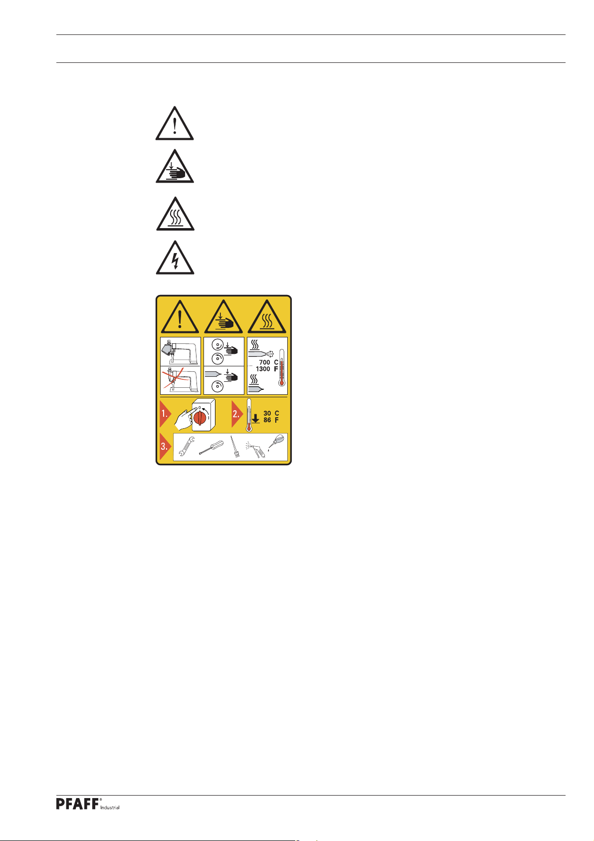
1.03 Safety symbols
Danger!
Special points to observe.
Danger of hands being crushed!
Danger of burns from hot surface!
Danger from electric voltage!
Caution
Do not operate without fi nger guard and safety
devices.
1.04 Important notes for the user
● This instruction manual belongs to the equipment of the machine and must be available
to the operating staff at all times.
● This instruction manual must be read before the machine is operated for the fi rst time.
● Both operating and technical staff must be instructed on the safety devices of the machi-
ne and on safe working methods.
● It is the duty of the user to operate the machine in perfect running order only.
● The user must ensure that none of the safety devices are removed nor put out of wor-
king order.
Turn off the main switch and let the machine cool
down before any setting up, maintenance or cleaning
work!
● The user must ensure that only authorized persons operate and work on the machine.
● The user must make sure there is no high-frequency welding equipment being operated
in direct proximity to the machine that exceeds the EMC limit values according to
EN 60204-31 for the machine.
For further information please refer to your PFAFF agency.
7
Page 8

Safety
1.05 Operating and technical staff
1
1.05.02 Technical staff
.05.01 Operating staff
Operating staff are the persons responsible for setting up, operating and cleaning the machi-
ne and for removing any disturbances in the sewing area.
The operating staff is obliged to observe the following points, and must:
● always observe the notes on safety in this instruction manual!
● avoid using any working methods which adversely affect the safety of the machine!
● avoid wearing loose-fi tting clothing or jewelry such as necklaces or rings!
● also ensure that only authorized persons are allowed near the danger area of the machine!
● immediately report to the user any changes to the machine that may affect its safety!
Technical staff are persons who have been trained in electrical engineering, electronics and
mechanical engineering. They are responsible for lubricating, servicing and repairing the ma-
chine.
The technical staff is obliged to observe the following points, and must:
● always observe the notes on safety in this instruction manual!
● switch off the on/off switch before carrying out any maintenance and repair work on the
machine!
● never work on parts or equipment still connected to the power supply! Exceptions to this
are only permissible according to regulations EN 50110.
● replace all safety covers after maintenance and repair work!
8
Page 9
Safety
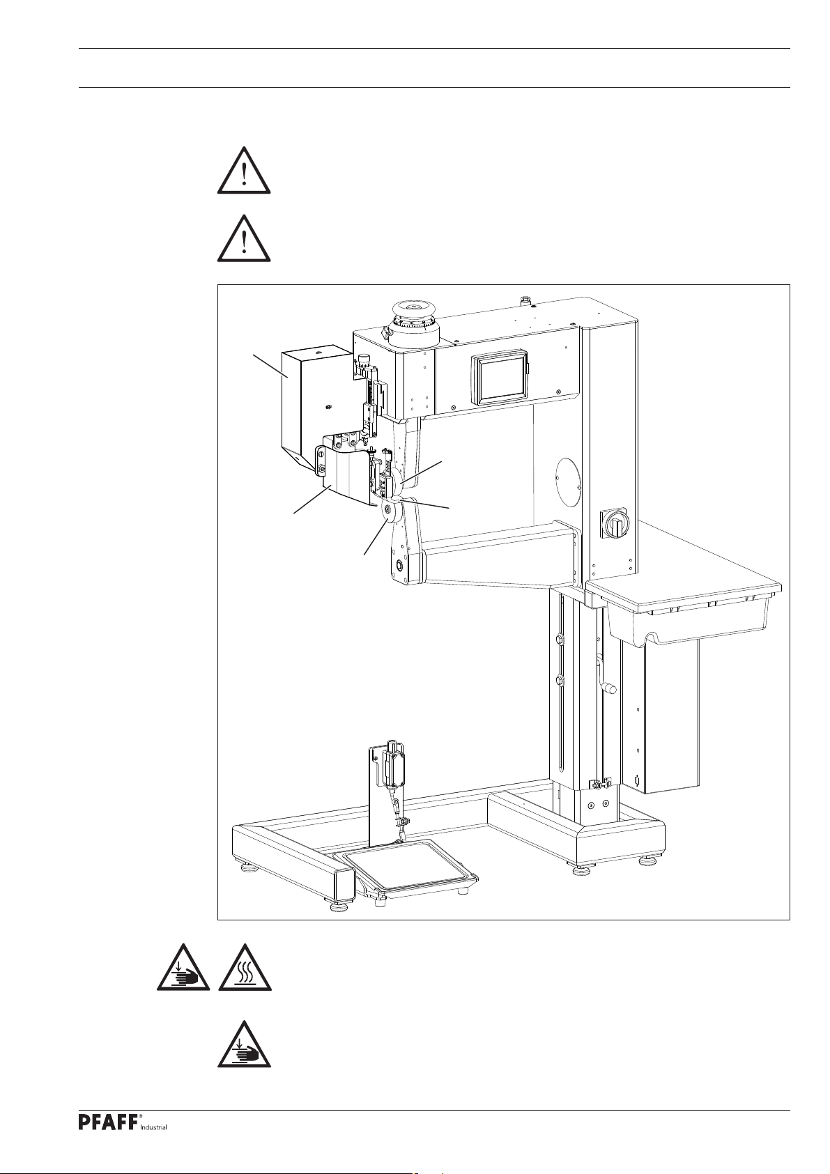
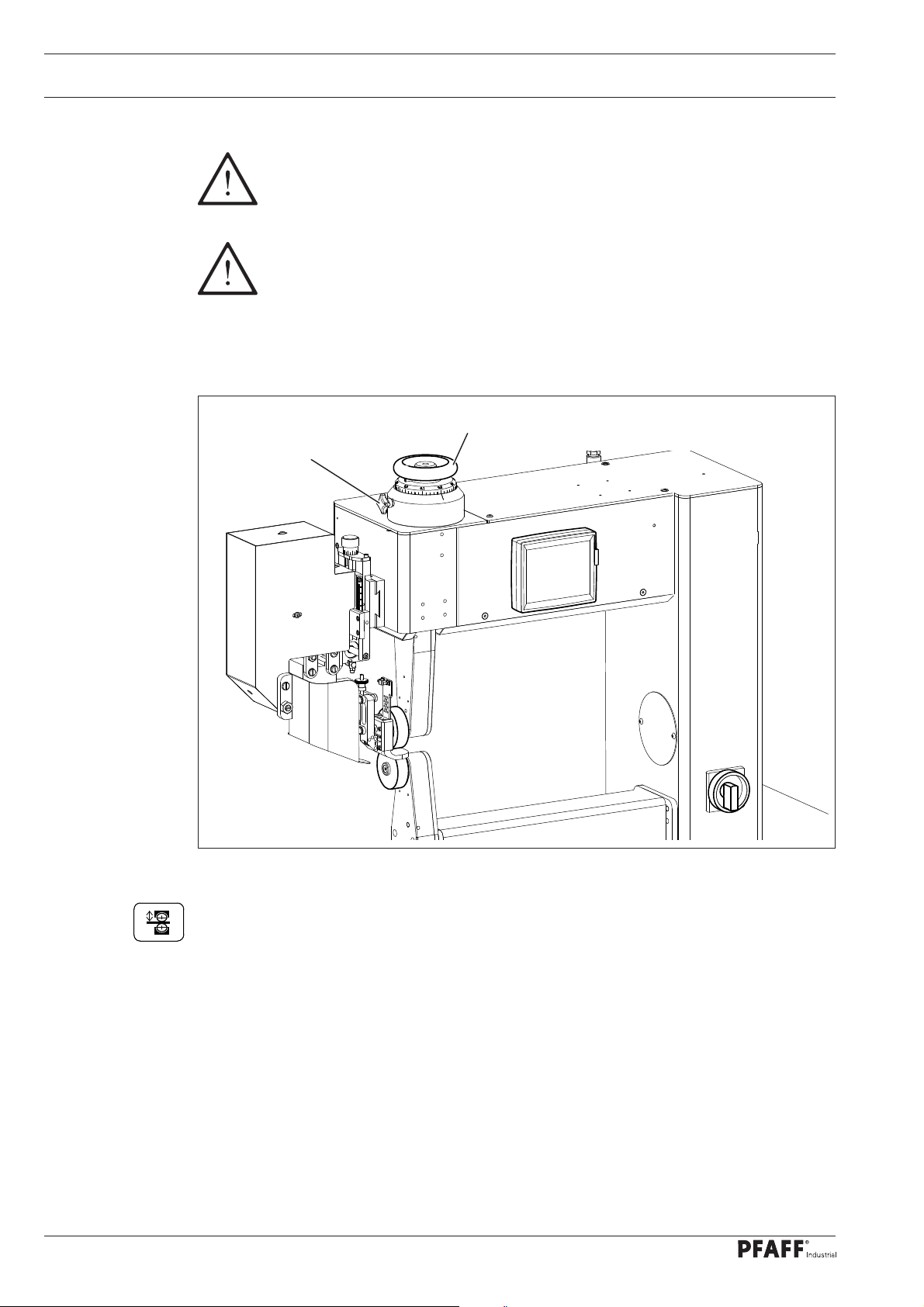
1.06 Danger
When the machine is in operation, a work area of 1 m must be kept free in
front of and behind the machine, so that access to the machine is possible at all
times without diffi culty.
If toxic vapours occur during processing, use extractor!
Danger to health if the toxic vapours are inhaled!
1
4
Fig. 1 - 01
2
3
4
Do not operate the machine without protective cover 1 and only operate the machine with protective cover 2 folded down. Danger of crushing when the heating
element 3 is engaged and disengaged, as well as a danger of burns if touched!
During operation do not place hands near the feed rollers 4!
Danger of crushing if the fi ngers are drawn between the rollers!
9
Page 10

Proper use
2 Proper use
The PFAFF 8320-010 is a hot-wedge sealing machine with swivel post.
The PFAFF 8320-020 is a hot-air sealing machine with swivel post.
The PFAFF 8321-014 is a hot-wedge sealing machine with vertical post.
The PFAFF 8321-024 is a hot-air sealing machine with vertical post.
The machines are used to seal fl exible thermoplastic materials such as e.g. covers, PVC
clothing, insulating and fi lter tubes, small tarpaulins and tents, motorcycle seats etc.
Any and all uses of this machine which have not been approved of by the
manufacturer are considered to be inappropriate! The manufacturer cannot be
held liable for any damage caused by the inappropriate use of the machine!
The appropriate use of the machine includes the observance of all operational,
adjustment, maintenance and repair measures required by the manufacturer!
10
Page 11

Specifi cation
3 Specifi cations▲
Dimensions and weight:
Length: ..................................................................................................................ca. 1100 mm
Width: ..................................................................................................................... ca. 620 mm
Height: ................................................................................................................. ca. 1400 mm
Clearance width: .................................................................................................... ca. 480 mm
Clearance between rollers: ...................................................................................... ca. 20 mm
Net weight: ...............................................................................................................ca. 140 kg
Mains voltage set for: .............................................................230 V ± 10%, 50/60 Hz, 1 phase
Leakage current ........................................................................................................... < 5 mA
Power input
8320-010 (hot-wedge version): ................................................................................ ca. 1500 W
8320-020 (hot-air version): ...................................................................................... ca. 3500 W
◆
Heating capacity
8320-010 (hot-wedge version): ................................................................................ ca. 1500 W
8320-020 (hot-air version): ...................................................................................... ca. 3300 W
Fuse: ..................................................................................................................................16 A
Working air pressure: ................................................................................................. min. 5 bar
Air consumption
8320-010 (hot-wedge version): ..................................................................................... 30 l/min
8320-020 (hot-air version): ..................................................................................30 – 150 l/min
Sealing speed: ............................................................................................... max. 10 m/min.*
Noise data:
Emission sound level at the workplace: .............................................................. LpA<70 dB(A)
(Noise measurement in acc. with DIN 45 635-48-A-1, ISO 11204, ISO 3744, ISO 4871)
Ambient temperature
85% rel. humidity (condensation not permitted): ....................................................... 5 – 40°C
■
Sealing temperature
8320-010 (hot-wedge version): ............................................................................... max. 500°C
8320-020 (hot-air version): ..................................................................................... max. 650°C
▲
Subject to alterations
◆
Due to the use of network fi lters there is a nominal leakage current of < 5 mA.
* Depending on the equipment, up to 30 m/min
■
KpA = 2,5 dB
11
Page 12
Specifi cation
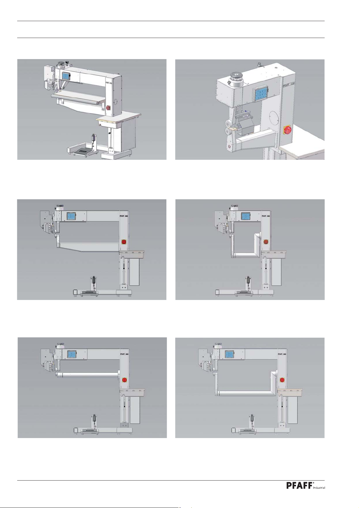
3.01 Machine variants
PFAFF 8320-111
PFAFF 8320-121
PFAFF 8320-111
PFAFF 8320-121
Long-arm version with
table, track rollers and
puller
Long-arm version,
vertical post
PFAFF 8320-011
PFAFF 8320-021
PFAFF 8320-010
PFAFF 8320-020
Standard machine housing,
vertical post, swinging unit
from the right
Standard machine housing,
swivel post
PFAFF 8320-112
PFAFF 8320-122
12
Long-arm version,
cylinder post
PFAFF 8320-110
PFAFF 8320-120
Long-arm version,
swivel post
Page 13
Specifi cation
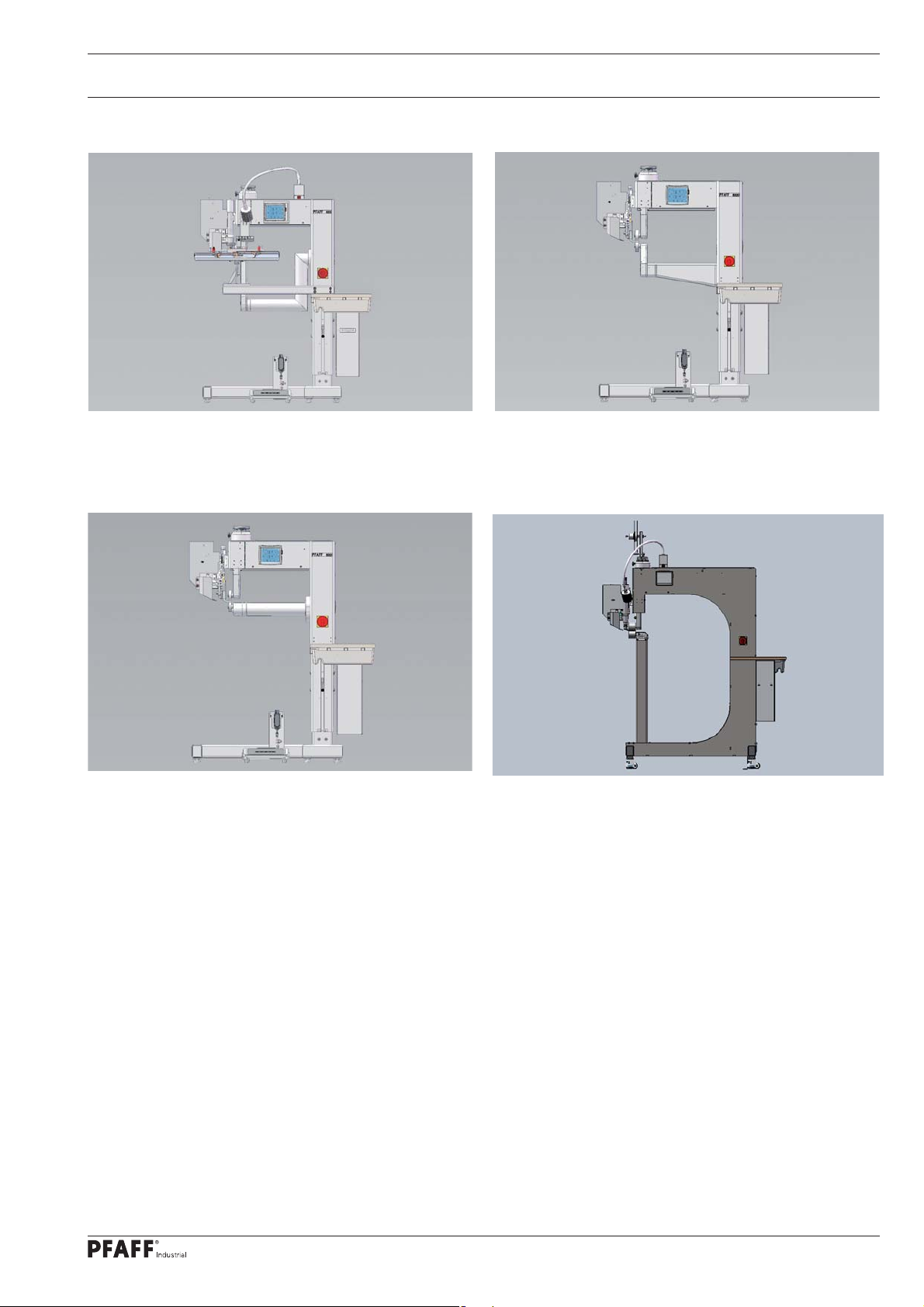
PFAFF 8320-061
PFAFF 8320-061
PFAFF 8320-012
PFAFF 8320-022
Standard machine housing
for fi lter tube production
(hot-air)
Standard machine housing,
cylinder post
PFAFF 8320-011
PFAFF 8320-021
PFAFF 8321-014
PFAFF 8321-024
Standard machine housing,
vertical post
Standard machine housing,
vertical post
13
Page 14

Disposal of Machine
4 Disposal of Machine
● Proper disposal of the machine is the responsibility of the customer.
● The materials used for the machine are steel, aluminium, brass and various plastic
materials. The electrical equipment comprises plastic materials and copper.
● The machine is to be disposed of according to the locally valid pollution control regula-
tions; if necessary, a specialist ist to be commissioned.
Care must be taken that parts soiled with lubricants are disposed of separately
according to the locally valid pollution control regulations!
14
Page 15

Transportation, packing and storage
5 Transportation, packing and storage
.01 Transportation to customer‘s premises
5
The machines are delivered completely packed.
5.02 Transportation inside the customer‘s premises
The manufacturer cannot be made liable for transportation inside the customer‘s premises
nor to other operating locations. It must be ensured that the machines are only transported
in an upright position.
5.03 Disposal of packing materials
The packing materials of this machine comprise paper, cardboard and VCE fi bre. Proper dis-
posal of the packing material is the responsibility of the customer.
5.04 Storage
If the machine is not in use, it can be stored as it is for a period of up to six months, but It
should be protected against dust and moisture.
If the machine is stored for longer periods, the individual parts, especially the surfaces of
moving parts, must be protected against corrosion, e.g. by a fi lm of oil.
15
Page 16

Explanation of symbols
6 Explanation of symbols
In this instruction manual, work to be carried out or important information is accentuated by
symbols. These symbols have the following meanings:
Note, information
Cleaning, care
Lubrication
Maintenance, repairs, adjustment, service work
(only to be carried out by technical staff)
16
Page 17
Controls
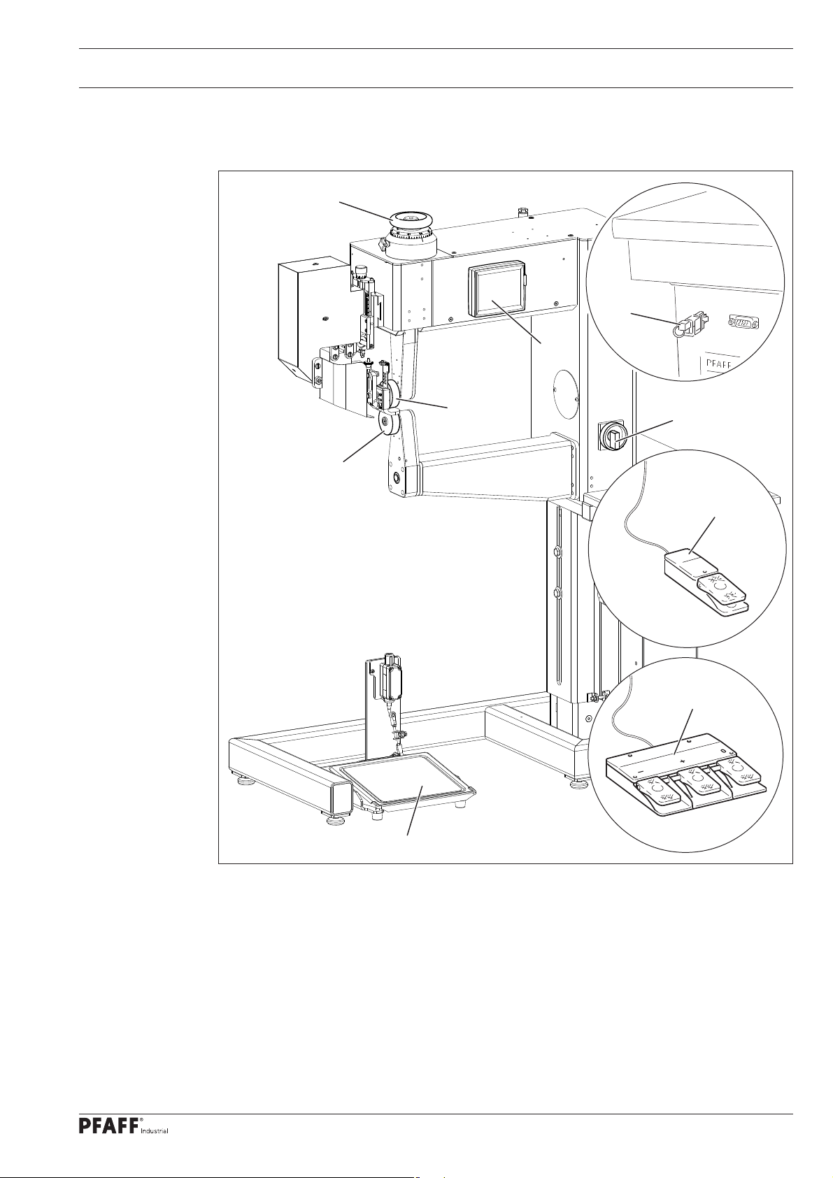
7 Controls
.01 Summary of controls
7
5
9
6
7
1
8
3
4
Fig. 7 - 01
1 Main switch, see Chapter 7.02
2 Pedal, see Chapter 7.03
3 Foot switch (available as an option), see Chapter 7.04
4 Triple foot switch (available as an option), see Chapter 7.05
5 Adjustment wheel for roller clearance, see Chapter 7.06
6 Control panel, see Chapter 7.08
7 Top feed roller
8 Bottom feed roller
9 Key-switch, see Chapter 11.03.02 Rights of access
2
17
Page 18
Controls
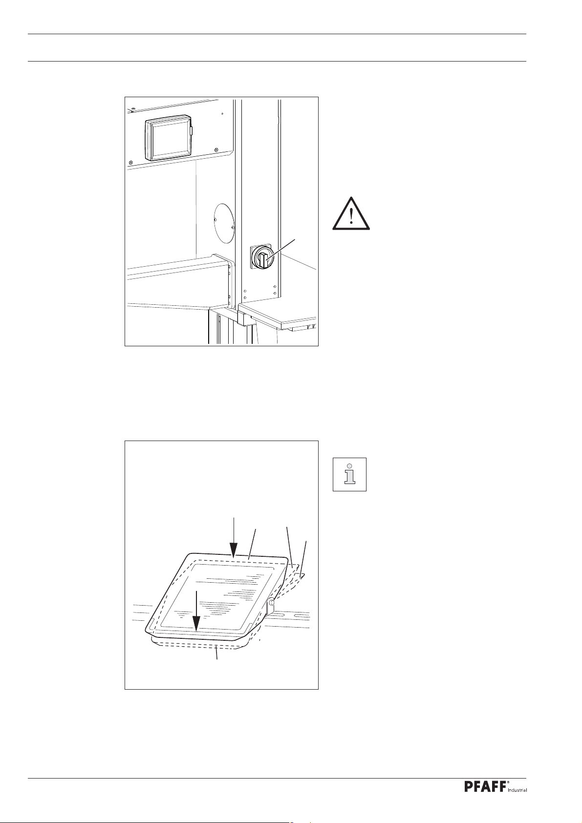
7.02 Main switch
● The machine is switched on or off by
turning main switch 1.
Position "0" : Machine is switched off
Position "1" : Machine is switched on
When switching the
machine on or off, please observe the notes in Chapter 8.03
Switching the machine on and
1
off!
Fig. 7 - 02
7.03 Pedal
The function method of the
pedal depends on the select-
ed pedal mode (level or fl ip-fl op
mode), see Chapter 11.03
Further settings
+1
0
+2
Sealing / level mode
0 = Rest position / Stop sealing process
+1 = Lower top feed roller
+2 = Engage heating element /
Sealing start
-1 = Interrupt sealing process / Raise top
feed roller
18
Fig. 7 - 03
-1
Sealing / fl ip-fl op mode
0 = Rest position
+1 = Lower top feed roller
+2 = Start / Stop sealing
-1 = Interrupt sealing process / Raise top
feed roller
Page 19
Controls
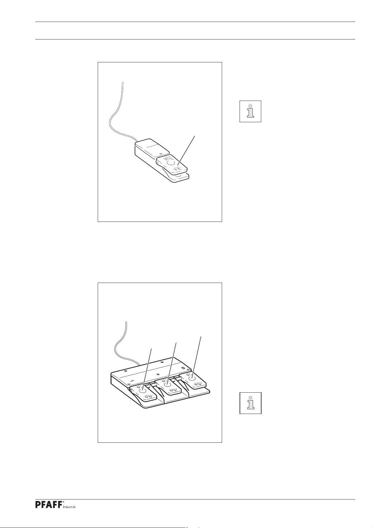
7.04 Foot switch (optional)
● Move to the next sealing section in the
programmed sealing operation by pres-
sing foot switch 1.
Alternatively, a knee switch can
be ordered for this function.
1
Fig. 7 - 04
7.05 Triple foot switch (optional)
1
2
● If the foot switches 1 to 3 are pressed,
the value for the speed difference bet-
ween the top and bottom feed roller is
changed step by step or reset.
1 = Reduce speed of top feed roller
3
step by step
2 = Increase speed of top feed roller
step by step.
3 = Reset speed difference between
the top and bottom feed rollers.
The speed difference between
top and bottom feed rollers is
shown in % on the control
panel.
Fig. 7 - 05
19
Page 20
Controls
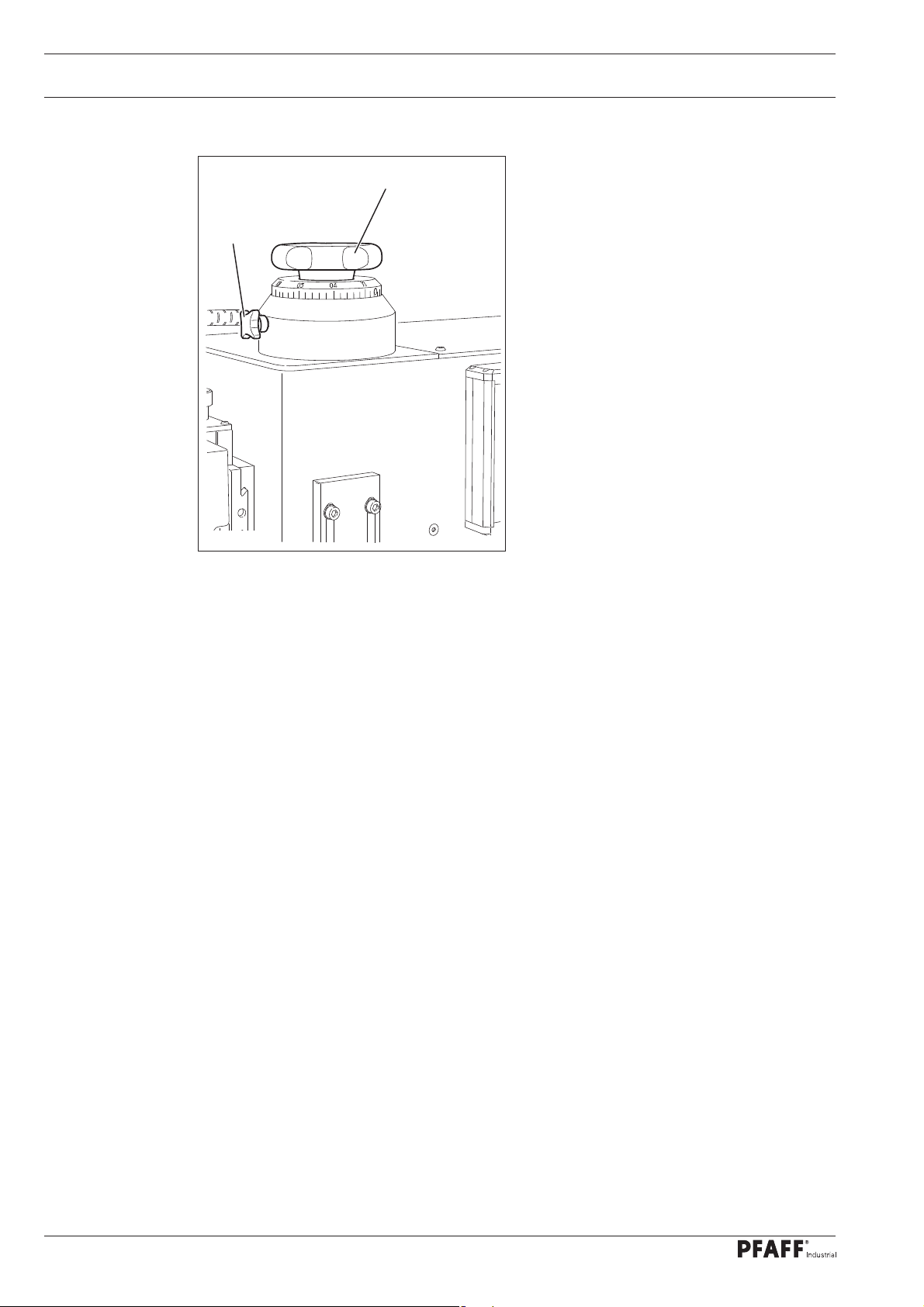
7.06 Adjustment wheel for the roller clearance
● After loosening clamp screw 1, the
2
1
clearance between the top and bottom
feed rollers is changed by turning adjustment wheel 2.
The clearance can be read on the scale.
Fig. 7 - 06
20
Page 21

Controls
7.07 Control panel
1
2 GB
max.
Fig. 7 - 07
The current operating conditions are displayed on control panel 1. Operation takes place in a
constant dialogue between the control unit and the operator. For this purpose, depending on
the operating condition of the machine, different symbols and/or texts are displayed. If the
symbols or texts are framed, these show functions which can be selected by pressing the
appropriate position on the monitor. By pressing the corresponding function this is carried
out or switched on or off immediately, or a further menu appears, e.g. for entering a value.
Activated functions are shown with inverted symbols. Unframed symbols or texts are only
used for display purposes and cannot be selected by pressing.
To read welding programs or install machine software, use the sd-card 2 in the control
panel.
2
Description of the functions
Normal symbol = function switched off (inactive)
Inverted symbol = function switched on (active)
21
Page 22
Installation and commissioning
8 Installation and commissioning
After the machine has been unpacked, check it for any damages caused during transportati-
on. If there are any damages, please notify the transport company and your
local PFAFF agency.
The machine must only be installed and commissioned by qualifi ed personnel.
All relevant safety regulations must be strictly adhered to!
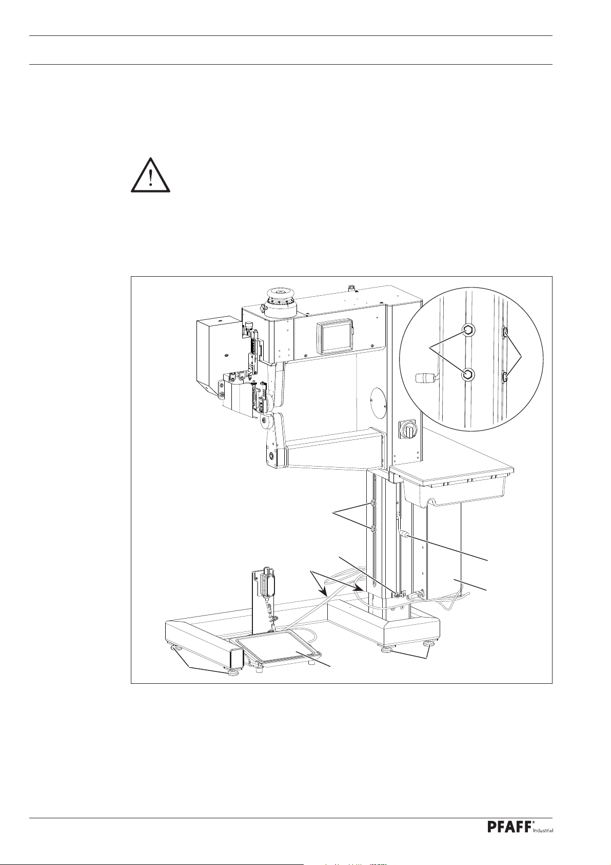
8.01 Installation
Suitable connections for electricity and compressed air must be available at the machine’s
location (see Chapter 3 Specifi cations).
4
4
4
5
1
6
3
22
Fig. 8 - 01
● Slide the machine from the transport pallet.
● Level the machine horizontally by turning the feet 1.
● Connect the plugs from pedal 2 and any existing foot switches to the control box.
● Loosen screws 4 and 5 and adjust the height of the machine by turning crank 6.
● Well tighten screws 4 and 5 again.
1
2
1
Page 23

Installation and commissioning
8.02 Commissioning
● Examine the machine, in particular the electric leads, for any damage.
● Clean the machine thoroughly, also see Chapter 12 Maintenance.
● Connect the machine to the electrical network and have specialists examine, whether the
machine can be operated with the available voltage and whether it is properly connected.
Do not operate the machine if there is any discrepancy!
The machine may only be connected to an earthed socket!
● Connect the machine to the compressed
air system. A pressure of 6 bar should
be displayed on the manometer. If necessary, set this value, see Chapter 12.02
Fig. 8 - 02
0.4 0.6
0.2 0.8
0
+
-
1
1
134-010
Checking / adjusting the air pressure.
The air must be completely oil-
free and dry.
The compressed air quality
influences the service life of the
heating cartridge in the air
heater. If the air is very damp,
a compressed air cold drier with
preliminary filter and secondary
fine filter must be installed in
front of the heat-sealing
machine
23
Page 24
Installation and commissioning
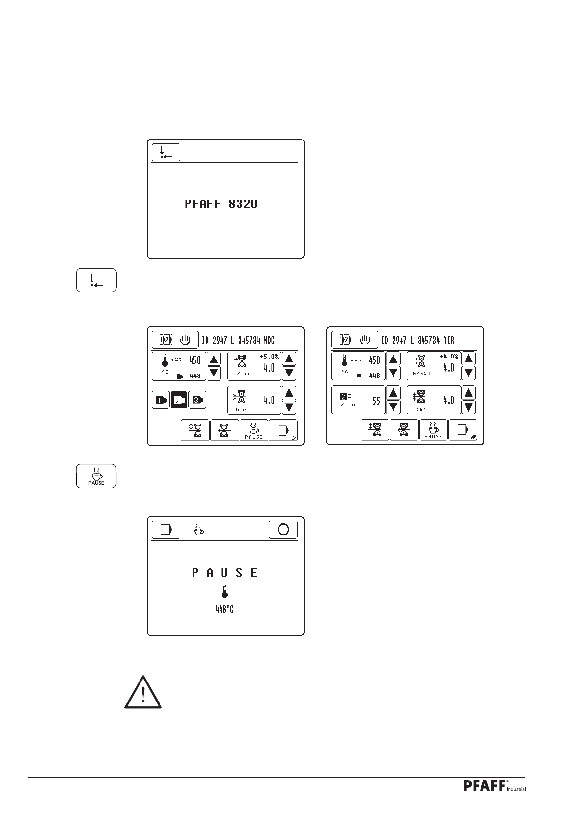
8.03 Switching the machine on/off
● To switch on the machine, turn the main switch to the "I" position, see Chapter 7.02 Main
switch.
● After the boot operation of the control unit, call up the "basic position" function.
PFAFF 8320-010
● To switch off the machine, call up the "pause" function and wait until the blast air
switches off automatically (approx. 1 - 2 min).
PFAFF 8320-020
24
Danger of damage to the heating cartridge!
The hot air temperature must not exceed 100°C when switched off!
Before switching off the compressed air system, wait until the blast air swit-
ches off automatically!
● Turn the main switch to the "0" position, see Chapter 7.02 Main switch.
Page 25
Installation and commissioning
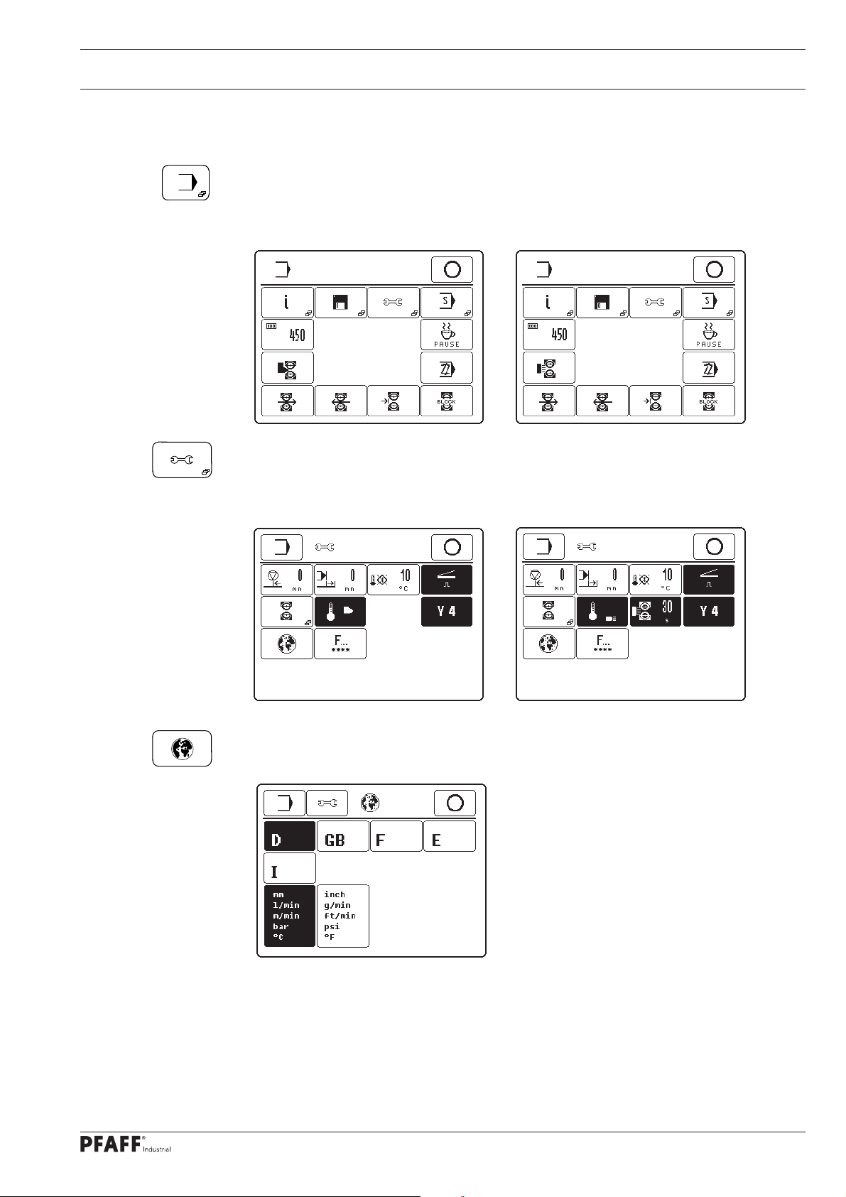
8.04 Selecting the language and units
● Switch on the machine.
● Call up the input menu.
PFAFF 8320-010
● Call up the settings menu.
PFAFF 8320-010
PFAFF 8320-020
PFAFF 8320-020
● Call up the "language setting" menu.
● Select the appropriate language and units.
25
Page 26
Preparation
9 Preparation
9.01 Adjusting the feed roller clearance
All regulations and notes in this Service Manual must be observed!
Special attention must be paid to the safety regulations!
All setting-up work must only be carried out by personnel with the appropriate
training!
2
1
26
Fig. 9 - 01
● Switch on the machine.
● Lower the top feed roller.
● Loosen clamp screw 1.
● Adjust the clearance between the rollers with adjustment wheel 2 depending on the
workpiece and sealing method, see Chapter 7.06 Adjustment wheel for roller
clearance.
● Tighten clamp screw 1.
Page 27
Preparation
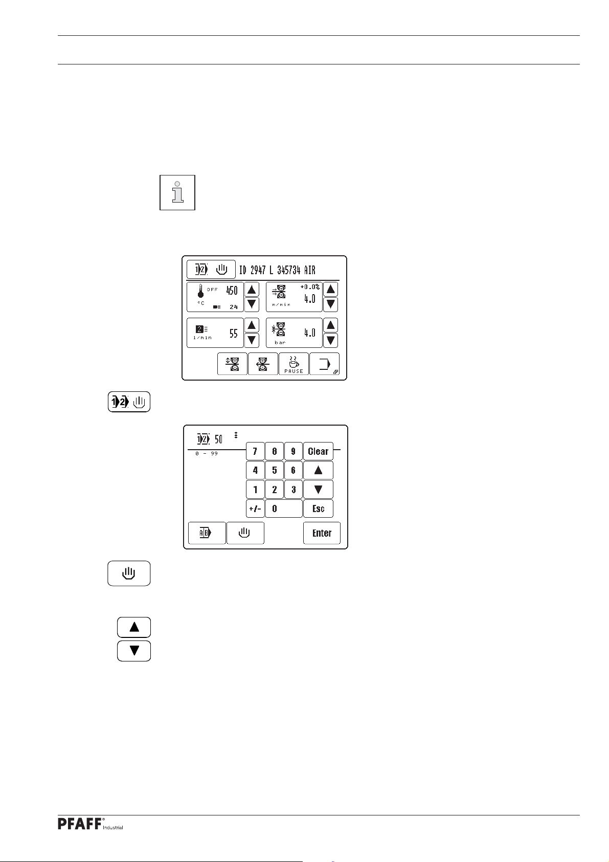
9.02 Selecting the production type:
The program selection function is used to choose between the types of production
- Manual heat sealing (Chapter 10.02)
- Programmed heat sealing with individual programs (Chapter 10.04) and
- Programmed heat sealing with sequences (Chapters 10.06).
The types of production listed above, particularly their functions, are explained
in more detail in Chapter 10 Heat sealing.
● Switch on the machine.
● Call up program selection.
Example 1
● Call up manual heat sealing, the production type, "Manual Heat Sealing" is activated.
or
● Select the desired program number.
(Selection can also be made by entering the program number on the fi gure panel
directly.)
27
Page 28
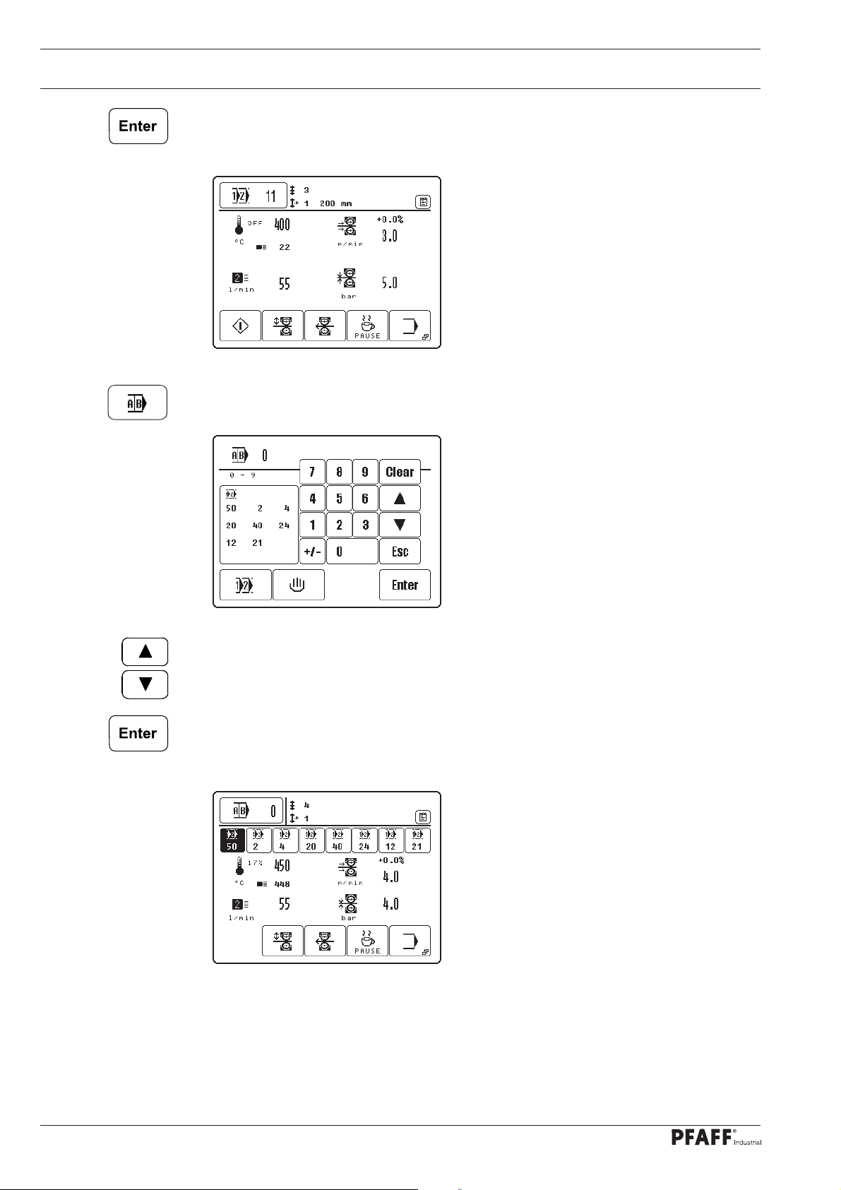
Preparation
● Confi rm selection and quit selection menu, die production type "Programmed Heat
Sealing with individual program" is activated.
Example 2
or
● Call up sequence selection.
● Select desired sequence number.
(Selection can also be made by entering the sequence number on the fi gure panel
directly.)
● Confi rm selection and quit selection menu, die production type "Programmed Heat Seal-
ing with sequence program" is activated.
Example 1
28
Page 29
Preparation
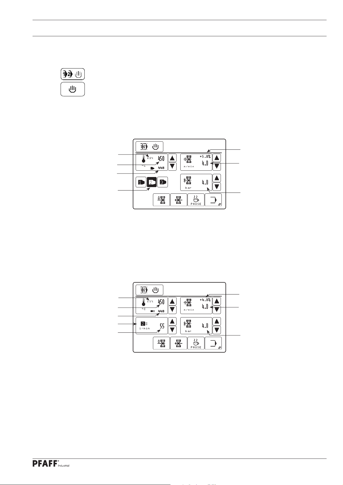
9.03 Entering the sealing parameters (Manual Heat Sealing)
● Switch on the machine.
● Call up program selection.
● Call up manual heat sealing.
PFAFF 8320-010
Duty cycle
Set temperature
Actual temperature
Hot wedge type
Duty cycle
Set temperature
Actual temperature
Nozzle type
Air volume
Comment 20 indications
PFAFF 8320-020
Comment 20 indications
Differential
(top to bottom roller)
Sealing speed
Roller pressure
Differential
(top to bottom roller)
Sealing speed
Roller pressure
29
Page 30

Preparation
After selecting "Manual Heat Sealing", also see Chapter 9.02 Selecting the production
type:, following values can be entered depending on the sealing method:
- Sealing temperature
In addition to the set sealing temperature, the value for the parameter (off = heating off)
appears in the appropriate symbol as well as the actual sealing temperature.
- Sealing speed
In addition to the sealing speed, the value for the difference in speed in % between the
top and bottom feed rollers appears in the appropriate symbol.
- Type of heating wedge or heating nozzle with hot air volume
- Roller pressure
The values can be entered directly by pressing the appropriate key symbol.
In Programmed Heat Sealing the direct input of sealing parameters is not
possible. The alteration must be made in the appropriate sealing program,
see Chapter 10.03 Creating/altering a heat sealing program.
After switching the machine on, after the "pause" function or after detection of
an error, the heating element is switched off (parameter "OFF"). After changing
the sealing temperature, pressing the "start" function or after operating the
pedal, the heating element is switched on again.
30
Page 31

Preparation
9.03.01 Entering the sealing temperature
PFAFF 8320-010
● Increase or reduce the value for the sealing temperature directly.
or
● Call up the fi gure panel to enter the sealing temperature.
__
● Enter the value for the sealing temperature within the permitted range.
● Conclude the input, permissible values will be taken over.
Description of further functions
Clear
● When this function key is pressed, the value is set at "0".
Arrow keys
● When these function keys are pressed, the value is increased or reduced.
Esc
When this function key is pressed, the input is cancelled without the value entered being ta
31
Page 32

Preparation
9.03.02 Entering the sealing speed
PFAFF 8320-020
● Increase or reduce the value for the sealing speed directly.
or
● Call up the fi gure panel to enter the sealing speed.
__
● Enter the value for the speed difference within the permitted range.
● If necessary call up the fi gure panel to enter the speed difference between the top and
bottom feed roller.
32
Page 33

Preparation
__
● Enter the value for the speed difference within the permitted range.
The speed difference results from the change in speed of the top feed roller, which ro-
tates either more quickly or more slowly than the bottom feed roller. The value for the
speed difference depends on the material and application.
● Further sealing parameters
● Select acceleration and brake profi le of the feed rollers, dependent on the material for
sealing. Each of the profi les selected is displayed as an inverse symbol. A fl at ramp
stands for slight acceleration of the feed rollers. The selection of a steep ramp means
high acceleration.
__
● Increase or reduce the start delay for the feed rollers directly.
or
● Call up the fi gure panel to enter the start delay.
Enter the start delay depending on the material being processed.
● Conclude the input, permissible values will be taken over
The start delay function is used to stipulate the amount of time which should
pass between the engaging of the heating element and the start of the feed
rollers.
33
Page 34

Preparation
9.03.03 Stipulating the hot wedge type (only on the PFAFF 8320-010)
● Select the hot wedge type in accordance with the width of the hot wedge installed.
The symbol for the selected hot wedge type appears as an inverse symbol.
Hot wedge
type
1
2
3
Hot wedge version
Heating cartridge with integrated temperature sensor and fast control
response (width 7 mm, 9 mm and 12 mm, 360 W)
Heating cartridge with external temperature sensor and medium control
response (width 15 mm, 20 mm and 30 mm, 500 or 1000 W)
Heating cartridge with external temperature sensor and slow control
response
(width 7 mm, 9 mm and 12 mm, 360 W)
(width > 30 mm, 1000 W)
9.03.04 Adjusting the contact pressure of the hot wedge (only on the PFAFF 8320-010)
● Loosen the locknut 1.
● Adjust the pressure by turning the nut 2
in accordance with the sealing operation,
also see Chapter 13.06.02 Hot wedge
pressure on and clearance to the feed
rollers.
34
● Tighten locknut 1.
1
2
Fig. 9 - 02
Page 35

Preparation
9.03.05 Stipulating the nozzle type and hot air volume (only on the PFAFF 8320-020)
● Increase or reduce the hot air volume directly
or
● Call up input menu to enter hot air volume.
__
● Select the nozzle type in accordance with the width of the nozzle installed.
The symbol for the selected nozzle type appears as an inverse symbol.
Nozzle type Width of nozzle
1 < 10 mm
2 10 mm - 30 mm
3 > 30 mm
● Using the number block, enter the value for the hot air volume within the permitted
range.
● Conclude the input, permissible values will be taken over.
Description of further functions
Clear
● When this function key is pressed, the value is set at "0".
Arrow keys
● When these function keys are pressed, the value is increased or reduced.
Esc
When this function key is pressed, the input is cancelled without the value entered being
taken over.
35
Page 36

Preparation
9.03.06 Entering the roller pressure
PFAFF 8320-010
● Increase or reduce the roller pressure directly.
or
● Call up the number panel to enter the roller pressure.
__
● Enter the roller pressure within the permitted range
● Conclude the input, permissible values will be taken over.
Roller pressure can be capped for specifi c application cases
(see chapter 11.03.01)
36
Page 37

Preparation
9.04 Adjusting the control panel
● Switch on the machine.
● Call up the input mode.
PFAFF 8320-010
● Select the service menu.
PFAFF 8320-020
● Select control panel functions.
● Switch the key tone off or on.
● Change the display contrast. (Function only on the control panel BDF T1).
Never reduce the display contrast to the extent, that the display can no
longer be read!
37
Page 38

Heat sealing
10 Heat sealing
The machine may only be operated by properly instructed personnel. The oper-
ating personnel must make sure that only authorised persons are in the danger
zone of the machine.
In particular for production, in addition to the input menu (see Chapter 11 Input), the „heat
sealing“ mode is available, in which, irrespective of the program selected and the machine
status, all functions and settings relevant for the sealing operation are shown on the display.
With the program selection function, following production types can be selected in the "heat
sealing" mode, see Chapter 9.02 Selecting the production type:
Manual heat sealing, see Chapter 10.02
Programmed heat sealing with individual programs, see Chapter 10.04
Programmed heat sealing with sequences, see Chapter 10.06
10.01 Heat sealing principle
To achieve optimum sealing results, certain conditions must be fulfi lled with regard to mate-
rial and machine setting.
The material must:
- be heat-sealable, and
- suitable for being processed by the machine with regard to thickness and structure.
In the seam area, the material to be heat sealed must be clean and free from separating
agents, such as e.g. oil or silicone.
The basic conditions depending on the sealing device are:
- correct working temperature of the hot wedge or hot air temperature (sealing temperature);
- correct contact pressure of the hot wedge and the correct position of the hot air nozzle;
- correct setting for the hot air volume;
- correct choice of feed rollers (silicone or steel);
- optimum pressure of the feed rollers on the material being sealed (roller pressure);
- correct distance between the feed rollers and
- correct sealing speed (feed stroke).
All the settings of the heat-sealing device are principally dependent on the ma-
terial being sealed and the ambient temperature. Due to the infl uence of the in-
dividual operating parameter on each other, it is only possible to determine the
optimum setting values by carrying out test sealing operations.
38
Page 39

Heat sealing
10.02 Manual heat sealing
In the "Manual heat sealing" mode, all relevant parameters for the sealing operation can be
entered or altered directly, see Chapter 9.02 Selecting the production type.
● Select "manual heat sealing", see Chapter 9.02 Selecting the production type
PFAFF 8320-010
Description of the functions
Selecting a program
This function opens the menu for entering the program number or for selecting the production type, see Chapter 9.02 Selecting the production type
Comment Field
This function opens the menu to allow the input of a comment (max. 20 chars.), e.g. material
assignment for the selected welding parameters.
PFAFF 8320-020
Heat sealing temperature
These functions are used to alter the heat sealing temperature, see Chapter 9.03.01
Entering the sealing temperature.
Feed stroke (sealing speed)
These functions are used to alter the feed stroke or to open the menu for entering the feed
stroke difference, the brake and acceleration profi les and the start delay for the feed rollers,
see Chapter 9.03.02 Entering the sealing speed.
Hot wedge type (only on the PFAFF 8320-010)
These functions are used to stipulate the hot wedge type, see Chapter 9.03.03 Stipulating
the hot wedge type… The selected function appears inverse.
Nozzle type / hot air volume (only on the PFAFF 8320-020)
These functions are used to alter the hot air volume or to open the menu for stipulating the
nozzle type, see Chapter 9.03.05 Stipulating the nozzle type and hot air volume …
Roller pressure
These functions are used to alter the roller pressure, see Chapter 9.03.06 Entering the roller pressure.
39
Page 40

Heat sealing
Start
(This function appears when the top feed roller is lowered.)
With this function the sealing start is called up, analog to the pedal function "+2", also see
Chapter 7.04 Pedal.
Feed roller up/down
With this function the top feed roller, depending on its position, can be raised or lowered,
analog to the pedal functions "-1" and "+1", also see Chapter 7.04 Pedal.
Feed rollers in reverse
This function makes it possible to call up the reverse running function of the feed rollers.
Break
This function is used to switch off the temperature control of the heating element.
The heating element cools down.
Input menu
This function is used to call up the "input" mode, see Chapter 11 Input.
Stop
(This function appears during the sealing operation.)
This function is used to stop the sealing operation, analog to pedal function "-1", also see
Chapter 7.04 Pedal.
During the sealing process, the machine is operated by pedal and foot switch,
see Chapter 7 Controls.
40
Page 41

Heat sealing
10.03 Creating/editing a heat sealing program
Up to 100 sealing programs (0 – 99) each with up to 20 sealing zones can be fi led and man-
aged in the machine memory.
● Call up the input menu.
● With the “programming” function from the input menu it is possible to enter the pro-
gramming function for sealing programs. A number block for entering the desired pro-
gram number appears.
Creating a new program
Altering a program
Example 1
If no program is fi led in the memory under the program number selected, the current seal-
ing parameter of the manual heat sealing function will be taken over and a new program cre-
ated.
As an alternative to the creation of a new program, the program number of an existing program (e.g. 10) can be selected, and this program can be changed or copied to create a new
program. In the case of existing programs, the number of zones and possibly a comment are
displayed next to the program number in the headline.
● Enter the program number, e.g. "10".
● Confi rm selection.
Example 1
The fi rst zone of the selected program is displayed on the screen with functions for enter-
ing sealing parameters, notes, switching to the next zone, as well as basic functions for the
program input. For further descriptions of the functions see Chapter 10.03.07 Example for
sealing program input.
41
Page 42

Heat sealing
10.03.01 Notepad
When creating a sealing program, this function is used to enter data about the sealing tools
for the program. The data serves as information for the operator and can be called up in the
programmed sealing mode.
● Press the relevant key panels to enter the data.
● Enter the relevant data.
● Conclude the input
42
Page 43

Heat sealing
10.03.02 Basic functions for the program input
The following functions are used to enter the basic information for the currently selected
program. In addition to functions for navigating in the different zones and functions for in-
serting and deleting zones, depending on the zone displayed, functions can be called up for
entering further parameters and comments as well as for concluding the program input.
● Call up the appropriate functions to process or conclude the program.
Description of the functions
Selecting a zone
These functions are used to switch forwards and backwards to other zones in the current
program.
Insert
This function inserts a new zone at the current location. The data of the current zone are
copied for the new zone and the following zones are moved one place back.
Delete
This function deletes the current zone.
Further sealing parameters
(This function only appears in the fi rst zone.)
This function opens a menu for entering further sealing parameters, for example, nozzle or
hot wedge type, see also Chapter 10.03.05 Further sealing parameters.
Comment
(This function only appears in the fi rst zone.)
With this function, when entering a note, see Chapter 10.03.01 Notepad, the analog entry
of a comment about the current program is possible. The comment is displayed as informa-
tion about the appropriate program in the program selection and program management func-
tions.
Add
(This function only appears in the last zone.)
This function is used to copy the data of the current zone and add it as a new zone.
Conclude programming
This function concludes the programming, see Chapter 10.03.06 Concluding the program-
ming.
43
Page 44

Heat sealing
10.03.03 Sealing parameters
● Enter sealing parameters for each zone as described in Chapter 9.03 Entering sealing
parameters (manual heat sealing).
Description of the functions
Heat sealing temperature
This function is used to alter the heat sealing temperature, see Chapter 9.03.01 Entering
the sealing temperature.
Feed stroke (sealing speed)
This function is used to open the menu for entering the feed stroke difference, the brake and
acceleration profi les and the start delay for the feed rollers, see Chapter 9.03.02 Entering
the sealing speed.
Roller pressure
This function is used to alter the roller pressure, see Chapter 9.03.04 Entering the roller
pressure.
Hot air volume (nur bei der PFAFF 8320-020
This function is used to alter the hot air volume.
44
Page 45

Heat sealing
10.03.04 Functions for switching to other zones
In addition to the sealing parameters, further functions can be allocated to each zone, which
serve to enable the automatic switch to other zones and a more exact setting of the sealing
operation sequence.
● Select appropriate functions for each zone, activated functions are displayed as inverse
symbols on the screen.
Description of the functions
Programmed section
mm
This function is used to determine the length of the current zone. The value in millimetres
is entered on the appropriate number block. When this function is activated, the machine
switches to the next sealing zone after processing the entered section.
Loop program command
When this function is switched on a loop is programmed into the program sequence.
Entering the return target position
Here, the number of a previous zone can be entered.
Entering the number of loop iterations 0 - 99
Input "0" = the loop runs endlessly
IN2
Programmed output
When this function is switched on, the current zone takes on an output switch function. Two
outputs can be stipulated with the appropriate menu. The sealing parameters entered for
this zone are not taken into account.
Programmed input
When this function is switched on, the machine does not switch to another zone until an
appropriate input signal is given or not given. The two different inputs can be set up with the
appropriate menu.
Sealing on/off
When this function is switched on, the current zone takes on a switching function. The seal-
ing operation is switched off or on and the machine moves to the next zone. For the follow-
ing zones, the sealing remains switched off or on until the setting is changed again.
Interrupt the loop with a high level (24V) on free input IN2 (X8/PIN3)
Zone forwarding with foot switch 1 at Stop (see chapter 7.04) skips the loop
command
Programmed Stop
Activating this function will transform the current range to a stop function. The welding
stop is executed and a transfer to the next range occurs. The welding parameters entered for that range will not be applied.
45
Page 46

Heat sealing
10.03.05 Entering further sealing parameters
Further sealing parameters can be entered either
● from the manual resp. dynamic sealing mode in conjunction with the sealing speed input
or
● when creating programs in conjunction with the input of the fi rst zone.
Input while
creating programs
with PFAFF 8320-010
Example
Example
● Select acceleration and brake profi le of the feed rollers, dependent on the material for
sealing. Each of the profi les selected is displayed as an inverse symbol. A fl at ramp
stands for slight acceleration of the feed rollers. The selection of a steep ramp means
high acceleration.
If the sealing result is unsatisfactory, the alteration of the acceleration or brake
profi le can lead to an improvement.
The values of the different acceleration and brake profi les can be stipulated in
the input mode, see Chapter 11.03.01 Feed roller parameters.
Input while
creating programs
with PFAFF 8320-020
46
__
● Increase or reduce the start delay for the feed rollers directly.
or
● Call up the fi gure panel to enter the start delay.
Enter the start delay depending on the material being processed.
● Conclude the input, permissible values will be taken over
The start delay function is used to stipulate the amount of time which should
pass between the engaging of the heating element and the start of the feed
rollers.
Page 47

Heat sealing
Further functions are available for creating programs:
● Select the sealing tool by switching between heating wedge and hot air nozzle. This
makes it possible e.g. to also create programs for hot air machines on hot wedge machi-
nes.
● Select the nozzle type in accordance with the width of the nozzle installed, see Chapter
9.03.05 Stipulating the nozzle type and hot air volume …
or
● Select the hot wedge type in accordance with the width of the hot wedge installed, see
Chapter 9.03.03 Stipulating the hot wedge type …
10.03.06 Concluding programming
Once all the details for the programming have been entered, the programming can be
concluded by pressing the appropriate function key.
Example
Example
Description of the functions
Esc
The input is interrupted and the machine moves back to the initial state of the programming
function.
Discard alterations
All program alterations are cancelled.
Save as...
If this function key is pressed, the number panel opens to enter any program number.
Enter
All program alterations are saved under the current program number.
47
Page 48

Heat sealing
10.03.07 Example of how to enter a sealing program
The following example should be fi led under program number "10" with the comment "example 1", and consists of three seam zones:
1. Seam zone 1 with switch to another zone after 200 mm seam length
- 2. Seam zone with reduced welding speed and speed difference between the upper and
lower transport roller and with zone forwarding after 100 mm
- 3. Seam zone back to original welding speed without speed difference between transport rollers and with zone forwarding after 400 mm
● Switch on the machine.
● Call up the programming function..
● Enter program number "10".
● Confi rm input.
The sealing parameters from the manual sewing mode are taken over for seam zone 1.
48
Page 49

Heat sealing
● Call up comment input.
● Enter the term "example" with the appropriate symbols.
● Change to number input.
Example
● Enter number "1" with the appropriate symbol.
● Conclude the comment input.
Example 1
mm
● Activate the switch to another zone using the seam length.
● Enter the value "200" as seam length with the number panel.
● Conclude the activated function for switching to another zone.
49
Page 50

Heat sealing
Example 1
● Add seam zone 2.
Example 1
● Change the values for sealing speed and speed difference.
● Activate the switch to another zone with the value "100" as seam length.
mm
Example 1
● Conclude the input of seam zone 2.
Example 1
50
Page 51

Heat sealing
● Add seam zone 3.
● Reset the values for sealing speed and speed difference.
mm
● Activate the switch to another zone with the value "400" as seam length.
● Conclude the input of seam zone 3.
Example 1
● Conclude programming.
Example 1
● Reconfi rm the sealing program input.
The programmed sealing function is called up to process the created sealing program.
Example 1
4
The entered program is automatically activated.
51
Page 52

Heat sealing
10.04 Programmed heat sealing with individual programs
In the headline, in addition to the program number of the selected program, the number
of zones, the current zone and the comment for the program are displayed. For the current
zone all heat-sealing parameters are displayed. The heat-sealing parameters have been
stipulated during programming and cannot be processed without changing the program.
● Select the desired program, see Chapter 9.02 Selecting the production type.
PFAFF 8320-010
Example 1
Description of the functions
Program selection
The function opens the menu for entering the program number or for choosing the
production type, see Chapter 9.02 Selecting the production type.
Notepad
This function opens the notepad with program details about the heat-sealing tools
to be used.
Start
(This function appears, when the top feed roller is lowered.)
This function is used to call up the sealing start, analog to pedal function "+2", also see
Chapter 7.03 Pedal.
PFAFF 8320-020
Example 2
52
Feed roller up/down
This function is use to raise or lower the top feed roller, depending on its position, analog to
the pedal functions "-1" and "+1", also, see Chapter 7.03 Pedal
Feed rollers in reverse
This function can be used to call up the reverse running function of the feed rollers
Break
This function is used to switch off the temperature control of the heating element.
The heating element cools down.
Input menu
This function is used to call up the "Input" mode, see Chapter 11 Input.
Stop
(This function appears during the heat-sealing operation.)
This function is used to stop the heat-sealing operation, analog to pedal function "-1", also
see Chapter 7.03 Pedal
Page 53

Heat sealing
10.05 Creating/processing sequences
In sequences up to 8 heat sealing programs are combined in any order whatever and fi led
under a sequence number. A total of up to 10 sequence programs can be fi led in the ma-
chine’s memory.
● To enter sequence programming, fi rst of all call up the Program selection function.
● Call up the Sequence selection function and select the desired sequence number.
● Call up sequence programming.
The cursor in the window shows which program is being deleted or at which point
a new program is being inserted.
Description of the functions
Arrow keys
These functions are used to move the cursor.
Insert
This function inserts or adds a program to the sequence at the place marked.
Delete
This function deletes the marked program from the sequence.
Conclude programming
This function concludes the sequence programming.
53
Page 54

Heat sealing
10.06 Programmed heat sealing with sequences
In the headline, in addition to the sequence number of the selected sequence, the num-
ber of zones, the current zone and the comment for the current program are displayed. For
the current zone all heat-sealing parameters are displayed. The heat-sealing parameters have
been stipulated during programming and cannot be processed without changing the pro-
gram. In addition, in the case of heat sealing with sequence programs, the individual pro-
grams belonging to the sequence are displayed, and the current program is shown here as
an inverse symbol.
● Select the desired sequence, see Chapter 9.02 Selecting the production type.
Example 1
Description of the functions
Program selection
The function opens the menu for entering the program number or for choosing the
production type, see Chapter 9.02 Selecting the production type.
Notepad
This function opens the notepad with program details about the heat-sealing tools
to be used.
Heat sealing program
Press this function to select the appropriate heat sealing program.
Start
(This function appears, when the top feed roller is lowered.)
This function is used to call up the sealing start, analog to pedal function "+2", also see
Chapter 7.03 Pedal.
Feed roller up/down
This function is use to raise or lower the top feed roller, depending on its position, analog to
the pedal functions "-1" and "+1", also, see Chapter 7.03 Pedal
Feed rollers in reverse
This function can be used to call up the reverse running function of the feed rollers.
54
Break
This function is used to switch off the temperature control of the heating element.
The heating element cools down.
Input menu
This function is used to call up the "Input" mode, see Chapter 11 Input.
Page 55

Heat sealing
Stop
(This function appears during the heat-sealing operation.)
This function is used to stop the heat-sealing operation, analog to pedal function "-1", also
see Chapter 7.03 Pedal.
Sequence programs are run as follows depending on the parameter setting
'Sequence continue':
Sequence continue = 1
The programs are executed in sequence according to the sequence
displayed. The currently executing program is shown inversely.
The sequence can be restarted at any point by pressing one of the program
buttons.
Sequence continue = 0
The selected program remains selected and is shown inversely. A different
program can be selected at any time by pressing one of the program buttons
(quick key selection).
55
Page 56

Heat sealing
10.07 Error messages
In case of a malfunction, an error code appears on the display. An error message may be
caused by incorrect handling, faults on the machine or by overload conditions.
For the explanation of the error code, see Chapter 13.13 Explanation of the
error numbers.
● Eliminate the error..
● Acknowledge the elimination of the error.
or
● Call up the input menu to eliminate the error with the service functions.
56
Page 57

Input
11 Input
Contained in the input mode are the functions for displaying information, for program ma-
nagement, for machine adjustment and confi guration (incl. choice of country and access
rights), as well as for supporting service and adjustment work.
11.01 Summary of the functions in the input mode
● Switch on the machine.
● Call up the input mode
PFAFF 8320-010
Description of the functions
Heat sealing mode
This function is used to change to the heat sealing mode.
Info
This function opens a menu to display the following information:
- Current software status of the machine
- Current fi rmware status of the machine
- Current fi rmware status of the control panel
- Regulation degree of the temperature control unit
- Number of operating hours (can be reset with the Clear function)
- Number of production hours (can be reset with the Clear function)
PFAFF 8320-020
Program management
This function is used to manage the data from the machine memory and disks,
see Chapter 11.02 Program management.
Further settings
This function is used to call up a menu for stipulating further machine settings,
the choice of country and the access rights, see Chapter 11.03 Further settings.
Service menu
This function is used to call up the menu for selecting various service functions,
see Chapter 13.11 Service menu.
57
Page 58

Input
450
Daily piece counter
This function is used to call up the daily piece counter. The daily piece counter can be reset
with the Clear function.
Break
This function is used to switch off the temperature control of the heating element.
The heating element cools down.
Grinding the hot wedge (only on the PFAFF 8320-010)
After this function has been called up, the hot wedge can be ground. The speed of the feed
rollers can be altered in the menu displayed. The grinding operation is controlled with the pedal function, see Chapter 12.05 Grinding the hot wedge…
Pre-heating the feed rollers (only on the PFAFF 8320-020)
This function is used to switch the manual pre-heating function of the feed rollers on or off.
When the function is activated, a menu opens for entering the pre-heating time.
Programming
These functions are used to enter the Creating or Altering Heat-Sealing Programs, see
Chapter 10.03 Creating/altering heat sealing programs.
Feed rollers forwards/backwards
This function makes it possible to turn the feed rollers forwards/backwards at a freely
selectable speed. For this purpose a menu is opened with functions for selecting the
speed of the feed rollers and rotational direction, as well as for stopping and starting
the feed rollers.
Positioning the heating element
With the use of this function, the heating element can be engaged manually to facilitate the
positioning of the heating element to the feed rollers. A menu is opened with functions for
carry out the engaging or disengaging operation.
Locking the feed rollers
This function is used to lock the feed rollers in order to facilitate a feed roller change. A menu
is opened with a function for releasing the lock again.
58
Page 59

Input
11.02 Program management
The program management function is used to manage sealing programs as well as confi gu-
ration and machine data. Files can be selected from the machine memory or from a disk and
be copied or deleted.
● Switch on the machine.
● Call up the input mode.
● Call up the program management function
If the machine is equipped with a
Floppy Disk drive, the operator can
switch between Floppy and SD-
Card with the button.
The directoryies of machine memory and SD-Card appear on the display:
- Left window: Machine memory ("C:\DATEN\" - is currently selected)
- Right window: SD-Card
The medium is selected by touching the appropriate fi eld. The selected medium and the se-
lected fi les are shown as inverse symbols:
Sealing programs are fi led at a different level to that for the confi guration and
machine data, in order to avoid the confi guration and machine data being pro-
cessed by mistake.
Description of the functions
Input menu
This function is used to call up the input menu.
Refresh directoryies
This function is used to refresh the directoryies of machine memory and SD-Card.
Sealing mode
This function is used to change to the sealing mode.
Data selection
With these functions the desired fi les are marked in the current drive. Individual fi les are se-
lected with the arrow keys. In combination with the Lock key (*) several fi les can be selected
at one time with the arrow keys.
Copy
This function is used to copy the selected fi les from the current storage medium onto the
second storage medium.
59
Page 60

Input
Delete
This function is used to delete the selected fi les.
MDAT/KONF
This function is used to call up the level for the confi guration and machine data. The
current settings and the machine confi guration are stored in the fi les „MDAT8320“ and
„KONF8320.BIN“. In this way the machine data can be copied on to a disk as a backup, or
several machines with the same designation can be confi gured quickly by reading the
machine data.
Format
This function is used to format the fl oppy disk inserted. In case of SD-Card, a folder P8320 is
created
In the course of the formatting operation, all data on the disk are deleted!
On SD-Card, only the contend of folder P8320 is deleted!
60
Page 61

Input
11.03 Further settings
The further settings are use for stipulating further machine settings, the choice of country
and access rights.
● Switch on the machine.
● Call up the input mode.
● Call up the input menu for further settings.
PFAFF 8320-010
Description of the functions
Input menu
This function is used to call up the input menu.
Sealing mode
This function is used to change to the sealing mode.
Feed unit backwards after stop
This function is used to enter the distance which the feed unit should move back after a
sealing stop.
PFAFF 8320-020
Feed unit forwards at end
The function can be switched on or off. When the function is switched on, the distance,
which the feed unit should continue moving after the end of sealing, can be entered.
Temperature window for sealing start
This function is used to enter the tolerance between the actual and the set temperature,
within which a sealing start is possible. If the actual temperature is outside the tolerance ,
the sealing start is blocked.
Flip-fl op mode (pedal)
This function is used to switch the fl ip-fl op mode for the pedal function on or off:
- Function switched on (symbol shown inverse)
The pedal function is only carried out as long as the pedal is held in the appropriate
position.
- Function switched off
The pedal function is carried out as soon as the pedal is brought into the appropriate posi-
tion and remains active after the pedal has been released.
61
Page 62

Input
Feed roller parameters
This function opens a menu for entering the feed roller parameters, see Chapter 11.03.01
Feed roller parameters.
Automatic heat-up
This function switches the automatic heat-up function on or off. With the function activated,
the heating element is slowly heated in a range between 20° and 120° to prevent damage to
the element due to abrupt temperature change.
Pre-heating the feed rollers (only on the PFAFF 8320-020)
##
30
s
This function is used to switch the automatic pre-heating function of the feed rollers on or
off. When the function is activated, a menu opens for entering the pre-heating time.
Country settings
This function opens a menu for setting the language and measuring units for each country.,
see Chapter 8.04 Selecting the language and units.
Right of access
This function calls up the menu for defi ning access rights, see Chapter 11.03.02 Rights of
access.
Swivel sequence of the heating element
This function is used to switch the "Y4" valve for engaging and disengaging the heating element on or off. The "Y4" valve controls the cylinder for moving the heating element back-
wards and forwards.
When the function is switched on (standard) the heating element is engaged and disen-
gaged in two steps:
1. Engage or disengage heating element crosswise to the feed rollers.
2. Engage or disengage heating element in the sealing direction.
When the function is switched off, step 2 is not carried out, the heating element is always in
the forward position.
62
Page 63

Input
11 .03.01 Feed roller parameters
In this menu the relevant parameters for the feed rollers are preset.
● Switch on the machine.
● Enter the input mode.
● Call up further settings.
● Call up the menu for entering the feed roller parameters.
Description of the functions
Input menu
This function is used to change from the initial state to the input mode.
Further settings
This function calls up the menu for entering further settings again.
Sealing mode
This function is used to change to the sealing mode.
Acceleration and brake profi les
This function is used to enter the values for the corresponding acceleration or brake profi les.
Feed roller pressure limit
#.#
6.0
bar
This function is used to enter the maximum permissible value for the feed roller pressure.
Basic position of the top feed roller
This function is used to select the basic position of the top feed roller. The basic position of
the feed roller can be raised or lowered.
Feed difference inkrement
#.#
0.2
%
This function is used to enter the inkrement of the feed difference,
see chapter. 7.05 Triple foot switch.
63
Page 64

Input
11 .03.02 Rights of access
The functions, which can be called up with the control panel, are classifi ed by code numbers
and can be protected from unauthorised access. For this purpose, the control unit differentiates between 3 user groups (user 1, 2 and 3), all of which can be assigned a corresponding
PIN. If a function is selected, for which the user does not have an authorisation, the user is
requested to enter a PIN. After the appropriate PIN has been entered, the selected function
is carried out. In addition to the 3 user groups, the control unit also recognises the so-called
„super user“, who, equipped with a key-switch, has access to all functions and who is au-
thorised to stipulate the rights of access.
● Enter the key-switch and switch on the machine.
● Call up the input menu.
● Call up further settings.
● Call up the menu for entering rights of access.
Description of the functions
Input menu
This function is used to change from the initial state to the input mode.
Further settings
This function calls up the menu for entering further settings again.
Sealing mode
This function is used to change to the sealing mode.
Entering the PIN
With this function an individual PIN for each user can be stipulated.
Function selection
##
These functions are used to select the code number for the function to be locked or re-
leased.
Locking/releasing
These functions are used to lock or release the function for the appropriate user.
64
Page 65

Input
Allocation of the code numbers
Code number Function Symbol
F...0
Program - selection
F...1
F...2
F...3
F...4 Transport roller parameter
F...5 Transport reverse to stop
F...6 Transport forward to end
F...7 Temperature window for welding start
F...8 Flip-fl op mode (treadle)
F...9 Preheat transport rollers
F...10 Automatic preheating
F...11
F...12
F...13
F...14
F...15
Creating/editing welding program
Input mode
Further settings
free
Country setting
Lock/release functions
Program management
Service
F...16
F...17
F...18
F...19
F...20
F...20
F...22
Carry out a cold start
Machine confi guration
Load software
Reset daily piece counter
Reset operating hours meter
Reset production hours meter
Control panel functions
65
Page 66

Input
11.04 Installation and commissioning
.04.01 8320-010 (Hot wedge sealing machine)
11
Manual heat sealing
Input
Start / Stop
20 characters of any text,
e.g. parts ID.
Welding parameters can be
modified while operation is
running.
0
+1
+2
-1
Sealing
info
Roller
up / down
Piece-
counter
Programm ed head sealing
Rollers
backwards
Rollers
forwards
Rollers
backwards
Break /
heating off
Further
setting
Service
Operating hours Welding hours
Roller
settings
Acceleration values
low middle high
Display inputs
Switch outputs
Switching conditions
Seam length Stop Switch
Elements
Feed back
after stop
low middle high
Software
Duty cycle
Feed forward
after stop
Deceteration
Coldstart Configuration Software update
output
versions
Temperature
windows
Rollerpressure
limit
Roller
diameter
Wait for
Input
Pedalmode
Inkrement of
differential correction
Gearfactors
Sealing
on / off
Automatic
preheating
Roller
initial position
Panel settings
Loop
66
Creating /
altering
a program
Temperature
Navigation
backward for ward Insert Delete Add new
Roller speed
and feed Differential
Roller
pressure
Airvolume
Comment
Page 67

Input
Progr.sealing with Sequences
Temperature Rollerpressure Rollerspeed
Grind hot wedge
Wedge type
small middle large
Reposition
of the wedge
Wedge type
Block rollers Program managment
Notes
Feed difference
Further parameter
Sequences
Program selection
load manual
130 .. 149
If enebled with parameter Enable Manprog = 1
(
Parameters of manual sealing exist separately
Parameters of programmed sealing and programmed sealing with sequences
are entered in „Creating/altering a program“.
Acceleration values
low middle high
Deceteration
low middle high
.
store manual
130 .. 149
Staring
delay
select manual
sealing
)
Y4
Y4 activated:
wedge travels
forward/back
Y4 deactivated:
wedge remains in
forward position
Further parameters
Notes
Conclude
Local settings
D, GB, F, E, I mm, inch...
Parameter Values [init] Function
Sequence continue 0,[1] 1: Sequence programs are forwarded
0: Sequence programs as quick key selection
Enable Manprog [0],1 1: manual datasets can be stored and loaded back as program 130..149
0: the function is disabled
VQLIM +/-2400 Do not change value 500
Powertest [0],1 1: display of power input at hot wedge
0 : function deactivated
Stop with IN1 [0],1 1: digital Stop signal at input IN1
0: IN1 as zone forwarding condition in programs
Start with In2 [0],1 1: digital Start signal at input IN2
0: IN2 as zone forwarding condition in programs
Enable Puller [0],1 1: Additional puller activating
0 : No additional puller installed
LinkRollerPuller [0],1 1: Puller follows the movement of upper roller
0 : Puller is lifted or lowered with the puller button
(Only visible with active puller)
Further parameters
Discard Save Program Program
Rights of access
°C, °F
UnitsLanguage
Acceleration values
low middle high
Deceteration
low middle high
save as...
Staring
delay
backward
Wedge type
small middle large
67
Page 68

Input
11 .04.02 8320-020 (Hot air sealing machine)
Manual hot air sealing
Input
Start / Stop
20 characters of any
text, e.g. parts ID.
Welding parameters can be
modified while operation is
running.
0
+1
+2
-1
Sealing
info
Roller
up / down
Piece-
counter
Programm ed head sealing
Rollers
backwards
Rollers
forwards
Rollers
backwards
Break /
heating off
Further
setting
Service
Operating hours Welding hours
Roller
settings
Acceleration values
low middle high
Display inputs
Switch outputs
Switching conditions
Seam length Stop Switch
Elements
Feed back
after stop
low middle high
Software
Duty cycle
Feed forward
after stop
Deceteration
Coldstart Configuration Software update
output
versions
Temperature
windows
Rollerpressure
limit
Roller
diameter
Wait for
Input
Pedalmode
Inkrement of
differential correction
Gearfactors
Sealing
on / off
Automatic
preheating
Roller
initial position
Panel settings
Loop
68
Creating /
altering
a program
Temperature
Navigation
backward forward Insert Delete Add new
Roller speed
and feed Differential
Roller
pressure
Comment
NotesAirvolume
Page 69

Input
Progr.sealing with Sequences
Temperature Rollerpressure Rollerspeed
Preheat rollers Positioning
Airvolume /
nozzle type
Nozzle typ
the nozzle
Block rollers Program managment
Notes
Feed difference
Further parameter
Sequences
Program selection
load manual
130 .. 149
If enebled with parameter Enable Manprog = 1
(
Parameters of manual sealing exist separately
Parameters of programmed sealing and programmed sealing with sequences
are entered in „Creating/altering a program“.
Acceleration values
low middle high
Deceteration
low middle high
.
store manual
130 .. 149
Staring
delay
select manual
sealing
)
Preheat rollers
Further parameters
Copy Delete Machine
Y4
Y4 activated:
Nozzle travels
forward/back
Y4 deactivated:
Nozzle remains in
forward position
Parameter Values [init] Function
Sequence continue 0,[1] 1: Sequence programs are forwarded
0: Sequence programs as quick key selection
Enable Manprog [0],1 1: manual datasets can be stored and loaded back as program 130..149
0: the function is disabled
VQLIM +/-2400 Do not change value 500
Stop with IN1 [0],1 1: digital Stop signal at input IN1
0: IN1 as zone forwarding condition in programs
Start with In2 [0],1 1: digital Start signal at input IN2
0: IN2 as zone forwarding condition in programs
Temp sensors [1],2 Numer of temperature sensors
Flow control [0],1 1: Air volume monitoring
0: function deactivated
Enable Puller [0],1 1: Additional puller activating
0: No additional puller installed
LinkRollerPuller [0],1 1: Puller follows the movement of upper roller
0: Puller is lifted or lowered with the puller button
(Only visible with active puller)
Further parameters
Local settings
D, GB, F, E, I mm, inch...
Acceleration values
low middle high
Rights of access
°C, °F
UnitsLanguage
Deceteration
low middle high
configuration
Staring
delay
data /
Format
Nozzel typ
Conclude
Discard Save Program Program
save as...
backward
69
Page 70

Input
11.05 Advanced programming
.05.01 Manual datasets (recipes)
11
The welding parameters for manual welding can be stored in the machine memory as recipes. They are formally stored as programs in the number range 130 .. 149, and can be read
back from the machine memory as well. Recipes can also be copied from the machine
memory to an SD card and back (see chap. 11.02 Program Administration)
The function is activated via the parameter Enable Manprog = 1 (chap. 13.15.)
PFAFF 8320-010
Recipes are created by way of an input of welding parameters and a description in the
comment fi eld.
Storing manual datasets (recipes)
● Call up program number selection.
PFAFF 8320-020
70
● Call up manual input menu.
Page 71

Input
● Call up Save.
__
● Enter the desired program number in the range 130 - 149.
Dataset 135 (recipe) exists already
- may be overwritten
● Save input (overwrite).
● Back to manual welding without saving.
● Back to selection of individual programs or sequence selection.
Dataset 133 (recipe) is new
71
Page 72

Input
Loading manual datasets (recipes) from the machine memory
● Call up program number selection.
● Call up manual input menu.
__
● Enter the desired program number for an existing dataset (recipe) in the range 130 - 149.
● Load dataset (recipe).
● Back to manual welding without loading.
● Back to selection of individual programs or sequence selection.
72
Page 73

Input
11 .05.02 Stop with light barrier
This function is activated via the parameter Stop with IN1 = 1 (see chap. 13.15.)
A light barrier will be connected to the programmable input IN1 (X8/2).
The activated light barrier will then terminate the welding process.
Once the function has been activated, IN1 can no longer be used for zone
forwarding in programs.
11 .05.03 Start with light barrier
This function is activated via the parameter Start with IN2 = 1 (see chap. 13.15.)
A light barrier will be connected to the programmable input IN2 (X8/3).
The activated light barrier will then start the welding process.
Once the function has been activated, IN2 can no longer be used for zone
forwarding in programs.
73
Page 74

Input
11 .05.04 Connecting the external puller 95-256 400-90 with DC motor
● PFAFF 8320 can optionally be equipped
with a puller.
● This puller is also retrofi ttable.
● An optional closing or lifting cylinder
must be connected via an additional
valve to X12/3 (+24V) and X12/4 (GND).
If the puller is retrofi tted, controller PCS2002 will have to
be modifi ed. A 0.2 ohm SMD
resistor (e.g. a jumper) must
be soldered over the adjacent
Sense resistors R82 and R38.
This task must only be carried
out by authorised specialist
personnel.
A modifi ed controller can be ordered under the Item No. 71-750 002-62. (the
order must contain the note "to be used with puller")
● The puller is activated via the parameter Enable puller = 1.
The puller button will then be displayed at the top right of various screen pages.
Example 1
74
● The puller is activated ( ) and deactivated ( ) via the puller button.
● The optional closing cylinder closes the puller rollers when the puller is activated.
The puller will be opened or closed in parallel with the welding rollers when
parameter LinkRollerPuller = 1.
Page 75

Input
● Pushing and holding the puller button (longer than 5 seconds) will open the input menu
for entering the puller differential.
__
● Enter a speed deviation of the puller in percent for the welding machine feed.
75
Page 76

Car and Maintenance
12 Care and Maintenance
.01 Servicing and maintenance intervals
12
Cleaning the whole machine ......................................................................................weekly
Cleaning the hot wedge ...................................................................................... as required
Cleaning the hot air nozzle .................................................................................. as required
Grind the hot wedge ........................................................................................... as required
Clean air fi lter of air-fi lter/lubricator ..............................................................when required
Check/adjust air pressure ............................................................................daily, before use
12.02 Cleaning
Switch off the machine and let it cool down!
Danger of burns if the heating element is touched!
● Before each start up remove any residues on the top or bottom side of the heating
wedge with a soft wire brush.
or
● Clear the opening of the hot air nozzle from sealing residues as required.
76
Page 77

Car and Maintenance
12.03 Checking/adjusting the air pressure
● Before operating the machine, always
2
check the air pressure on gauge1.
Fig. 12 - 01
1
● Gauge 1 must show a pressure of 6 bar.
● If necessary adjust to this reading.
0.4 0.6
0.2 0 .8
0
1
+
-
3
● To do so, pull knob 2 upwards and turn
it so that the gauge shows a pressure of
6 bar.
Confi guration of the pressure controller:
● Turn screw 3 until the green arrow points
to 4.5 bar.
The machine is automatically switched
off if a pressure of < 4.5 bar is reached,
and can be automatically reactivated,
once pressure reaches a value > 5.0 bar.
12.04 Cleaning the air fi lter of the air-fi lter/lubricator
To drain water bowl 1:
● Water bowl 1 drains itself automatically
when the compressed-air hose is discon-
nected from the air-fi lter/lubricator.
Cleaning fi lter 2:
● Unscrew water bowl 1.
● Take out fi lter 2.
● Clean fi lter 2 with compressed air or iso-
propyl alcohol (part No. 95-665 735-91).
● Screw in fi lter 2 and screw on water
bowl 1.
2
1
Fig. 12 - 02
0.4 0.6
0.2 0 .8
0
+
-
1
Switch the machine off!
Disconnect the air hose at the
air-fi lter/lubricator.
77
Page 78

Car and Maintenance
12.05 Grinding the hot wedge (only on the PFAFF 8390-010)
It is only necessary to grind the hot wedge if it is deformed due to wear or
corrosion (when processing PVC in a single shift operation, about once a week)
or when a new hot wedge has been installed.
x
x
Fig. 12 - 03
● Switch on the machine and set the sealing temperature at its minimum value.
Let the hot wedge cool down!
Danger of burns if the hot wedge is touched!
● Fit the smooth feed rollers, see Chapter 13.03 Changing the feed rollers.
● Call up the input menu.
● Call up the Grinding the hot wedge function and, if necessary, adjust the feed speed.
● Place sandpaper (grain size 100) between the feed rollers and lower the top feed roller
with the pedal function.
Do not place fi ngers between the feed rollers!
Danger of crushing if the fi ngers are caught between the running feed rollers!
78
● Engage the hot wedge with the pedal function and start the feed rollers.
● Guide the sandpaper by hand and work both sides of the hot wedge until its shape fi ts
the feed rollers and the measurement "x" is the same size at the top and bottom.
● Check the setting of the hot wedge and correct it if necessary, see Chapter 13.06 Adju-
sting the hot wedge.
Page 79

Adjustment
13 Adjustment
.01 Notes on adjustment
13
All following adjustments are based on a fully assembled machine and may only be carried
out by expert staff trained for this purpose.
Machine covers, which have to be removed and replaced to carry out checks and adjust-
ments, are not mentioned in the text.
The order of the following chapters corresponds to the most logical work sequence for ma-
chines which have to be completely adjusted. If only specifi c individual work steps are
carried out, both the preceding and following chapters must be observed.
Screws, nuts indicated in brackets ( ) are fastenings for machine parts, which must be loo-
sened before adjustment and tightened again after wards.
Unless stated otherwise, during all adjustment work the machine
must be disconnected from the electric and pneumatic power supply!
Danger of injury if the machine is started accidentally!
Before all adjustment work switch the machine off and let it cool down!
Danger of burns if the hot-air nozzle is touched!
13.02 Tools, gauges and other accessories
● 1 set of screwdrivers with blade widths from 2 to 10 mm
● 1 set of open-ended wrenches with opening sizes from 7 to 17 mm
● 1 set of allen keys from 1.5 to 6 mm
● 1 wire brush
79
Page 80

Adjustment
13.03 Changing the feed rollers
1
2
2
Fig. 13 - 01
● Switch on the machine and set the sealing temperature at its minimum value.
Let the heating element cool down!
Danger of burns if the heating element is touched!
● Call up the input menu.
● Lock the feed rollers.
1
80
● Change feed rollers 1 (screws 2).
If there is a difference between the diameters of the old and new feed
rollers, the machine must be re-confi gured, see Chapter 13.12.01 Machine
confi guration.
● Check the position of the feed rollers and correct it if necessary, see
Chapter 13.04 Adjusting the feed rollers.
● Switch off the machine.
Page 81

Adjustment
13.04 Adjusting the feed rollers
Requirement
The feed rollers 7 should be centred and parallel to each other.
2
4
4
3
1
5
6
7
5
6
7
Fig. 13 - 02
● Tighten screw 1.
● Remove adjustment wheel 2 (screw 3).
● Using an Allen key (width 5), loosen the two screws 4 on the bearing of the top feed
roller (accessible through holes in the case).
● Loosen screws 5 and adjust screws 6 in accordance with the requirement.
● Tighten screws 4 and 5.
● Fit adjustment wheel 2 (screw 3) and loosen screw 1.
● Check the roller clearance, see Chapter 9.01 Adjusting the feed roller clearance.
81
Page 82

Adjustment
13.05 Swinging the post into position
2
2
1
Fig. 13 - 03
● Swing post 1 (four screws 2) into the required position.
● Check the setting of the feed rollers, see Chapter 13.04 Adjusting the feed rollers.
● Check the setting of the heating element, see Chapter 13.07 Adjusting the hot wedge
on the PFAFF 8320-010 or Chapter 13.08 Adjusting the hot air nozzle on the PFAFF
8320-020.
82
Page 83

Adjustment
13.06 Changing the hot wedge (only on the PFAFF 8320-010))
1
2
3
Fig. 13 - 04
Let the heating element cool down!
Danger of burns if the heating element is touched!
● Disconnect plug connections 1 and 2.
● Change hot wedge 3 (screws 4).
● Reconnect plug connections 1 and 2.
● Adjust the hot wedge, see Chapter 13.07 Adjusting the hot wedge on the
PFAFF 8320-010.
● Grind the hot wedge, see Chapter 12.05 Grinding the hot wedge.
4
83
Page 84

Adjustment
13.07 Adjusting the hot wedge on the PFAFF 8320-010
13
.07.01 Positioning the hot wedge crosswise to the feed direction
Requirement
In the feed direction the hot wedge 3 should be centred to the feed rollers.
1
3
2
2
3
Fig. 13 - 05
● Switch on the machine and set the sealing temperature at its minimum value.
84
Let the heating element cool down!
Danger of burns if the heating element is touched!
● Call up the input menu.
● Position the heating element.
● Adjust screw 1 (screws 2) in accordance with the requirement.
● Switch off the machine.
Page 85

Adjustment
13.07.02 Adjusting the height and counter-balancing the weight of the hot wedge
Requirement
1. When the hot wedge is engaged, the tip of the hot wedge 4 should have a clearance
to the bottom feed roller corresponding to the thickness of the workpiece.
2. Spring 5 should have so much tension, that the hot wedge 4 remains in the centre position.
3
1
2
Fig. 13 - 06
● Switch on the machine and set the sealing temperature at its minimum value.
Let the heating element cool down!
Danger of burns if the heating element is touched!
5
4
● Call up the input menu.
● Position the heating element.
● Adjust screw 1 (clamp screw 2) in accordance with requirement 1.
● Adjust screw 3 in accordance with requirement 2.
● Switch off the machine
85
Page 86

Adjustment
13.07.03 Hot wedge to feed roller clearance and contact pressure
Requirement
1. The hot wedge should be touching the workpiece.
2. The contact pressure of the hot wedge should be set so that a good seam quality
is
guaranteed, and so that the hot wedge cannot move backwards when sealing cross
seams.
Fig. 13 - 07
2
1
4
3
86
● Switch on the machine and set the sealing temperature at its minimum value.
● Call up the input menu.
● Position the heating element
● Adjust screw 1 (clamp screw 2) in accordance with requirement 1.
● Adjust screw 3 (lock screw 4) in accordance with requirement 2.
● Switch off the machine.
Page 87

Adjustment
13.08 Adjusting the hot air nozzle on the PFAFF 8320-020
.08.01 Lateral adjustment and setting the angle of the hot air nozzle
13
Requirement
1. When hot air nozzle 3 is engaged, in the feed direction it should be centred to the
feed rollers.
2. The front edge of the hot air nozzle 3, as seen from the rear, should be positioned
parallel to the axes of the feed rollers.
3
2
1
2
4
Fig. 13 - 08
● Switch on the machine and set the sealing temperature at its minimum value.
Let the heating element cool down!
Danger of burns if the heating element is touched!
3
● Call up the input menu.
● Position the heating element
● Adjust screw 1 (screws 2) in accordance with requirement 1.
● Adjust hot air nozzle 3 (screw 4) in accordance with requirement 2.
● Switch off the machine.
87
Page 88

Adjustment
13.08.02 Adjusting the height and feed roller clearance of the hot air nozzle
Requirement
1. The height adjustment of not air nozzle 5 depends on the material, and the standard
setting is centred to the feed rollers.
2. There should be clearance of ca. 1 -2 mm between hot air nozzle 5 and the workpiece.
1
Fig. 13 - 09
4
3
2
5
88
● Switch on the machine and set the sealing temperature to its minimum value.
● Call up the input menu.
● Position the heating element.
● Adjust screw 1 (clamp screw 2) in accordance with requirement 1.
● Adjust screw 3 (clamp screw 4) in accordance with requirement 2.
● Switch off the machine.
Page 89

Adjustment
13.09 Changing the heating cartridge (only on the PFAFF 8320-020)
7
6
2
Fig. 13 - -10
1
3
4, 5
Wait until the heating element has cooled down! Danger of burns!
Disconnect the mains plug!
Danger from electric voltage!
● Loosen the cable screw 1.
● Remove cap 2 (screw 3).
● Remove screw 4 and loosen screw 5 (underneath).
● Pull out socket 6 together with the heating cartridge 7.
● Remove heating cartridge 7 from socket 6.
● Installation takes place in the reverse order, taking care that screw 5 must only be tighte-
ned slightly (max. 1 Nm).
89
Page 90

Adjustment
13.10 Changing the temperature sensor (only on the PFAFF 8320-020))
Requirement
The temperature sensor 5 should be inserted as far as possible into the hot air tube.
1
5
2
3
Fig. 13 - 11
4
6
Wait until the heating element has cooled down! Danger of burns!
Disconnect the mains plug!
Danger from electric voltage!
90
● Disconnect plug connections 1 and 2 and loosen screw 3.
● Remove nut 4 together with the temperature sensor 5.
● Attach the new temperature sensor 5 together with new nut 4.
● Slide temperature sensor 5 as far into the hot air tube as possible and fi x it in this positi-
on by tightening nut 6.
● The rest of the installation takes place in the reverse order.
● Carry out adjustments as described in Chapter 13.07.02 Adjusting the height and feed
roller clearance of the hot air nozzle.
Page 91

Adjustment
13.11 Protective switch and boot key
1
1
2
Fig. 13 - 12
The protective switch 1 serves as a protection against major damage in case
of a short circuit or overload. The boot key 2 is used to boot-up the machine
control unit, see Chapter 13.11.02 Loading/updating the operating program.
Disconnect the mains plug!
Danger from electric voltage!
Before switching the machine on again, fi rst eliminate the cause of the fault!
● Eliminate the cause of the fault.
● Open the control box and reset protective switch 1.
● Close the control box again.
91
Page 92

Adjustment
13.12 Service menu
The status of the digital and analog inputs and outputs are displayed in the service menu. In
addition it is also possible to call up functions for carrying out a cold start, for the machine
confi guration, for loading the operating program and for setting the control panel.
● Activate machine
● Call up the input menu.
● Call up the service menu.
Explanation of the functions
Input menu
This function is used to change from the initial state to the input mode.
Heat sealing mode
This function is used to change to the heat sealing mode.
Plus/minus keys
These are used to set (+) or reset (-) the selected output.
Arrow keys
These are used to select the desired outputs.
Cold start
This function is used to carry out a cold start.
After a cold start all machine parameters are set back to their original state.
Machine confi guration
This function calls up a menu for confi guring the machine, see Chapter 13.12.01 Machine
confi guration.
Loading the operating program
This function is used to load the machine operating program, see Chapter 13.12.02 Loading/updating the operating program.
92
Control panel settings
This function is used to call up a menu for changing the display contrast and for switching
the key tone on or off, see Chapter 9.04 Setting the control panel..
Page 93

Adjustment
13.12.01 Machine confi guration
With the machine confi guration function the machine control unit receives the necessary in-
formation about the attached components. If the machine components are changed, care
must be taken to make the appropriate adjustment in the machine confi guration.
● Switch on the machine and call up the input menu.
● Call up the service menu.
● Call up the menu for entering the machine confi guration.
Upper roller
Lower roller
Machines without Puller
Upper roller
Lower roller
Puller
Explanation of the functions
Input menu
This function is used to change from the initial state to the input mode.
Service menu
This function is used to call up the service menu again.
Heat sealing mode
This function is used to change to the heat sealing mode.
Machines with Puller
Feed roller diameter
This function is used to enter the diameter of the feed rollers installed.
Top/bottom/carriage gear factor
These functions are used to enter the gear factor for the top and bottom roller drive
Rotational direction
This function is used to set the appropriate rotational direction of the drive.
Parameter menu
With this function, a menu appears for setting the machine parameters, see Chapter 13.15
Parameter settings.
93
Page 94

Adjustment
Esc
The input is interrupted and the machine moves back to the initial state of the programming
function.
Enter
All program changes are stored under the current program number.
94
Page 95

Adjustment
13.12.02 Loading/updating the operating program with SD-Card
With the BDF - P1 panel, the software of the machine can be updated with a SD-Card.
The factory software includes a bootmanager program to start the application program or to
force an update.
After switch on the machine, the bootmanager checks and starts the application software.
No user intervention is required.
The button FORCE UPDATE must be pressed to update the operating system after
switching on the machine (boot SD card inserted) and the initial screen is displayed.
Pushing the ESC key, skips the update function. The bootmanager checks and starts the old
existing application software.
Pushing the ENTER key starts the update function. First the bootmanager copies the fi les
from SD-Card to the machine memory.
95
Page 96

Adjustment
NEXT
By pushing the NEXT key, the application software gets overwritten with the copied fi les.
The memory is cleaned up and the bootmanager checks and starts the new application
program.
96
The function "ERASE OLD APP" is recommended for experienced users only!
If a software for another machinetype is loaded by mistake, these fi les can be erased with
this function. The bootmanager queries each fi le before deleting.
You need a succsessful update to operate the machine again!
Page 97

Adjustment
13.13 Description of the error numbers
.13.01 General errors
13
Display Description
ERROR: 3 Error in allocation EMS memory
ERROR: 4 C167 not reacting
ERROR: 5 Boot fi le (c167boot.bin) cannot be opened
ERROR: 6 Error in fl ash-programming
ERROR: 7 Error when opening a fi le
ERROR: 8 Battery
ERROR: 9 Firmware version confl ict
ERROR :
OPERATING DATA
CHECK SUM
(CARRY OUT COLD START)
NEW OPERATING SOFTWARE
(CARRY OUT COLD START)
COLD START CARRIED OUT Cold start
ERROR: 101 C167-error
ERROR: 106 Error compressed air
ERROR: 107 Error air volume
ERROR: 110 #ERROR no. Motor Error DC-motor 1
ERROR: 120 #ERROR no. Motor Error DC-motor 2
ERROR: 130 #ERROR no. Motor Error DC-motor 3
ERROR: 140
#Error no. Temp. Control
ERROR: 201 Res. speed for man. sealing outside permissible
ERROR: 301 Program too large
ERROR: 302 Contradiction between progpar and progload
ERROR: 303 Flash read error or progr. Defect
ERROR: 304 Memory overlow
ERROR: 305 Invalid confi guration
ERROR: 310 File not on source
ERROR: 311 Source reading error, fi le cannot be opened
ERROR: 312 Target write error, fi le cannot be opened
ERROR: 313 Source reading error
ERROR: 314 Target write error
ERROR: 315 File confi g cannot be opened
ERROR: 316 Error when opening MDAT-fi le
ERROR: 317 Write error in MDAT-fi lee
ERROR: 318 Machine data identifi cation incorrect
Operating data check sum
New operating software
(when air volume sensor is activated)
Puller (option)
Error temperature control unit
range
97
Page 98

Adjustment
Display Description
ERROR: 319 Read error in MDAT-fi le
ERROR: 330
#Prog. No. #Zone No.
ERROR: 331
#Prog. No.. #Zone No.
ERROR: 332
#Prog. No.. #Zone No.
ERROR: 340 # Zone No. Selected temperature too high
ERROR: 341 # Zone No. Air volume does not match nozzle type
ERROR: 342 # Zone No. Programmed sealing off not plausible
ERROR: 343 # Zone No. Programmed output (OUT) not plausible
ERROR: 344
# Program No.
PROGRAM XX
NOT IN MEMORY
ERROR: 401 Text fi le cannot be opened
ERROR: 402 Error in read text fi le
ERROR: 501 Error when opening fi le "pikto.hex" or "vorlagen.
ERROR: 502 No ACK from control panel Disconnect error
Program. speed > max. gear-controlled speed
Programmed roller pressure > roller pressure
limit
Speed and differential outside permissible values
Program not for this machine, nozzle/wedge
Program XX does not exist
hex" disconnect error
13.13.02 Temperature control error
Error number Discription
0 No error
1 Thermoelement 1 disconnection (HW-alarm-bit)
2 Control circuit not reacting
3 Temperature window (alarm) exceeded
4 No temperature increase despite of controller full scale (heating
cartridge defective or thermo element slipped from holder)
98
Page 99

Adjustment
13.13.03 DC-motors error (Feed rollers)
Error number Discription
0 No error
10 Incorrect command code
11 Invalid speed
12 Invalid acceleration
13 Start with dead motor
14 Set differential with master
15 Contouring error
16 Overload current
17 Over 5 V positioning voltage with standing motor (possible cause:
Load moment (tension, surge, stationary rollers, if necessary too
large differential tolerance)
99
Page 100

Adjustment
13.14 List of outputs and inputs
.14.01 Digital Outputs
13
13.14.02 Digital Inputs
HWTerm SWTerm Function Remark
AUS 1 X1/1 Y1 Roller down (reduced
pressure)
AUS 2 X1/3 Y2 Additional blowing Valve
AUS 3 X1/5 Y3 Nozzle/wedge engaged Valve
AUS 4 X1/7 Y4 Nozzle/wedge forwards Valve
AUS 6 X11/3 OUT1 Programmable output 1
AUS 7 X11/5 OUT2 Programmable output 2
AUS 10 X12/3 Y5 Closing cylinder Puller
(option)
HWTerm SWTerm Function
EIN 1 X2/2 E1 Roller lowered
EIN 2 X2/3 E3 Nozzle/wedge engaged
EIN 3 X3/2 E4 Nozzle/wedge forwards
EIN 4 X3/3 E10 Code input wedge/air
EIN 5 X4/2 E12 free
EIN 6 X4/3 E13 free
EIN 7 X5/2 E11 Pressure monitor
EIN 8 X5/3 E14 Knee switc
EIN 9 X6/2 E15 Increment differential
EIN 10 X6/3 E16 Decrement differential
EIN 11 X7/2 E17 Differential correction zero
EIN 12 X7/3 E18 Lock/release key-switch for functions
EIN 13 X8/2 IN1 Programmable input 1
EIN 14 X8/3 IN2 Programmable input 2
Valve
Valve
100
 Loading...