

Page 1

8310
Industrial
®
INSTRUCTION MANUAL
-041, -042, -043
This instruction manual applies to machines from the
following serial numbers onwards:
# 2 731 737
296-12-18 934/002
Betriebsanleitung engl. 06.09
Page 2

This Instruction Manual is valid for all models and subclasses listed in the
chapter "Specifications ".
The parts list for the machines can be downloaded free of charge from the in-
ternet address
www.pfaff-industrial.com/pfaf
As an alternative to the internet do
f/de/service/downloads
wnload the parts list can also be ordered in
book form under part no. 296-12-18 934.
The reprinting, copying or translation of PFAFF Instruction Manuals, whether in whole or
in part, is only permitted with our previous authorization and with written reference to the
source.
PFAFF Industriesysteme
und Maschinen AG
Hans-Geiger-Str. 12 - IG Nord
D-67661 Kaiserslautern
Page 3

Contents
Contents .................................................................................... Chapter - Page
1
Safetyt ................................................................................................................................... 6
1.01 Directives ............................................................................................................................... 6
1.02 General notes on safety ......................................................................................................... 6
1.03 Safety symbols ......................................................................................................................7
1.04 Important notes for the user .................................................................................................. 7
1.05 Operating and technical staff ................................................................................................. 8
1.05.01 Operating staff ....................................................................................................................... 8
1.05.02 Technical staff ........................................................................................................................ 8
1.06 Danger ...................................................................................................................................9
2 Proper use .......................................................................................................................... 10
2.01 General ................................................................................................................................ 10
2.02 Machine versions ................................................................................................................. 10
2.02.01 Post version (PFAFF 8310-041/001) ...................................................................................... 10
2.02.02 Off arm version (PFAFF 8310-041/002) ................................................................................ 11
2.02.03 Flat-bed version (PFAFF 8310-042 und PFAFF 8310-043) ..................................................... 11
3 Specifi cations ..................................................................................................................... 12
4 Disposal of Machine .......................................................................................................... 13
5 Transportation, packing and storage ................................................................................ 14
5.01 Transportation to customer‘s premises ............................................................................... 14
5.02 Transportation inside the customer‘s premises ................................................................... 14
5.03 Disposal of packing materials ..............................................................................................14
5.04 Storage ................................................................................................................................ 14
6 Explanation of symbols ..................................................................................................... 15
7 Controls .............................................................................................................................. 16
7.01 Summary of control elements ............................................................................................. 16
7.02 Main switch ......................................................................................................................... 17
7.03 Pedal .................................................................................................................................... 17
7.04 Adjustment wheel for roller clearance ................................................................................. 18
7.05 Control panel ........................................................................................................................ 18
8 Installation and commissioning ....................................................................................... 19
8.01 Installation ............................................................................................................................ 19
8.01.01 Setting up the PFAFF 8310-041/001 and the PFAFF 8310-041/002 ..................................... 19
8.01.02 Setting up the PFAFF 8310-042 and the PFAFF 8310-043 ................................................... 20
8.02 Commissioning ....................................................................................................................21
8.03 Switching the machine on/off .............................................................................................. 21
9 Preparation ......................................................................................................................... 22
9.01 Adjusting the roller clearance ............................................................................................... 22
9.02 Selecting a program ............................................................................................................. 23
Page 4

Contents
Contents .................................................................................... Chapter - Page
9.03 Entering the sealing parameters .......................................................................................... 24
9.03.01 Entering the sealing power or the sealing amplitude ........................................................... 25
9.03.02 Entering the sealing speed .................................................................................................. 27
9.03.03 Entering the roller pressure ................................................................................................. 29
9.04 Adjusting the control panel .................................................................................................. 30
10 Sealing ................................................................................................................................ 31
10.01 Sealing principle ................................................................................................................... 31
10.02 Manual sealing ..................................................................................................................... 32
10.03 Dynamic sealing ................................................................................................................... 34
10.04 Basting ................................................................................................................................. 36
10.05 Creating/altering a sealing program ..................................................................................... 37
10.05.01 Notepad ............................................................................................................................... 38
10.05.02 Basic functions for the program input .................................................................................. 39
10.05.03 Sealing parameters .............................................................................................................. 40
10.05.04 Functions for switching to other zones ................................................................................ 40
10.05.05 Entering further sealing parameters .................................................................................... 41
10.05.06 Concluding programming ..................................................................................................... 42
10.05.07 Example of how to enter a sealing program ........................................................................ 43
10.06 Programmed sealing with individual programs .................................................................... 47
10.07 Creating/processing sequences ........................................................................................... 48
10.08 Programmed sealing with sequences .................................................................................. 49
10.09 Error messages .................................................................................................................... 50
10.10 Turning the rollers ................................................................................................................ 50
11 Input .................................................................................................................................... 52
11 .01 Summary of the functions in the input mode ...................................................................... 52
11 .02 Program management .........................................................................................................53
11 .03 Further settings .................................................................................................................... 55
11 .03.01 Automatic ply recognition .................................................................................................... 57
11 .03.02 Feed roller parameters .........................................................................................................59
11 .03.03 Rights of access .................................................................................................................. 60
12 Care and Maintenance ....................................................................................................... 63
12.01 Maintenance intervals .......................................................................................................... 63
12.02 Checking/adjusting the air pressure ..................................................................................... 63
12.03 Cleaning the air fi lter of the air-fi lter/lubricator ..................................................................... 64
12.04 Cleaning the feed rollers ...................................................................................................... 64
12.05 Changing the lamps (only on fl at-bed version) ..................................................................... 65
13 Adjustment ......................................................................................................................... 66
13.01 Notes on adjustment ...........................................................................................................66
13.02 Tools, gauges and other accessories ................................................................................... 66
13.03 Abbreviations ....................................................................................................................... 66
13.04 Changing the top feed roller on the fl at-bed version ............................................................ 67
13.05 Changing the bottom feed roller on the feed-off-the-arm and post version .............................68
Page 5

Contents
Contents .................................................................................... Chapter - Page
.06 Feed roller clearance ............................................................................................................ 69
13
13.07 Position of the feed rollers to each other ............................................................................. 70
13.08 Adjusting the secondary rollers ........................................................................................... 71
13.09 Protective switch and boot key ............................................................................................ 72
13.10 Service menu ....................................................................................................................... 73
13.10.01 Machine confi guration ......................................................................................................... 74
13.10.02 Loading/updating the operating program ............................................................................. 75
13.11 Description of the error numbers ........................................................................................ 77
13.11.01 General errors ...................................................................................................................... 77
13.11.02 Ultrasonoic generator errors ................................................................................................ 78
13.11.03 DC-motors error ................................................................................................................... 79
13.12 List of outputs and inputs .................................................................................................... 79
13.12.01 Digital Outputs .....................................................................................................................79
13.12.02 Digital Inputs ........................................................................................................................ 79
13.12.03 Analog Outputs .................................................................................................................... 80
13.12.04 Analog Inputs ....................................................................................................................... 80
14 Circuit diagrams ................................................................................................................. 82
Page 6

Safety
6
1 Safetyt
1.01 Directives
1.02 General notes on safety
This machine is constructed in accordance with the European regulations indicated in the
conformity and manufacturer’s declarations.
In addition to this instruction manual, please also observe all generally accepted, statutory
and other legal requirements, including those of the user’s country, and the applicable pollu-
tion control regulations! The valid regulations of the regional social insurance society for oc-
cupational accidents or other supervisory authorities are to be strictly adhered to!
●
The machine may only be operated by adequately trained operators and only after these
have read the appropriate Instruction Manual!
●
The danger and safety instructions attached to the machine must be followed!
●
The machine may only be used for the purpose intended and may not be operated wit-
hout its safety devices. All relevant safety regulations must be adhered to.
●
When changing the anvil wheel, when leaving the machine unattended or during mainte-
nance work, the machine must be disconnected from the power supply by operating the
main switch or by pulling out the plug!
●
The daily maintenance work may only be carried out by appropriately trained personnel!
●
Repair work and special maintenance work many only be carried out by specialists or ap-
propriately trained personnel.
●
Work on electrical equipment may only be carried out by appropriately trained personnel!
●
Work is not permitted on parts and equipment which are connected to the power supply!
Exceptions to this rule are found in the regulations EN 50110.
●
Modifications and alterations to the machine may only be carried out under observance
of all the relevant safety operations!
●
Only spare parts which have been approved by us are to be used for repairs! We draw
special attention to the fact that spare parts and accessories not supplied by us have not
been subjected to testing nor approval by us. Fitting and/or use of any such parts may
cause negative changes to the design characteristics of the machine. We shall not accept
any liability for damage caused by the use of non-original parts.
Page 7
Safety
o
o
o
o
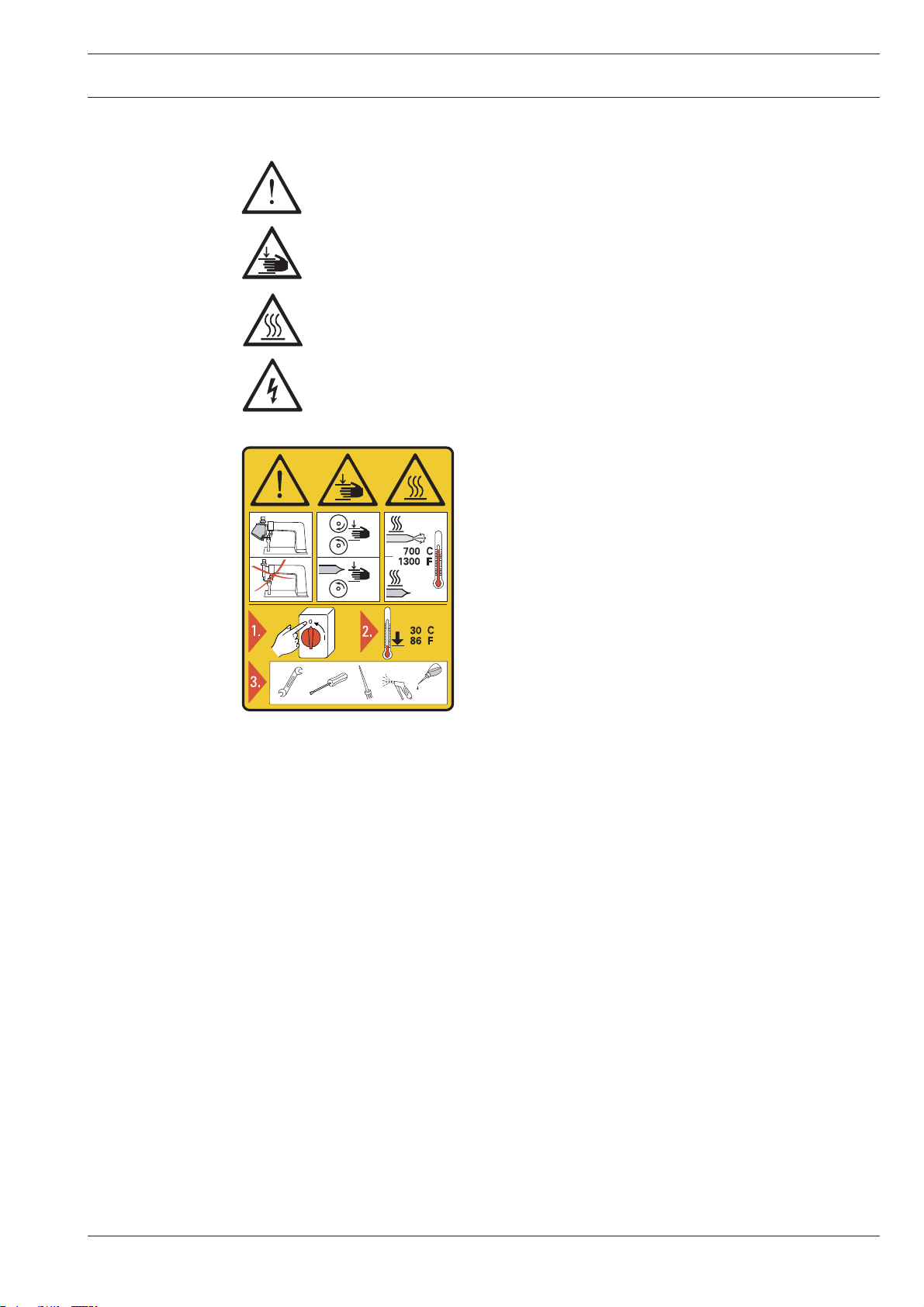
1.03 Safety symbols
Danger!
Special points to observe.
Danger of hands being crushed!
Danger of burns from hot surface!
Danger from electric voltage!
Caution
Do not operate without fi nger guard and safety de-
vices.
1.04 Important notes for the user
This instruction manual belongs to the equipment of the machine and must be available to
the operating staff at all times.
This instruction manual must be read before the machine is operated for the fi rst time. ●
Both operating and technical staff must be instructed on the safety devices of the machi- ●
ne and on safe working methods.
Turn off the main switch and let the machine cool down
before any setting up, maintenance or cleaning work!
It is the duty of the user to operate the machine in perfect running order only. ●
The user must ensure that none of the safety devices are removed nor put out of wor- ●
king order.
The user must ensure that only authorized persons operate and work on the machine. ●
The user must make sure there is no high-frequency welding equipment being operated ●
in direct proximity to the machine that exceeds the EMC limit values according to
EN 60204-31 for the machine.
For further information please refer to your PFAFF agency.
7
Page 8

Safety
8
1.05 Operating and technical staff
1
.05.01 Operating staff
Operating staff are the persons responsible for setting up, operating and cleaning the machi-
ne and for removing any disturbances in the sewing area.
The operating staff is obliged to observe the following points, and must:
●
always observe the notes on safety in this instruction manual!
●
avoid using any working methods which adversely affect the safety of the machine!
●
avoid wearing loose-fitting clothing or jewelry such as necklaces or rings!
●
also ensure that only authorized persons are allowed near the danger area of the
machine!
●
immediately report to the user any changes to the machine that may affect its safety!
1.05.02 Technical staff
Technical staff are persons who have been trained in electrical engineering, electronics and
mechanical engineering. They are responsible for lubricating, servicing and repairing the ma-
chine.
The technical staff is obliged to observe the following points, and must:
●
always observe the notes on safety in this instruction manual!
●
switch off the on/off switch before carrying out any maintenance and repair work on the
machine!
●
never work on parts or equipment still connected to the power supply! Exceptions to this
are only permissible according to regulations EN 50110.
●
replace all safety covers after maintenance and repair work!
Page 9
Safety
9
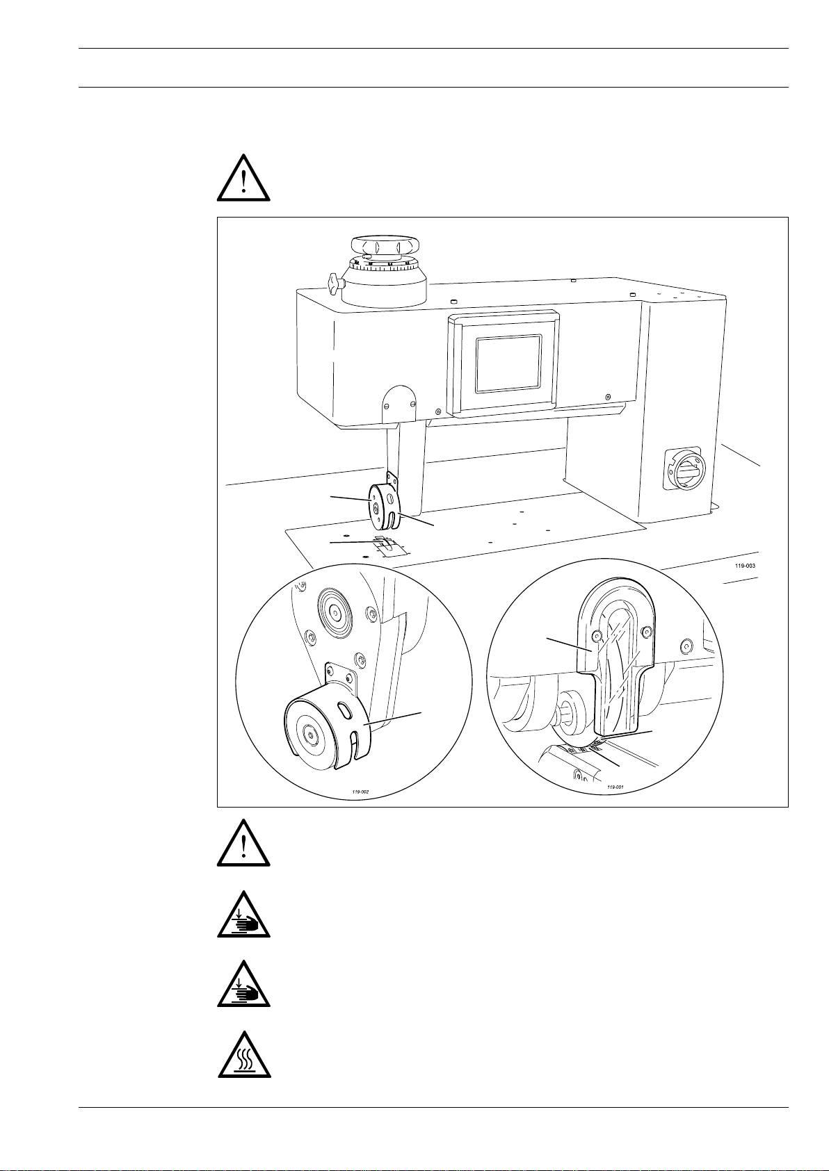
1.06 Danger
When the machine is in operation, a work area of 1 m must be kept free in
front of and behind the machine, so that access to the machine is possible at all
times without difficulty.
Fig. 1 - 01
3
2
4
1
2
4
3
3
Do not operate the post-bed and feed-off-the-arm versions of the machine
without ultrasonic guard 1. Danger of hearing damage!
Do not operate the flat-bed versions of the machine without finger guard 2!
Danger of crushing if the fingers are drawn in!
During operation do not place your hands in the area of feed roller 3 and
sonotrode 4! Danger of fingers being drawn in and crushed!
During operation do not touch sonotrode 4!
Danger of burns from the heat-generating surface!
Page 10
Proper use
10
2 Proper use
2.01 General
2.02 Machine versions
The PFAFF 8310 is available in four versions. The special applications of the individual versi-
ons are described below, see Chapter 2.02 Machine versions. All the machine versions are
used for continuous sealing of thin, thermoplastic materials, such as e.g. fleeces, felts,
woven and knitted fabrics using ultrasonics.
Any use of these machines which is not approved by the manufacturer shall be
considered as improper use! The manufacturer shall not be liable for any dama-
ge arising out of improper use! Proper use shall also be considered to include
compliance with the operation, adjustment, service and repair measures speci-
fied by the manufacturer!
2
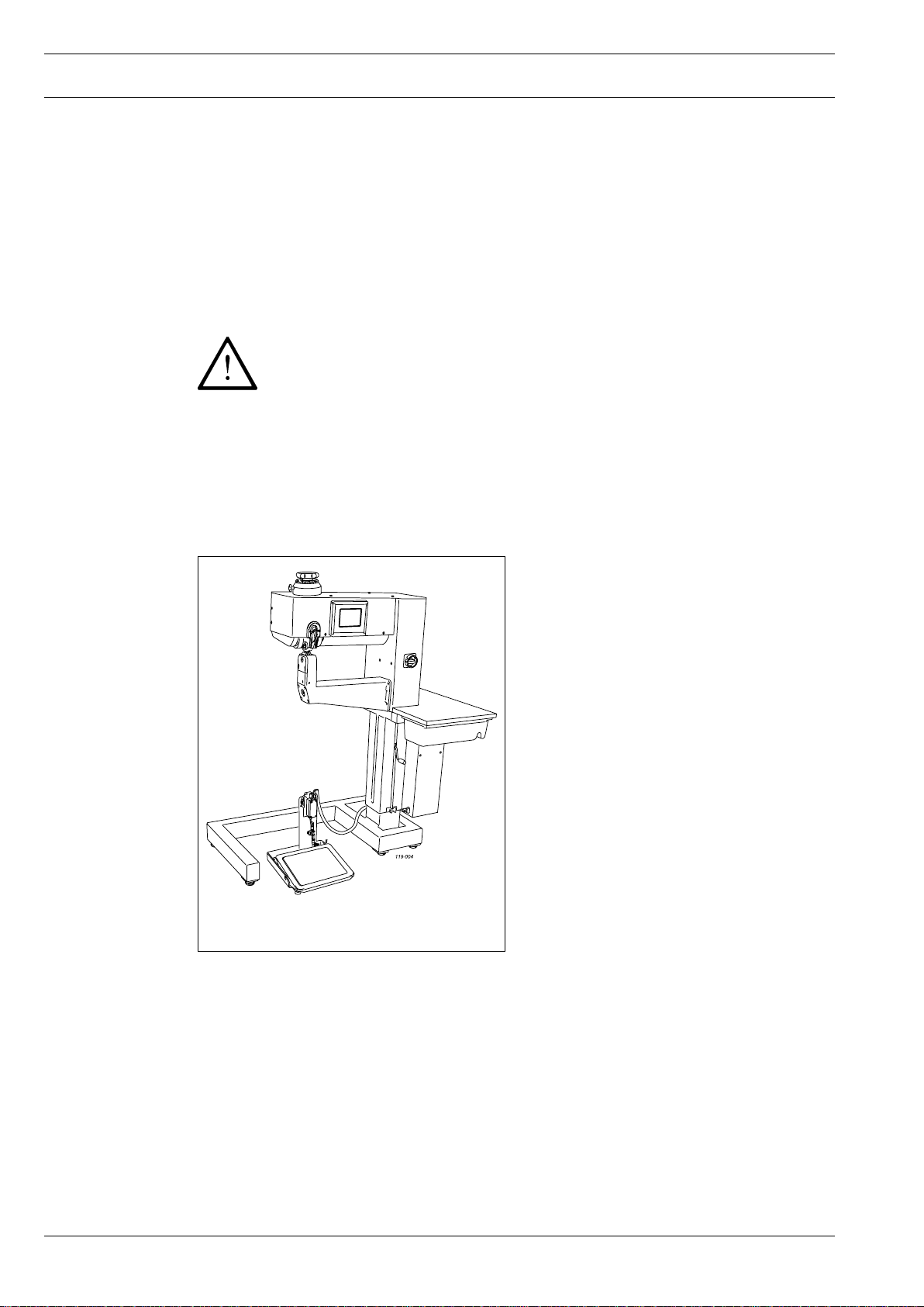
.02.01 Post version (PFAFF 8310-041/001)
Fig. 2 - 01
The post version is particularly suitable for
heat-sealing three-dimensional shapes, such
as e.g. hoods, caps, pouches etc. With the
aid of the post, two parts can be joined to-
gether flat or one part sealed to form a shor-
ter tube. To do so the part is wrapped around
the post and then sealed from out of the
post (e.g. the lengthwise seam of a sleeve
or a filter tube).
On the post-bed version the top roller is the
sonotrode.
Page 11
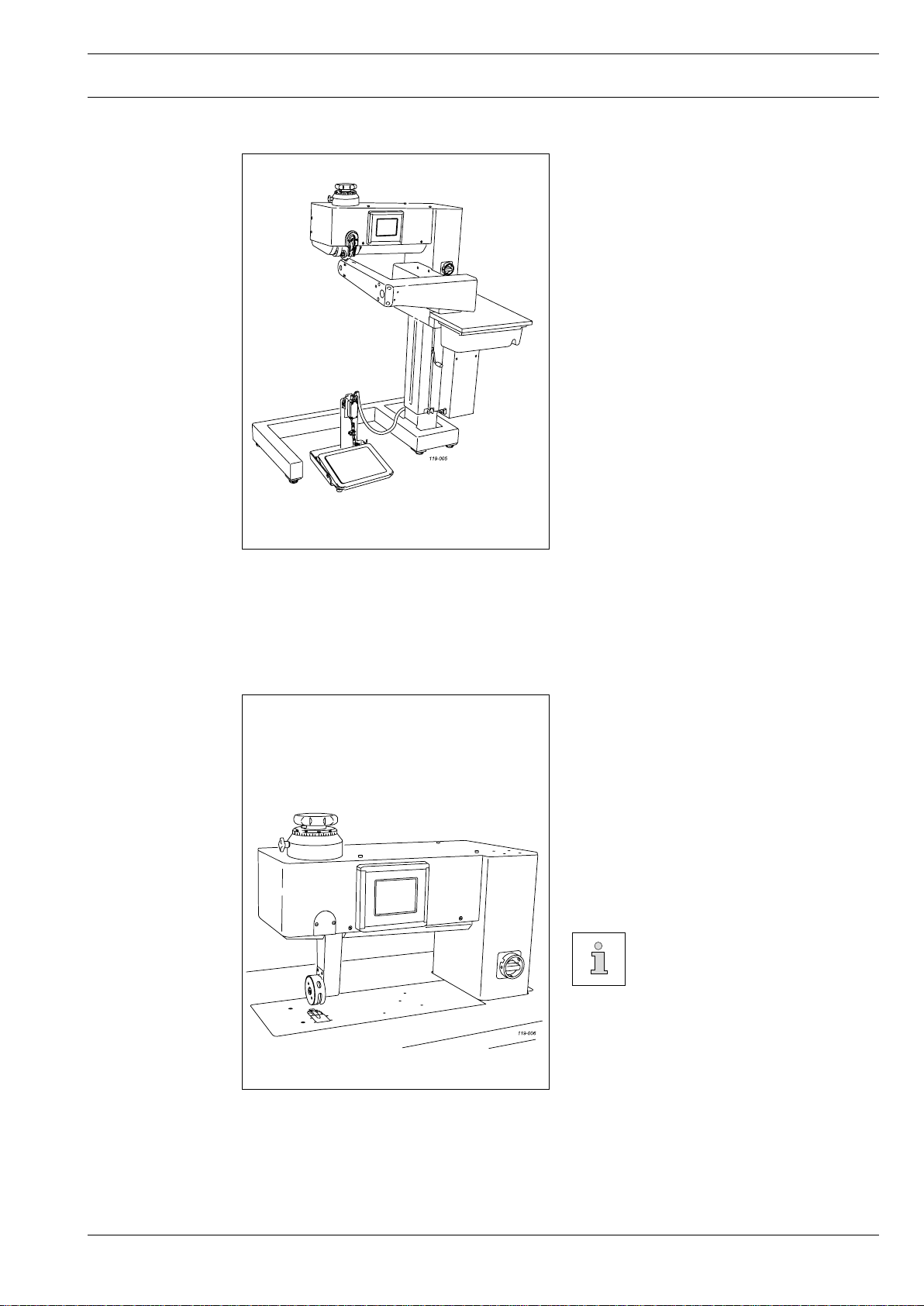
2.02.02 Off arm version (PFAFF 8310-041/002)
Proper use
The off arm version is ideal for heat-sealing
the lengthwise seam of a sleeve or tube
(up to a length of ca. 30 cm). A variation is
also available as a special version, which is
suitable for sealing the lengthwise seam of
a longer or endlessly long tube.
On the feed-off-the-arm version the top
roller is the sonotrode.
Fig. 2 - 02
2.02.03 Flat-bed version (PFAFF 8310-042 und PFAFF 8310-043)
The flat-bed version is used in particular for
sealing two flat parts. Possible seam ty-
pes are lapped seams, peeling seams, top-
stitched and binding seams. The application
possibilities correspond to those of a typical
high-speed sewing machine.
On the flat-bed version the bottom roller is
the sonotrode.
The only difference between
the PFAFF 8310-043 and the
PFAFF 8310-042 is that the for-
mer has a smaller roller enab-
ling a smaller curve radius.
Fig. 2 - 03
11
Page 12

Specifi cations
3 Specifi cations▲
Abmessungen und Gewichte
Version:
8310
Depth:
Width:
Height:
Weight:
Post
-041/001
Off arm
-041/002
Flat-bed
-042, -043
ca. 700 mm ca. 750 mm ca. 600 mm
ca. 1.100 mm ca. 1.100 mm ca. 1.250 mm
ca. 1.300 mm ca. 1.300 mm ca. 1.300 mm
ca. 170 kg ca. 175 kg ca. 145 kg
Clearance width: ...........................................................................................................400 mm
Clearance under the rollers: ............................................................................................25 mm
Connection data
Operating voltage: ..................................................................230 V ± 10%, 50/60 Hz, 1-phase
Max. capacity: ............................................................................................................... 800 kVA
Fuse: .................................................................................................................... 1 x 16 A, inert
Working air pressure: ......................................................................................................... 6 bar
Air consumption: ....................................................................................................... < 10 l/min.
Sealing pressure .............................................................................................................. 750 N
Sealing power: .................................................................................................................500 W
Sealing speed: .................................................................................................. max. 10 m/min.
..................................................................................... (optional max. 20 m/min. or 30 m/min.)
Seam width: ........................................................................................................... max. 10 mm
Noise data
Emission sound level at the workplace: .............................................................LpA < 70 dB(A)
(Noise measurement in acc. with DIN 45 635-48-A-1, ISO 11204, ISO 3744, ISO 4871)
Ambient temperature
85% rel. humidity (condensation not permitted): ...................................................... 5 – 40° C
▲
Subject to alterations
■
KpA = 2,5 dB
■
12
Page 13

Disposal of Machine
4 Disposal of Machine
●
Proper disposal of the machine is the responsibility of the customer.
●
The materials used for the machine are steel, aluminium, brass and various plastic
materials. The electrical equipment comprises plastic materials and copper.
●
The machine is to be disposed of according to the locally valid pollution control regula-ti-
ons; if necessary, a specialist ist to be commissioned.
Care must be taken that parts soiled with lubricants are disposed of separately
according to the locally valid pollution control regulations!
13
Page 14

Transportation, packing and storage
5 Transportation, packing and storage
5.01 Transportation to customer‘s premises
The machines are delivered completely packed.
5.02 Transportation inside the customer‘s premises
The manufacturer cannot be made liable for transportation inside the customer‘s premises
nor to other operating locations. It must be ensured that the machines are only transported
in an upright position.
5.03 Disposal of packing materials
The packing materials of this machine comprise paper, cardboard and VCE fibre. Proper dis-
posal of the packing material is the responsibility of the customer.
5.04 Storage
If the machine is not in use, it can be stored as it is for a period of up to six months, but It
should be protected against dust and moisture.
If the machine is stored for longer periods, the individual parts, especially the surfaces of
moving parts, must be protected against corrosion, e.g. by a film of oil.
14
Page 15

Explanation of symbols
6 Explanation of symbols
In this instruction manual, work to be carried out or important information is accentuated by
symbols. These symbols have the following meanings:
Note, information
Cleaning, care
Lubrication
Maintenance, repairs, adjustment, service work
(only to be carried out by technical staff)
15
Page 16
Controls
16
7 Controls
7
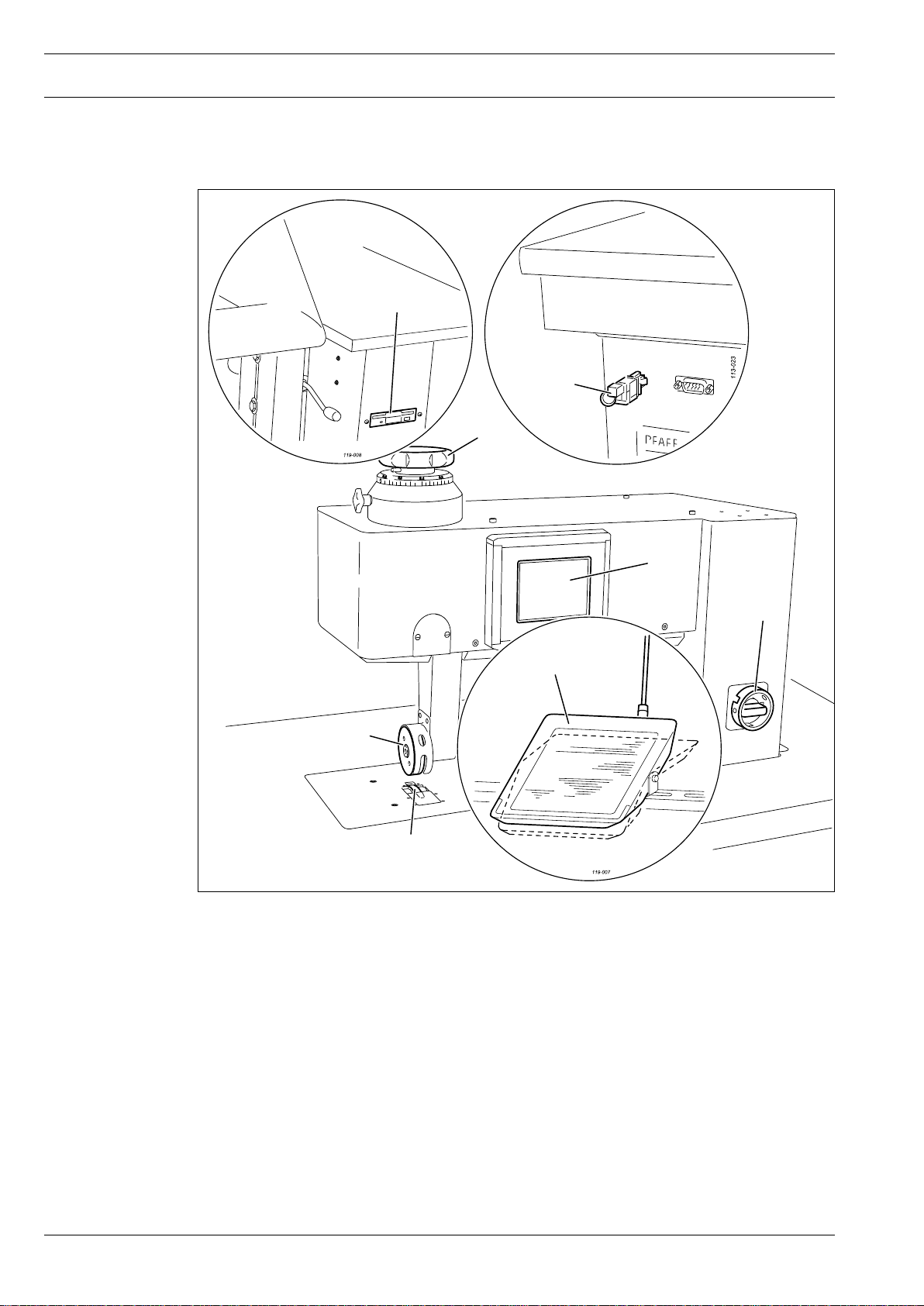
.01 Summary of control elements
8
7
3
5
6
Fig. 7 - 01
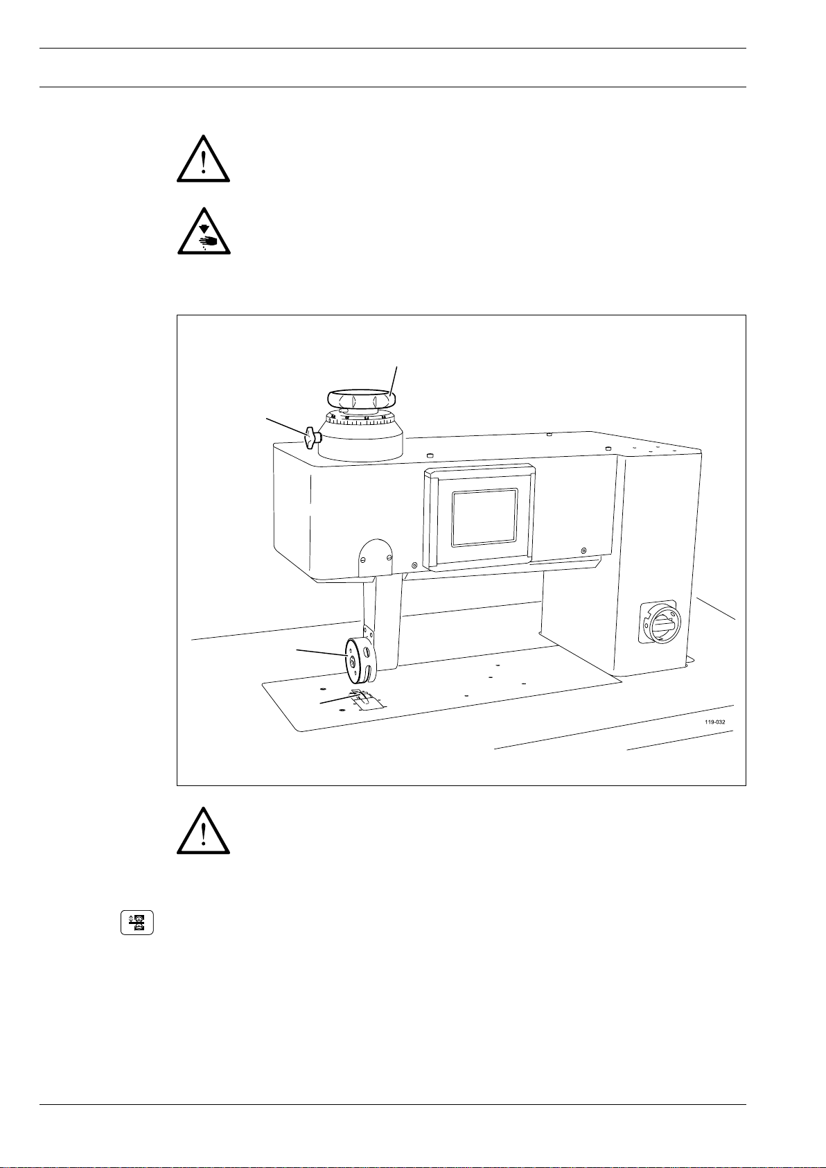
The machine has the following control elements:
●
Main switch 1, see Chapter 7.02
●
Pedal 2, see Chapter 7.03
4
1
2
●
Adjustment wheel 3 for roller clearance, see Chapter 7.04
●
Control panel 4, see Chapter 7.05
●
Top roller 5
●
Bottom roller 6
●
Key switch 7, see Chapter 11.03.03 Rights of access
●
Disk drive 8
Page 17
Controls
113-005
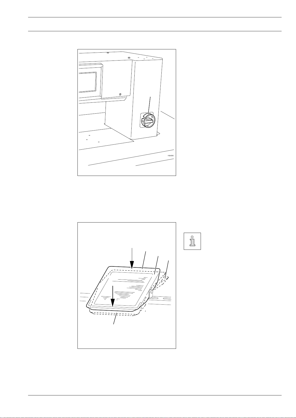
7.02 Main switch
The machine is switched on or off by
●
turning main switch 1.
Position "O": Machine is switched off
Position "I": Machine is switched on
1
Fig. 7 - 02
7.03 Pedal
The function method of the
pedal depends on the selec-
ted pedal mode (level or flip-
0
+1
+2
-1 = Stop sealing operation /
raise top roller
0 = Neutral position
+1 = Lower top roller
+2 = Sealing start
flop mode), see Chapter 11.03
Further settings
-1
Fig. 7 - 03
17
Page 18
Controls
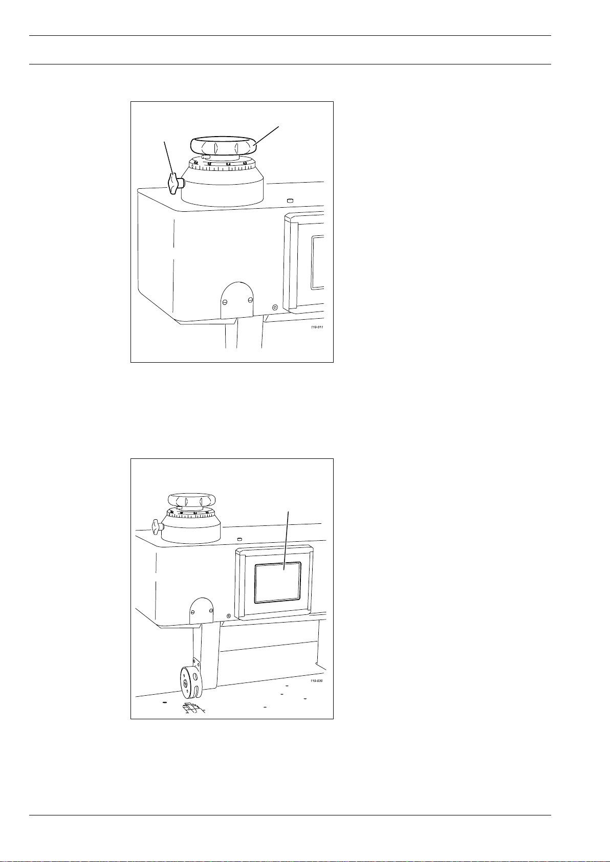
7.04 Adjustment wheel for roller clearance
After loosening clamp screw 1, the clea-
●
2
1
rance between the top and bottom feed
rollers is changed by turning adjustment
wheel 2.
The clearance can be read on the scale.
Fig. 7 - 04
7.05 Control panel
Fig. 7 - 05
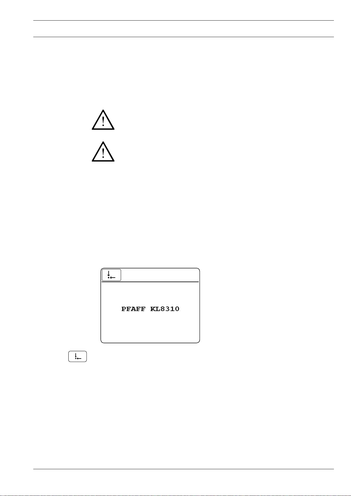
The current operating conditions are displayed on control panel 1. Operation takes
place in a constant dialogue between the
1
control unit and the operator. For this pur-
pose, depending on the operating conditi-
on of the machine, different symbols and/or
texts are displayed. If the symbols or texts
are framed, these show functions which can
be selected by pressing the appropriate po-
sition on the monitor. By pressing the cor-
responding function this is carried out or
switched on or off immediately, or a further
menu appears, e.g. for entering a value. Ac-
tivated functions are shown with inverted
symbols. Unframed symbols or texts are
only used for display purposes and cannot
be selected by pressing.
18
Page 19
Installation and commissioning
8 Installation and commissioning
After the machine has been unpacked, check it for any damages caused during transportati-
on. If there are any damages, please notify the transport company and your
local PFAFF agency.
The machine must only be installed and commissioned by qualified personnel.
All relevant safety regulations must be strictly adhered to!
8.01 Installation
Suitable connections for electricity and compressed air must be available at the machine’s location (see Chapter 3 Specifications). An even and firm foundation as well as sufficient
lighting must also be available at the machine’s location.
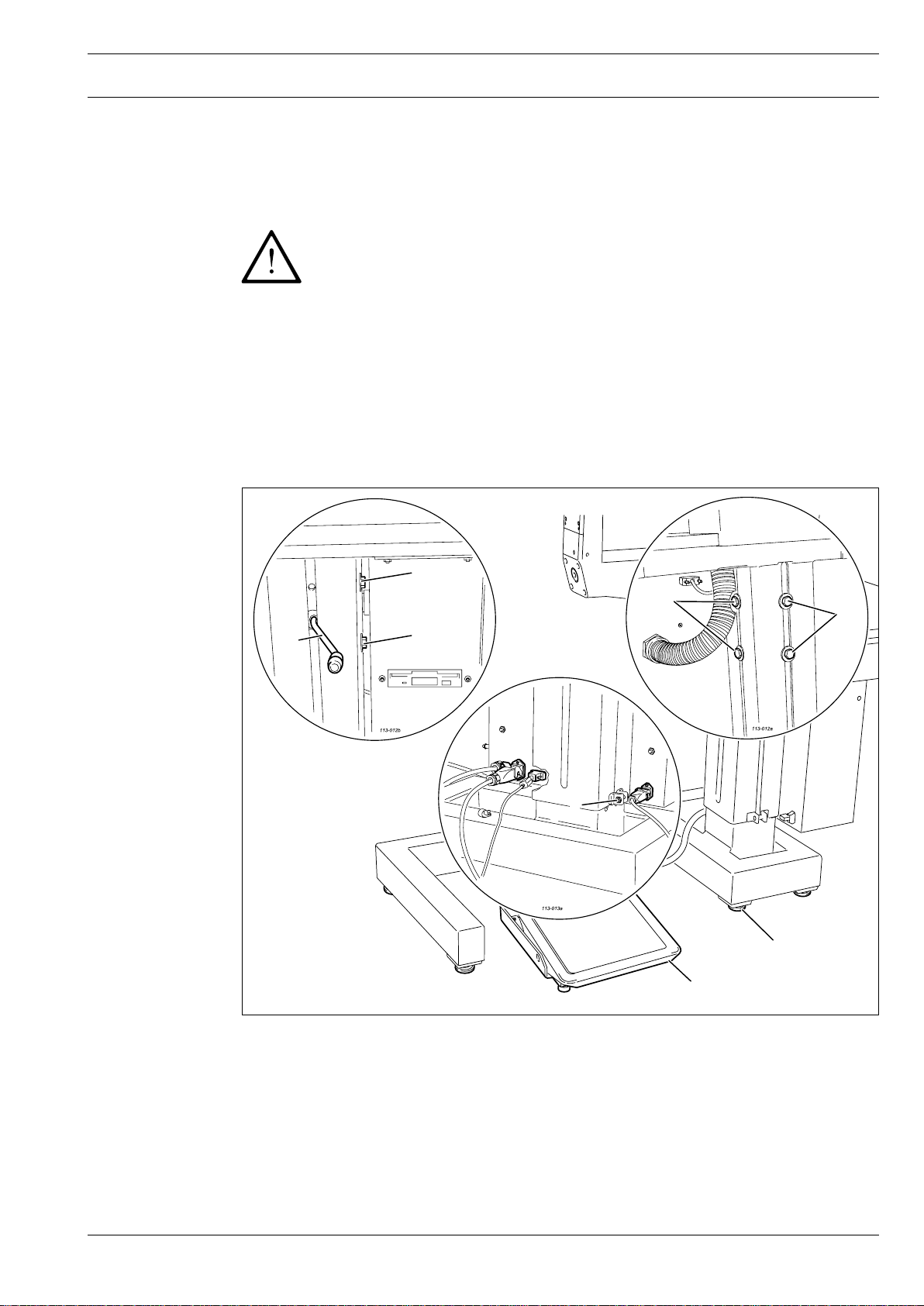
8.01.01 Setting up the PFAFF 8310-041/001 and the PFAFF 8310-041/002
5
Fig. 8 - 01
4
4
4
4
3
1
2
●
Slide the machine off the pallet.
●
Turn the six legs 1 to level the machine horizontally.
●
Connect the plugs from pedal 2 and from any existing foot switches to the control box.
●
Loosen screws 3 and 4 and adjust the height of the machine by turning crank 5.
●
Well tighten screws 3 and 4 again.
19
Page 20

Installation and commissioning
20
8.01.02 Setting up the PFAFF 8310-042 and the PFAFF 8310-043
If the machine is delivered without a table, be sure that the frame and the table
top which you intend to use can hold the weight of the machine and the motor.
It must be ensured that the supporting structure is sufficiently sturdy, even du-
ring sewing operations.
The method of packaging used requires that the table top be lowered for trans-
port. The following is a description of how to adjust the height of the table top.
1
2
2
Fig. 8 - 02
●
Loosen screws 1 and 2 and set the desired table-top height
●
Tighten screws 1 well.
●
Adjust the position of the pedal so that you can operate it comfortably and tighten
screw 2.
1
Page 21
Installation and commissioning
8.02 Commissioning
●
Clean the machine thoroughly, also see Chapter 12 Maintenance.
●
Check the machine, particularly its electrical wiring and pneumatic tube connections, for
any damage.
●
Have a qualified person check whether the motor can be driven with the existing power
voltage.
If there are any differences, the machine must definitely not be operated!
The machine must only be connected to a suitably earthed socket!
●
Connect the machine to the compressed air supply. When it is connected, the gauge
should indicate a pressure of approx. 6 bar. If necessary have this reading correctly set
(see Chapter 12.02 Checking/adjusting the air pressure).
8.03 Switching the machine on/off
To switch on the machine, turn the main switch to the "I" position, see Chapter 7.02 Main
●
switch.
●
Operate the “basic position” function to confirm the switch-on operation.
●
Carry out a test run, see Chapter 10 Sealing
●
To switch off the machine, turn the main switch to the "o" position, see Chapter 7.02
Main switch.
21
Page 22
Preparation
22
9 Preparation
9.01 Adjusting the roller clearance
All regulations and notes in this Service Manual must be observed!
Special attention must be paid to the safety regulations!
All setting-up work must only be carried out by personnel with the appropriate
training!
2
1
4
3
Fig. 9 - 01
Sonotrode 3 and roller 4 must never have direct contact!
Danger of serious damage to the machine!
●
Switch on the machine.
●
Lower the top roller.
●
Loosen clamping screw 1.
●
Adjust the roller clearance to match the workpiece and sealing application with
adjustment wheel 2, see Chapter 7.04 Adjustment wheel for the roller clearance.
●
Tighten clamping screw 1.
Page 23
Preparation
9.02 Selecting a program
The program selection function is used to choose between the types of production
- Manual sealing, see Chapter 10.02,
- Dynamic sealing, see Chapter 10.03,
- Programmed sealing with individual programs, see Chapter 10.06 and
- Programmed sealing with sequences, see Chapter 10.07 or Chapter 10.08
The types of production listed above, particularly their functions, are explained
in more detail in Chapter 10 Sealing.
Switch on the machine, see Chapter 8.03 Switching the machine on/off.
●
Call up program selection.
●
●
Call up manual sealing, the production type, "Manual Sealing" is activated.
or
●
Call up dynamic sealing, the production type "Dynamic Sealing" is activated, the sealing
speed can be controlled by the pedal.
or
●
Select the desired program number on the number block.
●
Confirm selection and quit selection menu, die production type "rogrammed Sealing with
individual program" is activated.
or
●
Call up sequence selection.
23
Page 24
Preparation
24
9.03 Entering the sealing parameters
●
Select the desired sequence number on the number block.
●
Confirm selection and quit selection menu, die production type "Programmed Sealing
with sequence program" is activated.
The direct input and alteration of sealing parameters is only possible in Manual or Dynamic
Sealing. In Programmed Sealing the direct input of the sealing parameters is not possible.
The alteration must be made in the appropriate sealing program, see Chapter 10.05 Crea-
ting/altering a sealing program. Depending on the selected production type and the corres-
ponding pre-settings (power sealing/amplitude sealing) the following parameters can be alte-
red directly:
- Sealing power or sealing amplitude, see Chapter 9.03.01
- Sealing speed, see Chapter 9.03.02
- Roller pressure, see Chapter 9.03.03
●
Switch on the machine, see Chapter 8.03, Switching the machine on/off.
●
Call up program selection.
●
Call up manual sealing.
The screen displays described below only appear if manual sealing is selected.
If dynamic sealing is selected, the sealing speed input is different, see Chapter
9.03.02 Entering the sealing speed.
Power sealing (standard) Amplitude sealing
In Programmed Sealing the direct input of the sealing parameters is not possib-
le. The alteration must be made in the appropriate sealing program, see Chapter
10.05 Creating/altering a sealing program.
Page 25
Preparation
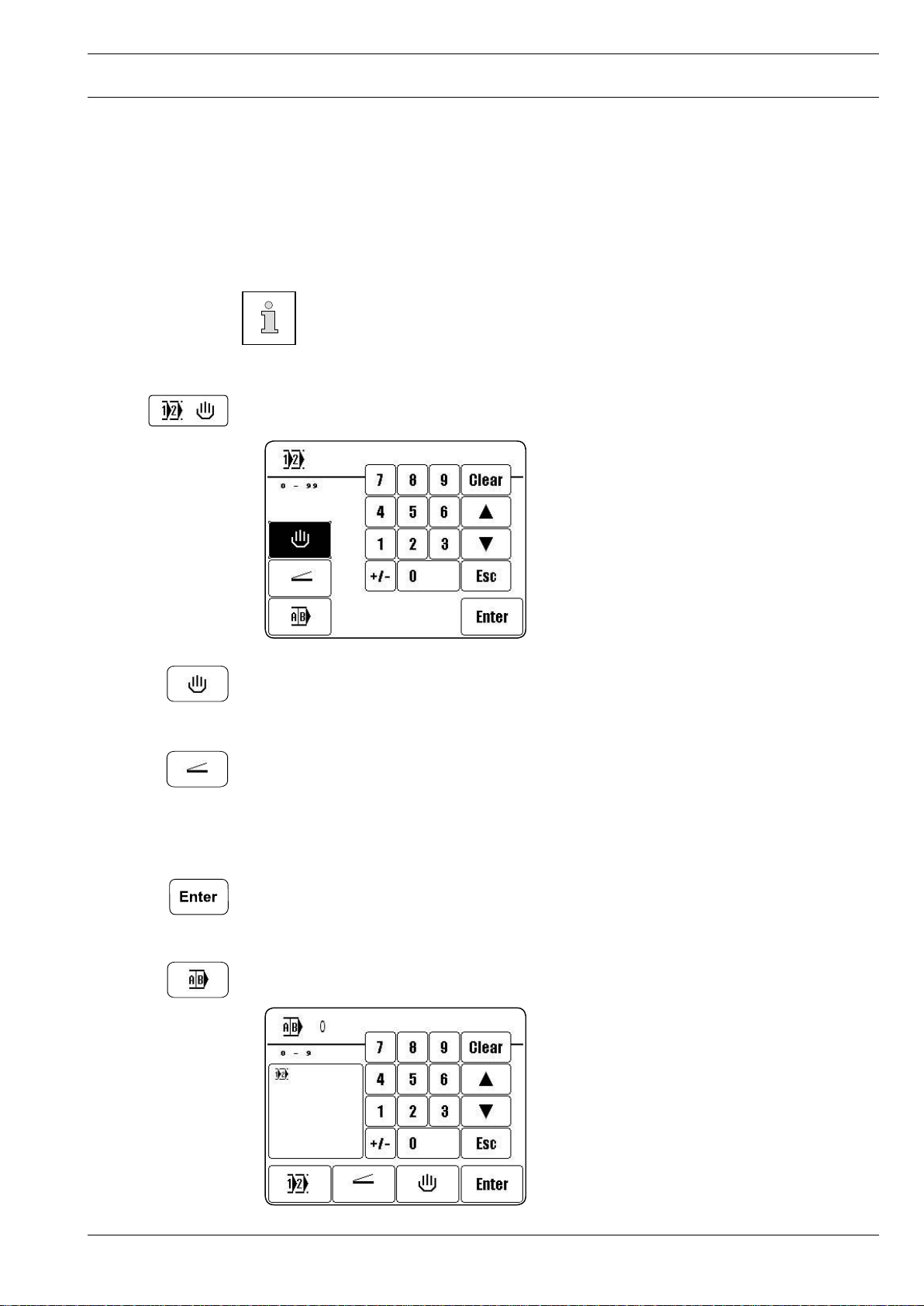
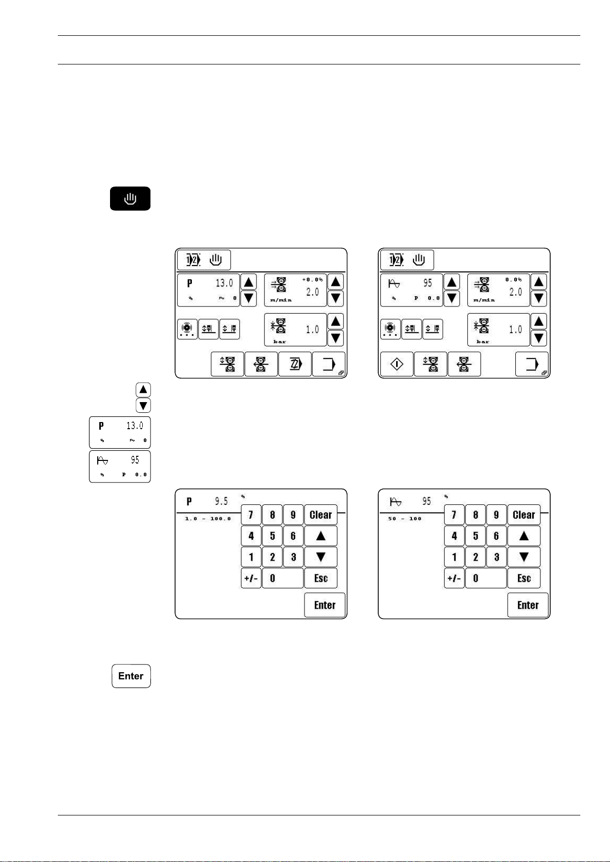
9.03.01 Entering the sealing power or the sealing amplitude
Depending on the presetting of the machine, either the value for the sealing power or the value for the sealing amplitude is altered, see Chapter 11.03 Further settings. During the input
a difference must also be made between manual and dynamic sealing. In the case of manu-
al sealing, a value is fixed for the sealing power or sealing amplitude, in the case of dynamic
sealing a range is fixed for sealing power and sealing amplitude.
Entering the values in manual sealing
Power sealing (standard) Amplitude sealing
Alter the value for sealing power/amplitude directly.
●
or
Call up the number block for entering the sealing power/amplitude.
●
Power sealing (standard) Amplitude sealing
Enter the desired value for sealing power/amplitude on the number block.
●
Conclude the input, permissible values will be taken over.
●
25
Page 26
Preparation
26
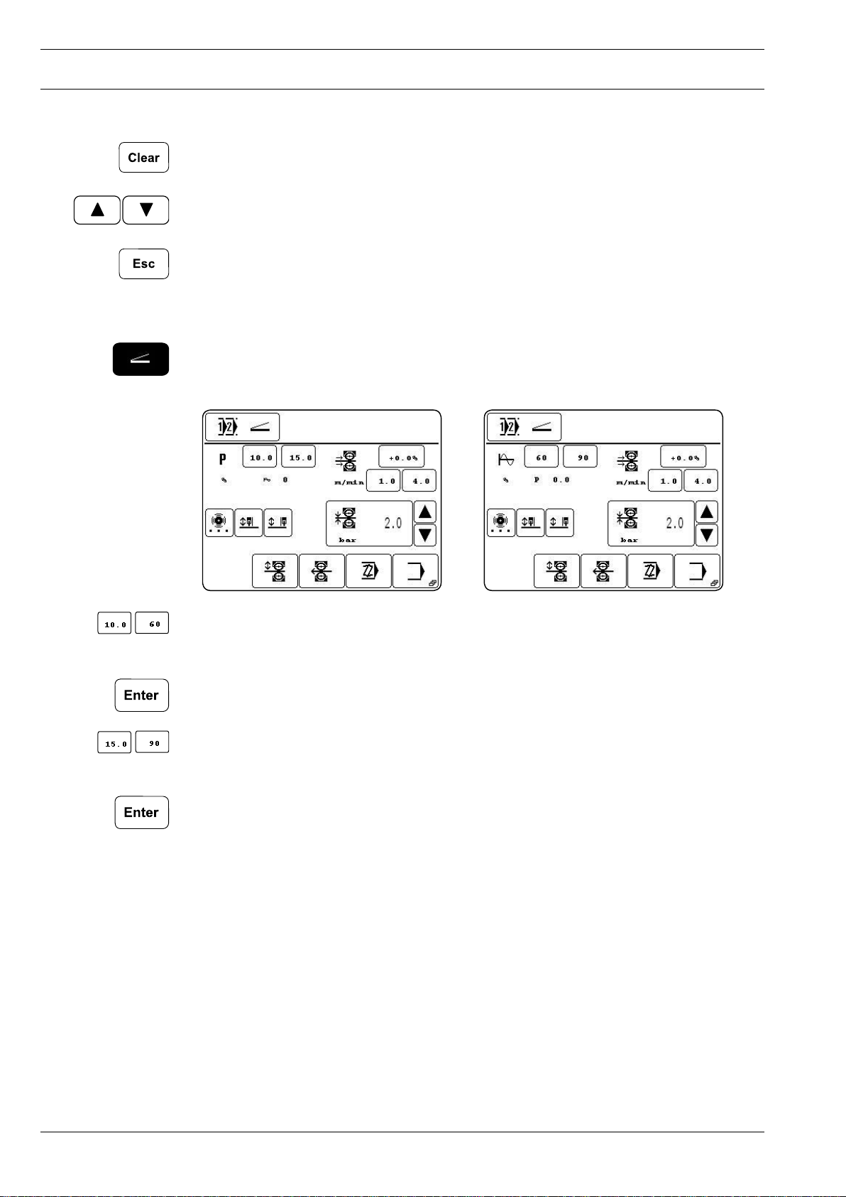
Description of further functions
Clear
When this function key is pressed, the value is set at "0".
Arrow keys
When these function keys are pressed, the value is increased or reduced.
Esc
When this function key is pressed, the input is cancelled without the value entered being ta-
ken over.
Entering the values in dynamic sealing
Power sealing (standard) Amplitude sealing
●
Call up the number block for entering the bottom value for sealing power/amplitude.
●
Enter the desired value on the number block.
●
Conclude the input, permissible values will be taken over.
●
Call up the number block for entering the top value for sealing power/amplitude.
●
Enter the desired value on the number block.
●
Conclude the input, permissible values will be taken over.
Page 27

Preparation
9.03.02 Entering the sealing speed
During the input a difference must be made between manual and dynamic sealing. In the
case of manual sealing, the sealing speed is fixed, in the case of dynamic sealing a speed
range is fixed.
Entering the values in manual sealing
Alter the value for the sealing speed directly.
●
or
Call up the number block for entering the sealing speed.
●
●
If necessary, call up the number block for entering the speed difference between the top
and bottom roller.
●
Enter the value for the speed difference within the permissible range on the number
block.
●
The speed difference results from the change in speed of the top roller, which turns eit-
her more quickly or more slowly than the bottom roller. The value for the speed difference
depends on the material and the application.
●
Conclude the input for the speed difference, permissible values will be taken over.
●
Enter the value for the speed difference within the permissible range on the number
block.
●
Conclude the input for the sealing speed, permissible values will be taken over.
27
Page 28

Preparation
28
Description of further functions
Clear
When this function key is pressed, the value is set at "0".
Arrow keys
When these function keys are pressed, the value is increased or reduced.
Esc
When this function key is pressed, the input is cancelled without the value entered being ta-
ken over.
Further parameters
This function opens a menu for entering the brake and acceleration profile and for setting the
start delay, see Chapter 10.03.05 Entering further sealing parameters.
Entering the values in dynamic sealing
●
Call up the number block for entering the bottom value for the sealing speed.
●
Enter the desired value on the number block.
●
Conclude the input, permissible values will be taken over.
●
Call up the number block for entering the top value for the sealing speed.
●
Enter the desired value on the number block.
●
Conclude the input, permissible values will be taken over.
●
If necessary, call up the number block for entering the speed difference between the top
and bottom roller.
●
Enter the value for the speed difference within the permissible range on the number
block.
The speed difference results from the change in speed of the top roller, which turns eit-
her more quickly or more slowly than the bottom roller. The value for the speed difference
depends on the material and the application.
●
Conclude the input for the speed difference, permissible values will be taken over.
Page 29

Preparation
9.03.03 Entering the roller pressure
Change the value for the roller pressure directly.
●
or
Call up the number block for entering the roller pressure.
●
Enter the desired value for the roller pressure on the number block.
●
Conclude the input, permissible values will be taken over.
●
29
Page 30

Preparation
9.04 Adjusting the control panel
Switch on the machine.
●
Call up the input mode.
●
Select the service menu.●
Select control panel functions. ●
●
Change the display contrast.
●
Switch the key tone off or on.
Never reduce the display contrast to the extent, that the display can no longer
be read!
30
Page 31

Sealing
10 Sealing
The machine may only be operated by properly instructed personnel. The
operating personnel must make sure that only authorised persons are in the
danger zone of the machine.
In particular for the production, in addition to the input mode (see Chapter 11 Input), the
sealing mode is available. Here, depending on the program selection and the machine sta-
tus, all relevant functions and settings for the sealing operation are shown on the display.
In the sealing mode, with the program selection function following production types can be
selected, see Chapter 9.02 Program selection:
Manual sealing, see Chapter 10.02
Dynamic sealing, see Chapter 10.03
Programmed sealing with individual programs, see Chapter 10.06
Programmed sealing with sequences, see Chapter 10.08
10.01 Sealing principle
Due to the vibrations of the sonotrode, the plies of the workpiece are mechanically "ham-
mered" in the seam area. Through the hammering motions of the sonotrode the workpiece
is heated until it becomes viscous and at the same time it is pressed and fed to form the
seam.
In order to achieve optimum sealing results, certain conditions concerning the workpiece
and the machine settings have to be fulfilled.
The workpiece must be:
- sealable (thermoplast),
- suitable for processing with the PFAFF 8310-003 with regard to thickness and properties
and
- clean in the seam area.
The basic requirements on the machine are:
- selection of the correct feed roller and setting
- roller pressure
- sealing power
- sealing speed and
- roller gap (distance of the anvil roller to the sonotrode during sealing).
All settings of the sealing machine are always dependent on the type being
sealed and the ambient temperature. As a result of the influence of the
individual parameters on each other, optimum settings can only be determined
by means of test sealing operations.
31
Page 32

Sealing
32
10.02 Manual sealing
In the manual sealing mode, all relevant parameters for the sealing operation can be entered
or altered directly, see Chapter 9.03 Entering the sealing parameters.
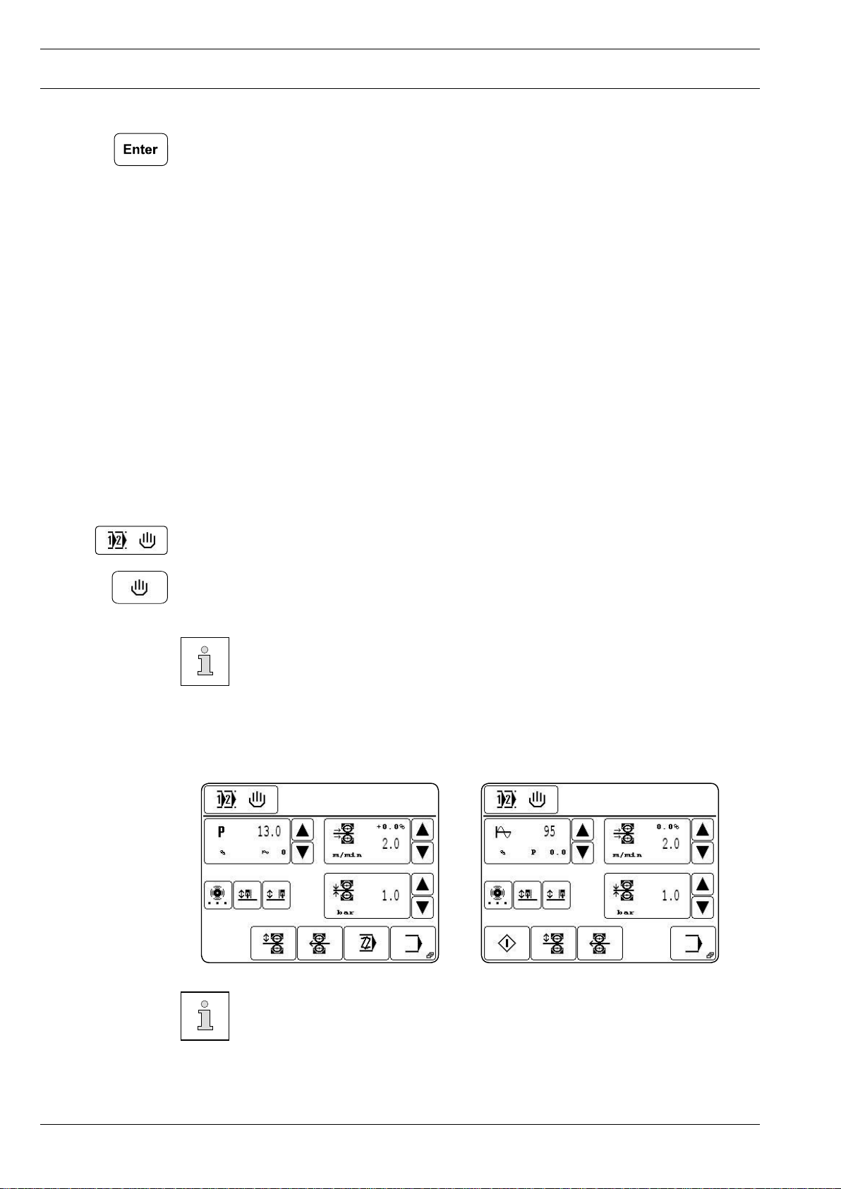
Select Manual Sealing, see Chapter 9.02 Selecting a program●
Power sealing (standard) Amplitude sealing
Description of the functions
Selecting a program
This function opens the menu for entering the program number or for selecting the production type, see Chapter 9.02 Selecting a program.
Sealing power
These functions are used for altering the sealing power, see Chapter 9.03.01 Entering the
sealing power or the sealing amplitude
Sealing amplitude
These functions are used for altering the sealing amplitude, see Chapter 9.03.01 Entering
the sealing power or the sealing amplitude
Sealing speed
These functions are used to alter the feed stroke or to open the menu for entering the feed
stroke difference, the brake and acceleration profiles and the start delay for the rollers, see
Chapter 9.03.02 Entering the sealing speed
Basting
This function opens a menu for entering the sealing parameters for basting, see Chapter
10.04 Basting.
Left secondary roller
This function is used to switch the left secondary roller on or off.
Right secondary roller
This function is used to switch the right secondary roller on or off.
Roller pressure
These functions are used to alter the roller pressure, see Chapter 9.03.03 Entering the rol-
ler pressure.
Page 33

Sealing
Start
(This function appears when the top roller is lowered.)
With this function the sealing start is called up, analogue to the pedal function "+2", also see
Chapter 7.03 Pedal.
Roller up/down
With this function the top roller, depending on its position, can be raised or lowered, analogue to the pedal functions "-1" and "+1", also see Chapter 7.03 Pedal.
Turn rollers
This function opens the menu for turning the rollers, see Chapter 10.10 Turning the rollers.
Programming
These functions are used for creating or altering sealing programs, see Chapter 10.05 Creating/altering a sealing program.
Input menu
This function is used to call up the input mode, see Chapter 11 Input.
Stop
(This function appears during the sealing operation.)
This function is used to stop the sealing operation, analogue to pedal function "-1", also see
Chapter 7.03 Pedal.
Carry out the sealing operation using the pedal functions, see Chapter 7.03 Pedal.●
33
Page 34

Sealing
34
10.03 Dynamic sealing
In the dynamic sealing mode, all relevant parameters for the sealing operation can be entered or altered directly, see Chapter 9.03 Entering the sealing parameters. With the pe-
dal function the sealing power/sealing amplitude and sealing speed can be varied infinitely
within the set range.
Select Dynamic Sealing, see Chapter 9.02 Selecting a program.●
Power sealing (standard) Amplitude sealing
Description of the functions
Selecting a program
This function opens the menu for entering the program number or for selecting the production type, see Chapter 9.02 Selecting a program.
Sealing power
These functions are used for altering the sealing power, see Chapter 9.03.01 Entering the
sealing power or the sealing amplitude
Sealing amplitude
These functions are used for altering the sealing amplitude, see Chapter 9.03.01 Entering
the sealing power or the sealing amplitude
Sealing speed
These functions are used to alter the feed stroke or to open the menu for entering the feed
stroke difference, the brake and acceleration profiles and the start delay for the rollers, see
Chapter 9.03.02 Entering the sealing speed
Basting
This function opens a menu for entering the sealing parameters for basting, see Chapter
10.04 Basting.
Left secondary roller
This function is used to switch the left secondary roller on or off.
Right secondary roller
This function is used to switch the right secondary roller on or off.
Roller pressure
These functions are used to alter the roller pressure, see Chapter 9.03.03 Entering the rol-
ler pressure.
Page 35

Sealing
Start
(This function appears when the top roller is lowered.)
With this function the sealing start is called up, analogue to the pedal function "+2", also see
Chapter 7.03 Pedal.
Roller up/down
With this function the top roller, depending on its position, can be raised or lowered, analogue to the pedal functions "-1" and "+1", also see Chapter 7.03 Pedal.
Turn rollers
This function opens the menu for turning the rollers, see Chapter 10.10 Turning the rollers.
Programming
These functions are used for creating or altering sealing programs, see Chapter 10.05 Creating/altering a sealing program.
Input menu
This function is used to call up the input mode, see Chapter 11 Input.
Stop
(This function appears during the sealing operation.)
This function is used to stop the sealing operation, analogue to pedal function "-1", also see
Chapter 7.03 Pedal.
Carry out the sealing operation using the pedal functions, see Chapter 7.03 Pedal.●
35
Page 36

Sealing
36
10.04 Basting
With the basting function sealing is performed point for point (without feed stroke) in accor-
dance with specified parameters.
Call up manual sealing or dynamic sealing, see Chapter 9.02 Selecting a program.
●
Call up basting.
●
Power sealing (standard) Amplitude sealing
Description of the functions
Sealing
This function is used to change to the sealing mode.
Sealing power
These functions are used for altering the sealing power, see Chapter 9.03.01 Entering the
sealing power or the sealing amplitude
Sealing amplitude
These functions are used for altering the sealing amplitude, see Chapter 9.03.01 Entering
the sealing power or the sealing amplitude
Hold time
These functions are used to alter the time, after which the top roller is raised again after the
end of the sealing time
Sealing time
These functions are used to alter the sealing time.
Roller pressure
These functions are used to alter the roller pressure, see Chapter 9.03.03 Entering the rol-
ler pressure.
Enter the parameter for basting according to the material to be sealed.
●
Start the basting operation with the pedal function "+1", see Chapter 7.03 Pedal.
●
Page 37

Sealing
10.05 Creating/altering a sealing program
Up to 100 sealing programs (0 – 99) each with up to 20 sealing zones can be filed and mana-
ged in the machine memory.
With the programming function it is possible to enter the programming function of the
●
sealing programs. A number block for entering the desired program number appears on
the display.
Creating a new program Altering a program
If no program is filed in the memory under the program number selected, the current
sealing parameter of the manual sealing function will be taken over and a new program cre-
ated.
As an alternative to the creation of a new program, the program number of an existing program (e.g. 50) can be selected, and this program can be changed or copied to create a new
program. In the case of existing programs, the number of zones and possibly a comment are
displayed next to the program number in the headline.
Enter the program number, e.g. "50".
●
Confirm selection.
●
The first zone of the selected program is displayed on the screen with functions for ente-
ring sealing parameters, notes, switching to the next zone, as well as basic functions for the
program input. For further descriptions of the functions see Chapter 10.05.07 Example for
sealing program input.
37
Page 38

Sealing
38
10.05.01 Notepad
When creating a sealing program, this function is used to enter data about the sealing tools
for the program. The data serves as information for the operator and can be called up in the
programmed sealing mode.
Press the relevant key panels to enter the data.●
Enter the relevant data.
●
Conclude the input
●
Page 39

Sealing
10.05.02 Basic functions for the program input
The following functions are used to enter the basic information for the currently selected
program. In addition to functions for navigating in the different zones and functions for inser-
ting and deleting zones, depending on the zone displayed, functions can be called up for en-
tering further parameters and comments as well as for concluding the program input.
Call up the appropriate functions to process or conclude the program.
●
Description of the functions
Selecting a zone
These functions are used to switch forwards and backwards to other zones in the current
program.
Insert
This function inserts a new zone at the current location. The data of the current zone are co-
pied for the new zone and the following zones are moved one place back.
Delete
This function deletes the current zone.
Further sealing parameters
(This function only appears in the first zone.)
This function opens a menu for entering further sealing parameters.
Comment
(This function only appears in the first zone.)
With this function, when entering a note, see Chapter 10.05.01 Notepad, the analog ent-
ry of a comment about the current program is possible. The comment is displayed as informati-
on about the appropriate program in the program selection and program management functions.
Add
(This function only appears in the last zone.)
This function is used to copy the data of the current zone and add it as a new zone.
Conclude programming
This function concludes the programming, see Chapter 10.05.06 Concluding the programming.
39
Page 40

Sealing
40
mm
10.05.03 Sealing parameters
10.05.04 Functions for switching to other zones
Sealing parameters for each zone as described in Chapter 9.03 Entering sealing para-
●
meters.
In addition to the sealing parameters, further functions can be allocated to each zone, which
serve to enable the automatic switch to other zones and a more exact setting of the sealing
operation sequence.
Select appropriate functions for each zone, activated functions are displayed as inverse
●
symbols on the screen.
Description of the functions
Programmed section
This function is used to determine the length of the current zone. The value in millimetres is
entered on the appropriate number block. When the function is activated, the machine swit-
ches to the next seam zone after processing the entered section.
Programmed stop
When this function is switched on, the current zone takes on a stop function. The sealing
operation stops and the machine moves to the next zone. The sealing parameters entered
for this zone are not taken into account.
Programmed output
When this function is switched on, the current zone takes on an output switch function. Two
outputs can be stipulated with the appropriate menu. The sealing parameters entered for
this zone are not taken into account.
Programmed input
When this function is switched on, the machine does not switch to another zone until an ap-
propriate input signal is given or not given. The two different inputs can be set up with the
appropriate menu.
Sealing on/off
When this function is switched on, the current zone takes on a switch function. The sealing
operation is switched off or on and the machine switches to the next zone. The sealing func-
tion remains switched off/on for the following zones, until the setting is altered again.
Page 41

Sealing
10.05.05 Entering further sealing parameters
Further sealing parameters can be entered either
- from the Manual Sealing mode in conjunction with the sealing speed input or
- when creating programs in conjunction with the input of the first zone..
Input from manual/dynamic
sealing mode
●
Select acceleration and brake profile of the feed rollers, dependent on the material for
sealing. Each of the profiles selected is displayed as an inverse symbol. A flat ramp
stands for slight acceleration of the feed rollers. The selection of a steep ramp means
high acceleration.
If the sealing result is unsatisfactory, the alteration of the acceleration or brake
profile can lead to an improvement.
The values of the different acceleration and brake profiles can be stipulated in
the input mode, see Chapter 11.03.02 Feed roller parameters.
Input during
program creation
●
Increase or reduce the start delay for the feed rollers directly.
or
●
Call up the figure panel to enter the start delay.
●
Using the number block, enter the start delay time depending on the work material.
●
Conclude the input, permissible values will be taken over.
The start delay function is used to stipulate the amount of time which should
pass between the engaging of the heating element and the start of the feed rol-
lers.
41
Page 42

Sealing
42
10.05.06 Concluding programming
Once all the details for programming have been entered, the programming can be concluded
by pressing the appropriate function key.
Description of the functions
Esc
The input is interrupted and the machine moves back to the basic programming condition.
Discard alterations
All program alterations are cancelled.
Save as…
If this function key is pressed, the number panel opens to enter any program number.
Enter
All program alterations are saved under the current program number.
Page 43

Sealing
10.05.07 Example of how to enter a sealing program
The following example should be filed under program number "10" with the comment
"PROG10", and should consist of three seam zones:
- Seam zone 1 with switch to another zone after 200 mm seam length
- Seam zone 2 with reduced sealing speed and speed difference between the top and bot
tom feed roller, and switch to another zone after 100 mm
- Seam zone 3 with original sealing speed without speed difference between the feed
rollers and with switch to another zone after 400 mm
Switch on the machine.
●
Call up the programming function.
●
Enter program number "10".●
Confirm input.
●
The sealing parameters from the manual sewing mode are taken over for seam zone 1.
43
Page 44

Sealing
44
mm
Call up comment input.●
Enter the term "PROG" using the appropriate symbols.
●
Change to number input.
●
Enter number "10" with the appropriate symbol.
●
Conclude the comment input.
●
●
Activate the switch to another zone using the seam length.
●
Enter the value "200" as seam length with the number panel.
●
Conclude the activated function for switching to another zone.
Page 45

Sealing
mm
Add seam zone 2.●
Alter the values for sealing speed and speed difference, also see Chapter 9.03.02 Ente-
●
ring the sealing speed.
Activate the switch to another zone with the value "100" as seam length.
●
Conclude the input of seam zone 2.●
45
Page 46

Sealing
46
mm
●
Add seam zone 3.
●
Reset the values for sealing speed and speed difference.
●
Activate the switch to another zone with the value "400" as seam length.
●
Conclude the input of seam zone 3.
Conclude programming.●
Reconfirm the sealing program input.
●
The programmed sealing function is called up to process the created sealing program.
Page 47

Sealing
10.06 Programmed sealing with individual programs
In the headline, in addition to the program number of the selected program, the number of
zones, the current zone and the comment for the program are displayed. For the current
zone all heat-sealing parameters are displayed. The heat-sealing parameters have been stipu-
lated during programming and cannot be processed without changing the program.
Select the desired program, see Chapter 9.02 Selecting a program.●
Description of the functions
Program selection
The function opens the menu for entering the program number or for choosing the
production type, see Chapter 9.02 Selecting a program.
Notepad
This function opens the notepad with program details about the heat-sealing tools to
be used.
Basting
This function opens a menu for entering the sealing parameters for basting, see Chapter
10.04 Basting.
Start
(This function appears, when the top feed roller is lowered.)
This function is used to call up the sealing start, analog to pedal function "+2", also see
Chapter 7.03 Pedal.
Feed roller up/down
This function is use to raise or lower the top feed roller, depending on its position, analog to
the pedal functions "-1" and "+1", also see Chapter 7.03 Pedal.
Turn rollers
This function opens the menu for turning the rollers, see Chapter 10.10 Turning the rollers.
Programming
These functions are used to enter the Creating or Altering Heat-Sealing Programs, see
Chapter 10.03 Creating/altering sealing programs.
Input menu
This function is used to call up the "Input" mode, see Chapter 11 Input.
47
Page 48

Sealing
48
10.07 Creating/processing sequences
Stop
(This function appears during the heat-sealing operation.)
This function is used to stop the heat-sealing operation, analog to pedal function "-1", also
see Chapter 7.03 Pedal.
In sequences up to 8 sealing programs are combined in any order whatever and filed under a sequence number. A total of up to 10 sequence programs can be filed in the machine’s
memory.
To enter sequence programming, first of all call up the Program selection function.
●
Call up the Sequence Selection function.
●
Select the desired sequence number on the number block.
●
Call up sequence programming.
●
●
Compile a sequence from the existing individual programs by entering the program num-
bers on the number block.
The cursor in the window shows which program is being deleted or at which point a new
program is being inserted. The cursor can be moved with the arrow keys.
●
Insert the program (INS) at the current cursor position or delete (DEL) a marked program
from the sequence, as required.
●
Conclude sequence programming.
Page 49

Sealing
10.08 Programmed sealing with sequences
In the headline, in addition to the sequence number of the selected sequence, the num-
ber of zones, the current zone and the comment for the current program are displayed. For
the current zone all heat-sealing parameters are displayed. The heat-sealing parameters have
been stipulated during programming and cannot be processed without changing the pro-
gram. In addition, in the case of sealing with sequence programs, the individual programs
belonging to the sequence are displayed, and the current program is shown here as an inver-
se symbol.
Select the desired sequence, see Chapter 9.02 Selecting a program.●
Description of the functions
Program selection
The function opens the menu for entering the program number or for choosing the
production type, see Chapter 9.02 Selecting a program.
Notepad
This function opens the notepad with program details about the heat-sealing tools to be
used.
Sealing program
Press this function to select the appropriate sealing program.
Basting
This function opens a menu for entering the sealing parameters for basting, see Chapter
10.04 Basting.
Start
(This function appears, when the top feed roller is lowered.)
This function is used to call up the sealing start, analog to pedal function "+2", also see
Chapter 7.03 Pedal.
Feed roller up/down
This function is use to raise or lower the top feed roller, depending on its position, analog to
the pedal functions "-1" and "+1", also see Chapter 7.03 Pedal.
Turn rollers
This function opens the menu for turning the rollers, see Chapter 10.10 Turning the rollers.
49
Page 50

Sealing
50
10.09 Error messages
Programming
These functions are used to enter the Creating or Altering Heat-Sealing Programs, see
Chapter 10.03 Creating/altering sealing programs.
Input menu
This function is used to call up the "Input" mode, see Chapter 11 Input.
Stop
(This function appears during the heat-sealing operation.)
This function is used to stop the heat-sealing operation, analog to pedal function "-1", also
see Chapter 7.03 Pedal.
In case of a malfunction, an error code appears on the display. An error message may be
caused by incorrect handling, faults on the machine or by overload conditions.
For the explanation of the error code, see Chapter 13.11 Explanation of the error numbers.
●
Eliminate the error.
●
Acknowledge the elimination of the error.
10.10 Turning the rollers
●
Call up manual sealing or dynamic sealing, see Chapter 9.02 Selecting a program.
●
Call up the function for turning the rollers.
Page 51

Sealing
Description of the functions
Input mode
This function is used to change to the initial state of the input mode.
Sealing mode
This function is used to change to the sealing mode.
Turning speed
This function is used to change the turning speed of the rollers.
Feed direction
This function is used to change the feed direction of the rollers.
Start
After this function is activated, the rollers start turning.
Stop
After this function is activated, the turning motion of the rollers is stopped.
51
Page 52

Input
52
11 Input
Contained in the input mode are the functions for displaying information, for program ma-
nagement, for machine adjustment and configuration (incl. choice of country and access
rights), as well as for supporting service and adjustment work.
11.01 Summary of the functions in the input mode
Switch on the machine.
●
Call up the input mode
●
Description of the functions
Sealing mode
This function is used to change to the sealing mode.
Info
This function opens a menu to display the following information:
- Current software status of the machine
- Current firmware status of the machine
- Current firmware status of the control panel
- Measured sealing power/amplitude
- Number of operating hours (can be reset with the Clear function)
- Number of production hours (can be reset with the Clear function)
Program management
This function is used to manage the data from the machine memory and disks, see Chapter
11.02 Program management.
Further settings
This function is used to call up a menu for stipulating further machine settings, the choice of
country and the access rights, see Chapter 11.03 Further settings.
Service menu
This function is used to call up the menu for selecting various service functions, see Chapter
13.12 Service menu.
Daily piece counter
This function is used to call up the daily piece counter. The daily piece counter can be reset
with the Clear function.
Page 53

Input
Feed rollers forwards
This function makes it possible to turn the feed rollers forwards at a freely selectable speed.
For this purpose a menu is opened with functions for selecting the speed of the feed rollers
and for starting or stopping the feed rollers.
Turn rollers
This function opens the menu for turning the rollers, see Chapter 10.10 Turning the rollers.
Blocking the rollers
This function is used to block the rollers, in order to facilitate a roller change. A menu is ope-
ned with a function for releasing the blocking function again.
11.02 Program management
The program management function is used to manage sealing programs as well as configu-
ration and machine data. Files can be selected from the machine memory or from a disk and
be copied or deleted.
●
Switch on the machine.
●
Call up the input mode.
●
Call up the program management function.
Both data carriers with the corresponding files appear on the display:
- Machine memory ("C:\DATEN\") is currently selected
- Disk ("A:\) is not inserted at present (NO DISK)
The data carrier is selected by touching the appropriate box. The content of the appropriate
data carrier is also updated. The selected data carrier and the selected files are shown as in-
verse symbols:
Sealing programs are filed at a different level to that for the configuration and
machine data, in order to avoid the configuration and machine data being pro-
cessed by mistake.
53
Page 54

Input
54
Description of the functions
Input mode
This function is used to change from the initial state to the input mode.
Sealing mode
This function is used to change to the sealing mode.
Data selection
With these functions the desired files are marked in the current drive. Individual files are se-
lected with the arrow keys. In combination with the Lock key (*) several files can be selected
at one time with the arrow keys.
Copy
This function is used to copy the files selected from the current data carrier onto the second
data carrier.
Delete
This function is used to delete the selected files.
MDAD/KONF
This function is used to call up the level for the configuration and machine data. The current
settings and the machine configuration are stored in the files "MDAT8310" and "KONF8310.
BIN". In this way the machine data can be copied on to a disk as a backup, or several machi-
nes with the same designation can be configured quickly by reading the machine data.
Format
This function is used to format the disk inserted.
In the course of the formatting operation, all data on the disk is deleted!
Page 55

Input
11.03 Further settings
The further settings are use for stipulating further machine settings, the choice of country
and access rights.
●
Switch on the machine.
●
Call up the input mode.
●
Call up the input menu for further settings.
Power sealing (standard) Amplitude sealing
Description of the functions
Input mode
This function is used to change from the initial state to the input mode.
Sealing mode
This function is used to change to the sealing mode.
Feed unit backwards after stop
This function is used to enter the distance which the feed unit should move back after a
sealing stop.
Feed unit forwards at end
This function is used to enter the distance which the feed unit should continue moving after
the end of the sealing.
Automatic recognition of ply (only for power sealing)
This function is used to switch the automatic ply recognition function on or off, see Chapter
11.03.01 Automatic ply recognition.
Flip-flop mode (pedal)
This function is used to switch the flip-flop mode for the pedal function on or off:
- Function switched on (symbol shown inverse)
The pedal function is carried out as soon as the pedal is brought into the appropriate
position and remains active after the pedal has been released.
- Function switched off
The pedal function is only carried out as long as the pedal is held in the appropriate
position.
55
Page 56

Input
56
Feed roller parameters
This function opens a menu for entering the feed roller parameters, see Chapter 11.03.02
Feed roller parameters.
Amplitude window
This function is used to set the permissible difference between the actual and the required
value for the sealing amplitude. If the actual value is outside the defined range, an error message is displayed, see Chapter 10.09 Error messages.
Power window
This function is used to set the permissible difference between the actual and the required
value for the sealing power. If the actual value is outside the defined range, an error message is displayed, see Chapter 10.09 Error messages.
Selection power sealing/amplitude sealing
This function is used to select the sealing type directly.
Country settings
This function opens a menu for setting the language and measuring units for each country.
Right of access
This function calls up the menu for defining access rights, see Chapter 11.03.03 Rights of
access.
Page 57

Input
11.03.01 Automatic ply recognition
In this menu all relevant parameters are determined, which are required for the automatic
ply recognition.
●
Switch on the machine.
●
Call up the input mode.
●
Call up further settings.
●
Call up the menu for entering the parameters for the automatic ply recognition.
4
8
Description of the functions
Input mode
This function is used to change from the initial state to the input mode.
Further settings
This function is used to call up the menu for entering further settings.
Sealing mode
This function is used to change to the sealing mode.
Setting the sensitivity to change in material ply
This function is used to enter the sensitivity to a change in the ply thickness. The thicker the
material (the ply change), the higher the level for this value.
These functions are used to set the time for reaction to a change in ply. This is the time
which passes from the initial recognition of a ply change to the actual reaction of the machi-
ne. The more even the structure of the work material, the lower the setting for this value.
Each time there is a change in the material ply, a signal sounds.
The setting of both values for the sensitivity is correct, if an actual ply change is
recognized reliably and quickly, and if during the sealing of the normal plies the-
re is no case of a “recognition” (no signal).
57
Page 58

Input
58
The reaction to a recognition of a ply change can take place either in one or two
steps.
One-step ply change
This function is used to activate the one-step ply change. A menu is opened for entering the
required parameters.
With the corresponding functions the values for
- sealing speed,
- sealing power and
- max. seam length
can be entered for the ply change section.
The sealing parameters are reset automatically at the end of ply change section
or at the latest after the maximum seam length has been sewn.
Two-step ply change
This function is used to activate the two-step ply change. A menu is opened for entering the
required parameters.
With the corresponding functions the values for
- sealing speed,
- sealing powers and
- max. seam lengths
can be entered for both ply change sections.
Page 59

Input
11.03.02 Feed roller parameters
In this menu the relevant parameters for the feed rollers are preset.
●
Switch on the machine.
●
Enter the input mode.
●
Call up further settings.
●
Call up the menu for entering the feed roller parameters.
Description of the functions
Input mode
This function is used to change from the initial state to the input mode.
Further settings
This function calls up the menu for entering further settings again.
Sealing mode
This function is used to change to the sealing mode.
Acceleration and brake profiles
This function is used to enter the values for the corresponding acceleration or brake profiles.
Feed roller pressure limit
This function is used to enter the maximum permissible value for the feed roller pressure.
Basic position of the top feed roller
This function is used to select the basic position of the top feed roller. The basic position of
the feed roller can be raised or lowered.
Size of the feed difference
This function is used to stipulate the size of the feed difference of the feed rollers (only with
the triple foot switch, which is available as an option)
59
Page 60

Input
60
Reversing the feed direction
This function is used to switch the complete reversing function of the feed direction on or
off.
11.03.03 Rights of access
The functions, which can be called up with the control panel, are classified by code numbers
and can be protected from unauthorised access. For this purpose, the control unit differentiates between 3 user groups (user 1, 2 and 3), all of which can be assigned a corresponding
PIN. If a function is selected, for which the user does not have an authorisation, the user is
requested to enter a PIN. After the appropriate PIN has been entered, the selected function
is carried out. In addition to the 3 user groups, the control unit also recognises the so-called
"super user", who, equipped with a key-switch, has access to all functions and who is autho-
rised to stipulate the rights of access.
●
Enter the key-switch and switch on the machine.
●
Call up the input mode.
●
Call up further settings.
●
Call up the menu for entering rights of access.
Description of the functions
Input mode
This function is used to change from the initial state to the input mode.
Further settings
This function calls up the menu for entering further settings again.
Sealing mode
This function is used to change to the sealing mode.
Entering the PIN
With this function an individual PIN for each user can be stipulated.
Page 61

Input
Function selection
These functions are used to select the code number for the function to be locked or re-
leased.
Locking/releasing
These functions are used to lock or release the function for the appropriate user.
Allocation of the code numbers
Code number Function Symbol
F ... 0 Program selection
F ... 1 Creating/altering sealing programs
F ... 2 Input mode
F ... 3 Further settings
F ... 4 Feed roller parameters
F ... 5 "Feed unit" backwards after stop
F ... 6 "Feed unit" forwards after end
F ... 7 Amplitude/power window
F ... 8 Flip-flop mode (pedal)
F ... 9 T-seam mode
F ... 10 Amplitude/power switch
F ... 11 not assigned
F ... 12 Country settings
F ... 13 Rights of access
,
,
F ... 14 Program management
F ... 15 Service menu
F ... 16 Carry out a cold start
F ... 17 Machine configuration
F ... 18 Load software
61
Page 62

Input
Code number Function Symbol
F ... 19 Reset daily piece counter
F ... 20 Reset operating hours meter
F ... 21 Reset production hours meter
F ... 22 Control panel functions
F ... 23 Ultrasonic test
62
Page 63

Care and Maintenance
10
12
0
6
4
2
8
16
14
100
50
150
0
200
230
113-014
12 Care and Maintenance
12
.01 Maintenance intervals
Check the air pressure ......................................................................... daily, before start-up
Clean the air filter of the maintenance unit ......................................................... as required
Clean the feed rollers .......................................................................................... as required
Change the lamps ............................................................................................... as required
During all cleaning work the machine must be disconnected from the power
supply by switching off the main switch or pulling out the plug!
Danger of injury if the machine is started accidentally!
12.02 Checking/adjusting the air pressure
●
Before operating the machine, always
2
check the air pressure on gauge1.
1
Fig. 12 - 01
●
Gauge 1 must show a pressure of 6 bar.
●
If necessary adjust to this reading.
●
To do so, pull knob 2 upwards and turn
it so that the gauge shows a pressure of
6 bar.
63
Page 64

Care and Maintenance
64
12
.03 Cleaning the air filter of the air-filter/lubricator
Switch the machine off!
Disconnect the air hose at the
air-filter/lubricator.
To drain water bowl 1:
●
Water bowl 1 drains itself automatically
whe the compressed-air hose is discon-
nected from the air-filter/lubricator.
2
Fig. 12 - 02
12.04 Cleaning the feed rollers
1
Cleaning filter 2:
●
Unscrew water bowl 1.
●
Take out filter 2.
●
Clean filter 2 with compressed air or isopropyl alcohol (part No. 95-665 735-91).
●
Screw in filter 2 and screw on water
bowl 1.
2
1
1
2
Fig. 12 - 03 Fig. 12 - 04
Switch off the machine and let it cool down!
Danger of burns when touching the sonotrode!
When necessary, remove any sealing residues left on the top and bottom feed rollers 1
●
and 2.
Page 65

Care and Maintenance
12.05 Changing the lamps (only on flat-bed version)
1
Fig. 12 - 04
Switch off the machine and let it cool down!
Danger of burns when touching the sonotrode!
Do not touch the glass section of the new halogen lamps with bare fingers!
●
Switch off the machine.
●
Detach cover 1.
●
Remove the halogen lamp located under the cover from its socket and replace it with a
new lamp of the same type (12 V, 5 W).
●
Replace cover 1.
65
Page 66

Adjustment
66
13 Adjustment
13.01 Notes on adjustment
All following adjustments are based on a fully assembled machine and may only be carried
out by expert staff trained for this purpose.
Machine covers, which have to be removed and replaced to carry out checks and adjust-
ments, are not mentioned in the text.
The order of the following chapters corresponds to the most logical work sequence for ma-
chines which have to be completely adjusted. If only specific individual work steps are
carried out, both the preceding and following chapters must be observed.
Screws, nuts indicated in brackets ( ) are fastenings for machine parts, which must be loose-
ned before adjustment and tightened again afterwards.
If not otherwise specified, the machine must be disconnected from the electric
and pneumatic networks for all adjustment work!
Danger of injury if the machine starts up accidentally!
13.02 Tools, gauges and other accessories
1 set of screwdrivers with blade widths from 2 to 10 mm
●
1 set of wrenches with jaw widths from 7 to 14 mm
●
1 set of Allen keys from 1.3 to 10 mm
●
1 feeler gauge from 0.05 to 1.00 mm
●
1 spanner wrench for feed wheel (on machines with arm for overlapped seams)
●
13.03 Abbreviations
TDC = top dead center
BDC = bottom dead center
Page 67

Adjustment
99-054
13.04 Changing the top feed roller on the flat-bed version
After being dismounted, feed roller 3 must be stored carefully!
Any minor damage to the roller has a negative effect on the sealing result!
2
Fig. 13 - 01
●
Lock feed roller 1 with an Allen key (SW 4) by passing the Allen key from the right
through the hole in the post and turning feed roller 1, until the Allen key clicks into place.
●
Loosen feed roller 2 with a spanner wrench and twist it out.
●
Pull off feed roller 3 and keep it in a safe place.
3
1
●
Slide the new feed roller onto the shaft, hold it tightly and screw feed roller 2 into place.
●
Remove the Allen key.
●
Set the clearance of the sonotrode to feed roller 3 as described in Chapter 13.06 Feed
roller clearance.
●
Check the position of the sonotrode with regard to feed roller 3 as described in Chapter
13.07 Position of the feed rollers, and adjust it if necessary.
67
Page 68

Adjustment
68
13.05 Changing the bottom feed roller on the feed-off-the-arm and post version
After its removal feed roller 7 must be kept in a safe place.
Every minor damage to the roller has a negative effect on the sealing result!
Fig. 13 - 02
5
4
3
7
6
1
3
5
2
●
Remove cover 1 (screws 2) by inserting Allen key (SW 4) into hole 3 and pushing off cover 1.
●
Lock feed roller 4 with an Allen key (SW 4) by passing the Allen key from the right
through the hole 5 in the arm and turning feed roller 4, until the Allen key clicks into
place.
●
Loosen feed roller 6 with a spanner wrench and twist it out.
●
Pull off feed roller 7 and keep it in a safe place.
●
Extract any dirt (fluff) in the feed roller area.
●
Place the new feed roller 7 onto the shaft and tighten the screws on feed roller 6
●
Remove the Allen key and replace cover 1 (screws 2).
●
Set the clearance of the sonotrode to feed roller 7 as described in Chapter 13.06 Feed
roller clearance.
●
Check the position of the sonotrode with regard to feed roller 7 as described in Chapter
13.07 Position of the feed rollers.
Page 69

Adjustment
13.06 Feed roller clearance
Requirement
The scale setting on adjustment wheel 1 should correspond to the actual clearance bet-
ween the feed rollers.
1
4
3
2
Fig. 13 - 03
●
Switch on the machine.
●
Obere Transportrolle absenken.
●
Lower the top feed roller.
●
With the aid of a feeler gauge (0.1 mm) set the clearance between the feed rollers by turning adjustment wheel 1 (screw 2) to 0.1 mm.
●
Turn the scale dial 3 (screw 4) so that the value“0.1" shows on the marking on the machi-
ne case.
●
Switch off the machine.
When the generator is switched on, the feed rollers must never be in direct
contact with each other! Danger of severe damage to the equipment!
69
Page 70

Adjustment
70
13.07 Position of the feed rollers to each other
Requirement
The feed rollers 7 should be centred and parallel to each other.
2
4
4
1
3
5
6
7
5
6
7
Fig. 13 - 04
●
Tighten screw 1.
●
Remove balance wheel 2 (screw 3).
●
Loosen two screws 4 on the bearing of the top feed roller with an Allen key (jaw width 5,
accessible through holes in the case).
●
Adjust screws 5 and screws 6 in accordance with the requirement.
●
Tighten screws 4 and 5.
●
Fit balance wheel 2 (screw 3) and loosen screw 1.
●
Check the feed roller clearance, see Chapter 9.01 Adjusting the feed roller clearance.
It is possible to check that the feed rollers are parallel to each other with a lay-
er of carbon paper between two layers of paper. For this purpose, use the “Turning the rollers” function, see Chapter 10.10 Turning the rollers.
Page 71

Adjustment
13.08 Adjusting the secondary rollers
Requirement
1. A sufficient feed pressure must be guaranteed.
2. The workpiece should not be damaged by a too high pressure of the secondary
rollers 4.
3
1
2
1
4
Fig. 13 - 05
●
Detach cover 1.
●
Turn throttles 2 and 3 in accordance with the requirements.
●
Attach cover 1.
71
Page 72

Adjustment
72
13.09 Protective switch and boot key
1
1
Fig. 13 - 05
2
The protective switch 1 serves as a protection against major damage in case of
a short circuit or overload. The boot key 2 is used to boot-up the machine control unit, see Chapter 13.10.02 Loading/updating the operating program.
Disconnect the mains plug!
Danger from electric voltage!
Before switching the machine on again, first eliminate the cause of the fault!
●
Eliminate the cause of the fault.
●
Open the control box and reset protective switch 1.
●
Close the control box again.
Page 73

Adjustment
13.10 Service menu
The status of the digital and analog inputs and outputs are displayed in the service menu. In
addition it is also possible to call up functions for carrying out a cold start, for the machine
configuration, for loading the operating program and for setting the control panel.
●
Switch on the machine.
●
Call up the input mode.
●
Call up the service menu.
Explanation of the functions
Input mode
This function is used to change to the initial state of the input mode.
Sealing mode
This function is used to change to the sealing mode.
Plus/minus keys
These are used to set (+) or reset (-) the selected output.
Arrow keys
These are used to select the desired outputs.
Cold start
This function is used to carry out a cold start.
After a cold start all machine parameters are set back to their original state.
Machine configuration
This function calls up a menu for configuring the machine, see Chapter 13.12.01 Machine
configuration.
Loading the operating program
This function is used to load the machine operating program, see Chapter 13.02.02 Loading/
updating the operating program.
Test
With this function, for test purposes, it is possible to turn the feed rollers and to switch the
ultrasonic unit on and off.
73
Page 74

Adjustment
74
25
16
13.10.01 Machine configuration
Control panel settings
This function is used to call up a menu for changing the display contrast and for switching
the key tone on or off, see Chapter 9.04 Setting the control panel.
With the machine configuration function the machine control unit receives the necessary in-
formation about the attached components. If the machine components are changed, care
must be taken to make the appropriate adjustment in the machine configuration.
●
Switch on the machine and call up the input mode.
●
Call up the service menu.
●
Call up the menu for entering the machine configuration.
Explanation of the functions
Input mode
This function is used to change to the initial state of the input mode.
Service menu
This function is used to call up the service menu again.
Sealing mode
This function is used to change to the sealing mode.
Top/bottom feed roller diameter
These functions are used to enter the diameter of the feed rollers installed.
Top/bottom gear mechanism
These functions are used to call up the menu for entering the appropriate gear data.
Esc
The input is interrupted and the machine moves back to the initial state of the programming
function.
Enter
All program changes are stored under the current program number.
Page 75

Adjustment
13.10.02 Loading/updating the operating program
This function is used to update the machine software. For this purpose an appropriate boot
disk must be available.
The current machine software can be downloaded from the
directory " control software" on the PFAFF-homepage under
www.pfaff-industrial.com/pfaff/de/service/downloads.
When the operating program is loaded, all data in the machine memory is
deleted!
●
Switch on the machine and call up the input mode.
●
Call up the service menu.
●
Function loading/updating the operating program .
Insert the boot disk.●
Choose between the 3 options:
1. Load operating program and retain the old machine configuration
or
75
Page 76

Adjustment
76
2. Load the operating program and delete the old machine configuration. After the
operating program has been loaded, the machine must be reconfigured, see Chapter
13.10.01 Machine configuration
or
3. Interrupt the loading operation and continue working with the old software.
Before loading the operating software for the first time, the boot disk must be
inserted before the main switch is operated, and the boot switch pressed during the switch-on operation, see Chapter 13.09 Backups and boot switch.
Page 77

Adjustment
13.11 Description of the error numbers
13
.11.01 General errors
Display Description
ERROR: 3 Error in allocation EMS memory
ERROR: 4 C167 not reacting
ERROR: 5 Boot file (c167boot.bin) cannot be opened
ERROR: 6 Error in flash-programming
ERROR: 7 Error when opening a file
ERROR: 8 Battery
ERROR: 9 Firmware version conflict
ERROR:
OPERATING DATA
CHECK SUM
(CARRY OUT COLD
START)
NEW OPERATING
SOFTWARE (CARRY
OUT COLD START)
COLD START CAR-
RIED OUT
ERROR: 101 C167-error
ERROR: 106 Error compressed air
ERROR: 110
# Error no. motor
ERROR: 120
# Error no. motor
ERROR: 140
# Error no. Ultrasonic
generator
ERROR: 201 Res. speed for man. sealing outside permissible range
ERROR: 202 Outside amplitude window
ERROR: 203 Outside power window
ERROR: 301 Program too large
ERROR: 302 Contradiction between progpar and progload
ERROR: 303 Flash read error or progr. Defect
ERROR: 304 Memory overlow
ERROR: 305 Invalid configuration
ERROR: 310 File not on source
ERROR: 311 Source reading error, file cannot be opened
ERROR: 312 Target write error, file cannot be opened
ERROR: 313 Source reading error
ERROR: 314 Target write error
ERROR: 315 File config cannot be opened
ERROR: 316 Error when opening MDAT-file
Operating data check sum
New operating software
Cold start
Error DC-Motor 1
Error DC-Motor 2
Error ultrasonic generator
77
Page 78

Adjustment
78
Display Description
ERROR: 317 Write error in MDAT-file
ERROR: 318 Machine data identification incorrect
ERROR: 319 Read error in MDAT-file
ERROR: 330
#Prog. No. #Range No.
ERROR: 331
#Prog. No. #Range No.
ERROR: 332
#Prog. No. #Range No.
ERROR: 340
#Range No.
ERROR: 341
#Range No.
FEHLER: 342
#Range No.
ERROR: 343
#Range No.
PROGRAMM XX
NICHT IM SPEICHER
ERROR: 401 Text file cannot be opened
ERROR: 402 Error in read text file
ERROR: 501 Error when opening file "pikto.hex" or "vorlagen.hex" discon-
ERROR: 502 No ACK from control panel
Program. speed > max. gear-controlled speed
Programmed feed roller pressure is higher than the feed rol-
ler pressure limit
Speed and differential are outside the permissible values
Incorrect value amplitude/power switch
Incorrect value for power or amplitude
Programmed sealing off not plausible
Programmed output (OUT) not plausible
Program XX does not exist
nect error
13.11.02 Ultrasonoic generator errors
Error no. Description
0 No error
1 Excess temperature
2 Short circuit
3 Amplitude
4 Overload / wobble
Page 79

Adjustment
13.11.03 DC-motors error
Error no. Description
0 No error
10 Incorrect command code
11 Invalid speed
12 Invalid acceleration
13 Start with dead motor
14 et differential with master
15 Contouring error
16 Overload current
17 Over 5 V positioning voltage with standing motor (possible cause:
break in cable to incremental transmitter
13.12 List of outputs and inputs
13
.12.01 Digital Outputs
HW Term SW Term Function Remark
AUS (OUT)1 X1/1 Y1 Activate “lower roller” Valve
AUS (OUT)2 X1/3 Y2 Right secondary roller /top
AUS (OUT)3 X1/5 Y3 Left secondary roller /
AUS (OUT)4 X1/7 OUT1 Programmable output 1
AUS (OUT)5 X11/1 OUT2 Programmable output 2
AUS (OUT)6 X11/3 USSTART Start ultrasonic generator
AUS (OUT)7 X11/5 USPOWER Standard power
13.12.02 Digital Inputs
HW Term SW Term Function
EIN 1 X2/2 E1 Roller lowered
EIN 2 X2/3 E5 Generator error: Temperature
EIN 3 X3/2 E6 Generator error: Short circuit
EIN 4 X3/3 E7 Generator error: Amplitude
EIN 5 X4/2 E8 Generator error: Overload
EIN 6 X4/3 E9 Generator ready
EIN 7 X5/2 E11 Pressure monitor
EIN 8 X5/3 E14 Knee switch
EIN 9 X6/2 E15 Increment differential
EIN 10 X6/3 E16 Decrement differential
EIN 11 X7/2 E17 Differential correction zero
EIN 12 X7/3 E18 Lock/release key-switch for functions
EIN 13 X8/2 IN1 Programmable input 1
EIN 14 X8/3 IN2 Programmable input 2
Valve
air blast (optional)
Valve
bottom air blast (optional)
79
Page 80

Adjustment
13.12.03 Analog Outputs
13.12.04 Analog Inputs
HW Term SW Term Function
EIN 17 X10/2 Generator frequency
HW Term SW Term Function Remark
Top roller X33 DC-Motor 2 Top roller motor (slave) DC-Motor
Bottom roller X34 DC-Motor 1 Bottom roller motor
(master)
X23 RDRUCKOUT Roller pressure set value Pressure re-
X22 PAMPLOUT Standard power amplitude Ultrasonic
DC-Motor
gulating val-
ve
generator
HW Term SW Term Function
AE2 X19/2 RDRUCKIN Roller pressure regulator actual value control
AE1 Pedal X14/8 Pedal Analog pedal
AE3 X16 Amplitude Generator signal
AE4 X17 Power Generator signal
80
Page 81

81
14 Schaltpläne
Version 23.06.2005
Page 82

82
A1 Controller, PCS 2002
A2 Control panel T1
A3 Floppy
A4 Ultrasonic generator
Y1 Roller down
Y2 Puller, right down
Y3 Puller, left down
Y4 Out 1, programmable output 1
Y5 Out 2, programmable output 2
Y6 Start, ultrasonic generator
Y7 Standard power (mode)
Y9 H13 horn (test)
Y51 Roller pressure
Z1 Mains fi lter
Page 83

83
Version 03.01.05
Page 84

84
Version 03.01.05
Page 85

85
Version 03.01.05
Page 86

PFAFF Industriesysteme
und Maschinen AG
Hans-Geiger-Str. 12 - IG Nord
D-67661 Kaiserslautern
Phone: +49 - 6301 3205 - 0
Fax: +49 - 6301 3205 1386
E-mail: info@pfaff-industrial.com
Hotlines:
Technical ser vice: +49 - 175/2243-101
Application consultance: +49 - 175/2243-102
Spare-parts hotline: +49 - 175/2243-103
Printed in Germany
© PFAFF Industriesysteme und Maschinen AG 2009, PFAFF is the exclusive trademark of VSM Group AB.PFAFF Industriesysteme und Maschinen AG is an authorized licensee of the PFAFF trademark.
 Loading...