

Page 1
®
--T-T'V
•
.'J::
PFAFF
High-Speed
Sewing
U.S.
Federal
Machine
Service
Two-Thread
Stitch
Type
5463
Chainstitch
401
Manual
G.M.
PFAFF
AG
KAISERSLAUTERN
BRANCH
,-v
•
Page 2
• . -•
a •
Ji.
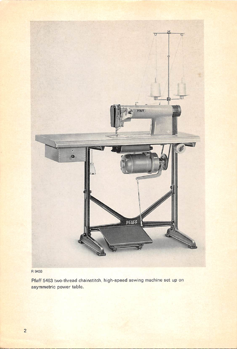
R9430
Pfaff 5463 two-thread chainstitch, high-speed sewing machine
asymmetric
power
table.
set
up on
Page 3
1.
General
The
which
new
makes
Pfaff
5463isa
the
two-thread
flat-bed
high-speed
chainstitch.U.S.
sewing
Federal
machine
Stitch
Type
fitted
withatransverse
401.
iooper
Equipped
built
size.
The
two-thread
regulator.Inaddition,itis
needle
6,000
For the time being, the machine is available in two varieties:
The
of two-thread chainstitching.
The
duces two lines of two-thread chainstitching, using four threads.
Thelatter
6.4
2.
Insert
as it
screw
with
ordinary
into
the
Pfaff
463
essential
difference
chainstitch
bar
and
replaces
s.p.m.and makes up to
Pfaff
5463-801isequipped
Pfaff
5463-802,
varietyisavailable
mm.
Inserting
the
needle
will
go.
securely.
the
into
Turn
on the other
Needle
it so that its
drop
feed,
this
machine
and
closely
resembles
between
sewing
the
the
both
machines
mechanism
fitted
withathread
conventional
5V2
stitches to the
with
one
hand,isfitted
at present in needle gauges of about
opening
ofthe
long
groove faces
follows
this
liesinthefact
andadisc-type
take-up
link
take-up.
inch.
needle
and
with
needle
bar or
the
latter
machineinits
lever
The
Ituses
one
two
needles
needle
toward
Pfaff
Iooper
same
basic
mechanical
exterior
that
the
Pfaff
rather
thanalink-type
whichisrigidly
5463
attainsatop
4463kKneedles.
and
producesasingle
and
two
Vw"
and
holder
and
you and
tighten
principle
design
5463
features
mounted
speed
loopers
pushitup
and pro
V4",
or 4.8 and
the needle set
and
a
feed
onthe
of
line
as far
3.
Adjusting
The needle bar frame should be positioned so that the needle
close
to its
To adjust the position of the needle bar frame in the direction of sewing, turn the eccentric
studatthe
Ifthe position of the needle bar frame requires adjustment crosswise of the direction of sew
ings, push it to the right or left in its bearings, as appropriate.
the
Needle
near
end, without actually touching it.
needle-bar-endofthe
Bar
machine
Frame
withascrewdriver.
will
enter the needle plate slot
Page 4

4.
Adjusting
The
lobeofthe
top
of its
point
down
the
feed
stroke.
At the
perpendicularly.
Feed
lifting
same
Dog
eccentric
time,
the
should
borehole
pointupwhen
in the
balancing
the
needle
collarofthe
bar
has
reached
eccentric
the
should
When the feed dog is at its highest point, its teeth should protrude from the surface of
the
needle
platebyabout
,or1.2 mm.
Timethe feed dog so that it
risen
clearofthe
4.1 Timing
To time
the
the
feed
needle
Feed
motion,
shaft, as may be appropriate (Fig. 1). If the feed
this guide backward; if it is supposed to begin earlier,
Motion
will
start to advance the material right after the needle point has
plate
slot.
loosen
set
screws
a in
the
dovetail
motion
guide
and turn
is supposed to begin later, turn
forward,
i.e. toward you. After this
this
guide
on its
adjustment, tighten set screws a securely. Anyretiming of the feed motion necessitates a re
timing of the looper motion in relation to the needle stroke.
4.2
Setting
the
Loopertothe
To do this, turn the balance wheel toward you
line of the needle as the looper moves toward the
of the
looper
point
and the edge of the
posite
direction
make
sure the
If
adjustmentisrequired,
regulator,asmay
Fig. 1
until
relative
be appropriate.
the
looper
vertical
Needle
pointisagain
positions
loosen
Then
until
needle
eye.
opposite
of the looper
set
screwsb(Fig.1)and
tighten
set screws b securely.
the looper point is opposite the center
left.
Note the relative vertical positions
Then
turn
the
balance
the
center
point
and the needle eye are the same.
rotate
wheelinthe op
lineofthe
the
gearonthe
needle
feed
and
s
a
;
i2
/
/
a =
Set
screws
on dovetail
b =
Set
a
screwsongear
guide
Page 5
5. Adjusting and
5.1 Setting the Looper at the Correct Height
The looper
face
5.2
with
Setting
should
the
the
thread
Timing
the Looper
be set so that its underside rests on the
grooveispositionedatright
Looper
Point
in Relation to
the
angles
Center
to the
Line of
looper
sewing
the
Needle
holder
and its inner sur
direction.
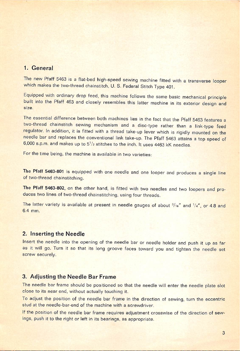
When the descending needle reaches the lowest point of its stroke, the looper should be
at the extreme right of its stroke. When the looper is at this position, there should be a
''U*",
or 3.6
rnm,
clearance of about
(Fig. 2).
between its point and the center line of the needle
Ifadjustment is required, loosen clamping screw d (Fig. 3) and. with the aid of wrench SW 6,
turn eccentric ball stud c (Fig. 2) which connects the looper holder with the driving rod. as
may be required. After this adjustment, tighten the set screw securely.
Fig. 2
c =
Eccentric
ball
stud
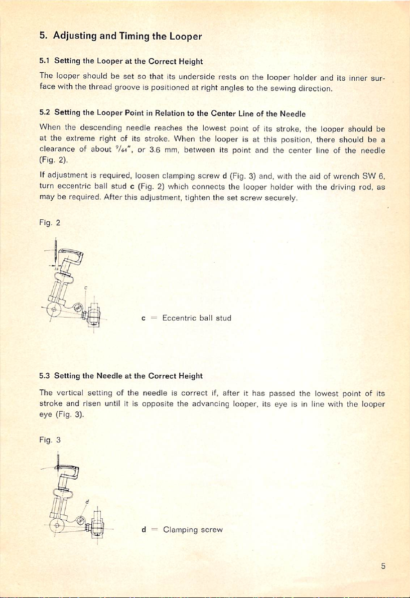
5.3
Setting
the
Needleatthe
The vertical setting of the
stroke
and risen until it is
eye
(Fig. 3).
Fig. 3
Correct
needleiscorrect
opposite
Height
the advancing looper, its eye is in line with the looper
Clamping
if,
screw
afterithas
passed
the lowest point of its
Page 6

5.4 Timing
the
Looper
Avoiding Motion
The looper avoiding motion is controlled by an eccentric which is carried on the main drive
shaft
under
the
bedplate.
Eccentric e (Fig. 4) is
front
set
screw
set
correctly if its lobe points to the right toward the needle and its
f points downward when the needle has reached the bottom of its stroke (g in
Fig- 4).
Fig. 4
e =
Eccentric
f =
g =
5.5
Setting
the
Turn
the
to
see
to
turn
between
the
looper
Loopertothe
balance
that
the
looper
wheel
the looper is at the extreme right of its stroke. If this setting is correct, continue
balance
point and
must
not
strike
NeedleinSewing
until
wheel
until
needle
the
needleihas
the
should
needle
If adjustment is required, loosen both
turn
this
bracket
around
its
fulcrum
until
looper is obtained. Then tighten both
Eccentric
Needleatlowest
looper
(Fig. 5).
set
the
set
screws I securely again (Fig. 5).
front
set
screw
point
Direction
reached
not
the
lowest
pointisopposite
exceed
.004",or0.1 mm. On the
point
the
of its
needle.
stroke
The
and
clearance
other
screws I on the looper mechanism bracket and
correct
amountofclearance
between
needle
check
hand,
and
Fig. 5
h =
1 =
k =
I =
Fulcrum
Needle
Bracket
Bracket
stud
set
screws
Page 7

6. Adjusting the Looper Thread Pull-Off Lever
Thread pull-off lever m is clamped onto a stud on the looper driving rod and should be ad
^U*",
justed so that there is a clearance of about
avoiding motion
of its throw (Fig. 6).
eccentric
and
Fig. 6
m =
n =
the
thread
Looper
Set
collar
thread
pull-off
or 2.0 mm, between collar n of the looper
lever
when
the
latter
is at
the
extreme
pull-off
lever
left
7. Regulating
The thread regulator arranged under
regulating
plate.
the
Looper Thread Pull-Off
the
bedplate
consists
of a bracket and an adjustable
Regulating plate o can be adjusted on its bracket and determines the amount of thread
tobepulled
over
from you (Fig. 7).
Any adjustment of the thread pull-off lever in relation to the regulating plate
off. To
increase
this
amount,
move
the
plate
toward
you,
andtodecrease
changes
the
time at which the thread is pulled through the looper thread tension. If the thread pull-off
lever
has
been
adjusted,
The regulating plate should be
thread
will be pulled
needleisat
When
the
other
automatically.
the
the
needle
phasesofthe
top
taut
of its
enters
regulating
the
stroke.
the
plateohas
set
in relation to the thread pull-off lever so that the looper
very
moment
thread
triangle,
the
to be
looper
the
adjusted
thread
begins
should
likewise.
its
return
become
stroke,
slack
i.e.
again. During
stitch forming cycle, the tension on the looper thread will be regulated
when
the
The curvature of the regulating plate controls the looper thread so that it will not be too slack
when the looper swings forward to pick up the needle thread, and
under
the
topofthe
looper.
Fig. 7
that
it will not be flung
it,
Regulating
plate
Page 8

8.
Adjusting
Thread
eyelet will be positioned about
the
needle
The
adjustable
regulator
bar
the
Needle
r (Fig. 8) on
is at its
thread
lowest
guide
Thread
the
tension
Va",
or 3.0 mm. below the top of the thread regulator when
point
(see
s (Fig. 8) on
Regulator
bracket
g in Fig. 8).
the
tension
that the thread runs in a horizontal line from its top
bar
needle
and
9.
Is at the top of its stroke. This setting should be
thread
being
used
(see
p in Fig. 8).
p =
Positionoftake-up
with
q =
Positionoftakeuplever
with
r =
Thread
s —
Adjustable
Adjusting
the
Looper
Swing-Back
needle
needle
Guide
shouldbesetsothat
bracket
shouldbeadjusted
edge
to the take-up lever eyelet when the
adapted
lever
barattopofstroke
baratbottomofstroke
regulator
thread
guide
the
take-up
to the type of material
eyelet
eyelet
vertically
lever
so
Looper swing-back guide u (Fig. 9) should besoadjusted that the looper
distanceof0.1or
When
looper
the spring-loaded
0.3 mm (Fig. 9).
t is at
the
base
extreme
right of its
stroke,itcanbeswung
catch (Fig. 9). With the looper swung out. Its
base
clears
outbypressing
base
should
bear
it at a
against
against
the swing-back guide so that the thread eyelet near its point clears the edge of the needle
plate on the right and the looper can be threaded without any difficulty (see Fig.14on page 12).
When
sewingisresumed,
Fig. 9
1
the
looper
t =
u =
returns
Looper
Looper
to its
operative
swing-back
position automatically.
guide
Page 9

10.
Adjusting
The rigid
it lightly,
To
guard
looperisopposite
the
proper
After this adjustment, tighten
Fig. 10
however
adjust
around
needle guard. In adjusting the needle guard, make
timing of
the
Needle
needle
guard w should be so adjusted that the
without
the
positionofthe
its fulcrum,asmay be
the
needle
the
loop
Guard
being
needle
on its
spreading
set
deflected
guard
reverse
action.
screwvsecurely
V =
w =
(Fig. 10).
vertically,
required
Needle
Needle
(Fig. 10).
side,
guard
guard
the
again.
descending
loosen
When
needle
sureitdoes
set
screw
needle
will chafe
set
screwvand
the
point of
shouldbeoutofcontact
turn
the
not interfere with the
against
the
needle
advancing
with
11. Regulating
the
Stitch Length
To regulate the stitch length, depress button x on the bedplate and turn the balance wheel
until this button
wheel
backorforth until
The stitch length
Fig. 11
snapsinplace
the
set
is indicated on scale y in the belt guard window (Fig. 11).
(Fig. 11). While keeping it
desired
stitch length
has
been
X =
y = Stitch
set.
Needle
depressed,
position
length
rotate the balance
knob
scale
Page 10

12.
Threading
upper
threading
Lead
the
thread
thread guide 2 on the machine arm.
guide3,clockwise
the
Needle
is illustrated In Fig. 12.
from
spool
1 up to
around
and
between
the
top
thread
guideofthe
Pass
it through the holes of this guide and of thread
tension
discs4and
through
thread
the
stand
center
and
down
holeofadjust
able thread guide 5. Passing above adjustable thread regulator 5a, the thread is then led
from right to left through the hole in take-up lever 6 which moves up and down with the
pass
needle bar. Then lead the thread down through guides 7, 8 and 9 and
back
through
the
eyeofneedle
10.
it from front to
to
10
Fig. 12
R943I
Page 11

13.
Threading
Pass
the thread from spool 11 on the thread
down
through
through hole 15 and thread guide 16 on the arm standard. Swing out thread guide z, insert the
thread into thread guide 17 near its lower end, and swing the guide back to its original posi
tion. Next, pull
the
Looper
holes12and
the
thread
into
13,
thread
clockwise
channel 18 In
stand
around
up and through the top thread guide and
and
the
between
bedplate,
tension
starting
discs
14.
at the arm
down
standard,
and
and draw it through thread guide 19, hole 20 of the thread pull-off lever, opening 21 of the
thread regulator, hole 22 of the thread pull-off lever, hole 23 at the heel of the looper and
then from front to back through hole 24 at the looper point.
Fig. 13
r;
R9432
11
Page 12

cm
Fig. 14
To draw the looper thread through guides 19 through 24, remove the right bedplate cover
by pulling back slide S (Fig. 12). Turn the
balance
wheel until holes 20 and 22 near the tips
R
9435
of the thread pull-off lever are in line with opening 21 of the thread regulator and the thread
can
be pulled from thread guide 19 through holes 20, 21 and 22.
To thread the looper, rotate the balance wheel until the looper is in its extreme right position.
Then swing out the looper by pressing against release latch k (Fig.14)with your finger.
12
Page 13

Contents
1.
General
2. Inserting the Needle
3. Adjusting
the
Needle
Bar
Frame
4. Adjusting the Feed Dod
4.1 Timing
4.2 Setting the Looper to
the
Feed Motion
the
Needle
5. Adjusting and Timing the Looper
5.1 Setting the Looper at the Correct Height
5.2 Setting the Looper Point inRelation to the Center Lineof the Needle
5.3 Setting the Needle at the Correct Height
5.4 Timing the Looper Avoiding Motion
5.5 Setting the Looper to the Needle in Sewing Direction
6. Adjusting the Looper Thread Pull-Off Lever
7.
Regulating
the LooperThread
Pull-Off
•
8. Adjusting the Needle Thread Regulator .
9.
Adjusting
the Looper
Swing-Back
Guide
10. Adjusting the Needle Guard
11. Regulating the Stitch Length
12.
13.
Threading
Threading
the
the
Needle
Looper
3
3
3
4
4
4
5
5
5
5
6
6
7
7
8
8
9
9
10
11
13
Page 14

mr
No. 12321
engl.
R 366
PrintedinGermany
 Loading...