

Page 1
Service
Manual
PFAFF
INDUSTRIEMASCHINEN
GMBH
KAISERSLAUTERN
Page 2
Instructions
for
adjusting
the
Pfaff 487
Important
note
Never use a C-clamp on the needle bar of Pfaff 480
would
damage
On machines which
its
special
coating.
are
put into operation for the first time or which have been idle
series
machines
because
this
for a longer period of time(1or 2 months) make absolutely sure to check the hook
lubrication
Important
All
adjustments described In this book also apply to version N machines (6.0 mm maximum ~ -
stitch length). An exception
knurled
Ifonthese
Is
set
at "0", all adjustments which are carried out with the stitch length
be
made
note
all
with
system
for
versionNmachines
the
way
around.
machines
the
reverse-feed
(Section
the
reverse-feed
14).
are
machines supplied earlier whose stitch length control Is
control
control
depressed.
canbemoved
when
the
stitch
length
set
at "0" must
control
If on machines having a stitch length control which Is knurled all the way around the
reverse-feed control
the stitch length
reverse-feed
control
cannot
set
at "0" must be
depressed.
be moved, all
made
adjustments
which have to be
with the stitch length
carried
set
at "1.5" and the
out
with
Tools,
gauges
1
setofscrewdrivers
1
setofspanners
1
22-mm
1
setofalien
1
metal
1
adjusting
1
gauge.
(gauge
1
wrapper
1
stripofwhite
and
other
equipment
with
blades
from2to10mm
from7to
spanner
keys
ranging
rule
pin, 5 mm dia.. No. 13-030 341-05
No. 61-111
foot
with
642-19
No. 61-111 639-20)
System
paper,
134
sewing
14 mm
from
needles
thread
1.5
needed
wide
to 6.0 mm
and
for
adjusting
material
wide
for
the
testing
Pfaff 487:
purposes.
Page 3
1
1.1
Preparations
Take
out
for
both
screwsofthe
adjustment
face
cover
and
remove
the
cover.
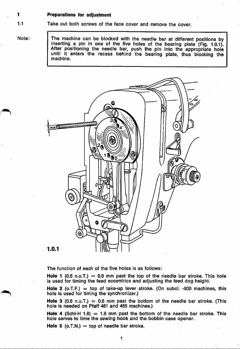
Note:
The rnachlne can be blocked with the needle bar at different positions by
inserting a pin in one of the five holes of the bearing plate (Fig.
1.0.1).
After positioning the needie bar, push the pin into the appropriate hole
untii it enters the recess behind the bearing plate, thus blocking the
machine.
The
functionofeachofthe
Hole
1 (0.6 n.o.T.) = 0.6 mm
is
used
for
timing
the
Hole
2 (o.T.F.) =
holeIsused
Hole
3 (0.6 n.u.T.) = 0.6 mm
for
timing
topoftake-up
holeisneededonPfaff 481
Hole
4 (Schl-H 1.8) =
hole
servestotime
Hole
5 (o.T.N.) =
the
topofneedle
five
feed
eccentrics
the
synchronizer.)
and
1.8
mm
sewing
holesisas
past
the
lever
past
the
485
machines.)
past
the
hook
and
bar
stroke.
1
follows:
topofthe
and
adjusting
stroke.
bottomofthe
bottomofthe
the
bobbin
(On
needle
the
subcl.
case
bar
feed
needle
needle
opener.
dog
-900
stroke.
height.
machines,
bar
bar
This
stroke.
stroke.
hole
this
(This
This
Page 4
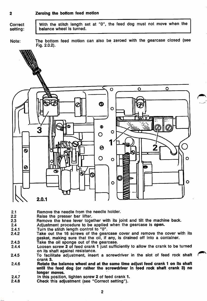
Zeroing
the
bottom
feed
motion
Correct
setting:
Note:
With the stitch length
balance
The
Fig. 2.0.2).
wheelIsturned.
bottom
feed
motion
set
at "0", the feed dog must not move when the
can
alsobezeroed
with
the
gearcase
1
closed
(see
2.1
2.2
2.3
2.4
2.4.1
2.4.2
2.4.3
2.4.4
2.4.5
2.4.6
2.4.7
2.4.8
Remove
Raise
Remove
Adjustment
Turn
Take
gasket,
Take
Loosen
on
To
crank
Rotate
until
longer
In
Check
the
needle
the
presser
the
knee
proceduretobe
the
stitch
out
the16screwsofthe
making
the
oil
sponge
screw
Its
shaft
3.
the
the
moves.
position,
this
against
adjustment.
balance
feed
adjustment
facilitate
this
length
sure
2 of
dog
tighten
bar
lever
feed
from
the
needle
lifter.
together
controlto"0".
with Its
applied
holder.
when
gearcase
that
the
outofthe
resistance.
oil, If any, Is
gearcase.
crank1just
sufficiently to allow
InsertascrewdriverInthe
wheel
(or
andatthe
rather
screw
(see
"Correct
same
the
screwdriverinfeed
2 of
feed
setting").
joint
and
the
gearcaseIsopen.
cover
drained
time
crank
1.
tilt
the
machine
and
remove
the
off into a container.
the
cranktobe
slotoffeed
adjust
feed
crank1on
rock
shaft
cover
crank
back.
rock
its
with Its
turned
shaft
shaft
3) no
Page 5
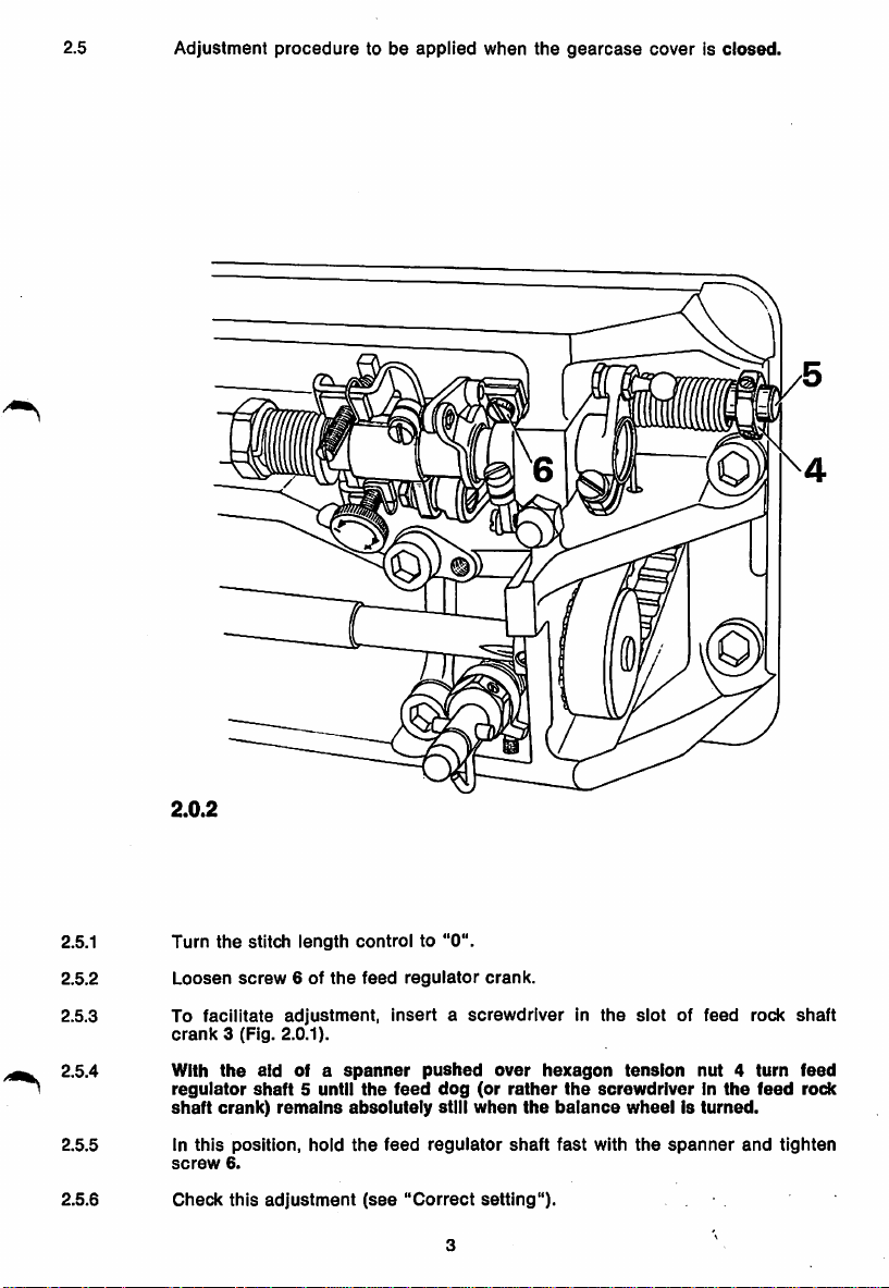
2.5
Adjustment
proceduretobe
applied
when
the
gearcase
coverIsclosed.
2.0.2
2.5.1
2.5.2
2.5.3 To
2.5.4 With
2.5.5 In
2.5.6
Turn
the
Loosen
facilitate
crank
the
regulator
shaft
crank)
this
screw
Check
stitch
length
screw
6 of
adjustment,
3 (Fig. 2.0.1).
aid
of a
shaft5until
remains
position,
6.
this
hold
adjustment
controlto"0".
the
feed
regulator
InsertascrewdriverInthe
spanner
absolutely
the
the
(see
feed
feed
"Correct
pushed
dog
still
regulator
3
(or
when
setting").
crank.
over
rather
shaft
hexagon
the
slotoffeed
tension
the
screwdriverInthe
balance
fast
wheelIsturned.
with
the
nut4turn
spanner
rock
and
feed
tighten
shaft
feed
rock
Page 6
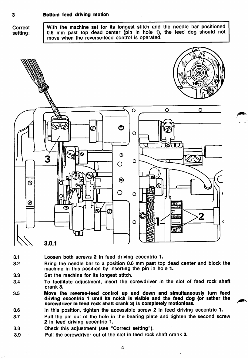
Bottom
feed
driving
motion
Correct
With
setting: 0.6
move
the
machine
mm
past top dead center
when
the
reverse-feed
set
m
for its
longest
(pin
controlisoperated.
stitch
and
the
needle
bar
positioned
in hole 1), the feed dog should not
3.1
3.2 Bring
3.3
3.4 To facilitate
3.5 Move
3.6 In this position, tighten
3.7 Pull
3.8
3.9
Loosen
machineinthis
Set
the
both
the
machine
screws
needle
positionbyinserting
adjustment,
crank
3.
the
driving
screwdriverinfeed
2 in
Check
Pull
eccentric
the
feed
this
the
reverse-feed
pin
outofthe
driving
adjustment
screwdriver
2 in
feed
bar
to a position 0.6 mm
for
its
longest
insert
control
1 until its
rock
notchIsvisible
shaft
crank
the
accessible
hole in
eccentric
(see
outofthe
1.
"Correct
driving
eccentric
the
stitch.
the
screwdriverinthe
up
and
3) is
compieteiy
screw
the
bearing
setting").
slotinfeed
past
pin in
down
plate
rock
and
2 in
1.
top
dead
hole
1.
and
simultaneously
the
motionless.
feed
and
tighten
shaft
crank
center
slot
feed
driving
3.
and
of feed rock
(or
turn
rather
dog
eccentric
the
second
block
shaft
1.
screw
the
feed
the
Page 7
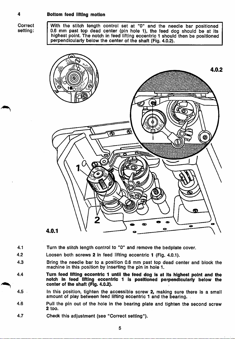
Bottom
feed
lifting motion
Correct
setting:
With the stitch length control
0.6 mm
past
top
dead
center
set
(pin hole 1), the feed dog shouldbeat Its
highest point. The notch in feed lifting
perpendicularly
below
the
centerofthe
at "0" and the needle bar positioned
eccentric
shaft
1 should then be positioned
(Fig. 4.0.2).
4.0.2
4.1
4.2
4.3 Bring
4.4 Turn feed lifting
4.5 In this position, tighten
4.6 Pull
4.7 Check this
Turn
the
stitch
Loosen
machineinthis
notch in
centerofthe
amount
2
too.
the
both
the
of play
pin
needle
feed
outofthe
adjustment
length
control
screws
2 In
feed
bar
to a
positionbyinserting
eccentric
lifting
shaft
(Fig. 4.0.2).
position
1 until the feed dog is at its highest point
eccentric
the
between
feed
hole in
(see
"Correct
to "0"
and
lifting
0.6 mm
the
1 is
accessible
lifting
eccentric1and
the
bearing
remove
eccentric
pin in
positioned
screw
plate
setting").
the
1 (Fig. 4.0.1).
past
top
hole
2, making
and
bedplate
dead
1.
cover.
center
perpendicularly
sure
the
tighten
there
bearing.
the
and
below
is a smali
second
block
and
the
the
the
screw
Page 8
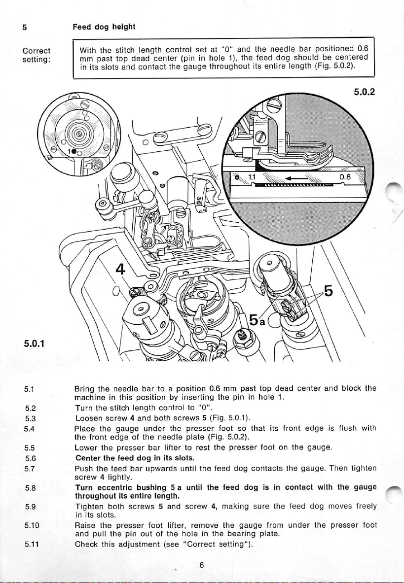
Feed
dog
height
With the stitch length control
set
at "0" and the needle bar positioned 0.6
mm past lop dead center (pin in hole 1), the feed dog should be centered
in its slots and
contact
the
gauge
throughout its entire length (Fig. 5.0.2).
Bring the needle bar to a position 0.6 mm
machineinthis
Turn
the
Loosen
screw4and
Place
the
the
front
Lower
the
Center
the
Push
the
screw4lightly.
Turn
eccentric
throughout
Tighten
in
its
slots.
Raise
the
and
pull
Check
this
positionbyinserting
stitch
length
gauge
presser
feed
bar
under
dogInits
upwards
edgeofthe
feed
bushing
Its
entire
both
screws5and
presser
the
pin
outofthe
adjustment
controlto"0".
both
screws
the
needle
bar
liftertorest
slots.
until
5 a until
length.
screw4,making
foot lifter,
(see
holeinthe
"Correct
5 (Fig. 5.0.1).
presser
plate
(Fig.
the
the
remove
past
the
pin in
footsothat
5.0.2).
the
presser
feed
dog
feed
dog
the
gauge
bearing
setting").
top
dead
hole
its
footonthe
contacts
Is In
sure
the
from
plate.
1.
front
the
contact
feed
under
center
and block the
edgeisflush
gauge.
gauge.
Then
with
dog
moves
the
presser
the
tighten
gauge
freely
with
foot
Page 9
6
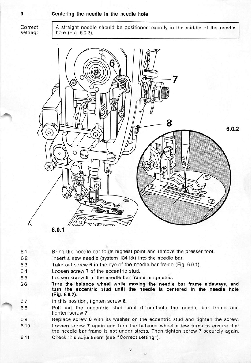
Centering
the
needleInthe
needle
hole
Correct
setting:
A
straight
hole
needle
(Fig. 6.0.2).
i
shouldbepositioned
i
8
i
exactlyInthe
middle of
the
needle
Bring
the
needle
bar
to its
Insertanew
Take
out
Loosen
Loosen
Turn
turn
(Fig. 6.0.2).
In
Pull
tighten
Replace
Loosen
the
Check
screw7of
screw
the
the
this
position,
out
screw
screw7again
needle
this
screw6with
needle
screw
8 of
balance
eccentric
the
eccentric
7.
bar
frameisnot
adjustment
6 in
the
the
the
wheel
tighten
(system
eyeofthe
eccentric
needle
stud
screw
its
and
(see
highest
while
until
stud
washer
point
134 kk) into
needle
stud.
bar
frame
moving
the
8.
until
on
turn
the
under
stress.
"Correct
and
the
bar
hinge
the
needle
it
contacts
the
eccentric
balance
Then
setting").
remove
needle
the
bar.
frame
(Fig.
stud.
needle
is
bar
centered
the
stud
wheelafew
tighten
presser
needle
and
screw7securely
foot.
6.0.1).
frame
sideways,
In
the
needle
bar
tighten
turnstoensure
frame
the
and
hole
and
screw.
that
again.
Page 10
Correct
setting:
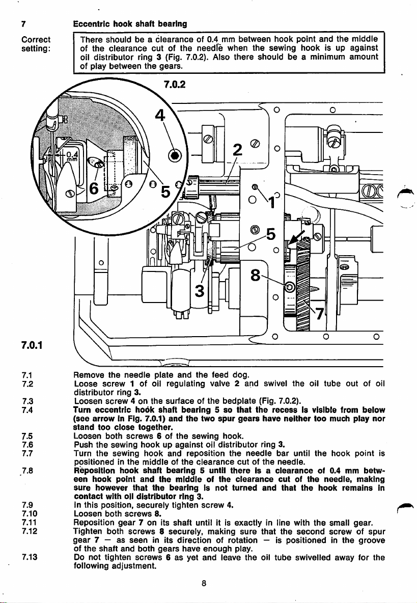
Eccentric
There
of
the
oil
distributor
of
play
hook
shaft
shouldbea
clearance
ring 3 (Fig. 7.0.2). Also
between
bearing
clearance
cutofthe
the
gears.
of 0.4 mm
needle
between
hook
point
and
the
when the sewing hook is up
there
shouldbea minimum
middle
against
amount
7.0.1
7.1
7.2
7.3
7.4
7.5
7.6
7.7
7.8
7.9
7.10
7.11
7.12
7.13
Remove
Loose
distributor
Loosen
Turn
(see
stand
Loosen
Push
Turn
positionedinthe
Reposition
een
sure
contact
In
Loosen
Reposition
Tighten
gear
of
Do
following
the
screw
ring 3.
screw4on
eccentric
arrowInFig.
too
close
both
the
sewing
the
sewing
hook
point
however
with
this
position,
both
both
7 —asseen
the
shaft
not
tighten
adjustment.
needle
screws
hook
oil
screws
gear
and
plate
1 of oil
hook
7.0.1)
together.
and
regulating
the
surfaceofthe
shaft
and
6 of
the
bearing5so
the
sewing
hookupagainst
hook
and
middleofthe
shaft
and
that
the
distributor
securely
8.
7 on its
reposition
bearing5until
the
middleofthe
bearingIsnot
ring
tighten
shaft
screws8securely,
in its
both
screws6as
directionofrotation
gears
have
yet
the
feed
valve2and
two
spur
oil
distributor
clearance
3.
screw
until it is
making
enough
and
leave
dog.
bedplate
that
gears
hook.
the
cutofthe
there
clearance
turned
4.
exactly
sure
play.
swivel
(Fig. 7.0.2).
the
recessIsvisible
have
ring 3.
needle
Is a
and
in line with
that
— is
the
oil
-Q
the
oil
neither
too
bar
until
the
the
of 0.4
hook
needle.
clearance
cutofthe
that
the
the
second
positionedinthe
tube
swivelled
rmirn
m
tube
out
of oil
from
mm
remains
away
below
play
point
betw
making
gear.
groove
for
much
hook
needle,
small
screwofspur
nor
is
In
the
8
Page 11
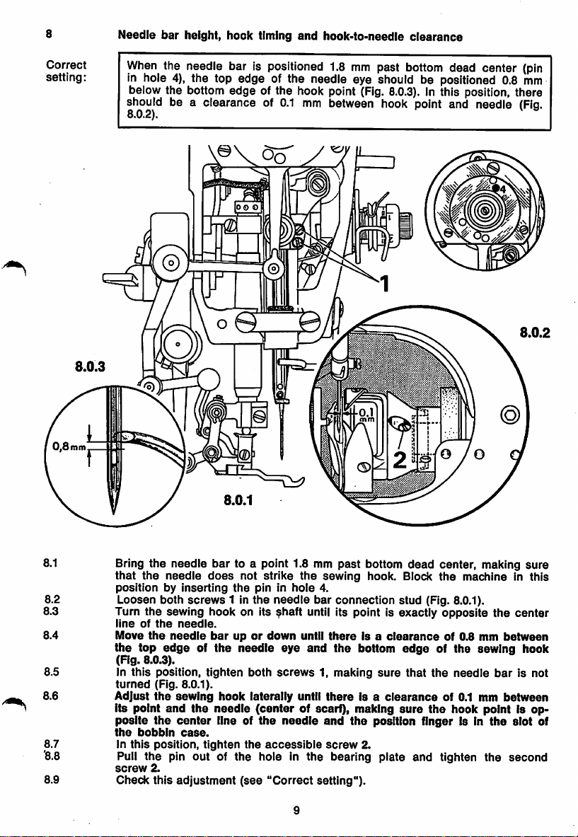
Needle
bar
height,
hook
timing
and
hook-to-needie
clearance
Correct
setting:
When
the needle bar is positioned 1.8
mm
past
bottom
dead center
in hole 4), the top edge of the needle eye should be positioned 0.8
below the bottom edge of the hook point
should be a clearance of
8.0.2).
0.1
mm
(Fig.
8.0.3).
In this position, there
between hook point and needle
s
oo
o
(pin
mm
(Fig.
8.0.2
8.1 Bring the needle
that
the
positionbyinserting
needle
8.2 Loosen both
8.3 Turn
8.4 Move
8.5 In
8.6
8.7 In
'8.8
8.9
the
lineofthe
the
(Fig. 8.0.3).
turned
Adjust
its point
posite
the
sewing hook on its ^haft until its point is exactly opposite
the
needle
top
edgeofthe
this
position,
(Fig. 8.0.1).
the
and
the
bobbin
this
position,
Pull the pin out of the hole in the bearing plate and tighten the second
screw
2.
Check
this
bar
does
screws
needle.
barupor
tighten
sewing
hook
the
needle
center
line of
case.
tighten
adjustment
to a point 1.8 mm
not
strike
the
1 in
needle
(see
pin in
the
both
laterally
(center
the
hole
needle
down
eye
screws
the
needle
accessible
"Correct
until
9
the
until
and
of scarf), making
past
sewing
4.
bar
connection
there
the
1, making
there
and
the
screw
setting").
bottom
dead
hook. Block
Is a
clearance
bottom
sure
is a
clearance
center, making
the
stud
(Fig. 8.0.1).
edge
of the sewing hook
that
the
sure
the
position finger Is In
2.
machineInthis
the
of 0.8 mm
needle
of 0.1 mm
between
bar
between
hook point Is op
the
slot
sure
center
is not
of
Page 12

Eccentric
bobbin
case
opener
shaft
bushing
Correct
setting:
When at Its left point of reversal, bobbin
case
opener finger 3 should be
positioned vertically so that it Is exactly opposite the lug of bobbin case
base
4 (Fig. 9.0.2).
9.0.1
9.1
9.2
9.3
9.5
Loosen
Turn
Turn bushing 2 until
case
from
9.4
Check
screw
1 of
eccentric
the
balance
base
the
sewing
In
this
position,
this
wheel to bring
4. (Fig. 9.0.2). Make
hook.
tighten
adjustment
opener
screw
(see
bobbin
case
opener
shaft
the
opener
finger to Its left point of reversal.
finger 3 is exactly opposite
sure
1.
"Correct
10
the bobbin
setting").
case
bushing
can
2 (Fig. 9.0.1).
the
lug of bobbin
be easily removed
Page 13

10
Position of
bobbin
case
opener
Correct
setting:
There
should
finger 1 and
the
left of its stroke,
bobbin
case base 5
there
should be a
bobbin case base 5 and position finger 6
be a clearance of abt. 0.8
(Fig.
mm
10.0.2).
clearance
(Fig.
between
When
bobbin
opener finger 1 is on
of abt. 0.3 mm between
10.0.3),
In this position, the
lug on collar 4 should be up against the stop ofopenerfinger1
10.0.1
case opener
(Fig.
10.0.1).
0.3
mm
10.1
10.2
10.3
10.4
10.5
10.6
10.7
10.8
10.9
10.0.2
Loosen
Loosen
turned
Reposition
screw3of
clamp
on
its
opener
betweenitand
Rotate
the
balance
Turn
opener
position
base
In
Push
against
In
Check
when
this
position,
collar 4 up
the
this
position,
this
finger6and
opener
stopofopener
adjustment
screw
shaft
bobbin
finger
securely
tighten
collar
4.
2 of
against
finger1on
case
wheel
until
1 untii
the
finger 1
against
right
contacts
tighten
opener
finger
screw
(see
opener
resistance.
its
base
opener
there
waiiofthe
screw
1.
3.
"Correct
11
finger 1
shaft
just
untii
5 (Fig. 10.0.2).
finger
1 isonthe
is a
thread
the
finger 1
position
iug of
2.
and
setting").
sufficiently to allow it to be
thereisa
ciearance
bobbin
clearance
left of its
of 0.3 mm
slotinthe
case
base
turn itsothat its iug is up
10.0.3
of
0.8
stroke.
between
bobbin
5 (Fig. 10.0.3).
mm
case
Page 14

Timing
Ihe
bobbin
case
opener
When the needle bar is positioned 1.8 mm past bottom dead center (pin
in hole 4), opener finger 3 should be at its right point of reversal (Fig.
11.0.2).
11.0.2
.s
h"!
lA'-
. V
11.0.1
Loosen
Bring the needle bar to a point 1.8 mm past bottom
the
To
driverinthe
Turn
(Fig. 11.0.2).
in this position, tighten the
11.0.1), making
the
Puii the pin out of the hole In the bearing plate and tighten the
screw
Pull
"Correct
booth
screws
machineinthis
facilitate
opener
determining
slotofthe
eccentric
sure
lifting
eccentric.
2
also.
the
screwdriver
setting").
2 (Fig. 11.0.1).
positionbyinserting
the
exact
clampofopener
1 until
opener
accessible
the
pin in
pointofreversal
finger
3.
finger 3 Is at Its right point of reversal
screw
2 of
there is sufficient play between
outofthe
clamp
slot
and
dead
hole
4.
insertasmall
opener
opener
check
this
center
eccentric
eccentric
adjustment
and block
screw
1 (Fig.
1 and
second
(see
Page 15

12
Oil
tube
In oil
distributor
ring
Correct
setting;
Oil
tube
12.0.2).
1 should be positioned In the hole of oil distributor ring 2 (Fig.
12.0.2
gnnr
12.0.1
12.1
Note:
12.2
Insert
oil
12.0.2); If
On
subcl.
have
loosened
Tighten
tube
1 Into
the
hole
necessary,
-900
screw
turn oil distributor ring 2 accordingly.
machines
the
three
screwsonthe
3 of oil regulating valve 4 (Fig. 12.0.1).
of oil distributor ring 2
the
oil
distributor
13
front
ring
cannot
sideofthe
(see
be
hook
arrow
turned
shaft
In Fig.
until you
bearing.
Page 16

13
Correct
setting;
Oil
check
valve
There
should
beaclearance
of 1.0 mm
between
actuating
rod
3 of
centrifugal governor and push rod 4 of the oil check valve (Fig. 13.0.2).
13.0.2
the
13.0.1
13.1
13.2
13.3
13.4
13.5 In
13.6
13.7
13.8
13.9
Loosen
Push
Press
screw
actuating
push
Reposition
actuating
this
position,
Check
this
Soak
the
recessisat
Clean
the
Replace
legs,
the
tightening
1 of oil
check
rod 3 Into
valve
the
2 (Fig. 13.0.1).
centrifugal
rod 4 Into oil check valve 2 until a
oil
check
rod3and
tighten
adjustment
oil
sponge
the
bottom
gasket
gearcase
the
valve 2 until
push
rod
screw
(see
with oil
left
faceonthe
cover
screwsofthe
there
4 (Fig. 13.0.2).
1.
"Correct
and
and
replace
the
setting").
oil
gearcase
and
simultaneously
cover
14
tubeisplaced
and
crosswise.
governor.
Is a
It In
the
noticeable
clearance
the
gearcasesothat
on
gasketofthe
screwonthe
resistance
of 1.0 mm
top
of It.
gearcase
two machine
Is felt.
between
Its
large
cover.
Page 17

14
Hook
lubrication
Correct
setting:
After
the
machine
of oil should
cutout
above
appear
the
hook
has
run at full
on a piece of
raceway.
speed
for
about
ten
paper
placed over the needle plate
seconds,
a fine
trace
14
14.1
14.2
14.3
14.4
14.5
14.6
14.7
14.8 If
14.9
Check
the
is in
line
with
Turninregulating
then
back
about
Start
the
machine
Turn
regulating
Let
the
machine
oil level
and,ifnecessary,
the
upper
screw
three
and
screw
run
Placeapieceofwhite
Let
the
oil
has
too
Is
emitted,
Check
machine
appeared
much
this
run
on
oil Is
emitted,
turnItout
adjustment
mark.
1 of oil
turns.
run it until
1 in
completely
about1minute.
paper
over
about
ten
paper
turn
"Correct
seconds.
opposite
regulating
15
the
somewhat.
(see
topupthe
Use
oil No.
regulating
the
the
needle
setting").
reservoir
280-1-120144.
valve 2asfarasit will go,
sewing
and
Then
the
screw
hook
then
out
plate
checktosee
hook
1 in a
starts
halfaturn.
cutout.
raceway.
little;orIf
until
emitting
if a
the
fine
oil level
oil.
trace
too
and
of
little oil
Page 18

15
Zeroing
To
15.5
the
top
determine
mustbecarried
feed
whether
motion
the
out
first.
following
settingIscorrect,
adjustments
15.1 to
Correct
setting:
(S)
With
move
the
when
stitch
the
i
length
balance
lllil
setat"0",
wheelIsturned.
feed
driving
lever
7 (Fig. 15.0.4)
must
Q
o
not
15.0.1
Turn
15.1
15.2
15.3
15.4
15.5
regulating
Turn
out
Set
the
Its
upper
Turninregulating
downwards.
Turn
regulating
screw1outafew
stop
screw
machine
position.
screw1back
2 until a
for
screw
Its
resistance
longest
1 until
halfaturn.
16
turns.
stitch
the
Is felt.
and
move
reverse-feed
the
reverse-feed
control
begins
control
to
move
to
Page 19

Not©:
For information on version N machines supplied earlier
15.0.2
m/
liiiiii
see
inside front cover.
15.6
15.7
15.8
15.9
15.10
15.11
15.12
15.13
15.0.3
Turn
the
stitch
Adjust
scale4so
Retain
the
scaieinthis
Repiace
Loosen
Adjust
wheelIsturned.
In
Check
this
and
screw.
crank6so
position
this
adjustment
length
control
that
the
screwonthe
5.
that
tighten
screw
(see
zero
position
belt
feed
"Correct
to "0"
and
loosen
markispositioned
and
tighten
guard
and
the
driving
lever7does
5.
setting").
17
screw
rear
screw
above
3.
arm
not
3.
cover.
move
15.0.4
the
tip of
when
the
the
pointer.
balance
Page 20

With
the presser bar lifter raised, there should be a clearance of 7.0 mm
between
presser
foot and needle plate (Fig. 16.0.2).
Page 21

16.1
Screw
freely
in Its
on the feed dog
slots.
and
the needle plate, making
sure
the feed dog moves
16.2
16.3
Screwonthe
presser
Turn
presser
needle
16.4
Loose
16.5 Swing
(Fig. 16.0.2).
16.6 Turn
eccentric
bar
16.7
Raise
presser
(Fig. 16.0.2).
16.8
16.9
16.10
16.11
16.12
Loosen
16.0.1)
Loosen
Adjust
Push
screw
Leave
bar
out
regulating
barsothat
plate.
screw21and
the
top
the
balance
(see
lifter.
the
presser
foot
screw
and
push
screw
the
presser
the
presser
20.
the
gauge
presser
lifter.
it is
push
feed
connecting
wheel
arrow
bar
from
the
22 of
the
stud
20 of
the
foot laterally until
bar
under
foot
and
lower it
screw
19 (Fig. 16.0.1) to
just
sufficienttohold
the
fulcrum
link
to bring
in Fig. 16.0.1) to
and
push
until it is
fulcrum
out.
bracket
presser
the
studofthe
bar
rear
the
presser
lifting
the
onto
the
stud
out.
outofthe
the
connecting
top
dead
7-mm-thick
positioned
lifting
bracket.
the
needleiscentered
down
as
foot
for
the
needle
platebymeansofthe
reduce
the
presser
yokeofthe
rod of
center,
and
bladeofthe
under
the
top
feed
farasit will
next
adjustment.
the
pressure
foot
feed
the
raise
gauge
presser
connecting
in its slot.
go
on
the
downonthe
driving lever
feed
lifting
the
presser
under
foot
and
the
fulcrum
link (Fig.
tighten
19
Page 22

Top
feed
When
connecting
the
lobeofthe
rod
eccentric
stud
points
up {see arrow in Fig. 17.0.2)
the stitch length control Is set at "0", there should be a clearance of
15.0 mm
casting
between
{Fig.
17.0.2).
the
eyeofthe
top feed
connecting
rod
and
the
and
arm
17.0.1
Make
sure
the
gauge
Is still
length
controlissetat"0".
Loosen
Turn
In
Loosen
Setaclearanceof15.0
arm
In
Check
Leave
this
casting.
this
screw
the
eccentric
position,
screw
position,
this
the
24 of
tighten
23 of
tighten
adjustment
adjustment
the
stud
the
positioned
connecting
until its
screw24securely.
top
feed
shaft
mm
between
screw
23.
(see
"Correct
gauge
under
rod
eccentric
lobe
pointsup(see
driving
the
setting").
the
presser
under
the
crank
eyeofthe
foot.
presser
stud.
arrow
(Fig. 17.0.1).
connecting
foot
and
the
in Fig. 17.0.2).
rod
stitch
and
the
Page 23

18
Feed
driving
and
connecting
ievers
Correct
setting:
All moving
18.0.2
partsofthe
18.0.1
top
feed
should
move freely
©
and
have
no play
18.1
18.2
18.3
18.4
18.5
18.6 Bring
18.7
18.8
18.9
18.10
18.11
18.12
18.13
18.14
Loosen
both
parts
Insert
Position
Loosen
ing
link 7. If
Insert
connecting
In
this
the
the
Push
Is felt,
Remove
Loosen
and.Inthis
screvr
connecting
fulcrum
sure
the
screw
the
holeofconnecting
fulcrum
position,
balance
top
feed
connecting
then
the
screw10of
screw11of
the
Swing
making
cutoutofthe
of
Turn
of
Tighten
Adjust
foot
1 of
are
properly
stud
both
vibrating
presser
5.
necessary,
stud
lever6so
tighten
lifting
tighten
gauge
vibrating
position,
driving
lever
link 3 Into
aligned.
4 In
the
parts
turn
freely. If
presserInsewing
foot
and
bend
the
that
screw
connecting
needle
9.
8 In
wheeltobring
eccentric
lever6toward
screw
5.
and
tower
fulcrum
the
presser
the
stud
vibrating
laterallysothatItdoes
tighten
2.
the
yokeofdriving
holes
of driving
necessary,
holdItthere,
directionsothat
lever6exactly
lever
bearingofconnecting
screw9engages
the
connecting
studtotop
the
presser
4.
presser.
screw
21
dead
rear
(directionoffeed)
foot
11.
lever2so
lever2and
bend
then
tighten
In line with
6.
the
flat
rod
center.
onto
the
that
connecting
driving
lever
It Is
centeredInthe
screw
the
holeofconnect
link 7
spotoffulcrum
(see
arrow
until a
needle
plate.
not
contact
the
holes
2.
1.
and
the
In Fig. 16.0.1)
resistance
the
link 3,
hole
stud
presser
of
8.
Page 24

19
Correct
setting:
Vibrating
With
positioned at
between
the
presser
presser
needle
height
foot resting on
top
dead
plate
and
center,
vibrating
the
needle
there
should
presserifthe
plate
and
the
beaclearance
latter
vibrating
works
presser
of 1.3 mm
behind
needle (or of 2.0 mm if the latter works in front of the needle). (Fig.19.0.2).
the
19.0.2
19.0.1
Note: Use
19.1
19.2
19.3
19.4
19.5 In
19.6
19.7 On
19.8 Slowly
19.9 In
19.10 Check this
gauge
foot No. 61-111 639-20, if possible.
Increase
(Fig. 16.0.1).
the
Checktomake
Loosen
Turn
Fig. 19.0.2).
Turn
the
on
thick
it
screw
the
this
position,
the
balance
madiines
1.3-mm-thick
machines
bladeofthis
fastinthis
top
loosen
rests
lightlyonthe
this
the
position,
vibrating
adjustment
pressure
sure
1 in
feed
havingavibrating
on
the
presser
the
bracket
eccentric
tighten
screw1again.
wheeltobring
the
bladeofthe
where
this
foot
gauge
position.
screw
securely
presser.
2 of
gauge
(see
under
the
blade.
tighten
"Correct
presser
barbyturninginregulating
foot is still resting on
located
stud
the
presser
gauge
worksinfrontofthe
the
connecting
screw2and
behind
so
that
vibrating
which
under
vibrating
its
presser
works
the
vibrating
presser
leversothat
remove
setting").
22
the
lobe
to its
needle,
the
needle
presser
is up
behind
presser
from
the
the
bar
highest
the
push
the
vibrating
gauge
screw
plate.
(Fig. 19.0.1).
(see
arrow
point.
needle,
from
the
the
2.0-mm-
front,
and
from
push
rear;
hold
presser
under
19
in
Page 25

Vibrating
With
0.6 mm
the
presser
machine
past
top
makenoperceptible
and
down.
advancing
set
for Its
dead
center
motion when
motion
longest
stit<^
(pin in hole 1),
the
and
the
the
vibrating
reverse-feed
needle
control
bar
positioned
presser
should
is moved up
20.0.1).
and
turning
the
20.0.2
block
second
20.0.1
Raise
the
presser
Loosen
Bring
the
both
screws
needle
machinebyinserting
Turn
the
top
feed
driving
Move
the
this
position,
the
29.
reverse-feed
further
tighten
pin
outofthe
Check
this
eccentricalittle
In
Pull
screw
foot
and
29 in
bar
to a
the
controlupand
until
the
adjustment
set
the
machine
the
top
feed
point
pin in
eccentricsothat
holeinthe
0.6 mm
hole
the
vibrating
accessible
(see
1.
screw
bearing
"Correct
driving
past
down
presser
for its
Its
slot
29.
longest
eccentric
top
dead
points
while
remains
plate
setting").
stitch.
(Fig.
center
toward
simultaneously
still.
and
tighten
you.
the
the
Page 26

21
Correct
setting:
Vibrating
With
the
presser
machine
lifting motion
set
at stitch length "2" (or "5" on version N machines),
the vibrating presser should contact the ascending feed dog when the
latter is flush with the top
surfaceofthe
needle
plate (Fig. 21.0.2).
21.0.1
21.0.2
21.1
21.2
21.3
21.4
21.5
21.6
Turn
the
stitch
length
controlto"2"
Lower
the
presser
Bring
the
screw1whichisaccessible
Turn
presser
take-up
eccentric
contacts
surfaceofthe
In
this
position,
Check
this
adjustment
foot
stud2so
the
needle
tighten
onto
lever to its
that,
ascending
plate
screw
(see
the
needle
highest
from
below
when
feed
(Fig. 21.0.2).
1.
"Correct
24
(or
"5"onversionNmachines).
plate.
point
and,
in this position,
balance
the
latter
Is flush with
you
turn
dog
when
setting").
(Fig. 21.0.1).
the
wheel,
the
loosen
vibrating
the
top
Page 27

22
Eliminating
differencesinthe
feed
stroke
iengths
Correct
setting:
With the machine
feed
strokesofthe
length
when
the
set
vibrating
balance
for its
longest
presser
wheelisturned.
stitch
and
the
and
feed
the
top feed
dog
set
at "0",
shouidbethe
the
same
22.0.1
22.1
22.2
22.3
22.4 in
22.5
Set
the
Operate
cessible
Reposition
vibrating
balance
this
position,
Check
this
machine
the
and
loosen
hinge
presser
wheel.
adjustment
for
its
reverse-feed
this
screw
and
tighten
longest
stitch
controltomake
nut.
2 In Its
the
feed
nut1on
(see
"Correct
25
and
elongated
dog
are
hinge
setting")..
set
screw
the
connecting
hole
the
same
2.
top
feedat"0".
until
length
the
rod
feed
when
hinge
strokes
nut1ac
you
turn
of
the
the
Page 28

Positionofvibrating
(On machines having an extra-long vibrating presser)
presser
CorrectI-j-^^
vibrating
presser
shouldbeset
paralleltothe
feed
dog
(Fig.
23.0.2).
Page 29

Tension
When
least
release
the
0.5
mm
mechanism
presser
apart
\®v^y7
bar
lifterisraised,
(Fig. 24.0.2).
both
tension
discs
should
be
at
Raise
the
Loosen
Adjust
0.5
(Fig.
In
this
When
be
fully
Check
screw33of
the
mm
24.0.2).
position,
the
activated.
this
presser
between
foot by
tension
both
tighten
presser
adjustment
meansofthe
the
tension
release
leversothat
tension
screw33securely.
foot Is
(see
lowered
"Correct
release
discs
onto
presser
lever
when
the
setting").
(Fig.
there
the
needle
bar
lifter.
24,0.1).
Is a
presser
plate,
clearance
bar
the
ofatleast
lifterisraised
tension
24.0.2
should
Page 30

Thread
The
The
position of
material
check
spring
strokeofthe
the
used
and
and
thread
regulator
thread
check
spring
thread
shouldbeadjusted
regulatorisdependentonthe
/
shouldbeabt.
accordingtothe
7.0 mm (Fig. 25.0.2).
type of
appearanceofthe
thread
and
seam.
WiS*
I
25,0.1
Loosen
to
Turn
to
in
(by
necessarytoset
Check
Loosen
Push
In
allow
the
abt.
7.0
this
tightening
this
the
this
position,
both
screws34(Fig. 25,0.1) of
the
tension
tension
mm
position,
adjustment
booth
thread
I
barreltobe
barrel
(Fig.
25.0.2).
tighten
them
alternately).
the
thread
(see
screws35of
regulatorupas
tighten
both
until
both
check
"Correct
the
screws
turnedinthe
the
strokeofthe
screws
Special
spring
setting").
thread
regulator.
far
It will
35.
m
the
thread
tension
tension
34ofthe
sewing
forashorterorlonger
go.
flange.
thread
thread
operations
flange
check
tension
just
spring
flange
may
stroke.
sufficiently
amounts
evenly
make
it
Page 31

26
Bobbin
winder
Correct
setting:
When the bobbin winder is
reliably;
must
The bobbin
the
when
not
bobbin
the
contact
bobbin
drive
winder
has
reached a point abt. 1.0 mm below its rim (Fig. 26.0.2).
wheel
should
engaged,
the
winder
winderisdisengaged,
1.
stop
automatically when
spindle
should be driven
however, friction wheel 3
the
thread
wound
on
26.0.2
26.0.1
26.1
26.2
26.3
26.4
26.5
26.6
26.7
26.8 If
26.9 If
26.10 If the thread piles up on
26.11
Take
out
the
drive
the
presser
both
screws
wheel1so
Raise
Loosen
Set
driven reliably
when
the
Tighten
Piace
and
machine.
The
reachedapoint
the
ting
the
not
the
Check
bobbin
both
screws
a bobbin on
engage
bobbin
the
winder
bobbin winder
screw
6 in
bobbinIstoo
full
enough,
machine
this
arm
adjustment
three
screws
bar
when
retaining
lifter
and
2.
closetofriction
the
bobbin
winderIsdisengaged.
2.
the
winder spindle,
bobbin
winder
should
abt.
stop
stop
1.0
mm
stops
too early or not at all, loosen
latch 4.
full,
push
pushItaway
one
accordingly.
(see
"Correct
the
rear
arm
cover
and
friction
but
remove
wheel3will
will
notbedriven,
Then
on
the
engage
the
wheel3that
winderIsengaged,
thread
by pushing
when
below
the
its rim.
bobbin
winder.
the machine for bobbin winding
against
thread
its spindle.
wound
screw
regulating
from
side
the
bobbin.
stud6toward
Then
tighten
the
bobbin;
screw
of the bobbin, adjust the thread guide on
setting").
29
the
start
bobbin
5 of regula
If It Is
5.
latter.
be
the
has
Page 32

Knee
lever
rest
27
position
Correct
setting:
When at rest,
the
angles to the front
knee
lever
edge
connecting
of the bedplate (Fig. 27.0.2).
rod
should
be roughly at right
27.0.2
0
27.0.1
Raise
the
27.1
27.2
27.3
27.4
27.5
27.6
Push
and
Loosen
Turn
to
the
this
In
Full
the
turn
the
stop
front
position,
the
presser
it until it
knee
knee
lever
snapsinplace.
locknut
screw
2 until
edgeofthe
lock
lever
foot by
connecting
1 of
stop
the
bedplate
stop
connecting
meansofthe
rod with its
screw
2 (Fig. 27.0.1).
knee
lever
(Fig. 27.0.2).
screw
2 by
rod
out
30
presser
connecting
tightening
of its
bar
jointonthe
nut
joint.
lifter.
rod
extendsatright
1.
knee
lever
shaft
angles
Page 33

Knee
lever
play
When the
positioned
1.3 mm
presser
below
between
die
foot is down on the
the
the
lifting lever
needle
plate,
and
ri
there
the
needle
should
lifting
iisi
plate and the feed dog is
beaclearance
bracket
(Fig. 28.0.2).
of
28.0.2
abt.
I
Lower
the
feed
dog
below
the
needle
plate
and
let
the
the
needle
plate.
Take
out
the
two
screws
of
the
rear
arm
Loosen
shaft.
Adjust
the
both
screws
crank
39
(Fig.
28.0.1) of
so
that
thereisa
clearance
lifting lever and the lifting bradret. (Use a
In
this
shaft
hasnoend
Pull out
Check
Pull
the
position,
the
this
knee
tighten
play.
gauge
adjustment
lever
both
and
insert
(see
connecting
screws
the
"Correct
rod
39,
knee
setting").
out
of its
cover
the
gauge
making
lever
and
crank
of
connecting
joint.
presser
remove
on
the
abt.
1.3
for this adjustment.)
sure
the
foot
down
the
cover.
vertical
vertical
mm
knee
between
knee
rod into its joint.
on
lever
the
lever
Page 34

Knee
lever
stroke
limitation
When the knee lever is fully operated, the
presser
foot should be lifted
from the needle plate by a little more than 7.0 mm, and the
lifter
should
drop
by its
own
weight.
i
presser
bar
29.0.2
Insert
the
knee
lever
Loosen
Turn
stop
Raise
the
the
presser
Move
the
the
presser
Hold
the
go,
will
Remove
connecting
Let
the
check
this
locknut
screw2out
presser
foot
knee
foot
knee
then
back
the
gauge
rod
machine
adjustment
connecting
1 of
stop
screw
a few
bar
lifter,
and
lower
levertothe
must
notbelifted of
leveratthis
out
by half a
from
out
of its
joint.
down
(see
2 (Fig. 29.0.1).
turns.
place
the
presser
right until a
position
under
again,
"Correct
rod.
the
turn,
the
replace
setting").
7-mm-thid<
bar
noticeable
the
gauge.
and
and
presser
the
lifter
again.
turn
stop
lock it In
foot
knee
bladeofthe
resistance
screw
place
and
lever
2 Inasfar
with
draw
connecting
gauge
Is felt;
locknut
the
knee
under
however
as
1.
lever
rod
It
and
Page 35

30
30.1
30.2
30.3
30.4
Final
worksleps
Replace
Replace
Screwonthe
Replace
30.5 Adjust the
so
that
Contents
1
Preparations
Zeroing
2
3
Bottom
4
Bottom
5
Feed
6
Centering
7
Eccentric
8
Needle
9
Eccentric
10
Positionofbobbin
11
Timing
12 Oil
13
14
15
16
17
18
19
20
21
tube
Oil
check
Hook
Zeroing
Clearance
Top
feed
Feed
driving
Vibrating
Vibrating
Vibrating
22 Eliminating
23
Positionofvibrating
24
Tension
25
Thread
26
Bobbin
27
Knee
lever
28
Knee
29
Knee
30 Final
for
the
bottom
feed
driving
feed
lifting
dog
height
the
needleinthe
hook
bar
height,
bobbin
the
bobbin
in oil
valve
lubrication
the
top
between
connecting
and
presser
presser
presser
differencesinthe
reiease
check
spring
winder
rest
lever
play 31
lever
stroke
worksteps
and
screwonthe
and
screwonthe
and
screwonthe
presser
the
fabricisfed
adjustment
feed
motion
motion
shaft
hook
case
case
case
distributor
feed
motion
presser
connecting
height
advancing
lifting
presser
mechanism
and
position
limitation
bed
slide.
face
cover.
belt
guard.
rear
arm
cover.
foot
pressure
properly
by turning in regulating
evenattop
speed.
screw
19 (Fig. 16.0.1)
motion
needle
hole
bearing
timing
and
opener
opener
hook-to-needle
shaft
bushing
clearance
opener
ring 13
foot
and
needle
plate
rod
levers
motion
motion
feed
stroke
lengths
thread
regulator
Page
1
2
4
5
6
7
8
9
10
11
12
14
15
16
18
20
21
22
23
24
25
26
27
23
29
30
32
32
Page 36

dHED
n
Nr. 296-12-13 033/1178 Pf Printed in West Germany
 Loading...