

Page 1

471
474
Instruction Manual
296-12-18 398/002
Betriebsanleitung engl. 12.99
491
This instruction manual applies to machines from the
following serial numbers onwards:
PFAFF 471 # 2560474
PFAFF 474 # 2561194
PFAFF 491 # 2561421
Page 2

This instruction manual applies to all versions and subclasses listed under
"Specifications".
Reprinting, copying or translation of PFAFF instruction manuals, whether in whole or in part, is
not permitted without our prior permission and not without written indication of the source.
G.M. PFAFF KAISERSLAUTERN
INDUSTRIEMASCHINEN AG
Postfach 3020
D-67653 Kaiserslautern
Königstr. 154
D-67655 Kaiserslautern
Editing/illustrations
Verlag TD
D-77901 Lahr
Page 3

Index
Contents ..................................................................................Chapter - Page
1 Safety............................................................................................................................ 1 - 1
1.01 Directives ...................................................................................................................... 1 - 1
1.02 General notes on safety................................................................................................. 1 - 1
1.03 Safety symbols ............................................................................................................. 1 -2
1.04 Important points for the user.......................................................................................... 1 - 2
1.05 Operating and specialist personnel ................................................................................ 1 - 3
1.05.01 Operating personnel....................................................................................................... 1 - 3
1.05.02 Specialist personnel....................................................................................................... 1 - 3
1.06 Danger ........................................................................................................................... 1 - 4
2 Proper use.................................................................................................................... 2 -1
3 Specifications .............................................................................................................. 3 - 1
3.01 PFAFF 471, 474, 491 ..................................................................................................... 3 - 1
3.02 Needles and threads...................................................................................................... 3 - 2
3.03 Possible models and subclasses ................................................................................... 3 - 2
4 Disposal of Machine.................................................................................................... 4 - 1
5 Transportation, packing and storage ......................................................................... 5 - 1
5.01 Transportation to customer's premises ......................................................................... 5 - 1
5.02 Transportation inside the customer's premises ............................................................. 5 - 1
5.03 Disposal of packing materials........................................................................................ 5 - 1
5.04 Storage .......................................................................................................................... 5 - 1
6 Explanation of symbols............................................................................................... 6 - 1
7 Controls........................................................................................................................7- 1
7.01 On / off switch on machines with mini-stop motor
without edge trimmer -725/.. or -726/.. .......................................................................... 7 - 1
7.02 On / off switch on machines with mini-stop motor
and edge trimmer -725/.. or -726/.. ................................................................................ 7 - 1
7.03 Button on machine head (only on machines with -911/..) ............................................. 7 - 2
7.04 Pedal ............................................................................................................................. 7 - 2
7.05 Lever for lifting roller presser.......................................................................................... 7 - 3
7.06 Knee lever ..................................................................................................................... 7 - 3
7.07 Key for setting stitch length ........................................................................................... 7 - 4
7.08 Swing out roller presser ................................................................................................. 7 - 4
7.09 Edge trimmer -725/04 for 471 ....................................................................................... 7 - 5
7.10 Edge trimmer -725/04 for 474 and 491.......................................................................... 7 - 6
7.11 Edge trimmer -726/05 for 491 ........................................................................................ 7 - 7
8 Installation and commissioning ................................................................................. 8 - 1
8.01 Installation..................................................................................................................... 8 - 1
8.01.01 Adjusting the table height .............................................................................................. 8 - 1
8.01.02 Fitting the tilt lock .......................................................................................................... 8 - 2
8.01.03 Tensioning the v-belt (does not apply to machines with mini-stop motor)...................... 8 - 2
8.01.04 Fitting the v-belt guard ................................................................................................... 8 - 3
8.01.05 Fitting the bottom v-belt guard (does not apply to machines with mini-stop motor) ....... 8 - 3
8.01.06 Fitting the synchronizer.................................................................................................. 8 - 4
8.01.07 Fitting the reel stand ...................................................................................................... 8 - 4
8.02 Commissioning ............................................................................................................. 8 - 5
Page 4

Index
Contents ..................................................................................Chapter - Page
8.03 Switching the machine on / off ...................................................................................... 8 - 5
9 Setting up..................................................................................................................... 9- 1
9.01 Inserting the needle on model 471 and 491.................................................................... 9 - 1
9.02 Inserting the needle on model 474................................................................................. 9 - 2
9.03 Winding the bobbin thread; adjusting the primary thread tension ................................... 9 - 3
9.04 Removing / Inserting the bobbin case............................................................................ 9 - 4
9.05 Threading the bobbin case / Adjusting the bobbin thread tension ................................... 9 - 4
9.06 Threading the needle thread and regulating its tension on model 471/491 ...................... 9 - 5
9.07 Threading the needle thread and regulating its tension on model 474............................. 9 - 6
9.08 Setting the stitch length ................................................................................................. 9 - 7
10 Care and maintenance................................................................................................10 - 1
10.01 Cleaning .......................................................................................................................10 - 1
10.02 Oiling the hook .............................................................................................................10 - 2
10.03 Filling the oil reservoir of the thread lubrication unit.......................................................1 0 - 3
10.04 Lubricating the bevel gears...........................................................................................10 - 3
10.05 Checking / adjusting the air pressure............................................................................10 - 4
10.06 Cleaning the air filter of the air-filter / lubricator.............................................................10 - 4
11 Adjustment..................................................................................................................11 - 1
11.01 Notes on adjustment ....................................................................................................1 1 - 1
11.02 Tools, gauges and other accessories............................................................................1 1 - 1
11.03 Abbreviations................................................................................................................11 - 1
11.04 Adjusting the basic machine .....................................................................................1 1 - 2
11.04.01 Adjusting the synchronizer............................................................................................11 - 2
11.04.02 Needle position in sewing direction on the PFAFF 471 and 491.....................................1 1 - 3
11.04.03 Needle position in sewing direction on the PFAFF 474 ..................................................1 1 - 4
11.04.04 Preliminary adjustment of the needle height .................................................................1 1 - 5
11.04.05 Needle rise, hook clearance, needle height and needle guard on the PFAFF 471...........1 1 - 6
11.04.06 Needle rise, hook clearance, needle height and needle guard on the PFAFF 474...........1 1 - 8
11.04.07 Needle rise, hook clearance, needle height and needle guard on the PFAFF 491...........1 1 - 10
11.04.08 Needle position crosswise to sewing direction on the PFAFF 471.................................1 1 - 12
11.04.09 Needle position crosswise to sewing direction on the PFAFF 474.................................1 1 - 13
11.04.10 Needle position crosswise to sewing direction on the PFAFF 491.................................1 1 - 14
11.04.11 Height of the bobbin-case opener..................................................................................1 1 - 15
11.04.12 Bobbin-case opener stroke ...........................................................................................11 - 16
11.04.13 Height of the feed wheel on the PFAFF 471 ..................................................................11 - 17
11.04.14 Height of the feed wheel on the PFAFF 474 ..................................................................11 - 18
11.04.15 Height of the feed wheel on the PFAFF 491 ..................................................................11 - 19
11.04.16 Stitch length control eccentric....................................................................................... 11 -20
11.04.17 Stitch length scale disk.................................................................................................1 1 - 21
11.04.18 Shaft crank to feed wheel drive ....................................................................................11 - 22
11.04.19 Shaft crank to roller presser drive .................................................................................11 - 23
11.04.20 Clearance between roller presser and feed wheel.........................................................1 1 - 24
11.04.21 Roller presser ...............................................................................................................11 - 25
11.04.22 Stitch length on stitch length scale ...............................................................................11 - 26
11.04.23 Synchronization of roller presser and feed wheel ..........................................................11 - 27
11.04.24 Retainer (only on model 474) ........................................................................................11 - 28
11.04.25 Knee lever ....................................................................................................................11 - 29
Page 5

Index
Contents ..................................................................................Chapter - Page
11.04.26 Needle thread tension release.......................................................................................11 -30
11.04.27 Thread check spring .....................................................................................................11-31
11.04.28 Bobbin winder ..............................................................................................................1 1 - 32
11.04.29 Pressure of roller presser..............................................................................................11-33
11.04.30 Re-engage safety coupling ...........................................................................................11 - 34
11.05 Adjusting the edge trimmer -725/04...........................................................................11 - 35
11.05.01 Position knife holder on model 471 ...............................................................................11 - 35
11.05.02 Position knife holder on models 474 and 491................................................................11 - 36
11.05.03 Knife stroke on model 471 ............................................................................................11 - 37
11.05.04 Knife stroke on models 474 and 491.............................................................................11 - 38
11.05.05 Cutting stroke on model 471........................................................................................11 - 39
11.05.06 Cutting stroke on models 474 and 491..........................................................................11 - 40
11.05.07 Knife position................................................................................................................1 1 - 41
11.06 Adjusting the thread trimmer -726/05 on model 491................................................11 -42
11.06.01 Position of the knife to the needle plate ........................................................................1 1 - 42
11.06.02 Knife position crosswise to sewing direciton ................................................................11 - 43
11.06.03 Knife height ..................................................................................................................11 -44
11.06.04 Cutting stroke ...............................................................................................................11 - 45
11.06.05 Knife stroke ..................................................................................................................11 - 46
11.07 Adjusting the thread trimmer -900/53 ........................................................................11 -47
11.07.01 Removing the cutter .....................................................................................................11 - 47
11.07.02 Control cam with respect to bobbin opener and tripping lever .......................................11 - 48
11.07.03 Radial position of the tripping lever ...............................................................................11 - 49
11.07.04 Engaging solenoid.........................................................................................................1 1 - 50
11.07.05 Cutter drive lever ..........................................................................................................11 -51
11.07.06 Control cams for bobbin opener and cutter (using adjustment gauge) ...........................11 - 52
11.07.07 Radial position of the control cam in relation to the bobbin opener................................11 - 53
11.07.08 Control cam for cutter (adjustment without gauge) .......................................................11 - 54
11.07.09 Cutter control lever for the control cam of the cutter .....................................................11 - 55
11.07.10 Cutter return lever .........................................................................................................1 1 - 56
11.07.11 Cutter return control......................................................................................................1 1 - 57
11.07.12 Fitting the cutter............................................................................................................1 1 - 58
11.07.13 Eccentric sleeve ...........................................................................................................11 -59
11.07.14 Cutter driving rod ..........................................................................................................11 - 60
11.07.15 Cutter function test .......................................................................................................11 - 61
11.08 Tension release (only on machines with thread tension control -906/10)...............11 -63
11.09 Adjustment of backtacking mechanism -911/.. .........................................................11 -64
11.09.01 Needle in needle hole (only for PFAFF 471 and 491) .....................................................1 1 - 64
11.09.02 Coupling for roller presser drive ....................................................................................1 1 - 65
11.09.03 Bevel gears for feed wheel drive (on the PFAFF 471 and 474) ......................................1 1 - 66
11.09.04 Bevel gear play (on the PFAFF 471 and 474) ................................................................1 1 -67
11.09.05 Bevel gears for feed wheel drive (on the PFAFF 491)....................................................1 1 - 68
11.09.06 Bevel gear play (on the PFAFF 491)..............................................................................1 1 - 69
11.10 Parameter settings for the Quick-Ministop Motor.....................................................11 - 70
Page 6

Safety
1 - 1
1 Safety
1.01 Directives
This machine is constructed in accordance with the European regulations contained in the
conformity and manufacturer’s declarations.
In addition to this Instruction Manual, observe also all generally accepted, statutory and
other regulations and legal requirements and all valid environmental protection regulations!
The regionally valid regulations of the social insurance society for occupational accidents or
other supervisory organisations are to be strictly adhered to!
1.02 General notes on safety
● This machine may only be operated by adequately trained operators and only after the
Instruction Manual has been completely read and understood!
● All Notes on Safety and Instruction Manuals of the motor manufacturer are to be read
before operating the machine!
● The danger and safety instructions on the machine itself are to be followed!
● This machine may only be used for the purpose for which it is intended and may not be
operated without its safety devices. All safety regulations relevant to its operation are to
be adhered to.
● When exchanging sewing tools (e.g. needle, roller presser, needle plate or bobbin), when
threading the machine, when leaving the machine unattended and during maintenance
work, the machine is to be separated from the power supply by switching off the On/Off
switch or by removing the plug from the mains!
● Everyday maintenance work is only to be carried out by appropriately trained personnel!
● Repairs and special maintenance work may only be carried out by qualified service staff
or appropriately trained personnel!
● Work on electrical equipment may only be carried out by appropriately trained personnel!
● Work is not permitted on parts and equipment which are connected to the power supply!
Exceptions to this are only to be found in the regulations EN 50110.
● Modifications and alterations to the machine may only be carried out under observance
of all the relevant safety regulations!
● Only spare parts which have been approved by us are to be used for repairs! We
expressly point out that any replacement parts or accessories, which are not supplied by
us, have not been tested and approved by us. The installation and/or use of any such
products can lead to negative changes in the structural characteristics of the machine.
We shall not be liable for any damage which may be caused by non-original parts.
Page 7
Safety
1 - 2
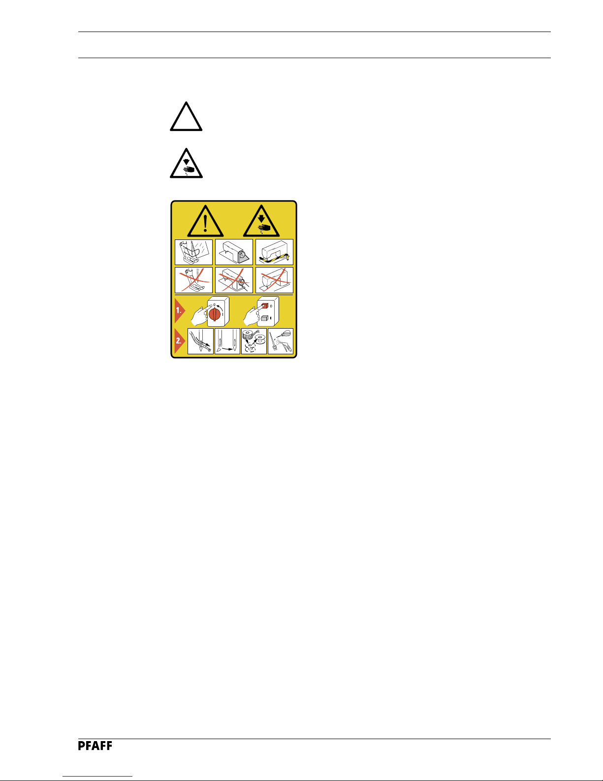
1.03 Safety symbols
Danger!
Points to be observed.
Danger of injury for operating and specialist personnel!
!
1.04 Important points for the user
● This Instruction Manual is a component part of the machine and must be available to the
operating personnel at all times.
● The Instruction Manual must be read before operating the machine for the first time.
● The operating and specialist personnel is to be instructed as to the safety equipment of the
machine and regarding safe work methods.
● It is the duty of the user to only operate the machine in perfect running order.
● It is the obligation of the user to ensure that none of the safety mechanisms are removed
or deactivated.
● It is the obligation of the user to ensure that only authorized persons operate and work on
the machine.
Further information can be obtained from your PFAFF agent.
I
Caution
Do not operate without finger guard and safety devices.
Before threading, changing bobbin and needle, cleaning
etc. switch off main switch.
Page 8

Safety
1 - 3
1.05 Operating and specialist personnel
1.05.01 Operating personnel
Operating personnel are persons responsible for the equipping, operating and cleaning of the
machine as well as taking care of faults arising in the sewing area.
The operating personnel is obliged to observe the following points and must:
● always observe the Notes on Safety in the Instruction Manual!
● never use any working methods which could limit the level of safety in using the machine!
● not wear loose-fitting clothing or jewellery such as chains or rings!
● also ensure that only authorized persons have access to the potentially dangerous area
around the machine!
● always immediately report to the person responsible any changes in the machine which
may limit its safety!
1.05.02 Specialist personnel
Specialist personnel are persons with a specialist education in the fields of electrics,
electronics and mechanics. They are responsible for the lubrication, maintenance, repair and
adjustment of the machine.
The specialist personnel is obliged to observe the following points and must:
● always observe the Notes on Safety in the Instruction Manual!
● switch off the On/Off switch before carrying out adjustments or repairs and ensure that it
cannot be switched on again unintentionally!
● never work on parts which are still connected to the power supply! Exceptions are
contained only in the regulations EN 50110.
● replace the protective coverings and close the electrical control box after all repairs or
maintenance work!
Page 9
Safety
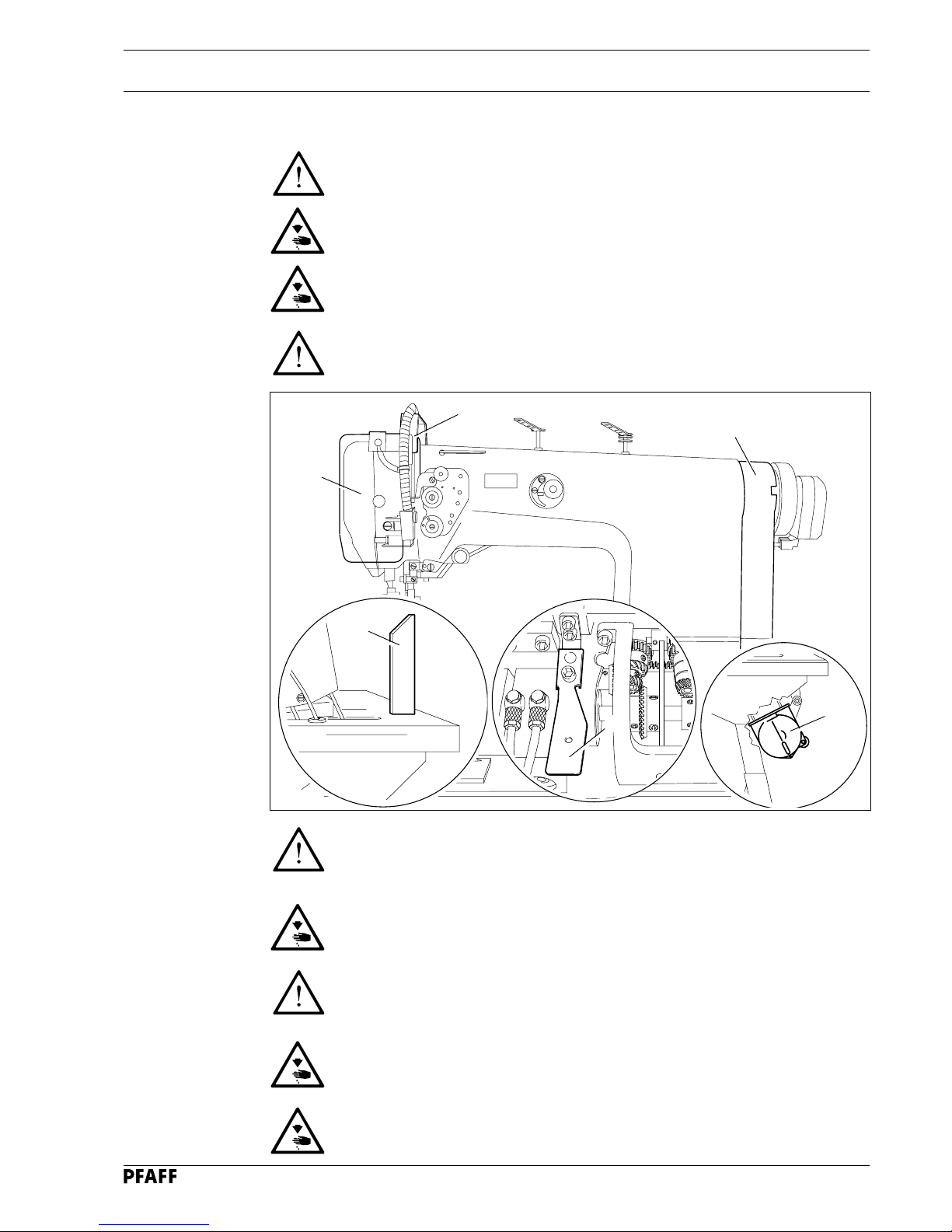
1 - 4
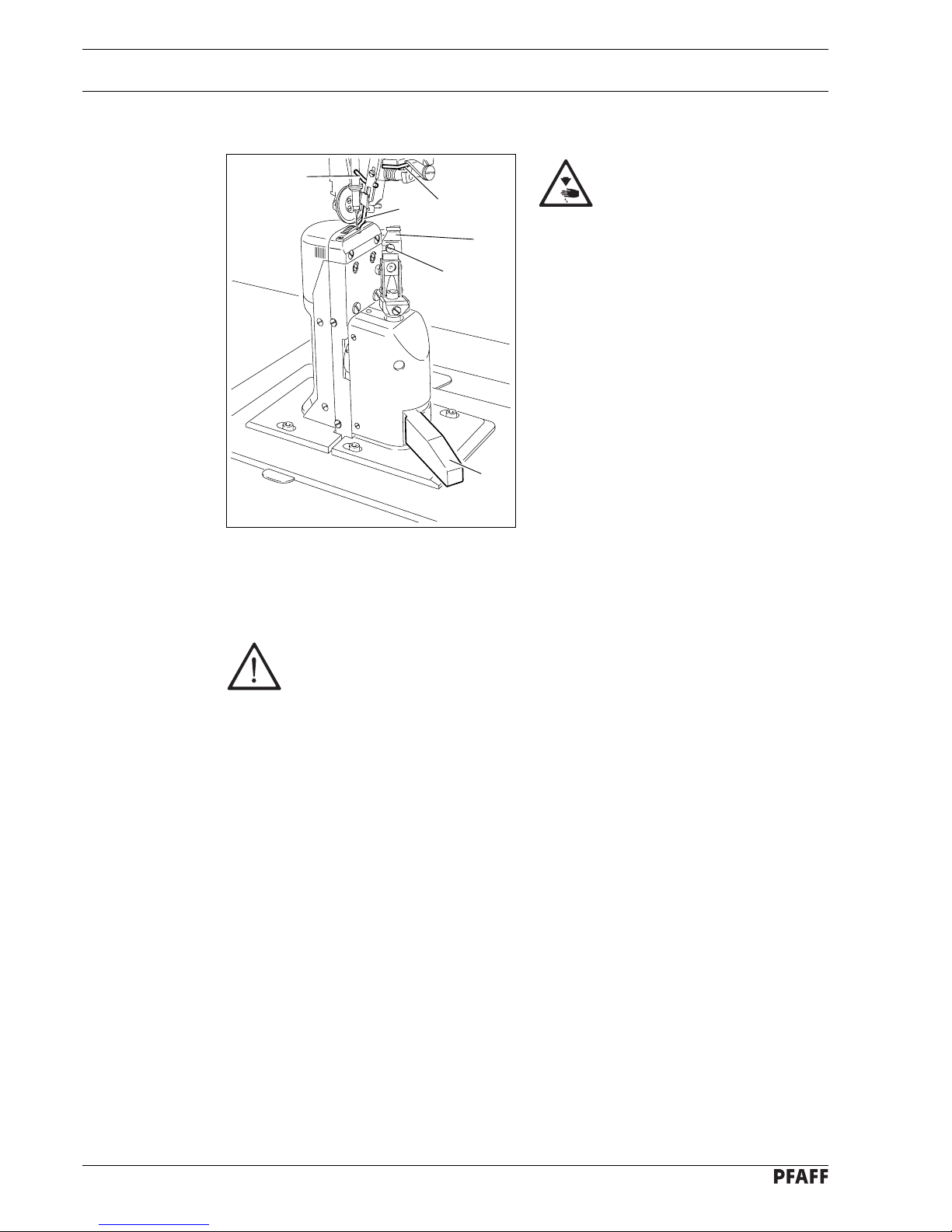
1.06 Danger
A working area of 1 meter is to be kept free both in front of and behind the
machine while it is in operation so that it is always easily accessible.
Never reach into the sewing area while sewing! Danger of injury by the needle!
Never leave objects on the table while adjusting the machine settings!
Objects can become trapped or be slung away! Danger of injury!
Switch the machine off before tilting it backwards!
Danger of injury if the machine is started accidentally!
Do not operate the machine without support 1! Danger due to top-heavy sewing
head! Machine can tip over backwards when tilted!
Do not operate the machine without its take-up-lever guard 2!
Danger of injury due to the motion of the take-up lever!
On machines with thread lubricator, only operate the machine with the eye
guard 3 lowered!
The eye guard 3 protects the eyes from oil particles from the thread lubrication.
Do not operate the machine without belt guard 4 and 5!
Danger of injury by rotating drive belt!
Do not operate the machine without tilt lock 6!
Danger of crushing between sewing head and table top!
2
4
Fig. 1 - 01
1
6
5
3
Page 10

Proper use
2 - 1
2 Proper use
The PFAFF 471 is a single needle, high-speed post bed sewing machine (post to the left
of the needle) with driven feed wheel and roller presser and synchronized
needle.
The PFAFF 474 is a two-needle, high-speed post bed sewing machine with driven feed
wheel and roller presser
The PFAFF 491 is a single needle, high-speed post bed sewing machine (post to the right
of the needle) with driven feed wheel and roller presser and synchronized
needle.
The machines are used for sewing lockstitch seams in the leather and upholstery industries.
Any use of these machines which is not approved by the manufacturer shall be
considered as improper use! The manufacturer shall not be liable for any damage arising out of improper use! Proper use shall also be considered to include
compliance with the operation, adjustment, service and repair measures specified by the manufacturer!
Page 11

Specifications
3 - 1
3 Specifications
3.01 PFAFF 471, 474 , 491
▲
Stitch type: .................................................................................................. 301 (lockstitch)
Balance wheel eff. diameter:.................................................................................... 65 mm
Fabric clearance (roller presser raised): ......................................................................7 mm
Clearance width: .................................................................................................... 245 mm
Clearance height:.................................................................................................... 115 mm
Post height: ............................................................................................................ 180 mm
Dimensions of sewing head:
Length: .......................................................................................................approx. 615 mm
Width:.........................................................................................................approx. 240 mm
Height (above table):...................................................................................approx. 450 mm
Size of bedplate: ............................................................................................518 x 177 mm
Max. speed:
Model A + B.........................................................................................2800 stichtes/min
◆
Model B/C ............................................................................................ 2500 stichtes/min
◆
Trimming margin (for -725/.. and -726/..): ....................................................... 0.8 - 2.5 mm
Trimming speed (for -725/.. and -726/..): ...................................................... 2800 cuts/min
Connection data:
Operating voltage: ........................................................................... 230 V ± 10%, 50/60 Hz
Max. power consumption:....................................................................................... 1.2 kVA
Fuse protection: ..............................................................................1 x 16 A, delayed action
Working noise level:
Emission at workplace
PFAFF 471 and 491 models A + B n = 2200 spm: ............................................... 80 dB(A)
PFAFF 471 and 491 models B/C n = 2000 spm:.................................................. 78 dB(A)
PFAFF 474 model B n = 2200 spm: ..................................................................... 81 dB(A)
PFAFF 474 model B/C n = 2000 spm: .................................................................. 79 dB(A)
( Noise measurement in accordance with DIN 45 635-48-A-1 )
Net weight of sewing head:............................................................................ approx. 53 kg
Gross weight of sewing head: ........................................................................ approx. 61 kg
▲
Subject to alteration
◆
Dependent on material, working cycle and stitch length
Page 12

Specifications
3 - 2
3.02 Needles and threads
Thread strength
▲
(Nm) max.
synthetic
Model
B 40/3 100 134 134 - 35
B/C 20/3 120 134 134 - 35
A 60/3 70 134 -
Needle size
in
1/100 mm
Needle system
for
PFAFF 471
and 491
▲
or similar strengths of other types of thread
3.03 Possible models and subclasses
Model A.............................................................................For sewing lightweight materials
Model B..................................................................... For sewing medium-weight materials
Model B/C ............................................... For sewing medium- to medium-heavy materials
Additional equipment:
Subclass -725/04 ............................................................................................ Edge trimmer
Subclass -726/05 ............................................................................................ Edge trimmer
Subclass -900/53 ......................................................................................... Thread trimmer
Subclass -906/10 ........................................................................................Thread tensioner
Subclass -910/15 ...................................................................... Automatic presser foot lifter
Subclass -911/35 .................................................................................................. Bartacker
Needle system
for the
PFAFF 474
Page 13

Disposal of Machine
4 - 1
4 Disposal of Machine
● Proper disposal of the machine is the responsibility of the customer.
● The materials used for the machine are steel, aluminium, brass and various plastic mat-
erials.
The electrical equipment comprises plastic materials and copper.
● The machine is to be disposed of according to the locally valid pollution control regulations; if necessary, a specialist ist to be commissioned.
Care must be taken that parts soiled with lubricants are disposed of separately
according to the locally valid pollution control regulations!
Page 14

Transportation, packing and storage
5 - 1
5 Transportation, packing and storage
5.01 Transportation to customer's premises
Within the Federal Republic of Germany, complete machines (with table and motor) are
delivered without packing.
Machines without table (only sewing heads) and machines intended for export are packed.
5.02 Transportation inside the customer's premises
The manufacturer cannot be made liable for transportation inside the customer's premises
nor to other operating locations. It must be ensured that the machines are only transported
in an upright position.
5.03 Disposal of packing materials
The packing materials of this machine comprise paper, cardboard and VCE fibre. Proper disposal of the packing material is the responsibility of the customer.
5.04 Storage
If the machine is not in use, it can be stored as it is for a period of up to six months, but It
should be protected against dust and moisture.
If the machine is stored for longer periods, the individual parts, especially the surfaces of
moving parts, must be protected against corrosion, e.g. by a film of oil.
Page 15

Explanation of symbols
6 - 1
6 Explanation of symbols
In this instruction manual, work to be carried out or important information is accentuated by
symbols. These symbols have the following meanings:
Note, information
Cleaning, care
Lubrication
Maintenance, repairs, adjustment, service work
(only to be carried out by technical staff)
Page 16
Controls
7 - 1
7 Controls
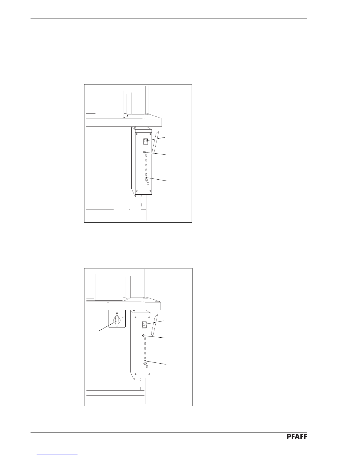
7.01 On/off switch on machines with mini-stop motor
without edge trimmer -725/.. or -726/..
● The machine is switched on or off by
pressing the on/off switch 1.
● The illuminated diode 2 controls the
machine operation
Switch 1 on:
Diode on = Machine ready for
operation
Diode flashes = Fault
Switch 1 off:
Diode flashes = Machine still
under electric
current for about
4 sec.
Diode out = Machine off
● The machine speed can be adjusted on
potentiometer 3.
7.02 On/off switch on machines with mini-stop motor
and edge trimmer -725/.. oder -726/..
● The machine is switched on or off by
turning the on/off switch 1.
● The illuminated diode 2 controls the
machine operation
Switch 3 on:
Diode on = Machine ready for
operation
Diode flashes = Fault
Switch 3 off:
Diode flashes = Machine still
under electric
current for about
4 sec.
Diode out = Machine off
● The machine speed can be adjusted on
potentiometer 4.
Fig. 7 - 02
1
Fig. 7 - 01
1
2
3
3
2
4
Page 17
Controls
7 - 2
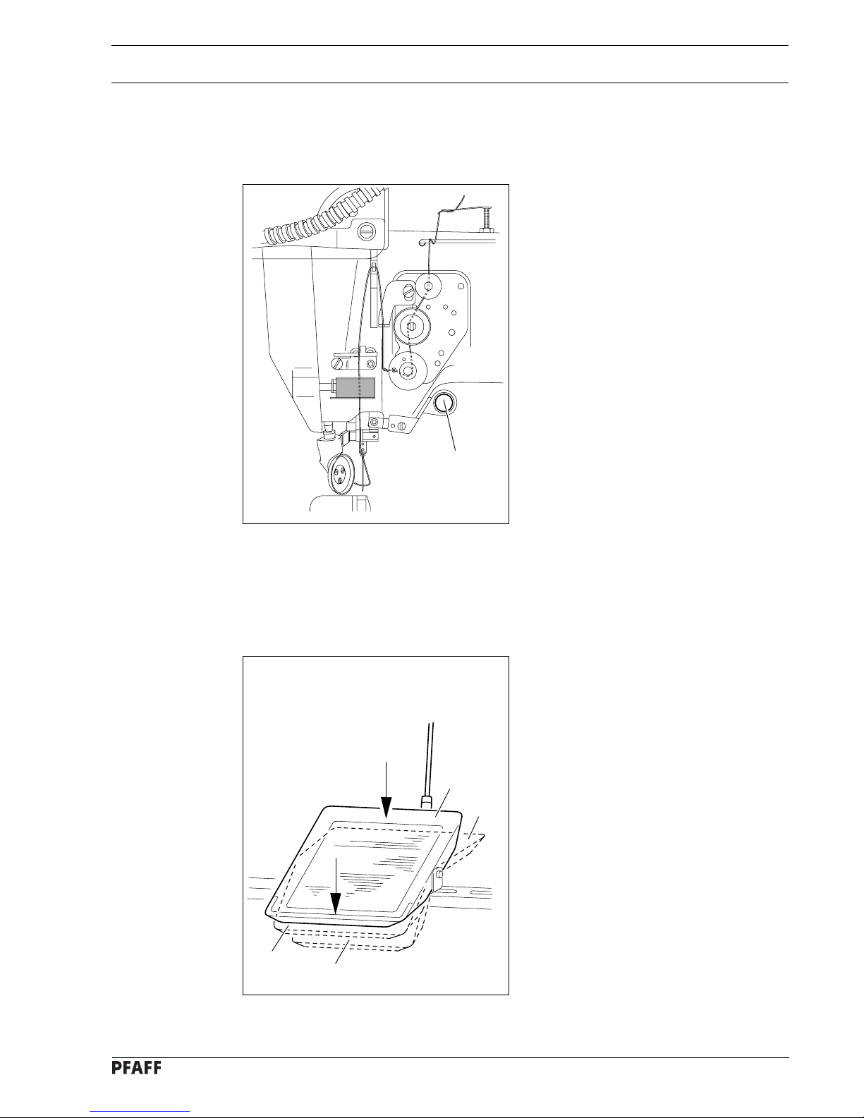
7.04 Pedal
0 = Neutral position
1 = Sewing
2 = Raise roller presser (on
machines with -910/..)
3 = Trim sewing threads (on
machines with -900/..)
Fig. 7 - 04
0
1
2
3
7.03 Button on machine head (only on machines with -911/..)
● If button 1 is operated during sewing, the
machine switches to reverse sewing.
Fig. 7 - 03
1
Page 18
Controls
7 - 3
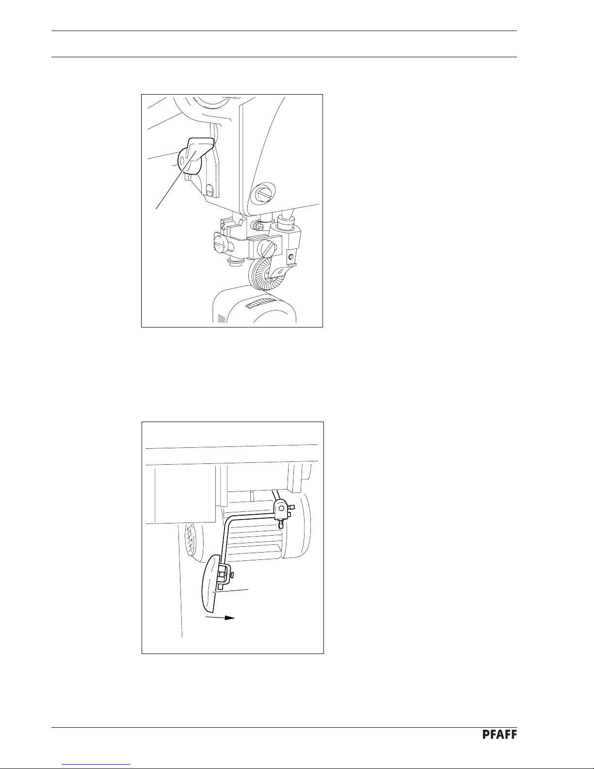
7.05 Lever for lifting roller presser
● The roller presser can be raised by turning
lever 1.
Fig. 7 - 05
1
7.06 Knee lever
● The roller presser can be raised by
pressing the knee lever 1 in the direction
of the arrow.
1
Fig. 7 - 06
Page 19
Controls
7 - 4
7.07 Key for setting stitch length
Fig. 7 - 07
● The stitch length is set by pressing key 1
and turning the balance wheel (see
Chapter 9.08 Setting the stitch length).
7.08 Swing out roller presser
● When the roller presser is raised, it can
be swung out by pulling it lightly
downwards.
Fig. 7 - 08
1
1
Page 20
Controls
7 - 5
7.09 Edge trimmer -725/04 for 471
Keep your hands away from the
moving knife! Danger of injury!
Switch on knife drive:
● Move lever 1 backwards. The knife
moves into operating position.
Switch off knife drive:
● Press lever 1. The knife swings
backwards.
Switch on edge guide:
● Swing edge guide 2 into position by hand
and press lever 3. The edge guide 2
moves into its operating position.
Switch off edge guide:
● Raise edge guide 2 and let it click into
position. The edge guide 2 is out of
operation.
● Raise lever 4. The edge guide swings
backwards.
Changing the knife:
The following work may only be carried out by technical staff or by persons who
have been properly instructed.
● Switch off the machine.
● Loosen screw 5 and remove knife 6.
● Insert new knife and slightly tighten screw 5.
● Adjust the knife according to Chaper 11.05.05 Cutting stroke and tighten screw 5.
Fig. 7 - 09
3
2 4
1
6
5
Page 21
Controls
7 - 6
7.10 Edge trimmer -725/04 for 474 and 491
Keep your hands away from the moving knife! Danger of injury!
Switch on knife drive:
● Move lever 1 backwards. The knife moves into operating position.
Switch off knife drive:
● Press lever 1. The knife swings backwards.
Switch on edge guide:
● Swing edge guide 2 into position by hand and press lever 3. The edge guide 2 moves into
its operating position.
Switch off edge guide:
● Raise edge guide 2 and let it click into position. The edge guide 2 is out of operation.
● Raise lever 4. The edge guide swings backwards.
Changing the knife:
The following work may only be carried out by technical staff or by persons who
have been properly instructed.
● Switch off the machine.
● Loosen screw 5 and remove knife 6.
● Insert new knife and push it close to needle plate insert 7.
● Slightly tighten screw 5.
● Adjust the knife according to Chaper 11.05.07 Knife position and tighten screw 5.
Fig. 7 - 10
1
2
4
3
6
5
7
Page 22
Controls
7 - 7
7.11 Edge trimmer -726/05 for 491
5
4
Fig. 7 - 11
Keep your hands away from the moving knife! Danger of injury!
Switch on knife drive:
● By turning lever 1 the knife is moved into its operating position.
Switch off knife drive:
● By pressing lever 2 or key 3 the knife is put out of operation.
Switch on edge guide:
● After lever 4 has been pressed, the edge guide moves into its starting position.
Switch off edge guide:
● By raising lever 5, the edge guide is put out of operation.
Changing the knife:
The following work may only be carried out by technical staff or by persons who
have been properly instructed.
● Switch off the machine.
● Loosen screw 6 and remove knife 7.
● Insert new knife and push it close to needle plate insert.
● Tighten screw 6.
● Adjust the knife according to Chapter 11.06.01 Position of the knife to the needle plate
and Chapter 11.06.02 Knife crosswise to sewing direction.
1
2
3
6
7
Page 23
Installation and commissioning
8 - 1
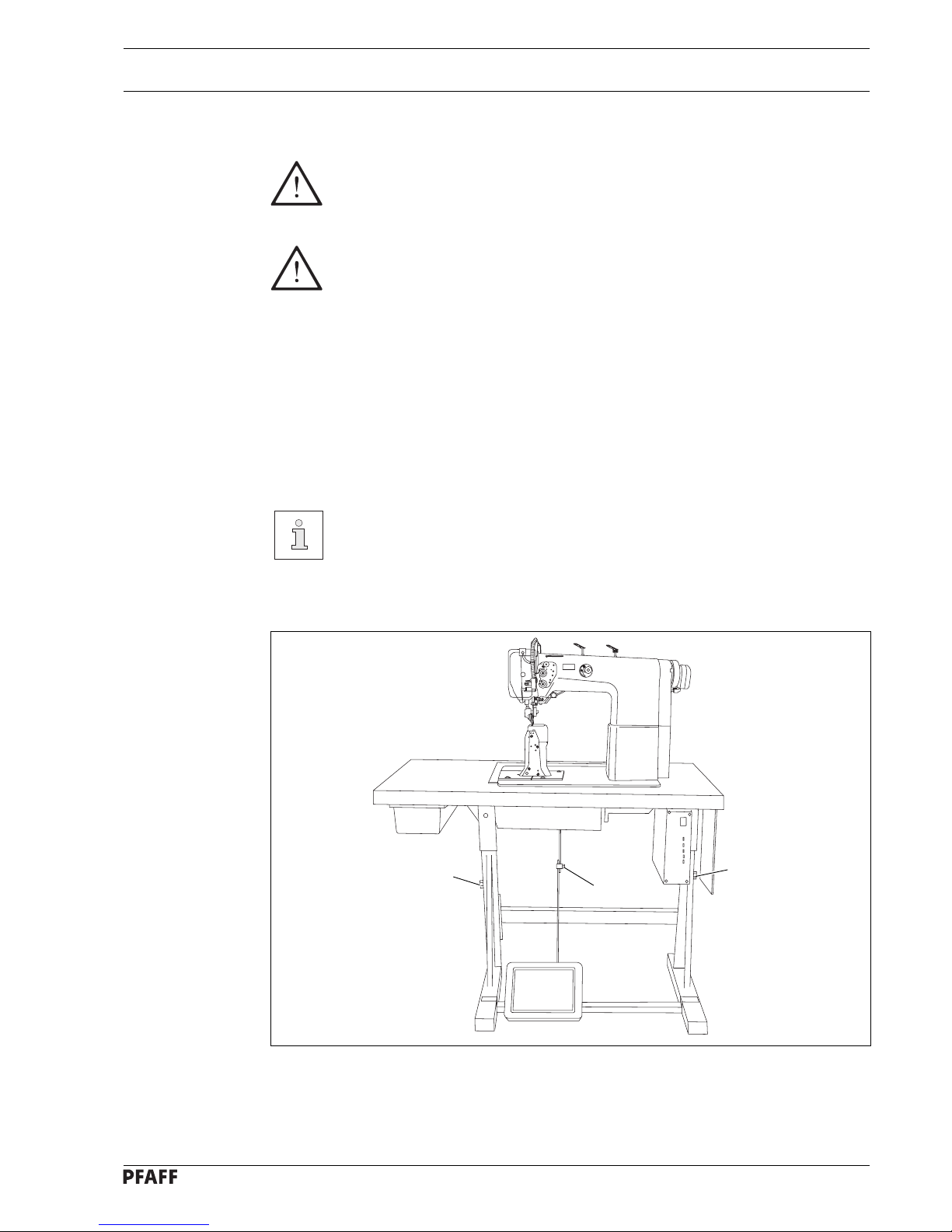
Fig. 8 - 01
1
2
1
8 Installation and commissioning
The machine must only be installed and commissioned by qualified personnel!
All relevant safety regulations must be strictly adhered to!
If the machine is delivered without a table, be sure to use a stand and table top
that can hold the weight of the machine with its motor.
It is very important to ensure that the stand of the machine is firm and steady,
also during sewing.
8.01 Installation
The site where the machine is installed must be provided with suitable connections for electric current.
It must be ensured that the standing surface of the machine site is firm and horizontal, and
that sufficient lighting is provided for.
For packing and transportation reasons the table top is in the lowered position.
The table height is adjusted as described below.
8.01.01 Adjusting the table height
● Loosen screws 1 and 2 and set the table height as required.
● Firmly tighten screw 1.
● Set the required pedal position and tighten screw 2.
Page 24
Installation and commissioning
8 - 2
Switch off the machine!
Danger of injury if the machine
is the machine is started
accidentally!
● Screw on the tilt lock 1, provided in the
accessories, using screw 2.
Do not operate the machine
without tilt lock 1. Danger of
crushing between sewing head
and table top!
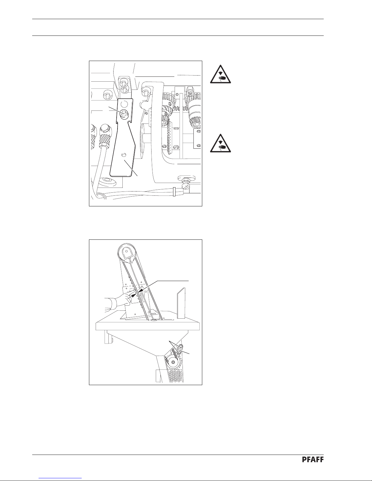
8.01.03 Tensioning the v-belt (does not apply to machines with mini-stop motor)
● Loosen the nuts 1.
● Set tension of v-belt using motor bracket 2
.
● Tighten nuts 1.
Fig. 8 - 03
1
2 cm
2
8.01.02 Fitting the tilt lock
Fig. 8 - 02
1
2
Page 25
Installation and commissioning
8 - 3
Fig. 8 - 04
2
7
1
3
6
9
9
4
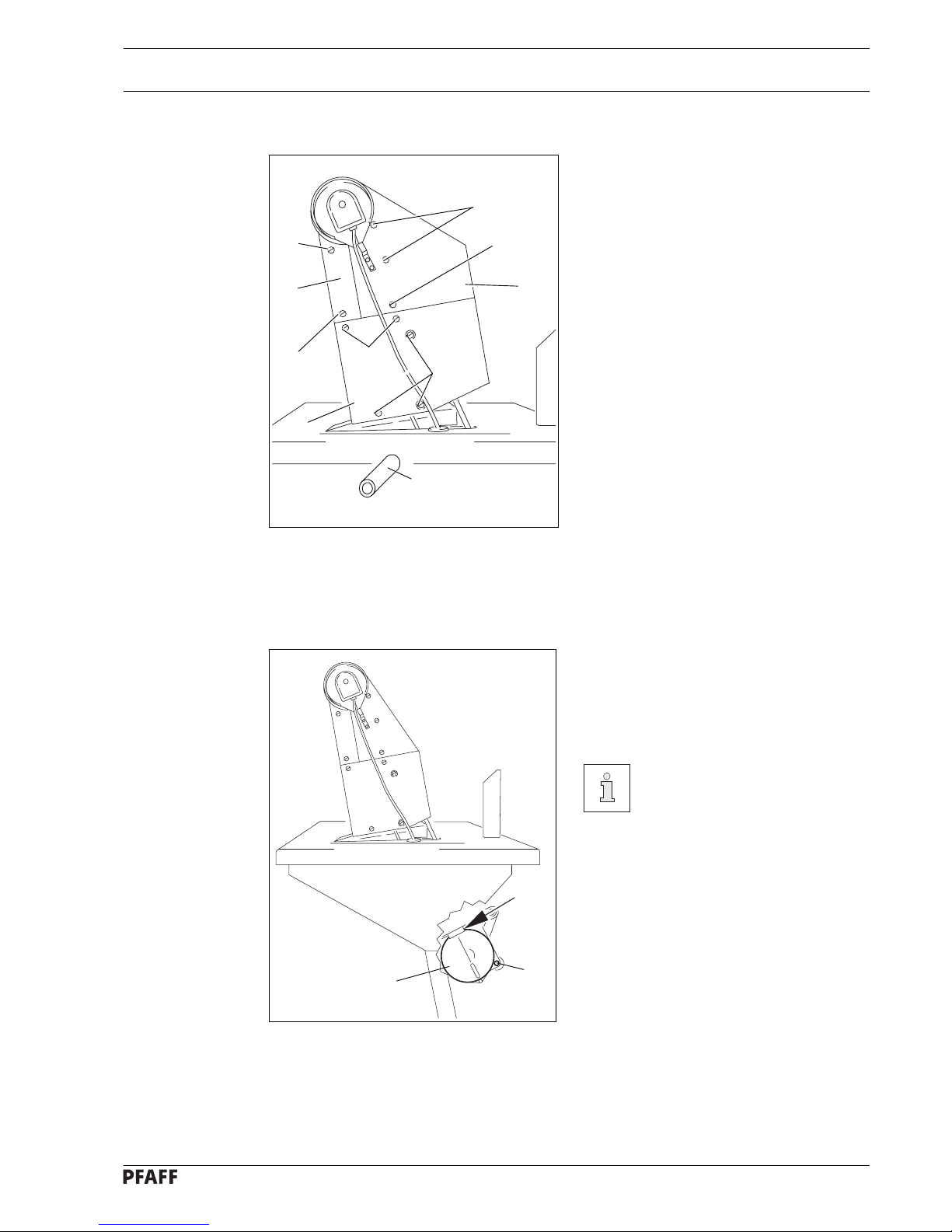
8.01.05 Fitting the bottom v-belt guard (does not apply to machines with mini-stop motor)
Fig. 8 - 05
● Adjust the v-belt guard 1 so that the
motor pulley and v-belt run freely.
● Tighten screws 2. Fig. 8-05 shows a
Quick motor.
If another motor is used, the
instruction manual of the motor
must be complied with.
1
2
2
5
8
8.01.04 Fitting the top v-belt guard
● Attach belt guard 1 with screws 2 and 3.
● Place spacing sleeve 4 between belt
guard 1 and the machine housing.
● Attach belt guard 5 with screws 6 and 7.
● Place spacing sleeve 4 between belt
guard 5 and the machine housing.
● Attach belt guard 8 with screws 9.
Page 26
Installation and commissioning
8 - 4
8.01.06 Fitting the synchronizer
● Attach position stop 1 using screws 2.
● Push synchronizer 3 onto the shaft so that
the position stop 1 is in the groove of the
synchronizer (see arrow).
● Slightly tighten screws 4.
● Insert the synchronizer plug in the
connection socket of the control box.
● Adjust the synchronizer 3 (see Chapter
11.04.01 Adjusting the Synchronizer).
Fig. 8 - 06
2
1
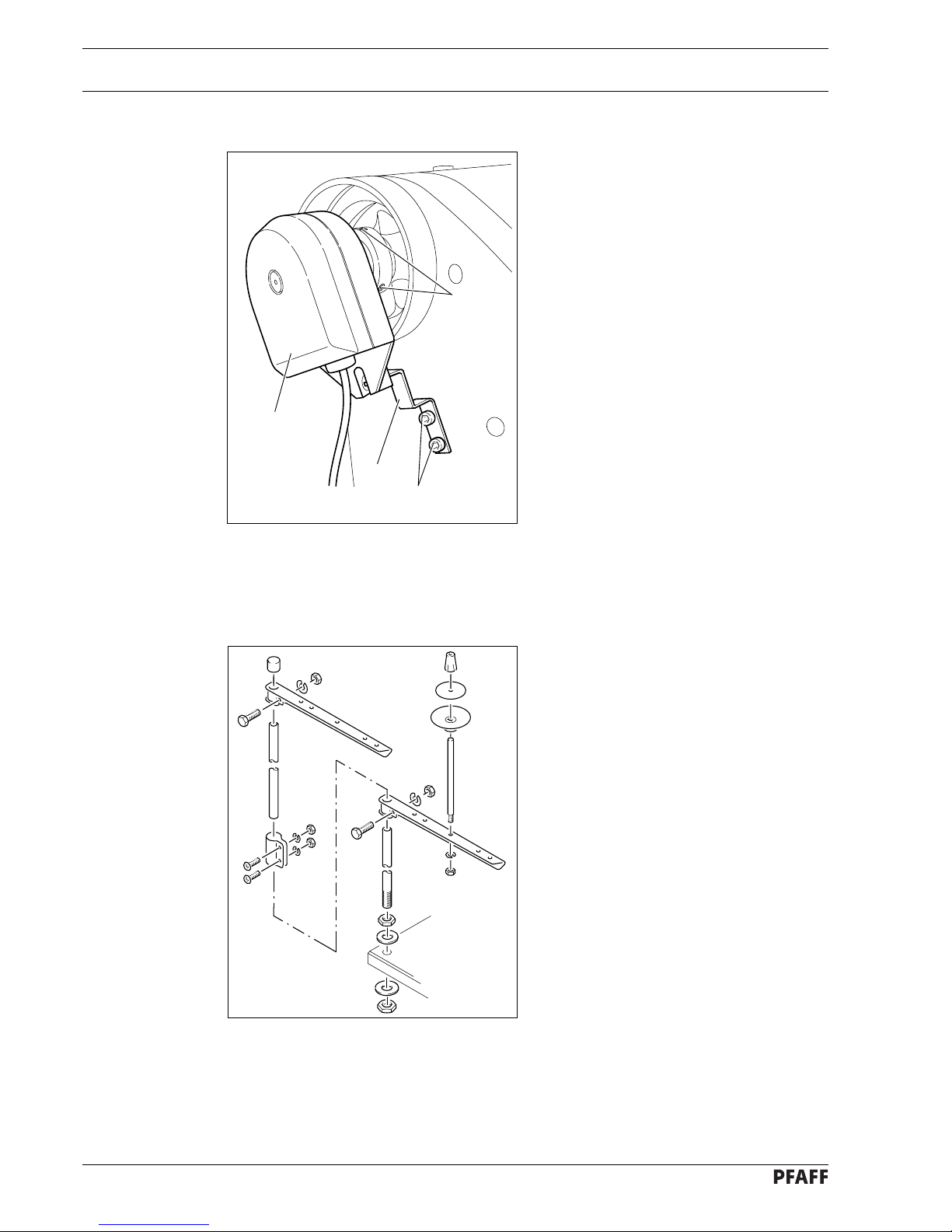
8.01.07 Fitting the reel stand
● Fit the reel stand as shown in Fig. 8-07.
● Afterwards insert the stand in the hole in
the table top and secure it with the nuts
provided.
Fig. 8 - 07
4
3
Page 27

Installation and commissioning
8 - 5
8.02 Commissioning
● Check the machine, particularly the electrical wiring, for any damage.
● Clean the machine thoroughly and then oil it or fill in oil (see Chapter 10 Care and
maintenance).
● Have a mechanic check whether the motor of the machine can be operated with the
available power supply, and that the motor is correctly connected in the junction box. If
there are any discrepancies the machine must not be operated under any
circumstances.
The machine may only be connected to an earthed socket!
● When the machine is running, the balance wheel must turn towards the operator. If it does
not, have the motor connection changed by a mechanic.
● Machines with pneumatic equipment must be connected to the compressed air supply.
The pressure gauge should indicate a pressure of 6 bar. If necessary, adjust to the correct
setting (see Chapter 10.05 Checking adjusting the air pressure).
8.03 Switching the machine on/off
● Switch the machine on or off (see Chapter 7.01 On/off switch).
Page 28
Setting up
9 - 1
9 Setting up
All instructions and regulations in this instruction manual must be observed.
Special attention must be paid to all safety regulations!
All setting-up work must only be carried out by personnel with the appropriate
training. For all setting-up work the machine must be disconnected from its
power supply by turning off the on/off switch, or removing the plug from the
electric power socket.
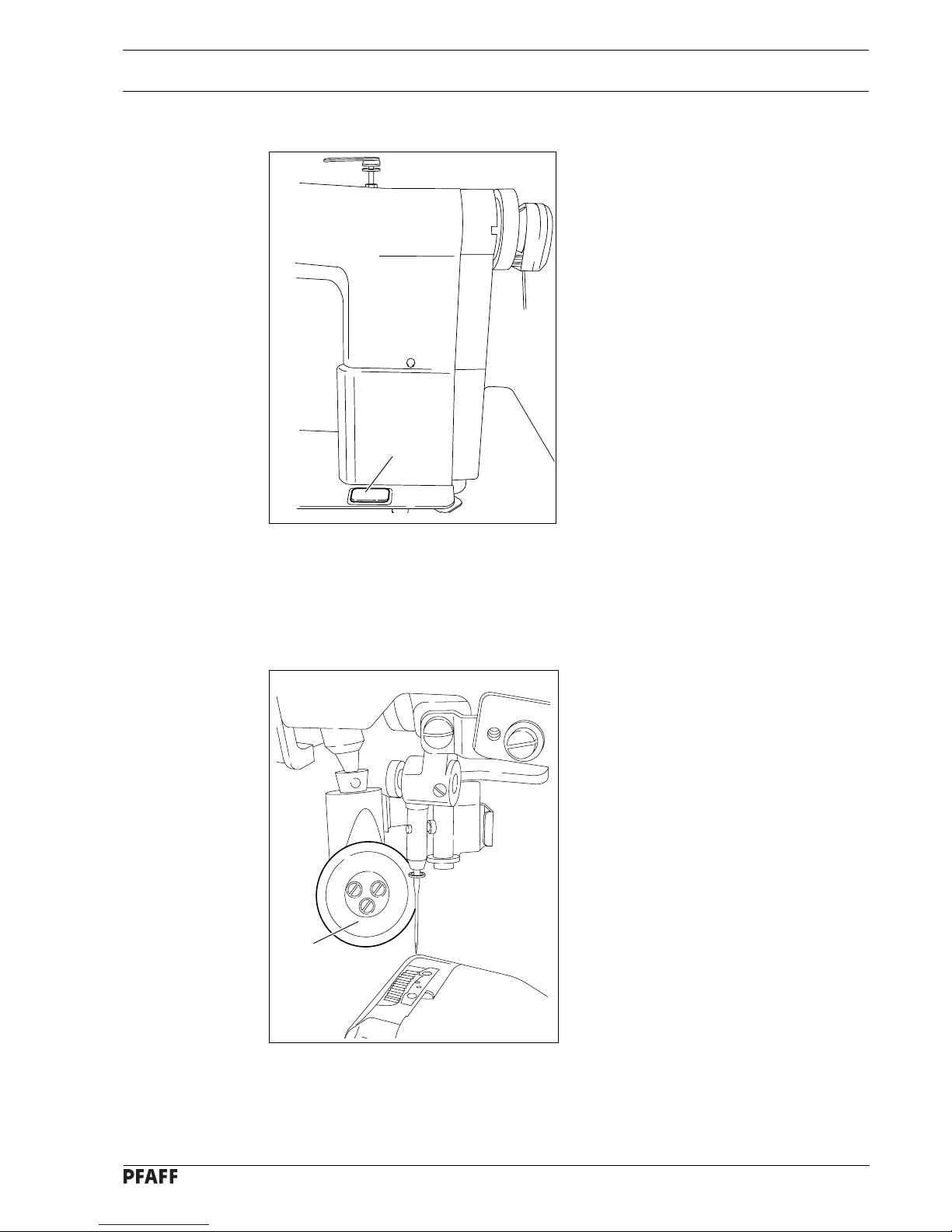
9.01 Inserting the needle on model 471 and 491
Switch the machine off!
Danger of injury if the machine
is started accidentally!
Only use needles of system 134.
● Raise the roller presser 1 and swing it
out.
● Loosen screw 2 and insert the needle as
far as possible. The long groove must
face to the right on model 471 and to the
left on model 491.
● Tighten screw 2 and swing roller presser 1
back into position.
Fig. 9-01 shows model 491.
1
The choice of needle depends on the model of the machine and the thread and
material used (see Chapter 3.02 Needles and threads).
Fig. 9 - 01
2
Page 29
Setting up
9 - 2
9.02 Inserting the needle on model 474
Switch the machine off!
Danger of injury if the machine
is started accidentally!
Only use needles of system 134-35.
● Raise the roller presser 1 and swing it
out.
● Loosen screws 2 and insert the needles
so that the long groove of the left needle
is facing right, and that of the right needle
is facing left.
● Tighten screws 2 and swing roller
presser 1 back into position.
Fig. 9 - 02
The choice of needle depends on the model of the machine and the thread and
material used (see Chapter 3.02 Needles and threads).
1
2
2
Page 30
Setting up
9 - 3
2
1
4
_
+
Fig. 9 - 03
5
6
3
9.03 Winding the bobbin thread; adjusting the primary thread tension
● Place an empty bobbin 1 onto bobbin winder spindle 2.
● Thread the bobbin as shown in Fig. 9 - 03 and wind it clockwise around bobbin 1 a few
times.
● Switch on the bobbin winder while at the same time pressing bobbin winder spindle 2 and
lever 3.
The bobbin is filled up during sewing.
● The thread tension on bobbin 1 can be adjusted using knurled screw 4.
● The bobbin winder stops automatically when bobbin 1 is full.
If the thread is wound unevenly:
● Loosen nut 5.
● Turn thread guide 6 accordingly.
● Tighten nut 5.
Page 31

Setting up
9 - 4
Fig. 9 - 04
2
3
-
+
1
5 cm
Fig. 9 - 05
1
2
Turn the machine off!
Removing the bobbin case:
● Open the post cap.
● Raise latch 1 and remove bobbin case 2.
Inserting the bobbin case:
● Insert bobbin case 2.
● Close the latch and close the post cap.
474 is shown in Fig. 9 - 04.
9.04 Removing/Inserting the bobbin case
9.05 Threading the bobbin case/Adjusting the bobbin thread tension
● Insert the bobbin into the bobbin case 1.
● Pass the thread through the slot under
spring 2.
● Pass the thread through the notch.
● Adjust the thread tension by turning
screw 3.
When the thread is pulled, the
bobbin must rotate in the
direction of the arrow.
Page 32

Setting up
9 - 5
9.06 Threading the needle thread and regulating its tension on model 471/491
1
Fig. 9 - 06
Switch the machine off!
Danger of injury if the machine is started accidentally!
● Tilt up the eye guard 1.
● Thread the needle thread as shown in Fig. 9-06.
● On model 471 the needle is threaded from the right to the left, and on model 491 from the
left to the right.
● Adjust the needle thread tension by turning milled screw 2.
2
Page 33

Setting up
9 - 6
9.07 Threading the needle thread and regulating its tension on model 474
Fig. 9 - 07
Switch the machine off!
Danger of injury if the machine is started accidentally!
● Tilt up the eye guard 1.
● Thread both needle threads as shown in Fig. 9-07.
● The left needle is threaded from the right to the left, and the right needle from the left to the
right.
● Adjust the needle thread tensions by turning milled screws 2.
1
2
Page 34

Setting up
9 - 7
9.08 Setting the stitch length
Fig. 9 - 08
3
2
1
● Press key 1 and at the same time turn the balance wheel until the stitch setter clicks into
position.
● Hold down key 1 and turn the balance wheel to and fro until the stitch length required is
shown on the scale 2 opposite the bottom edge 3 of the belt guard recess.
Page 35

Care and maintenance
10 - 1
10 Care and maintenance
Clean........................................................daily, more frequently if in continuous operation
Oil level (thread lubrication) ............................................................. daily, before operation
Oil the hook ..................................................................................... daily, before operation
Lubricate the bevel gears................................................................................. once a year
Check/adjust air pressure ................................................................ daily, before operation
Clean air filter of air-filter/lubricator .............................................................. when required
Fig. 10 - 01
5 mm
2
1
These maintenance intervals are calculated for the average running time of a single shift operation. If the machine is operated more than this, shorter intervals
are recommended.
10.01 Cleaning
Clean the hook and hook compartment daily, more often if in continuous operation.
Switch the machine off!
Danger of injury if the machine
is started accidentally!
● Bring the needle bar to its highest
position.
● Open the post cap and remove the bobbin
case cap and the bobbin.
● Unscrew hook gib 1.
● Turn the handwheel until the point of bob-
bin case 2 penetrates into the groove of
the hook race approx. 5 mm.
● Remove bobbin case 2.
● Clean the hook race with paraffin.
● When inserting the bobbin case 2, ensure
that the horn of the bobbin
case 2 engages in the groove of the
needle plate.
● Screw hook gib 1 back on and close the
post cap.
Page 36

Care and maintenance
10 - 2
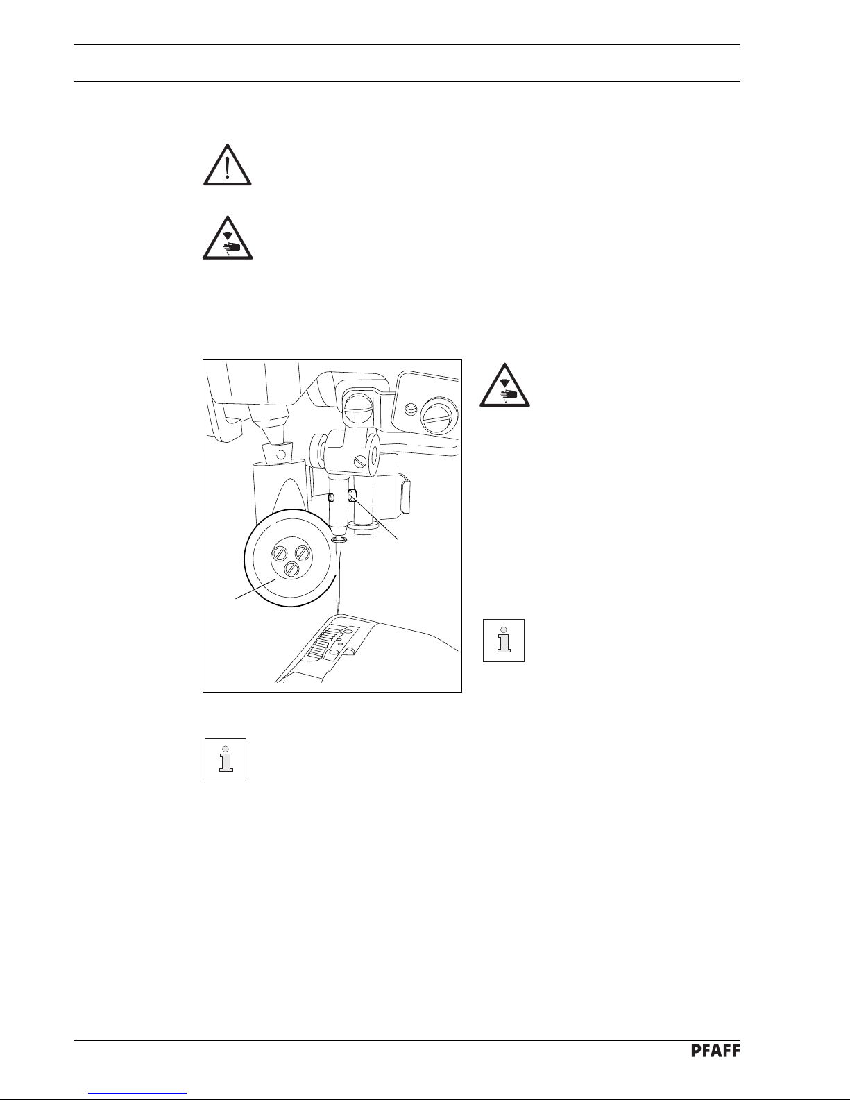
10.02 Oiling the hook
Switch the machine off!
Danger of injury if the machine
is started accidentally!
● Pour 1-2 drops of oil into hole 1 of the
hook gib daily.
● Before commissioning the machine, and
after long periods out of operation, pour a
few drops of oil into the hook race (see
arrow).
Fig. 10 - 02
1
10.03 Filling the oil reservoir of the thread lubrication unit
Control the oil level before each
use.
There must always be oil in the
reservoir.
● If necessary, fill oil up to mark 2 through
hole 1.
We recommend
PFAFF thread lubricating oil,
Order No. 280-1-120 217.
Fig. 10 - 03
1
2
Page 37

Care and maintenance
10 - 3
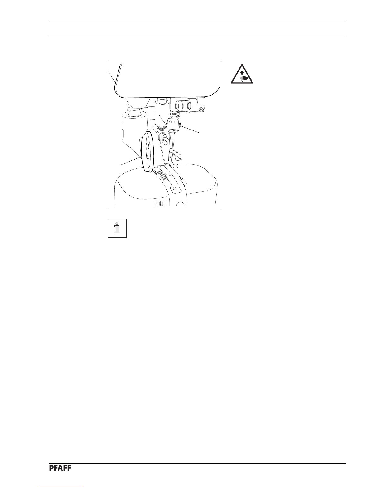
Switch the machine off!
Danger of injury if the machine is started accidentally!
● Once a year new grease must be applied to the bevel gears, which drive the hook and the
toothed rack.
● Tilt the sewing head back onto the support.
Fig. 10-04 shows the bevel gears of the 474.
● Apply grease to all the tooth flanks and the rack (see arrows).
● To set the sewing head upright, press tilt lock 1 backwards and set the sewing head
upright using both hands.
Use both hands to set the sewing head upright!
Danger of crushing between the sewing head and the table top!
We recommend PFAFF sodium grease with a dripping point of approx. 150C,
Order No. 280-1-120 243.
Fig. 10 - 04
10.04 Lubricating the bevel gears
1
Page 38

Care and maintenance
10 - 4
10
12
0
6
4
2
8
16
14
100
50
150
0
200
230
Fig. 10 - 05
Fig. 10 - 06
2
1
10
12
0
6
4
2
8
16
14
100
50
150
0
200
230
1
2
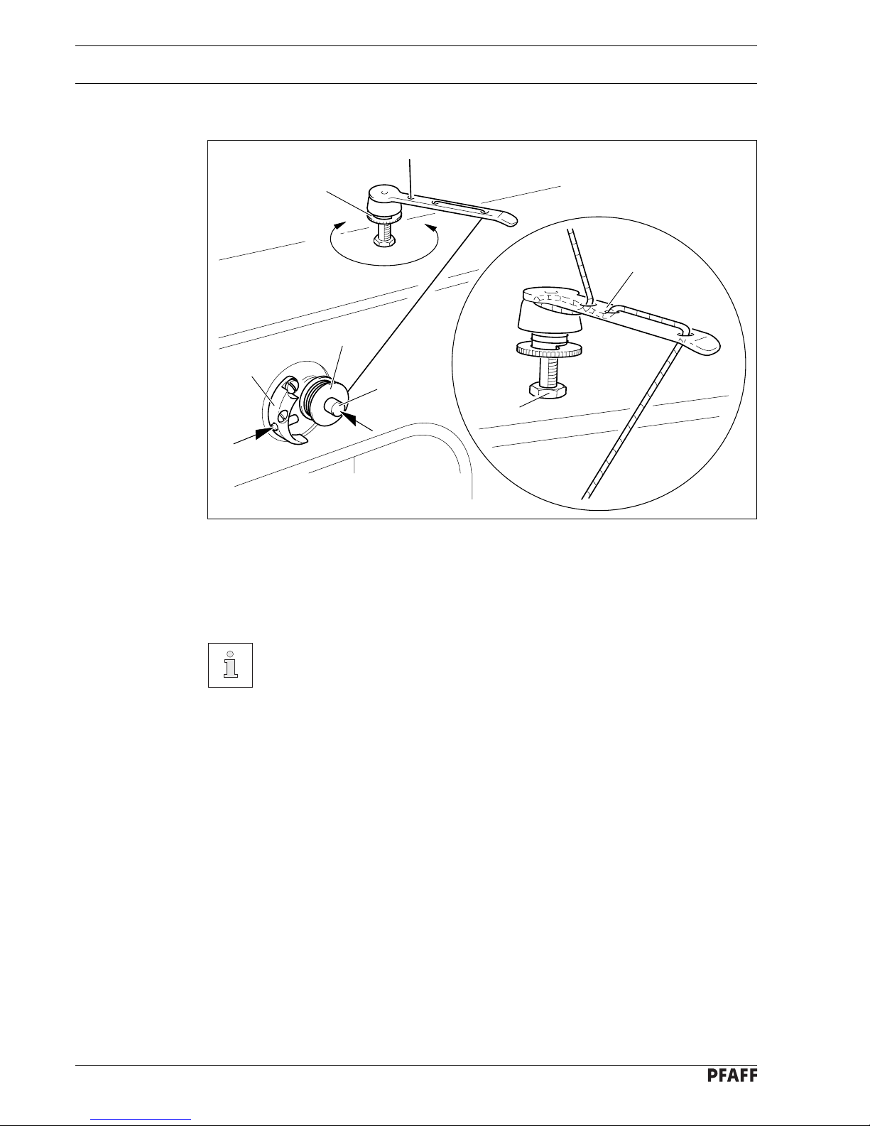
10.04 Cleaning the air filter of the air-filter/lubricator
Switch the machine off!
Disconnect the air hose at the
air-filter/lubricator.
To drain water bowl 1:
● Water bowl 1 drains itself automatically
when the compressed-air hose is disconnected from the air-filter/lubricator.
Cleaning filter 2:
● Unscrew water bowl 1.
● Take out filter 2.
● Clean filter 2 with compressed air or iso-
propyl alcohol (part No. 95-665 735-91).
● Screw in filter 2 and screw on water
bowl 1.
10.03 Checking/adjusting the air pressure
● Before operating the machine, always
check the air pressure on gauge1.
● Gauge 1 must show a pressure of 6 bar.
● If necessary adjust to this reading.
● To do so, pull knob 2 upwards and turn it
so that the gauge shows a pressure of 6
bar.
Page 39

Adjustment
11 - 1
11 Adjustment
11.01 Notes on adjustment
All adjustments in these adjustment instructions are based on a completely installed machine
and must only be carried out by appropriately trained specialists. Covers on the machine,
which have to be removed and replaced for checks and adjustment work, are not mentioned
here.
The screws and nuts in brackets ( ) are attachments of machine parts which are to be
loosened before making the adjustment and tightened again after the adjustment has been
carried out.
The machine must be switched off for all adjustment work!
Danger of injury if the machine is started accidentally!
11.02 Tools, gauges and other accessories
● 1 set of screwdrivers with blade widths from 2 to 10 mm
● 1 set of open-ended wrenches with opening sizes from 7 to 13 mm
● 1 set of allen keys from 1.5 to 6 mm
● 1 clamp (Order No. 08-880 137-00)
● 1 metal rule (Order No. 08-880 218-00)
● 1 gauge (Order No. 08-880 136-01)
● Sewing thread and test material
11.03 Abbreviations
TDC = top dead center
BDC = bottom dead center
Page 40

Adjustment
11 - 2
11.04 Adjusting the basic machine
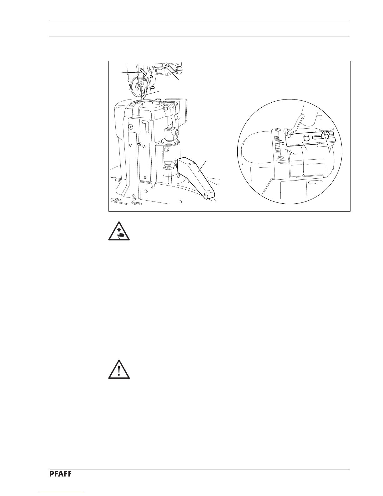
11.04.01 Adjusting the synchronizer
Requirements
1. When sewing is interrupted, the machine must be in a position 5 mm before BDC of
the needle bar.
2. After thread trimming the machine must be in the position TDC of the take-up lever.
Fig. 11 - 01
● Carry out adjustments according to the motor instruction manual.
● See also Chapter 11.10 Parameter settings.
Page 41

Adjustment
11 - 3
11.04.02 Needle position in sewing direction on the PFAFF 471 and 491
Requirement
With the stitch length set at its minimum, the needle should be positioned in the centre of
the needle hole, as seen in the direction of sewing.
Fig. 11 - 02
● Set the minimum stitch length.
● Adjust needle bar (screw 1) according to the requirement.
1
Page 42

Adjustment
11 - 4
11.04.03 Needle position in sewing direction on the PFAFF 474
Requirement
The needle should be positioned in the centre of the needle hole as seen in the direction of
sewing.
Fig. 11 - 03
1
● Adjust needle bar (screws 1 and 2) according to the requirement.
Screw 2 is accessible through a hole on the rear side of the case.
2
Page 43

Adjustment
11 - 5
11.04.04 Preliminary adjustment of the needle height
Requirement
When the needle bar is at TDC, there must be a clearance of approx. 22 mm between the
needle point and the needle plate.
Fig. 11 - 04
1
2
22 mm
● Adjust needle bar 1 (screw 2), without turning it, according to the requirement.
Page 44

Adjustment
11 - 6
4
11.04.05 Needle rise, hook clearance, needle height and needle guard on the PFAFF 471
Requirement
With the needle bar positioned 1.8 mm after BDC and the stitch length set at "0.8"
1. the hook point must be at needle centre with a hook-to-needle clearance of
0.05 to 0.1 mm;
2. the top of the needle eye must be 0.8 to 1.0 mm below the hook point;
3. the needle guard 6 must touch the needle lightly.
0.8 - 1 mm
6
5
● Set stitch length at "0.8".
● Loosen both screws 1, 2, 3, 4 and 5.
● Bring needle bar to 1.8 mm past BDC:
● Set hook point at needle centre, making sure that the needle is not deflected by needle
guard 6.
● Adjust needle height according to Requirement 2.
● Adjust hook post according to Requirement 1 and tighten screws 4 and 5.
Fig. 11 - 05
2
3
5
7
8
3
1
Page 45

Adjustment
11 - 7
● Making sure that there is some play in the bevel gear, tighten screws 1.
● With retaining collar 7 touching bevel gear 8 tighten screws 2 and 3.
● Adjust needle guard 6 according to Requirement 3.
10
When the hook is replaced, care
must be taken to see that markings 9
and 10 are on the same side.
9
Page 46

Adjustment
11 - 8
11.04.06 Needle rise, hook clearance, needle height and needle guard on the PFAFF 474
Requirement
With the needle bar positioned 1.8 mm after BDC on both hooks
1. the hook point must be at needle centre with a hook-to-needle clearance of
0.05 to 0.1 mm;
2. the top of the needle eye must be 0.8 to 1.0 mm below the hook points;
3. the needle guard 9 must touch the needle lightly.
● Loosen screws 1, 2, 3, 4, 5, 6 and 7.
● Loosen screws 8 slightly.
● Bring needle bar to 1.8 mm past BDC:
● Set both hook points at needle centre, making sure that the needles are not deflected by
needle guard 9.
● Adjust needle height according to Requirement 2.
● Adjust both hook posts according to Requirement 1 and tighten screws 8.
Fig. 11 - 06
7
7
8
8
9
5
2
11
10
12
13
0.8 - 1 mm
3
4
6
1
Page 47

Adjustment
11 - 9
● Tighten screws 1 and 6.
● Making sure that there is some play in the bevel gear, tighten screws 3 and 5.
● With retaining collar 10 touching bevel gear 11 tighten screws 2.
● With retaining collar 12 touching bevel gear 13 tighten screws 4.
● Tighten screws 7 on both sides of the post.
● Adjust needle guard 9 on both hooks according to Requirement 3.
When the hook is replaced, care must
be taken to see that markings 14 and
15 are on the same side.
15
14
Page 48

Adjustment
11 - 10
11.04.07 Needle rise, hook clearance, needle height and needle guard on the PFAFF 491
Requirement
With the needle bar positioned 1.8 mm after BDC and the stitch length set at "0.8"
1. the hook point must be at needle centre with a hook-to-needle clearance of
0.05 to 0.1 mm;
2. the top of the needle eye must be 0.8 to 1.0 mm below the hook point;
3. the needle guard 6 must touch the needle lightly.
4
5
5
4
● Set stitch length at "0.8".
● Loosen screws 1, 2, 3, 4 and 5.
● Bring needle bar to 1.8 mm past BDC:
● Set hook point at needle centre, making sure that the needle is not deflected by needle
guard 6.
● Adjust needle height according to Requirement 2.
● Adjust hook post according to Requirement 1 and tighten screws 4.
● Making sure that there is some play in the bevel gear, tighten screws 2.
● With retaining collar 7 touching bevel gear 8 tighten screws 1.
● Screws 5 remain loosened for further adjustments.
6
0,8 - 1 mm
Fig. 11 - 07
1
2
3
7
8
Page 49

Adjustment
11 - 11
● Adjust needle guard 6 according to Requirement 3.
When the hook is replaced, care must
be taken to see that markings 9 and 10
are on the same side.
10
9
Page 50

Adjustment
11 - 12
11.04.08 Needle position crosswise to sewing direction on the PFAFF 471
Requirement
When the stitch length is set at its maximum, the needle must be positioned in the centre
of the needle hole when entering and coming out of the needle plate.
Fig. 11 - 08
2
2
1
● Turn screws 1 (screws 2, on both sides of the post) according to the requirement.
Page 51

Adjustment
11 - 13
11.04.09 Needle position crosswise to sewing direction on the PFAFF 474
Requirement
As seen crosswise to the sewing direction, the needles must penetrate in the centre of
their needle holes.
● Adjust feed wheel post 1 (screws 2, on both sides of the post) according to the
requirement.
Fig. 11 - 09
2
2
1
Page 52

Adjustment
11 - 14
11.04.10 Needle position crosswise to sewing direction on the PFAFF 491
Requirement
As seen crosswise to the sewing direction, the needle must penetrate in the centre of the
needle hole.
Fig. 11 - 10
● Adjust feed wheel post 1 (screws 2, 3 and 4) according to the requirement.
1
2
2
4
4
4
4
3
Page 53

Adjustment
11 - 15
11.04.11 Height of the bobbin-case opener
Requirement
The top edges of the bobbin-case opener 1 and the bobbin case base 3 must be level.
Fig. 11 - 11
● Adjust the bobbin-case opener 1 (screws 2) according to the requirement.
Repeat the adjustment on the right-hand post for the 474.
1
3
2
1
Page 54

Adjustment
11 - 16
11.04.12 Bobbin-case opener stroke
Requirement
When the bobbin-case opener has pushed the bobbin case down as far as possible, the tip
of the bobbin case must be 0.3 - 0.5 mm from the rear edge of the needle plate recess.
● Turn the balance wheel until the bobbin-case opener has pushed the bobbin case down as
far as possible.
● Adjust the bobbin-case base (screw 1) according to the requirement.
Repeat the adjustment on the right-hand post for the 474.
This setting may differ according to the thread thickness.
Fig. 11 - 12
1
0.3 - 0.5 mm
Page 55

Adjustment
11 - 17
11.04.13 Height of the feed wheel on the PFAFF 471
Requirement
1. When pressure is applied to the feed wheel 4, it should protrude from the needle plate
by tooth height (approx. 0.8 mm)
2. When no pressure is applied to the feed wheel 4 , it should have a vertical play of
approx. 0.3 mm.
Fig. 11 - 13
● Swing out the roller presser.
● Loosen screws 1 and 2.
● Adjust drive wheel 3 according to requirement 1, taking care to see that the teeth of drive
wheel 3 and feed wheel 4 lock into each other properly.
● Tighten screws 1.
● Adjust guide 5 according to requirement 2 and tighten screws 2.
2
3
0.8 mm
0.3 mm
5
4
1
1
Page 56

Adjustment
11 - 18
11.04.14 Height of the feed wheel on the PFAFF 474
Requirement
1. When pressure is applied to the feed wheel 4, it should protrude from the needle plate
by tooth height (approx. 0.8 mm)
2. When no pressure is applied to the feed wheel 4 , it should have a vertical play of
approx. 0.3 mm.
Fig. 11 - 14
● Swing out the roller presser.
● Loosen screws 1 and 2 (two screws).
● Adjust drive wheel 3 according to requirement 1, taking care to see that the teeth of drive
wheel 3 and feed wheel 4 lock into each other properly.
● Tighten screws 1.
● Adjust guide 5 according to requirement 2 and tighten screws 2.
3
0.8 mm
0.3 mm
5
4
1
1
2
Page 57

Adjustment
11 - 19
11.04.15 Height of the feed wheel on the PFAFF 491
Requirement
The feed wheel should protrude from the needle plate by tooth height (approx. 0.8 mm)
1
2
3
● Swing out the roller presser.
● Loosen screws 1.
● Adjust eccentric 3 (fastening screw accessible through hole 2) according to the
requirement.
● Tighten screws 1.
Fig. 11 - 15
0.8 mm
Page 58

Adjustment
11 - 20
11.04.16 Stitch length control eccentric
Requirement
When the needle (with maximum stitch length set), coming from TDC, is 3 mm above the
needle plate, the crank 3 must have reached its front point of reversal.
2
● Set the maximum stitch length.
● Turn stitch length control device 1 (screws 2) according to the requirement.
Fig. 11 - 16
1
3
Page 59

Adjustment
11 - 21
11.04.17 Stitch length scale disk
Requirement
When the stitch length control device is locked in position, and the maximum stitch length
is set, the marking line of the highest number on the scale disk 1 must be opposite the
lower edge 3 of the belt guard recess.
3
● Set the maximum stitch length.
● Turn the scale disk 1 (screws 2) according to the requirement.
Fig. 11 - 17
2
1
Page 60

Adjustment
11 - 22
11.04.18 Shaft crank to feed wheel drive
Requirement
When the maximum stitch length is set, the linkage rod 3, or linkage rods 3 and 4 on the
models 471 and 491, must be able to move freely when the balance wheel is turned.
● Set the maximum stitch length.
● Twist or shift the shaft crank 1 (screw 2) according to the requirement.
Fig. 11 - 18
PFAFF 471
PFAFF 491
PFAFF 474
2
1
2
1
3
3
4
Page 61

Adjustment
11 - 23
11.04.19 Shaft crank to roller presser drive
Requirement
When the maximum stitch length is set, the linkage rods 3 and 4 must be able to move
freely at their left and right point of reversal when the balance wheel is turned.
● Set the maximum stitch length.
● Twist clamp crank 1 (screw 2) according to the requirement.
Fig. 11 - 19
2
1
3
4
Page 62

Adjustment
11 - 24
11.04.20 Clearance between roller presser and feed wheel
Requirement
When the presser bar lifter is raised, the clearance between the roller presser and the feed
wheel must be 7 mm.
● Raise the presser bar lifter.
● Adjust the presser bar 1 (screws 2) according to the requirement. Make sure that the
roller presser is parallel to the feed wheel.
Fig. 11 - 20
7 mm
1
2
Page 63

Adjustment
11 - 25
4
11.04.21 Roller presser
Requirements
When the roller presser 1 is touching the feed wheel 5 it must
1. be parallel to feed wheel 5, as seen in the direction of sewing,
2. be in the centre of the needle (on model 474 the left needle), as seen in the direction of
sewing,
3. be as near as possible to the needle (on model 474 the left needle), as seen crosswise
to the direction of sewing.
● Raise the roller presser.
● Always observe requirement 1 for subsequent adjustments.
● Adjust roller presser 1 (screw 2) according to requirement 2.
● Lower roller presser 1 to rest on feed wheel 5.
● Adjust roller presser bracket 3 (screw 4) according to requirement 3.
When sewing very tight curves, the roller presser 1 must be moved a little
towards the operator.
Fig. 11 - 21
3
2
1
5
Page 64

Adjustment
11 - 26
11.04.22 Stitch length on stitch length scale
Requirement
When the stitch length is set at "3", and after the needle has entered a strip of leather 11
times, the total length from the first to last needle penetration must be 30 mm.
● Set stitch length "3".
● By turning the balance wheel, let the needle enter 11 times and measure the total length.
● Adjust clamp 1 (screw 2) according to the requirement.
Clamp 1 must not be positioned diagonally to the rock shaft!
Fig. 11 - 22
PFAFF 471
PFAFF 491
PFAFF 474
1
1
2
2
2
Page 65

Adjustment
11 - 27
11.04.23 Synchronization of roller presser and feed wheel
Requirement
After 21 needle penetrations in a strip of leather the total length from the first to the last
penetration should be the same, both in the lower and the upper leather layer.
● Set stitch length "3".
● By turning the balance wheel, let the needle enter 21 times.
● Compare the total sewn length of the lower and upper leather layer.
● Adjust clamp 1 (screw 2) according to the requirement.
Clamp 1 must not be positioned diagonally to the rock shaft.
Fig. 11 - 23
1
2
+
-
Page 66

Adjustment
11 - 28
11.04.24 Retainer (only on model 474)
Requirements
The retainer 1 must
1. be as close as possible to the needle, as seen in the direction of sewing and
2. be in the centre of the needle, as seen crosswise to the direction of sewing.
3. When the roller presser is lowered, the distance between the retainer 1 and the
workpiece must be 0.2 - 0.3 mm.
● Adjust retainer 1 (screw 2) according to requirement 3.
● Adjust bracket 3 (screw 4) according to requirement 1 and 2.
Fig. 11 - 24
1
2
3
4
Page 67

Adjustment
11 - 29
11.04.25 Knee lever
Requirements
1. Before the roller presser rises, the knee lever must still have a slight play.
2. When the knee lever is raised as far as possible, the lever for the roller presser must
drop automatically.
3. Knee lever bar 5 must be at an angle of approx. 75° to the bedplate.
4
6
2
5
75°
● Adjust screw 1 (nut 2) according to requirement 3.
● Adjust screw 3 (nut 4) according to requirement 2.
● Set bar 5 (Screws 6) according to requirement 3.
Fig. 11 - 25
1
3
Page 68

Adjustment
11 - 30
11.04.26 Needle thread tension release
Requirements
1. When the presser bar lifter is raised, the tension discs 3 should be pressed at least
0.5 mm apart.
2. When the roller presser is lowered, the tension must be fully effective.
● Align tension mounting plate 1 and pressure plate 2 according to the requirement.
Fig. 11 - 26
1
2
3
0.5 mm
Page 69

Adjustment
11 - 31
11.04.27 Thread check spring
Requirement
1. The movement of thread check spring 5 must be completed when the needle point
enters the material ( spring stroke approx. 7 mm).
7 mm
1
Fig. 11 - 27
● Position rest 1 (screw 2) according to requirement 1.
● To adjust the spring tension, turn screw 3 (screw 4).
For technical sewing reasons it may be necessary to deviate from the indicated
spring stroke or spring tension.
3
5
4
2
Page 70

Adjustment
11 - 32
11.04.28 Bobbin winder
Requirements
1. When the bobbin winder is engaged, the winding spindle must be driven reliably. When
the bobbin winder is disengaged, the friction wheel 5 must not be moved by drive wheel 1.
2. The bobbin winder must switch itself off, when the filled thread is about 1 mm from the
edge of the bobbin.
2
1
5
Fig. 11 - 28
● Position drive wheel 1 (screws 2) according to requirement 1.
● Position bolt 3 (screw 4) according to requirement 2.
1 mm
4
3
Page 71

Adjustment
11 - 33
11.04.29 Pressure of roller presser
Requirement
The material must be fed smoothly. No pressure marks should be visible on the material.
Fig. 11 - 29
● Adjust roller presser pressure with screw 1 according to the requirement.
1
Page 72

Adjustment
11 - 34
11.04.30 Re-engage safety coupling
The coupling 1 is set by the manufacturer. When the thread jams, the coupling 1
disengages in order to avoid damage to the hooks.
A description of how to engage the coupling follows.
Fig. 11 - 30
● Remove jammed thread.
● Hold coupling 1 with screw 2 and turn the balance wheel, until you feel coupling 1 snap
back into place again.
1
2
Page 73

Adjustment
11 - 35
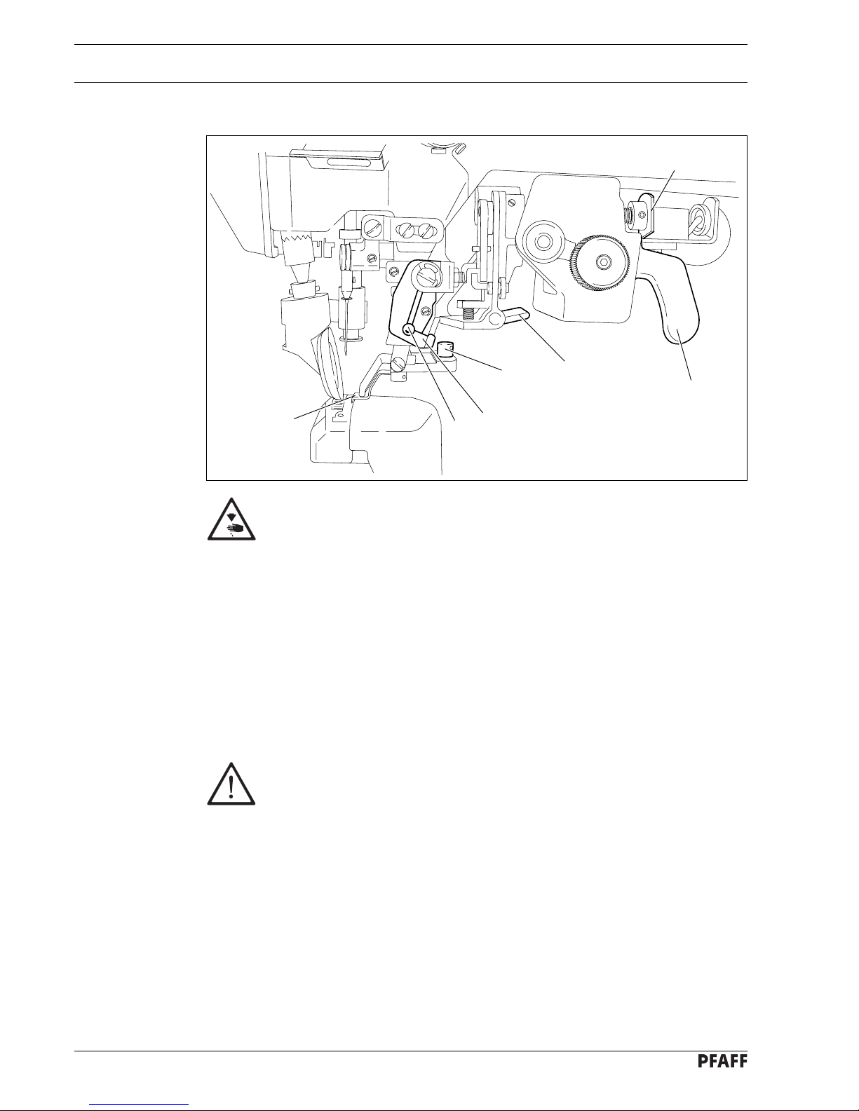
11.05 Adjusting the edge trimmer -725/04
11.05.01 Position of the knife holder on model 471
Requirements
When the thread trimmer is engaged and the adjusting wheel has been turned to its highest
position
1. the knife holder 2 must be parallel to the post and
2. the top edge of the needle plate must be in the centre of the angular knife opening.
● Turn the adjusting wheel 1 to its highest position and engage edge trimmer.
● Adjust knife holder 2 (screw 3) according to the requirements.
Fig. 11 - 31
1
2
3
Page 74

Adjustment
11 - 36
11.05.02 Position of the knife holder on models 474 and 491
Requirement
When the thread trimmer is engaged, the centre of the angular knife opening must be level
with the top edge of the needle plate.
Fig. 11 - 32
● Switch off the machine and engage the edge trimmer.
● Loosen screw 1.
● By turning sccentric 2, position the knife in the centre of its adjustment range.
● Adjust knife holder 3 according to the requirement and tighten screw 1.
● Position locking ring 4 on the knife holder 3.
Depending on the material thickness, changes in the basic setting of eccentric 2
are possible.
4
3
1
2
Page 75

Adjustment
11 - 37
3,5
Fig. 11 - 33
● Turn eccentric 1 (screws 2) so that the marking of the desired cutting stroke is opposite
the marking on clamp collar 3.
11.05.03 Knife stroke on model 471
Requirement
The knife stroke can be adjusted over a range from 1.0 to 3.5 mm, allowing the best
possible adaption to all materials used.
1
2
3
Page 76

Adjustment
11 - 38
11.05.04 Knife stroke on models 474 and 491
Requirement
The knife stroke can be adjusted over a range from 2.0 to 3.5 mm, allowing the best
possible adaption to all materials used.
1
3
2
-
+
Fig. 11 - 34
● Adjust crank 1 (nut 2) in slotted lever 3 according to the requirement.
Page 77

Adjustment
11 - 39
11.05.05 Cutting stroke on model 471
Requirement
When the edge trimmer is engaged and the needle is in the needle hole, the stroke of
knife 1 should be half in front of and half behind the needle, when the motor shaft is turned
by hand.
● Switch off the machine and engage the edge trimmer.
● Adjust knife 1 (screw 2) according to the requirement.
Fig. 11 - 35
1
2
1
½
½
Page 78

Adjustment
11 - 40
11.05.06 Cutting stroke on models 474 and 491
Requirement
When the edge trimmer is engaged and the needle is in the needle hole, the stroke of
knife 3 should be half in front of and half behind the needle, when the motor shaft is turned
by hand.
1
2
3
½
½
Fig. 11 - 36
● Switch off the machine and engage the edge trimmer.
● Adjust knife holder 1 (screw 2) according to the requirement.
Page 79

Adjustment
11 - 41
11.05.07 Knife position
Requirement
When the edge trimmer is engaged, the knife should rest lightly on the needle plate insert,
but no whistling sound should occur during trimming.
471
● Adjust screw 1 (screw 2) according to the requirements.
● Carry out a cutting test and repeat adjustment if necessary.
474 and 491
● Adjust knife 3 (screw 4) according to the requirements.
● Carry out a cutting test and repeat adjustment if necessary.
Fig. 11 - 37
1
2
4
3
Page 80

Adjustment
11 - 42
11.06 Adjusting the thread trimmer -726/05 on model 491
11.06.01 Position of the knife to the needle plate
Requirement
When the edge trimmer is engaged, the knife 2 must be parallel to the needle plate insert.
Fig. 11 - 38
● Switch off the machine and engage the edge trimmer.
● Loosen screw 1 and push back knife 2 slightly.
● Turn milled screw 3 until its top edge is flush with the top edge of the cylindrical guide 4.
● Loosen screw 5, position guide 6 in the centre of guide 7 and slightly tighten screw 5.
● Adjust knife holder 8 according to the requirement and tighten screw 5.
Screw 1 remains loosened for further adjustments.
7
3
6
5
4
1
8
2
2
Page 81

Adjustment
11 - 43
11.06.02 Knife position crosswise to sewing direction
Requirement
When the edge trimmer is engaged, knife 2 must be vertical and rest lightly on the needle
plate insert.
Fig. 11 - 39
1
2
3
● Switch off the machine and engage the edge trimmer.
● Bring the knife into a vertical postion by turning milled screw 1.
● Bring knife 2 into light contact with the needle plate insert and tighten screw 3.
The cutting pressure can be adapted to the material used with milled screw 1.
+
-
Page 82

Adjustment
11 - 44
11.06.03 Knife height
Requirement
When the edge trimmer is engaged, the centre of the angular knife opening must be at the
same height as the upper edge of the needle plate.
1
Fig. 11 - 40
● Switch off the machine and engage the edge trimmer.
● Adjust milled screw 1 according to the requirement.
The basic setting may be changed depending on the material thickness.
Page 83

Adjustment
11 - 45
11.06.04 Cutting stroke
Requirement
When the edge trimmer is engaged and the needle is in the needle hole, the stroke of
knife 3 should be half in front of and half behind the needle, when the motor shaft is turned
by hand.
Fig. 11 - 41
● Switch off the machine and engage the edge trimmer.
● Adjust knife holder 1 (screw 2) according to the requirement.
1
2
½
½
3
Page 84

Adjustment
11 - 46
11.06.05 Knife stroke
Requirement
The knife stroke can be adjusted over a range from 1.0 to 3.5 mm, allowing the best
possible adaption to all materials used.
Fig. 11 - 42
● Turn eccentric 1 (screws 2) on the back of the sewing head so that the marking of the
desired cutting stroke is opposite marking 3.
2
1
3
Page 85

Adjustment
11 - 47
11.07 Adjusting the thread trimmer -900/53
11.07.01 Removing the cutter
● Open post cover 1 and unscrew post cover plate 2 ( screws 3 ).
● Loosen screw 4.
● Swing out bobbin case base 5 by hand and hold it in this position.
● Remove bolt 6.
● Swing out the cutter driving rod and remove cutter 7.
● Allow bobbin case base 5 to swing in and push in the driving rod of the cutter.
Post cover plate 2 remains dismounted for further adjustments.
Fig. 11 - 43
1
3
3
2
4
5
6
7
Page 86

Adjustment
11 - 48
11.07.02 Control cam with respect to bobbin opener and tripping lever
Requirement
1. Control cam 2 must be touching bearing collar 3.
2. The roller of tripping lever 6 must fall slightly into the path of control cam 2.
5
4
2
6
1
7
3
Fig. 11 - 44
● Loosen screws 1 and bring control cam 2 to rest against bearing collar 3.
● In this position tighten one of the screws 1 slightly so that control cam 2 can still be
turned.
● Loosen screw 4.
● Position the straight section of the control cam underneath the roller of the tripping
lever 6.
● Move tripping lever 6 together with shaft 7 in accordance with requirement 2.
● Taking care to ensure that connecting link 5 engages completely in the groove of the rack,
bring connecting link 5 to rest on the right and tighten screw 4.
Only tighten screws 1 slightly for the following adjustment.
Page 87

Adjustment
11 - 49
11.07.03 Radial position of the tripping lever
Requirement
With the tripping lever 3 in resting position, there must be a clearance of 0.3 mm between
its roller and the circumference of the control cam 4.
Fig. 11 - 45
● Move solenoid carrier 1 (nuts of screws 2) in accordance with the requirement.
4
3
0.3 mm
2
1
Page 88

Adjustment
11 - 50
11.07.04 Engaging solenoid
Requirement
With the thread trimmer switched on, the magnet core must still be positioned at a
distance of 1 mm before its lower stop.
Fig. 11 - 46
● Bring the needle bar to BDC and activate the tripping lever by hand.
● Push solenoid housing 1 (screw 2) up as far as possible and then move it in accordance
with the requirement.
● Lift the tripping lever out of the control cam by hand.
2
1
Page 89

Adjustment
11 - 51
11.07.05 Cutter drive lever
Requirements
471 and 474
When the thread trimmer is in its resting position, the distance between cutter drive lever 4
and the bearing collar of the lever 5 must be approx. 0.5 mm.
491
The top edge of screw 1 must be approx. 9 mm from the recess of the cast case.
471 and 474
● Loosen nut 1 and screw out screw 2 a few times.
● Press lever 3 and screw in screw 2 by hand until a marked resistance is felt, during which
action lever 3 must not be raised.
● Screw in screw 2 half a turn more and tighten nut 1.
491
● Adjust screw 1 (nut 2) according to the requirement.
Fig. 11 - 47
1
2
3
4
5
1
2
0.5 mm
9 mm
Page 90

Adjustment
11 - 52
11.07.06 Control cams for bobbin opener and cutter
(using adjustment gauge)
Requirement
With the needle bar at BDC, both control cams must be positioned in such a way that
1. adjustment gauge 5 can be slid into the grooves of both control cams,
2. both cams are on the rests of adjustment gauge 5 and
3. the bent section of adjustment gauge 5 is touching roller 3.
1 2
4
5
3
Fig. 11 - 48
● Loosen screws 1 and 2.
● Bring the needle bar to BDC and activate the tripping lever by hand ( roller 3 engaged ).
● Adjust the control cams in accordance with the requirement and insert adjustment
gauge 5.
● Turn control cam 4 in accordance with the requirement.
● Taking care to ensure that control cam 4 is touching the bearing collar, tighten the
accessible screws 1 and 2.
● Remove adjustment gauge 5 and tighten the remaining screws 1 and 2.
For adjustment without the gauge see chapter 11.07.07 Radial position of the
control cam in relation to the bobbin opener and chapter 11.07.09 Cutter
control lever for control cam of cutter.
Page 91

Adjustment
11 - 53
11.07.07 Radial position of the control cam in relation to the bobbin opener
(adjustment without gauge)
Requirement
The retracting motion of the bobbin opener must begin when the needle bar is 4 mm after
BDC.
1
2
3
Fig. 11 - 49
● Activate the tripping lever by hand. The roller of the tripping lever 1 must fall easily and
unobstructed in to the cam track.
● Loosen screws 2.
● Bring the needle bar to 4 mm after BDC ( use adjustment gauge and C-clamp ).
● Turn control cam 3 in the direction of rotation until you feel resistance ( start of the
retracting motion ).
● In this position tighten the accessible screw 2.
● Remove tripping lever 1 out of the control cam 3 by hand.
● Remove the C-clamp and tighten the remaining screw 2.
Page 92

Adjustment
11 - 54
11.07.08 Control cam for cutter (adjustment without gauge)
Requirements
1. The cutting movement must begin when the needle bar is positioned 0.6 mm past TDC.
2. There must be a distance of 9 mm between control cams 2 and 4.
● Loosen screws 1.
● Bring needle bar to BDC and operate the engaging lever by hand.
● Bring the needle bar to 0.6 mm past TDC (use adjustment gauge and clamp).
● Turn control cam 2 until the cam is resting on the cylinder of control lever 3.
● Making sure that control cam 2 is at a distance of 9 mm to sliding cam 4, tighten one of
the screws 1.
● Remove clamp, make second screw 1 accessible and tighten it.
When using elastic thread it may be necessary to adjust the control cams for the
bobbin opener and cutter a little "later".
For very elastic threads a thread tension control device (subclass 906/10) for
automatic tension release is available.
4
1
2
3
Fig. 11 - 50
9 mm
Page 93

Adjustment
11 - 55
11.07.09 Cutter control lever for the control cam of the cutter
Requirements
At the left point of reversal of the rock shaft 3
1. the cylinder of control lever 4 and of reversing lever 5 must be positioned at the centre
of the control cam 6;
2. between the cylinder of control lever 4 and the outer diameter of the control cam 6
there must be a distance of 0.3 mm.
6
5
2
4
3
1
0.3 mm
6
4
Fig. 11 - 51
● Bring needle bar to BDC and operate engaging lever by hand.
● Loosen screws 1 and 2.
● Turn balance wheel in turning direction, until rock shaft 3 is in its left point of reversal.
● Adjust control lever 4 and reverse lever 5 according to requirement 1.
● Turn control lever 4 according to requirement 2.
● In this position and taking requirement 1 into consideration, tighten screw 1.
Screw 2 remains loosened for later adjustments.
Page 94

Adjustment
11 - 56
11.07.10 Cutter return lever
Requirement
When the roller of tripping lever 3 is exactly at the point of the trip of control cam 2 the
maximum distance between the roller of return lever 4 and control cam 2 must be 0.2 mm.
● Bring the needle bar to BDC and activate the engaging lever by hand.
● Position the point of the trip of control cam 2 exactly at the middle of the roller of tripping
lever 3 by turning the handwheel in the direction of sewing.
● Maintaining this position, bring the return lever 4 to rest against the side of tripping
lever 3 and turn it radially in accordance with the requirement.
● Tighten screw 1.
3
1
4
2
Fig. 11 - 52
2
4
max. 0.2 mm
Page 95

Adjustment
11 - 57
11.07.11 Cutter return control
Requirement
1. When the point of the trip of control cam 1 is exactly at the roller of tripping lever 2 and
trip 3 is touching the beginning of the angular edge of guide plate 5 (see arrow), there
must be a clearance of approx. 0.6 mm between trip 3 and guide plate 5.
2. When the rock shaft has sprung back to its starting position the maximum clearance
between trip 3 and guide plate 5 must be 0.3 mm.
3
5
1
2
0.6 mm
4
1
2
0.3 mm
Fig. 11 - 53
● Position the point of the trip of control cam 1 exactly at the roller of tripping lever 2 by
turning the handwheel.
● Move trip 3 ( screw 4 ) in accordance with requirement 1.
● Bring rock shaft back to its starting position.
● Check requirement 2. If necessary, position guide plate 5 appropriately.
Page 96

Adjustment
11 - 58
11.07.12 Fitting the cutter
Requirement
1. The pin of bolt 4 must protrude into the cam tracks of the cutter halves.
2. The cutter must work with as little lateral play as possible.
● Swing out driving rod 1.
● Swing out bobbin opener 2 by hand and hold it.
● Insert the cutter with its bearing pin 3 into the bearing bushing of the feed wheel post.
● Swing in driving rod 1 and insert pin 4 in accordance with requirement 1.
● Position the eccentricity of pin 4 so that it faces upwards.
● Tighten screw 5 and screw on the post cover plate.
● Check driving rod 1 for play and friction-free running. If necessary, adjust with screw 6
(nut 7).
For model 474 repeat adjustment on the right post.
Fig. 11 - 54
1
2
5
4
6
7
3
4
Page 97

Adjustment
11 - 59
11.07.13 Eccentric sleeve
Requirement
1. In its starting position the cutter must be flush with the contour of the needle plate.
2. The cutter must lightly touch the needle plate and the eccentric sleeve 2.
● Loosen screw 1 enough so that eccentric sleeve 2 can still be turned.
● Turn eccentric sleeve 2 until the cutter is flush with the needle plate.
● Maintaining this position, move eccentric sleeve 2 laterally in accordance with the
requirement.
● Tighten screw 1.
● Press pin 3 (screw 4) lightly against the scissor.
For model 474 repeat adjustment on the right post.
Fig. 11 - 55
4
3
2
1
2
1
PFAFF 491
Page 98

Adjustment
11 - 60
11.07.14 Cutter driving rod
Requirement
1. In its starting position the cutter must be flush with the needle plate contour.
2. At the TDC of the driving rod 2 there must be a safety clearance of at least 0.3 mm
between pin 5 and the top end of the cam guide.
● Bring the needle bar to BDC and activate the engaging lever by hand.
● Bring driving rod 2 to its top point of reversal by turning the handwheel.
● Carry out the alteration on the driving rod 2 (screw 1), the eccentric sleeve 3 (screw 4)
and/or the eccentric pin 5 (screw 6) in accordance with the requirement.
● Check the requirement from chapter 11.07.13 Eccentric sleeve.
● Bring the thread trimmer to its starting position using the handwheel.
If using the 474 model, carry out the same adjustment on the second post.
5
2
6
3
4
Fig. 11 - 56
5
0.3 mm
3
4
PFAFF 491
1
Page 99

Adjustment
11 - 61
11.07.15 Cutter function test
Requirement
1. The threads must be cut neatly.
2. After being trimmed, the bobbin thread must be held securely by the thread trapper.
Fig. 11 - 57
● Turn the machine on.
● Sew a few stitches and turn the on/off switch off.
● Activate the engaging lever by hand and close the post cover while ensuring that pressure
disk 1 is inserted into the post cap.
● Bring the needle bar to TDC by turning the handwheel and open the post cover.
● In this position the needle and bobbin threads must be held by the catching lug 2 of bobbin
case and the needle thread must be held by the catching lug 3 of bobbin.
● If the needle thread is not held, insert a new pressure disk 1 (part no. 91-119 492-91).
● Turn the handwheel and observe the cutting process.
4
2 3
1
Page 100

Adjustment
11 - 62
● When the cutter is moving forward, the thread trapper must first trap and hold the threads
reliably on the cutter (if necessary adjust the thread trapper as required after loosening
retaining screw 4).
● As the process continues, both the bobbin thread and the part of the thread loop closest to
the cutter, which is held by the catching lug must be cut perfectly.
● If the threads are not cut at all or not cut fully, check the chapter 11.07.14 Cutter driving
rod again.
● Carry out a check according to the requirement.
 Loading...