

Page 1
PFAFF
436
One
G. M. PFAFF AG, Sewing Machine Factory, KAISERSLAUTERN
y
>/-
•
Needle
with
Locksfifch
Automatic
INSTRUCTION
Superspeed
Lubrication
BOOK
Sewer
Page 2
Ind
ex
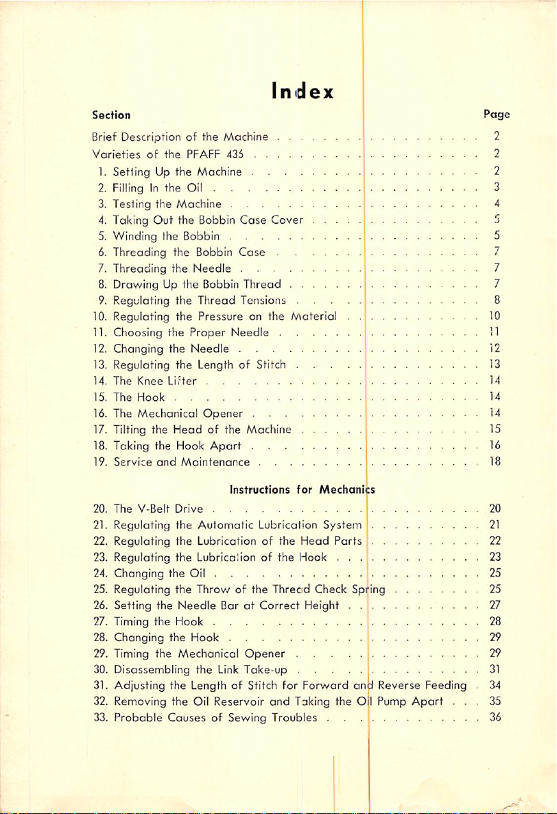
Section
Brief Description of the Machine
Varieties
1.
of
the
SettingUpthe
PFAFF
Machine
435
2. Filling In the Oil
3.
Testing
4. Taking
5.
Winding
Threading
6.
7.
Threading
8. Drawing Up the Bobbin
9.
Regulating
the
Qjt
the
the
the
Machine
the Bobbin
Bobbin
Bobbin
Needle
the
Thread
Case
Cover
Case
Thread
Tensions
. . .
.
10. Regulating the Pressure on the Material
11. Choosing the
12. Changing the
13.
Regulating
14.
The
Knee
15.
The
Hook
16. The
Mechanical
17. Tilting the
18. Taking
19.
Service
Lifter
the
and
Proper
Needle
Needle
the
LengthofStitch .
Opener
Head
of the Machine . . . .
Hook
Apart
Maintenance
Page
2
2
2
3
10
11
12
13
14
14
14
15
16
18
Instructions
20.
The
V-Belt
Drive
21.
Regulating
the
Automatic
22. Regulating the Lubrication of the
23. Regulating the Lubricalion of the Hook . . .
24.
Changing
the
Oil
for
Lubrication
Head
Mechanics
System
Parts
20
21
22
23
25
25. Regulating the Throw of the Threcid Check Spring 25
the
Needle
Hook
26. Setting the
27. Timing
28. Changing the Hook
29. Timing
30.
Disassembling
the
Mechanical
31. Adjusting the Length of Stitch for Forward and Reverse Feeding
32. Removing the Oil Reservoir
33.
Probable
Causes
BaratCorrect
Opener
the
Link
Take-up
and
of Sewing Troubles .
Height .
....
....
Taking the Oil Pump
Apart
27
28
29
29
31
34
35
36
Page 3
Instruction
Book
One
This
operators
made
Needle
Instruction
available to both
PFAFF
Lookstifch
with
Automatic
Book
contains
and mechanics alike and therefore should be
rather
436
Superspeed
Lubrication
useful
than
instructions
put away In your files.
Sewer
for
Page 4
PFAFI=
Brief
Descrlpfion
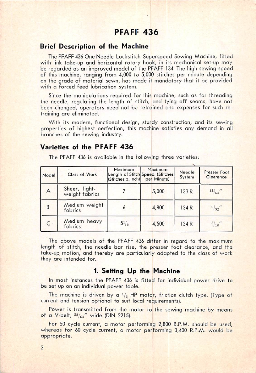
The PFAFF436
with link
take-up
One
and
of
the
Needle
horizontal
Machine
Lockstitch
be regarded as an improved model of the
of this machine, ranging
on the
grade
withaforced
of material sewn, has mode it
feed
from
lubrication
4,000 to 5,000 stitches
system.
436
Superspeed
rotary
hook, in its mechanical set-up
PFAFF
mandatory
Sewing Machine,
134.
The high sewing speed
per
minute
that
it be provided
depending
Since the manipulations required for this machine, such as for threading
the needle, regulating the length of stitch,
been
changed,
training
With its
properties
branchesofthe
are
eliminated.
modern,
of highest
operators
functional design,
perfection,
sewing
industry.
need not bs retrained
this machine
sturdy
and
tying
and
construction,
satisfies
off
seams,
expenses
any
for such re
and
its
demand
have
fitted
may
not
sewing
in all
Variefies
The PFAFF 436 is
Model
A
B
C
The
length of stitch, the
take-up motion,
they
In
be
set
off
the
PFAFF
availoble
ClassofWork
Sheer,
weight
Medium
fabrics
Medium
fabrics
above
light
fobrics
weight
heavy
models of the
needle
and
are
intended
thereby
for.
1.
most
instances the PFAFF 436 is
up on on individual
Maximum
Length
(Stitches p.
bar
are
Setting
power
436
in the following
of Stifch
7 5,000
6 4,800
5'/,
PFAFF
Maximum
Speed
Indit
per
436 differ in
rise, the
particularly
Up
the
fitted
table.
three
(Stitches
Minute)
4,500
presser
adapted
Machine
for individual
varieties:
Needle
System
133
134
134
regard
foot
clearance,
Presser
Clearence
R
R
R
to the maximum
to the class of work
power
''Ua"
The machine is driven by a '/» HP motor, friction clutch type. (Type of
current
and
tension
optional
to suit local requirements).
Power is transmitted from the motor to the sewing machine by
of a V-belt,
For 50 cycle current, a
whereas
appropriate.
2V0.1"
wide
(DIN 2215).
motor
for 60 cycle current, a
performing 2,800 R.P.M. should be used,
motcr
performing 3,400 R.P.M. would be
Foot
"/ic '
and
drive to
means
the
Page 5
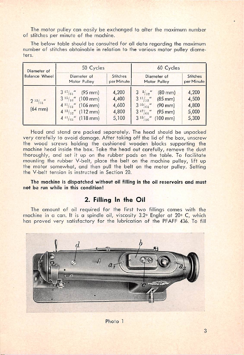
The
motor
pulley
per
of stitches
The below
minute of the machine.
table
number of stitches
ters.
can
easilybeexchangedtoalter
should be consulted for all
obtainable
in relation to the
the maximum number
data
regarding the maximum
various
motor
pulley
diame
Diameter
Balar^ce
(64 mm)
Head
very
of
Wheel
and
carefully lo
50 Cycles 60
Diameter
Motor
Pulley
3'Vei"
3'"/ic"
(95 mm)
(100mm)
4'Vg4" (106 mm)
4%2"
(112mm)
4 (118 mm)
stand
are
avoid
packed
damage.
of
Stitches
per
Minute
4,200
4,400
4,600
4,800
5,100
separately.
After
taking
Diameter
Motor
3 (80 mm)
3'Vn2"
3
35/^,,"
3^'/c.i" (95 mm)
3";ic"
The
head
off
the lid of the
Cycles
of
Pulley
(85 mm)
(90 mm)
(100 mm)
should be
box,
Stitdies
per
Minute
4,200
4,500
4,800
5,000
5,300
unpacked
unscrew
the wood screws holding the cushioned wooden blocks supporting the
machine
thoroughly,
mounting the
the motor
the
not
machine in a can. It is a spindle oil, viscosity 3.2° Engler
has
head
inside the box. Take the
and
set
rubber
somewhat,
V-belt
tensionisinstructed
The
machineIsdispatched
be
run
whileinthis
The
amount
proved
of oil
very
it up on the
V-belt,
and
condition!
2.
required
satisfactory
head
rubber
place
the
than pull the
in
Section
without
oil filling in
Filling In
for the first
out carefully,
pads
belt
on the machine pulley, lift up
belt
on the motor pulley. Setting
20.
ihe
Oil
two
for the lubrication of the
on the
the
fillings
table.
oil
reservoirs
remove
To
comes
at
20° C, which
PFAFF
the
dust
facilitate
and
must
with the
436. To fill
Photo
1
Page 6
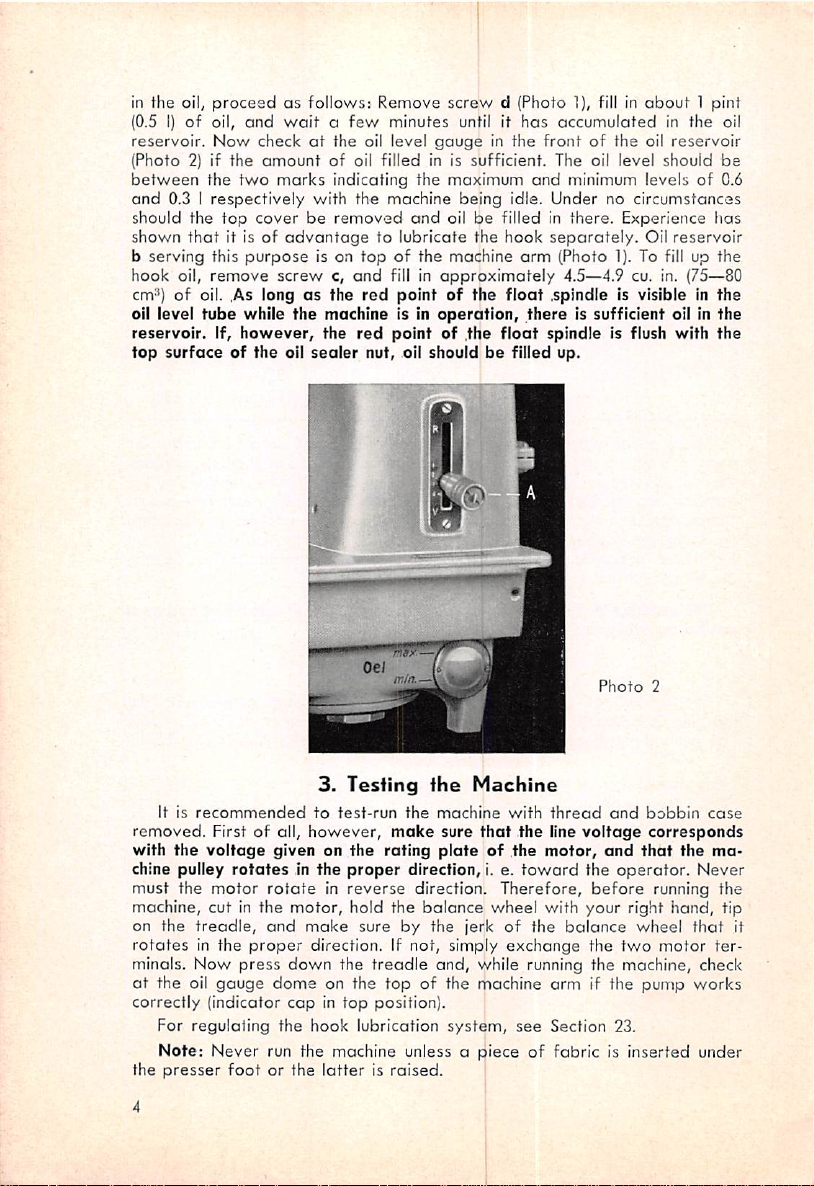
in the oil,
(0.51)of
reservoir.
(Photo 2) if
between
and
should the
shown
b
serving
hook oil,
proceedasfollows: Remove
oil,
and
Now
checkatthe
the
amountofoil filled in is sufficient. The oil level
the
0.3 I
two
respectively
top
that
coverberemoved
it isofadvantagetolubricate
this
purpose
remove
cm^) of oil. ,As long
oil level
reservoir.
top
tube
surface
while
If,
however,
of the oil
waitafew
marks
with
is on
screwc,and
as
the
machine is in
the
sealer
minutes
oil level
indicating the maximum
the
machine
topofthe
fill in
the
red
red
pointof.the
nut, oil should be filled up.
screw
d (Photo 1), fill in
until it
gaugeinthe
being
and
oil be filled in there. Experience fias
machine
approximately
point
of the
operation,
the
has
accumulatedinthe
frontofthe
and
minimum levels of 0.6
idle.
Undernocircumstances
hook
separately.
arm
(Photo
1). To fill up
4.5—4.9 cu. in. (75—80
float
.spindle is visible in
there
float
is sufficient oil in the
spindle
is flush
about
oil
should
Oil
1 pint
reservoir
reservoir
the
the
with
the
oil
be
3.
Testing
It Is
removed.
with the
chine pulley
must the
recommended
First of all,
voltage
rotates
motor
machine, cut in the
on the
rotates
minals.
ot the oil
treadle,
in the
Now
gauge
proper
press
correctly (indicator
to
test-run
however,
given on the
in the
proper
rotateinreverse
motor,
and
hold the
make
sure by the jerk of the
direction. If not, simply
down
the
dome on the top of the machine arm if the pump
capintop
For regulating the hook lubrication
Note:
the
Never run the machine unless a piece of fabric is inserted under
presser
footorthe
latterisraised.
the
Machine
the
machine
make
sure
rating
plateofthe
direction, i. e.
direction. Therefore,
balance
treadle
and,
while running the machine, check
position).
system,
Photo
with
that
thread
the
line
motor,
toward
and
voltage
and
the
operator.
before
wheel with your right
balance
exchange
see
the
Section 23.
two
2
bobbin
corresponds
that
the
Never
running the
hand,
wheel
that
motor
works
case
ma
tip
it
ter
Page 7
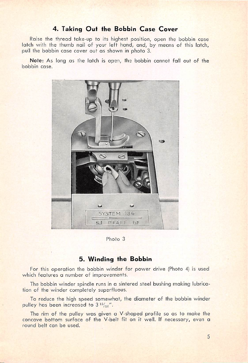
4.
Raise the
Taking
thread
Ouf
take-up
fhe
to its highest position,
latch with the thumb nailofyour
bobbin
case
cover
pull the
Note:
bobbin
As long as the latch is
case.
outasshown in
Bobbin
left
open,
Case
hand,
and,bymeansofthis lotch,
photo
the bobbin
iilTiTIM
3.
Cover
open
cannot
the
fall
bobbin
out
case
of the
5.
Winding
For this
which
operation
featuresanumberofimprovements.
the bobbin winder for
SYSTEM
Photo
the
ISA-
3
Bobbin
power
drive (Photo 4) is used
The bobbin winder spindle runs in a sintered steel bushing making lubrica
tion of the
To reduce the high
pulley
The rim of the pulley
concave
round
has
been
bottom
belt
canbeused.
winder
completely
speed
increased
surface
superfluous.
somewhat,
to
was
given a V-shaped profile so as to
of
the
V-belt
the
fit
diameter
on it
well.Ifnecessary,
of the bobbin winder
make
even
the
a
Page 8
hjLv
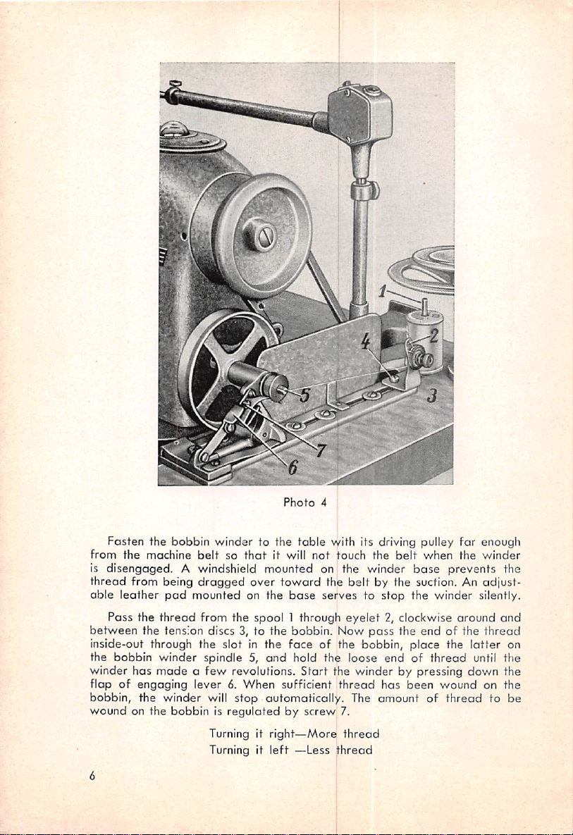
Photo
4
Fasten
the
from
the
bobbin
machine
belt
winder
so
to the
thatitwill
table
with its driving pulley for enough
not
touch
the
is disengaged. A windshield mounted on the winder
thread
from being
oble leather
Pass
between
the
the tension discs 3, to the bobbin. Now
inside-out through the slot in the
the
bobbin
winder has
flap of engaging lever 6. When sufficient
bobbin, the wincier will
wound
on the
dragged
pad
mounted on the
thread
from the spool 1 through
over
toward
base
face
winder
madeafew
spindle 5,
revolutions.
stop
and
hold the loose
automatically. The amount of
bobbinisregulatedbyscrew
Turning it
Turning it
right—More
left
—Less
the belt by the suction. An adiust-
serves to
eyelet
stop
2, clockwise
pass
of the bobbin, place the
endofthread
Start
the winder by pressing down the
thread
has
7.
thread
thread
belt
when
base
the
prevents the
the winder silently.
around
the end of the
latter
until the
been
wound on the
thread
winder
and
thread
on
to be
Page 9
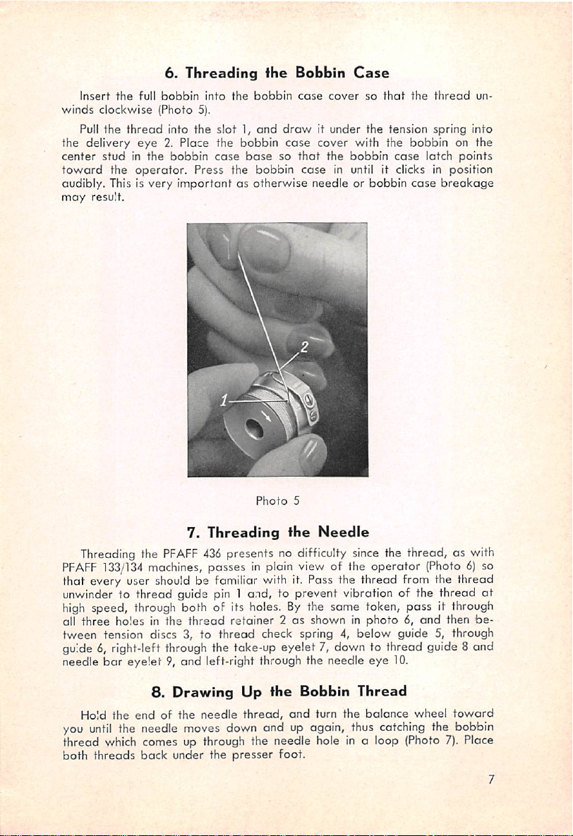
6.
Threading
Insert
the
full
winds
clockwise
Pull
the
the delivery
center
stud
toward
audibly. This is very innportant
may
the
result.
bobbin
(Photo 5).
thread
eye
in the
operator.
into
into the slot 1,
2. Place the bobbin
bobbin
case
Press the
ihe
the
bobbin
and
basesothat
bobbin
as
otherwise
Bobbin
case
draw
case
case
Case
cover
so
that
it under the tension spring into
cover with the bobbin on the
the
bobbin
in until it clicks in position
needle or
case
bobbin
the
case
thread
latch
breakage
un
points
Photo
5
7.
Threading the
PFAFF
133/134
Threading
PFAFF
436
machines, passes in plain view of the operator (Photo 6) so
presents no difficulty since the thread, as with
fhe
Needle
that every user should be familiar with it. Pass the thread from the thread
unwinder to thread guide pin 1 and, to prevent vibration of the thread
high
all
speed,
three
through
holes in fhe
both of its holes.Bythe same token, pass it
thread
retainer2as
showninphoto6,and
through
then
be
tween tension discs 3, to threod check spring 4, below guide 5, through
guide 6, right-left through the take-up eyelet 7, down to thread guide 8 and
needle
bar
eyelet
you
9, and left-right through the needle
8.
Drawing
Hold
the
until
endofthe
the needle moves down and up again, thus catching the bobbin
needle
Up
thread,
the
Bobbin
and
turn
Thread
the
eye
balance
10.
wheel
toward
thread which comes up through the needle hole in a loop (Photo 7). Place
both
threads
back
under the
presser
foot.
at
Page 10
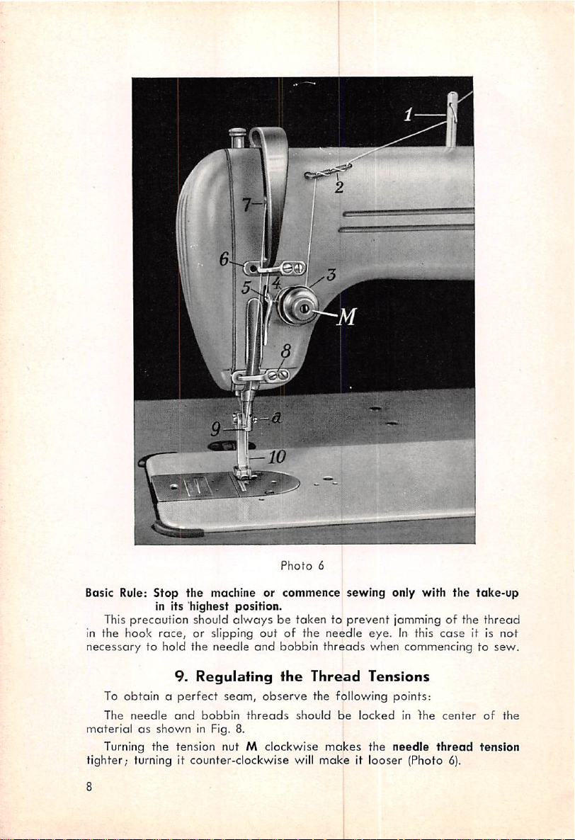
Photo
6
Basic Rule:
This
in the hook
necessary
To
The
materialasshown
Stop
the machine or
in its
race,
highest
should
or slipping
precaution
to hold the
9.
Regulating
obtainaperfect
needle
and
bobbin
in Fig. 8.
position.
alwaysbetakentoprevent
out
needle
and
seam,
observe
threads
Turning the tension nut M clockwise
tighter;
8
turning it
counter-clockwise
commence
of the
bobbin
the
sewing
needle
threads
Thread
the following points:
should
be
makes
will
makeitlooser
only with the
jamming of the
eye.
when
Tensions
locked
the
needle
In this
case
commencing to
in
fhe
center
thread
(Photo
6).
take-up
thread
it is no't
sew.
of
the
tension
Page 11
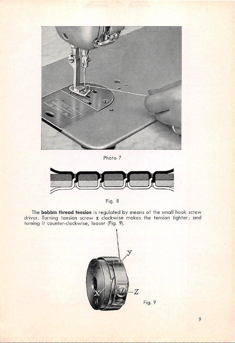
Photo
Fig. 8
7
The bobbin
thread
tension is regulated by means of the small hook screw
driver. Turning tension screw z clockwise mokes the tension tighter;
turning it
counter-clockwise,
looser
(Fig. 9).
Fig. 9
and
Page 12
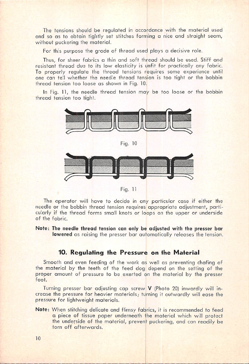
The tensions should be reguloted in accordance with the material used
and so as to obtain tightly set stitches forming a nice and straight seam,
without
resistant
To
one
thread
thread
needle
cularly if the
of
Note: The needle
puckering the
For this purpose the
Thus, for
properly
can
In Fig. 11, the
The
sheer
thread
tell
whether
tension
tension
operator
or the
fabrics
due
regulate
too
looseasshown
needle
too
tight.
will
bobbin
thread
the
fabric.
thread
loweredasraising the
material.
gradeofthread
a thin
low
thread
needle
and
elasticity
to its
the
the
thread
have
to decide in any particular
thread
tension
used plays a decisive role.
soft
thread
should be used. Stiff
for
requires
be
appropriate
tensions
thread
in Fig. 10.
tension
Fig. 10
Fig. 11
requires
is unfit
tensionistoo
may
practically
some
tightorthe
too
loose or the
any
experience
case
if either the
adjustment,
and
fabric.
until
bobbin
bobbin
parti
forms small knots or loops on the upper or underside
tension can only be
presser
bar
adjusted
automatically
with the presser
releases
the tension.
bar
10.
Smooth
Regulating
and
even
feeding
the
of the
Pressure
work
on
the
Material
as wellaspreventing
chafing of
the material by the teeth of the feed dog depend on the setting of the
proper
foot.
crease
pressure
Note:
10
amountofpressure
Turning
presser
bar
the pressure for heavier
for
lightweight
When
stitching
a piece of tissue
adjusting
materials.
delicate
paper
to be
exerted
cap
materials;
and
flimsy fabrics, it is
underneath the material which will
the underside of the moterial, prevent
torn
off
afterwords.
on the
material
by the
presser
screw V (Photo 20) inwardly will in
turning it outwardly will
ease
the
recommendedtofeed
protect
puckering,
and can readily be
Page 13

11.
Choosing
Standard
are
used with the
short
System 134R, which
is imprinted on the needle
needles,
round-shank
PFAFF
System
133 R,
are
needles
436. Model A mochines for sheer fabrics require
wropper.
fhe
with round point
whereos
ModelBand
longer. The
Proper
standard
Needle
and
C machines use
shank
diameter
shank
The needle is of eminent importance for obtaining a perfect seam
therefore should be chosen in
weights
used.
proper
relation to the
thread
and
For lightweight fabrics, a thin needle should be used to prevent ugly
needle
marksinthe
When using a thin needle with a thick thread, the
to breok, ond, conversely, when using thin
pingofstitches
Select the
may
proper
fabric.
occurasa
needle
result.
from the
chart
thread
below:
thread
in a thick needle, skip
diameter
needles,
of
and
fabric
is likely
Needle
Size
Cotton
70
Silk,
75
Silk,
Cotton
80
Silk,
85
Silk, genuine 80/3
Cotton
90
Silk,
Silk, genuine 70/3 (C)
Note:
We
wrapper
Machines"
Never
use
Only fhe
free
sewing
PFAFF 436, a
thread.
the
to
heat
and
Needle
Thread
short
genuine
short
short
warn
Weight
fiber 100/3
fiber 80/3
fiber
youtouse
should
bear
plus the
rusty
needles!
exceptional
and
needle
quality
prevents
with a rough
This is particularly
melts
easily.
and
Thread
Needle
Size
100-80
100
100/3(0)
80-60
110
(B)
60-40
70/3
120
needlesofunknown
the inscription
needle
system.
of the finish of the
thread
breaking.
surface
true
of Nylon
Chart
Thread
Cotton
Silk,
short
fiber
Silk, genuine 60/3
Linen
thread
Cotton
Silk,
short
fiber
Silk, genuine 50/3
Linen
thread
Cotton
Silk,
short
fiber 40/3
Silk, genuine 40/3
Linen
thread
origin
"Needles
evenifthe
for
needle
Due to the high
gets
hot
quickly
thread
which is
Weight
40-30
60/3
90-80
30-24
50/3
80-50
30-16
60-40
Pfaff
ensures
speed
and
very
(D)
(E)
needle
Sewing
trouble-
of the
thus burns
sensitive
11
Page 14

If the
rial or
standard
running
needle
shoyld
get
too hot
when
stitching in
dense
mate
the machine for a longer time, it is recommended to ex
change the ordinary needle for a mirror-finished, chromium-coated high
efficiency needle, Systems 133 or
12.
Changing'the
1.
Raise
the
needle
bar
to its
2. Loosen the
3.
Pull
out
the
needle
needle.
set
screw
134,
which
may be procured from us.
Needle
highest
position.
o (Photo 6) with the small
screw
driver.
•,^i
Photo
12
12
Page 15

4. Insert
5. Tighten the
which con be
(Photo 2). A special device locks the length of stitch
be
the length oF stitch in miLimeters. Through pushing the stitch
up
by
tically return to its initial position. The
new
needle,
right
end
push it upasfarasit will go.
The PFAFF 436 is
changed
as
Shifting the machine to
foot
set
inadvertently
farasit will go, the machine is
control.
Systems
needle
set
screw
13.
Regulating
fitted
for the length of stitch
After
with the
while sewing. The numbers on the scale
reverse
letting go of the stitch
133 R or 134 R, with the
a firmly.
ihe
Lengfh
proved
desired
set
stitching can
treadle
of
spring-activated
by turning the thumb nut A
for
reverse
eitherbedonebyhand
regulator
for the stitch reversing device
short
Stitch
setsothat
feeding.
lever, it will
groove
stitch
regulator
it cannot
regulator
facing
indicate
lever
or
automa
Photo
/
13
13
Page 16

is arrangedatthe left to relieve the right leg which has to
actuate
the knee
lifter. Through this device both hands are free to manipulate the work
(Photo
12}.
14.
The
Knee
The PFAFF 436 is
connected
with
the
heodofthe
fitted
withaknee
machine.
The presser foot is either lifted by raising the
or by actuating the knee lifter with the right knee. The knee lifter
be
adjusted
screwband
(Photo 13). To permit tilting the
knee
lifter can be pulled
can
easilybereached
The
twice
is
that
The hub of the hook
being properly
horizontally
adjustatscrew
through an opening in the
PFAFF
per
436 is fitted with the
cycle. The only difference
the
PFAFF
436 hook is provided with centrifugal lubrication.
shaft
balanced,
and
vertically. For horizontal
a;
for
head
off
after
pulling
15.
The
is provided with an oil
ensures an absolutely vibrationless running of the
hook. The oil emerging from a hole in the hook
by centrifugal force
and
then enters the hook race through a second
Lifter
lifter
device
presssr
vertical
adjustment,
back, the knee lifter
out
piston pin d (Photo 18) which
dress
Hook
proved
between
hook of Model 134, rotating
previous models and this one
shaft
which is
bar
adjustment,
guard.
retainer
bushing is
harmoniously
lifter by hand,
pad
loosen
shaft
loosen
screw
with the
ring which,
atomized
can
bore
where it effects a dependable and permanent lubrication.
The amount of oil,
can be regulated
This
job, however,
set
after
for
removing the needle
should
only
average
sewing requirementsatthe factory,
plate
be performed by a
as instructed in Section 23.
mechanic.
c
16.
The
Mechanical
All varieties of the
Since the
like to
advantages
addafew
With a lockstitch machine the locking of the needle
is
doneintwo
as with oscillating or vibrating shuttle machines, the
PFAFF
of this device
explanations here.
different
ways,
436
are
depending
fitted with positive mechanical opener.
Opener
are
not generally known,
and
on the class of machine. Either,
threads
bobbin
are
we
should
threads
locked by
passing the bobbin thread in a shuttle through the needle thread loop which
has
been
formed while the needle, having
passed
the lowest point of its
downward stroke, is rising, or by passing the needle thread loop around
the bobbin case with the latter being in a stationary position.
14
Page 17

In
machines having oscillating loop takers, such as central bobbin ma
chines,
needle thread loop around the
the loop
forming
part,
while
bobbin
moving
back and forth, passes the
case with the latter being mounted
in a cenfral or eccentric position.
With
horizontal hook rototing twice per cycle,
which
the needle thread loop ispassed around the stationary
other
the type of loop taker generally used for
revolutionofthe
hook.
high
speed sawers, the
isalso usedinthe
bobbin
case at every
PFAFF
436,
With rotary hook machines, having no mechanical opener, the needle
thread, after having been passed around the bobbin case, has to turn the
bobbin case slightly making an opening through
With the increasing
sewing
speed
the friction
which
between
it can pass.
the hook
race
and the bobbin case increases accordingly and causes the bobbin case stop
to increase its pressure on the bobbin case position finger. As a result, the
needle thread has to overcome a stronger resistance when passing between
the stops.
This
intensified strain, in turn, can only be overcome by easing
the thread tension to prevent thread breaking.
The
needle thread tension has to be
drawback
setting of stitches impossible if the machine is
To eliminate
o mechanical
opener
at
This
finger
speed
changed,
exposed
shaft
the
proper
way
the needle
and
sewers
irregardless
to additional or evar-changing strain. As a result,
fabrics the
stitches
threads
high sewing
eliminated.
become
top
of
mechanical
as
and
of a low tensile strength
completely
speed.
All of the
the PFAFF 436
Timing of the mechanical
instructed
of this remedy lies in the
eased
fact
that
in most
cases
to an extent which makes proper
operatedatreduced speed.
these
disadvantages,
opener,
whereby
PFAFF High
a small lever
Speed
mounted
Sewers
are
on the mechanical
fitted
assumes the function of moving the bobbin case back sligthly
moment
the
bobbin
are
thread
and
thread
manifold.
contrary
is permitted to
case
stop.
of the
First
sewing
tensions can be
to the
rotating
pass
The
advantages
the
needle
spead,
set
since the
so as to ensure even setting of the
direction of the hook.
freely
between
of this device for high
thread
tension
needle
need
threadisnot
also
the position
not
for
to prevent puckering of the materialatall speeds. Second,
may
be
used
speeds
Third,
above
opener.
in
Section
since the
also
smooth
advantages
intended
dangerofthread
while
the
yet,
account
for heovier
opener
29.
bearing
the
should only be
surfaces
machins
for the
materials
on this machine
breaking
will
fact
are
performed
has
of
the
sew
flimsy
that
also
fitted
with the positive
even
greatly
hook
have
fabrics
the
varieties
by a mechanic
the
with
be
sheer
for
been
not
at
dog
knee
17.
Tilfing
To
facilitate
and
lifter.
the
the hook, the machine can be tilted
removaloflint
fhe
Head
having
of
the
accumulated
Machine
back
after
between
taking
the,feed
off
the
15
Page 18

For
this
under
purpose,
the table and
lifter with the knee lifter shaft can be pulled out at the front. Having done
reach
through
pull
back the piston
the
holeinthe
middle
pind(Photo
of the dress guard
18).
Then
the knee
this, the head can be tilted back and rested on the wooden machine rest
or on the sew light bracket
after
the latter has been swung off.
18. Taking
Skilled
operators who make it a routine to start or
the
Hook
Apart
finish
a seam only
with the take-up in its highest position, or to place the threads back under
the presser foot when commencing to sew,
jamming in the hook
Should thread jamming occur, however, first try to get a hold of the
loose end and to
If this
attempt
race.
pu-l
it out while jerking the balance wheel back and forth.
fails,
take
the hook
will
hardly ever encounter thread
apart,
proceeding as follows:
Photo
14
16
Page 19

1.
Tilt
the
head
backasinstructedinSection
2. Raise
the
needle
still be turned. If not,
(Photo 14) first.
3. Loosen
set
screw c and pull off the mechanical opener lever b. When
reassembling the
on the
shaft
groove.
4. Pull
out
with
thumb
5. Raise the
6. Loosen
can easily be reestablished since the
the bobbin
and
head
screws,
bar
and
the
remove
parts,
the
cose
forefinger.
cover
of the machine
e„
e®,
and
O;)
take-up,
the
bobbin
proper
with the bobbin, seizing it by the latch
and
(Photo 15)
17.
provided
case
position finger
position of the mechanical
remove
needle
and
take
which, however, should not be confused with the hook
the
balance
shaftismarked
plate
and
off
the hook gib d
body
wheel
bracket
opener
feed
guard
can
a
by a
dog.
f.
Photo
15
7. Turn the
balance
wheel
until the
first
screw
is opposite notch I in the bobbin case (Photo
the
bobbin
case
base
canbetaken
outofthe
hook components in the some position
point 1 of the bobbin case
and
point
f of the
body
base
guard.
should be between point g of the hook
f, in the hook
16).
whereby
When in this position,
body
hook.
Photo17shows
it should be
noted
guard
f
the
that
17
Page 20

8. Seize the bobbin cose base with thumb and forefinger, pull it to the
left
and
down,
and
take
it out.
9. Clean the hook and the bobbin case
with o pointed
10. Before replacing the
the bobbin
base
but
case
base
the tip of the finger h and the
n.
Replace hook g'b d
case
make
and
wooden
position finger
sure
that
instrument, never with a screw driver.
bobbin
that
case
the finger h
a clearance about .019" wide is preserved between
and
tighten screws Oj, e^, and e;,.
base,
bracket
bottom
base
thoroughly, and remove fluff
it is
recommendedtoscrew
a. Then insert the bobbin
engages
of the notch I.
in notch i in the bobbin
on
case
12. Push the mechanical opener lever on its shaft whereby screw c should
engage
obout
tighten screw c securely (Photo 14).
in the lengthwise
'/a of the projection on the rim of the bobbin
groove
in the
shaft
and
the lever should
case
base.
cover
Then
!r
Photo
19.
Service
Due to the
PFAFF
436 being provided with automatic lubrication, there
ishardly any maintenancerequired
the automatic
machine
cleaned
lubrication
regularly.
system
and
while
should
Mainfenance
the
machineisin
be checked, oil
operation. Merely
filled
up, and the
When the machine is in constant use, it is urgently recommended to moke
it a daily routine to
18
remove
with a brush the lint
and
fluff
that
have
16
accu-
Page 21

mulated beKveen the needle
Since this fluff contains a high
sive
effect
on the sewing mechanism, the
plate
and
percentage
the
feed
of dressing which has an
parts
would be worn
The whole machine, including the bottom, should be
rag
regularly.
Photo
17
Great
emphasis
PFAFF 436
as
with no machine containing
are
no exception—can the capillarity of the oil be
Capillarityorcapillary
in all directions
the
outer
holes,
greatly
surface
the
been
vent
has
the possibility exists
been
idle
this
this might
dropped
for
case,
however,
easily
to normal. This
wiping this film
and
presser
work.
In
prevent
connection
other
optical
green,orblue.
many
yellowish
that
brand
refraction,
bars
instances,
and
has
been
tightasthey
possibly can be. But
larger
attraction
placed
andtoleak
with
occuranceofexcess
eliminated,
that
several
we
through
a thin filmofoil. Through a functional
but
a minor
days,
or if
urge
you
on making the oil
quantities
designatesapropertyofthin oil to
even
pressure
even
so, for the
leakage
the
nottochoke
of oil—and sewing machines
the
tightest
causinganexpansionofthe
reasons
occurs
temperature
the
result in insufficient lubrication once the
off
the machine with a
and
under the
clear,
temporary
spots
yellowish
that
in the work.
oil isaspure
the
only
similaraswith cut
white
nuisance can simply be remedied by
dry
head,
oil is
reasonitappears
rag,
and
thus to
preferred
We
should like to
and
free
from
edgesofglass
every
particularly on the
The oil supply for all lubricating points should only be
mechanic.
dog
and
on the hook.
abra
off
wiped
off
reservoirs
expert
completely
unduly.
with a
soft
in the
knows
that
eliminated.
spread
packings, covering
distribution
enumerated
after
rises
oil
flow
the machine
above
temperature
above,
normal.
drastically
has
as
has
needle
prevent
soiling of the
for sewing machines to
point
out
color
yellowisthe
particlesasany
which
appear
regulated
in this
effect
yellow,
by a
of
oil
In
of
19
Page 22

Instructions
20.
When mounting the belt for the first time, core should be taken
is not forced on the motor pulley as a crookedly stretched
The
for
V-Belt
Mechanics
Drive
belt
weors
that
out
more quickly. Instead, the belt should be placed in the groove of the pulley
rim
after
regulated very conscientiously. As
lifting the motor
is
mounted
to a hinged
mitting adjustment of the
the
motor
somewhat
moved up or down with stud m sliding in
give the belt the
so
that
the full
proper
weight
excessive pressure on the
might
easily
of
the
damage
machine.
somewhat.
bracket
belt
and
loosen wing
Then the tension of the
may
andisprovided
be seen from photo 18, the motor
with a simple device
tension without tools. For this purpose, lift
screwk.Now
bracket
I, as may be required to
tension. The tension should never be
of the
motor
the
bottom
arm
presses
surface of the arm
shaft,
on the
beltasthis
or result in binding
the
shaft
and
belt
should be
motor
set
too tight
would
bearings
overheating
per
can be
cause
and
ii
Note:
20
After
rely so
regulating the
thatitcannot
proper
get
Photo
belt
loose
18
tension,
while
tighten
sewing.
wing
screwksecu
Page 23

21.
Regulating
The oil
parts
for normal requirements. To
readjustment
is used for permanent
flowtothe
can be regulated
by a mechanic
the
Automatic
hook,
the
individuol
separately
adapt
heavy
and,
the oil flow to
may
become
duty operations, such as the seaming of whole
Lubrication
arm
shaft
when leaving the factory, is
necessary.
bearings,
any
specific
Thus, if the machine
System
and
the
requirements,
head
set
bales of fabric, a more liberal supply of oil is required than would be
necessary if the machine is used for short seaming operations. Sudden
changes
call for a
(Photo
of
Arm and
19).
temperature,
temporary
head
particularly
abrupt
adjustment of the oil supply.
parts
are
supplied with oil by means of oil tube 1
rises in
temperature,
Through a hole in this tube a jet of oil squirts up, hits the
may
indicator cap in the oil gauge dome and thus indicates that the oil pump
is functioning properly. The oil having bounced back from the
cap
then
sprays the bevel gears, pitman rods, and eccentrics so that a constant film
parts
of oil is provided between all
provided in the oil tube 1, one regulating the oil supply for the front
center arm
arm
shaft
shaft
bearing.
bearings
and
the
mem
in moving contact. Two valves are
head
parts,
and the second for the
and
rear
Photo
19
If the valve slots n
open.
When
turning
and
them, the
o (Photo
oil
supply
19}
point lengthwise, the valves
can be regulated as required or
are
shut off completely. We recommend, however, to leave valve n open and
thus to ensure proper lubrication of both arm shaft bearings and the head
parts.
21
Page 24

22.
Regulating
As can be seen from
the
Lubrication
photo
20, the hollow
of
the
Head
arm
shaftisclosedatthe
Parts
end with center stud o which is secured in Its position by screw patthe
right of the former. This stud serves to regulate the amount of oil being
pressed
loosen
is
turning the stud right or left so
the oil flow is diminished accordingly (Fig. 20a).
cient lubrication of the
by the following test: Hold a piece of cardboard between the presser
and the
turn the oil regulating stud o until two thin stripes of spray oil
the
from
the hollow
screwpby
opposite
the symbol+/the oil flow to the
turning it right. If
There is no hard and
rear
of the machine
cardboard
which
arm
fast
head
should
shaft
into the
that
the
the
arm
shaft
red
markonthe
arm
red
shaft
markisopposite
crank. For
arm
crank
adjustment,
shaft
is open. When
crank
symbol —.
rule for the amount of oil required for suffi
parts.
This,
head
however,
and
run the machineattop speed. Now
con
easily
be found
appear
be
the
case
afteramaximum
of10seconds.
out
bar
on
0 ®^
Photo
20
22
Fig. 20a
Page 25

To ensure
strain constantly, an oil packing
odequate
lubrication of the needle
has
been
up link stud, wound around the upper needle
down
to the
lower
needle
bar
secured
A
pad
screwed
to the
by a clip
second
take-up
23.
strap.
oil wick is
passed
on in the upper
link
whenever
Regulating
bushing,
part
the
the
wound
from
the
of the machine
latter
brushes
Lubrication
bor
passed
take-up
through the
bar
bushing (Photo 20),
around
link stud to a small oil
head
past.
of
which is under heavy
thread
take-
passed
the
needle
bar,
and
which delivers oil
the
Hook
Before the machine is
lubrication
plate
hook.
system
to gain
This
accesstoscrew
screwistobeturned
hastobe
Turning the
Turning
i
put
in use, the
checked. For this
q (Photo 21) regulating the oil flow to the
withasmall
screw
the
screw
Photo
proper
left
right—Less oil
21
functioningofthe hook
purpose,
screw
—More
oil
remove
driver
as
the
follows:
needle
23
Page 26

Hook
12 11 9 B 7
1.
Oil reservoir,
2.
Valve
3. Four-segment centrifugal
governor
4.
Arm
shaft
5.
Oil
tube
6.
Hook
shaft
upper
bearing,
Lubrication
Fig. 22
7.
Oil
8.
Hook
9.
Oil
10.
Oil
11.
Oil
Hook
12.
front
13.
Bobbin
Diagram
regulating
shaft
retainer
retainer
retainer
oil
bore
case
screw
bearing
ring
groove
ring
ring
bore
base
oil conduit
race
ring
If the hook should become so hot thot you cannot touch it with your
hand, or if the
indicate
case
indicate
the
work.
thread
that
the hook is lubricated inadequately. Oil
that
should be blackened by the hook, these symptoms
there is too much oil fed to the hook which is
spots
on the bobbin
apt
to soil
The drip oil lubricalion system used for the hook is shown in Figg. 22.
The hook lubrication oil
reservoir
1 in the
top
cover
on the machine
arm
has a valve 2 in its bottom. The oil flow is regulated In proportion to the
sewing
octuates
the
more
speed
by meons of governor 3 on arm
the
four
pressure is
segments
exerted
of
the
by these segments on the lower end of o
governor.
The
shaft
4. Centrifugal force
faster
the
machine
runs,
plastic connecting lever which, in turn, transmits the pressure to the valve
plunger. This plunger effects the opening of the volve to a higher or lesser
24
Page 27

degree,
segments.
ing 6. Prior to
which is
for fine
retainer
and,
ring in
it can
depending
Via
enclosed
adjustment
ring 10 is flung
finally,
the
hook.
After
the oil flow to the
easilybeadopted
oil
passing
bore
on the amount- of
tube5the
in the hook
of the oil flow. The oil dripping into
12 in
oil
the
oil
conduit
shaft
outbycentrifugal
the
hook
which
heed
to specific requirements.
24.
Changing
travels
bearing
parts
pressure
thentothe
8, it
lubricates
and
exerted
passes
in an oblique position
force
the
the hook
fhe
Oil
the
and
by the govertior
front
hook
oil
regulating
groove
thus
has
enters
case
been
bobbin
shaft
screw
and
9 of oil
bore
base
checked,
bear
7
serves
11
race
As with any high
importance also for the
the oil
are
not
speed
sewing machine, changing the oil is of utmost
PFAFF
lessenedasa resultofoverheating
436. Although the lubricating
the oil in the machine, it
properties
is nevertheless very important and will serve to increase the service life of
your machine considerably, if, particularly in the beginning, the oil is chang
ed frequently
new
machine—is
Therefore,
This
schedule, of course, only applies to the automatic lubrication system,
abrasive
thereby
we
recommendtochange
change
First
Second change
Third change
and
thereafter
effect
diminished.
of metal grit—inevitable with every
the oilasfollows:
after1week's
after4weeks'
after
3 months' operation
every
6 months
operation
operation
and
fhe
whereas the oil required for the hook lubrication has to be replenished
currently.
To drain the oil, remove the large oil drain screw on the bottom of the
bed
oil
reservoir
oil, mud, or grit remains in the reservoir.
The
used
several plies of linen) and reused for
Fresh
oil is
25.
Regulating the Throw of
while
oil is
not
filledinas
the
machineisidle.
useless
but
instructedinSection
Care
shouldbetaken
can
be
other
filtered mechanically (through
lubrication purposes.
2.
the
Thread
Check
thatnoused
Spring
of
The thread check spring assists the thread take-up in taking up the slack
of the needle thread
after
the loop has passed around the bobbin, in setting
the stitch to the desired tightness, and in checking the slack of the needle
thread
after
thread
has
been
up
until
the needle has penetrated the material.
drown from the spool by the descending take-
25
Page 28

VT^T,
Photo
23
The trip made by the thread check spring during this operation is limited
by a stop on its bushing, and can be adjusted as required by turning this
set
bushing. For this purpose, loosen
pin t
withascrew
driver.
The thread regulator R (Photo
screw s (Photo
20)
is mounted to the presser bar guide
collar which causes it to follow the motion of the presser
23),
and turn tension
bar
when passing
over irregularities in thickness of the material and to compensate for the
higher amount of
thread
required for thicker
spots
in the material so
that
the thread check spring need not take up so much slack of the thread.
The thread regulator can be adjusted vertically after loosening screw u
(Photo
20).
This
adjustment serves the same purpose as that effected by
turning the check spring bushing. We recommend to coordinate both adjust
ments so that, in addition to a
proper
control of the amount of thread, the
check spring takes up the thread slack by drawing in a vertical plane.
Note: Once you know the functions performed by the thread check spring
and the thread take-up, you will be in a position to perform proper
adjustment without trying out different settings first.
The thread check spring is correctly adjusted if it has completed taking
up
the
with the
slockofthe
PFAFF
thread
when
the
436
the trip of the take-up is somewhat longer than normal,
needle
stitches
into
the
material.
Since
it may be necessary to allow the thread check spring somewhat more play
than usual so that it is still slightly tenseatthe time the needle stitches
into
the
material.
26
Page 29

26.
Setting
the
Photo
Needle
24
Bar
at
Correct
Height
To facilitate setting the needle
sion has
been
milled in it (Photo 24). When the needle
lowest point of its downward stroke, the upper
be in line with the lower
is .070" (1.8 mm) wide which distance corresponds to the needle
(to form the loop). With the
edge
[ust opposite the center line of the needle and
of the needle
eye
when the needle on its
baratthe correct height, a small depres
bar
has
of the
lower
needle
bor
PFAFF
436, the point of the hook should
.039"(1mm)
edge
upward
stroke has risen .070" from
of this mark should
reached the
bushing. This
above the top
bar
mark
rise
be
the lowest point of the stroke, which is the position in which the point of
the hook is
sufficiently.
Timing
toasadjusting the
For adjusting the needle
willbesupplied
abouttoenter
the loop
after
the needle bor rise and the hook
needle
bar
rise.
bar
by us
upon
rise, we recommend to use the gauge which
request.
the
motion
latter
has
been
is generally referred
enlarged
27
Page 30

Photo
25
Begin by lowering the needle
the
gauge
bor
remove the
the needle
meet
(.070" thick) on the needle
bushing. Posilion the
the
gauge,
bar
above
and turn the
bushing. When in this position, the hook should be
requirements.
27.
To turn the hook on the hook
clamp
bar
to the lowest point of its stroke, place
bar
beneathitand
balance
Timing
shaft
immediately under the lower needle
screw
if on (Photo 25).
Now
wheel slowly until the clamp strikes
adjusted
fhe
Hook
until it is in the position described
in the preceding section (point of hook .039" above top of needle eye), first
remove
(Photo 21).
ensure
hook
28
The
the
needle
sideways
that
there is a clearance of .004"
and
the
plate,
adjustment should be
needle.
and
then loosen the hook
made
(0.1
set
with particular
mm)
between
screwsvand
care
so as to
the point of the
to
w
Page 31

Note: When making the
sure
that
tween
be
After
hook .004"
(0.2—0.3 mm)
bushing must be
a maximum
the hook
measured
having
between
made
apart
between
above
and
the hook
the
from
preserved
28.
Changing
adjustment or inserting a new hook moke
play
of .012"—.016" (0.3—0.4 mm)
shaft
the
point
sideways
needle), a minimum
the
to ensure
of the hook
adjustment
hub
of
ihe
bushing. This
the
hook
proper
Hook
distance
and
the
of the hook (point
play
and
lubrication of the hook.
exists
can easily
needle.
of .008"—.012"
the
hook
be
of
shaft
1. Remove the
bracket.
2. Loosen
3. Loosen the hook
4. Turn the
5. Pull
off
6. With the
shaft,
7. Time the hookasinstructed in Section 27
andwsecurely.
8. Replace
12,
Section
9.
Screw
set
balance
the
feed
and
and
on the
replace
needle,
screwcand
hook
18,
29.
the
needle
plate,
pull
off
set
screwsvand
wheel
until the
from
the
dog
in its highest position, push the
the
bobbin
screw
on the mechanical
feed
dog
and
Timing
feed
hook
case
the
needle
the
Mechanical
and
the
bobbin
the mechanical
w (Photo 21).
dog
has
risen to its highest position.
shaft.
position finger
and
tighten the
openerasinstructed in
plate.
Opener
case
opener
b.
new
hook on the hook
bracket.
position
set
poragraph
Mony mechanics find it rather difficult to properly time the mechanical
opener.
in
There
1.
2. the timing of the mechanical
sleeve
mechanical
shaft
joint on both sides of the center line (indicated by
This
very
order
to preserve the
are
two
Adjustmentofthe mechanical
adjustment,
stepstobe
The oscillating motion of the
joint to the mechanical
opener
After
loosening the binding screw, the binding collar on the
should
lever to
be
turned soasto ensure an
however,
odvontages
observed:
opener
opener
feed
opener
make
an oscillating motion.
should be
of this device outlined in Section 16.
drive,
motion.
lifting
shaft
equidistant
made
very
and
shaft
is transmitted via a
which, in turn,
throwofthe
dotted
lines in Photo 26).
meticulously
causes
feed
finger
screws
lifting
sleeve
v
the
29
Page 32

The point of the mechanical opener
set
screw should engage in the
lengthwise groove in the mechanical opener shaft which eliminates the
necessity of adjusting the mechanical
removed
for taking
apart
the hook.
opener
laterally whenever it
has
been
In case sideways adjustment should become necessary, this is dona
after
by turning the mechanical opener shaft
at
the
lower
jawofthe
sleeve
joint (Photo 14).
loosening the binding screw Q
To properly time the mechanical opener the mechanical opener shaft
should be turned so
that
the mechanical
opener
lever strikes the projection
on the bobbin case and just starts opening the bobbin caseatthe time the
point of the hook is
i.e.atnorth-east,
Since the motion of the mechanical
about
after
one-eighth of a revolution short of its top position,
the
loop
has
passed
opener
around
the
bobbin
case.
lever is very slow and hardly
perceptible, we recommend to push the bobbin case over to the right at
the
bottom
opener
easily be established In which the lever begins to hold the
I.e. in which it
and to place a thin piece of
paper
between
the mechanical
lever and the projection of the bobbin case. Thus the position can
paper
starts
opening the
bobbin
cose.
in position,
Photo
26
30
Page 33

Note:
When timing the mschanicol
upper
and
on
shaft
the
shaft.
be
lower
Under
allowed
by adjusting the
30.
Disassembling
1. Remove face
plate,
2. Loosen the presser
spring, loosen the presser
pull
out
the
presser
3. Loosen needle
upper needle
bar
bar
and pull out the needle
4. Loosen locking
5.
Turn
the
shaft
crank
6.
Loosen
7. Loosen
the
the
screwEat
balance
wheel
canbereached
needle
take-up
jaws
no
any
jaw
or the
presser
bar
baratthe top.
binding screw C
bushing, remove the oil wick clip and the oil wick,
baratthe top.
until
bar
link
link
stud
opener,
of the
circumstances
end
play.Ifexistent,
set
Photo
foot,
care
sleeve
joint
must
should be
ore
the
collar s (Photo 27).
27
fhe
Link
Take-up
and
needle.
token
not
moved
mechanical
it should be
that
sideways
opener
corrected
adjusting cap screw, pull out the presser
bar
guide collar
the
backofthe machine (Photo 28).
the
needle
through hole G.
crank
screw.
set
screw.
and
set
screw B (Photo 30), and
set
screw D (Photo 20) in the
bar
link
crank
screwinthe
8. Unscrew the top cover and pull out the packing in the hollow hinge stud
of the
take-up
9. Place
barKacross
screw ^/,6"x28 in its hole,
link.
the
head
of the machineasshowninphoto
and
screw it into the hollow,
29, insert
threaded
hinge
stud, turning it toward the take-up link, and thus pull out the hinge stud.
(In
lieu of
bar
maybeused).
10. Carefully pull out the link take-up with its link, the needle
crank,
and
the
needle
K any iron
bar
bar
about
link, all in
4" long with a (5 mm) hole
bar
one.
the
bar
arm
link
31
Page 34

Photo
28
Photo
29
32
Page 35

Note: Don't use force when removing the take-up components since oil
ports
are
precision-made
and
meticulously fitted. Also avoid any
blows so as not to dislocate the pressed-in bearing rings.
The
upper
bar
link
right
are
(Photo 29).
When taking the assembly
bearing
ing
needles
inserting the
gets
needles,
lost. Each
making the needles stick. Use a
needles.
Reassembling the
verse
sequence,
using
honed
the
take-up
utmost
of the
needle
bearing
bearings
and
care.
take-up
apart,
and
bearings.
take
care
contains18bearing
are
provided
pair
of pincers for inserting the bearing
head
components
the
To
lower
bearing
loosen
end
that
none of the tiny
needles. To
with
some
should be
of the
screw
clean
L, turn it
facilitate
dona
needle
bear
grease
in re
Photo
30
33
Page 36

To puil Ihe oil packing through the take-up link stud, it is advisable to
use a thin
link slud to the upper needle
(Photos 29
wire
and
with its
30) so
that
one
end
bent.
bar
the wick
The oil wick leading
bushing should be
does
not
contact
from
fastened
the
presser
the
to the
bar
take-up
as the excessive oil supplied by the wick might leak through the presser
bearing
stitches of equal length when sewing
the
some
desired
the longer the length of stitch is
maximum
stitch
and
soil
the
work.
31.
Adjusting
ModelAandBmachinesofthe
needle,
With
when
hole
for
ModelCmachines,
for
reverse
stitching
thatithas
tying
off
forward
feedingisabout
the
Length
and
Reverse
reverse,
made
seams.
stitch length
while
the
reverse
of Stitch
PFAFF 436
forward
will
penetrate
sewing
stitch
set
for
of
'•'/oj".
for
Forward
Feeding
canbesetsoastoproduce
or reverse. This means
the
forward.
grows
forward
the
fabricinexactly
This
feature
proportionally
feeding so
corresponding
that
is much
shorter,
with a
length
latter
spring
bar
that
the
of
Photo
31
34
Page 37

To regulate the length of stitch for
loosen the binding screw N, visible in the slot
forward
and
backward
above
the stitch regulator
feeding,
lever (Photo 31), and turn the stitch regulator lever joint on the stitch regu
lator
axis.
Now hold the stitch regulator lever A
the stitch regulator axis. When turning the lever O
stitch for
it up, will
feeding can be
should be
Note:
forward
grow
longer.
Thus the relation
set
tightened
The
larger
smaller will be the
32.
Removing
sewing will
between
very exactly
firmly.
the maximum length of stitch for
grow
the stitch lengths
after
corresponding
the
Oil
the
Oil
and
adjust by turning lever O on
shorter,
downward,
and
conversely, when turning
for
forward
the length of
and
which adjustment binding screw N
forward
for
rever.se sewing.
and
Taking
Reservoir
Pump
stitch length
Apart
reverse
sewing;
the
Due to
opener,
it hardly
of trouble with the oil
1. Drain the oil thoroughly.
2. Loosen the pinch nuts y (Photo 28),
rod components which
3. Tilt
the
4.
Remove
is
5. Disconnect all oil
6. Loosen
(Photo 27).
7. Loosen the four
8. Rinse the pump with gasoline
the
fact
and
the timing of the hook
ever
becomes
the
machine
oil
reservoir.
the
both
oil
screws
removed.
that
all
settings
necessarytoremove
pump,
it hos tobetaken
are
mounted on the
over
and
unscrew
reservoir
tubes
screws
and
and
from
remove
and
remove
rinse it
the oil pump.
and
for
the
canbedone
the
the
ond
take
all
position
out
two
the oil pump.
replace it.
feed
motion,
outsideofthe oil reservoir,
latter.
off,
off
bottom
screws
with
kerosenesothat
oil
reservoir
the
mechanical
If,
however,incase
proceedasfollows:
the
knee
lifter
of the oil reservoir.
all
the
way
top
cover
pitman
around
all
plates
9. Clean the gasket rim of the oil reservoir and replace the reservoir. Make
sure
that
the oil wicks
areinproper
position.
10. Insert all position screws and tighten them crosswise.
Note: As the machine is provided with a special
between
be
reservoir. An injured
taken
the
that
bed
plate
it is
and the oil reservoir, meticulous
not
injured
gasketiscompletely
when
type
gasket
positioned
care
removing or replacing
useless.
should
the
grit
oil
35
Page 38

33.
Probable
Causes
Skipping of Stitches
1. Incorrect
2.
Wrong
3.
Needle
4.
Needle
5.
Needle
6.
Needle
7.
Needleatincorrect height
8. Too
9.
Needle
threading
needle
bent
inserted
too
thin
too
thick
used
incorrectly
for
for
wideaclearance
bar
rise
insufficient
thread
thread
used
between
10. Processing adhesive or heavily
11.
Thread
twisted
too
much
used
of
needle
dressed
Sewing
and
pointofhook
materials
Troubles
(.004").
Thread
Breaking
1. For
anyofthe
2. Thread tensions
3. Knotty
thread
reasons
too
above
tight
4. Thread having turned resistant due to extensive and dry storage
5. Inferior quality
6. Thread jamming in the hook
7. Rough
edgesofneedie
thread
race
hole
8. Thread having slipped from the spool and snarled up around the spool
pin
9. Incorrect setting of thread check spring
10. Point of needle blunt due to bumping
Needle
Breakage
1. Needle bent and struck by point of hook
2.
3.
Thread
Timing
too
thick
for
of hook upset
needle
used
after
thread jamming
4. Needle thread tension too tight
5. Needle deflected by hard
spots
in material
6. Needle bent due to pushing or drawing the material
7. Feed motion in progress while needle stitches into material
8.
Hook
set
too
closetoneedle
9. Needle too thin for material processed
10.
Thread snarled up on spool pin
36
Page 39

Improper Feeding
1.
Feed
dog
positioned
Feed
dog
2.
3. Type of
tooth
feed
4. Insufficient amount of pressure
5. Lint
accumulated
6.
Points
of
teeth
pattern
dog
blunt
too
unfit for
between
low
too
fine for
material
teethoffeed
exerted
Overheating
1. Oil hole in hook
2. Oil regulating
3. Oil flow for
4. Excessive
5.
Full
weight of motor
having
become
choked
screw
q (Photo 21)
head
parts
pressureonarm
presses
loose
up causing
(stud o in Photo 20) insufficient
shaft
bearings
on V-belt due to motor position device
6. Improper oil used. (Viscous oil cannot
the
machine
Is cold)
material
processed
by presser
dog
overheating
too
tight
due
penetrate
processed
foot
of hook
to V-belt
being
the narrow conduits if
too
tense
Page 40

G.
SEWING
M.
PFAFF
MACHINE
AG,
KAISERSLAUTERN
FACTORY
V
Cerfificafe
For every PFAFF
TRADE
and
fhe
name
Sewing
Founded
of
Machine
1862
Guarantee
bearing this
MARK
the factory assumes
and durability.
The
Trade
All rights reserved.
No. 8843 engl. P 855
Mark and the name PFAFF are registered.
PFAFF
full
guarantee for first-class quality, efficiency,
Printed in
Germany
 Loading...