

Page 1
PFAFF
433
G. M.
High
Speed
INSTRUCTION
PFAFF
AG, Sewing Machine
Sewer
BOOK
Factory,
KAISERSLAUTERN
Page 2

r
Page 3
Insfruction
Book
PFAFF
Single-Needle Flaf-Bed Loclcstifch
with
Automatic
433
Lubrication
Sewer
Page 4
PFAFF
Brief
Description
The
PFAFF
433
organized with
many important mechanical improvements while retaining oil worthwhile
features of the service-proven
be sewn, this
which
has made the incorporation of a forced feed
o
separate
Since
all manipulations for threading the
length,
expensive retraining of operators is required.
With
its
machine
hook oiling system an absolute necessity.
backtacking and the
modern
performance, the
industry.
of
Machine
is o
single
needle,
link
take-up and horizontal rotary hook,
PFAFF
is capable of operating at speeds up to
like
and
functional
PFAFF
433
satisfies the greatest demandsinthe
433
lockstitch,
high
134.
Depending on the material to
machine,
are the same as
design,
rugged
speed
sewing
which
lubrication
regulating the
with
previous
construction
machine,
incorporates
5,000
s.p.m.
system and
stitch
models,
no
and perfect
sewing
Varieiies
The
PFAFF
Model
A
B
C
The
above varieties differinthe needle bar rise, presser bar lift,
stitch
of
the
433
is available in the following varieties:
ClassofWork
Sheer, ight-
weight
Medium-weight
fabrics
Medium-heavy
fabrics
length
and take-up
fabrics
PFAFF
Lengfhof
(Stitchesp.Inch)
motion
433
Maximum
7
6
5V.
Sfitch
Maximum
Speed
(s.p.m.)
5,000
4,700
4,400
Needle
System
and are particularly well adapted to the
class of work they are intended to perform.
1.
Setting
In
most
instances
the
PFAFF
and power table are packed separately.
clutch
motor.
ments.)
Power
a V-belt, wide
(Typeofcurrent
is transmitted
from
(DIN
2215).
Up
the
433
is fitted for
The
and
tension
the motor to the
Machine
individual
machineisdriven
optional
sewing
to suit
machine
133
134R
134
power
Presser
Clearance
R
R
drive.
by a '/i
local
by means of
Foot
^/u"
maximum
Head
HP
require
Page 5
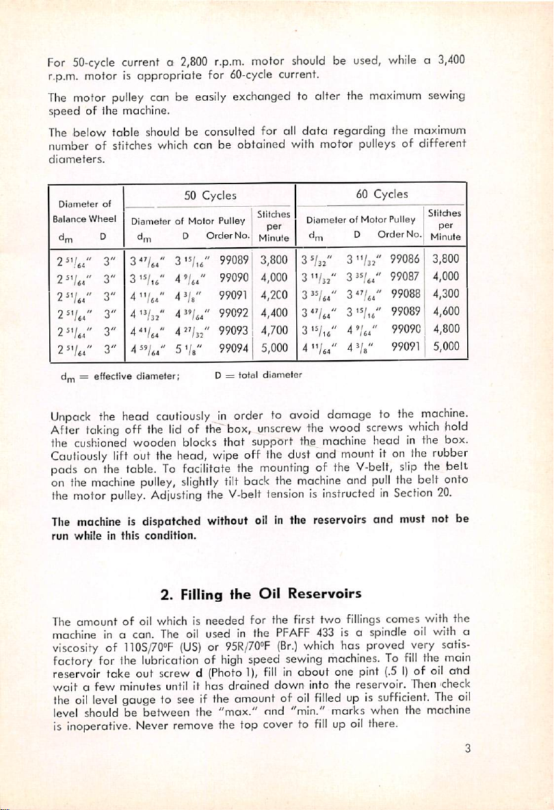
For
50-cycle
currenta2,800
r.p.m. motor is appropriate for
The
motor
pulley
speed
of the machine.
The below
numberofstitches which
diameters.
Balance
Wheel
dm ^
3"
2^'/64"
2^-/64"
2^V64"
2^V^4"
dm=effective
3"
3"
3"
3"
3"
can be easily exchanged to alter the
table
should be consulted for all
DiameterofMotor
dm D Order No.
3
"/u"
4"/44"
4'V3:"
4^V.4"
4"/»"
diameter;
canbeobtained
50 Cycles
'
3
4'/.4'
4^8"
'
4"/84
'
4"/3=
S'/b"
r.p.m.
60-cycle
Pulley
99089
99090
99091
99092
99093
99094
D =
total
motor
shouldbeused,
current.
with
Stitches
per
Minute
3,800
4,000
4,2C0
4,400
4,700
5,000
diameter
whilea3,400
maximum
data
regarding the maximum
motor
pulleysofdifferent
60
Cycles
DiameterofMotor
dm D OrderNo.
3^/s2"
31-/3/'
3"/84"
3"/84"
3'V.6"
4"/m"
3-/32
3"/84
3^V84
3
4'/64'
4^/8-
-/,8
'
'
'
'
Pulley
99086
99087
99088
99089
99090
99091
sewing
Stitches
per
Minute
3,800
4,000
4,300
4,600
4,800
5,000
Unpack
After
the head
taking
cautiouslyinorder to
off
the
lidofthe
box,
avoid
unscrew
damage to the
the
wood
screws
machine.
which
hold
the cushioned wooden blocks that support the machine head in the box.
Cautiously
pads on the
on the
the
The
run
The amount of oil
machine in o can. The oil used in the
viscosityof110S/70»F
factory for the
reservoir take out screw d (Photo
wait
the
lift out the head,
machine
motor
pulley.
machine
whileinthis
table.Tofacilitate the
pulley,
Adjusting
is dispatched
condition.
2. Filling
which
lubricationofhigh
wipe
off the dust and
mounting
slightly
(US)or95R/70°F
tilt back the
the
V-belt
without
the
oilInthe reservoirs and must not be
machine
tensionisinstructedinSection
Oil
Reservoirs
is needed for the first two
PFAFF
(Br.)
speed
1),
which
sewing
fill
in about one pint
mount
of the
it on the rubber
V-belt,
and
pull
fillings
comes with the
slip
the belt onto
433 is a spindle oil with o
has
proved
machines.Tofill
(.5I)of oil obd
a few minutes until it has drained down into the reservoir. Then
oil
level
gauge to see if the
amountofoil
filled
up is
sufficient.
the belt
very
the
20.
satis
main
-check
The
level should be between the "max." and "min." marks when the machine
is inoperative.
Never
remove
the top cover to
fillupoil
there.
oil
Page 6
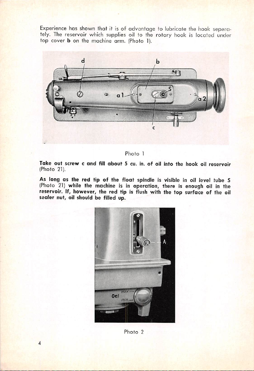
Experience
has
shown
fhof
It is of advantage to
lubricate
the
hook
sepero-
tely. The reservoir which supplies oil to the rotary hook is located under
top
cover b on the machine arm. (Photo 1).
Photo
1
Take
out
(Photo 21).
screwcend
fill
about
5 cu. In.ofoil Into
the
hook
oil
reservoir
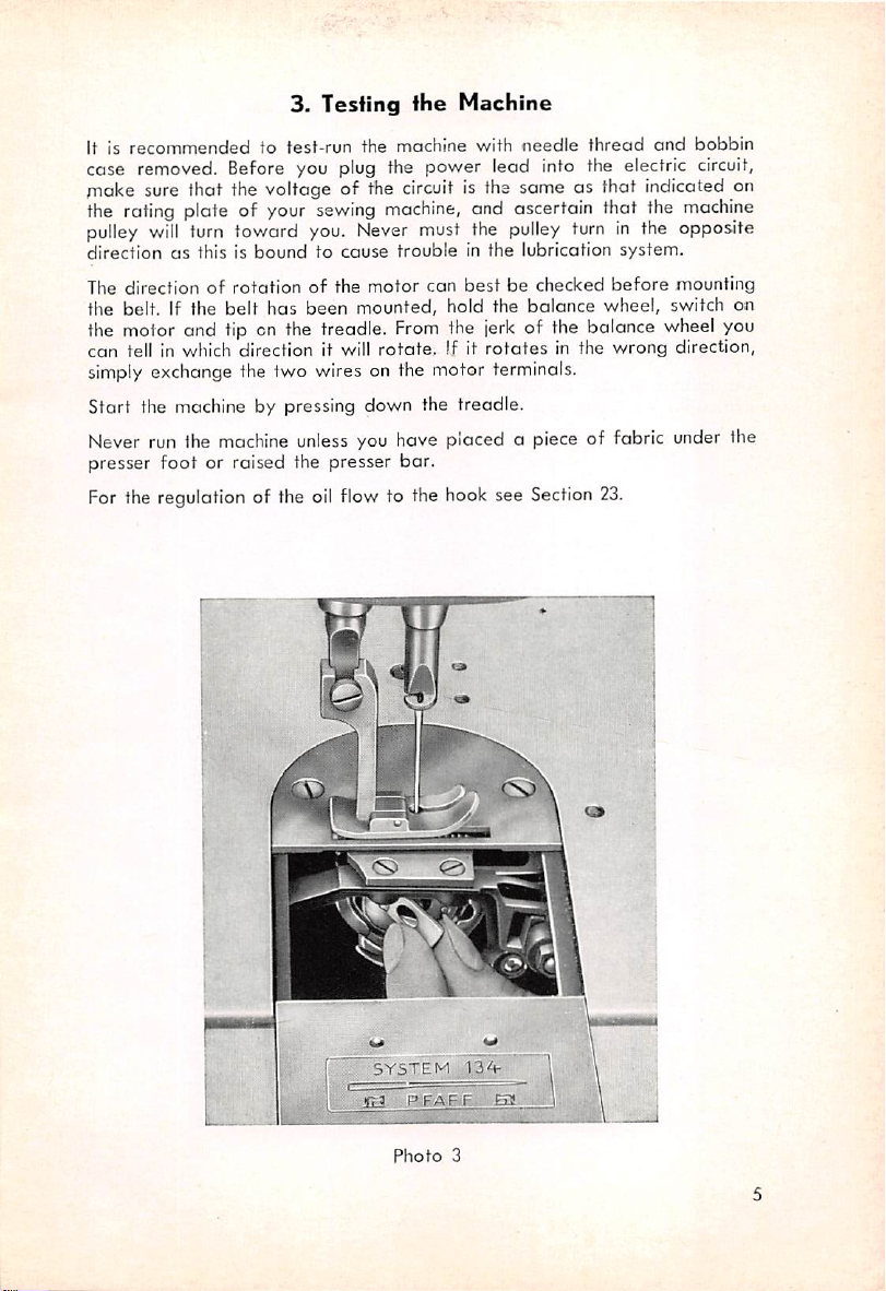
As long as the red tipofthe float spindle is visible In oil level tube S
(Photo
21)
while
the
machineisIn
operation, there Is enough oil in the
reservoir. If, however, the red tip Is flush with the top surface of the oil
sealer nut, oil should be filled up.
mm—V
Photo
2
Page 7
3.
It is
recommended
to
Testing
test-run
the
the
machine
Machine
with
needle
thread
and
bobbin
case removed. Before you plug the power lead into the electric circuit,
niake sure that the voltage of the circuit is the same as that indicated on
the
rating
pulley
will
turn
directionasthis is
The direction of
the belt. If the
toward
rotationofthe
belt
the motor and tip on the treodle.
can
tell In which direction it will
simply
exchange the two wires on the motor terminals.
Start the machine by pressing down the treadle.
plate of your
Never run Ihe
presser
For
the regulation of the
machine
foot
or raised the presser
sewing
you.
boundtocause
has
Never
been
mounted,
unless
you have placed a piece of fabric
oil
flow
machine,
must
troubleinthe
motor
can
From
rotate.
bar.
to the
and ascertain that the
the
pulley
turninthe opposite
lubrication
best
be checked
hold the
balance
wheel,
system.
before
machine
mounting
switch on
the jerk of the balance wheel you
If it
rotates
hook
see
in the
Section
wrong
23.
direction,
under
the
SYSTEM
Photo
3
Page 8
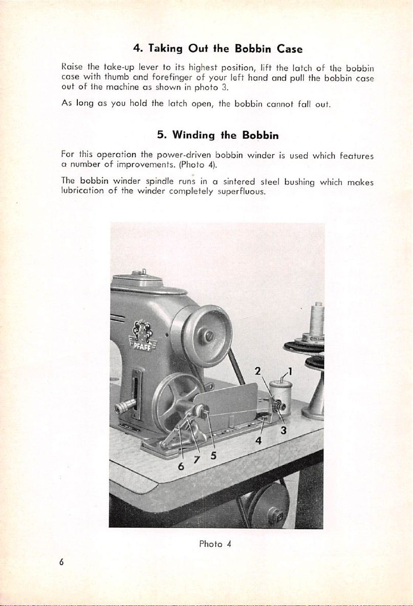
4.
Taking
Raise fhe take-up lever to its highest position, lift the latch of the bobbin
Out
fhe
Bobbin
Case
case with thumb and forefinger of your left hand and pull the bobbin case
out of the machine as shown in photo 3.
As long as you hold the latch open, the bobbin cannot fall out.
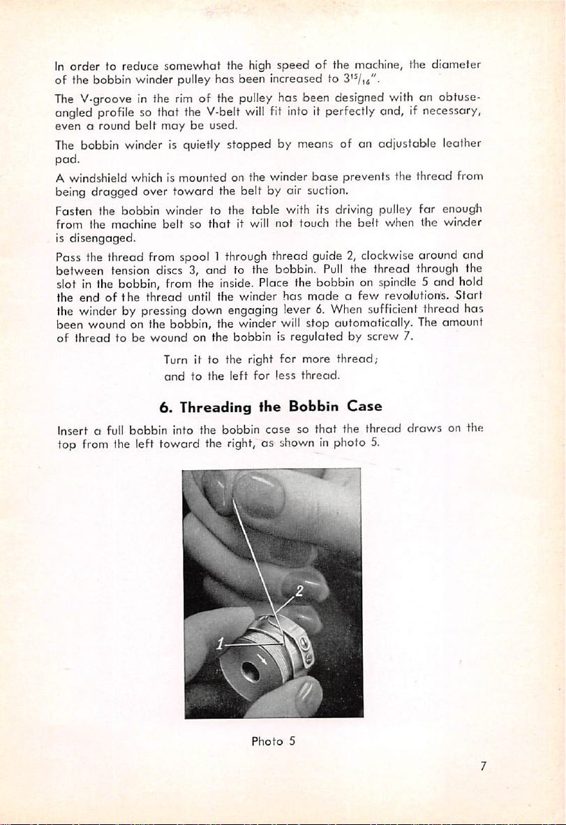
5.
Winding
For this operation the power-driven bobbin winder is used which features
a
numberofimprovements. (Photo 4).
The
bobbin winder
lubrication of the winder completely superfluous.
spindle
runs in a sintered steel
fhe
Bobbin
bushing
which
makes
Photo
4
Page 9
In
order
of the bobbin winder pulley
to reduce
somewhot
the high
has
speed
been Increased to
of the machine, the
diameter
The V-groove in the rim of the pulley has been designed with an obtuse-
angled profile so that the V-belt
even
o round
belt
may
be used.
will
fit into it perfectly and, if necessary,
The bobbin winder is quietly stopped by means of an adjustable leather
pad.
A windshield which is mounted on the winder
being dragged over
toward
the belt by air suction.
base
prevents the
thread
from
Fasten the bobbin winder to the table with Its driving pulley far enough
from
the
is
disengaged.
machine
beltsothat
it will
not
touch
the
belt
when
the
winder
Pass the thread from spool 1 through thread guide 2, clockwise around and
between tension discs 3, and to the bobbin.
Pull
the thread through the
slot in the bobbin, from the inside. Place the bobbin on spindle 5 and hold
the
endofthe
the winder by pressing down engaging lever 6.
thread
until
the
winder
has
madeafew
When
revoilutions.
sufficient thread has
Start
been wound on the bobbin, the winder will stop automatically. The amount
of
thread
to be
wound
Insert a full bobbin into the bobbin
top from
1he
left toward the
on the
bobbinisregulatedbyscrew
Turn it to the right
endtothe
6.
Threading
left
right,
for
more
thread;
for
less
thread.
ihe
Bobbin
casesothat
Case
the
as shown in photo 5.
thread
7.
draws
on the
Photo
5
Page 10
Pull
the thread into slot 1 end draw it under the
eye2.Place
the
bobbin
case
with
the
bobbin
tension
on
the
spring into delivery
center
studinthe
bobbin case base and moke sure that the end of the latch points toward
you. Press the bobbin case all the wayinuntilitclicks
This
is very important as, otherwise, needle or bobbin case breakage may
result.
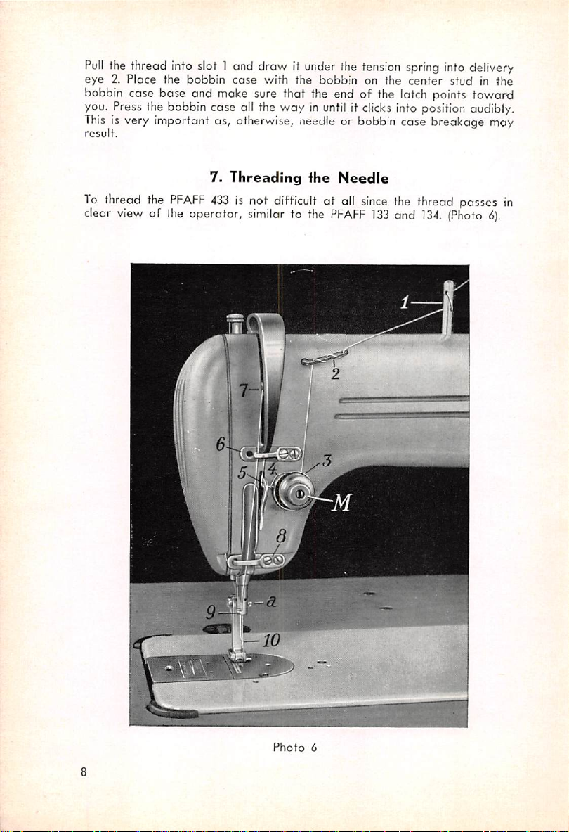
7.
To
thread the
clear
view
of the operator,
PFAFF
Threading
433
is not
similar
difficult
to the
the
Needle
at all
PFAFF
info
position audibly.
since
the thread passes in
133
and
134.
(Photo
6).
Photo
6
Page 11
Pass
the
thread
from the
thread
unwinder to
thread
guide pin 1
and
through
both holes in order to keep the thread from whippingathigh speed.Bythe
same token, pass it through all three holes in thread retainer 2 as shown
in photo 6, then between tension discs 3, through thread check spring 4,
under thread regulator 5, through guide 6, up and from right to left through
eyelet 7 in the take-up lever, down and through thread guides 8 and 9, and
from left to right through need'le eye 10.
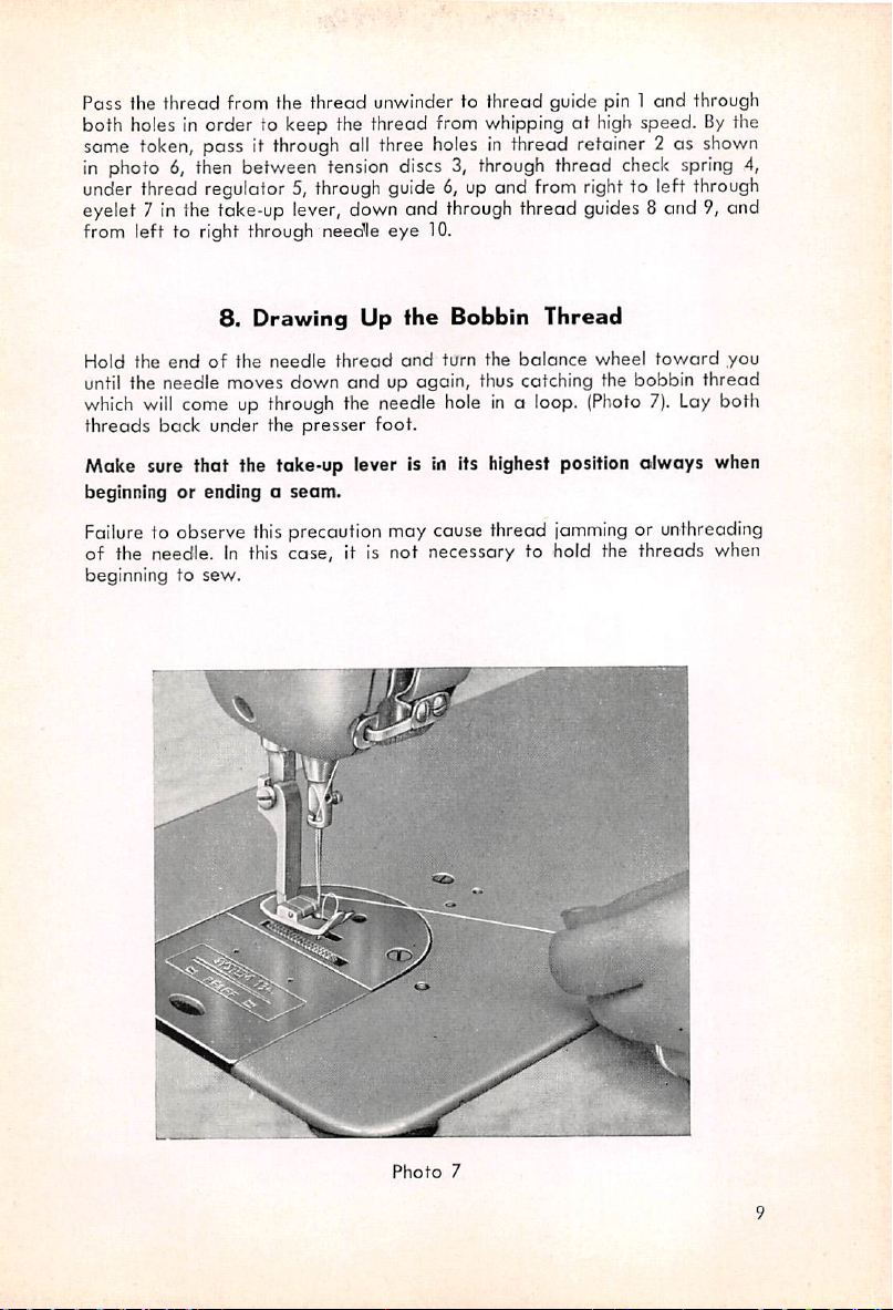
8.
Drawing
Up
fhe
Bobbin
Thread
Hold the
endofthe
needle
thread
and
turn the
balance
wheel
toward
you
until the needle moves down and up again, thus catching the bobbin thread
which
will
threads
come up through the needle holeina loop. (Photo 7). Lay both
back under the
presser
foot.
Moke sure that fhe take-up lever is in Its highest position olwoys when
beginningorendingaseam.
Failure to observe this precaution may cause thread
of the needle. In this
beginning to
sew.
case,
it is
not
necessary
jamming
to hold the
or unthreading
threads
when
4^
Photo
7
Page 12
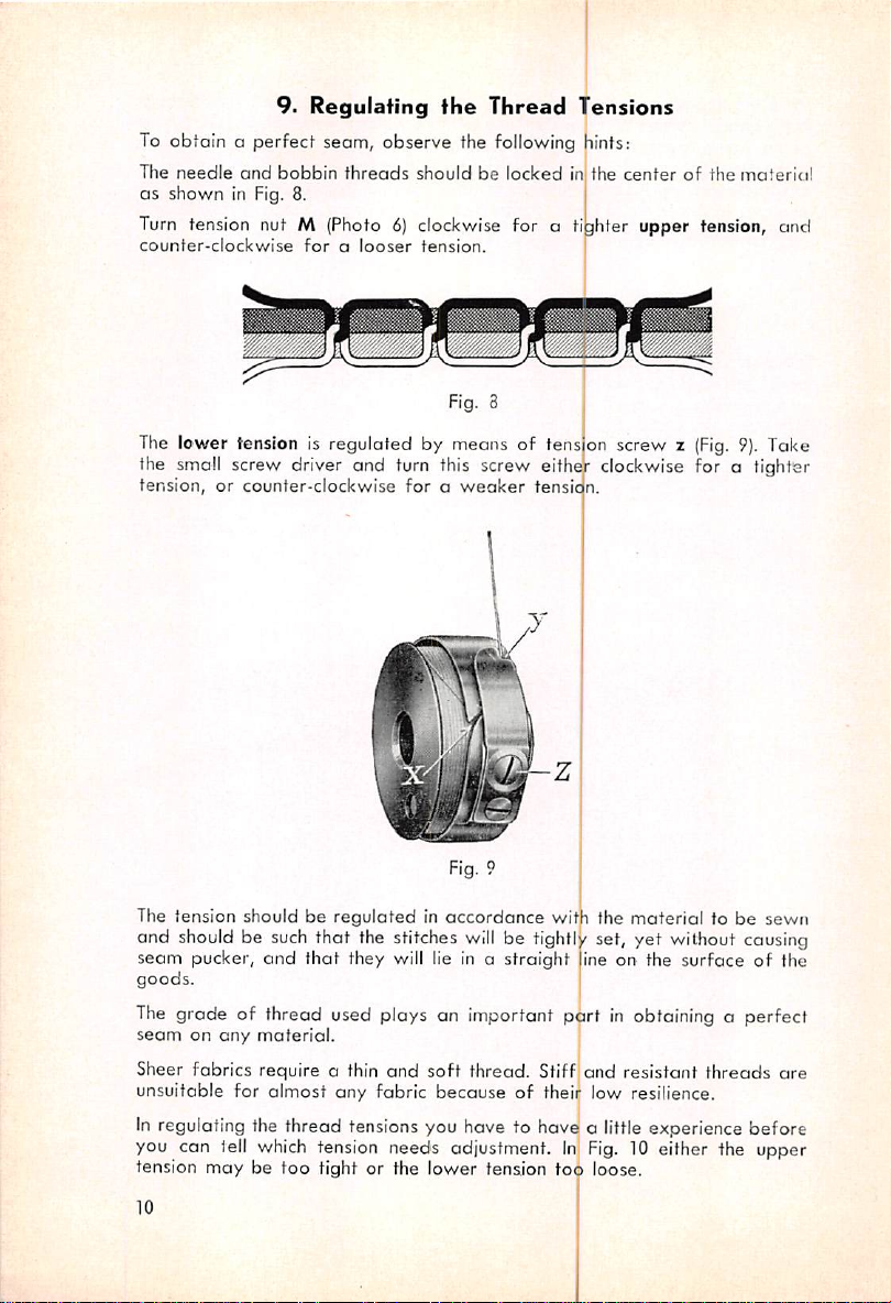
9. Regulating the Thread Tensions
To
obtain o perfect seam, observe the
The
needle
and
as
shown
bobbin
in Fig. 8.
Turn tension nut M (Photo6}clockwise for a
counter-clockwise
threads
foralooser
shouldbelockedinthe
tension.
following
hints:
tijhter
centerofthe
material
upper tension, and
The lower tension is
the
small
tension,orcounter-clockwise
The tension should be
screw
and should be such that the stitches
seam pucker,
goods.
The grade of thread used plays an important
seamonany
Sheer fabrics require a thin
unsuitable for
In
regulating the thread tensions you have to have a little experience before
you can lell
tension
material.
which
maybetoo
regulated
driver
and
turn
foraweaker
regulatedinaccordance
and
that
they will lie in a straight ine on the surface of the
and
almost
any
tension
fabric
neecis
tight or the lower tension
by means of tens
this
screw
will
be tightly set, yet without causing
soft
thread. Stiff and resistant
becauseoftheir low resilience.
adjustment.
on
eithe
tensia
screw
' clockwise for a
n.
with the
part
in obtaining a perfect
In
Fig. 10
too
loose.
material
either
z (Fig. 9).
to be
threads
the
Take
tighter
sewn
are
upper
10
Page 13
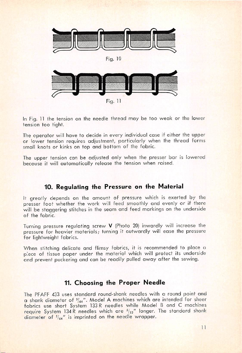
In
Fig.11Ihe
tension
too
tension
tight.
Fig. 10
Fig. 11
on the needle thread may be too weak or the lower
The operator
will
have to decide in every individual case if either the upper
or lower tension requires adjustment, porticularly when the thread fornts
small knots or kinks on top
The upper tension can be adjusted only when the presser
because
it will
automatically
10. Regulating
it greatly depends on the amount of pressure
presser foot whether the work
will
be staggering stitches in the seam and feed markings on ihe underside
of
the
fabric.
Turning
pressure for heavier materials;
for lightweight fabrics.
When stitching delicate and
piece of tissue paper under the material
and prevent puckering and can be readily pulled
The PFAFF 433
o
fabrics use short System 133 R needles while Model B and C machines
require
diameter
pressure regulating screw V
11.
uses
shank
diameter
System
of is imprinted on the needle
standard
of
134
R needles
and
release
the
flimsy
Choosing
round-shank
ModelAmachines
bottom
of the fabric.
bar
the tension
Pressure
will
feed smoothly and evenly or if there
(Photo
turning
it outwardly
when
raised.
on the Material
which
is exerted by the
20)
inwardly
will
will
ease the pressure
fabrics, it is recommended to place a
which
will
protect its underside
away
after
the sewing.
the
which
Proper
are
needles
which
longer.
wrapper.
Needle
witharound
are
intended
The
standard
is lowered
increase tlie
point
atid
for
sheer
shank
11
Page 14

The
needleisof
fore
should be
eminent
choseninproper
used.
For
lightweight
ugly
needle
When
using a thin
and,
conversely, when using thin
stitches
Select
may
the
fabrics, a
holes in the fabric.
needle
occurasa
correct
needle
importance
thin
needle
with a thick
result.
from
the
for
obtainingaperfect
relation
to the
thread
and
seam
fabric
and
j
shouldbeemjployedinorder to avoid
thread,
thread
chart
in a
below:
the
thread
is likelytobreak
thick needle, skipping
there
weights
of
Needle
Needle
Size
70
75
80
85
90
We
warn
wrapper
plus
the
Never use rusty
Cotton
Silk
Cotton
Silk
Cotton
Silk
you
should
needle
Thread
against
bear
system.
needles!
Weight
using needles of unknown
the inscription "Needles for
Only the exceptional quality of the needle
sewing
PFAFF
the thread.
to
and
prevent
thread
433, o needle with a rough surface will quickly
This
heat
and fuses easily. |
is particularly true of nylon thread which is highly sensitive
If the ordinary needle should get
100-80
100 (0)
80-60
80
(B)
60-40
70 (C)
and
Thread
Needle
Size
100
110
120
breaking.
Due
Ch
Cot'ton
Silk
Line n
Cotton
Silk
Linen
Col
Silk
Linen
finisl^
to
arf
Thread
ton
origin
Pfaff
will
Weight
even
Sewing
ensure trouble-free
get
too
hot when stitching dense and resistant
40-30
60 (D)
90-80
30
50(E)
80-50
30
40
60-40
if the
needle
Machines"
hot and scorch
materials or long panels of fabric, it is recommended to exchange it for
o superfinished, chromium-coated System 133 or
[134
needle which may be
procured from us. |
If even o superfinished needle should get too hot, the
fitted with a "Schmetz needle cooling device".
ideally suited to solve the problem since it requires no
machine
and
does
not disturb the
operator.
The
draft
PFAFF
This
efficient device is
attachments
of air which is
433 may be
to the
caused
by the needle motion is not noticeableatall. When fitted with this device,
the machine
will
stitch also resistant fabrics with appreciable speed.
12
Page 15

1. Raise the
2. Take the small
3.
Pull
out
needle
the
needle.
12.
Changing
bar
to its highest position.
screw
driver
and
fhe
loosen
Needle
needle
set
screw
I
a (Photo
•6).
Photo
12
13
Page 16

4.
InserfaSystem
and
push it upasfar
faces
to the right.
5. Tighten needle
The
PFAFF
which
canbeset
(Photo
2).
Once set, a special device will lock the, length of stitch so
133
Ror
134Rneedle
as it will
set
screw
a securely.
13.
Regulating
433 is fitted with a job-proven, spring-loaded stitch regulator
for the length of stitch
the
go.
into
the
Make
Length
desired
ojiening
sure
df
of the
the
needle
short
that
Stitch
,by turning thumb nut A
bar
groove
that
it cannot inadvertently be changed while sewing. 1|he numbers on the scale
indicate
up
Switching the machine to
by
the stitch length in millimeters. By pushing
as
farasit will
foot
control. When letting goofthe stitch
go,
the machine can be
reverse
stitching can be
the
set
tar
regulator
stitch
feeding
done
regulator
reverse.
either by
lever it will
lever
hand
auto
matically return to its initial position.Inorder to relieve the right leg which
or
/
Photo
13
14
Page 17

actuates
arranged
both
The
moniously
The presser
or by actuating the knee lifter with the right knee. The knee lifter
be
loosen screw b and
screw c (Photo 13). To permit the machine to be tilted back, pull out pin d,
which
(Photo 18),
The
tion rotary hook.
one is
The hubofthe
and ensures an absolutely vibrationless
the
knee
on the left. The foot-controlled reverse
hands
free to
PFAFF
connected
adjusted
can
end
PFAFF
433 is organized with the trade-tested
lifter, the
manipulate
433 is equipped with a knee lifter mechanism which is har
with the
foot
is lifted either by raising the presser
horizontallyaswell as vertically. For horizontal adjustmenf,
be easily
adjustatscrew O; for vertical adjustment, loosen
strip the knee lifter
The
that
the
PFAFF
hook
carriesanoil
treadle
the
work.
14.
The
headofthe machine.
reached
through an opening in the dress
15.
The
only difference between previous models and this
433 hook is provided with centrifugal lubrication.
for
actuating
Knee
Lifter
shaft
with the knee lifter lever.
Hook
feed
PFAFF
retainer
which is
running
of the hook.
the stitch
regulator
mechanism leaves
bar
lifter by hand
134double-revolu
meticulously
Emerging
pad
can
guard
balanced
from
o jet in the hook shaft bushing the oil is atomized by centrifugal force and,
through a second borehole, enters the hook race where it effects a depend
able
and
permanent
lubrication.
After removing the needle plate, the amount of oil, which is set for
ordinary sewing requirementsatthe factory, can be regulated as instructed
in Section 23. If this adjustment should become necessary, it should be
performed
only by a mechanic.
is
16.
The
All varieties of the
PFAFF
Bobbin
433
are
Case
fitted with a positive mechanical opener.
Opener
Since the advantages of this mechanism are not generally known, a few
explanations will be given here.
The interlocking of the needle and bobbin threads
which
is necessary to
form a lockstitch seam is accomplished in two different ways, depending
In
on the class of machine.
are
locked
thread loop
by passing the shuttle with the bobbin thread
which
is formed as the needle rises after
long or vibrating shuttle machines the threads
through
having
the needle
passed the
lowest point of its stroke. Another method consists in passing the needle
thread loop around the bobbin
position.
case
while the latter is in a stationary
16
Page 18

In machines with oscillaUng
shuttle mochines, the loop forming
the needle
a
centeroroff-center
With the double-revolution horizontal rotary hook, the type of loop
which is generally used in high
PFAFF
case at every other revolution of the
In
rotary
hoving
in
ordertomakeanopening
The
the
against
result,
passing between position finger and edge of slot and may break. The
only
The
in
most cases, has to be eased to an extent
setting of stitches impossible when the machine is operated at o reduced
speed.Toeliminate
are organized with a mechanical bobbin case opener whose finger,
is
carriedonthe
the bobbin case at the right time and contrary to the direction of rotation
of the
the
position
high
First of all, as the needle thread is not subjected to additional or fluctuant
strain,
speed. For this reason, the thread tensions may .be so set os to ensure
an even setting of stitches and prevent
speed and alsoinsheer
breaking has been greatly eliminated, it is possible to use threads of
low
will
sew
hook
All
of the above
case opener have lead to its incorporation not
in the heavy styles of the
Timing
as
instructed
thread
loop around the bobbin
433,
the
needle
hook machines which have no mechanical opener, the needle thread,
passed
friction
sewing
the
remedytothis
drawback of this remedy lies in the fact that the needle thread
around
between
speed.Bythe
the
position
needle
hook
thread
conditionisto
these
opener
sewing
speed
tensile
are
the
flimsy
not
of the
hook.Inthis
finger
sewers
upper
and the
are
tension
strength
even
fabrics at top speed
completely
advantages
mechanical
in
Section
loop
takers,
suchascentral
part,
in moving back and forth,
cose
position.
speed
thread
loop
the
bobbin
through
race
and
same
slot
token,
inc/"easasasthe
hastoovercomeastronger
disadvantages,
shaft,
case the
position
manifold.
need
not be
fabrics.
for
high
smooth
which are inherent in the mechanical bobbin
PFAFF
opener
29.
sewing machines
is passed
case,
arourid
hook.
hastoturnl
whichitcan
bobbin
case
the
pressureofthe
sewing
ease
the
threap
PFAFF
assumes
the
needle
thread can pass
slot.
The
advantages of
changed,
puckering
Secondly,
speed operations.
even
sincd
when
yet.
433.
should
be performed
bobbinorbeak
which is carried either In
passes
|
end
the stationary
'
the
bobbin
fiass.
trjcreasesinproportion
position
speed
goes
resistance
tension.
which
will
make the proper
higji
speed
sewing
functionofslightly
freely
this
regardless
of the material at
the danger of thread
the bearing surfaces of the
|
onlyinthe
|
Thirdly,
only
of the
light
by o
taker
also in tlie
bobbin
case
slightly
finger
up.Asa
when
tension,
machines
which
rotating
between
device
tsewing
the
machine
but also
mechanic
for
aniy
io
ci
To
facilitate the
dog,
strip
16
the
17. Tilting
removal
knee
lifter
the
of packed
and
tilt the machine
Machine
lint
between
bad
Back
sewing
hook
and feed
Page 19

To do this, reach through the hole in the middle of the dress
the table
and
pull out pin d (Photo
18).
Now pull the knee lifter with its
guard
under
shaft forward out of its bearings. This done, tilt the machine back and resi
it on the
light
Skilled
with the take-up lever in its highest position or to lay the threads
wooden
bracket.
machine
18.
rest
pin or on the
Dismantling
the
base
Hook
of the
operators who make it a routine olways to begin or
swung-away
Finishasean>
sew-
(boick
under the presser foot when commencing to sew will hardly ever encounter
thread
jamming in the hook race.
If thread should happen to jam in the hook race, try to get a hold of the
end of the thread tind to pull it out while turning the balance wheel back
and forth slightly. If this action fails to free the jammed thread, dismantle
the
hook
os
instructed
below:
Photo
14
17
Page 20

1. Tilt the machine bockasdescribed
2. Raise needle
still
be turned. If not, remove position
3. Loosen
the
parts,
be found since the
4. Pull
out
thumb
bar
and
take-up lever, provided the balance wheel con
set
screw c and pull
the correct position of the finger
shaftismarked
the
and
bobbin
forefinger.
case
with
off
the
opener
bobbin,
in Section l7.
finger
finger b. When reassembling
with a grc
5. Return the machine to its upright position o
and
feed
dog.
6. Take
sure
out
that
screws
youdonot
e,,
and
ej (Photo 15)
confuseitwith
and
thread
Bracket a first.
on
the
ove.
se
zing it by the latch witfi
nd
remove
shaft
{Photo
can
needle
remove hook gib d. Be
3ull-off
flange
f.
14).
easily
plate
7. Turn the
opposite
is
case
components
base
flange.
18
Photo
15
balance
base
wheel until the first
slot
i in the
can
be
taken
in the
same
bobbin
out
position.
of
screw
f, in
case.
When ih this position, the
the
hook.
Note
Photo
that
thread
tip 1ofthe
puil-off flange f
17
shows
bobbin
bobbin
the
hook
case
should be positioned between hook point g and tip f of the
Page 21

8. Seize Ihe bobbin cose
left
end
down,
and
9. Clean hook and bobbin
pointed wooden instrument, never with o screw driver.
10. It is recommended to screw on position finger bracket a before replac
ing
Ihe
sure that
bobbin
is a clearance of
the
bottom
11. Reploce hook gib d and tighten screws e,,Ojand
12.
Push
the opener finger onto its shaft. Take care that screw c
in the
lengthwise
case base.
position
of
slot
aboutVjof the projection on the
screw
c securely. (Photo 14).
base
take
finger
about
I.
with thumb
iit
outofthe machine.
case
base
When
inserting
h engagesinslot Iinits
between the tip of position finger h and
and
thoroughly
the
forefinger, pull it to the
and
remove lint with a
bobbin
case base, make
rim
and that there
e^.
ride:s
groove of the shaft and that the opener finger covers
rim
of the
bobbin
cose base.
Tighten
Photo
16
19.
Care
Since
the
PFAFF
433
any
maintenance
check the automatic lubrication system regularly and clean the machine
thoroughly.
be replenished.
It is
fluff which have accumulated between needle plate and feed dog and on
From
urgently
is provided with automatic lubrication there
be
required
timetotime
recommendedtomake
and
while
the
Maintenance
the
machineisin
oilinthe
it a
daily
hook
lubrication
routinetobrush
operation.
system
off
will
hardly
Merely
should
lint
and
19
Page 22

the hook when the machine is In
high percentage of dressing which has an abrasive effect on the sewing
mechanism, in time excessive
including
r"
the
bottom,
shouldbecleaned
permanent
wear
would develcp. The whole machine,
use. As the fluff contains a
withasotit
rag.
Oi
62
(?3
a
a
Photo
17
Great emphasis has been placed on making the oil rdservoirs in the
as leak-proof as possible.
knows that the capillary attraction of the oil cannot be completely over
come with machines which contain large quantises of oil—and sewing
machines are no exception. Capillary ottroction denotes the property of
thin-bodied oil to spread in every direction and seap even through the
tightest packings, covering the
oil
film.
The
greatly
of the
that a minor leakage may occur when the maihine has been idle for
several
important
result in insufficient lubrication once the temperature has dropped to nor
mal.
This
functional
contributedtoeliminating
oil.
But
even
days
or the
that
youdonot
temporary
preventedbywiping
outside of the machine and, particularly, the needle and presser
the
underside
There are many people who prefer, for sewing machines, a clear, colorless
oil in
ordertoavoid
should
particles as any other brand and that its
result
of optical refraction
yellow,
The
flow of oil to all lubricating points
mechanic.
of
the
like
to point out that yellowish oil is as pure and free of color
greenorblue.
But
everybody who is familiar with the problem
outer
surface of the machine with a thin
arrangementofvent
excess
rises
the
flowofoil
pressure
given
above
rag,
yellowish
should
so, for the
temperature
reasons
throttle
nuisance
head.
can best be remedied and
off,
withaclean
yellowish spots on the work. In this connection we
which
makes olso the cut edges of glass appear
I
PFAFF
holetonthe
l^nd
abdve,
normal. In this case it is
PFAFF
attendant
the
possibility
433
expansion
Idrasticallyasthis
soiling
the
|oil
film
color is
of the work
that
covers
nothing
bars
|
^be
regulated only by a
has
exists
might-
the
and
but the
433
20
Page 23

Insfrucfions
20.
The
for
V-Belt
Mechanics
Drive
When mounting the V-belf for the first time, remember
mounted
pulley.
The
motors
motor
or a nut, can be
the belt. (See PKA
It
avoid excessive pressure on the
heoting
belt
will
wear
more
various
which
motors
meet
which
German
bracketbymeansofa hinge
readily
motor
takes
some experience to
and
seizingofthe machine.
quickly. Hence,donot
are
used
DIN 42691
to
requirements.
stud
swung to
any
desired
picturedinphoto
set
the tension on the belt correctly so as to
top
shaft
drive
and,
18).
bearings
the
PFAFF
They
after
loosening a
position in
force
and
that
a crookedly
the
beltonthe
433
are
are
hingedonthe
order
attendant
standard
set
screv/
to tension
over-
Photo
18
The belt is correctly tenstoned if you con readily compress it
ofoninch
midway
between
the
pulleys.
cuboui
^'4
21
Page 24

Securely lighlen either the hinge siud nut or
so
thot
it will
not
get
loose while sewing. r
sat
sc'ew
k (on
PKA
motors)
If you foil to tighten this screw securely, the motor will be held only by
the
V-belt
in turn, will
The flow of oil to the sewing hook, the
parts
the machine
oil flow to specific
in to
balesoffabric, a
Sudden
o
temporary
Arm
Through a hole in this tube a jet of oil squirts up
reverberates
leadtooverhaating
con be regulated
leaves
do
the
job.
changes,
adjustment
end head parts are
and
and exert c
one-sided
21.
Regulafing
separately
the
factory.
operating
When
used
more
liberal supply of oil is reqi.
particularly
of
pressure on the tdp shaft bearings
and
andisset
If it should
requirements,
for
permanent
abrupt
the
oil
supplied
sprays
the
bevel
seizingofthe machine.
the
Flow of
top
shaft
Oil
bearings
for normal requirements when
rises, in
flow.
with
gears,
become
oilbymei^j
connect
necessarytoadapt
a me
rhanic
oper
ationinseaming
red
temp
erature
ns of line 1 (Photo 19).
against
ng
than
rods
and
has
tobecalled
for
may
the
and
which,
the heacl
the
whole
short
runs,
necessitate
top
cover,
eccentrics.
197
Photo
19
maintaining a
constant
filmofoil
between
all
parts
in moving
Of the two valves in line 1, one regulates the flow of oil to the
and
the
top
shaft
front
and
oil supply for the
22
top
shaft
center bearings wh"
rear
bearing.
e
the
other
contocf.
head
controls
parts
the
Page 25

When slots n and o (Photo 19) point lengthwise of the arm, the valves
open.
By turning them
or shut
valvenopen
both
top
off
shaft
22.
completely. It is
and
Regulating
thus to
bearings.
either
the
woy,
recommended,
ensure
proper
Flow of
the oil flow
lubricationofthe
Oil
canberegulatedasdesired
however,
to
the
normally to
head
Head
Parts
parts
are
leave
ond
As may be seen from
photo
20, the hollow top
shaft
end with regulating stud o which is held in position by
stud serves to regulate the
hollow
top
shaft
to the
amount
take-up
turning it clockwise. When the + symbol is
needle
Whei'i turning the
opposite
bar
crank,anunrestricted
stud
either
the red mark, the flow of oil is restricted accordingly. (Fig. 20a).
of oil which is pressure-fed from .the
crank.Toadjust,
loosen
opposite
oil flow
to the right
passes
or
to the fake-up crank.
left until the — symbol is
is closedatits one
set
screw p. This
set
screw
p by
the red mark on the
Photo
Fig.
20
20a
23
Page 26

There is no hard
OS
to ensure
amount
Hold a piece of
the machine
that
of oil, however, can be easily established by the following tes't:
cardboard
and
may be required to
which
should
be
the
To
ensure
adequate
heavy strain, an
wound
bushing,
Ground
wound
the
around
and
fosf rule for properly regulofing the flow of oil so
the
head
ports
will be
between the presser
run the machineattop
obtain
case
after
two
10
lubricationofthe
oil
wick
has been passed
needle
the
bar
needle
upper
adequately
thin lines of
speed.
seconds.
needle
bushing,
bar
and
secured
lubricated. The correct
bar
and
Turn regulating stud o
spray
bar
|/hichisconstantly
throudh
ta|<en
the rear wall
oil on the
the take-up
downtothe
by a clip. (Photo 20).
cardboard
under
link
stud,
lower
of
as
second
A
is
secured
fakeup
The
feed
This
the
and
delicate
Becauseofthe fine grit which mixes with the lubri
feed
it
does
for
For instructions about
Section
Oil is
tubes2and
which is
stops,
oil wick connects the
inside
the
link
rotary
lubrication
feature
sewing
clean
oilofexcellent
fabrics.
lubrication
not
the
lubrication
wheneveritbrushes
23.
hook
has
hookasthe
impair its lubricity in the
machine
Regulafing
of
the PFAFF 433 is oiled
systemofthe machine.
proved
system
of
the
filling
2. i
conducted
generatedinpumppand
the
to the
3. When the machine runs,
valveisclosedbyspring
take-up
head
past.
fhe
very
advantageous
most
sensitive
lubricity. This is
will
soon
assume
hook.
the hook
rotary
hook by
conveyed
link
withascrew
Hook
part
least,
action.
stud
Lubrication
indepedentlyofthe
becauseitpermitstosupply
in a sewing machine with
particularly
a dark
migh
oil
reservbir in the top cover see
means
valve
v is
through
(Photo
w
th a small oil
and
delivers
importantinhandling
:ant,
the
er
soil
of the
opened
22).
oil in
color
which,
the
thread
transparent
by oil
tube
1. As the machine
pad
which
oiltothe
forced
fresh,
the
forced
although
if
used
plastic
pressure
Tube 3
conducts
bearing
photo
ing the needle
for
24
less
which
23, this
oil.
the oil from
regulates
screw
canbereached
plate.
Turn the
the
valve
v to regulating
oil
flow
screw
to
the
withasmall
to the left for
sewing
screw
screw
more
q in the hook
hook.
As
driver
after
oil
and
to the right
shown
remov
shaft
in
Page 27

Phofo
Photo
21
22
25
Page 28

Tube 5
plies
which
oil
onlytothis
connects the oil pump with hook shdft front bearing G
bearing.
Photo
23
sup>
Having
retainer,
hole
The oil flow must be
correct
as
Placeapiece
ten
inch
ticles which
After
regulating screw q in case the oil marks should foil to appear.
The amount of oil which is to be fed to the sewing hook greatly depervds
on
Since
dressed materials require a lavishoil flow to the
tends not only to choke the oil conduits but also to
andto"blacken"
All this con be avoided by permitting the oil to flow more profusely. This
will
and,
26
passed
and
amount
follows:
seconds,
apart,
sewing
the
material
the
keep
instead,
regulating screw q, the oil drips
is flung
away
of
oil
by centrifugal
adapted
required
enters the annular groove in the hook.
of stiff paper over the
check
are perceptible on the paper. These lines are
are
flung
for
about
tobesewn.
particlesofthe
the
the dressing particles from absorbing enough oil to settle down
will
wash
whether
two
away
from the roce and Ihe front
fifteen minutes,
dressing
sewing
them
thread.
away
force,
to specific operating requirements. The
under
ordinary
needle
thin
linesofSfiray
repeat
mix
with
outofthe
drains
ope
plate
the
the
hook.
i
ito
the
down
rating
jopening
oil,
above
i)il
and
dewing
wear
|
grooveofthe
throughanoblique
conditionsisfound
and, after about
about of on
made
edge
check
thicken
hook.
the hook unduly
oil
by oil
and
it,
par
slacken
heavily
mixture
of the hook.
This
Page 29

The
operator
correctly
heavily
bath
towels)
will not encounter any difficulties in regulating the oil flow
when
dressed
materials
and
she
that
for sewing flimsy ond
all
undressed.
remembers
that
or for long runsathigh
the
normal
delicate
oil
flow,oreven
materials
more
which,
oil is
required
speed
a little
(bed
less,
withoutanexception,
for stitching
sheets
will
or
suffice
ore
For short runs
fhe oil
flow
and
speeds
to the hook
below
may
4,000 s.p.m. in the
be shut
off
completelyinfavorofmanual
garment
manufacture,
oiling.
If
the
hook
should
either
cannot
touch it with your
there
other
is an
On the
that
soilingofthe
hand,
excessive
material
if oil
may
blacken
hand,
spots
flowofoil
the
thread,
or
this is a sure indication of
appear
on the
passing
to the
result.
becomesohot
inadequate
bobbin
case
sewing
this
hook
that
you
oiling.
indicates
and
that
These signs greatly help in keeping the oil flow to the hook at the correct
level ond in
adapting
it to specific
24.
Changing
operating
the
requirements.
Oil
As with any other high speed sewing machine with automatic lubrication,
regular changing of the oil will do much to increase the service life
of
the
machine. Particularly during the break-in period, the oil should be changed
This
more frequently.
particularly while a new machine is being broken
Of
the oil
in
ordertocorrect
does
To comply with the
First change
Second change
Third change
and
is necessary in order to remove the grit which occurs
in.
not
affect
this
above
thereafter
its lubricity, it is not
condition.
necessarytochange
requirement, follow the schedule given below.-
after
one week's operation
after
four week's
after
three months' operation
every
three
months
As the overheating
operation
the pil
Of
course, this schedule applies only to the
The oil which is used up in the
replenishedatshorter
To
drain
the
oil
while the machine is idle.
in
the
reservoir.
from
intervals.
the
bed
Take
separate
oil
reservoir,
care
thatnoused
automatic
lubrication system.
hook lubrication system has to be
take
out
the
large
drain
oil, mud or
grit
screw
remains
The drained oil may be reused for other lubricating purposes after it has
been
filtered through several lays of linen.
New
oil is filled inasinstructedinSection
2.
27
Page 30

25.
Regulating
The check spring assists the take-up lever in takirig up the balance of the
needle
in setting the stitch to the desired tightness ond in controlling the slack of
the
the
thread
needle
thread
after
the loop has
thread
from the spool until the needle
from
the
passed
the time the
Check
around
descending
reaches
Spring
the bobbin,
t|ake-up
the
Action
and
lever has drawn
goods.
further
Photo
24
The check spring is checked in its downward motion by a stop on its bushing
which
canbeadjusted
insertoscrew
driver
Since thread regulator R (Photo
bracket,
passes
amount
material
not
Vertical
ing
turning the check spring bushing. For
coordinate
it moves up
over
irregularities in thickness. With this motion it regulates the
of
thread
and
havetotakeupexcess
screw
complements the action of the check spring so that it
adjustment
u (Photo 20). It
both
the correct balance of the thread but also
cularly.
28
as required. To do this, loosen
into
the
slotoftension
20)
and
down with the presser
which
varies
slack
of the
thread
has
adjustmentssothat
is mounted on the presser
with the inequalities in thickness
thread.
regulator is
the
same
the
effect
best
check
set
studtand
made
on
results, it is
spjring
draw
screw
turn
barasthe sewing
possible
the
thread
recommended
will
not
up the thread perpendi
s (Photo 24),
the
stud.
bar
of
after
loosen
control
only
take
lifting
foot
the
does
as
to
up
Page 31

Once
you
are
familiar with the functionsofboth
thread
right
The check spring is correctly
of
of
regulator,
away,
without
the
thread
travelofthe
you will be in a position to
first having to try
set
when
take-up
the
needle
lever is
if it
stitches
somewhat
out
has
into
completed
is normal, it may be necessary to allow the
of
play
at
the time the
thanisusualsothat
needle
reaches
26.
SelHng
fhe
it will
the
Needle
exert
goods.
BaratCorrect
the check spring
perform
different
proper
settings.
taking up the
the
material.
lorger
check
still a slight pull on
Since
with the PFAFF 433
spring a larger amount
Height
and
the
adjustmetit
balance
the
amount,
than
the
thread
To facilitate setting the needle
about
bar
be flush with the
of
this
form the loop. In
wide
has
been
has reached the lowest point of its stroke, the
bottom
mark
coincides
with
other
baratthe correct height, a small depression
milled into
edge
the
words,
the
of the lower needle
amountofneedle
when the
bar.
needle
(Photo
top
bar
rise which is
bar
25).
When
the
needle
of this mark should
bushing. The widtti
risen
required
about
has
to
^1^"
Photo
25
29
Page 32

from the lowest point of its stroke, the point of tf
site
the
center
line
of
the
needle
eye.
enter Ihe loop
This is the position in which the
needle
afterithas
been
and
about
.04''
point
sufficiently enlarc
5
hook
above
Df
ed.
the
shouldbeoppo-
the
top
hookisabout
of
the
to
To
correctly
special
set
gauge
the
which will be supplied by us upon re
Begin by lowering the
onto
the
bar
so
Slip the
screw
clamp
it on. (Photo 26).
slowly until the
in this position,
thatiftouches
onto
clamp
proceed
amountofneedle
needle
the needle
Now
contacts
bar
the
bar
remove
the
to its
bottom
immediately
the
needle
to time the sewing hook.
rise, it is r
lowest
surfac
gauge
an<t
bar
bust
Bcommended
quest.
position,
eofthe
beneath
turn
the
ing. With the
slip
lower
the
balance
to
use
the
bushing,
gauge
needle
the
gauge
and
wheel
bar
Photo
26
30
Page 33

27.
Timing
the
Sewing
Hook
Remove the
then
ceding
above
great
Use
clearonce
When
that
the hook
o
clearance
canbeeasily
The
clearance
and
the hook
solutely
1. Remove
2. Loosen
3. Slacken hook
4. Turn
5.
Pull
needle
turn the
section
hook
on the hook
(pointofhook
topofneedle eye).
care
in setting the
of
about
making
the
above
shaft
of
.012"-.016"
measured
of
.008"-.012"
shaft
necessaryinorder
28.
fhe
the
needle,
set
balance
hook
needle
screw c
set
off
plate
and
slacken
opposite
.004"
between
adjustment
front
bushing is
between
between
bushing
which
after
to ensure
Exchanging
plate
and
pull
screwsvand
wheel
until
its
shaft.
hook
set
shaft
hook
the
to the position
center
to the
both.
or
moved
its
pointofthe
will
exist
screwsvand
lineofneedle
needlesothot
inserting a
well enough
face
and
hook
between
described
new
hook,
forwardtoensure
the
hook.
and
the
setting the hook to the needle is
proper
fhe
and
position finger
off
mechanical
lubricationofthe
Sewing
Hook
bracket.
opener
b.
w. (Photo 21).
the
feed
dog
is in its
highest
w (Photo 21),
end
there
This
the
hubofthe
position.
6. With the feed dog in its highest position, push the new hook
hook
shaft
and
replace the position finger bracket.
7. Time fhe
securely.
8. Replace
Section
9. Screw on
hookasinstructedinSection27and
and
screw on the mechanical
18.
feed
dog
and
needle
plate.
opener
tighten
set
screwsvand
as instructed in par. 12,
in the
about
will be a
make
distance
needle.
hook.
onto
pre
.04"
sure
hook
ob-
the
w
29.
Timing
fhe
Bobbin
Case
Opener
Despite the fact that many mechanics find it rather difficult to lime
mechanical opener correctly, it is of
adjustment meticulously in order to ensure that the
the bobbin cose
There
are
two
opener
different
may
take
adjustments
full
effect.
required:
great
importance to perform this
advantages
afforded
th©
by
31
Page 34

1. The odjusfment of the mechanical
2. the timing of the mechanical
The oscilloting motion of the
nical
opener
To
adjust the motion of this
clamp
halved
The
point
shaftbymeansofa. link.
crank
on the
by the
of the
feed
center
opener
line. (Photo 27).
grooveinthe opener shaft.
opener
replacing the opener finger
should
link (Photo 14)
To
time,
the
the hook
i.e.atnortheast.
Since the
we
finger on the
shaftsothatnoadjustment
become necessary, loosen
and
turn the
set
the
opener
finger so
turn ttie opener shoft so that the
bobbin
recommendtopush
cose
and
pointisabout
motionofthe
begin to
one-eightofa revolution
opener
the
lifting
finger
This
after
opener
thot
bobbin
opener
feed
link,
shaft
set
groove
it will
open
finger is
opener
drive,
and
finger.
lifting
shaft
loosen
until the thrci
screw
marks
is tr
the bini
should
ansmitted
ing
wofits
«ngoge
thk
correct
to
the
screw
and
turn
jointisexactly
in the lengthwise
position
mecha-
the
of the
will be required when
hoving removed, the hook.IFadjustment
binding
screw Q on the bottom of the
shaftasmay
rotate
finger
the
clearance
very
case
over
be required.
obbin
the b
wil
gap
shortofits
slov
' ond
the
caseatthe
reach
the
for the
hardly
rightatthe
correct
projection
thread
top
position,
perceptible,
bottom
on
when
and
Photo
27
32
Page 35

to
place
a pieceofthin
paper
between
the finger
the bobbin case. When the finger begins to hold the
has
reached
the
position
where
it will begin to
rotate
and
the
paper
the
bobbin
projection
on
in position, it
case.
When timing the mechanical opener,
and
lower
further,
jawsofthe link will not be
that
the mechanical opener shaft will not be allowed any end play.
care
should be taken
moved
sideways
If existent, it should be corrected by adjusting either the
or the
set
collar, (Photo 14).
30.
1. Remove
2.
Take
slacken
the
presser
3. Loosen
screw
clip
and
Disassembling
face
cover,
presser
out
the
pressure
set
screw
bar
outofthe machine.
set
screw
D (Photo 20) in the needle
oil wick
regulating
B (Photo 30) in
C (Photo 30) in
and
pull the needle
foot
ihe
and
screw
presser
needle
bor
bar
Link
Take-Up
needle.
and
the
bar
bar
upper
presser
lifting
connecting
bushing,
out of its bearings.
that
on the
opener
bracket
remove
bar
stud
the
shaft,
link
and
and
oil wick
upper
and
jaw
spring,
pull
set
Photo
28
33
Page 36

he
4. Toke out screw E (Photo
5. Turn
the
balance
wheel
28)atthe back
until
the
set
screw
of
for*
machine,
the
take-up
crank, whicli
is positioned in the needle bar crank, can be reached through hole G.
(Photo 28).
6. Loosen the
7.
Loosen
8. Unscrew the
stud
9. Ploce the
Vifi"x28
hinge stud of the take-up
stud.
10.
Carefully
the
needle
Do
not
are
apply
precision-engineered
parts as this would dislocate the press-fitted bedring rings.
Honed needle bearings
and
the
To
loosen
take-up
crank
set
screw.
the set screw for the take-up
top
cover ond pull the packing
of the
take-up
bar
screw
pull
bar
force when removing the take-up c
top
end of the needle
end
screw
link.
(Photo 29)
through its hole
out
the
connecting link, all in
L, turn it to the right. (Phot
across
link
take-up
and
meticulously fitted
are
provided in the
bar
and, in this manner,
lever
connecting
ond
the
with
link
head
screw
one.
stijd.
it
its
rear
linl<
outofthe
sf
the
into
the
ijik,
the
ssembly
and
endofthe
0 29).
machine,
hollow,
pull
out the
take-up
because
do
not
takeuplever
hollow
tap
hinge
insert
threaded
ihinge
crank
all
on the
o
and
parts
Photo
29
34
Page 37

When stripping the link take-up
noneofthe tiny
To
facilitate
that
the
tweezerstoinsert
bearing
insertionofthe
needles
will be held in
the
needles
needles
and
gets
needles,
position
into the
needle
lost. Each
the
bearings
by the
bearings.
bar
bearing
assembly,
contains 18
are
grease.
take
care
needles.
grease-packed
Use a poir of
that
so
Reverse the
toke-up
to
take
end
a thin
above
needle
wire
procedure
bar
assembly
whose
one
and
use
in the
endisbent
proper
head
caution
of the machine. It is
into a hook to
when
lace
replacing
advisable
the
packing
the
through the hollow hinge stud of the toke-up link. When fastening this
packing
it clears the
accumulote
soil
to the needle
the
work.
presser
bar
on the spring
bar
top
bushing (Photos 20
spring
as,
would
seep
otherwise, the
through the
and
30),
excess
presser
moke
sure
that
oil which would
bar
bearing
and
Photo
30
35
Page 38

31. Adjusting
•pFAFF
433 A
the same length when sewing forward or backward.
andBmachines
and
the
Stitch Length
Reverse
canbeso
Sewing
sefasfo:
lor
Forward
make
stitchesofexactly
This
means that the
needle will stitch through the same hole twice, otice when sewing forward
and again when sewing reverse
With
ModelCmachines,
OS
the stitch length for
forward
about
stitchofabout
long.
forward
whichismuch
the
reverse
sewing increases,
the
desired for backtacking.
stitch
becor^es
correspondi
proportionally
When
set
ig
reverse
foramaximum
shorter
stitch will be
To
adjust
the stitch length for both
forward
and
backward
sewing,
loosen
binding screw N, which is visible in the stitch regiilotor slot (Photo 31), and
turn
the
clamp
crank
on the
stitch
Hold lever A (Photo 31) in its
stitch
it
downward.
regulator
spindle. To
position
increase
regulator
the length
and
spindle.
by turning lever O on the
adjust
f
the
forward
stitch,
turn
Photo
31
36
Page 39

Having
tighten
cdiusted
screw
the
forward
N securely.
in relation to the
backward
stitch length,
The longer the maximum
corresponding
As all
settings
canbeperformed
hook
no
need
hastobe
stitch length for
32.
Dismantling
of the feeding mechanism, the mechanical
to strip the oil reservoir. If the oil
removed,
forward
reverse
Oil
on the
proceedasfollows:
1. Drain the oil completely.
2. Unscrew pinch nuts y (Photo 28)
on
the
bottom
3.
Tilt
the
machine
trough,
loosened.
4. Remove the
all
gritisremoved.
5.
Disconnect
6. Take
out
7. Unscrew the four
8. Rinse the
9. Clean the
end
mount
positioned.
10. Insert all position screws
except
all oil
both
pump
packing
it on
of
the
back
for
bottom
tubes
screws
set
with gasoline
the
oil
and
two
trough
from
No. 855
screws
surfaces
machine.
reservoir.
take
screws
and
stitch is
set,
the
sewing.
Reservoir
and
outsideofthe machine,
pump
should
and
strip the
out
all
screwsinthe
at
the
and
rinse it tharoughly with
the
pump.
and
strip the
and
dismantle
and
replace
along
the rim
Make
sure
knee
corners
cover
the oil pump.
it.
of
the
packings
tighten them crosswise.
shorter
Oil
will
Pump
opener
thereisnormally
cause
trouble
lifter mechani&m
oil
reservoir
which
need
kerosene
plates.
the
(Photo 27).
bottom
are
be
the
and
ithe
and
bottom
only be
.until
trough
correctly
As the machine is provided with a speciol type
gasket
which is located
between the bed plate and the oil reservoir, be cautious that this
will
notbedamaged
damaged
gasket
when removing or replacing the
is completely useless.
bottom
trough. A
gasket
37
Page 40

Skippingofstitches
1. Incorrect
2.
Wrong
3.
Needle
4.
Needle
5.
Needle
6.
Needle
7.
Needleatincorrect height
8.
Too
9.
Needle
10. Processing
11.
Thread
threading
needle
used
inserted
too
thin
too
thick
bent
wide o clearance between
rise
insufficient
adhesive
twisted
33.
incorrectly
for
thread
for
thread
or heavily
too
much
Trouble
used
used
Shooting
needle
dressed
and
pjointofhook
mate
iais
(.004'
Thread
Breaking
1. For
anyofthe
2.
Thread
3. Knotty
4.
Thread
5. Inferior
6.
Thread
7. Rough
tensions
thread
has
jamming in the
edgesofneedle
become
quality
above
too
thread
reasons
tight
unserviceable
hook
hole
8. Thread has slipped from spool
race
because
and
snarled u^
9. Incorrect setting of check spring
10. Point of needle blunt as a result of hitting th
Needle
1.
2.
3.
4.
5.
6.
7.
8.
9.
10.
Breakage
Needle
Thread
Timing
Needle
Needle
Needle
Machine
Hook
Needle
Thread
bent
and
struckbypointofhook
too
thick
for
needle
of hook disturbed after thread
thread
deflectedbyhard
bent
set
too
snarled
tension
because
feeds
while
too
closetoneedle
thin
up on
for
material
used
jamming
too
tight
spotsinmaterial
materialispushedorbulled
needleisdowninmaterial
sewn
spool
pin
of
extensive
e
around
hook,
and
dry
spool pin
etc.
storage
38
Page 41

Improper Feeding
1.
Feed
dog
set
too
low
2. Tooth
patternonfeed
dog
too
fine for material sewn
3. Type of feed dog unfit for work to be performed
4. Insufficient
5.
Lint
amountofpressure
exertedbypressar
accumulated between teeth of feed dog
foot
6. Blunt feed points
Overhecriing
1. Oil hole in hook choked up causing overheating of hook
2. Oil regulating screw q (Photo 21)
3. Oil flow for
head
parts
(stud o in Photo 20) insufficient
too
tight
4. V-belt too tense, causes excessive pressure on arm shaft bearings
5.
Full
weight of motor presses on V-belt because belt take-up hanger
has
become
6. Improper oil used. (Viscous oil cannot
when
loose
the machine is cold).
penetrate
the
narrow
conduits
39
Page 42

Inde
Section
Brief Descriptionofthe Machine . .
Varieties
1. Setting Up the Machine
2. Filling
3. Testing Ihe Machine
4. Taking Out the Bobbin
5.
6. Threading the Bobbin
7.
8.
9. Regulating the
10. Regulating the Pressure on the Maleriol
11. Choosing the
12. Changing the
13. Regulating ihe Length of Stitch . . .
14.
15.
16. The Bobbin
17. Tilting Ihe Machine Back
18. Dismantling the Hook
19.
20.
21.
22. Regulating the Flow of Oil to the
23.
24.
25. Regulating ihe Check Spring Action
26. Setting the Needle BaratCorrect Height .
27. Timnig the
28. Exchanging
29. Timing the Bobbin
30.
31. Adjusting the Stitch Length for
32. Dismantling Oil Reservoir
33.
of
the
the
Oil
Winding
Threading
Drawing
The
The
Care
The
the Bobbin
the
Up the Bobbin
Knee
Litter
Hook
and
Maintenance
V-Belt
Regulating
Regulating
Changing
the
Disassembling
Trouble
Shooting
PFAFF
Reservoirs
Needle
Thread
Proper
Needle
Case
Drive
the
FlowofOil
the
Hook
Oil
Sewing
the
Sewing
the
433
Case
....
Case
....
Thread
.
Tensions .
Needle
....
Opener
Instructions for Mechanics
Head
Lubrication
Hock
Hook
Case
Opener
Link
Take-up
Forward
and
Oil Pump
Parts
....
and
everse
R
Sewing
Page
2
2
2
3
5
6
6
7
8
9
10
n
11
13
14
15
15
15
16
17
19
21
22
23
24
27
28
29
31
31
31
33
36
37
38
40
Page 43

G.
SEWING
M.
PFAFF
MACHINE
AG,
KAISERSLAUTERN
FACTORY
Certificate
For every PFAFF
TRADE
and
the
name
Sewing
Founded
Machine
1862
of
Guarantee
bearing this
MARK
PFAFF
the lactory assumes
and
durability.
The Trade Mark and the name
All
rights reserved.
Nr. 9459 engl. P T156
full
guarantee
for first-c
PFAFF
ass
are
quality, efficiency
registered.
PrintedinGermany
 Loading...