

Page 1

3371-10/..
Instruction Manual
This instruction manual applies to machines from software
version 0300/013 and serial number 60 801 005 onwards
296-12-18 633/002
Betriebsanleitung engl. 08.06
Page 2

This Instruction Manual is valid for all models and subclasses listed in the chapter " Specifications ".
The adjustment manual for the machines can be downloaded free of charge
from the internet address
www.pfaff-industrial.de/pfaff/de/service/downloads
As an alternative to the internet download the adjustment manual can also be
ordered in book form under part no. 296-12-18 634/002.
The reprinting, copying or translation of PFAFF Instruction Manuals, whether in whole or
in part, is only permitted with our previous authorization and with written reference to the
source.
PFAFF Industrie Maschinen AG
Postfach 3020
D-67653 Kaiserslautern
Königstr. 154
D-67655 Kaiserslautern
Page 3

Contents
Contents ....................................................................................Chapter - Page
1 Safety ....................................................................................................................................6
1.01 Directives ..............................................................................................................................6
1.02 General notes on safety .........................................................................................................6
1.03 Safety symbols ......................................................................................................................7
1.04 Important points for the user ................................................................................................. 7
1.05 Operating and specialist personnel ........................................................................................8
1.05.01 Operating personnel ..............................................................................................................8
1.05.02 Specialist personnel ............................................................................................................... 8
1.06 Danger ...................................................................................................................................9
2 Proper use .......................................................................................................................... 10
3 Specifications ..................................................................................................................... 11
4 Disposal of Machine .......................................................................................................... 12
5 Transportation, packing and storage ................................................................................ 13
5.01 Transportation to customer‘s premises ...............................................................................13
5.02 Transportation inside the customer‘s premises ................................................................... 13
5.03 Disposal of packing materials .............................................................................................. 13
5.04 Storage ................................................................................................................................ 13
6 Explanation of symbols ..................................................................................................... 14
7 Control elements ................................................................................................................ 15
7.01 Main switch ......................................................................................................................... 15
7.02 Pedal ....................................................................................................................................15
7.03 Balance wheel ..................................................................................................................... 16
7.04 Lever for adjusting the button clamp size ............................................................................ 16
7.05 Control panel ........................................................................................................................ 17
7.05.01 Screen displays .................................................................................................................... 17
7.05.02 Display symbols ................................................................................................................... 18
7.05.03 Function keys ....................................................................................................................... 18
8 Installation and commissioning ....................................................................................... 20
8.01 Installation ............................................................................................................................20
8.01.01 Adjusting the table height .................................................................................................... 20
8.01.02 Removing the transit lock ....................................................................................................21
8.01.03 Fitting the reel stand ............................................................................................................ 21
8.01.04 Mounting the table top (for deliveries without stand) ..........................................................22
8.01.05 Table top drill hole plans .......................................................................................................23
8.01.06 Connecting the plug-in connections and earth cable ...........................................................25
8.02 Commissioning the machine ...............................................................................................25
8.03 Switching the machine on/off ..............................................................................................25
Page 4

Contents
Contents ....................................................................................Chapter - Page
9 Setting up ........................................................................................................................... 26
9.01 Inserting the needle ............................................................................................................. 26
9.02 Threading the needle thread / adjusting the needle thread tension .....................................27
9.03 Winding the bobbin thread .................................................................................................28
9.04 Removing / replacing the bobbin case ................................................................................. 29
9.05 Threading the bobbin thread / adjusting the bobbin thread tension .....................................29
9.06 Selecting a seam program ...................................................................................................30
9.06.01 Selecting and changing the seam pattern. ........................................................................... 30
9.06.02 Selecting a program station. ................................................................................................31
9.06.03 Selecting a sequence ........................................................................................................... 31
9.07 Adjusting the size of the sewing area .................................................................................. 32
9.08 Setting up the bobbin thread counter ..................................................................................33
9.09 Resetting the piece counter ................................................................................................. 33
9.10 Shifting the seam pattern .....................................................................................................34
9.11 Inserting and removing the SD-memory card ...................................................................... 35
10 Sewing ................................................................................................................................36
10.01 Operating cycle .................................................................................................................... 36
10.02 Sewing in the "Direct program selection" mode ..................................................................36
10.03 Sewing in the "Program stations" mode ...............................................................................36
10.04 Sewing in the "Sequences mode". ....................................................................................... 37
10.04.01 Interrupting a sequence ....................................................................................................... 37
10.05 Error messages .................................................................................................................... 37
11 Input ....................................................................................................................................38
11.01 Reserving program stations ................................................................................................. 38
11.02 Sequences ........................................................................................................................... 39
11.02.01 Entering sequences ............................................................................................................. 39
11.02.02 Checking the sequence contents ........................................................................................ 39
11.02.03 Deleting sequences ............................................................................................................ 40
11.02.04 Combining sequences ......................................................................................................... 40
11.03 Parameter input ................................................................................................................... 41
11.04 Free input of the seam pattern (Teach in)) ............................................................................ 42
11.05 Access codes ....................................................................................................................... 44
11.05.01 Entering the access code ....................................................................................................44
11.05.02 Changing the access code ................................................................................................... 44
11.05.03 Granting access rights .........................................................................................................45
11.06 Summary of the seam patterns ........................................................................................... 46
11.07 Program Management ......................................................................................................... 49
11.07.01 Calling up the program management ..................................................................................49
11.07.02 Display of the data in the machine memory ........................................................................ 50
11.07.03 Display of the data on the SD-memory card ........................................................................ 51
11.07.04 Copying data onto the SD-memory card ............................................................................. 52
11.07.05 Copying data into the machine memory .............................................................................. 53
11.07.06 Deleting data in the machine memory ................................................................................. 54
11.07.07 Deleting data from the SD-memory card ............................................................................. 55
Page 5

Contents
Contents ....................................................................................Chapter - Page
11.07.08 Formatting the SD-memory card .........................................................................................56
11.08 List of parameters ................................................................................................................ 57
11.09 Error messages on the display .............................................................................................65
11.10 Sewing motor errors ............................................................................................................ 67
11.11 OTE-errors ............................................................................................................................67
12 Care and maintenance ....................................................................................................... 68
12.01 Maintenance intervals .......................................................................................................... 68
12.02 Cleaning the machine .......................................................................................................... 68
12.03 Cleaning the hook compartment .........................................................................................69
12.04 Oiling the needle head parts ................................................................................................ 69
12.05 Oiling the hook ..................................................................................................................... 70
12.06 Oiling the bearing points in the arm ..................................................................................... 71
12.07 Oil disposal ..........................................................................................................................71
13 Circuit diagrams ................................................................................................................. 72
14 Wearing parts .....................................................................................................................77
Page 6

Safety
1 Safety
1.01 Directives
1.02 General notes on safety
This machine is constructed in accordance with the European regulations contained in the
conformity and manufacturer’s declarations.
In addition to this Instruction Manual, also observe all generally accepted, statutory and
other regulations and legal requirements and all valid environmental protection regulations!
The regionally valid regulations of the social insurance society for occupational accidents or
other supervisory organizations are to be strictly adhered to!
This machine may only be operated by adequately trained operators and only after having
●
completely read and understood the Instruction Manual!
All Notes on Safety and Instruction Manuals of the motor manufacturer are to be read be
●
fore operating the machine!
The danger and safety instructions on the machine itself are to be followed!
●
This machine may only be used for the purpose for which it is intended and may not be
●
operated without its safety devices. All safety regulations relevant to its operation are to
be adhered to.
When exchanging sewing tools (e.g. needle, needle plate and bobbin), when threading
●
the machine, when leaving the machine unattended and during maintenance work, the
machine is to be separated from the power supply by switching off the On/Off switch or
by removing the plug from the mains!
Everyday maintenance work is only to be carried out by appropriately trained personnel!
●
Repairs and special maintenance work may only be carried out by qualified service staff
●
or appropriately trained personnel!
Work on electrical equipment may only be carried out by appropriately trained personnel!
●
-
Work is not permitted on parts and equipment which are connected to the power supply!
●
The only exceptions to this rule are found in the regulations EN 50110.
Modifications and alterations to the machine may only be carried out under observance
●
of all the relevant safety regulations!
Only spare parts which have been approved by us are to be used for repairs! We express
●
ly point out that any replacement parts or accessories which are not supplied by us have
not been tested and approved by us. The installation and/or use of any such products can
lead to negative changes in the structural characteristics of the machine. We are not liable
for any damage which may be caused by non-original parts.
-
6
Page 7
Safety
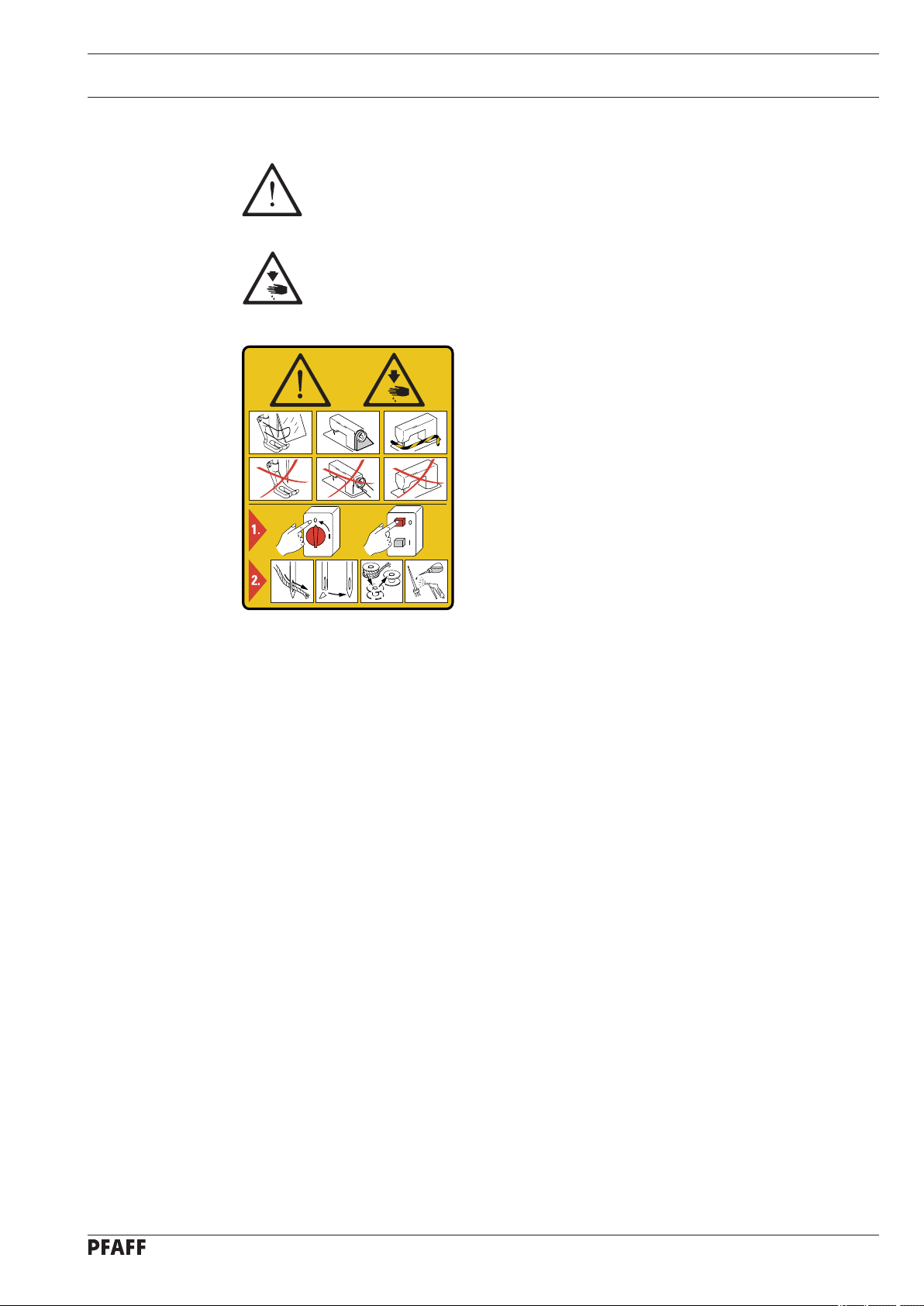
1.03 Safety symbols
Danger!
Points to be observed..
Danger of injury for operating and specialist personnel!
Do not operate without finger guard and safety devices.
Before threading, changing bobbin and needle, cleaning
etc. switch off main switch.
Caution
1.04 Important points for the user
This Instruction Manual is an integral part of the machine and must be available to the
●
operating personnel at all times.
The Instruction Manual must be read before operating the machine for the first time.
●
The operating and specialist personnel is to be instructed as to the safety equipment of
●
the machine and regarding safe work methods.
It is the duty of the user to only operate the machine in perfect running order.
●
It is the obligation of the user to ensure that none of the safety mechanisms are removed
●
or deactivated.
It is the obligation of the user to ensure that only authorized persons operate and work
●
on the machine.
Further information can be obtained from your PFAFF agent.
7
Page 8

Safety
1.05 Operating and specialist personnel
1.05.01 Operating personnel
Operating personnel are persons responsible for the equipping, operating and cleaning of
the machine as well as for taking care of problems arising in the sewing area.
The operating personnel is required to observe the following points and must:
always observe the Notes on Safety in the Instruction Manual!
●
never use any working methods which could adversely affect the safety of the machine!
●
●
not wear loose-fitting clothing or jewelery such as chains or rings!
also ensure that only authorized persons have access to the potentially dangerous area
●
around the machine!
always immediately report to the person responsible any changes in the machine which
●
may limit its safety!
1.05.02 Specialist personnel
Specialist personnel are persons with a specialist education in the fields of electrics, electronics and mechanics. They are responsible for the lubrication, maintenance, repair and adjustment of the machine.
The specialist personnel is obliged to observe the following points and must:
always observe the Notes on Safety in the Instruction Manual!
●
●
switch off the On/Off switch before carrying out adjustments or repairs, and ensure that
it cannot be switched on again unintentionally!
wait until the luminous diode on the control box is no longer blinking or on before begin
●
ning adjustment or repair work.
never work on parts which are still connected to the power supply! Exceptions are explai
●
ned in the regulations EN 50110.
●
replace the protective coverings and close the electrical control box afer all repairs or
maintenance work!
-
-
8
Page 9
Safety
1.06 Danger
A working area of
chine while it is in operation so that it is always easily accessible.
Never reach into the sewing area while sewing!
Danger of injury by the needle!
Never leave objects on the table while adjusting the machine settings!
Objects can become trapped or be slung away! Danger of injury!
1 meter is to be kept free both in front of and behind the ma-
1
5
3
4
Fig. 1 - 01
2
Do not operate the machine without its take-up-lever guard 1!
Danger of injury due to the motion of the take-up lever!
Do not operate the macine without finger deflector
Danger of injury by the needle!
Do not operate the machine without eye shield
Danger of injury from flying needle or button fragments!
Only operate the machine with cover
4 closed!
2!
3!
Danger of injury from rotating hook!
Do not operate the machine without cover
Danger of injury from moving parts!
5!
9
Page 10

Proper use
2 Proper use
The PFAFF 3371-10/.. is used for attaching buttons to articles of clothing automatically.
Any and all uses of this machine which have not been approved of by the
manufacturer are considered to be inappropriate! The manufacturer cannot be
held liable for any damage caused by the inappropriate use of the machine!
The appropriate use of the machine includes the observance of all operational,
adjustment, maintenance and repair measures required by the manufacturer!
10
Page 11

Specifications
3 Specifications
Max. sewing speed: ............................................................................................... 2500 spm
Feed type: .............................................................................................................. intermittent
Stitch length: ...................................................................................................... 0.1 – 10.0 mm
Stitch type: ........................................................................................................ 301 (lockstitch)
Needle size in 1/100 mm:
for fine materials: ......................................................................................................... 70 - 100
for medium-weight materials: .................................................................................... 100 - 120
Needle system: ................................................................................................................DPx17
Needle bar stroke: ...........................................................................................................41mm
Fabric clearance: ................................................................................................... max. 13 mm
Max. size of sewing area: ....................................................................................6,5 x 6,5 mm
Power supply: ................................................................. 220 V ± 10%, 50/60 Hz, single phase
Power consumption: ...................................................................................................0.55 kVA
Electrical power rating: ................................................................................................ 1,2 kVA
Fuse protection: ...................................................................................................1x 16 A, inert
▲
-1
Noise data:
Noise emission level at workplace
with a sewing cycle of 4 sec. on and 2 sec. off: ...............................................LpA = 74 dB(A)
(Noise measurement in accordance with DIN 45 635-48-B-1, ISO 11204, ISO 3744, ISO
4871)
Sewing head dimensions:
Length: ............................................................................................................approx. 700 mm
Width: .............................................................................................................. approx. 220 mm
Height: ............................................................................................................ approx. 380 mm
Dimensions of standard base:
Length: .......................................................................................................... approx. 1060 mm
Width: .............................................................................................................. approx. 600 mm
Height: ............................................................................................................ approx. 820 mm
Weights
Sewing head: ................................................................................................... approx. 42 kilos
Base incl. control box: ...................................................................................... approx. 45 kilos
■
▲
Subject to alterations
■
KpA = 2,5 dB
11
Page 12

Disposal of Machine
4 Disposal of Machine
Proper disposal of the machine is the responsibility of the customer.
●
The materials used for the machine are steel, aluminium, brass and various plastic
●
materials. The electrical equipment comprises plastic materials and copper.
The machine is to be disposed of according to the locally valid pollution control regula-ti
●
ons; if necessary, a specialist ist to be commissioned.
Care must be taken that parts soiled with lubricants are disposed of separately
according to the locally valid pollution control regulations!
-
12
Page 13

Transportation, packing and storage
5 Transportation, packing and storage
5.01 Transportation to customer‘s premises
The machines are delivered completely packed.
5.02 Transportation inside the customer‘s premises
The manufacturer cannot be made liable for transportation inside the customer‘s premises
nor to other operating locations. It must be ensured that the machines are only transported
in an upright position.
5.03 Disposal of packing materials
The packing materials of this machine comprise paper, cardboard and VCE fibre. Proper disposal of the packing material is the responsibility of the customer.
5.04 Storage
If the machine is not in use, it can be stored as it is for a period of up to six months, but It
should be protected against dust and moisture.
If the machine is stored for longer periods, the individual parts, especially the surfaces of
moving parts, must be protected against corrosion, e.g. by a film of oil.
13
Page 14

Explanation of symbols
6 Explanation of symbols
In this instruction manual, work to be carried out or important information is accentuated by
symbols. These symbols have the following meanings:
Note, information
Cleaning, care
Lubrication
Maintenance, repairs, adjustment, service work
(only to be carried out by technical staff)
14
Page 15
Control elements
0
7 Control elements
7.01 Main switch
Switch the machine on or off by turning
●
main switch 1.
Fig. 7 - 01
7.02 Pedal
1
The pedal is used to lower and raise
●
the button clamp, and to start the sewingprogram.
After switching the machine on,
first press the "TE" key to bring
the machine into its neutral po
sition.
-
0
+1
-1 = sewing interruption
0 = neutral position
+1 = lower button clamp
+2 = sewing
+2
-1
Fig. 7 - 02
15
Page 16
Control elements
7.03 Balance wheel
By pressing and holding down balance
●
wheel 1, it is possible to adjust the needle bar manually.
1
Fig. 7 - 03
7.04 Lever for adjusting the button clamp size
●
1
2
Adjust lever 1 to set the size of the button clamp. To do so, loosen screw 2.
After screw 2 has been loosened, the clamp jaws close automatically! Danger of crushing in
the button clamp zone!
16
Fig. 7 - 04
Page 17
Control elements
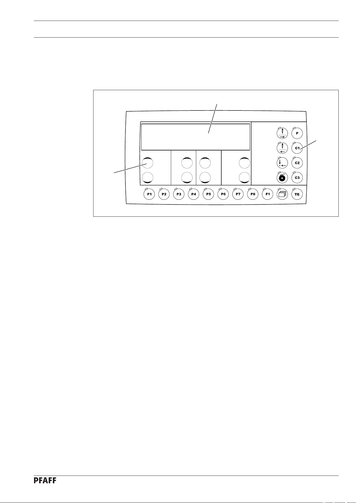
7.05 Control panel
The control panel is used to select seam programs, call up machine functions, change
parameters, control the different operating modes, as well as for reading error signals and
service settings.
1
2
3
Fig. 7 - 05
The control panel consists of display screen
display 1 consists of a two-row alphanumerical LCD display with 16 symbols per row. The
function keys 2 are located below and to the right of the display screen. The status of the
function keys and the machine operating modes are shown with LEDs in the corresponding
keys. Every time the function keys 2 are operated, a key tone sounds as confirmation of the
input. If the input required is invalid, e.g. because the max. permissible value for the
parameter input has been reached, a double tone is audible. An SD-card reader for data
transfer is integrated.
7.05.01 Screen displays
Depending on the operating mode, on the screen 1 information is shown about the machine
status, program selection, sequence program progress, input parameters, as well as error signals (also see Chapter 11 Input).
Depending on the operating mode, relevant data is displayed in combination with the ap-
●
propriate symbol or text, and can be altered directly.
1 with the function keys described below. The
When the parameters are entered, the number of the parameter selected is shown with
●
the corresponding parameter value, see Chapter 11.03 Parameter input.
If faults occur in the sewing operation, a corresponding error signal appears in the display,
●
see Chapter 11.09 Error messages on the display
17
Page 18
Control elements
7.05.02 Display symbols
Program number
Speed
X Size factor X-direction (crosswise) in %
Y Size factor Y-direction (lengthwise) in %
Bobbin thread counter / piece counter
Enter
Machine memory
SD-memory card
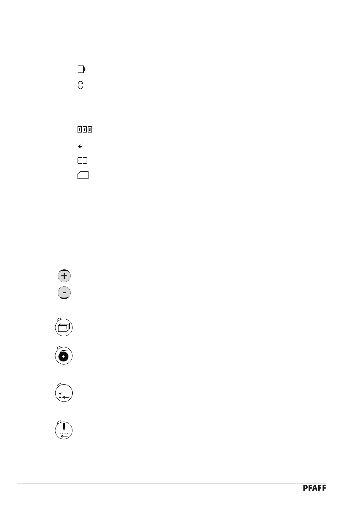
7.05.03 Function keys
The functions keys described below are used essentially to switch machine functions on and
off. When the function is switched on, the diode in the key is illuminated
If a corresponding value has to be fixed for the activated function, this can be carried out
with the corresponding +/- keys
By pressing and holding the corresponding +/- key, firstly the numerical value displayed abo
ve it is altered slowly. If the +/- key is pressed longer, the numerical value changes more
quickly. The respective +/- keys shown opposite are described below.
Menü
This function is used in the respective operating mode to scroll within the existing menus.
Wind
The bobbin thread winding function is called up, see Chapter 9.03 Winding the bobbin
thread.
Basic position
Button clamp and needle are positioned in the basic position and , if necessary, the thread
trimming function is activated.
.
3.
-
18
Tacting backwards
Each time the key is pressed, the selected seam program is sewn stitch by stitch in reverse,
and the coordinates for each stitch are shown on the control panel.
Page 19
Control elements
Tacting forwards
Each time the key is pressed, the selected seam program is sewn forwards stitch by stitch,
and the coordinates for each stitch are shown on the control panel.
to
to
Program stations
The function keys P1 to P8 are used to enter and select seam programs, see Chapter
9.06.02 Selecting the program station.
Direct program selection
This function is used to select a seam pattern. After selection, speed and size can be altered, see Chapter 9.06.01 Selecting and altering the seam pattern.
Sequences
The function keys C1 to C3 are used to enter and select sequences, see Chapter 9.06.03
Selecting a sequence.
TE
In the sewing mode, this key is used to change to the input mode. In the input mode this
key is used to acknowledge the input of program stations and sequences, and to change
into the sewing mode.
19
Page 20
Installation and commissioning
8 Installation and commissioning
The machine must only be installed and commissioned by qualified personnel!
8.01 Installation
The site where the machine is installed must be provided with suitable connections for the
electric current, see Chapter 3 Specifications.
It must also be ensured that the standing surface of the machine site is firm and horizontal,
and that sufficient lighting is provided.
All relevant safety regulations must be strictly adhered to!
If the machine is delivered without a table, be sure to use a stand and table top
that can hold the weight of the machine with its motor.
It is very important to ensure that the stand of the machine is firm and steady,
also during sewing.
For packing and transportation reasons the table top is in the lowered position.
The table height is adjusted as described below.
If the machine is delivered with stand, the transit lock must be removed before
commissioning, see Chapter 8.01.02 Removing the transit lock.
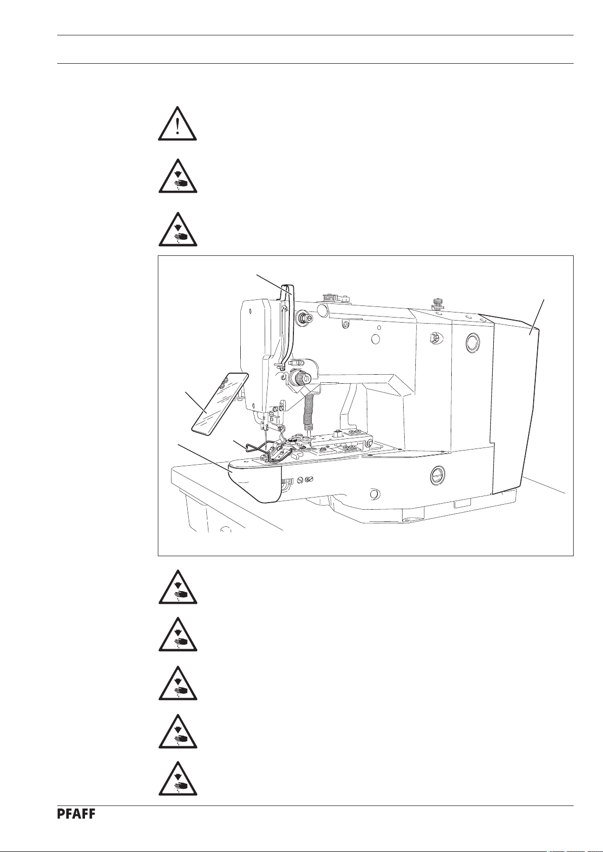
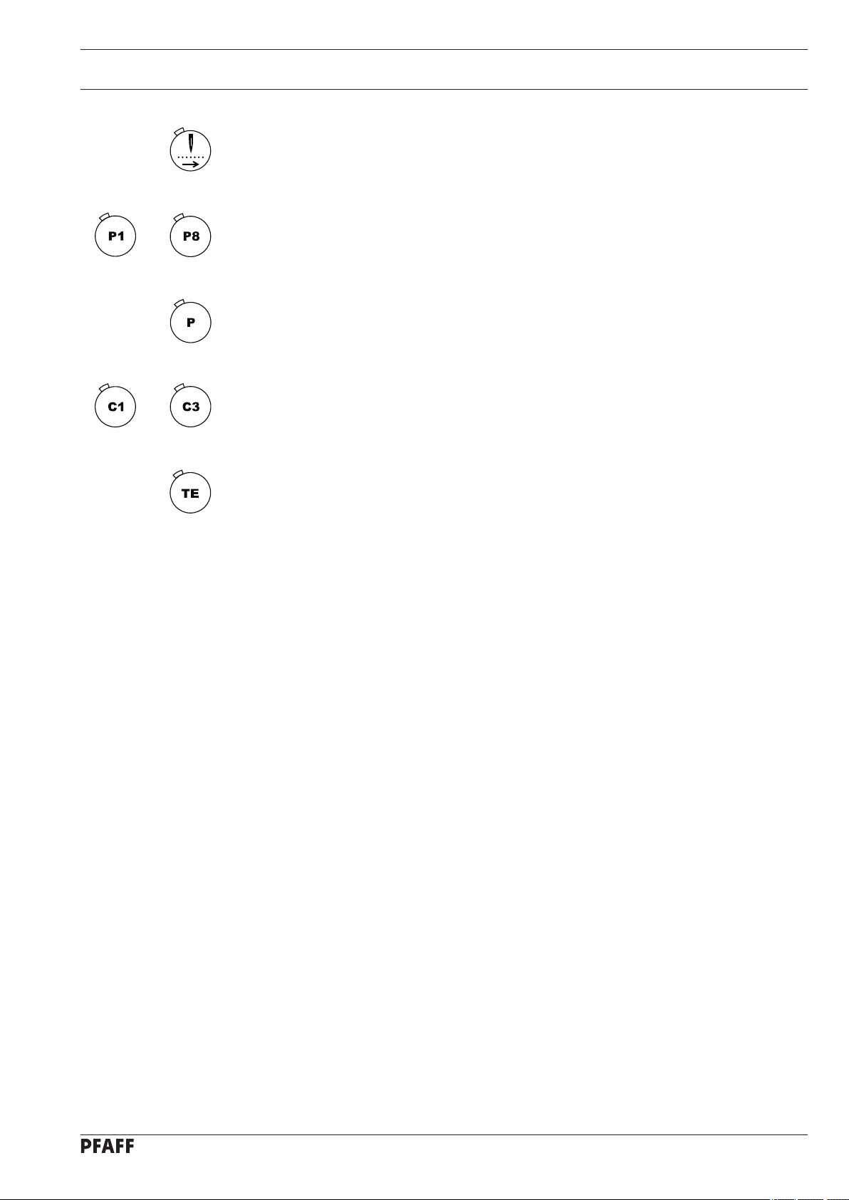
8.01.01 Adjusting the table height
1
Fig. 8 - 01
1
2
20
Loosen screws 1 and 2 and set the table height as required.
●
Firmly tighten screw 1.
●
Set the required pedal position and tighten screw
●
2.
Page 21

8.01.02 Removing the transit lock
Installation and commissioning
Loosen nut 1.
●
Fig. 8 - 02
Remove screw
●
2.
1
2
8.01.03 Fitting the reel stand
Fig. 8 - 03
Fit the reel stand as shown in Fig. 8 - 03.
●
Afterwards insert the stand in the hole in
●
the table top and secure it with nuts provided.
21
Page 22
Installation and commissioning
8.01.04 Mounting the table top (for deliveries without stand)
5
3
3
4
6
1
2
Fig. 8 - 04
Drill holes in the table top as shown in the drawing, see Chapter 8.01.05 Table top drill
●
hole plans.
Screw on the oil outlet 1.
●
Screw the oil tank
●
Set the rubber pads
●
table top.
Set support 5 in the appropriate hole.
●
Place wick
●
6 iin the holders of oil pan 4.
2 to oil outlet 1.
3 in the fastening holes of the oil pan 4 and screw oil pan 4 to the
22
Page 23
8.01.05 Table top drill hole plans
Top view
Installation and commissioning
Control panel holdersr
23
Transit lock
Page 24
Installation and commissioning
Bottom view
Gestell 906-3550-005/895
Drawer
24
Controller
Main switch
Speed control unit
Stand 906-3550-005/895
Page 25

Installation and commissioning
106-051
8.01.06 Connecting the plug-in connections and earth cable
A
1
B
Fig. 8 - 05
Connect all plugs as labelled in the control box.
●
Screw the earth cable from the machine and the main switch to earth point
●
Connect earth point A and earth point B with an earth cable.
●
●
Screw the earth cable of plug
1 to earth point B.
8.02 Commissioning the machine
Clean the machine thoroughly.
●
Check the oil level, see Chapter 12
●
●
Check the machine, especially the electric wires, for any damage.
●
Have specialists check, whether the machine’s motor can be used with the existing
mains voltage.
Circuit diagrams, see Chapter 13.
A.
Care and Maintenance.
8.03 Switching the machine on/off
Switching the machine on/off, see Chapter 7.01 Main switch.
●
25
Page 26

Setting up
9 Setting up
All instructions and regulations in this instruction manual must be observed.
Special attention must be given to all safety regulations!
All setting-up work must only be done by personnel with the necessary
training. For all setting-up work the machine must be isolated from its powe
supply by turning off the on/off switch or removing the machine plug from the
electric power socket!
9.01 Inserting the needle
2
1
Switch off the machine!
Danger of injury if the machine
is started accidentally!
Only use needles from the sys
tem intended for the machine,
see Chapter 3 Specifications.
Loosen screw 1.
●
Insert the needle as far as possible. The
●
long needle groove (see arrow) must be
facing forwards.
-
Fig. 9 - 01
Tighten screw 1.
●
Through hole 2 it is possible to check whether the needle has been inserting as
far as possible.
Broken needles can be removed by inserted suitable tools in hole 2.
26
Page 27

Setting up
9.02 Threading the needle thread / adjusting the needle thread tension
1
2
Fig. 9 - 02
Switch off the machine!
Danger of injury if the machine is started accidentally!
Thread the needle thread as shown in
●
Adjust the needle thread tension by turning milled nuts
●
Fig. 9-02.
1 and 2.
27
Page 28

Setting up
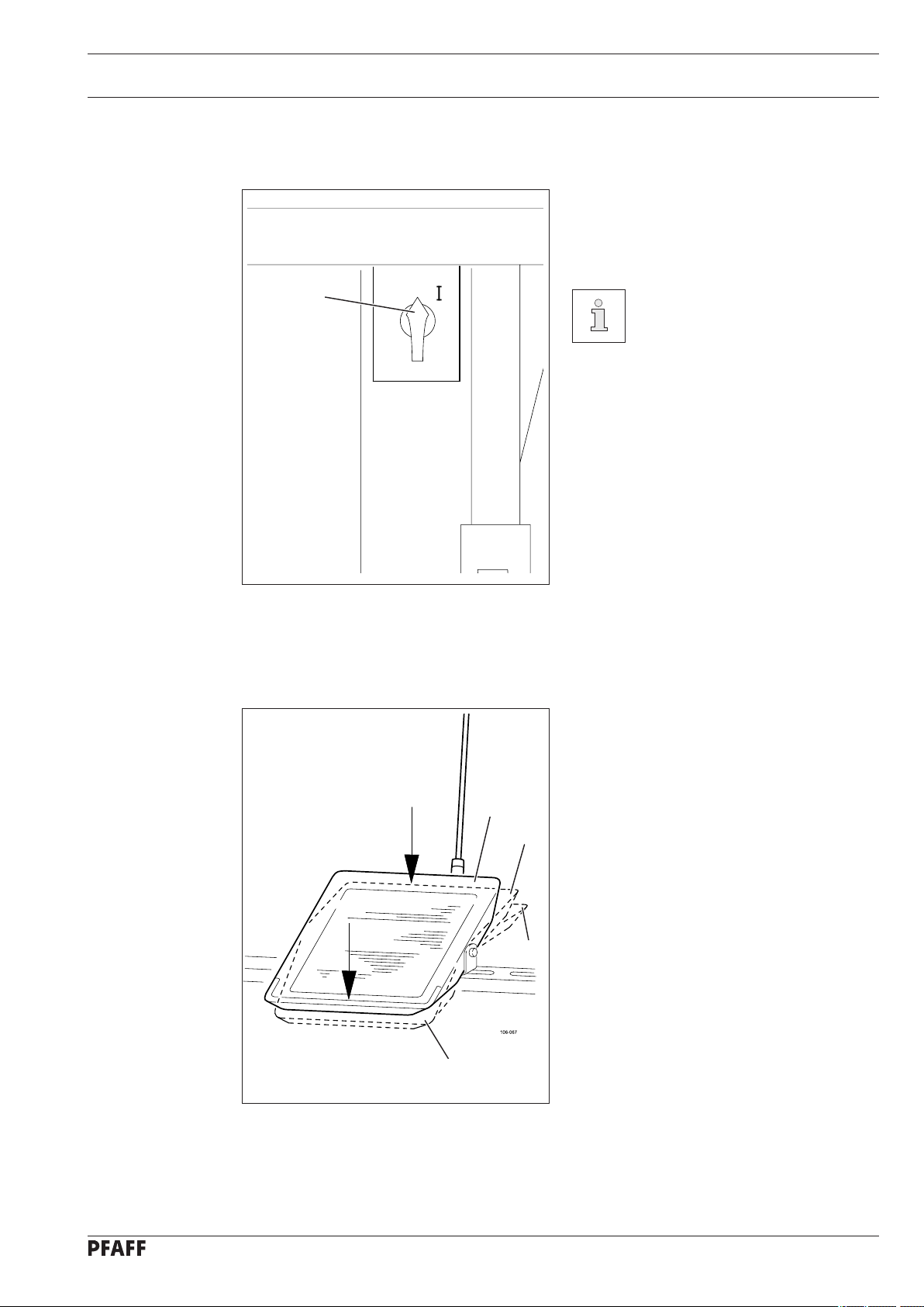
9.03 Winding the bobbin thread
3
6
2
1
5
4
Fig. 9 - 03
Place the empty bobbin 1 on the bobbin winder spindle 2.
●
Thread the thread as shown in
●
anti- clockwise direction.
Set the preliminary thread tension by turning milled screw
●
Press lever
●
4 in the direction of the arrow until it clicks into place.
The bobbin is filled during sewing.
Fig. 9-03 and wind it round bobbin 1 a few times in the
3.
28
Winding is also possible as follows:
●
●
Switch on the machine and press the key for winding
●
Remove the thread from the needle and take-up lever.
Operate the pedal to carry out winding, the bobbin winder stops automatically as soon as
●
the bobbin is adequately full.
Press the key for winding, the machine stops.
●
Thread the machine again.
●
Adjusting the amount of thread on the bobbin
Loosen screw 5.
●
Set stop 6 so that the bobbin winder switches off automatically when the thread is still
●
ca. 1 mm from the edge of the bobbin.
Tighten screw
●
5.
.
Page 29

Setting up
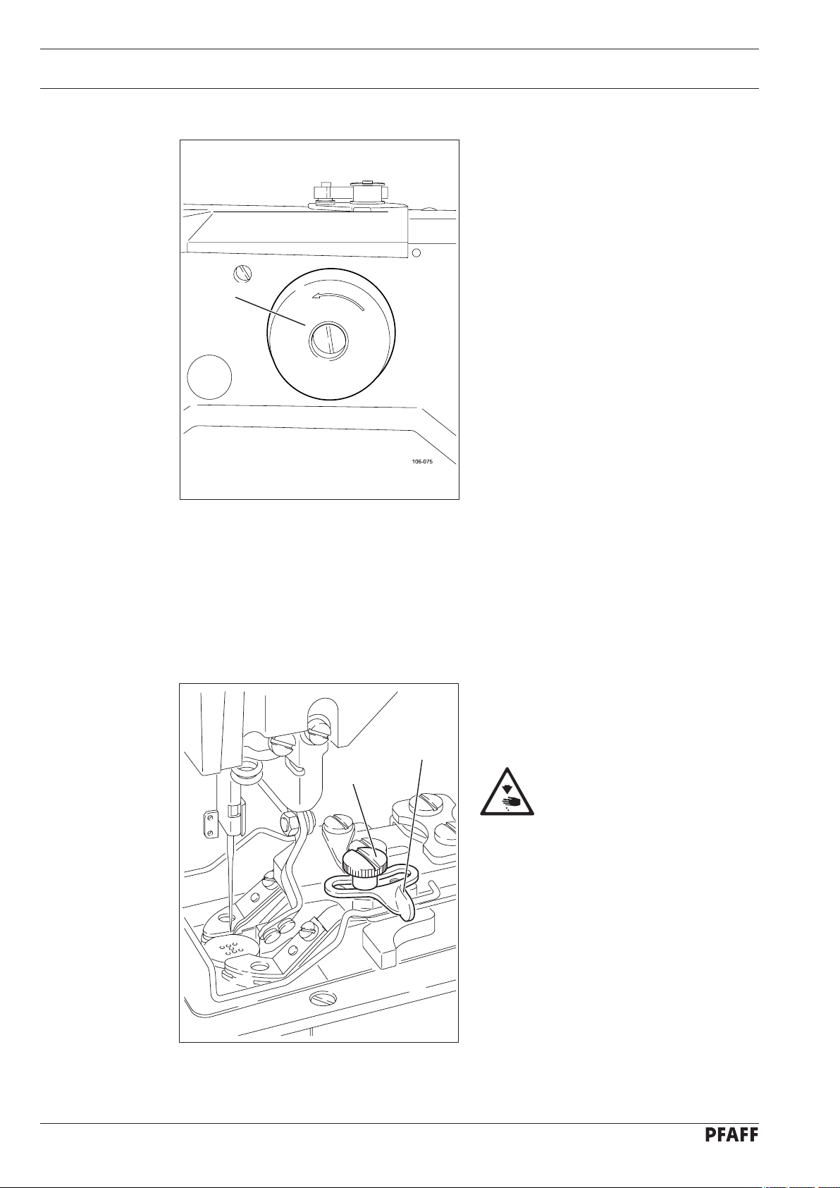
9.04 Removing / replacing the bobbin case
Switch off the machine.
Danger of injury if the machine
starts accidentally!
2
1
Fig. 9 - 04
Removing the bobbin case
Open the hook cover
●
Pull out latch
●
Remove bobbin case
●
Replacing the bobbin case
Push bobbin case
●
base until you feel it click into place
Close the hook cover
●
1
2
2 into the bobbin case
.
9.05 Threading the bobbin thread / adjusting the bobbin thread tension
Fig. 9 - 05
Place the bobbin into the bobbin case,
●
so that this turns in the direction shown
1
by the arrow when the thread is pulled.
Insert the thread as shown in
●
Set the thread tension by turning
●
screw 1.
Fig. 9-05.
29
Page 30

Setting up
9.06 Selecting a seam program
9.06.01 Selecting and changing the seam pattern.
To avoid the machine starting accidentally, to begin with the TE key must be pressed, after the machine has been switched on. The machine is then in its basic position and offers a
number of possibilities for selecting seam programs.
- Direct selection of the seam pattern and its individual adaptation by changing the speed
and size factors.
- Selection of the seam program via a program station. For this purpose a seam pattern with
its respective speed and corresponding size factors must have been stored previously.
- With the selection of a sequence several seam programs are sewn after each other. For
this purpose a sequence must have been compiled beforehand from individual seam pro
grams (program stations).
X
Y
With the machine in the basic position, select the direct seam pattern.●
X Y
11 250 0 100 10 0
With the corresponding +/- key select the desired seam pattern, e.g. 11. The seam pat-
●
terns are stored in the machine under program numbers, see Chapter 11.06
the seam patterns.
Select the desired speed with the corresponding +/- key
●
Enter the desired size factor (in %) (X-direction) with the corresponding +/- key
●
Enter the desired size factor (in %) (Y-direction) with the corresponding +/- key
●
●
Conclude the input by pressing the TE key. (The machine changes to the sewing mode).
.
Summary of
.
.
30
The enlargement of the seam pattern is limited by the size of the machine’s se
wing area.
The altered speed and size factors entered are not stored when the machine
changes to another seam program. If you wish to store these values, a station
key must be reserved with the corresponding seam program, see Chapter 11.01
Reserving program stations.
-
Page 31

Setting up
9.06.02 Selecting a program station.
With the machine in its basic position, select the desired program station, e.g. P3.●
X Y
20 220 0 90 110
Only those program stations can be selected, which have been reserved previously with a seam pattern with its respective speed and size factors, see
Chapter 11.01 Reserving program stations.
Speed and size factors cannot be changed directly in a seam program selected
via a program station.
9.06.03 Selecting a sequence
With the machine in its basic position, select the desired sequence, e.g. C2.●
A 3 - 3 - 3 - 3 - 3 - 3 - 8
8 - 8 - 8 - 4 - 4
The next seam program waiting to be sewn is depicted by the relevant flashing
entry.
Sequences can only be called up if they have been created beforehand (see
Chapter 11.02.01 Enter sequences).
31
Page 32

Setting up
9.07 Adjusting the size of the sewing area
A comparison between the sewing area size
entered and the actual sewing area size of
the button clamp ensures that seam programs, which are not within the sewing area
1
size, cannot be sewn.
X
Fig. 9 - 06
With the machine in its basic position, select the input mode. (LED is illuminated).●
Y
No VAL
023 -23 23
If the actual and the entered se
wing area size do not concur
with each other, severe damage
can be caused to the machine!
Measure the sewing area size of button
●
clamp 1.
-
32
With the corresponding +/- key select parameter "023".
●
If required, enter the access code, see Chapter 11.05.01 Entering the access code.
●
With the corresponding +/- key enter the measured value (in 1/10
●
X-axis.
With the corresponding +/- key
●
With the corresponding +/- key enter the measured value (in 1/10
●
Y-axis.
Conclude the input by pressing the TE key. (Machine changes to the sewing mode).
●
select parameter "024".
mm) for the
mm) for the
Page 33

Setting up
9.08 Setting up the bobbin thread counter
With the machine in its basic position, select the input mode.
●
With the corresponding +/- key
●
If required, enter the access code, see Chapter 11.05.01 Entering the access code.
●
No VAL
0 04 ON 800
●
With the corresponding +/- key switch on the bobbin thread counter.
●
With the corresponding +/- key enter the number of workpieces to be sewn.
Conclude the input by pressing the TE key. (Machine changes to the sewing mode).
●
select parameter "004".
9.09 Resetting the piece counter
In the sewing mode (basic position of the machine) the piece counter or the bobbin thread
counter can be displayed by pressing the menu key. (When the bobbin thread counter is
switched off, the piece counter is displayed - Selection under parameter 004) .
20 SET 0
The piece counter counts from 0 onwards and differs from the bobbin thread counter in the
display through the upwards pointing arrow.
Reset the piece counter with the corresponding +/- keys. ●
33
Page 34

Setting up
9.10 Shifting the seam pattern
To adapt the seam patterns to formed workpiece holders, selected seam patterns can be
shifted.
From the basic position of the machine select the desired program station, e.g. P1.
●
Tact through the seam pattern, e.g. forwards.
●
The actual coordinates are shown together with the shift values for each stitch.
X: Y:
169+0 -99+10
With the corresponding +/- keys it is possible to enter a shift value for the entire seam
●
pattern in X- or Y-direction at each seam pattern coordinate.
The seam pattern shift is allocated to the respective actual program station and
is deleted when the program number is changed.
34
Page 35

Setting up
9.11 Inserting and removing the SD-memory card
Inserting the SD-memory card
Open cover 1.
●
1
Insert SD-memory card
●
slot with the label at the front.
2 into the card
Fig. 9 - 08
Close cover
●
2
Removing the SD-memory card
Open cover 1.
●
Press the edge of the SD-memory card
●
lightly – the SD-card is ejected.
Close cover
●
1 again.
1 again.
3
By moving slide
the write protection function of the SD-memory card. To store, process or
delete data on the SD-memory card, the write protection function must be
deactivated.
3 it is possible to activate (position "LOCK") or deactivate
2
35
Page 36

Sewing
10 Sewing
The machine must be installed, connected and set up as described in Chapter 8
Installation and Commissioning.
4
Fig. 9 - 02
The machine must not be operated without the safety devices
ter 1.06 Danger warnings! Danger of injury!
1
3
2
1 to 5, see Chap-
5
10.01 Operating cycle
Carry out all steps in accordance with Chapter 9 Setting up.
●
Place the material properly under the button clamp.
●
Lower the button clamp and start the sewing cycle, see Chapter 7.02 Pedal
●
10.02 Sewing in the "Direct program selection" mode
In this function, a seam pattern is selected. After selection, the speed and size can be altered, see Chapter 9.06.01 Selecting and changing the seam pattern.
10.03 Sewing in the "Program stations" mode
Program stations can be selected, which have been reserved beforehand with a seam pattern with relevant speed and size factors, see Chapter 11.01 Reserving program stations.
.
36
Page 37

Sewing
10.04 Sewing in the "Sequences mode".
Sequences, which have been created beforehand, can be called up with the function keys
C1 to C3 (see Chap. 11.02.01 Entering sequences)
10.04.01 Interrupting a sequence
If an interruption occurs during a sequence cycle (e.g. broken thread), it is possible to
continue at the same sequence point after the error has been eliminated.
The procedure is as follows:
A 3 - 3 - 3 - 3 - 3 - 3 - 8
8 - 8 - 8 - 4 - 4
●
The activated sequence point flashes.
Select the sequence A, B or C by pressing the left +/- key.
●
Press the corresponding +/- key to move to the sequence point to be repeated.
●
Conclude input by pressing the TE key
●
10.05 Error messages
When an error occurs, the text "ERROR" appears on the display together with an error
code and short instructions. In addition the diode in the memory card slot lights up red
(see arrow). An explanation of the error codes can be found in the Chapter 11.09 Error
messages on the display.
.
ERROR: 0 03
RESET
Correct the error.
●
Acknowledge the correction of the error by pressing the corresponding +/- key or by
●
switching the machine off and on.
The diode in the memory card slot (see arrow) turns yellow again
●
37
Page 38

Input
11 Input
After the machine has been switched on, it is in the input mode. The LED in the "TE" key is
illuminated. The input mode is used to reserve program stations, to enter sequences and to
change machine parameters. In addition information and input possibilities for the service
area are available in this mode.
11.01 Reserving program stations
to
to
The station keys P1 to P8 are used to enter and select seam programs. A complete seam
program is configured from the following parameter:
- seam pattern
- speed
- size factor in X-direction
- size factor in Y-direction
Call up the input mode by pressing the TE key (LED is illuminated).
●
Press a station key to call up the direct seam pattern selection function.
●
X Y
20 220 0 90 110
With the corresponding plus/minus key select the desired seam pattern, e.g. 20. The
●
seam patterns are stored in the machine under program numbers, see Chapter 11.06
Summary of the seam patterns.
38
X
Y
Select the desired speed with the corresponding +/- key
●
Enter the desired size factor (in %) (X-direction) with the corresponding +/- key
●
Enter the desired size factor (in %) (Y-direction) with the corresponding +/- key.
●
The enlargement of the seam pattern is limited by the size of the machine’s
sewing area.
●
Conclude the input by pressing the TE key. (The machine changes to the sewing mode).
.
.
Page 39

Input
11.02 Sequences
.02.01 Entering sequences
11
to
2x
The sequence program keys C1 to C3 are used to enter and select sequence programs. The
sequence programs are put together from seam programs, which have been deposited under the station keys P1 to P8.
A sequence can consist of up to 3 segments (A, B + C). In each segment up to
14 entries can be made.
Call up the input mode by pressing the TE key (LED is illuminated).
●
In the input mode, select the desired sequence program key, e.g.
●
Enter the desired seam programs in any order by using the station keys, e.g. P3
●
P8 four times,
P4 twice
Press the TE key input twice (machine changes to the sewing mode).
C2.
six times ,
A 3 - 3 - 3 - 3 - 3 - 3 - 8
8 - 8 - 8 - 4 - 4
The station keys for selection must have been reserved beforehand, see
Chapter 11.01 Reserving program stations.
In the "Input" mode it is possible to scroll between the sequence zones
A, B and C by pressing the Menu key.
11.02.02 Checking the sequence contents
With the machine in its basic position, select the desired sequence, e.g. C2.
●
The activated sequence point flashes.
●
Press the corresponding +/- key to move to the sequence point to be checked (e.g. 8).
●
39
Page 40

Input
A 3 - 3 - 3 - 3 - 3 - 3 - 8
8 - 8 - 8 - 4 - 4
(LED is not illuminated).
2x
●
Press the TE key
The parameters, such as number of the seam pattern, speed and size factors of the flas
●
hing sequence entry are shown if the Menu key is pressed.
Quit the check mode by pressing the Menu key twice.
●
11.02.03 Deleting sequences
Call up the Input mode by pressing the TE key (LED is illuminated).
●
Call up the sequence to be changed by pressing the
to
●
Deleting individual entries
Press a +/- key to set the cursor beneath the entry to be deleted and delete the entry by
●
pressing the reverse tacting key twice.
-
C1, C2 or C3 keys.
Inserting individual entries
Press a +/- key to set the cursor beneath the position for the insertion.
●
Insert the desired entry by pressing the corresponding station key.
to
2x
●
Deleting a complete sequence
Press a +/- key to set the cursor at the beginning of the sequence. Press the reverse
●
tacting key as often as necessary to delete all entries on the display.
Press the
●
TE input key twice (machine changes to the sewing mode).
11.02.04 Combining sequences
Several sequences can be combined to one seam program. To carry out the adjustment,
enter the corresponding value for parameter 005 (see Chapter 11.08 List of parameters).
40
Page 41

Input
11.03 Parameter input
After the machine has been switched on, it is in the input mode..
No VAL
001 2500
●
With the corresponding +/- key select the desired parameter, e.g. 003 lock seam
patterns.
No VAL
0 03 1: ON
●
With the corresponding +/- key select the desired seam pattern.
No VAL
0 03 3: OFF
●
With the corresponding +/- key lock the desired seam pattern.
Conclude the input by pressing the TE key. (The machine changes to the sewing mode).
●
There is a list explaining all the parameters in Chapter 11.08 List of parameters
41
.
Page 42

Input
11.04 Free input of the seam pattern (Teach in))
In addition to the selection of firmly stored seam patterns (see Chapter 11.06 Summary of
the seam patterns), there is also a possibility of setting seam patterns (button type) as desired using the corresponding parameter input.
The program numbers
terns.
Call up the Input mode by pressing the TE key
No VAL
0 01 25 00
With the corresponding +/- keys, select the parameter 201 to enter the program number.●
No VAL
201 50
P50 to P99 are reserved for the free input of seam pat-
(LED is illuminated).●
42
With the corresponding +/- keys, select the desired program number.
●
With the corresponding +/- keys
●
With the corresponding +/- keys, select the desired button type.
●
(2 = two-hole button, 3 = three-hole button, 4 = four-hole button)
With the corresponding +/- keys
●
ordinates of the buttonholes 1 - 6, and enter the relevant values for the X- and Y-direction.
If necessary, with the corresponding +/- keys
●
number of stitch positions and enter the desired value.
If necessary, with the corresponding +/- keys
●
stitch formation.
The stitch formation can only be chosen for three- and four-hole buttons and depends on
the previously selected button type.
, select the parameter 202 to enter the button type.
, select the parameters 203 - 208 in turn to enter the co-
, select the parameter 209 to enter the
, select the parameter 210 to choose the
Page 43

Input
1
3
2
1
3
2
1
2
4
3
2
1
4
3
2
4
1
3
Stitch formations for the three-hole button
Seam cycle
Value for parameter 210 = 0
Point
Value for parameter 210 = 1
Stitch formations for the four-hole button
Normal
Value for parameter 210 = 0
Seam cycle
Value for parameter 210 = 1
Arrow
Value for parameter 210 = 2
Z
Value for parameter 210 = 3
Select the desired stitch formation with the corresponding +/- key
●
If necessary, select parameter 211 with the corresponding +/- keys and activate the inter
●
.
mediate trimming function.
The intermediate trimming function can only be activated for four-hole buttons. When
the function is activated, the thread is trimmed between the second and third hole of the
button.
With the corresponding +/- keys
●
of sewing-on stitches.
●
call up parameter 212 and enter the number
-
With the corresponding +/- keys
●
of attaching stitches.
●
call up parameter 213 and enter the number
A summary with explanations of all the parameters can be found in Chapter
11.08
List of parameters..
43
Page 44

Input
11.05 Access codes
The selection of seam patterns, the reservation of the program stations, the input of
sequences and the selection of individual parameter levels can be locked with a 4-figure
access code. The access code can be changed as desired. The factory set access code
is "3371".
11.05.01 Entering the access code
If, in the input mode, a function is selected, which has an access code, the demand for
entering the access code appears on the display.
PINCODE:
3 3 7 1
●
Enter the access code with the corresponding +/- keys.
Conclude the input by pressing the TE key (machine changes to the sewing mode).
●
Once the access code has been entered, all functions with access protection
are freely accessible, until the machine is switched off.
11.05.02 Changing the access code
In the input mode, select parameter "811"
●
Enter the access code, see Chapter 11.05.01 Entering the access code
●
No VAL
811 3371
44
Change the access code with the corresponding +/- keys.
●
Conclude the input by pressing the TE key (machine changes to the sewing mode).
●
Page 45

Input
11.05.03 Granting access rights
In the input mode select the corresponding parameter ("801" to "806"), see
●
Chapter 11.08 List of parameters.
If required, enter the access code, see Chapter 11.05.01 Entering access codes.
●
No VAL
801 OFF
With the corresponding +/- key approve (on) or lock (OFF) access..
●
Conclude the input by pressing the TE key (machine changes to the sewing mode).
●
45
Page 46

Input
11.06 Summary of the seam patterns
No. Seam pattern Size of
sewing area [mm]
P1 3,4 x 3,4 6 18
P2 3,4 x 3,4 8 22
P3 3,4 x 3,4 10 26
P4 3,4 x 3,4 12 22
P5 3,4 x 3,4 6 22
Penetrations/
button row
Total number
of stitches
P6 3,4 x 3,4 8 26
P7 3,4 x 3,4 8 26
P8 3,4 x 3,4 12 3
P9 3,4 x 3,4 6 18
P10 3,4 x 3,4 8 22
46
P11
3,4 x 3,4 10 26
Page 47

Input
No. Seam pattern Size of
sewing area [mm]
Penetrations/
button row
Total number
of stitches
P12 3,4 x 3,4 6 18
P13
3,4 x 3,4 8 22
P14 3,4 x 3,4 10 26
P15
3,4 x 3,4 6 22
P16 3,4 x 3,4 8 26
P17
3,4 x 3,4 10 30
P18 3,4 x 0,0 6 11
P19
3,4 x 0,0 8 13
P20 3,4 x 0,0 10 15
P21 3,4 x 0,0 12 17
P22 3,4 x 0,0 16 21
47
Page 48

Input
No. Seam pattern Size of
sewing area [mm]
P23 0,0 x 3,4 6 11
P24 0,0 x 3,4 10 15
P25 0,0 x 3,4 12 17
P26 3,4 x 3,4 6 18
P27 3,4 x 3,4 10 26
Penetrations/
button row
Total number
of stitches
P28 3,4 x 3,4 6 22
P29 3,4 x 0,0 10 30
P30 3,4 x 0,0 5 20
P31 3,4 x 0,0 8 29
P32 3,4 x 0,0 5 20
48
P33 3,4 x 0,0 8 29
Page 49

Input
11.07 Program Management
IIn the program management the programs filed in the machine memory or on connected
SD-memory cards are displayed and can be deleted or copied. Commercially available
SD-memory cards with a storage capacity of max. 512 MB can be inserted in the control
panel. The data is stored in machine-relevant sub-directories. The way to insert or remove the
SD-memory card is described in Chapter 9.07
The programs 50 – 99 are stored in the files 50 – 99 and
●
the machine data in the file
●
Should the SD-memory cards need to be formatted by the PC, they must be formatted
in the format “FAT16”. Alternatively the SD-memory cards can also be formatted on the
corresponding machine with the formatting function, see Chapter 11.10.08 Formatting the
SD-memory card.
MD.
11.07.01 Calling up the program management
Switch on the machine.
●
Call up the program management
●
DIR
After the program management has been called up, the first menu item appears (display of
data in the machine memory).
Confirm the selection of the menu item with the "Enter" function by pressing the right plus
key. In this example the contents of the machine memory are then displayed.
It is possible to scroll through the other menu points by pressing the left +/- key (see following chapters).
The following menu items are available in the program management:
Display data in the machine memory
●
Display data on the connected SD-memory card
●
Copy data to the SD-memory card
●
Copy data to the machine memory (from the SD-memory card)
●
Delete data in the machine memory
●
Delete data on SD-memory card
●
Format SD-memory card
●
49
Page 50

Input
11.07.02 Display of the data in the machine memory
Call up the program management, see Chapter 11.07.01 Calling up the program
●
management.
DIR
●
Press the left +/- keys until the corresponding menu item appears.
●
Confirm the selection of the menu item with the "Enter" function by pressing the right
plus key
.
DIR
01 02 40 42 END
By pressing the right +/- keys it is possible to scroll through the display of the machine
●
memory.
When the left +/- keys
●
are called up.
are pressed, the other menu items of the program management
50
Page 51

Input
11.07.03 Display of the data on the SD-memory card
Call up the program management, see Chapter 11.07.01 Calling up the program
●
management.
DIR
Press the left +/- keys until the corresponding menu item appears.
●
Confirm the selection of the menu item with the "Enter" function by pressing the right
●
plus key
.
DIR
01 02 40 END
By pressing the right +/- keys it is possible to scroll through the display of the
●
SD-memory card.
When the left +/- keys
●
are called up.
are pressed, the other menu items of the program management
51
Page 52

Input
11.07.04 Copying data onto the SD-memory card
Call up the program management, see Chapter 11.07.01 Calling up the program
●
management.
COPY
Press the left +/- keys until the corresponding menu item appears.
●
Confirm the selection of the menu item with the "Enter" function by pressing the right
●
plus key
.
COPY 01 02
Press the corresponding +/- keys to select the data to be copied from the
●
machine memory onto the SD-memory card:
MD = machine parameters
50 - 99 = programs
ALL = all programs
The copying process is started with the "Enter" function by pressing the right plus key
●
If the data for copying already exists, a safety enquiry appears before overwriting the data. Press the right plus key to confirm the copying process. The copying process can be stopped by pressing the right minus key.
When the left +/- keys
●
are called up.
are pressed, the other menu items of the program management
.
52
Page 53

Input
11.07.05 Copying data into the machine memory
Call up the program management, see Chapter 11.07.01 Calling up the program
●
management.
COPY
Press the left +/- keys until the corresponding menu item appears.
●
Confirm the selection of the menu item with the "Enter" function by pressing the right
●
plus key
.
COPY 01 02
●
Press the corresponding +/- keys to select the data to be copied from the
SD-memory card into the machine memory:
MD = machine parameters
50 - 99 = programs
ALL = all programs
The copying process is started with the "Enter" function by pressing the right plus key
●
If the data for copying already exists, a safety enquiry appears before overwriting the data. Press the right plus key to confirm the copying process. The copying process can be stopped by pressing the right minus key.
When the left +/- keys
●
are called up.
are pressed, the other menu items of the program management
.
53
Page 54

Input
11.07.06 Deleting data in the machine memory
Call up the program management, see Chapter 11.07.01 Calling up the program
●
management.
DEL
Press the left +/- keys until the corresponding menu item appears.
●
Confirm the selection of the menu item with the "Enter" function by pressing the right
●
plus key
.
DEL 01
Press the corresponding +/- keys to select the data to be deleted from the
●
machine memory:
50 - 99 = programs
ALL = all programs
Machine data cannot be deleted.
The deleting process is started with the "Enter" function by pressing the right plus key
●
Before the data is deleted, a safety enquiry ensues.
Press the right plus key to confirm the deleting process.
The deleting process can be stopped by pressing the right minus key
When the left +/- keys
●
are called up
are pressed, the other menu items of the program management
.
.
54
Page 55

Input
11.07.07 Deleting data from the SD-memory card
Call up the program management, see Chapter 11.07.01 Calling up the program
●
management.
DEL
Press the left +/- keys until the corresponding menu item appears.
●
Confirm the selection of the menu item with the "Enter" function by pressing the right
●
plus key
.
DEL ALL
Press the corresponding +/- keys to select the data to be deleted from the SD-memory
●
card:
MD = machine parameters
50 - 99 = programs
ALL = all programs
The deleting process is started with the "Enter" function by pressing the right plus key
●
Before the data is deleted, a safety enquiry ensues.
Press the right plus key to confirm the deleting process.
The deleting process can be stopped by pressing the right minus key
When the left +/- keys
●
are called up
are pressed, the other menu items of the program management
.
.
55
Page 56

Input
11.07.08 Formatting the SD-memory card
Call up the program management, see Chapter 11.07.01 Calling up the program
●
management.
FORMAT
Press the left +/- keys until the corresponding menu item appears.
●
The formatting process is started with the "Enter" function by pressing the right plus key
●
Before formatting begins, a safety enquiry ensues.
Press the right plus key to confirm the formatting process.
The formatting process can be stopped by pressing the right minus key.
When the left +/- keys are pressed, the other menu items of the program management
●
are called up
.
56
Page 57

Input
11.08 List of parameters
The parameter setting values my only be altered by appropriately trained staff!
Group
Gruppe
000 001
Parameter
Parameter
Description
Bedeutung
Maximum speed
This parameter is used to fix the max.
sewing speed (upper limit).
002 Sewing speed for start stitches
With this parameter the speeds for
the 5 start stitches are fixed.
Speed (spm) for start stitch no.
Speed (spm) for start stitch no.
Speed (spm) for start stitch no.
Speed (spm) for start stitch no.
Speed (spm) for start stitch no.
003 Locking/releasing seam patterns
This parameter is used to release (ON)
or lock (OFF) the individual seam
patterns (
the sewing mode.
0 to 99) to be carried out in
1
2
3
4
5
Setting
range
500 - 2500 2500
500 - 2500
500 - 2500
500 - 2500
500 - 2500
500 - 2500
ON - OFF ON
Set value
500
900
2500
2500
2500
004
005 Sequence combination
Switch bobbin thread counter on/off
Standard value (pieces per bobbin)
In the sewing mode, the bobbin thread
counter counts the pieces sewn back
wards from the standard value. If the
bobbin thread counter is
switched on, in the sewing mode a
signal is given when the value
ached.
This parameter is used to combine se
veral sequences with each other.
0 = no combination
1 = C1 with C2
2 = C2 with C3
3 = C1 with C3
4 = C1 with C2 and C3
0 is re-
ON - OFF
1 - 9999
-
0 - 4
-
OFF
0
57
Page 58

Input
Group
Gruppe
000
Parameter
Parameter
006
007
Description
Bedeutung
Reversing after thread trimming
Reverse position [°]
With this parameter it is possible to
switch the automatic reversing function after thread trimming on or off. If
the reversing function is switched on,
the reverse position can be set by turning the balance wheel. The access
code is necessary for this adjustment.
Starting point = scale reference
point
With this parameter it is possible to
choose whether the scale reference
point is the starting point (ON) or the
zero point (OFF).
Setting
range
ON - OFF
0 - 14
ON - OFF OFF
Set value
ON
11
008 Speed for the "winding" function
This parameter is used to fix the
speed for the winding operation.
009
010
011 Pedal mode
Via zero point to starting point after
end of sequence
With this parameter it is possible to
choose that, after the end of the
sequence, the X-, Y-drive moves to the
seam starting point via the reference
initiators.
Via zero point to starting point after
number of program cycles Number
of program cycles
With this parameter it is possible to
choose that, after a certain number of
program cycles, the X-, Y-drive moves
to the seam starting point via the reference initiators.
Switchover between level mode (
and flip flop mode (1)
0)
200 - 2500 1500
ON - OFF OFF
ON - OFF
1 - 100
0 - 1 0
OFF
58
012
Needle or balance wheel position
in degrees
0 - 360 11
Page 59

Input
Group
Gruppe
000 013 NIS "needle in material" [°]
Parameter
Parameter
014
015 Reduced current for stepping motors
Description
Bedeutung
This parameter is used to set the NIS
signal. If the function is executed, the
position can be entered by turning the
balance wheel. If the position is altered, the result is a change in the point
of time when the carriage is moved.
The access code is necessary for this
adjustment.
Thread trimming speed [min-1]
This parameter is used to fix the
speed for thread trimming.
The reduction function of the holding current at rest with closed button
clamp is switched on or off.
Setting
range
65 -166 107
100 - 700 300
ON - OFF ON
Set value
016 Key tone
The key tone, as reaction to a key on
the control panel being pressed, is
switched on or off. The double tone
for incorrect inputs always remains
switched on.
017
018 Button clamp solenoid duty-cycle [%]
019
Button clamp solenoid Operating time
[10 ms]
The time, for which the solenoid is under full current, is entered.
At the end of the clamp solenoid operating time (Parameter "017") the so-
lenoid is clocked. The relationship between duration of operation and nonoperation is entered here.
Thread trimming solenoid operating
time [10 ms]
The time, for which the solenoid is under full current, is entered.
ON - OFF ON
5 - 100 10
5 - 100 20
5 - 100 25
020 Thread trimming solenoid duty-cycle
At present without a function.
5 - 100 100
59
Page 60

Input
Group
Gruppe
000 021 Thread take-up lever t.d.c. [°]
Parameter
Parameter
022
023 Sewing area size X [1/10 mm]
Description
Bedeutung
The position for the t.d.c. thread takeup lever is entered here. If the function is executed, the position can be
set by turning the balance wheel. The
access code is necessary for this adjustment.
Thread trimming position (in relation to t.d.c. needle) [°]
The position, at which the thread trimming solenoid is switched on, is entered here. The adjustment is set by turning the balance wheel. The access
code is necessary for this adjustment.
To avoid mechanical collisions, the
sewing area size of the button clamp
in use is entered. The control unit checks
the path and, if necessary, issues an
error message.
Setting
range
45 - 53 51
180 - 253 180
± 200 -23/ +23
Set value
100
024 Sewing area size Y [1/10 mm]
To avoid mechanical collisions, the
sewing area size of the button clamp
in use is entered. The control unit
checks the path and, if necessary, issues an error message.
25
26 Thread wiper solenoid, ratio on-time
027 Basic position / loading point = zero
101 Software version main processor
102 Software version sewing drive unit
Thread wiper solenoid
operating time [10 ms]
The time, for which the solenoid is under full current, is entered.
to off-time in % (Duty-Cycle)
point
The software version of the main pro
cessor is displayed
The software version of the sewing
drive module is displayed.
± 100 -23/ +23
5 - 100 10
5 - 100 100
ON - OFF OFF
0300/xxx
-
V.xx
60
Page 61

Input
Group
Gruppe
100
200
Parameter
Parameter
103
201
202
203
204
205
Description
Bedeutung
Software version control panel
The soft- and hardware version of the
control panel are displayed.
Program number
The program number of the program
to be processed is selected.
Button hole model
The button hole model (number of
holes in the button) is selected.
Coordinates of the first hole
The coordinates of the hole are ente
red.
Coordinates of the second hole
Coordinates of the third hole
Setting
range
50 - 99 50
2 - 4 2
-
Set value
V.xxx/ H.xxx
xx, yy
xx, yy
xx, yy
206
207
208
209
210
211
Coordinates of the fourth hole
Coordinates of the fifth hole
Coordinates of the sixth hole
Stitch positions
The number of stitch positions on one
edge are entered.
Stitch formation
The stitch formation depends on the
(0 – 3) type of button selected, see
Chapter 11.04 Free input of the seam
pattern (Teach in) of the instruction
manual.
Three-hole button:
0 = cycle, 1 = point, 2 = stitching
Four-hole button:
0 = normal, 1 = cycle, 2 = arrow, 3 = Z
Intermediate trimming
On four-hole buttons the thread can
be trimmed between the second and
third hole.
xx, yy
xx, yy
xx, yy
1 - 20 xx, yy
0 - 2
(0 - 3)
ON - OFF OFF
0
212 Number of sewing-on stitches
213 Number of attaching stitches
2 - 10
2 - 10
2
4
61
Page 62

Input
Group
Gruppe
600
Parameter
Parameter
601
Description
Bedeutung
Display inputs
With this function the digital inputs
can be checked. "IN" shows the input
numbers (1 - 16). Under "VAL" the respective switch status is displayed.
IN VAL
1 IN1, programmable input 1
2 IN2, programmable input 2
3 E3, button clamp raised
4
5
6
7
8
9
10
11
12
13
14
15
16
Setting
range
Set value
62
602 Display special inputs
With this function it is possible to
check the special inputs pedal,
reference X (SM1) and reference Y
(SM2). "IN" shows the inputs (PED,
REFX, REFY). Under "VAL" the
respective switch status is displayed.
IN VAL
PED Pedal (speed control unit
-1; 0; +1; 2)
REFX Reference input X
REFY Reference input Y
Page 63

Input
Group
Gruppe
600
Parameter
Parameter
603 Connect outputs
Description
Bedeutung
With this function the outlets can be
connected. "OUT" shows the outlet
selected (1-16). Under "VAL" the
selected output is set (S) with the
plus/minus key (+), and reset (R) with
the plus/minus key. Interlocks are
checked. Non-assigned outlets are not
connected.
OUT VAL
1 S/R Solenoid for button
clamp open
2 S/R
3 S/R Solenoid for
thread trimming
4 S/R
5 S/R
6 S/R Program outlet
7 S/R Program outlet
8 S/R
9 S/R
10
11
12
13
14
15
16
S/R
S/R
S/R
S/R
S/R
S/R
S/R
Setting
range
Set value
604
605 Turn sewing motor
606 Thread trimming sequence
Move stepping motors
The stepping motors SM1 (X-axis) and
SM2 (Y-axis) are moved individually
with the respective plus/minus keys.
Interlocks are not checked.
500 -2500 500
The sewing motor can be operated
with a selectable set speed by pressing the pedal. After the sewing motor
has been started, the current speed is
also displayed.
The sequence for a complete thread
trimming cycle is started with the +/key (+) below CUT and below THR.
63
Page 64

Input
Group
Gruppe
600
Parameter
Parameter
607 Cold start (RESET)
608 Setting zero points
609 Setting the button clamp centre X
Description
Bedeutung
With this function the control unit
carries out a cold start (RESET) with
which the data is reset. After this function has been selected, the machine must be switched off and then on
again.
With this function and the adjustment
gauge, the zero points for the X/Y-drive
unit can be set. (stepping motor correction values for the reference points
REFX, REFY). The access code is
required for this adjustment.
This function is used to set the centre of the button clamp in X-direction.
When entering the function, the machine moves to the current clamp centre, after which it is possible to move
to the right or left edge of the button
clamp, depending on the set limits (param. "023"). A correction can be made
with the plus/minus keys. The relocation value is displayed.
Setting
range
Set value
64
610 Setting the button clamp centre Y
This function is used to help set the
centre of the button clamp in Y-direc
tion. After entering this function, the
machine moves to the current button clamp centre, after pressing a key
to the front or the rear limit (param.
"024"). The button clamp must be shifted manually.
611 Automatic button clamp opening off
With this function the automatic ope
ning of the button clamp after thread
trimming can be switched off. After
the machine has been switched off,
the automatic button clamp opening
function is always activated.
612
Test function continuous start
-
-
ON - OFF OFF
ON - OFF OFF
Page 65

Input
Group
Gruppe
800
Parameter
Parameter
801
802
803
807
808
Description
Bedeutung
The function groups and the functions
Programming the Function Keys P, P1
P8 and C1-C3 can be released for mani-
pulation (ON) or locked (OFF). If a function group is suppressed, its parameters cannot be changed until a valid access code has been entered. Once a
valid access code has been entered,
the suppression is cancelled until the
machine is switched off.
Right of access function group 000
Right of access function group 100
Right of access function group 200
Right of access function group 600
Right of access function group 700
-
Setting
range
ON - OFF ON
ON - OFF ON
ON - OFF ON
ON - OFF OFF
ON - OFF OFF
Set value
809
810 Right of access to keys "P"
811
Right of access function group 800
"P1" - "P8" and "C1" - "C3"
Access code
This parameter is used to alter the access code. Upon delivery the
machine is set with the access code
"3371"
11.09 Error messages on the display
Following error messages are shown on the control panel display
ERROR:
ERROR:
ERROR:
ERROR:
ERROR:
ERROR:
ERROR:
ERROR:
ERROR: 10 OTE (Sewing head recognition unit) not attached
ERROR: 11 OTE not programmed (new)
ERROR: 12 OTE check sum error
1 Processor error STACK_OVERFLOW
2 Processor error STACK_UNDERFLOW
3 Processor error UNDEF_OPCODE
4 Processor error PROTECTION_FAULT
5 Processor error ILLEGAL_WORD_OPERAND
6 Processor error ILLEGAL_INSTRUCTION
7 Processor error ILLEGAL_BUS_ACCESS
8 Processor error NMI
ON - OFF OFF
,
ON - OFF ON
3371
65
Page 66

Input
ERROR: 13 OTE header invalid
ERROR: 14 OTE user data invalid
ERROR: 30(#) (OTE error see cap. 11.11)
ERROR: 31(#) (Error Sewing motor see cap. 11.10)
ERROR: 50 Incorrect control panel
ERROR: 51 Incorrect machine class in OTE
ERROR: 52 Incorrect software for main drive
ERROR: 101 Mains voltage
ERROR: 102 Power supply overload
ERROR: 103 24 V too low
ERROR: 201(#) (Error Sewing motor see cap. 11.10)
ERROR: 202 Pattern too large
ERROR: 203 Overload data transfer sewing motor
ERROR: 204 Tacting function locked
ERROR: 205 Run function locked
ERROR: 206 No NIS
ERROR: 207 Not end of ramp
ERROR: 208 Zero point not found
ERROR: 209 Sewing function locked
ERROR: 210 Bobbin thread fault
ERROR: 211 Stitch too large
ERROR: 301 Raise clamp not completed
ERROR: 302 Lower clamp not completed
ERROR: 303 Raise clamp locked (needle position)
ERROR: 304 Lower clamp locked (needle position)
ERROR: 305 Thread wiper on locked (needle position)
ERROR: 401 Error sewing motor
ERROR: 402 Overload data transfer sewing motor
ERROR: 403 Program station not programmed
ERROR: 404 Program locked
ERROR: 405 Program does not exist
ERROR: 406 No NIS
ERROR: 407 Zero points invalid
ERROR: 408 Machine not in basic position
ERROR: 409 Zero point not found
ERROR: 410 Program too long
ERROR: 411 Incorrect program number
ERROR: 412 Incorrect number of holes in button
ERROR: 413 Coordinates of 2 holes are the same
66
ERROR: 414 Incorrect number of plies
ERROR: 415 Incorrect stitch formation value
Page 67

Input
ERROR: 416 Error in SD-memory card reader
1: No SD-memory card inserted
2: Wrong SD-memory card (does not match the machine)
3: SD-memory card not inserted correctly
4: SD-memory card with write protection
5: Data error on SD-memory card
6: Formatting failed
7: File does not match machine
8: Incorrect file size
9: Transfer error
10: Data cannot be deleted
11: Sewing head recognition unit not connected
ERROR: 417 No penetration point found for winding
ERROR: 418 1st penetration point for winding is located outside the sewing area
ERROR: 419 Incorrect number of sewing-on stitches
ERROR: 420 Incorrect number of attaching stitches
11.10 Sewing motor errors
1 Time out
9 Position not reached
34 Brake path too short
35 Communication error
36 Initialisation (Init.) not completed
65 Extint low at Init
66 Short circuit
68 Extint low in operation
69 No increments
11.11 OTE-errors
1 Read error
2 Write error
3 Full EEPROM
4 No EEPROM
5 Invalid size
6 Invalid address
7 Address overflow
70 Motor blocking
71 No incremental connector
73 Motor running interrupted
75 Controller locked
170 Invalid transmission
171 Zero mark invalid
175 Start error
222 Time-out monitoring
8 Checksum falled
9 Serialnr. changed
7 Adressen-Überlauf
8 Checksummen-Fehler
9 Falsche Seriennummer
67
Page 68

Care and maintenance
12 Care and maintenance
12.01 Maintenance intervals
Clean the entire machine ................................................................................. once a week
Clean the hook compartment ..........once a day, more often when in continuous operation
Oiling the needle head parts ............................................................................... as required
Oiling the hook .................................................................................................... as required
Oiling the bearing points in the arm ................................................................once a month
During all cleaning work the machine must be disconnected from the power
supply by switching off the main switch or pulling out the plug!
Danger of injury if the machine is started accidentally!
12.02 Cleaning the machine
The cleaning cycle required for the machine depends on following factors:
Single or several shift operation
●
Amount of dust resulting from the workpiece
●
It is therefore only possible to stipulate the best possible cleaning instructions for each indi
vidual case.
For all cleaning work the machine must be disconnected from the mains by
switching off the on/off switch or by removing the mains plug!
Danger of injury if the machine suddenly starts up
To avoid breakdowns, the following cleaning work is recommended for single shift operation:
Clean hook compartment and needle area of sewing head several times daily.
●
Clean the entire machine at least once a week.
●
-
68
Page 69

Care and maintenance
12.03 Cleaning the hook compartment
Switch off the machine!
Danger of injury if the machine
is started accidentally!
Open the hook compartment cover 1.
●
Clean the hook and the hook compart-
●
ment daily, more often if in continuous
operation.
1
Fig. 12 - 01
12.04 Oiling the needle head parts
1
When required, pour oil through hole 1
●
up to the upper marking in inspection
glass 2.
Only use oil with a mean
2
viscosity of 10.0 mm2/s at 40°C
and a density of 0.847 g/cm3 at
15°C.
We recommend
PFAFF sewing machine oil, part
no. 280-1-120 105.
Fig. 12 - 02
69
Page 70

Care and maintenance
12.05 Oiling the hook
1
2
Fig. 12 - 03
Switch off the machine!
Danger of injury if the machine is started accidentally!
When required, pour oil through hole 1 up to the upper marking in inspection glass 2.
●
Before commissioning the machine, and after long downtimes, also add a few drops of
●
oil to the hook race, see arrow in
Only use oil with a mean
viscosity of 10.0 mm2/s at 40°C and a density of 0.847 g/cm3 at 15°C.
We recommend
PFAFF sewing machine oil, part no. 280-1-120 105.
Fig. 12-04.
Fig. 12 - 04
70
Page 71

Care and maintenance
12.06 Oiling the bearing points in the arm
Once a month pour a few drops of oil
●
into hole 1.
Only use oil with a mean
viscosity of 10.0 mm2/s at 40°C
and a density of 0.847 g/cm3 at
15°C.
1
Fig. 12 - 05
12.07 Oil disposal
We recommend
PFAFF sewing machine oil, part
no. 280-1-120 105.
When required, unscrew oil collector 1
●
and dispose of the oil in accordance with
1
the valid local environmental regulations.
The oil must not get into the sewer system! Danger of damage
to the environment!
Fig. 12 - 06
71
Page 72

Circuit diagrams
14 Stromlaufpläne
13 Circuit diagrams
Circuit diagram reference list
A1 Controller Quick P 320MS
A2 Control panel S3A
A14 Sewing head recognition system (OTE)
B1 Hybrid light barrier Y axis
B2 Hybrid light barrier X axis
B3 Hybrid light barrier clamp monitoring
H1 Sewing lamp
M1 Sewing motor
M2 Sewing motor Y axis
M3 Sewing motor X axis
Q1 Main switch
S1 Pedal speed control unit
X1 Mains switch
X1A A2 Control panel S3A
X1B A14 Sewing head recognition system (OTE)
X3 M1 Incremental transmitter (sewing motor)
X4A M2 Stepping motor + hybrid light barrier Y axis
X4B M3 Stepping motor + hybrid light barrier X axis
X5 Inputs
X8 M1 Sewing motor
X11A CAN interface
X11B S1 Pedal speed control unit
X13 Outputs
X21 B1 Hybrid light barrier X axis
X22 B2 Hybrid light barrier Y axis
X23 B3 Hybrid light barrier clamp monitoring
X41 Y1 Clamp open
X43 Y3 Thread trimming
X44 Y4 Thread wiper
72
Y1 Clamp open
Y3 Thread trimming
Y4 Thread wiper
Page 73

91-191 506-95 Page 1 Version 07.07.06 Circuit diagrams
73
Page 74

Circuit diagrams Version 07.07.06 91-191 506-95 Page 2
74
Page 75

91-191 506-95 Page 3 Version 07.07.06 Circuit diagrams
75
Page 76

Circuit diagrams Version 07.07.06 91-191 506-95 Page 4
76
Page 77

Wearing parts
14 Wearing parts
This is a list of the most important wearing parts.
A detailed parts list for the complete machine is included with the accesso
ries. In case of loss the parts list can be downloaded from the internet address
www.pfaff-industrial.de/pfaff/de/service/downloads
As an alternative to the internet download the parts lists can also be ordered in
book form under part no. 296-12-18 631.
J501BJ101
J502GS101
J502GB102
Subclass -10/01 = J502 GM101
Subclass -10/11 = J503. 7-1
Subclass -10/21 = J504. 7-1
Subclass -10/31 = J505. 7-1
-
J501GF118
System
DPx17
J501GW107
J501GN101
J501GS171
J501BJ133
J501GN102
J501GS175
J501GS170 (4x)
J501GS146
J501GB160
J501GK139
J501GS174
J501GN104
J501GS139
J501GN103
77
Page 78

PFAFF Industrie Maschinen AG
Postfach 3020
D-67653 Kaiserslautern
Königstr. 154
D-67655 Kaiserslautern
Telefon: (0631) 200-0
Telefax: (0631) 17202
E-Mail: info@pfaff-industrial.com
 Loading...