

Page 1
PFAFF
.STOCK
DESC.
"
UNIT
ii^^JouANTITY
GUST
NO
jSysT.
OF^
SeryjceJMaiuiaJ
MAHUai.:
1 , j
*J
3337
date
PICKED
ORDER
PFAFF
INDUSTRIEMASCHINEN
GMBH
KAISERSLAUTERN
Page 2
Service
and
Illustrated
Manual
Guide
for
the
for
Tape-Recorded
Pfaff
3337
Instructions
Tools, gauges and sundry materials required for adjusting the Pfaff 3337:
1
setofscrewdrivers
1
setofspanners
1
set
of hexagon socket
1
Seeger
1
hammer
1
brass
circlip pliers
punch
with
with
openings
screw
blades
from
2—10
mm
wide
from
7-14
mm wide
keys ranging from 1.5 to 6 mm
1
metal
1
universal
1
needle
1
C-clamp,
1
wrapper
1
stripofwhite
sewing
ruie,
0.3 mm
gauge.
rise
gauge,
No.
880137/00
with
System34needles
paper,
thread
thick
No. 91-129604-91
2.4 mm,
Order
and
No.
880136/00
Page 3
0.
Preparations
0.1.
Press
0.2. Remove
0.3.
Disconnect
0.4.
Unscrew
0.5.
Take
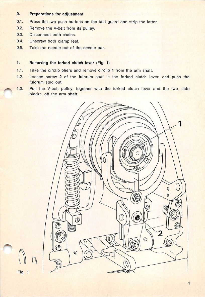
1.
Removing
Take
1.1.
1.2.
Loosen
fulcrum
1.3. Pull
the
blocks,
for
adjustment
the
two
push
the
V-belt from its puiiey.
both
chains.
both
ciamp
the
needle
outofthe
the
forked
the
circlip
pliers
screw
2 of
stud
out.
V-beit pulley,
off
the
arm
buttonsonthe
feet.
needle
clutdi
lever
and
remove
the
fulcrum
together
shaft.
belt
guard
bar.
(Fig.
1)
circiip1from
studinthe
with
the
and
forked
the
forked
strip
arm
clutch
the
clutch
lever
iatter.
shaft.
lever,
and
and
the
push
two
the
slide
Fig.
0
w
1
Page 4
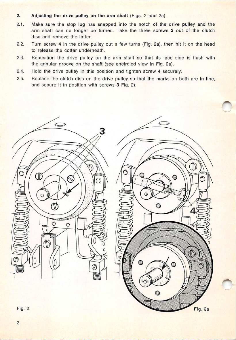
2.
Adjusting
2.1.
Make
arm
disc
2.2.
Turn
to
2.3.
Reposition
the
2.4. Hold
2.5.
Replace
and
sure
shaft
and
screw
release
annular
the
secure
the
drive
the
stop
can
no
remove
4 In
the
cotter
the
drive
grooveonthe
drive
pulley in
the
clutch
it In
pulleyonthe
lug
has
snapped
longerbeturned.
the
latter.
the
drive
pulley
underneath.
pulleyonthe
shaft
this
position
disconthe
position
with
arm
out
(see
drive
screws
shaft
(Figs.2and
Into
the
Take
the
a few
turns
arm
shaftsothat
encircled
and
tighten
pulleysothat
3 Fig. 2).
2a)
notchofthe
three
screws3outofthe
(Fig. 2a),
view
its
in Fig.
then
face
2a).
screw4securely.
the
marksonboth
drive
pulley
hit it on
sideisflush
are
and
the
in line,
the
clutch
head
with
o
o
o
Qb
©
©
Page 5
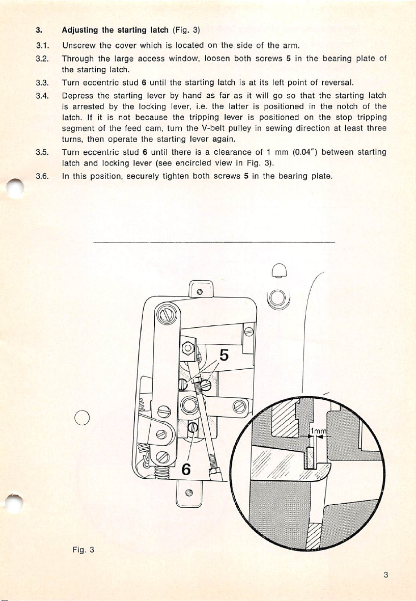
3.
3.1.
3.2.
3.3.
3.4.
3.5.
3.6.
Adjusting
Unscrew
Through
the
Turn
Depress
is
latch,
starting
eccentric
arrested
if it is
the
the
the
latch.
the
by
segmentofthe
turns,
then
operate
Turn
eccentric
iatch
and
locking
in
this
position,
starting
cover
whichislocated
large
access
stud
6 until
starting
leverbyhandasfarasit will gosothat
the
locking lever, i.e.
not
because
feed
cam,
the
stud
6 until
lever
securely
iatch
starting
(see
tighten
(Fig. 3)
window,
the
starting
the
turn
the
there
encircled
on
ioosen
tripping
V-belt
lever
is a
both
the
sideofthe
both
iatchisat
the
iatterispositionedinthe
ieverispositioned
screws
its ieft
arm.
5 in
pointofreversai.
pulleyinsewing
again.
clearance
viewinFig.
screws
of 1 mm (0.04")
3).
5 in
the
bearing
the
bearing
the
starting
notchofthe
on
the
stop
directionatleast
between
plate.
piate
latch
tripping
three
starting
of
O
Fig. 3
Page 6
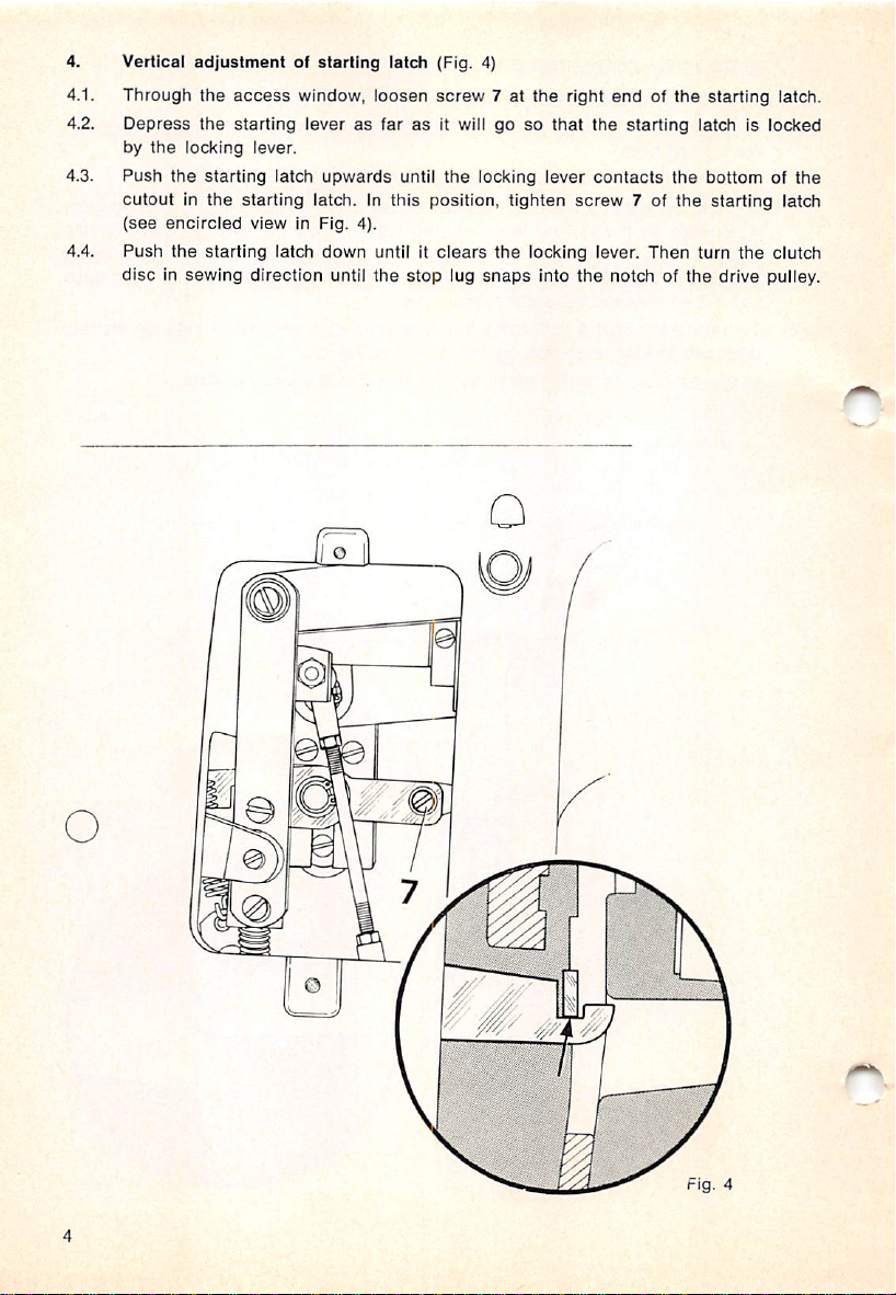
4. Vertical
Through
4.1.
4.2.
Depress
by
4.3.
Push
cutoutinthe
(see
4.4.
Push
adjustmentofstarting
the
access
the
starting leverasfarasIt will gosothat
the
locking lever.
the
starting
starting latch. In this position,
encircled
the
view
starting latch
disc in sewing direction until the
window,
latch
in Fig. 4).
upwards
down
latcfi (Fig. 4)
loosen
screw
until
the
until it
clears
stop
7 at
locking lever
tighten
the
lug
snaps
the
right
endofthe
the
contacts
screw
locking lever.
starting
7 of
latch is locked
the
the
Then
turn
starting
bottom of
starting latch
the
latch.
clutch
into the notch of the drive pulley.
the
O
Fig.
4
Page 7
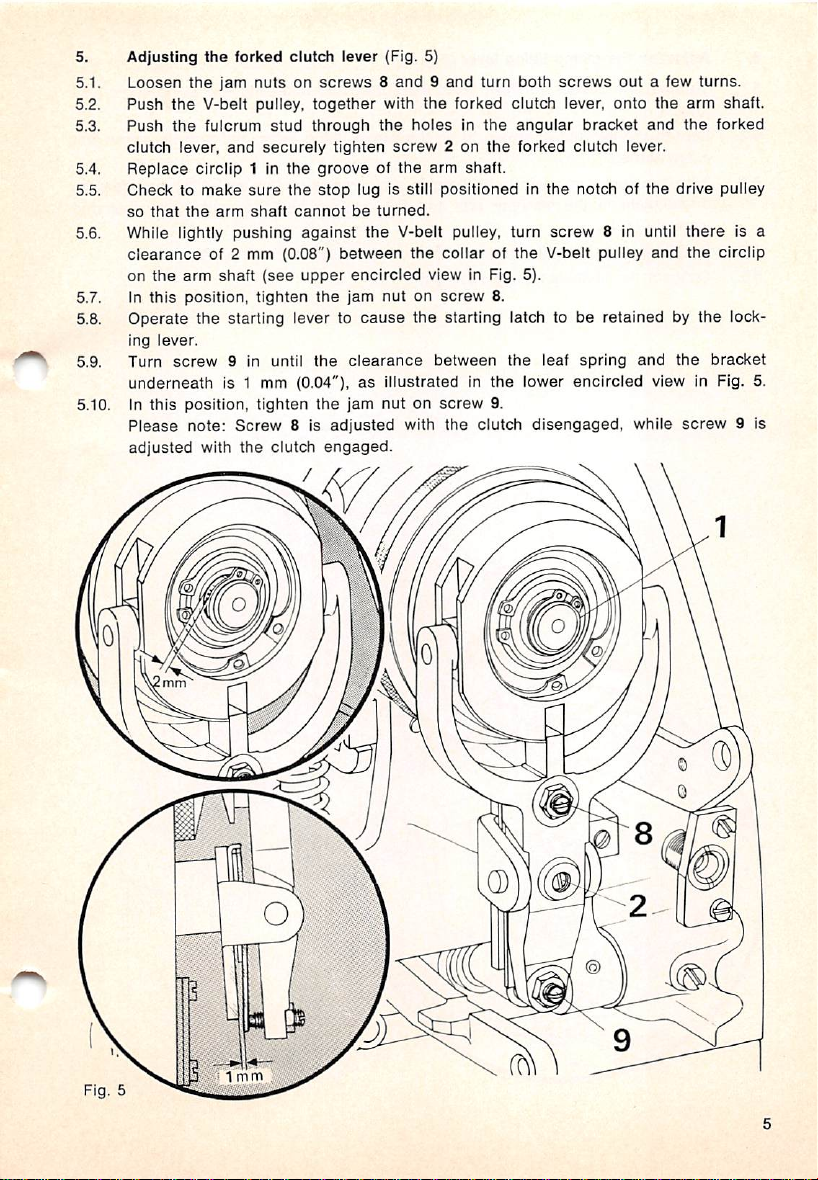
5.
Adjusting
5.1.
Loosen
5.2.
Push
Push
5.3.
clutch
Replace
5.4.
Checktomake
5.5.
so
5.6.
While lightly pushing against the V-belt pulley, turn
clearance
on
In
5.7.
5.8.
Operate the starting lever to
ing
5.9.
Turn
the
the
lever,
that
the
this
lever.
screw
the
forked clutch lever (Fig. 5)
the
jam
nutsonscrews8and9and
V-belt pulley,
fulcrum
and
clrcllp 1 in
sure
the
arm
shaft
stud
securely
the
the
cannot
together
through
of 2 mm (0.08")
arm
shaft
(see
upper
position,
tighten
9 in until
the
the
with
the
tighten
screw2on
grooveofthe
stop
lug is still
be
turned.
between
encircled
jam
nutonscrew
cause
clearance
turn
both
the
forked clutch lever,
holesInthe
the
screws
angular
forked
brad<et
clutch
out
onto
lever.
arm shaft.
positionedinthe
the
collarofthe
notch of
screw
8 in until
V-belt pulley
view in Fig. 5).
8.
the starting latch to be retained by the lock
between
the
leaf
spring
and
underneath is 1 mm (0.04"), as illustrated in the lower encircled view in Fig. 5.
In this position, tighten
5.10.
Please
adjusted
note:
with
Screw
the
8 is
clutch
the
adjusted
engaged.
/
jam nut on
with
screw
the
9.
clutch
disengaged,
while
a few
the
arm shaft.
and
the
the
drive pulley
there
and
the
the
screw
turns.
forked
Is a
clrcllp
bracket
9 is
Page 8
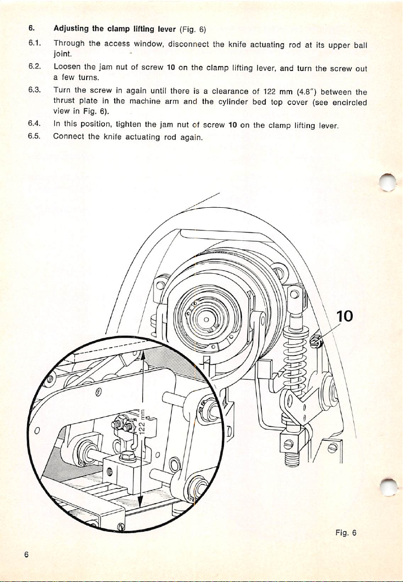
6. Adjusting the clamp lifting lever (Fig. 6)
6.1.
Through
joint.
6.2. Loosen the jam nut of screw 10 on the clamp
a
6.3.
Turn
the access
few
turns.
the screw in again
window,
until
disconnect the
knife
lifting
there is a clearance of
actuating rod at its upper
lever, and turn the screw out
122mm(4.8")
thrust plateInthe machine arm and the cylinder bed top cover (see encircled
view in Fig. 6).
6.4.
In
this
position,
6.5. Connect the knife actuating rod again.
tighten
the
jam
nut of screw 10 on the
clamp
lifting
o
between
lever.
ball
the
Fig.
6
Page 9
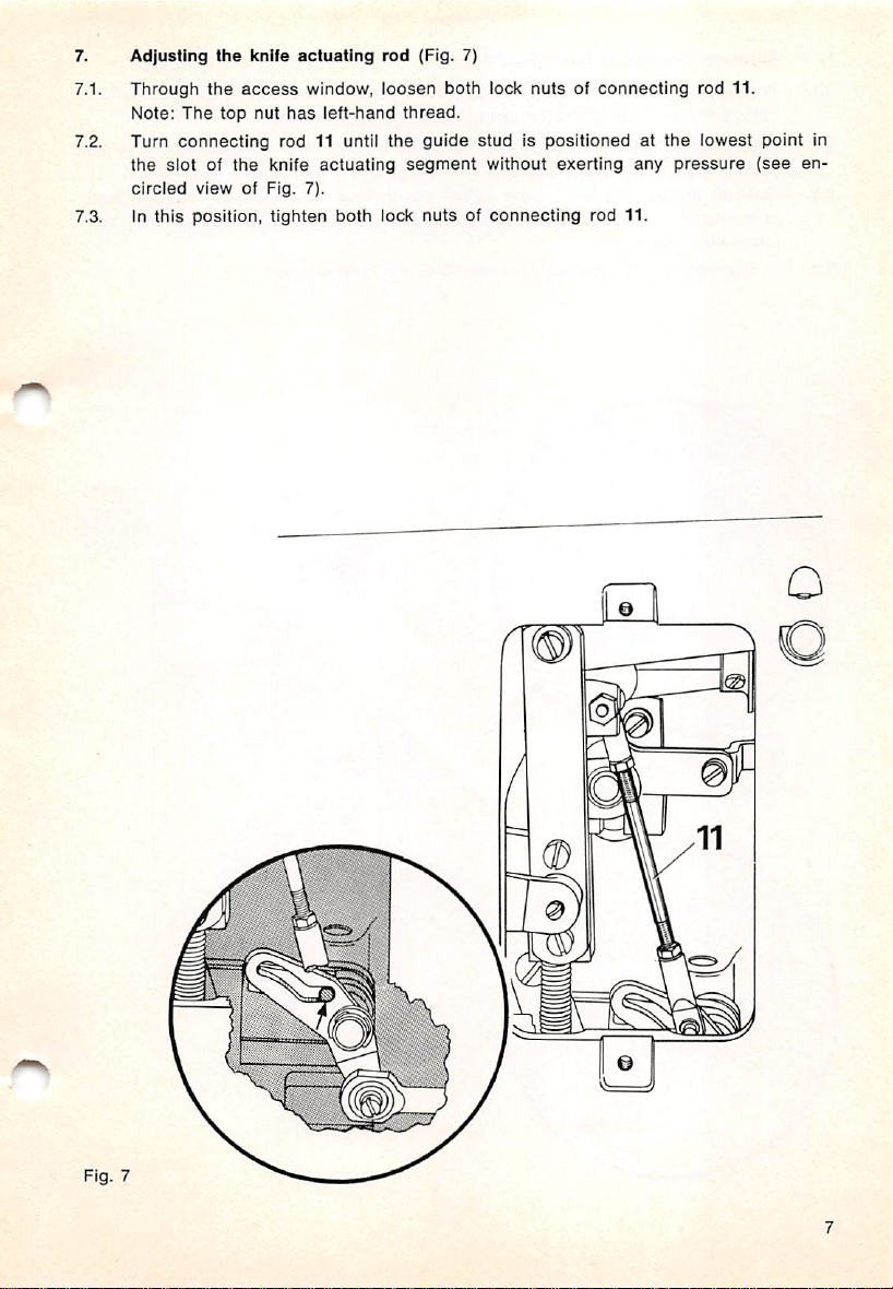
7.
Adjusting
Through
7.1.
Note:
7.2. Turn
the
circled
7.3. In
the
knife
actuating
the
access
window,
The
top nut
connecting
slot of
view
this
position, tighten both lock
has
rod 11 until
the
knife
of Fig. 7).
left-hand
actuating
rod
(Fig. 7)
loosen
both
thread.
the
guide
segment
nutsofconnecting
lock
nutsofconnecting
studispositionedatthe
without exerting
any
rod 11.
rod 11.
lowest point in
pressure
(see
en
O
Fig.
0)
7
Page 10
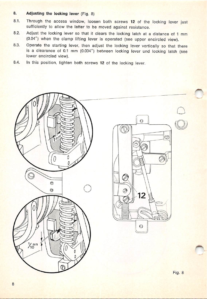
8.
Adjusting the locking lever (Fig. 8)
8.1.
Through
sufficiently to allow the latter to be moved against resistance.
8.2.
Adjust the locking lever so that it clears the locking latch at a distance of 1 mm
(0.04")
8.3.
Operate the starting lever, then adjust the locking lever vertically so that there
Is a clearance of
lower
8.4.
In this position, tighten both screws 12 of the locking lever.
the access
when
encircled
the
clamp
0.1
view).
window,
lifting
mm
(0.004")
loosen
lever
both
screws 12 of the
Is operated (see upper encircled
between
locking
lever und
locking
locking
lever
just
view).
latch (see
o
Q
m
Fig.
8
Page 11
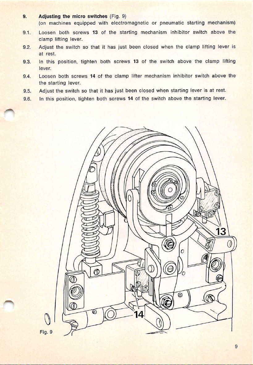
9.
Adjusting
(on
9.1.
Loosen
clamp
9.2. Adjust
at
9.3. In
lever.
9.4.
Loosen
the
machines
both
lifting
the
rest.
this
position,
both
starting
the
micro
equipped
screws
lever.
switchsothatithas
tighten
screws
lever.
9.5. Adjust the switch so
9.6. In
this
position, tighten
switches
with
13 of
both
14 of
the
thatithas
both
(Fig. 9)
electromagnetic
the
starting
just
been
screws
screws
clamp
just
13 of
lifter
been
14 of
or
pneumatic
mechanism
closed
the
mechanism
closed
the
switch
inhibitor
when
the
switch
above
inhibitor
when starting lever is at rest.
above
the
starting
switch
clamp
lifting lever is
the
switch
starting lever.
mechanism)
above
clamp
lifting
above
the
the
Fig.
Q
6)
w
9
Page 12
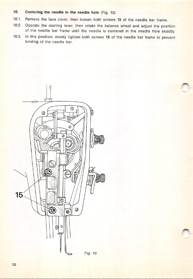
10. Centering the needle in the needle hole (Fig. 10)
10.1. Remove
10.2.
Operate the starting lever, then rotate the balance wheel and adjust the position
the
face
cover, then
loosen
both
screws
15 of
the
needle
of the needle bar frame until the needle Is centered in the needle hole exactly.
10.3.Inthis position,
bindingofthe
evenly
needle
tighten both screws 15 of the needle bar frame to prevent
bar.
bar
frame.
Fig. 10
10
Page 13
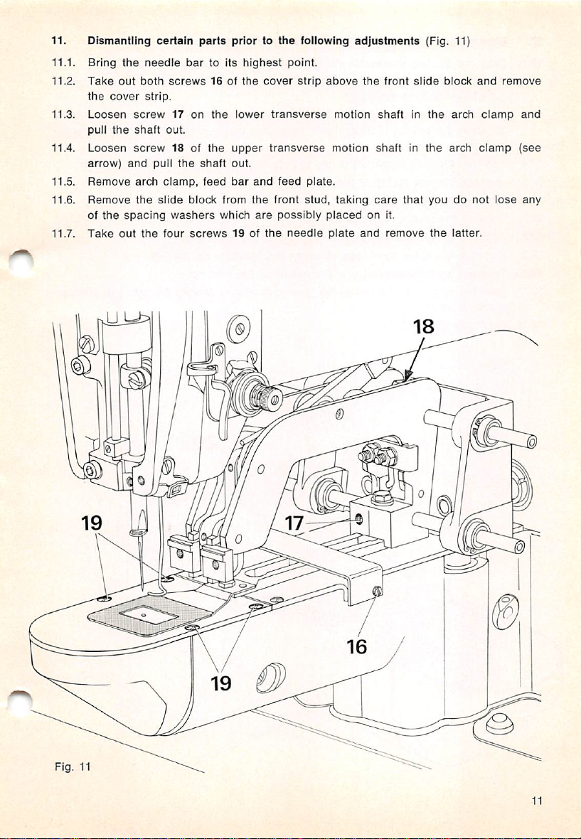
11. Dismantling
11.1. Bring
11.2.
11.3.
11.4.
11.5.
11.6.
11.7.
Take
the
cover
Loosen
pull
the
Loosen
arrow)
Remove
Remove
of
the
Take
the
out
screw
shaft
screw
and
arch
the
spacing
out
certain
needle
both
strip.
pull
slide
the
screws
17
out.
18 of
the
clamp,
washers
four
parts
bar
on
shaft
feed
block
screws
to Its
16 of
the
the
from
which
prior to
highest
the
lower
upper
out.
bar
and
the
are
19 of
the
point.
cover
transverse
transverse
feed
front
possibly
the
needle
following
strip
above
plate.
stud,
placedonit.
plate
adjustments
motion
motion
taking
and
the
front
shaftInthe
shaftinthe
care
remove
(Fig. 11]
slide
that
block
and
arch
arch
youdonot
the
latter.
clamp
clamp
lose
remove
and
(see
any
Fig.
U
17
19
11
11
Page 14

12. Dismantling certain parts prior to the following adjustments (Fig. 12)
12.1.
Take
out
the
two
screws
20
which
are
locatedinthe
trunnion
block.
12.2. Pull the trunnion block forward as farasit will go, then remove it by pulling it
outofthe
12.3. Remove
stripping
washers.
12.4.
Take
12.5.
Unscrew
12.6.
Unscrew
12.7.
Take
12.8.
Take
12.9.
Unscrew
Take
12.10.
12.11. Turn
clockwise,
12.12.
Then
out
off
the
out
the
strip
machine
slide
the
the
the
the
the
shuttle
the
the
eccentric
and
the
sideways.
block
guide
trunnion block. Again
four
screws
leaf
springofthe
cylinder
shuttle
roller
hexagon
and
race
the
lever
bed
screwinthe
bushinginthe
pull it
out.
feed
cam.
together
21 of
cap.
cover.
bobbin
located
with
take
the
cylinder
cylinder
case
under
middleofthe
feed
the
slide
care
bed
bed
cap.
outofthe
the
bedplateonthe
cam
slightly
block which
that
you do
top
shuttle
feed
cover
race.
cam.
toward
and
dot
the
left.
are
lose
strip
left,
exposed
any
the
latter.
i.e.
counter
aftei
spacing
12
Page 15

13.
13.1.
13.2.
13.3.
13.4.
13.5. In
13.6. In
13.7.
Setting
Turn
hititon
Operate
driver
Then
the
Loosen
clamp
screw
the
Replace
the
the
is
exactlyinthe
this
position,
race
lengthwiseofthe
between
this
the
position,
shaft
take
shuttletothe
screw
22 of
23 on
the
right-hand
head
to
release
shuttleInits
starting
middleofthe
move
race.
lever
the
cylinder
pointofthe
securely
bearinginposition.
the
shuttle
shuttle
tighten
out
needle
the
the
and
shuttle
of its
(Fig. 13)
shuttle
sideofthe
cotter
turn
the
clearance
driver
bed
and
screw
race
driver
underneath.
V-belt
until
the
23 of
again.
and
cylinder
pulley
cutofthe
shaft
there
needle
the
pull
needle.
bearing
is a
clearance
(see
cotter
the
latter
bed
until
the
together
encircled
which
off its
shaft.
out
a few
turns,
pointofthe
with
the
of 0.1 mm (0.004")
view
of Fig. 13).
secures
the
then
shuttle
shuttle
shuttle
Fig.
10mm
13
13
Page 16

14.
Setting the shuttle driver
14.1.
Loosen
14.2.
Loosen
Turn the V-belt pulley to bring the
14.3.
Pull the shuttle driver shaft forward as far as it
14.4.
14.5.
Turn the
both
both
rear
screws
screws
collar so that
shaft
24inthe
25 in
the
longitudinally (Fig. 14)
front
collarofthe
rear
collarofthe
needle
to its highest point.
one
of its
screws
shuttle
driver
shaft.
shuttle
driver
shaft.
wili
go.
points to the right —as
above —and the other faces upwards. Then push the collar up against the shuttle
driver
shaft
bearing
14.6.
Push
the
shuttle
(0.05")
between the rear collar and the bearing.
14.7.
In
this
position,
wards and the
shaft
bearing.
14.8.
Loosen
screw 25 in the rear collar tightened
against the shuttle driver shaft bearing, while
and
tighten
the
accessible
driver
shaft
toward
the
turn
the
front
collarsothat
other
to the upper left, and push it up against the shuttle driver
Tighten
the
lower
screw.
back
screw
25.
until
there
Is a
clearanceof1.3
one
of its
screws
previously,
lightly
and press this collar up
pushing against the front end
24
of the shaft. In this way, a clearance of 1.3 mm (0.05") is provided between the
wall of the arm standard and the spur gear on the shuttle driver shaft (see en
circled
view of Fig. 14).
14.9.
In this position, securely tighten both
14.10.
Then
securely
tighten
Please note: The shuttle
any
end
play.
the
second
driver
screw
shaft
screws
24 on
should
25 on the rear collar.
the
front
collar.
turn
lightly,
however
seen
faces
without
from
mm
down
having
Fig. 14
14
Page 17

15.
Adjusting
15.1.
Prize
15.2. Bring
15.3.
Place
the
the
circliponthe
the
needle
the
shuttle
shuttle
driver
bar
to its lowest point.
driver
shuttle
on its
(Fig. 15)
driver
shaft
and
shaft
push
forward.
it up
against
the
circlip.
15.4. Tap both parts - the shuttle driver and the circlip —back until, when you turn the
shuttle
needleaspossible,
15.5. In
this
driver, its finger with
without
position, lightly
tighten
the
needle
deflecting
the
clamp
deflecting
it.
screwofthe
surface
shuttle
passesasclosetothe
driver.
Fig.
15
15
Page 18

16. Adjusting the radial play of the shuttle driver (Fig. 16)
16.1.
Unscrew both nuts of the bobbin winder on the back of the machine, and strip
the
bobbin
winder.
16.2. Take out the eight screws of the bearing plate underneath and remove the plate.
16.3.
Loosen the three screws 27 in the eccentric bearing bushing exposed now.
16.4.
Turn
the
longer
eccentric
has
any radial play, but light running of the machine is still ensured.
stud
with
the
aid
of a
screwdriver
until
the
shuttle
driver
no
16.5. Evenlytighten all three screws 27 of the eccentric bearing bushing.
Fig. 16
17.
Timing
the shuttle
17.1.
Check to make sure that the first screw (in sewing direction) of all parts located
on the arm shaft, e.g.
in the groove, and that all
17.2.
Loosen the clamp screw of the shuttle driver just sufficiently to allow the latter
to be
turned
17.3.
Replace
17.4. Bring the
the
needle
driver
motion
spur
gear,
screws
on its
shaft
against
shuttleinthe
bar to its lowest point.
shuttle
and adjusting the needle rise
eccentric
are
resistance.
race.
and worm. Is positioned on the flat or
securely tightened.
(Fig.
17)
17.5. Set the machine for a needle bar rise of 2.4 mm (0.09"). Turn the shuttle and the
shuttle driver so that the shuttle point is exactly behind the needle.
17.6.
Rotate the
again contacts the needle bar
be
positioned
16
V-belt
pulley backwards until the C-clamp screwed to the needle bar
frame.Inthis position, the shuttle point must again
exactly
behind
the needle (see encircled
viewinFig.
17).
Page 19

17.7. If
17.8.
17.9. In
the
pointofthe
and
loosen
accessible
tobeturned
Turn
the
until
the
needle
bar
then
backwards.
this
position,
the
latter
the
through
against
belt
sprocket
shuttle
contacts
contacts
shuttleisnot
three
screws
the
access
resistance.
on
point is
the
securely
its
bearingonthe
the
exactly
needle
tighten
17.10. Remove the C-cIamp from the
tighten
the
clamp
screwofthe
17.11.
Loosen
17.12.
Replace
amountofplay
17.13.
Securely
both
screwsofthe
the
shuttle
tighten
in its
between
both
shuttle
race
shuttle
screwsofthe
exactly
28 of
window)
arm
bar
screw
needle
shuttle
and
and
the
shaft
behind
frame
right.
race.
adjust
shuttle
shuttle
behind
the
belt
sprod<et
just
sufficientlytoallow
just
slightly
the
needle
after
turning
28 on
the
belt
bar,
take
the shuttle out of its race, and
driver
securely.
the
lattersothat
driverinboth
race.
needle,
on
the
and
when
the
sprocket,
remove
arm
shaft
the
belt
repeat
this
the
C-clamponthe
V-belt pulley
making
thereisthe
ultimate
positions.
the
C-olamp
(which
sprocket
adjustment
forwards,
sure
are
that
same
O
Fig.
17
17
Page 20

18.
Setting the needle bar at the correct height (Fig. 18)
18.1.
Turn the
site
18.2.
Loosen clamp screw 29 on the needle bar connecting stud.
18.3.
Move
V-belt
pulley in sewing direction until the shuttle point is exactly oppo
the
center
lineofthe
needle.
the needle bar up or down until there is a clearance of 1.5 mm
between the lower edge of the shuttle point and the top of the needle eye (see
encircled
18.4.
In this position, securely tighten clamp screw 29 on the needle bar connecting
view of Fig. 18).
stud, making sure the thread guide screw on the needle bar points toward the
rear.
18.5.
Screw
on the shuttle
18.6.
Push the starting latch out of the locking lever and turn the clutch disc in sewing
race
cover, making
sureItdoes
not lose its resilience.
direction until the stop lug has snapped into the notch of the drive
(0.06")
pulley.
—i.o
mm
Fig.
18
18
Page 21

19.
Adjusting
Loosen
19.1.
the
19.2.
Loosen
tobemoved
19.3.
Operate
forward
19.4. Adjust
53 mm (2.09")
and
the
clamp
left,
and
screw30just
the
pointofreversal.Inthis
the
the
tip of
38 mm (1.5")
knife
(see
encircled
this
19.5. In
position,
puller. Make
positionedasclosetothe
contacting
It.
bobbin
screw
lightly
against
clamp
bobbin
between
the
between
sure
thread
puller
31 of
the
tighten
the
sufficientlytoallow
resistance,
lifting
levertobring
thread
puller
the
left
bobbin
thread
the
left
view
of Fig. 19).
securely
as
you tighten
tighten
shuttle
and
the
movable
needle
clamp
position,
edgeofthe
puller,inaddition,
edge
screw
and
the
of this hole
screw
the
race
thread
the
knife
block
knife so
30 of
screw
as
again.
right
possible
catcher,
knife
and
the
screwhole
there
the
that
knife (Fig. 19)
swing
the
latter
and
the
bobbin
clamp
that
and
knife
the
bobbin
thread
lifting lever.
there
shouldbea
the
and
bobbin
is a
on
the
cutting
the
thread
thread
pullertotheir
clearance
needle
clearance
edgeofthe
bobbin
vertically, without actually
toward
puller
of
plate
of
thread
puller is
Fig. 19
o
38
mm
53
mm
19
Page 22

20. Mounting
20.1.
Loosen
cam.
20.2. Turn the eccentric bushing of the feed cam so that its lobe points upwards,
toward
20.3.
fvlount
the
cam.
20.4. Insert the pin of the
in
20.5.
Turn
spur
20.6. In this position,
the
feed
cam
(Fig. 20)
screws
Set
the
the
all
tripping
feed
these
32, 33, 34, 35
screwsinthe
segment
camsothat
and36and
middle of
on
the
the
cutoutinits
rim of
right-hand roller lever is positioned in
cap
the
hexagon
the
gears,
washer
srewbyhandasfarasit will go.
eccentric
but
bushing
the
machine
securely
tighten
into the hole of the
clockwise
still
turns
the
hexagon
their
the
until
easily.
the
three
slots
cam.
rim isonthe
the
channelonthe
there
is no
screwofthe
alien
screws
and
tighten
eccentric
backlash
37 of
them again.
left
and
the
upper
bushing and turn
between
feed
cam.
the
feed
i.e.
roller
sideofthe
both
20.7. Mount the roller lever on the left-hand feed motion segment, and adjust the latter
so
that
the
20.8.
Securely
rollerispositionedinthe
tighten
the
two
screwsofthe
channelofthe
roller
lever.
cam.
of
Fig.
20
20
Page 23

21.
Timing
the
feed
motion
(Fig. 21)
21.1.
Operate
and
motion
point. (Only
21.2.
If adjustment is required, loosen the three
the
21.3.
Securely
the
the
feed
before,
camonits
tighten all
starting lever
motion
leversinthe
and
the
one
lever moves at
shaft
accordingly.
three
and
second
screws
turn
cylinder
half
any
37 of
the
V-belt pulley while watching
bed.
Each
lever
after,
the
needle
bar
given time).
the
feed cam.
screws
37 in the feed cam and turn
has
should
reached
the
make
Its
needle
half its
highest
Fig.
21
21
Page 24

22. Adjusting
the
stop
tripping
segment
(Fig. 22)
22.1. Turn the V-belt pulley in sewing direction until the machine has completed Its
sewing
15 mm (0.6")
22.2. if it is not, check to
22.3.
Operate
22.4. Loosen
22.5. If the machine stops too late,
it
22.6. Check again to
(0.6")
ment
cycle
and
above
stopped.
the
The
take-up
bottom
of Its stroke.
see
whether the machine
lever
should
has
the starting lever and turn the V-belt pulley backwards
the
three
screws
33 of
the
segmentonthe
set
the segment earlier, if it stops too early,
later.
Then
securely
above the
until
this
tighten
the
three
screws
see
if the machine stops with the take-up lever exactly 15 mm
bottom
condition
of its stroke. If it does not, repeat the foregoing adjust
is
met.
33.
now be
stopped
feed cam.
positioned
about
too early or too late.
about
two turns.
set
22.7. Turn the clutch disc in sewing direction until the machine has completed its
sewing cycle and stopped. The machine Is now in its starting position.
Fig.
22
22
Page 25

23.
Adjusting
Checktomake
23.1.
of
this
23.2.
Setaclearance
catcher
23.3. In
actuating
the
position,
this
the
needle
crank
position,
rod.
thread
catcher
sure
the
machine
thread
catcherisat
loosen
both
of 0.3 mm (0.01")
(see
encircled
securely
crank
screws
view
tighten
(Fig. 23}
is in its
the
highest
38 of
the
between
of Fig, 23),
first
the
starting
two-part
the
front,
position
point
thread
cylinder
then
of its
bed
the
and
tripping
catcher
wall
rear
the
and
screw
tripping
segment.
actuating
the
38ofthe
stud
In
rod.
thread
Page 26

24.
24.1.
Adjusting
Operate
the
the
its lowest point. During this
ping
stud
must
24.2. Loosen
thread
24.3.
Press
as
bed,
24.4. Swing
and,
When
starting
24.5. Adjust
bobbin
24.6. Loosen
24.7. Turn
thread
(see
24.8.
Press
clamp
catchertobe
the
thread
It will go, i.e. until
and
hold
the
needle
in this position,
you
release
position.
the
thread
thread
the
screw
catcher
encircled
the
starting
V-belt pulley
needle
thread
starting lever
catcher
and
turn
(Fig. 24)
the
V-belt pulley to bring
phaseofthe
have
screw
catcher
it in
cleared
31 of
turned
this
thread
securely
the
catcher
the
tripping
the
needle
thread
on its
shaft
against
actuating
the
thread
position.
catcher
actuating
catcher
inwards
tighten
rod in
clamp
rod,
the
verticallysothatitpasses
puller, i.e. without touching any of
lock nut of
39 until
and
view at right). In
backwards
there
the
latch
screw
is a
needle
outofthe
until
the
39 on
clearance
when
this
machine
the
left
the
position,
cutoutofthe
machine
segment.
the
crank
until it
of 4 mm (0.16")
thread
cycle,
catcher
resistance.
cylinder
just
bed
contacts
contacts
screw31(see
thread
catcher
these
sideofthe
catcher
tighten
the
locking iever,
the
thread
sufficiently to allow
toward
the wall of
the
encircled
should
freely
between
parts.
cylinder arm.
between
is in its
lock
nutonscrew
is in its starting position.
the
the
needle
starting
and
needle
the
bar
catcher
trip
the
leftasfar
the
cylinder
just
lightly
view at left).
return
to its
knife
and
tip of
the
position
39,
rotate
the
to
Fig. 24
24
Page 27

25.
Timing
Operate
25.1.
25.2.
Then
exactly
25.3. in
and
25.4. Now
lever
25.5. In
25.6.
Turn
this
the
25.7.
Turn
notchofthe
rotate
this
move
move
contacts
this
the
latter
shuttle
the
the
thread
the
starting
the
behind
the
position,
the
segment
the
tripping
the
position,
V-belt
phase,
pointisexactly
clutch
drive pulley.
catcher
V-belt
loosen
motion
lever
and
puiieyinsewing
rising
needie.
both
ali
the
segment
inclined
tighten
puiiey
the
surfaceofthe
both
backwards
needle
opposite
discinsewing
The
(Fig. 25)
turn
the
V-beit
direction
screws
32ofthe
waytothe
toward
screws
32 of
one
thread
catcher
the
rising
direction
machineisthus
ieft.
the
tripping
half
untii
puiley
until
thread
right untii
the
thread
turn,
should
needle.
the
in its
backwards
the
pointofthe
catcher
the
studofthe
segment.
catcher
then
slowly
begintomove
stop
lug
has
starting
one
turn.
tripping
tripping
forwards.
forward
snapped
position
shuttle
segment
actuating
segment.
During
when
into
again.
is
the
Fig. 25
25
Page 28

26.
Adjusting
26.1.
Loosen both
sideofthe
26.2.
Set
the needle hole and the cutting
26.3.
In this position, tighten both
26.4.
Replace and screw on the needle plate.
26.5.
To make a cutting test, pull two threads through the needle hole and operate the
lifting
26.6.
If they
its cutting
to
after the
26.7.
Screw on the cylinder bed lop cover, insert the trunnion block into the bearing
bushing of the machine and push it toward the rear as far as it
the
stationary
screws
needle
the knife so that
knife (Fig. 26)
40 of
plate.
there
the
stationary
is a
clearance
edge
screwsofthe
knife which
are
locatedonthe
of 1 mm (0.04") between the
of the knife
(see
encircled view of Fig. 26).
knife again.
lever by hand. As you do this, both threads should be trimmed perfectly.
are
not, remove the needle plate and adjust the knife so that the left
edge
—as
seen
from the front —is a little higher than the right. This is
ensure
a perfect shearing action between the movable and the stationary knife
needle
plate
has
been
screwed on again.
will
two slide blocks on their studs, making sure that their smooth surfaces are facing
upwards. Take
care
that the spacing washers are replaced, if any. Turn the rear
slide block on its stud so that its long side faces toward the right.
26.8.
Place
the
slide
block
guide
over
the
rear
slide
block
and
screw
it to
block with
26.9.
Replace the arch clamp, together with the feed bar and the feed plate, so that the
front
slide
the
block
aid of
enters
the
two
the
pan-head
channelinthe
screws.
feed
bar.
Push
both
transverse
through the holes in the trunnion block and the arch clamp so that their
protrude
equally on both
sides.
Then
tighten both
transverse
shaft
under
edge
end
go. Place the
the
trunnion
shafts
screws.
of
of
ends
Fig.
26
26
Page 29

28.
28.1.
28.2.
28.3. In
28.4. if
Setting
Open
the
cylinder
Loosen
as
farasthey
this
the
suitable
the
the
two
both
position,
largest
limiting
machine
covers
bed.
hexagon
will
tighten
tack
brackets
for Its
iargest
which
are
nuts43which
go.
both
nuts43securely.
shouldbebigger
under
tack
size
locatedonthe
are
now
than
both
nuts.
(Fig. 28)
bedplatetothe
exposed
the
cutoutofthe
and
push
clamp
right
them
and
feet,
left of
inwards
place
28
Page 30

29.
Centering
29.1.
Loosen clamp screw 44 in the left
blocktobe
29.2.
Also loosen clamp
trunnion
Operate the starting lever by hand. Then turn the V-bell pulley in sewing direction,
29.3.
the
tack
moved
blocktobe
designinthe
crosswise
screw
45 in the right crank just sufficiently to allow
moved
lenghtwise
cutoutofthe
crank
against
clamp
feet (Fig. 29)
just sufficiently to allow the trunnion
resistance.
against
resistance.
while simultaneously adjusting the position of the arch clamp until the needle at
the extreme right and left of the tack design clears both clamp feet at the same
distance.
Tighten clamp
29.4.
Continue turning the V-belt pulley In sewing direction until the machine starts
29.5.
feeding
29.6.
Adjust the position of the arch clamp until the needle while stitching the near
and far
cutout
29.7.
Tighten clamp screw 45 of the right clamp.
29.8.
Continue turning the V-belt pulley until the machine has completed its sewing
cycle and stopped. Then rotate the
screw
lengthwiseofthe
side
of the tack design
at
the
same
distance.
44 of the left crank.
cylinder
bed.
clears
clutch
the
near
disc
and far
until
edge
of the clamp feet
the stop lug has snapped
into the notch of the drive pulley, and the machine is in its starting position again.
the
29
Page 31

30. Timing the tension
30.1.
Operate the starting lever by hand, and turn the
until
the
take-up
30.2.
Loosen both screws 36 of the tension release tripping segment on the feed cam
and push them down as far as they will go.
30.3.
Then push the tension release tripping segment back as far as it
it
contacts
the feeler lever. In this position, tighten both
release
lever Is at its
mechanism (Fig. 30)
lowest
point.
V-belt
pulley in sewing direction
will
screws
36.
go, i.e.
until
30.4. To check this adjustment, turn the V-belt pulley backwards until the needle bar is
at its lowest point. In this position,
the
lower
tension
must be
released.
30.5. Then again bring the machine to its starting position.
Fig.
30
30
Page 32

31.
31.1.
31.2.
31.3.
31.4.
31.5.
31.6.
31.7.
Adjusting
Operate
direction
In
Turn
slack
The
the
downwards
In
Turn
this
screw
thread
thread
tension
this
the
the
until
position,
position,
nowbefully
46
and
the
Then
bring
the
tension
starting
screw46of
loosen
46 until
regulator
tension
release
slightly.
tighten
V-belt
pulleyinsewing
activated
actuating
the
machine
release
lever by
the
the
thread
and
should
lever
the
and
lever.
the
lock
both
still
toward
lock
there
to its
iever
(Fig. 31)
hand
and
tension
release
nutofscrew
check
spring
tension
haveasmall
the
right,
nutofscrew
direction
must
starting
position
slightly
discs
be a
46.
is in
amount
the
46.
a few
small
rotate
the
V-belt pulley in sewing
leverisaccessible.
line
with
the
are
separated
of play, i.e.
thread
check
turns.
The
amountofplay
again.
bottom
(see
spring
thread
edgeofthe
encircled
when
should
tension
between
you
view).
press
move
must
screw
Fig.
31
31
Page 33

32.
Timing
32.1.
Checktomake
screwsofthe
chine
32.2. Adjust
between
the
32.3. In
32.4. Briefiy
32.5. If
32.6.
32.7.
this
front
the
Make
Operate
As you
stitch.
32.8. If
32.9.
32.10.
32.11.
the
outer
Set
Repeat
first
Turn
low
the
32.12. If
the
inner
32.13.
Set
35
again.
32.14. Bring
the
motor
pole-changing
base).
the
switch vertically so
the
horizontal
actuating
endofthe
motor
sure
switch-over
the
stitch.
the
speed.
machine
plungerofthe
position,
switchonthe
tighten
machine,
rotates
the
V-beltisstill
the
starting
do
this,
the
motor
switches
switch-over tripping
this
adjustment
V-belt pulley in
Continue
makes
motor
switches
switch-over
the
inner
switch-over tripping
the
machine
speed
changes
sure
the
machine
actuating
switch.
the
three
motor
and
the
counter-clockwise,
removed,
leverbyhand,
motor
shouid
over
too
tripping
segment
segment
until
sewing
turning
another
tripping
to its
the
four
over
too
segmentonthe
starting
(Fig. 32)
is in its
switch (on
that
there
lever
screwsofthe
ched<
motor
should
exchange
and
and
switch
earlyortoo
on
the
earlierorlater,
the
motor
direction
V-belt pulley. As
stitches
earlyortoo
segment
position.
starting
the
right-hand
is a
(see
arrow)
its
directionofrotation.Asseen
turn
switchonthe
turn
the
from low to high
late,
feed
switches
until
beforeitswitches
late,
feed
somewhat
position.
outer
clearanceofabout
inside
the
switch
again.
clockwise.
the
wiresinthe
motor.
V-beit
pulleyinsewing
speed
loosen
both
cam.
then
tighten
from low to
the
motor
youdothis,
high
switches
checktomake
off
loosen
both
cam.
earlier,
Loosen
the
surfaceofthe
4 mm (0.16")
machine
base
from
plug.
direction.
after
the
screws
34 of
screws34again.
speed
after
from
mechanically.
screws
and
35 of
tighten
high
screw
three
ma
and
the
first
the
the
to
sure
the
32
Page 34

Fig.
32
33
Page 35

33.
Adjusting
33.1.
Replace
ciently to allow
33.2. Reposition
reiiably by
in
33.3. in
33.4. Mount
winder
winder.
33.5.iftoo
stop
33.6. Adjust
contact
this
position,
the
spindle,
muchortoo
latch.
the
the
bobbin
winder
the
mounting
the
the
friction wheel when
the
bobbin
bearing
plate
platesothat
with this wheei when
tighten
both
V-beit,
repiace
thread
the
little
threadiswound
studonthe
stop
(Fig. 33)
and
the
winder
plate
the
the
nuts
47.
the
beit
guard,
machine
latchsothat
bobbin winder, tightening
to be moved
the
bobbin
bobbin
bobbin
place
for
bobbin
on
the
bobbin
winderisdisengaged.
the
against
winder
puliey wiii be driven
winderisengaged,
an empty
winding,
bobbin,
winder
bobbinonthe
and
loosen
stops
nuts47just
resistance.
start
screw
when
wound on the bobbin is 1 mm (0.04") below its rim (see encircled view of Fig. 33).
33.7. in this position, tighten
33.8. if the thread on the bobbin has
thread
guideonthe
belt
screw
guard.
48 of
been
the
stop
latch stud.
wound unevenly, adjust the position of the
suffi
but wiil not be
bobbin
the
bobbin
48 of
the
the
thread
34
Page 36

34.
34.1.
34.2.
34.3. In
34.4.
34.5.
34.6.
35.
35.1.
Adjusting
Checktomake
of
Reposition
between
Now
Adjust
at a
circled
Tighten
Adjusting
Loosen
the
thread
the
vertical
the
thread
thread
needle
this
position,
loosen
screw50of
the
thread
distanceofabout
viewatright).
screw50of
the
eye
screw
51 of
sure
and
tighten
wiper
guard
wiper
(Fig. 34)
the
machine
wiper
rodatthe
wiper
rodsothat
thread
wiper
screw
49.
the
thread
wire
verticallysothatitpasses
1 mm (0.04") when
the
thread
wiper
(Fig. 34)
the
lifting
bracketonthe
35.2. Adjust the lifting bracket so that
between
35.3.Inthis
35.4.
Replace
swung
the
position,
the
toward
needle
face
the
tighten
cover
left at
bar
frame
screw
and
the
and
51 of
operate
same
Is in its
needfe-bar
wire.
wiper
wire.
there
the
the
the
moment
starting
there
is a
wire.
the
lifting lever is
vertical
is a
clearanceofabout
bracket.
lifting
bracket
lifting lever to
when
the
0X49
position,
endofthe
and
machine.
clearanceofabout
below
the
operated
thread
wiper
again.
seeifthe
clamp
feet
are
loosen
screw
15 mm (0.6")
needle
(see
rod.
1 mm (0.04")
eye
guard
raised.
49
point
en
is
Fig.
34
mm
35
Page 37

36.
36.1.
36.2.
36.3.
36.4.
36.5.
36.6.
36.7.
36.8.
Final
worksieps
Replace
the
cover
Screwonthe
Screw
on
the
Reconnect
Replace
both
the
threadispulled
about
3 cm (1.2").
Thread
Regulate
the
thread
the
machine
the
loopispassed
Switchonthe
strip
cylinder
cover
chains.
bobbin
through
upper
machine
above
the
bed
cap
and
on
the
sideofthe
case
with a full
the
holeinthe
and
place
material
tensionsothat,
smoothly
and
make
front
slide
the
cap
machine
bobbininthe
position
under
when
around
a few
sewing
block.
retaining
the
the
bobbin
the
spring.
arm.
shuttle,
fingersothat
clamp
thread
shuttle.
and
trimming
making
sure
its
end
feet.
tensionisreleased,
tests.
that
protrudes
the
36
Page 38

37.
Conversiontoother
37.1. Make
sure
the
subclasses
machine
is at its
having
starting
different
gear
position, i.e. at
ratios
the
sewing
cycle
end
position. Take out both screws of the roiler lever located under the bedplate
near
its
left
front
corner.
37.2. Take out the hexagon
washer
underneath.
Then
strip
the
roller
lever.
screw
in the middle of the feed cam and remove the
cap
37.3. Turn the eccentric bushing slightly toward the left, i.e. counter-clockwise, and
37.4.
strip both
Take
of
the
out
machine
the
the
feed
three
and
cam
alien
remove
and
the
bearing
screwsonthe
the
spur
bushing.
gear.
driving
spur
gear
on
the
vertical
shaft
37.5. Insert the spur gear having another gear ratio, and secure it in position with
the
three
alien
screws.
37.6. Now make the adjustment described In Chapters 21 through 32 inclusive.
37
Page 39

38. Explanation of circuit
Original
Switch
position:
Cur
rent
Path
master
*) 6
s
w
switch
diagram
Unit
No. 91-095418-95
a1 off.
Cur
rent
Path
2yl.
Function
a 1
54
b 1
51
56
51
56
52
*) 6 =
s =
w =
3-5
15
15
16
7+8
16
1+2
15
normally
closed
contact
normally
open
contact
change
over
contact
s m 1
o
6 s 1
3
s m 1
0
s m 1
s s 1
^ €
*
Motor
runs
3-5
si
15
Work
Connection
15
s2
$2
16
4
16
Work
Low-speed
After
High-speed
Solenoidisde-energized
Machine
At
4
15
fourthtolast
Low-speed
Machine
Work
slowly
clampisraised
tosinow
clampislowered
sewing
1st
stitch
sewing
remains
stitch
sewing
switches
clampIsraised
SrAfiT
via
r3
on (mechanically)
off mechanically
Nah4n
8»t$hfS9*t9r
38
g^schclttf
Siho/tonj
fuf HOV
Fur
iiOV.
firwAo
*»rjse/i»n7uJVvort
L9iiurig vortAfpnocA Z
t»i
99Z9iehr>9t
ot
Circuit
diagram
No.
91-095418-95
for
the
Pfaff
3337
Page 40

39. Explanation of
Original
position:
master
pneumatic
switch a1 off,
diagram
No. 91-130460-95
compressed
air
on.
a1
V 1
VI
be
V1
be
V2
V5
V4
Switch
Central
Ultimate
Starting
Cur
rent
Path
3-5
position
position
7+8
position
1+2
*)o
s
w
s
8
S m 1
Unit
m 1
V6
m 1 4
V5
V6
V6
Cur
rent
Path
3-5
2yl.
Function
Motorisrunning
Z1-
22
+
Work
clampislowered
Quick
exhausting
Low-speed
After
1st
stitch
High-speed
2
2-
Machine
+
At
Low-speed
Machine
Work
4
21
remains
fourthtolast
switches
clampisslowly
After work
Work
clampisraised
sewing
sewing
sewing
clamp
slowly
action
on
(mechanically)
stitch
of
mechanically
raised
has
risen
quickly
V3
6 =
s =
w =
normally
closed
contact
normally
open
contact
change
over
contact
11
0——10
KlQfrtntr
'MEin
Pneumatic
ffl
*
'C
AM
•M
lifMi
diagram
32IZ})
U(Vil
noO\
ua lUaneiarli^ut^
^ I ytetisi
No. 91-130460-95 for
vW
JH
Z
the
Pfaff 3337
39
Page 41

Contents
0.
Preparations
1.
Removing
2.
Adjusting
3. Adjusting
4. Vertical
5.
Adjusting
6.
Adjusting
7.
Adjusting
8. Adjusting
9.
Adjusting
10.
Centering
11.
Dismantling
12.
Dismantling
13.
Setting
14.
Setting
15.
Adjusting
16.
Adjusting
17. Timing
18. Setting the needle bar at the correct height
19.
Adjusting
20.
Mounting
21.
Timing
22.
Adjusting
23.
Adjusting
24.
Adjusting
25.
Timing
26.
Adjusting
27.
Centering
28.
Setting
for
adjustment
the
forked
clutch
the
drive
pulley on
the
starting
latch
adjustmentofstarting
the
forked
clutch
the
clamp
lifting
the
knife
actuating
the
locking lever
the
micro
switches
the
certain
certain
the
shuttletothe
the
shuttle
the
shuttle
the
radial
the
shuttle
the
bobbin
the
feed
the
feed
the
stop
the
thread
the
needle
the
thread
the
stationary
the
the
machine
needle
clamp
in
the
parts
parts
(continued)
driver
driver
playofthe
driver motion
thread
cam
motion
tripping
catcher
thread
catcher
knife
feetinthe
for its
lever
the
lever
lever
rod
needle
needle
shaft
puller
segment
crank
catcher
motion
largest
arm
shaft
latch
hole
longitudinally
shuttle
driver
and
adjusting
and
the
feed
plate
tack
size
....
....
the
....
movable
cutout
needle
knife .
.
29. Centering the tack design in the cutout of the clamp feet .
30.
Timing
the
tension
31.
32.
33.
34.
35.
36.
Adjusting
Timing
Adjusting
Adjusting
Adjusting
Final
the
the
motor
the
the
the
worksteps
37. Conversion to
38.
Explanationofcircuit
39.
Explanationofpneumatic
tension
bobbin
thread
eye
other
release
release
speed
winder
wiper
guard
subclasses
diagram
mechanism
lever
changes
No.
diagram
having different
91-095418-95
No.
91-130460-95
gear
ratios .
rise
40
Page 42

Page 43

(PFAFF)
-*
Nr. 296-12-13087 engl. P 1170 Printed in Germany
V . >
 Loading...