

Page 1
• '>;V*v
C:iX-fJ,7K-s-..:.,''
*
•
iiWd
•
9.''-)
Page 2
rJ/
C
PFAFF)
Vfc^Oit
3334
-958/01
Automatic
for
making
measuring
7/8"
X 1
Lockstitch
tacks
up
7/16"
to
Instruction
and
Bartacker
Book
PFAFF
Manual
INDUSTRIEMASCHINEN
GMBH
KAISERSLAUTERN
Page 3
Foreword
This
instruction
matic
lockstitch
swering
the
construction,
interested
all
book
contains
bartacker.
questions
relatedtosewing
function
operatortoget
Though
and
to know
much
not
operation
quicklyaspossible.
The
instructions
be
much
the
best
serviced by an
for
appreciated
sewing
machine
expert
mechanics
by all
maintenance
will
We have
containedinthe
work
made
instructionsassimpleaspossible
to
affordabetter
We
welcome
illustrations
any
suggestions
in which
understanding.
round-belt
and
recommendations
drives
machines having V-belfdrive (-958/01).
valuable
intendedasa
information
exhaustively,itoffers
of
the
various
her
machine
second
men
servicing
satisfactorily
every effort to
and
have
included
aretobe
seen
about
the
full-scale
textbook
sufficient
mechanisms
and
attain maximum efficiency
only
which
partofthis
our
sewing
if it is
render
numerous
you
also
apply
Pfaff
book
machines
employed
the presentation of
illustrationsinorder
may
wishtomake.
to a limited
Industriemaschinen
Kaiserslautern
Pfaff
3334
capableofan
information
to
enable
willnodoubt
since
properly
extend
auto
on
every
as
even
and
these
to
GmbH
Page 4
A.
Instrudtions
1.
Brief
DescriptionofMachine
The Pfaff 3334 and 3334-958/01
for
Operators
are
equipped with centra! bobbin shuttle
and
link take-up
and designed for tacking bars of every description automatically. Their range of applica
tions
embraces
all
branchesofthe
sewing
industry.
The number of stitches per tack varies according to the purpose of employment of the
different
The
subclass
work is held
machines.
between
the
workclamp
and
the
feed
plate
and
moved
under
the
needle as required by the tack design. The needle bar moves up and down only and
does
not
swing
sideways.
The length and crosswise feed motion needed to produce the tack is derived from two
cams which are carried on a joint shaft on either side of the machine arm. The right
cam
has
two control
on the front controls the feed across
slots
milled into its front
motion,
and
back
sides.
While
the
channel
trade
the slot on the back controls the motion
of the work lengthwise of the machine arm. Another function of this cam is to stop the
machineatthe
When you depress the right treadle, the stop
endofthe
sewing
cycle.
motion
mechanism is disengaged, the
tripping lever engaged and the driving belt shifted from the loose to the driving pulley.
While the machine is in operation, the lifting lever is locked so that the work clamp
cannot
be
raised.
The-left cam operates the needle and bobbin thread knives and moves them from the
inoperative to
the
operative
position.
Whenyou depress the left treadle after the machine has been stopped automatically, the
work clamp is raised and both threads trimmed simultaneously.
T
I\!^
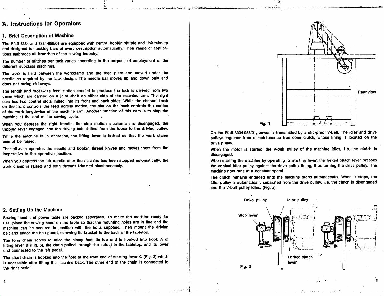
Rear
view
Fig. 1
On
the
Pfaff 3334-958/01,
pulleys together from a maintenance free cone clutch, whose lining is located on the
drive
pulley.
When
the
motor is
disengaged.
When
starting
the
the conical idler pulley against the drive pulley lining, thus turning the drive pulley.
machine
now
runsata
The clutch remains
idler pulley is automatically
and
the
V-belt
pulley
power
started,
machine by
constant
engaged
idles.
Is transmitted by a slip-proof V-belt.
the
V-belt pulley of
operating
speed.
its starting lever,
until the machine
separated
(Fig. 2)
from the drive pulley, i. e. the clutch is
the
machine
stops
automatically. When it
The
idles,
the
forked clutch lever
i.e.
idler
and
the
stops,
disengaged
drive
clutch is
presses
The
the
2.
Setting
Up
the
Machine
Sewing head and power table are packed separately. To make the machine ready for
use, place the sewing head on the table so that the
mounting
holes are in line and the
machine can be secured in position with the bolts supplied. Then mount the driving
belt and attach the belt guard, screwing its bracket to the back of the tabletop.
The long chain serves to raise the clamp feet. Its top end is hooked into hook A of
lifting
lever B
end
connectedtothe
The
short
(Fig.
chain is
6), the chain pulled through the cutout in the tabletop. and its lower
left
pedal.
hooked
into the
lioieatthe
front
end
of starting lever C (Fig. 3) which
is accessible after tilting the machine back. The other end of the chain is connected to
the
right
pedal.
Drive pulley
Stop
lever
Idler
pulley
.=j
\
I
1
*
V \
^
—V
-I
i I
Forked
clutch
lever
Page 5
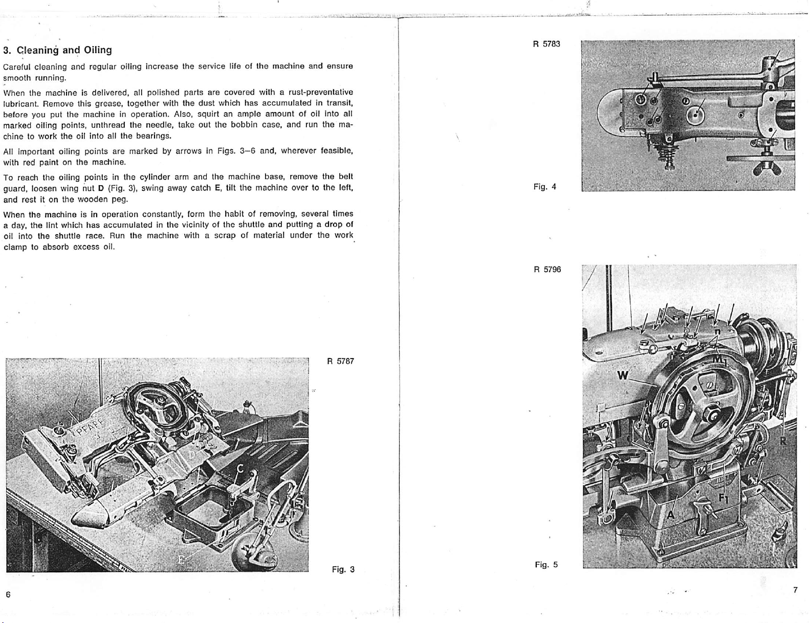
3.
Cleaning
Careful cleaning and regular oiling
smooth
When
the
lubricant.
before
marked oiling points, unthread the needle, take out the bobbin
chinetowork
All important oiling points
with
red
and
Oiling
running.
machineisdelivered,
Remove
you put
paintonthe
this
the
machineInoperation.
the
oil
into
machine.
grease,
all
are
all
together
the
increase
polished
bearings.
the service life of the machine and
parts
are
with
the
dust
Also,
squirtanample
marked by arrows in Figs.
covered
which
with a
rust-preventative
has
accumulatedintransit,
amount
case,
3-6
and, wherever feasible,
of oil into all
and run the ma
ensure
To reach the oiling points in the cylinder arm and the machine base, remove the belt
guard, loosen wing nut D (Fig. 3), swing away catch E, tilt the machine over to the left,
and
restiton
When
the
a day,
the
oil into
clamptoabsorb
machine
lint which
the
shuttle
the
wooden
is in
operation
has
accumulatedInthe
race.
Run
excess
oil.
peg.
the
constantly, form
vicinity of
machine
with a
the
habit of removing,
the
shuttle
scrapofmaterial
and
several
putting a
under
the
times
drop
work
of
R
5787
_ ,
&•••'
mi
m
Page 6
Certain
with
Therefore,
Since
andisnon-resinous,
sewing
mediedbylavish-oiling.
the
Pfaff
dirt
and
oil
sparingly
sewing
troubles,
lint in
machine
usenoother
suchasskippingofstitchesorthread
Excessive
the
but
regularlyl
quantities
machine
oil No. 280-1-120122
oil.
and
cause
of oil
hard
has
are
liable
running.
the
correct
breaking,
to soil
lubricating
cannotbere
the
workormix
properties
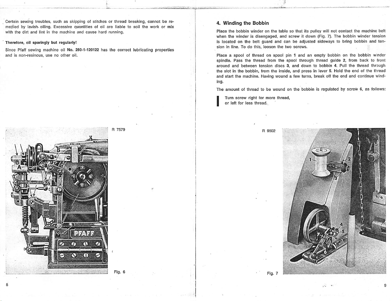
4.
Winding
Place
the
when
the
is
locatedonthe
sionInline.Todo
Placeaspoolofthreadonspool
spindle.
around
the
slotinthe
and
start
ing.
The
amountofthreadtobe
I
Turn
or
the
Bobbin
bobbin
winderonthe
winderisdisengaged,
belt
guard
this,
Pass
the
thread
and
between
the
machine. Having
screw
left
for
bobbin,
right
less
tension
from
for
thread.
and
loosen
from
discs3.and
the
wound
woundonthe
more
the
thread,
tablesothat
and
screwitdown
canbeadjusted
two
screws.
pin 1
and
the
spool
through
inside,
and
a few turns,
its pulley will not
(Fig. 7). The
sideways
an empty
thread
downtobobbin
pressinlever
break
bobbinisregulatedbyscre^6,as
contact
bobbin
to bring
bobbinonthe
guide
2, from
4. Pull
5. Hold
off
the
the
end
the
winder
bobbin
bobbin
back
the
thread
endofthe
and
continue
machine
tension
and
winder
to front
through
thread
wind
follows:
belt
ten
• J R
J
7579
Fig.
R
9502
; ^
' / .k'
6
Page 7

5. Threacflng
To remove
latch
bobbin
Next,
in
the
delivery
three
the
and
pull
drops
insert
the
case.
Puii
eye
2 (Fig. 10)
inchesofthread
the
Bobbin
empty bobbin,
out
bobbin
out
full
bobbin
the
thread
and
hanging
Case
open
the
cap
case
and
bobbin. When
into
the
bobbin
into
slot
1 (Fig. 9}
through hole 3 in
from
the
bobbin
on the cylinder arm. lift
you
release
case,asshown
and
drawitunder
the
position finger (Fig. 10). Leave
in Fig. 8,
the
case.
the
the
latch,
and
tension
bobbin
the
hold
spring
case
empty
it firmly
into
about
yv-j'JyCj
6.
Selecting
All Pfaff 3334
fabricsonModelCmachines,
standard
The
needle
weight, in
rule,
select
dense
and
\
For
best
Select
the
the
Correct
machines
needle.
size
should
any
case,
the
needleasthinaspossible,
resistant
results,
useasmooth,
proper
the
materials.
needle
are
be
thread
from
Needle
regularly fitted with
useaSystem
selected
must
supple
the
in
accordance
pass
thread
following
System34needles.
332
needle
with
freely
through
but
not
too
withamoderate
table.
whichisslightly
the
thread
size
the
needle
thintorisk
needle
twist.
eye.
To
longer
and
As a
breakage
sew
than
the
general
thicker
the
fabric
in
Fig. 8
When inserting
fn
the
shuttle
the
race
bobbin
ring
tween position finger and
hearitsnap
into
place.
and
case,
that
edge
make
the
loose
of slot.
Fig. 9 Fig. 10
sure
that
the
position finger
endofthread
Press
against the bobbin
does
not
enters
get
case
the
jammed
until you
slot
be
Needle
Size
70
80
90
100
110
120
insertanew
go. Make
sure
needle
the
Cotton
100/3
100/4
80/3
80/4
70/3-60/3
70/4-60/4
50/3-40/3
50/4-40/4
30/3
30/4
30/6
24/3
24/6
into
long
the
openingofthe
groove
faces
Silk
120/3
100/3
80/3
70/3
60/3
50/3
needle
toward you.
140/3-120/3
120/3-100/3
100/3-
clamp
Synthetic
80/3
70/3
60/3
50/3
and
push
Linen
70/3
60/3
50/3
40/3
it upasfarasit will
10
11
Page 8

7.
Threading
Lead
stand,
the
then
the
thread
from
downtospool
Needle
the
spoolupthrough
pin 1 on
hollow pin, from top to bottom,
left
around
and
4,
over
thread
check
to left through
between
the
thread
needle eye. Leave
between
nipper
tension
spring5,below
hole in
take-up
spring11and
about
three
the
thread
guideatthe
the
machine
thence
below
discs3,clockwise
thread
guide
lever 8. down
needle
thread
bar,
arm
guide2,over
around
6, up
and
and
through
and
from front to
(Fig. 11).
and
behind
inches of thread hanging from the
topofthe
PassItthrough
and
between
guide
thread
guides9and
back
needle
thread
from right to
tension
discs
7, from
through
eye.
the
right
10,
the
8.
Regulating
the
Thread
Tensions
The neat appearance of the finished bartack greatly depends on the correct regulation
of
tensions.
catenationofthreads
will not kink on
be
balanced.
Set
the
lower
tension
will not be visible on the top
the
underside.
Both
tensions
The bobbin threod pulls the needle thread to the underside of the fabric
OS
the stitch Is being formed.
Causei Needle thread tension too weolc, or bobbin thread tension too tight.
Remedy: Increase needle threod tension or decreose bobbin thread tension.
threads
are
a little
tighter
The
following illustrations
are
Interlocked
baloneed
correctly.
than
In the
the
upper
tensionsothat
side
of the material and
show
hov/
center
oF the
the
material
tensions
because
the
the
should
both
con
thread
The neede thread pulls the bobbin thread to the surface of the fabric
as the stitch is
Cause:
Remedy: Decrease needle thread tension or increase bobbin thread tension.
Regulating
Set
the
the bobbin
Bobbin
thread
Thread
teiislon so
correctly. Make sure, however,
thread
will
notbecut.
Needle
Tension
that
being
formed.
thread
tension too tight, or
that
the bobbin thread will be pulled into the fabric
the
tension is not too light as otherwise the bobbin
bobbin
threod
tension too
weak.
Page 9

The.bobbirf
I
thread
tensionIsregulatedbythe
TurnItright
or
left
for
for
looser
tighter
tension,
tension.
small
screw
S (Fig. 9),asfollows:
The tension Is correct If you have to overcome a noticeable resistance when pulling
the
thread.
10.
Stopping
Upon completion of the sewing action, tripping lever F 1 (Fig. 5) Is
stop
tripping
the stop cam by a tension spring. At the
the
driving to the loose pulley to slow down the machine before It stops. Then the stop
link
snaps
Is
absorbedbydouble
chanism Is releasedsothat, by depressing the left treadle,
th^e
threads
If any trouble
pressing
Into the
down
the
segment
cut.
should
hand
Machine
on the rim of feed cam W and
same
stop
cam which
buffer springs. After
occur
stop
lever
while
A (Fig. 5).
stops
the machine. The momentum of the machine
the
madilne
depressed
stop
motion lever R pulled against
time, the belt shifter shifts the belt from
the
machine
Is In operation,
has
the
stopped,
clamp
stop
the
locking me
can
be raised and
the
machine by
by the
Regulating
the
controls
the
sive
the
closetothe
The
se'tting phase. Begin by setting top tension
that
fabric willbecontractedbythe
bnecome
applies only to tacks
es). The main
sufficient
threads
9.
Don't start the machine
operation.
When you
loosetothe
the
Needle
Thread
Pfaff 3334-958/01
the
thread
threadIstrimmed
amountofthread
other
hand,
needle
lower, or main,
the
thread
has
tension
easily. If
through
the
tensionIstoo
eye.
tension
willbedrawn
operative until the machine
made
tensionIsreleased
amountofthread
are
trimmed.
Starting
the
Machine
unless
depress
the right treadle, the brake Is released and the belt shifted from the
driving pulley. This action
Tension
two needle thread tensions. The top tension Sp 1 (Fig. 11)
during
the
thread
the
the
Sp2
Into
first long
tensionIsset
tension
(Fig. 11)
tight,
and
the
controls
Spl
the
material
stitchesofthe
has
made three or four stitches. (This naturally
trimming
thread
action
and
shouldbesetsothat
too
light,
the
knives
will
drawanexces
the
needle
thread
will
notbecut.
willbetrimmed
the
needle
and
then
adjust
properly.Inordertoprevent
tack,
thread
main tension
the
lower
too
during
tension
early
the
and
Sp2
that
will
If,
too
stitch
on flimsy material and Involving extremely long Initial stitch
again
before
the
last
tying stitch Is
canbepulled
through
the
tension
you have thoroughly familiarized yourself with Its
starts
the
machine.
madesothat
mechanism
before
mode
To acquaint yourself with the operation of the machine, turn the driving pulley by hand
and study the Individual
stitching on a
piece
phases
of material.
of operation. Then thread the machine and try out the
Whife the machine Is In operation, a locking mechanism prevents the work clamp from
being raised and the knives from cutting the thread. Conversely, the machine cannot
be
started
while
the
work,
clampIsraised.
on
so
the
not
the
a
11.
Trimming
The
thread
before
the
cam
u (Fig. 6)
causes
the
the
of
needle
are
caughtbythe
upper
and
ing tack. On completion of
the
take-up
nipperIsclosed
When
the
lever
drops
to
the
knife
down
from
pulls
the
the
trimming
last
stitdiIsmade,
operates
knivestobe
descends
lower
lever
and
left
treadle
Into a
bar
the
knife
needle
thread
Threads
knives
are
locatedonthe
main
tensionSp2 Is
the
vertical knife
movedtothe
between
knife
tensionstoprovide
has
traps
Is,
recessInthe
and
the knives which swing forward.' As a result, the
tips
them
tips.
The
the
last
almost
reached
the
needle
depressed,
onto
endupthrough
for
knives
stitch,
the
control
the
cutting
operative
the
pullanadequate
sufficient
the
thread.
slotofthe
the
undersideofthe
bar
tripping lever
position.Asthe
last
stitch
thread
the
machine
highest
rolleratthe
edges
needle
released.Atthe
and
and
the
amountofthread
for
the
stops
point of Its
top
endofthe
knife
cam.
and
are
hole.
needle
plate.
same
time,
knife
barMand
knives
swing
upper
and
lower
through
first
stitchesofthe
automatically. At this
stroke
and
the
knife
bar
This
motion Is
transmitted
threads
trimmed.
The
thread
Shortly
knife
thereby
forward,
threads
the
follow
stage,
thread
tripping
slide
wiper
14
15
Page 10

.12.
Feeding
Since
this machine
rial is moved
The
feed
plate E (Fig. 12), between which the work is clamped. Depending on the
the
machine
pensating
The compensating work clamp (shown in Fig. 12) features two feet which yield inde
pendently
on
the
material,
needle
than
the
lengthwise
motion is
and
work
clampisused.
against
on
the
Material
derived
the
spring
it is
other.
has
used
a rigid
and
across
from
natureofthe
pressuresothat
for
conditions
needle
the
the
feed
worktobe
bar
which
arm to form
cam
and
performed,
each
foot
where
the
does
not swing
the
desired
conveyedtowork
eitherastandardora
exerts
the
materialisthickeronone
sideways,
tack
design.
clampDand
same
amountofpressure
the
mate
feed
subclass
com
sideofthe
Eyelet-end buttonholes look nicer and wear longer if their square end is closed together
before it Is barred. For this purpose the Pfaff 3334-958/01-5
are
work clamp whose feet
closed showing the fabric together toward the middle. The correct position of the
assured
clamp
by a guide entering the buttonhole slot. This guide is located
feet.
spread
apart
when they reach the material and then
has
been
fitted with a special
bar
between
are
the
13.
Regulating
The
amountofsideways
and
varies
(Fig. 13)
of
I
As a
together,
too
larly In
facilitate
accordance
is
and
MoveIttoward
or
over
resultofthis
while
far
apart,
leatherorplastic
correct
with
each
move ball
from
the
the
with
the
Feed
Across
travel of
subclass.
stud
G in
you
for
more
you
for
less.
adjustment,
total
tack
looks ugly. And conversely, if they
adjustment,
the
styleoftack
the
numberofstitches
material,
the
Motion
the
work
To
adjust
the
the
slot
of feed
sideways
stitches
the
thread
maximum width of
madebyeach
clamp
depends
feed
across
across
clamp
travel,
willbelengthenedorpacked
does
not
is likely to
sideways
subclass.
on
the
motion,
regulatorH,as
change.Ifthe
are
packed
cut
through
travel
designofthe
loosen
stitches
too
has
wing nut F
follows:
more
close,
the
material.
been
closely
are
placed
particu
limited in
tack
To
f
mm
R
5797
Fig. 12
Fig. 13
Page 11

14,
Regulating
The lengthwise clamp travel is derived from the control slot on the back
feed cam. This motion is conveyed to the work clamp by
(Fig. 14), feed regulator
the
Feed
Lengthwise
Motion
means
post
K. feed plate carrier b and arch clamp frame L.
side
of the
of feed regulator a
To adjust the feed lengthwise motion. loosen screw B and move hinge block J, as fol
lows.
Move it upasfarasIt will go to
clamp travel to zero, or down to
reduce
increase
lengthwise
travel.
Note that for certain tack designs which are not'actually bars, hinge block J must not
be moved if
the
proportionsofthe
design
are
to be
preserved.
^ R
7576
K-
15. Dismantling
If the machine is
Let the machine run until it
Open the cylinder bed cap. press down and
bobbin. Take out
shuttle by its center stud and
don't
get
lost.
the
used
screws
Shuttle
constantly,
Race
clean
stops.
h and I (Fig. 15)
pull
the shuttle
Tilt It over to the left, resting it on the
and.strip
race
pullitoff.
shuttle
from time to time.
Remove
the bobbin case and
race
ring d. Then, seize the
wooden
peg.
it out. Take care that the springs on screws h and I
The shuttle race proper need not be stripped for cleaning. Take a pair of tweezers and
remove pieces of thread that have accumulated In the area behind the shuttle race.
Then, with a toothpick or similar wooden instrument, clean the raceway of the shuttle.
Never
useametal
To
assemble
of the shuttle should point downward when you Insert it. Don't forget to
the
tool
shuttle
for
this
mechanism,
purpose.
reverse
the
above
procedure.
Note
that
replace
the
point
the
springs on screws h and i and to put a drop of oil into the shuttle race after it has
been
re-assembled.
The springs on screws h and I hold the shuttle race ring in elastic suspension and pre
vent damage to the machine if thread should jam in the raceway. Pieces of thread or
lint
that
should
have
entered
the
race
can
thusbeeasily
removed.
Fig. 14
R
5790
Fig. 15
-V-i-
h—^
Page 12

B.
Instructions
16.
Ceniering
Needle
screw
In
as
The
the
make
the
17.
The
form the loop) of
needle
Its
center
If
Ttie
Setting
See
has
the
adjustment
necting
To
and
the
same
shuttle
same
bar
frame
e, which
the
needle
hole,
appropriate.
needle
plate
two
set
screws
sure
the
needle
plate.
Timing
Pfaff 3334-958/01 Is fitted for a
In timing
stroke
adjustmentisrequired,
21),
which
shuttle
positiononthe
that
passed
point of
double
seeIfthe
latter
the
rise
gauge
the
shuttle,
and
lineofthe
canbereached
driver
the
Needle
the
pointofthe
the
the
is
studtothe
check
Is at Its right
whether
driver
time.
and
for
the
NeedleInthe
F (Fig. 12) is
passes
loosen
hasanInterchangeable
and
groove
on Its
Shuttle
V32",
No.
88013605
apply
risenVnof an Inch,
needle.
crankIspinnedtothe
shaft
cannot
BaratCorrect
lowest point of Us
shuttle
required
needle
the
above
bottomofthe
the
driving
the
Mechanics
Needle
hinged
to a
throughanelongated
screweand
press
the
undersideIsexactlyInline
move
InsertupoutofIts
needle
or 2.4 millimeters. To facilitate this adjustment,
whichIsavailableonspecial
this
rule:
When
the
pointofthe
This
setting
ensures
loosen
shuttle
driver
through
shuttleIsopposite
should
loosen
pointofreversal.
needle
holesaiandajon
be
adjusted.
Height
stroke
and
be Vu" (1.5 millimeter)
the
clamping
bar,
and
move
settings,
needle
pulleyIsturned
bar
bring
eye
should
Is flush with
Hole
studatits
holeInthe
the
Insert.Ifthe
bar
rise
the
needle
proper
screwsbiand
rear
endofthe
the
center
risen
screw,
the
latterupor
the
needletothe
Also
checkIfthe
clockwise
reach
their
upper
end
and
casting.Tocenter
needle
bar
frametothe
needle
holeIsdamaged,
seat.InInsertinganew
with
the
knife
(amountofneedle
request.
has
passed
shuttle
shouldbejust
loop
formation.
b: (only bi
the
undersideofthe
shuttle
driver
lineofthe
V22
of an Inch. When In
above
which
the
topofthe
or
pointsofreversalatexactly
needle
the
top of
fastens
down,asappropriate.
amountofneedle
counter-clockwise.
the
lowest
heldInplace
guide
rise
use
the
lowest
opposite
visible
cylinder
shaftsothat
after
this
the
needle
needle
point
of its
shuttle
the
needle
rightorleft,
loosen
Insert,
groove
required
the Pfaff
point
the
In Fig.
arm.
the
latter
position,
eye. If
bar
con
stroke
driver
when
riseIsthe
Both
the
the
Adjust the feed
across
motion so that the right and left hand
ends
of the feed plate slot
are equidistant from the needle hole when the feed plate Is at the extreme right or left
of Its throw. Check this setting for the longest and the
All
by
no further
If
readjustment
1. After
motions
roller
^
gulatorH.Tighten
In
to
of
2. Move ball
plate
3.
Push
4.
Turn
plate
rightorleft of Its throw. If
m (Fig. 16)
5. Move ball stud G (Fig. 13) over from you as farasit will go, setting
plate
6.
Repeat
I2
crosswise
its
this setting, move ball
other
If
Pi (Fig. 18) slightly to
H.
shouldbetimed very carefully.
adjustment
shouldbemade,
Is required,
the
stud
for
the
the
slot
for
and
n (Fig. 16)
machine
stud
the
belt
driving pulley
are
the
the
travel of
has
completed
Pi (Fig. 13)
the
and
nut
G (Fig. 13)
longest
shifter
crosswise
over
equidistant
and
set
the
feed
shortest
check
crosswise
outlinedInpar.4above.Ifadjustmentisrequired,
and
the
work
stud
and
make
sure
the
the
feed
plate
should
the
R
Once
unless
proceedasfollows;
the
sewing
center
the
studInthe
securely.
toward
from
and
from
adjustmentIsrequired,
move
G (Fig. 13) from
feed
move
rightorleft In
5782
youasfarasit will go,
travel.
youtorelease
chedt
whether
the
needle
plate,asappropriate.
travel.
studRlengthwiseofthe
clamp
Is exactly halved by
plate
does
sidewaysInspiteofthis
the
absolutely
the
hole
not
the
correct
cycle
elongated
the
right
when
loosen
Then
one
endofthe
move
elongated
shortest
necessary.
and
stopped,
brake.
and
the
feed
tighten
feed
the
sideways.
minute
hole of feed
feed
across
setting
has
been
loosen
holeoffeed
setting
clamp
left
hand
endsofthe
plate
is at
screwhand
both
screws
clamp
loosen
across
shaft
needle.Todouble
slotInregulator
adjustment,
across
motion.
obtained,
the
across
and
the
binding
securely.
and feed
move
nut on
re-
feed
feed
extreme
screw
screws
until
the
check
H to
the
stud
regulator
h, R
18.
Adjusting
The
feed
the
rolleronstudPifollows
As
curvatureofthe
feed
across
of
the
cylinder
the
Crosswise
across
motionIsderived
slotIsconveyedtofeed
shaftSand
arm.
feed
Clamp
from
the
plate
Travel
the
slotonthe
channel
carrierU,and
track,
across
frontoffeed
the
throw
whichIsInitiatedbythe
regulatorH,connection
causes
the
latter
to move
cam
Q, ball
W (Fig. 13).
stud
crosswise
R,
Fig.
• /
,'
I
m I2 n
16
Page 13

19.
Adjusting
the
feed lengthwise
W {Fig. 17). Motion is
block
J (Fig. 14),
To
adjust
Turn
the
driving
clamp
feet
If
the
machine
sign
are
correctly
paper
under
Foraprecise
17)
and
move
tighten
the
the
feed
the
lengthwise
pulleybyhand
slot
when
makesabar-type
centered
the
clamp
adjustmentofthe
the
studinthe
nut
securely.
Lengthwise
motion
is derived
transmitted
regulator
clamp
these
feet
over
and
examine
Clamp
from
from
the
postK,feed
travel,
move
and
check
reach
the
seam,
also
the
long
the
feed
lengthwise
elongated
Travel
the control slot on the back of feed cam
rolleronstud
plate
carrierband
hinge
blockJdownwardasfarasIt will
whether
extreme
check
stitches.Tocheck
stitch
pattern.
motion
holeoffeed
P2 to
the
the
needle
hole
positonsoftheir
whether
the
this,
loosen
regulator
plain
the
feed
regulatorV.hinge
work
clamp.
remains
stitchesInthe
placeapiece
nutonstudP2(Fig.
V,asrequired.
within
lengthwise
go.
the
travel.
de
of stiff
Then
20.
Timing
The
feed cam is located on the right hand
operator). It controls both the feed lengthwise and
motion
penetrates
the
Feed
Cam
side
of the machine arm (as
the
begins
after the
needle
has
risen
clear
of the fabric and
the material again. If the feeding begins too early or
ing motion is retimed by turning the cam on its shaft.
Todothis,
shaft
in
cam
loosen
nut
Y (Fig. 18)
(the
cam
canbeturned
positioning block 2). After
R
5793
within
r
and
studXand
the
the
adjustment,
limits
turn
setbystud
tighten
feed
across
the
feed
X riding in
studXand
seen
from the
motions. The feeding
ends
before the
ends
too late, the feed
camonthe
the
nut Y
transverse
elongated
securely.
W'
needle
hole
-01
•••Vx
• .
Fig.
17
Fig.
fell
Yt®fX
18
Page 14

21.
Timing
Shortly before the machine stops, the knife cam
the Inoperative to the operative position, and after the
tripping
in
turn,ispinnedtothe
lever t
the
(Fig.
Knife
19)
Cam
and
knife
transverse
barM.Knife
shaft.
causes
the knives to be moved from
machine
has stopped, operates
cam u is screwed to hub cover f
which,
The four screwholes in hub cover f are elongated so that the position of the knife cam
on the shaft can be adjusted after loosening the four screws q.
Set the
point of its stroke and begins to descend for the last stitch. Since gear ratios
each
deviations. If additional adjustment is required, reset the knife
following
tips when It
next
knife
subclass
cam so that
machine, no hard and fast rule can be given for the elimination of minor
knife
motion
begins
when
the needle has passed the
bar
as instructed in the
chapter..Note as a general rule that the needle should pass between the knife
descends
seam.
for the last stitch of
one
seam
and the first four stitches of the
highest
vary
with
22.
Adjusting
The
throw initiated by knife
platebymeansoftripping
the
Knife
Bar
cam
u (Fig. 19) Is
leverXand
transmittedtothe
knife
bar
l\A.
knives
below
the
needle
The knife bar carries a rack at its front end which meshes with the knife carrier pinion.
Its
rear
endisconnected
Loosen
Vaj"—Vii"
when
No
bobbin
Instructions
screwsrand
the
gauge
thread
(7—8
millimeters) between tip of bobbin
knife is
Inoperative
Is required for this setting. Simply adjust the knife bar until the tip of the
knife is in line with
giveninthe
to tripping lever t by
s (Fig. 19)
and
(Fig. 20).
preceding
set
knife
the
top
chapter.
means
barMso
left
edgeofthe
of an adjustable fork.
that
there
is a
thread
knife U and the
shuttle
clearanceofabout
needle
race.
Note
also
hole
the
msmmm
^-•Greiferbahn-kanle
i *
Page 15

23.
Changing
Th'e knives
used
-wooden
Next,
The knife
b (Fig. 22) in
needle
pullingitforward.
shouldbesharpened
constantly.
peg.
remove
assembly
plate
screws
Open
pinion
the
the
To
feed
Knives
strip
the
stud
can
and
cylinder
also
plate
from time to time, particularly
the
knives,
tilt
the
bed
cap,
bracket0and
machine
loosen
the
knife
overtothe
nut M (Fig. 21)
assembly.
be removed from above. To do this,
and
pull
the
plate
out
of its
remove
the
needle
plate
with
mount.
the
left
and
loosen
Then
attached
when
and
take
take
knife
the
machine
restiton
out
hexagon
out
assembly
screw
screw
the
the
four
by
N.
The
knives
are
securedtothe
screw
and
strip
the
Is
new
In
replacing
tighten
knives.
the
screwasecurely.
knives.
knives
make
(Fig. 21) so that the knife
replaced.Toreplace
dure.
the
knife
Sharpen
sure
The
meshing
bar
need
knife
assemblyinthe
carrier
them
they fit in
teethofthe
onlybyscrew
with a knife
the
knife
a (Fig. 22).
grinderorexchange
carrier
groove
rack
and
the
pinion
Take
correctly.
not be readjusted after the knife assembly
machine
simply
reverse
the
above
are
out
them
spotted
has
proce
this
for
Then
been
R
5952
•-
Fig.
21
Fig. 22
24.
Adjusting
When you
wardtothe
may swing slightly
edge
this
If
the
knife
depress
operative
when
protrudes
the
Knife
the
beyond
the
treadleisdepressed
from
of regulating block Gi in
left
treadle
position.
the
the
the
Motion
after
During
right
edgeofthe
edge,
slotofthe
the
this
completely.
loosen
lifting lever.
machine
operation
cylinder arm,
lock
nut
has
stopped,
the
tip of
H (Fig. 17)
the
knives swing for
the
bobbin
thread
knife
butitshouldbeflush with
and
adjust
the
position
Page 16

25. Adjusting
Stop
motion
vertically.
end.
Both
the
catch
Into
the upper
chine. To adjust, loosen the hexagon screws.
When
you
meters) between the face of the stop link
the
Stop
Motion Lever
leverp(Fig.
23)
carriesacatch,
Ei,atits
The spring-loaded tripping lever Fi carries an adjustable
and
the
latch
should
beso
make
notch
this
of catch Ei
adjustment
when
also
see
adjusted
the
that
(Fig.
that
right
treadle is depressed to start the ma
there
is a
24) and the highest point on the face of
the stop cam.Ifadjustment is required, loosen screw t
the
groove
of tripping lever Fi.
; R
lower
end,
which
latch,
latchGiwill
leap
clearanceofabout
(Fig.
23) and reset
5485
canbeadjusted
Gi at its rear
about
halfway
(2
milli
latchGiIn
26.
Adjusting
Adjust brake lever R (Fig. 23) so
between
machine
V«4"
To
Start
In
Loosen
resistance.
Stop
cam. Check whether the
meters)
If
back
I
hinged
is In
(2 millimeters) when the machine
adjust,
the
the
central
the
the
against
further
accordingly.
Make
surfaceofthe
the
Brake
brake
operation.
follow
this
procedure:
machinebyhand.
position
nut of
stop
Then
turn
the
machine
adjustmentIsrequired,
sure
completelysothat
spring
the
brake
driving
LeverofMachines
shoeKand
Also
Loosen
and
lighten
screwvand
screw
brake
pressure.
shoe
pulley
with
that
there
is a
clearanceofabout
the
braking
make
sure
has
the
two
both
screws
turn
in
oneortwo
the
lever
can
loosen
exertsasufficient
when
the
surfaceofthe
the
brake
lever
stopped.
screws
q (Fig. 23),
securely.
the
screw
out
turns.
stop
link
snaps
be pulled off the pulley
the
two
screwsqand
amountofpressureonthe
machineisbeing
Round-Belt
driving
can
be pulled off
set
until It
turns
Into
the
stopped.
Drive
V32"
(7 millimeters)
pulley
hinged
brake
freely, without
grooveofthe
about
move
the
Slop
when
the
shoe
V<4"
(2 milli
brake
braking
com
the
pulley
K
any
stop
shoe
Fig. 23
Fig.
24
Stop
segment
tripping
tripping
and
dog
Slop link
Stop motion lever
Tripping
lever
Page 17

27.
Adjusting
Tripping
adjusted vertically.
dogLi(Fig.
depresses the
rely.
As a general
ters) between the tripping dog and the rim of the feed cam when the machine
stopped
(Fig. 23).
28. Adjusting
the
Set
tripping
rule,
the
Tripping
23),
it so that the
Lever
which
is located at the
stop
tripping
front
segment
end of the
on the rim of the feed
dog far enough to ensure that the machine
there should be a clearance of aboutVbon an
Stop
Tripping
Segments
tripping
will
lever,
be stopped secu
inch
(3.5
can be
millime
cam
has
Although the
error,
I
The
without
The pressure Is regulated by stop screw d (Fig. 18). Some bartacks which feature very
long crosswise stitches (without Intermediate stitches) require a sufficiently long
of
thread
be
pushed
If
there
adjusted
the
correct
following
pressure
rule
maybehelpful:
pressureIscorrectifthe
breaking.
with which to begin
back
slightlysothatitcan
are
several
separately.
thread
nipper
of the thread nipper Is normally established by trial and
thread
can
the
tack. On
fall
segments
justbepulled
machines
earlier
arrangedonthe
into
making
the
through
such
tacks
recess
on
feed cam,
the
the
rimofthe
each
thread
nipper
finger f
should
has
end
cam.
to be
The number of stop tripping segments which are arranged on the rim of the feed cam
varies with each
To
adjust
Turn the
passed
stop cam. When the machine has stopped, tripping dog Li should be positioned just
behind
ping dog Li should contact the rim of the feed cam instantly.
If
move the segment back or forth on the
If
tripping
the stop
the stop
the
feed
29. Timing
The needle thread must be trapped when the machine stops. If this condition is not
met, adjust by loosening screw e
follows:
Toward
The
the
Another rule
the needle has reached the lowest point of its stroke when making the first stitch. As
the sewing cycle continues, the thread should remain loose until the take-up lever has
reached a point about Vu" (15 millimeters) below the highest point of its stroke. This
condition
sive
you
finger
recess
stitches
If the above condition is not
thread nipper tripping
Over
from
the
driving
tripping
cam
the
subclass
stop
pulley
dogLi(Fig.
tripping
has
Needle
and
tripping
segments,
until
the
23)
segment,
segment needs
more
than
Thread
Nipper
threadIstrapped
ranges
from 1 to 6.
proceedasfollows:
tripping
and the stop
without
adjustment,
rim
one
stop
tripping
(Fig.
18) and
segment to be adjusted
link
has snapped into the groove of the
touching
of the cam, as required.
earlier
it.
On restarting the
loosen
the
segment,
moving
two
each
finger f on tripping lever c as
(MiinFig.
screws n
has
to be set
5) has just
machine,
(Fig.
separately.
5) and
is positioned correctly if Its tapered side just slips over the front edge into
on the rim of the cam when the machine stops.
that
also
appliestothe
the
you
must be
thread
observedisthat
nipper
segment
Needle
threadIsreleased
the
needle
thread
mustbereleased
initial
phase
of the
second
remains
met,
h (Fig. 18), as follows:
inactive. i
adjust by loosening the two set screws and
earlier
stitch,
whereas
for all
before
succes
moving
trip
30.
Changing
A powerful buffer
the
momentumofthe
chine is
est point of its stroke and descended V8"-Vu"
slowed
the
Buffer
springislocatedinthe
down
first
machine
and
Fig. 25
Spring
whenItstops.Ifthe
stopped
hollow driving pulley
only when
and
servestoabsorb
spring
works
correctly,
the
needle
bar
has
passed
(3-5
millimeters) and the take-up lever
*•-
i'-'
the
the
ma
high
Page 18

has almost reached the top of Its stroke.
stress,
it may
becomes
become
evident
weakoreven
when
the
machine
the take-up lever do not always stop at the
stop
beforeithas
reached
the
top of Its
Since
break
after
ceasestostop
same
stroke
and
this spring is
some
time by fair
evenly or when
subjected
wear
the
positions. As a result, the
may be
brokenbythe
to excessive
and
tear.
needle
bar
needle
thread
This
and
may
wiper
upon lifting the work clamp. To correct this and similar conditions, exchange the buffer
spring,asfollows:
Remove tension
studQand
Next,
take
ken
buffer
Insertion of a new spring Is greatly facilitated by the
which will be
strip
out
the
spring.
supplied
springs
stop
N and 0 (Fig. 25), loosen
motion lever p (Fig. 25)
four
screwsb,strip
by us on
special
cap
request.
and
ring A
brake
and
screw
K (Fig. 26), pull out hinge
lever R.
remove
use
stop
camSand
of a special wrench (Fig. 27)
the
bro
Proceed,
as
shown
in Fig. 27, by
insertingasuitable
pulley. Then rotate the pulley until punch D rests
Insert
the
buffer
spring
into
the
the
wrench,
block
.
compress
sure
Then
lever
contacting
the
the
flat
replace
and
the
and
push
the
spring
sidesofthe
the
stop
stop
motion
the
loose
and
cam
wrench
endofthe
place
check
and
lever.
R'5788
receptacle,
over
the
Novotext
blocks
the
the
spring.
face
cap
place
endofthe
segment
toward
ring
against
the
Now, with
the
and
screw
punch
into
hole
the bearing bracket.
loose
check
blockonthe
arm shaft, with
the
wrenchinyour
between
segment.
them
both
down. Attach
I of
the
check
the
driving
stud
loose
check
left
hand,
blocks. Make
the
brake
of
v.'.usi
• -"-i
Fig. 26
Fig. 27
Page 19

31.
To
adjust
Adjusting
the
Cone
the clearance
ClutchofMachines
between
V-belt
pulley
(Idler
with
pulley)
V-belt
1 and
Drive
drive
pulley
7 after
the machine has stopped, loosen the nut of eccentric 5 aiid turn the eccentric to the
rightorleftbyhand
of the
V-belt
pulley
pntll
the
forked
clutch
against the arm shaft
lever
bearing.
3 has
pushed
Hold
the eccentric in this
the
ball-bearing
collar
position
with an open-ended spanner and tighten its nut.
32.
Trouble
Sewing
troubies
followed. If
the
fault.
Shooting
should
trouble
rarely
should
occur
if aii
nevertheless
the
instructions given in this
occur,
the
following hints wiii
book
heip
are
you
carefully
locate
Q
1 = V-belt pulley (idler pulley)
2 = Engaging
3 =
Forked
4 = Leaf
5 =
6 =
spring
Adjusting
Clutch
lining
clutch
eccentric
disengaging
lever
collar
and
7 = Drive puiiey (take-up spring housing)
Fig. 28
Machine
1.
2.
3.
4.
5.
Thread
1.
2.
3.
4.
5.
Needle
1.
2.
3.
4.
5.
6. Work
Machine
1.
2. Mechanism
3.
4.
Skips
^Needle
Needle
Needie
Needle
Shuttle
For
Needle
Thread
Poororknotty
Thread
Needie
Needle
Buffer
Knives
Machine
bent.
incorrectly
too
rise
set
Breaks:
anyofthe
point
caught
tensions
Breaks:
bent.
too
spring
improperly
clamp
sewn
on.
Works
Uck
of
oil.
Piecesofthread
Machineorline
Stitches:
inserted.
fine
for
the
thread.
inaccurately
too
far
causes
bluntorworn,orburrs
between
thread
too
fine
for
broken.
feeds
while
timed,orneedle
away
from
enumerated
tension
used.
looseortoo
the
fabric,ordeflectedbyhard
timed.
needleisdowninmaterial.
not in line with
Heavily:
clogged
by inferior
jammedinshuttle
shaft
belt
needle.
discs.
tight.
neediesothat
iubricants.
too
long.
above.
and
race.
set
sharp
too
highortoo
edges
needle
iow.
on
needle
spotsinthe
strikes
buckle or
plate.
material.
clasp
to be
34
35
 Loading...