

Page 1
IS'
' " (D
(TOFF)
Automatic
SERVICE
Lockstitch
3334
Bortocker
MANUAL
Page 2
Foreword
Pfaff sewing machines
are
quality products. Constant checks ore
being made throughout the production process to ensure that o
But
high quality standard is maintained.
machine
results
has to be operated and serviced
aretobe
obtained.
even the best sewing
skillfuify
if satisfactory
This book has been compiled cs a source of information for all
Pfaff mechanics servicing Pfaff 3334 automatic bartackers and
will serve as a valuable guide in performing minor repairs and
adjustments.
We have made every effort to render the presentation of these
instructions as simple as possible and have included numerous
illustrations inordertoafford a better understanding.
G.M.PFAFF
Kaiserslautern
AG
Branch
Page 3
SERVICE
MANUAL
Automatic
PFAFF
Lockstitch
3334
Bortocker
Page 4
Contents
A.
Description
1.
General
and
Information
Operation
a. Purpose of Employment 6
b.
Application
Possibilities 7
Page
5
5
Operation
2.
a. Efficiency Rating 8
ModeofOperation
b.
c. Sewing Cycle 9
3. Mechanical Setup . 13
a.
Shuttle
b.
c.
d.
Thread
B. Instructions for
ond
Feed
Motion
Automatic
Trimming Action 20
Needle
Stop
Repair
Bar
Motion
Drive
.
13
13
18
30
1. Disassembly , 30
2. Assembly 31
3. Adjustment
a. Timing the Shuttle
and
Check-Up 33
and
Setting the Needle Bar ot Correct Height 33
b. Timing the Feed Motion 39
c. Timing the Thread Trimming Action 46
Work
d. Adjusting the
Clamp 49
8
8
e. Timing the Stop Motion 49
f. Timing the Thread
Nipper
and
Adjusting the Thread Tension 53
Page 5
4. Stitching-Off 60
a. Sewing
b.
Needle
Thread
c. Bobbin Winding 61
Needle
d.
e. Threading the Bobbin
f. Inserting the Bobbin
5.
Setting-Up
a.
Individual
b.
Bench
c. Individually Powered Machine on Power Benching
6.
Subclass
Threading 62
Case
Case
Power
Power
Drive
Drive
.
....
Conversion
a. Changing the Feed Cam 69
b. Changing the Knife Cam 70
c. Changing the Work Clamp Feet 71
d. Changing the Feed Plate 71
60
60
63
63
64
64
67
68
69
7. Trouble Shooting 71
a. Skipped Stitches 71
b. Thread Breaking
71
c. Needle Breaking 71
d. Heavy Working 72
e. Irregular Stopping 72
8.
Machine
Care
75
a. Cleaning and Oiling 75
b. Dismantling the Shuttle Race 77
Page 6
C. Electromagnetic Control 78
1.
General
a.
Information
78
Brief Description 78
b. Key to Symbols Used 79
Operating
2.
Instructions for X35
and
X45 Devices 80
a. Turning on Master Switch HS 80
b. Inserting the
Work
and
Operating
Foot Switch FS (1st Switch Position) 80
c. Starting the Machine by Operating
Foot Switch FS (2nd Switch Position) 80
d. Sewing Cycle
and
Automatic Stopping of Machine
....
3. Working of Device 84
a.
Master
Switch
HS
b.
Foot
Switch
FS 84
c.
Solenoid
d.
Solenoid
e.
Switch
4. Mounting
a.
Switch
b.
Lever
c.
Solenoid
d.
Switch
e.
Solenoid
EM
HM
and
Switch
ES
SS
and
Adjustment Procedures 87
ES
B
EM
SS
HM
80
84
84
86
86
87
87
87
87
87
D.
Subclass
1. Subclasses Having the
2.
Subclasses
Information
Having
the
Same
Same
Gear
Ratio 92
Knife
Cam
91
93
3. Subclosses Requiring Additional Parts 94
One
4. Principal Parts Varying from
5. Special
lock
6.
Organizational
Designs
Arranged
Parts 96
by Shapes 99
Subclass to
Another
....
95
Page 7
A. Description
1.
General
and
Operation
Information
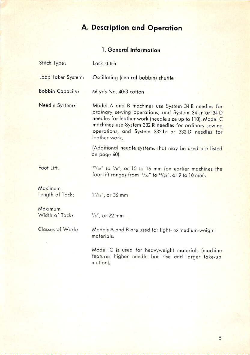
Stitch Type:
LoopTaker System;
Bobbin Capacity:
Needle System:
Foot
Lift:
Maximum
Length of Tack:
Maximum
WidthofTack:
ClassesofWork:
Lock
stitch
Oscillating (central bobbin) shuttle
66 yds No. 40/3 cotton
Model A and B machines use System 34 R needles for
Lr
110).
or 34 D
Model C
sewing
ordinary sewing operations, and System 34
needles for leather work (needle size up to
machines
use
System
332Rneedles
for ordinary
operations, and System 332Lror 332 D needles for
leather
work.
(Additional needle
on
page
60).
'V32"
to Vb", or 15 to 16 mm (on
foot lift ranges from "/as" to
1Vib",or36 mm
Va",
or
22 mm
ModelsAand Bare used for
materials.
systems
thot may be used are listed
earlier
machines the
'V32",
or 9 to 10
light-
to medium-weight
mm).
Model C is used for heavyweight materials (machine
features higher needle bar rise and larger take-up
motion).
Page 8
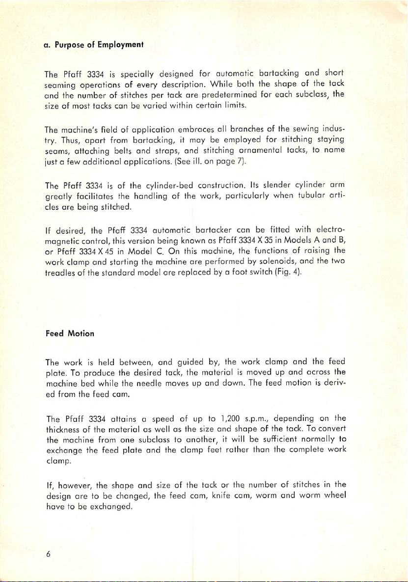
a. Purpose of Employment
The
Pfaff
seaming
3334isspecially
operationsofevery
designed
description.
for
While
automatic
both
bartacking
the
shape
and short
of the
tack
and the number of stitches per tock ore predetermined for each subcloss, the
sizeofmost
tacks
canbevaried
within
certain
limits.
The machine's field of application embraces oil branches of the sewing indus
try.
Thus,
opart
from
bartacking, it may be
seams,
attaching
justa few additional applications. (See ill.on page 7).
belts
and straps, and
employed
stitching
for
arnamentol
stitching
tacks,
staying
to name
The Pfaff
greatly facilitates the
cles
If desired, the Pfaff 3334 automatic bartacker can be fitted with electro
magnetic
or Pfaff 3334X45 in Model C. On this machine, the functions of raising the
work clomp and storting the
treadles of the standard model ore replaced by a foot switch (Fig. 4).
Feed
The work is held between, and guided by, the work clamp and the feed
plate. To produce the desired
machine bed while the needle moves up and down. The feed motion is deriv
ed
The Pfaff 3334 attains a speed of up to
thickness of the material as well os the size
the machine from one subclass to another, it
exchange the feed plate and the clamp feet rather than the complete work
clamp.
are
being stitched.
control,
Motion
from
the
3334
is of the cylinder-bed construction.
feed
this
com.
handling
version
of the
being
machine
tack,
knownasPfaff
are performed by solenoids, and the two
the material is
work,
Its
slender cylinder arm
particularly
when
3334X35inModels
moved
up and across the
1,200
s.p.m., depending on the
and
shape
of the tack. To convert
will
be sufficient normally to
tubular arti
Aand
B,
If,
however, the shape and size of the tack or the number of stitches in the
design
ore to be changed, the feed cam,
have
to be exchanged.
knife
cam,
worm
and
worm
wheel
Page 9
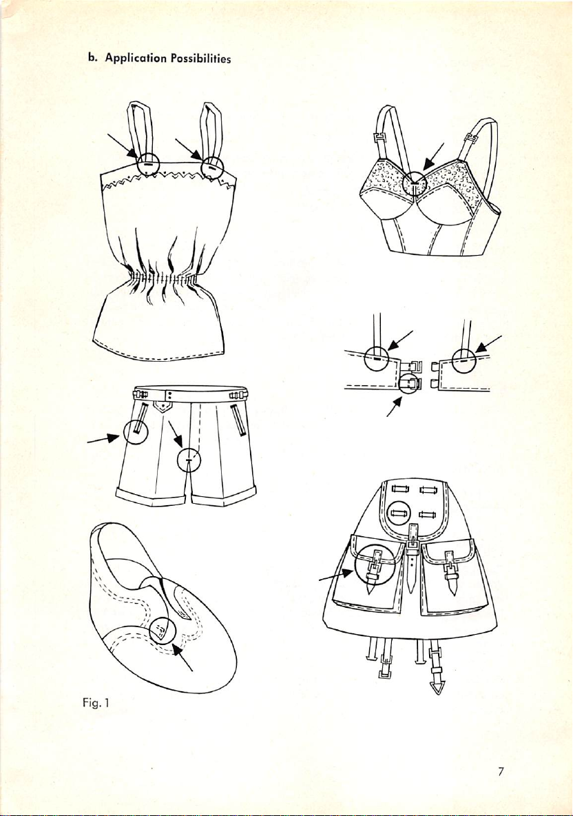
b. Application Possibilities
Fig. 1
Page 10
2.
Operation
a. Efficiency Rating
The output of on automatic bartacker is determined by the following factors:
(1)
the number of stitches
(2)
the
handling
times
per
involved
tack,
in a
given
operation
(which,inturn,
are de
termined by the size and bulkineess of the workpiece),
(3)
the quality of material
(4}
the handy arrangement of the work, and
(5)
the
speed
of the machine.
The
Pfaff
3334
automatic
21, 24, 28,
32, 36,
42,
contained in the Subclass Catalogue (Form No.
lity
of this efficient
and
thread,
48,
bartacker
56,
and 72
can
stitches
machine.Inspecial
be
fittedtomoke
per
tack.
The
tack
10080)
illustrate the versati
coses,
it may be advisable to sub
7, 9, 14, 16, 18,
design
diagrams
mita sample of the moterial to be sewn as wellas a specimen of the finished
work
eithertothe
Pfaff industrial
Kaiserslautern
sewing
machine
BranchofG.M.
representative.
Pfaff
AGorthe
nearest
b. Mode of
Operation
While both the length and width of a bartack con be varied within certain
limitsbysimply
adjusting a lever, its shape as well as the number of
stitch
es it comprises can be varied only by exchanging the feed cam.Inmany
instances, the worm gear assembly and the knife cam must be exchanged
in
addition.
The entire sewing action, including the stopping of the
automatically.
The machine is equipped with two cams which ore corried on a joint trans
verse
shaftoneither
sideofthe
machine
arm.
machine,
is controlled
The right, or feed, cam has two pattern-forming grooves, one on each side.
While the groove on its outside face controls the crosswise feed
motion,
the lengthwise feed motion emanates from the groove on its inside face.
The feed cam, in addition, carries
one
or several stop tripping segments as
well as one or several thread nipper tripping segments. Whereas the former
serve to stop the machine at the completion of a sewing cycle, the latter
actuate
The number of stop tripping segments and thread nipper tripping segments
the
thread
nipper.
provided on the rim of the feed cam depends on the number of tacks pro
duced
per
cam revolution.
Page 11
The left,or knife, cam operates the needle and bobbin thread
knives.
As the knives swing forward from the inoperative to the stand-by position,
a sufficient
whichtostart
amountofthread
the
next
tack.
is pulled from the spool
and
the bobbin with
As the machine makes the last stitch of the tack, the
couses the lower, or main, tension to be
releasedsothat
groove
in the knife cam
the
last
stitch knot
is pulled ino the material.
The main tension will not by reactivated until the machine, depending on the
subclass, has completed
three
to four stitches
after
starting a new tack. In
this way, puckering of the fabric is successfully eliminated. This is particularly
important for stitching
The machine is
delicate
started
the stop motion lever to swing back
interlocked.
The locking lever prevents the
clamp
while the machine is in
knivestotrim
By the
roised.
When
the
threads.
same
token, the machine
the machine is
started,
fabrics or sewing with long stitches.
by depressing the right treadle. This action causes
and
the tripping
operator
operation
from inadvertently raising the work
since this action would cause the
cannotbestarted
and
locking levers to be
while the work clamp is
the driving belt is shifted from the idler to the
driving pulley and, conversely, when the machine stops, it is returned from
the driving to the idler pulley.
All the
operator
has to do to start the sewing cycle is to press down the right
treadle. After the machine has stopped automatically, she raises the work
clompbydepressing
the
left
treadle.
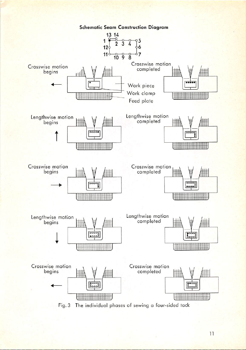
c. Sewing
The work is held between the work clamp
ed
after
Cycle
each stitch to form the
and
predetermined
the feed
plate
andisadvanc
tack design. This design is
produced by moving the material up and across the machine bed as the
needle moves up and down. Fig. 3 illustrates the sewing cycle of a rectang
ular
tock.
When the machine has been started by depressing the right treadle, the
needle
enters
the
fobric
for
the
first
stitch.
After
the
first
stitch
has
been
completed and the needle has risen clear of the fabric again, the work is
moved across the machine bed the predetermined distance between stitches.
This cycle is
repeated
until the tack is completed.
Page 12
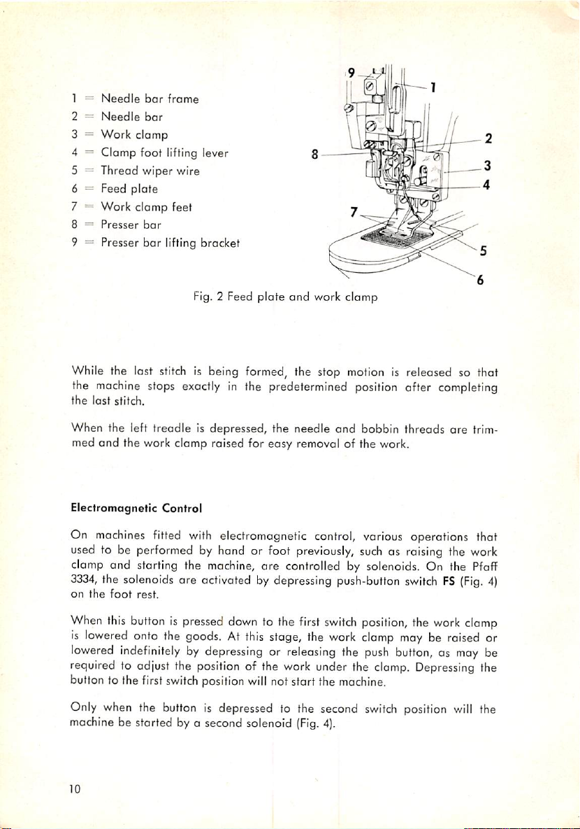
1 ==
Needle
2 =
Needle
3 =
Work
4 = Clamp foot lifting lever
5 = Thread wiper wire
6 = Feed plote
7 = Work clomp feet
8 =
Presser
9 — Presser bar lifting bracket
bar
bar
clamp
bar
frame
Fig. 2 Feed
While the last
the
machine
the
last
stitch.
When the left treadle is depressed, the needle
med and the work clomp raised for easy removal of the work.
Electromagnetic Control
stitch
stops
is being
exactly
plate
and
work
formed,
the stop
in the predetermined
clamp
motion
position
and
bobbin threads
is released so that
after
completing
are
trim
On machines fitted with electromagnetic control, various operations that
used to be performed by hand or foot
clomp and starting the
3334,
the
solenoids
on
the
foot
rest.
When
this
buttonispressed
is
lowered
lowered
onto the
indefinitelybydepressingorreleasing
machine,
ore
activatedbydepressing
down
goods.Atthis
previously,
suchasraising
the work
are controlled by solenoids. On the
to the
first
stage, the
push-button
switch
position,
work
clamp
the
switchFS(Fig.
mayberaised
push
button,asmay
the
work
Pfoff
clamp
or
be
required to odjust the position of the work under the clamp. Depressing the
button to the first switchposition will not start the machine.
4)
Only
when
the
button
is depressed to the second
machine be storted by a second solenoid
10
(Fig.
4).
switch
position
will
the
Page 13
Crosswise
motion
begins
Schematic Seam Construction
13
U
11<^^2r-2-^7
10
9 8
Crosswise
completed
Work
Work
clomp
Feed
Diagram
motion
piece
plate
Lengthwise motion
begins
Crosswise
motion
begins
Lengthwise motion
begins
Crosswise
motion
begins
Fig.3 The individual phases of sewing a four-sided tack
Lengthwise motion
completed
Crosswise
motion
completed
Lengthwise motion
completed
Crosswise
motion
completed
1
—1—1
lall
iiaHiiiH;HiK|^88|i88s
g
11
Page 14
12
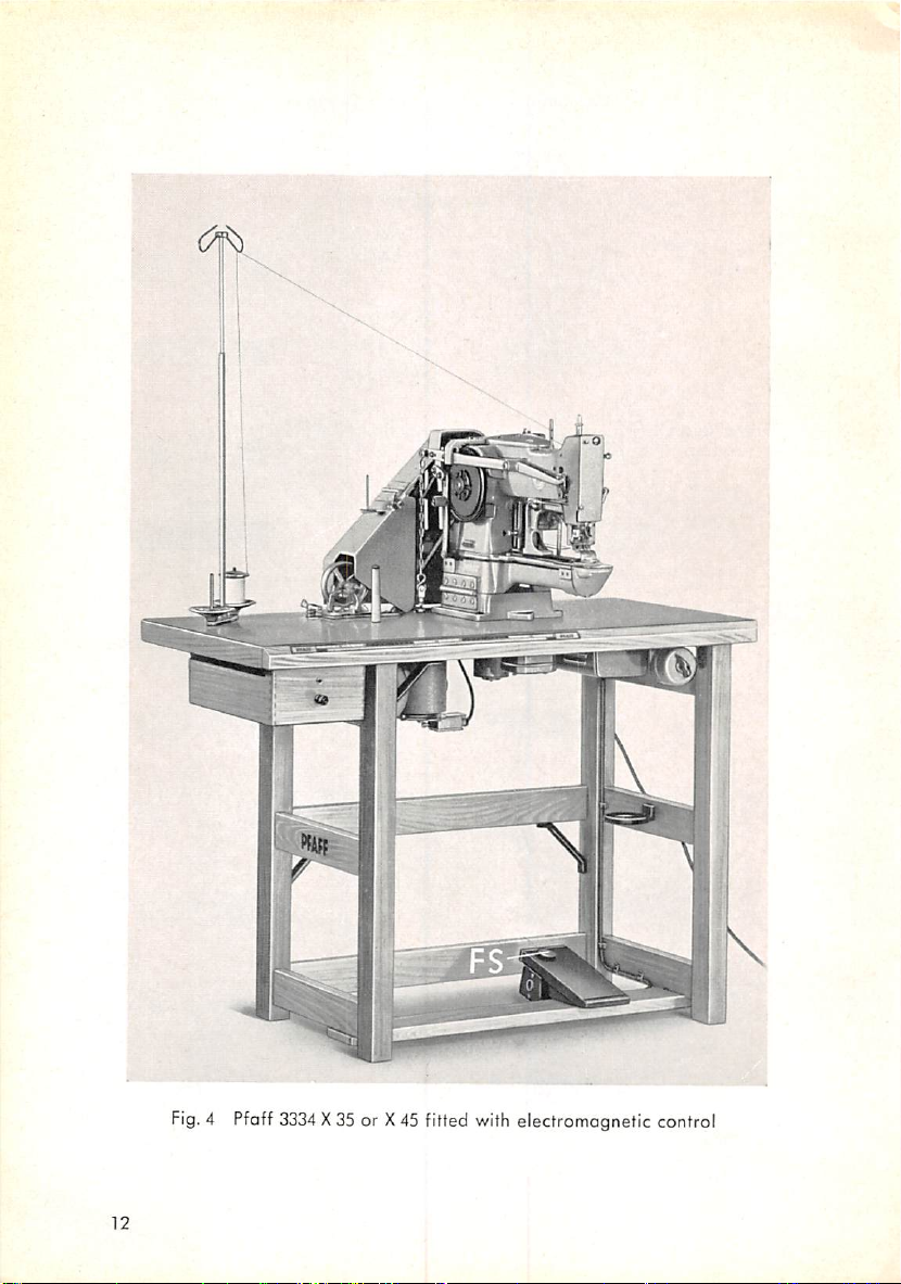
Fig.4Pfaff
3334
X35or X45fitted
with
electromagnetic control
Page 15
3.
Mechanical
Setup
From the foregoing description of the sewing action of a bortocker it is evident
that this machine must incorporate the following essential mechanisms, in
addition
to the shuttle
and
needle
bar
drive mechanisms found in
any
ordinary
sewing machine:
(1)
a special feed
termined
(2)
an automatic stop control which stops the machine as soon as the predeter
mined number of stitches
direction
mechanism
offer
each
which
advances the workpiece in the prede
stitch,
have
been
mode
and
the take-up lever has
almost reached the highest point of its stroke, and
(3)
a trimming mechanism whichsevers the needle and bobbin threads.
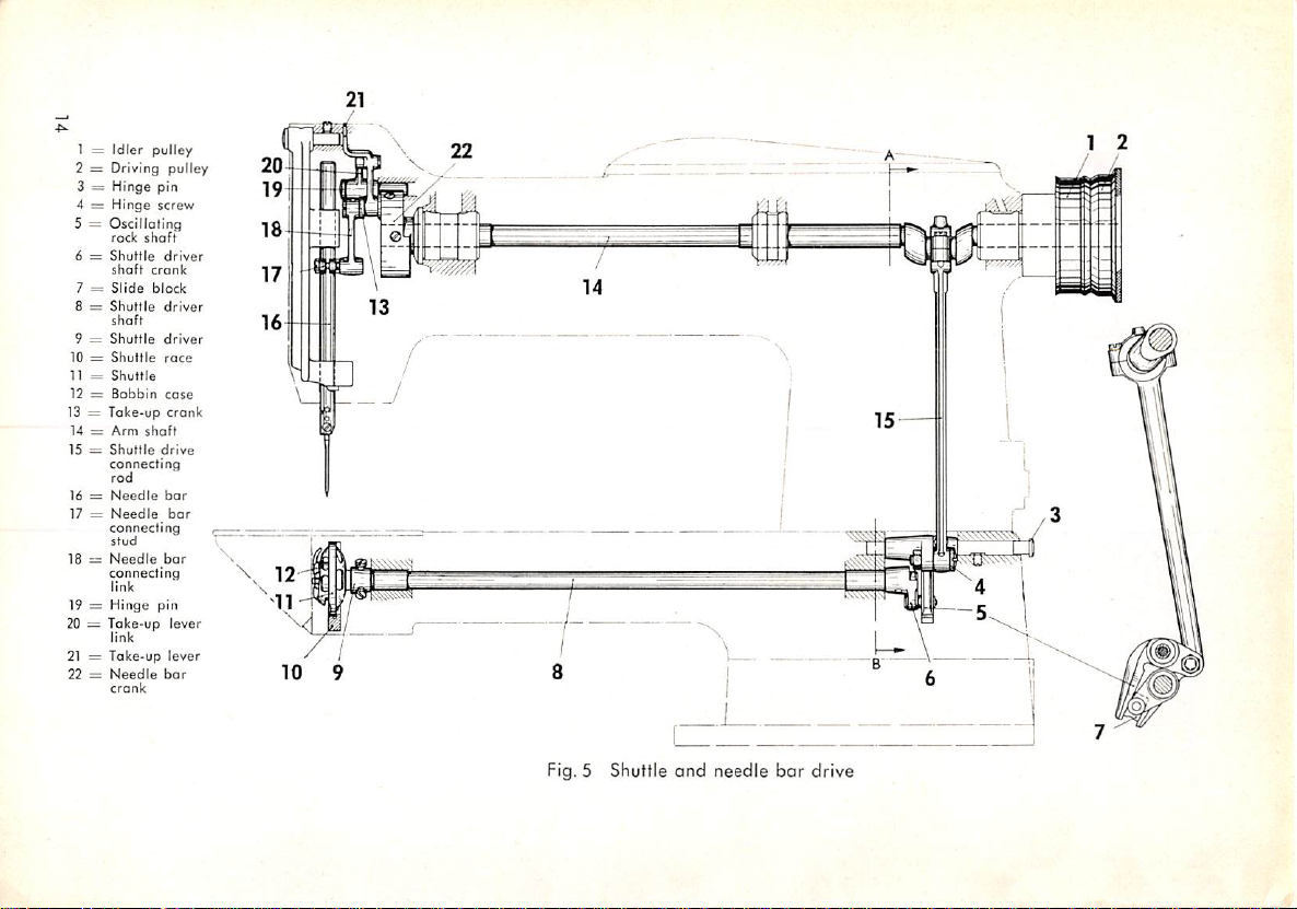
a.
Shuttle
and
Needle
Bar
Drive
The shuttle driving motion is derived from the cranked arm shaft and trans
mitted to the shuttle via a connecting rod, an oscillating rock shaft, a crank
with slide block, end the shuttle driver shaft. This mechanical setup produces
the oscillating motion required for this type of shuttle.
The needle
the needle
b.
Feed
bar
is moved up and down by means of the needle
bar
connecting link.
Motion
bar
crank and
The feed motion lengthwise and across the machine bed is controlled by
two pattern-forming grooves, one on either face of the feed cam.
Whenever the material is to be moved in a stroight line lengthwise or across
the machine bed, this motion is controlled by only one of these grooves.
The feed motions emanating from both grooves
are
combined to produce
circular, triangular or other tacks whose sides extend at on angle to the true
lengthwise or crosswise direction of feed.
The groove on the outside face of the feed cam controls the feed motion
crosswise of
the top end of the feed across regulator
and
transforms the throws
the
machine
bed.Asthe
emanating
feed
cam
revolves, o
(Figs.
6 &7}rides in this groove
roller
located
from its curvature into a reciprocating
motion which is transmitted to both the feed plate carrier bar and the work
clomp by means of a ball joint connection. The amount of motion across
the machine bed can be adjusted by changing the position of the ball joint
connectioninthe
slot of
the
feed
across
regulotor.
at
13
Page 16
1 =
Idler
2 = Driving
3 =
Hinge
4 =
Hinge
5 =
Oscillating
rock
6 =
Shuttle
shaft
7 =
Slide
8 =
Shuttle
shoft
9 =
Shuttle
10 =
Shuttle
11 =
Shuttle
12 =
Bobbin
13 =
Take-up
14 =
Arm
15 =
Shuttle
connecting
rod
16 =
Needle
17 =
Needle
connecting
stud
18=Needle
connecting
link
19 =
Hinge
20 = Take-up
link
21 = Take-up
22 =
Needle
crank
pulley
shaft
crank
block
shaft
pulley
pin
screw
driver
driver
driver
race
case
crank
drive
bar
bar
bar
pin
lever
lever
bar
nsi
1 4 1
—
'-^1
\ 1
1
6 ;
1
Fig. 5 Shuttle
and
needle
bar
drive
Page 17
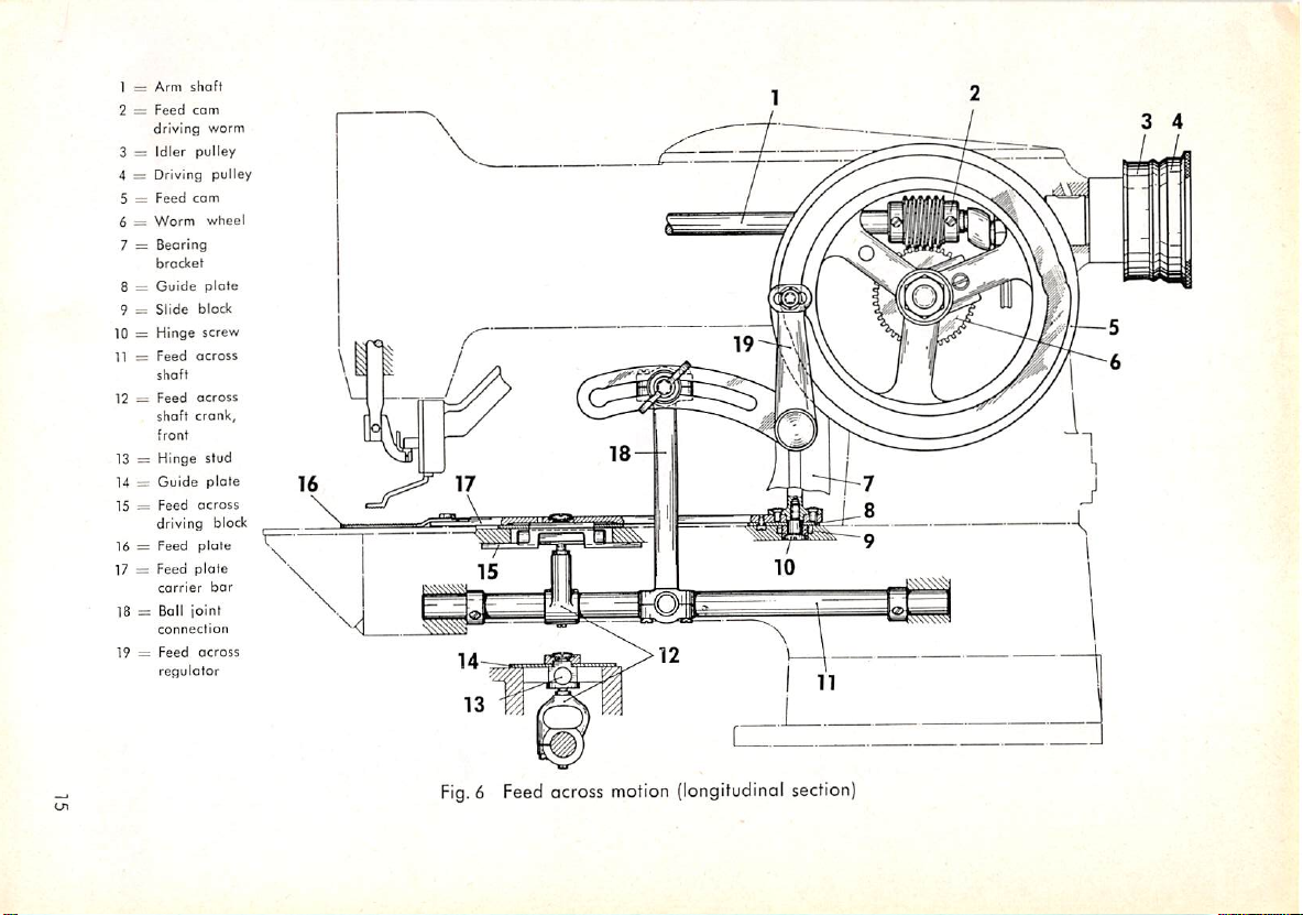
1 =
Arm
shaft
2 =
Feed
cam
driving
worm
3 =
Idler
pulley
4 = Driving pulley
5 =
Feed
com
6 —
Worm
wheel
7 =
Bearing
bracket
8 =
Guide
plate
9 =
Slide
block
10 =
Hinge
screw
11 =
Feed
across
shaft
12 =
Feed
across
shaft
crank,
front
13 = Hinge stud
14 =
Guide
plate
15 =
Feed
across
driving block
plote
carrier
connection
Feed
regulator
plate
bar
across
16 = Feed
17 = Feed
18 = Ball joint
19 =
V
\
\ 1
\
V
\
Fig.6Feed
across
motion
(longitudinal
section)
Page 18
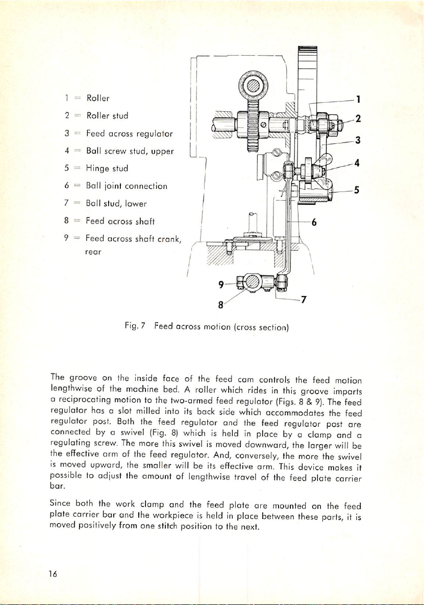
] =
2 =
Roller
Roller
stud
3 ~ Feed across
4 = Boll screw stud,
5 =
Hinge
6 = Ball joint connection
7 = Boll stud,
8 =
Feed
9 = Feed across shaft crank,
rear
stud
across
regulator
lower
shaft
Fig.7Feed
The
groove
lengthwiseofthe
a
reciprocating
regulator has a slot
regulator
connectedbyo
regulating
the
effective
is
moved
possibletoadjust
bor.
on the
post.
screw.
armofthe
upward,
inside
machine
motiontothe
milled
Both
the
swivel
The
more
the smaller
the
amountoflengthwise
upper
across
motion
(cross
section)
face
of the
feed
cam
controls
bed.Aroller
fwo-ormed
into
its
feed
regulator
back
which
feed
side
and
ridesinthis
regulator
which
the
(Figs.8&9).
accommodates the feed
feed
regulator
(Fig.8)whichisheldinplacebya
this
swivelismoved
feed
regulator.
willbeits
And,
downward,
conversely,
effective
travelofthe
orm.
the
This
feed
the feed
groove
clamp
the
larger
more
device
plate
imparts
The
post
will
the
makes
carrier
motion
feed
are
and
be
swivel
a
it
Since
both
the
plate
carrier
bor
moved positively
16
work
and
from
clomp
and the feed plate are
the
workpieceisheldinplace
one
stitch
position to the next.
mounted
between
on the feed
these
parts,itis
Page 19
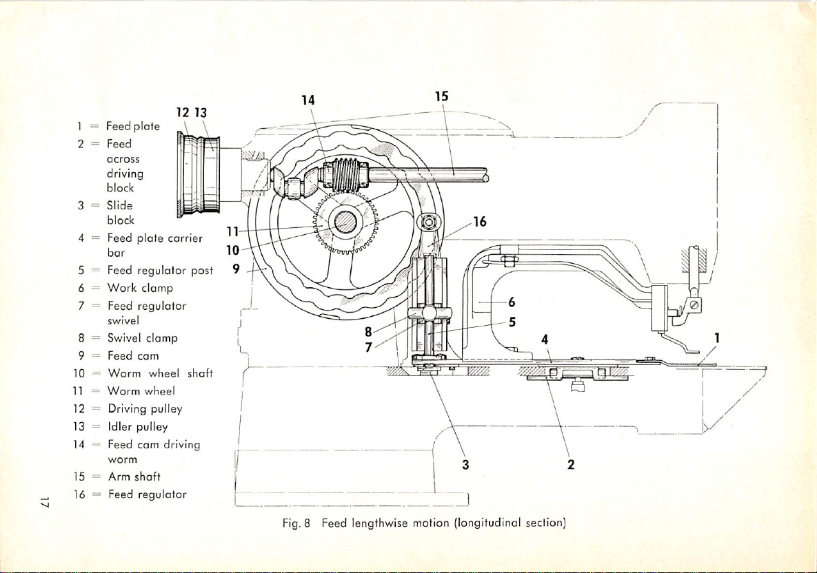
1 = Feed
2 =
plate
Feed
across
driving
block
3 =
Slide
block
4 =
Feed
plate
carrier
bar
5 = Feed regulator post
6 = Work
clamp
7 = Feed regulator
swivel
8 = Swivel
9 =
10=Worm
11 =
Feed
Worm
clamp
cam
wtieel
wheel
12 = Driving pulley
13
Idler pulley
Feed cam driving
14
worm
Arm
15
16
shaft
Feed regulotor
Fig.
8 Feed lengthwise motion (longitudinal section)
Page 20
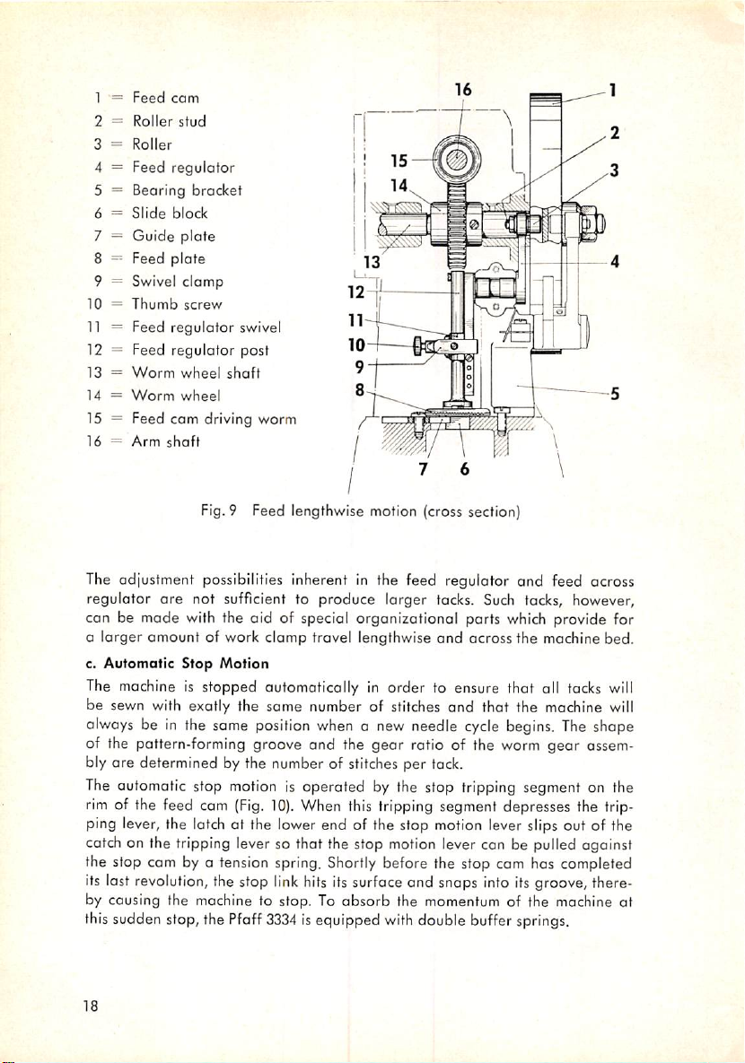
1 —
Feed
cam
2 =
Roller
stud
3 =
Roller
4 = Feed regulotor
5 = Bearing bracket
6 =
Slide
block
7 =
Guide
plate
8 ~ Feed plate
9 = Swivel
10 =
11
= Feed regulator swivel
12 =
13=Worm
14=Worm
Thumb
Feed
clamp
screw
regulator
wheel
wheel
post
shaft
15 = Feed cam driving worm
16 =
Arm
shaft
Fig.9 Feed lengthwise motion (cross section)
The adjustment possibilities inherent in the feed regulator and feed across
regulator ore not sufficient to produce larger tacks. Such tacks, however,
can be made with the aid of special organizational parts
which
provide for
a larger amount of work clomp travel lengthwise and ocross the machine bed.
c.
Automatic
Stop
Motion
The machine is stopped automatically in order to ensure that all tacks will
be sewn with exatly the some number of stitches and that the machine will
always
be in the same
position
whenanew
needle
cycle
begins.
The
shape
of the pattern-forming groove and the gear ratio of the worm gear ossem-
bly are determined by the number of stitches per tack.
The automatic stop
rim of the feed cam
motion
(Fig.
is operated by the stop tripping segment on the
10).
When this tripping segment depresses the trip
ping lever, the latch at the lower end of the stop motion lever slips out of the
catch on the tripping lever so that the stop
motion
lever can be pulled against
the stop com by a tension spring. Shortly before the stop com has completed
its last revolution, the stop link hits its surface and snaps into its groove, there
by causing the machine to stop. To
thissudden stop, the Pfaff
3334
absorb
isequipped
the momentum of the machine at
with
double buffer springs.
18
Page 21
t.
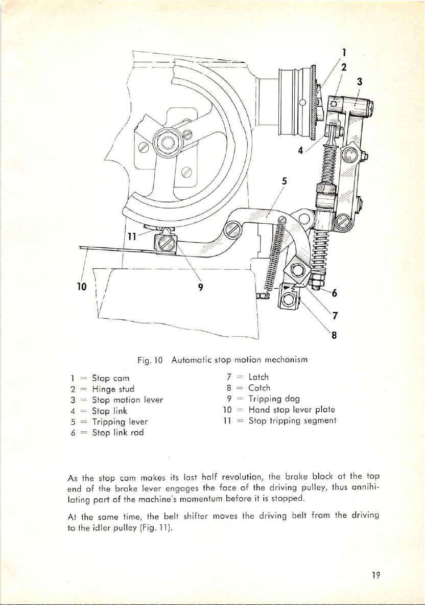
Fig.10 Automatic stop motion mechanism
1 =
Stop
cam
2 = Hinge stud
3 = Stop motion lever
4 = Stop link
5 = Tripping lever
6 = Stop link rod
7 =
Latch
8 =
Catch
9 = Tripping dog
10 = Hand stop lever plate
11 =
Stop
tripping
segment
As the stop cam
end of the broke lever engages the face of the
lating port of the
makes
machine's
its last half
momentum
revolution,
the broke
driving
before it isstopped.
At the same time, the belt shifter moves the driving belt
to the idler pulley (Fig. 11).
block
pulley,
from
at the top
thus
annihi
the driving
19
Page 22
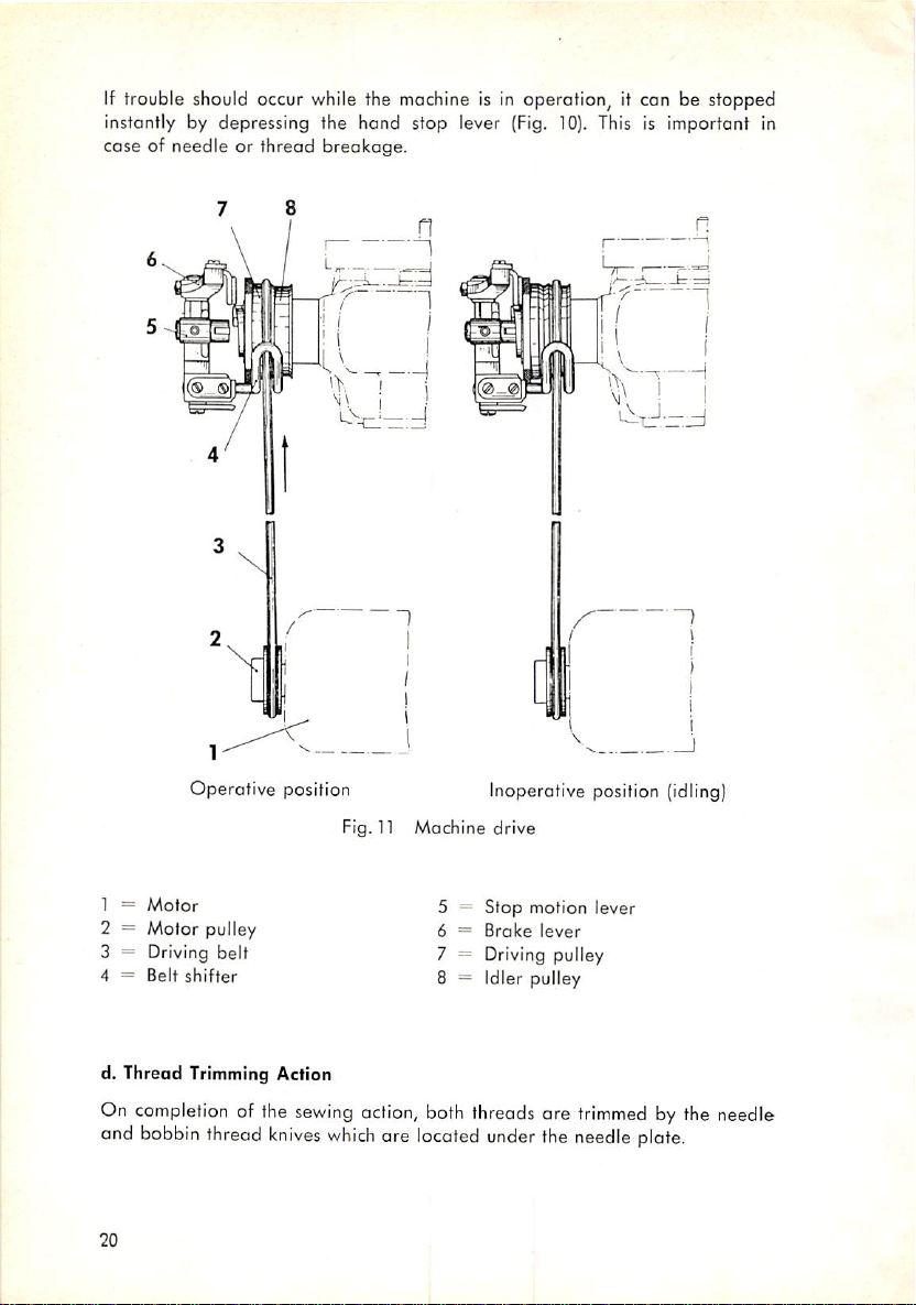
If trouble should occur while the machine is in operation, it can be stopped
instantly by depressing the hand stop lever (Fig. 10). This is important in
case of needle or thread breakage.
Operative
1 =
Motor
2 = Motor pulley
3 = Driving belt
4 =
Belt
shifter
d.
Thread
On
and
20
Trimming Action
completion
bobbin
thread
of the
knives
position
sewing
which
Fig. n
action,
Machine
5 -
6 =
7 = Driving pulley
8 = Idler pulley
both
threads
are
located
Inoperotive
drive
Stop
motion
Broke
lever
are
under
the
position
lever
trimmed
needle
(idling)
by the needle
plate.
Page 23
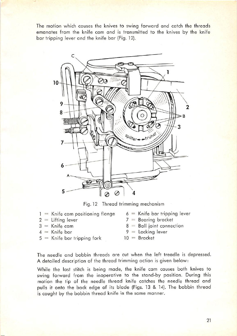
The motion which causes the knives to swing forward and catch the threads
emanates from the knife cam
bar
tripping lever
and
the knife
and
is transmitted to the knives by the knife
bar
(Fig. 12).
Fig.12 Thread trimming mechanism
bar
1 = Knife cam positioning flange 6
2 = Lifting lever 7
3 =
Knife
cam
4 =
Knife
bar
5 = Knife
The
needle
bar
tripping fork 10
and
bobbin
threads
are
Knife
Bearing bracket
Ball joint connection
8
Locking lever
9
Bracket
cut when the left
tripping lever
treadleisdepressed.
A detailed description of the thread trimming action is given below:
While the last stitch is being made, the knife cam causes both knives to
swing
forward from the inoperative to the stand-by position.
motion
pulls
the tip of the needle thread knife catches the needle thread and
it onto the
back
edge of
its
blade
(Figs.
13 &
14).
The
During
bobbin
this
thread
Is caught by the bobbin thread knife in the same manner.
21
Page 24
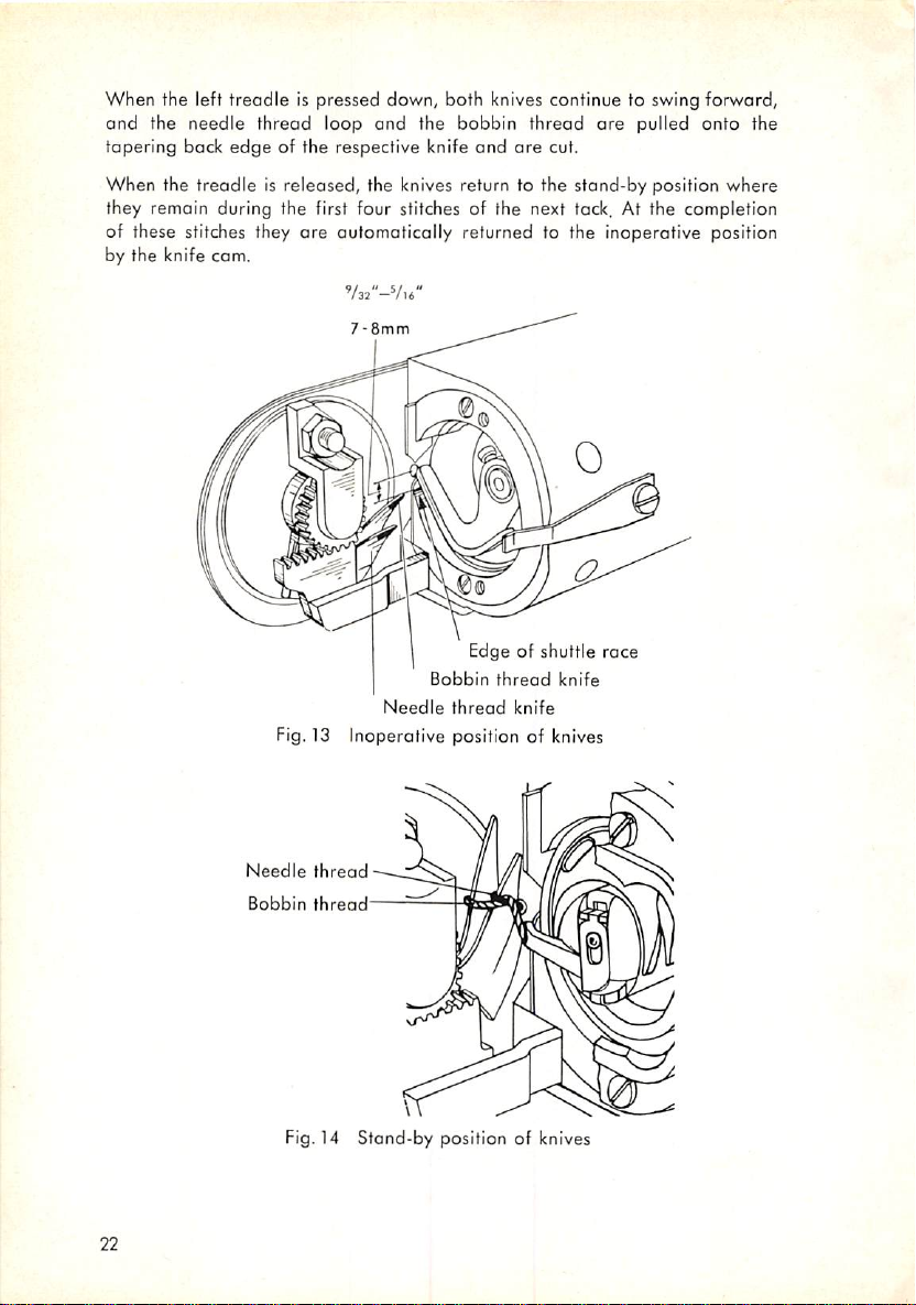
When the left treadle is pressed down, both knives continue to swing forward,
and
the
needle
tapering back
thread
edge
loop
and
of the respective knife and
the
bobbin
thread
are
cut.
are
pulled
onto
the
When the treadle is released, the knives return to the stand-by position where
they remain during the first four stitches of the next tack. At the completion
are
of these stitches they
by the knife
cam.
automatically returned to the inoperative position
'/32"-Vl6"
7-8mm
Needle
Edge of
Bobbin
thread
thread
knife
shuttle
knife
race
Fig. 13 Inoperotive position of knives
Needle
22
Bobbin
thread
thread
Fig. 14
Stand-by
position of knives
Page 25
18 19
20
21
63
22
62
23 24
58
61
60
57
56
55
54
53
52
51
50
49
0
29
25
26 27 28
30
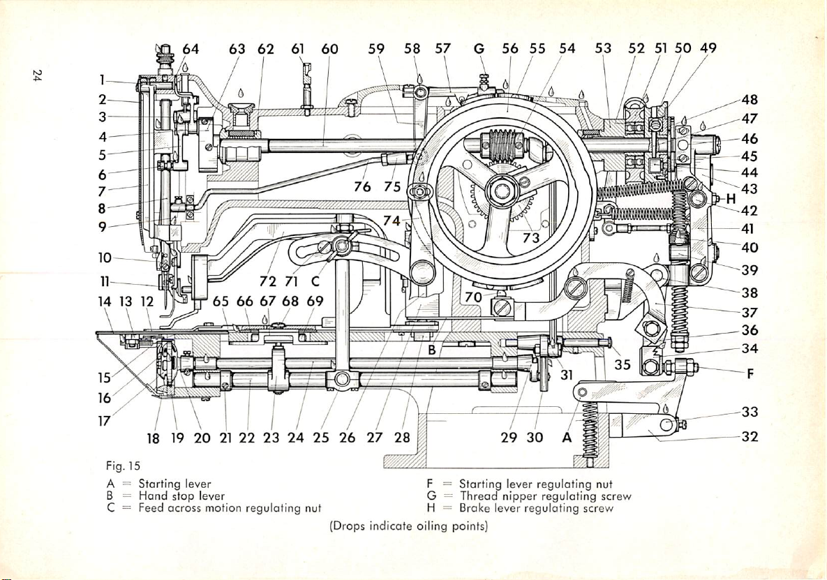
Fig. 15
A = Starting lever F = Starting lever regulating nut
B = Hand stop lever G = Thread
nipper
regulating screw
C = Feed across motion regulating nut H = Brake lever regulating screw
(Drops indicate oiling points]
Page 26

-
1
Hinge
stud
2 = Face
=
3
4
:
5
=
6
=
7
8 =
=
9
=
10
11
=
12
=
13
=
14
=:
15
16
17
—
18
—
19
=
20
21=Set
22
=
23
=
=
24
=
25
plate
Take-up
Take-up
Needle
Needle
Needle
Needle
lever link
crank
bar
connecting link
bar
connecting
bar
frame
bar
Thread nipper rod extension
Thread
Thread
Feed
nipper
wiper
plate
Thread trimming mechanism
Needle
Knife
Bobbin
Shuttle
Shuttle
Shuttle
Shuttle
Feed
Feed
Shuttle
collar
across
across
bar
race
race
driver
driver
plate
case
ring
shaft
shaft
Ball joint connection
lever
wire
shaft
crank,
stud
front
Bearing bracket
26
-
27
= Feed
=
28
=
29
30
=
31
32
= Bearing bracket
33
=
=
34
35
=
36
37
38
= Bearing bracket
-
39
=
40
=
41
=
42
43
=
44
=
45
46
=
47
=
48
49
=
50
regulator
Slide
block
Shuttle
driver
Oscillating
rock
Shuttle drive connecting rod
Hinge
stud
Stop
motion
Oscillating
rock
Tripping lever latch
-
Tripping lever
Hinge
stud
Felt
washer
Brake
lever
Hinge
stud
Stop
motion lever
Check
block
Brake
•
block
Brake regulating bracket
Positioning pin
Stop
com
Stop
com
spring
Driving pulley
shaft
lever
shaft
catch
shaft
crank
hinge
pin
51 =
52
53
54
55
56
57
58
59
60
61
62
63
64
65
66
67
68
69
70
71
72
73
74
75
76
=
=
=
_
=
=
=
=
=
=
=
•
Thread
Arm
nipper
shaft
w/ position pin
hinge stud
Page 27
55
54
53 52
51
50
49
48 47 46
45
44
15
16
43
17
62
61
58
18 19
59.60
20
40
39
21
22
23
24
25
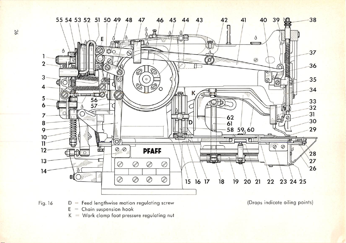
Fig.16 D = Feed lengthwise motion regulating screw
E = Chain suspension hook
Work
clomp
foot
K =
pressure reguloting nut
(Drops indicate oiling points)
Page 28

1
End
screw
=
2
Stop
motion
connection
w/circiip
bar
tripping
spring
bar
tripping fork
bracket
plate
plate
regulator
across
shaft
across
shaft
across
shaft
lever
lever
post
crank,
crank,
=
=
3
Locking lever
4 Spring suspension bracket
:
5
Boll joint
=
6
Washer,
7 =
Hinge stud
=
8
Bearing bracket
=
9
Knife
=
10
Stop link rod
=
11
Pressure
_
12
Knife
—
13
Position
14
Starting lever
15
Guide
16
=
Guide
17
Feed
18
Feed
19
Feed
=
20
Feed
=
21
Driving stud
=
rear
front
22
Feed
=
plate
w/position
23
Position bracket, front
=
24
Shuttle
race
25
Cylinder arm
26
Cylinder
-
27
Knife
=
28
Thread
29
Work
=
30
Thread
=
31
Clamp
.
32
Work
=
33
Work
=
34
Presser
35
Presser
36
Lifting
=
37
Presser
=
38
Pressure regulating screw
=
39
Oil
40
Lifting bracket
=
41
Lifting lever
arm
bar
trimming mechanism
clamp
wiper wire
foot
clamp
clamp
bar
bar
brocket
bar
tube
corrier bar.
pin
ring
cap
spring
cap
foot
lifting lever
foot lifting stud
face
plate
lifting bracket
link
spring
guide
42
=
Hinge
stud
43
Top
cover
=
=
44
Thread nipper hinge stud
45
= Knife cam positioning flange.
adjustable
=
46
Knife
cam
=
47
Lifting lever
48
Ball joint
=
49
Lifting lever
=
50
Bracket
51
Belt
=
52
= Idler pulley
53
=
54
55
56
57
58
=
59
=
60
61 Ball joint connection
62
shifter
Driving pulley
=
Stop
Hinge
Bracket
=
Bearing bracket
—
Feed
Work
Pressure spring
Swivel
guide
connection
extension
com
stud
regulator
clamp
clamp
Page 29
37 36
32
31
30
29
28
27 26
25
24
23 22
12
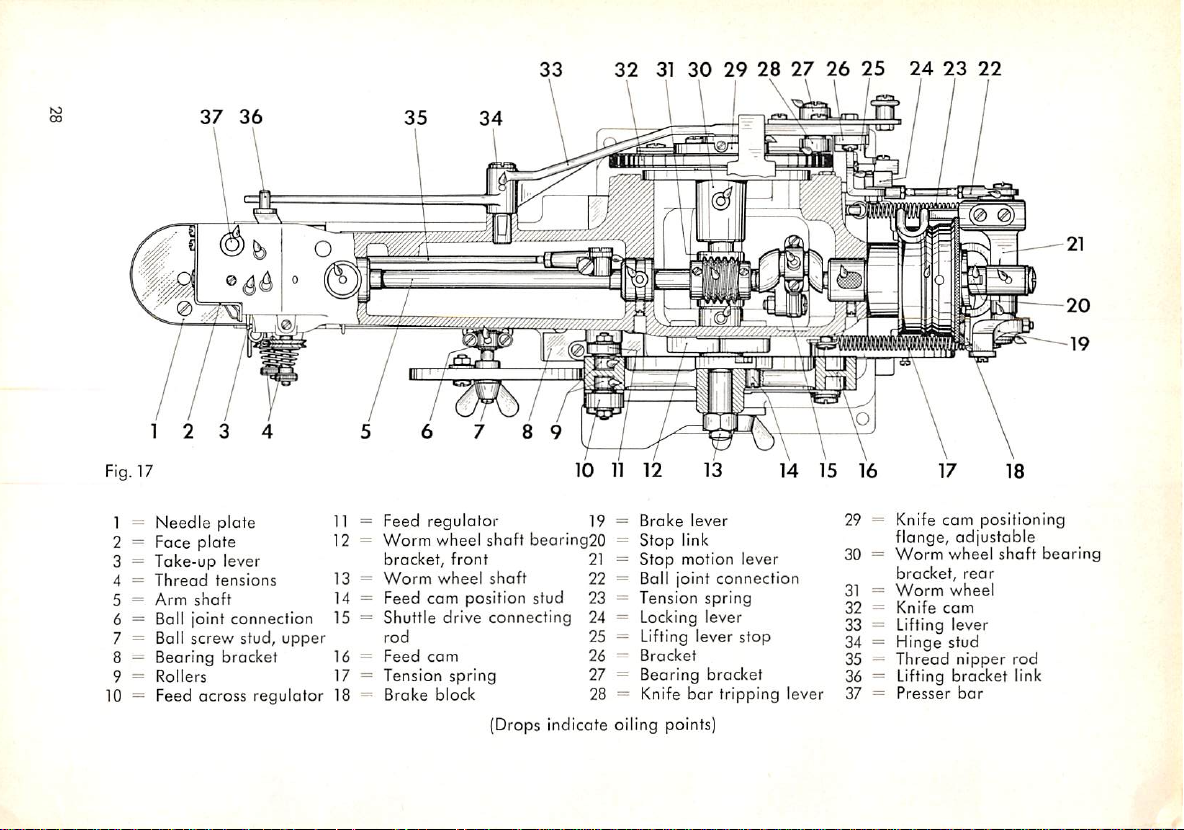
Fig. 17
1 =
Needle
2 = Face
3 =
Take-up
4 =
Thread
5 =
Arm
6 = Ball joint
7 = Ball screw stud,
8 — Bearing brocket 16 =
9 =
Rollers
10 = Feed across
3 4
plate
plate
tensions
shaft
lever
connection
upper
regulator
Feed
11 =
12 =
13 =
14 =
15 =
17
18 =
=
regulator
Worm
wheel
bracket,
Worm
shaft
front
wheel
Feed cam position stud 23
Shuttle
drive
rod
Feed
Tension
Brake
cam
connecting
spring
block
shaft
10
bearing20
11
12
19
Broke
Stop
21
Stop motion lever
22
Ball joint
Tension
Locking lever
24
Lifting lever stop
25
Bracket
26
Bearing bracket
27
Knife
28
13
lever
link
connection
spring
bar
tripping lever
14
15
{Drops indicate oiling points)
16 17 18
29 = Knife
30 =
31 =
32=Knife
flange,
Worm
bracket,
Worm
cam
positioning
adjustable
wheel
rear
wheel
cam
shaft
33 = Lifting lever
34 = Hinge stud
35 —
Thread
nipper
rod
36 = Lifting bracket link
37=Presser
bar
bearing
Page 30
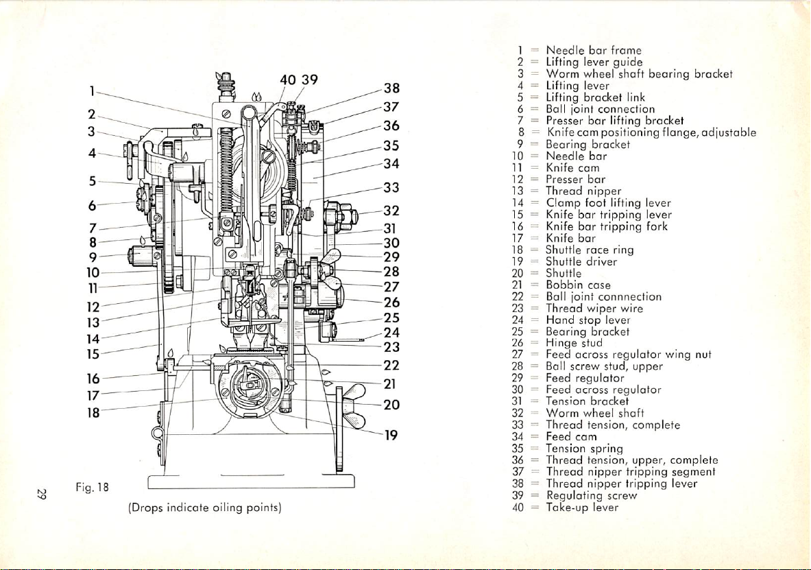
Fig. 18
(Drops indicate oiling points]
40
39
-^38
-37
-36
-35
"34
"33
-32
-31
30
-29
-28
-27
-26
-25
-24
-23
-22
-21
-20
-19
=
Needle
1
=
2
Lifting lever
=
3
Worm
-
Lifting lever
4
Lifting
5
----
6
Boll
7
Presser
=
8
=
9
Bearing
=
10
Needle
11
Knife
12
Presser
13
Thread
Clamp
14
--
15
Knife
--
16
Knife
=
17
Knife
—
18
Shuttle
19
Shuttle
20
Shuttle
-
21
Bobbin
22
Ball joint
23
Thread
24
Hand
Bearing
25
26
Hinge stud
-
27
Feed
=
28
Ball screw stud,
--
29
Feed
30
Feed
-
Tension
31
32
Worm
33
Thread tension, complete
=
34
Feed
=
Tension
35
=
36
Thread
37
Thread
-
38
Thread
=
39
Regulating screw
Take-up
40
bar
frame
guide
wheel
bracket
joint
connection
bar
lifting
Knifecam positioning flange,
bracket
bar
cam
bar
nipper
foot
lifting lever
bar
tripping lever
bar
tripping
bar
race
ring
driver
case
connnection
wiper
stop
lever
bracket
across
regulator
regulator
across
regulator
bracket
wheel
cam
spring
tension,
nipper
nipper
lever
shaft
bearing
link
bracket
fork
wire
wing nut
upper
shaft
upper,
tripping
complete
segment
tripping lever
bracket
adjustable
Page 31
B. Instructions
for
Repair
1. Disassembly
Strip the
intended. This rule applies particularly to dismantling the worm
bly.
plant.
machine
All
major repair and
only as far as is absolutely necessary for the repair job
conversion
jobs
should
be performed at the
gear
assem
Pfaff
It is advisable to strip complete ossemblies
and
reassembled as a unit. In
order
which
to avoid
can be easily disassembled
that
screws will be misplaced
or get lost, replace them in the screwholes immediately after the respective
port has been
removed,
if not
morked
previously,
spot the
positionofcranks
on shafts and the meshing teeth on both the worm and the worm wheel.
These
position
machine
To dismantle the machine completely, strip the ports in the following se
later.
marks
greatly facilitate the assembly and adjustment of the
quence (see illustrations on pages 24 through 29):
Needle, Work Clamp
Remove these ports first.
Stop Motion
Unscrew brake lever tension spring
Loosen
screw on stop motion lever hinge stud
Strip both the stop motion and broke levers, and dismantle
(22530).
Front
Ports
Turn out needle
on needle
bar
the machine cautiously. Dismantle presser bar
pressure regulating screw
foot lifting lever
take-up
Feed
lever.
Cam
Unscrew wing nut
(22394),
pull out feed across regulator
wheel shaft
loosen
(22009),
and
Face Plate
bar
frame set screw
frame hinge stud.
(392),
(22861).
(701578)
binding
and
Unscrew
on boll screw stud of boll joint connection
screw
pull the feed cam off this shaft.
(9624)
and boll joint connection
(11126),
(700073),
Pull
needle bar frame and hinge stud out of
presser bar lifting bracket
thread wiper wire
(700297)
(22017).
on bearing
Unscrew hexagon nut
and push out this stud.
and loosen set screw
(6523)
with presser bar spring,
(22037),
(22104),
bracket
(701638)
(22772).
locking
(700152)
and clamp
and strip
(21060),
on worm
lever
and
Knife
cam
Strip knife bar tripping lever
mantle
com
30
lifting
positioning
lever and knife cam (cautiously drive toper pin out of knife
flange).
(22239)
and lifting lever guide
(22004).
Dis
Page 32
Top Cover
Pull out thread nipper hinge stud
well as worm wheel shaft
Feed Regulator Bearing Bracket
Take both set screws
loosen thumb screw
Pull
and
Cylinder
and
Worm Wheel Shaft Bearing Bracket
rear
(700252)
(700293),
(22332),
bearing
out of feed regulator bearing bracket
and
and unscrew top cover
bracket
move swivel clamp
(22016).
(22467)
(22333)
(21060),
downward.
bearing bracket to the right and up, end strip feed plate carrier bar
feed
regulator
Bed Parts
post.
Unscrew needle plate and shuttle race ring. Take out shuttle, and strip
shuttle race. Cautiously drive pin out of shuttle driver shaft crank
pull out shuttle driver shaft. Dismantle feed across shaft
Arm
Parts
Strip
shuttle
crank ond worm, slacken set screws
(21195),
points
Worm
Loosen set screws im worm wheel,
bearing bracket
you drive out taper pin
drive connecting rod
(22059).
Loosen
(700150)
and cautiously drive out arm shaft, making sure its cranked portion
downward.
Wheel
Shaft
and
attach
(22016)
so that the worm wheel shaft
(1848).
Now
pull
worm wheel shaft out of
(22020).
set
screws
in arm shaft rear bushing
worm wheel shaft
will
(6568),
and
in needle bar
rear
not be bent when
machine.
2. Assembly
Examine
or replace damaged parts.
oil parts for wear before you assemble
Make
sure to
remove
them.
If necessary,
rework
burrs and dents on shafts
so as to ensure that gears, eccentrics, set collars and other parts can be
moved
are
on them
likely
eosily.
to cause
All
binding
shafts
and
must
be perfectly straight because bent shafts
noisy
running
of the
machine.Tofacilitate
subsequent adjustment, it is recommended to replace all parts in close
proximity to their previous positions.
Worm
Wheel
Shaft
Replace both the worm wheel and the worm wheel shaft. Again screw on
worm
wheel shaft rear bearing bracket
when you drive home taper pin
Arm
Ports
Replace
arm shaft
with
driving
(1848).
pulley
(22016)
(20658),
so that the shaft
arm shaft rear
will
not be bent
bushing
(21195)
and worm. Push needle bar crank onto arm shaft, and screw down. Rotate
arm
shaft
to make sure it revolves freely. Mesh worm
and
worm wheel
as
31
Page 33
in
accordance
with
position
marks.
Both
the
arm
ond
worm
wheel
shafts
must revolve freely, without having any end play. The only gears that may
have a scarcely perceptible amount of play
are
the worm and worm wheel.
Place machine on
be too noisy, correct this condition by setting the worm as close to the
worm wheel as possible
hove any
end
pulley as close to arm shaft
screws securely. Re-ream pin hole with a
taper
pin to pin driving pulley on arm shaft. Make sure the
stand
play, drive
and
test-run it. If the worm
and
relapping
taper
rear
both parts. If the
pin
(2056)
bearing as possible,
gear
arm
out
of the driving pulley, set
taper
reamer,
and
assembly should
shaft
should
and
tighten set
take
a thicker
taper
pin does
not protrude from the hub of the pulley, as this would interfere with the
proper functioning of the stop cam spring.
If a new arm shaft must be installed in the machine, drill the toper pin
hole in the driving pulley only
after
the
latter
has
been
mounted on the
shaft. The driving pulley is screwed onto the arm shaft only until the front
ports have been installed. Rotate the driving pulley on the arm shaft until
the groove in the stop com extends vertically. Check to see that the machine
stops when the ascending take-up lever has reached a position about
^Ua",
or 2.0 mm, below the highest point of its stroke. To make whatever adiust-
ment may be necessary, insert stop com spring, Novotex segment
and stop cam
Insert shuttle drive connecting rod
(20062)
into the driving pulley.
(22059)
and oscillating rock shaft
(20275),
(6674),
and check to see that both parts move freely without having any end ploy.
Mount thread nipper components in machine arm.
Front
Parts
Screw on needle plate, and odd take-up lever. Insert needle bor frame
with needle bar, and align so that needle is correctly centered in the needle
hole. Mount presser
Cylinder
Bed Ports
Insert feed plate carrier
to the feed plate carrier
without having ony lateral play. Screw feed across driving block
guide plate
parts
move
freely. Install
and rear cranks. Adjust the front crank so that driving stud
in the cutout of the feed across driving block when both feed motions
set on
zero.
Add shuttle driver
(22391)
bar
with guide, spring and pressure regulating screw.
bar
and
bearing bracket. Set guide plate as close
bar
as possible so that the latter moves freely
to feed plate carrier bar, making sure the attached
feed
across
shaft
with
set
shaft
with crank
collarsaswell as
(22025)
(6568).
front
is centered
and
are
Feed
Com
Attach feed cam,
and
tighten hexagon nut on worm wheel shaft. Make sure
the machine runs smoothly and the roller does not chafe
32
against
the bottom
Page 34
of
plate
l"he
pattern-forming groove. Add feed across regulator, and screw feed
onto
feed
plate
carrier
bar.
prevent
To
loosen the set screws in the
by hand. This action will cause the rollers to
grooves automatically.
Knife
Attach bearing bracket for knife
the rollers from becoming
Com
bearing
bar
wedged
bracket,
tripping lever
and
odopt
in the grooves,
turn the driving pulley
the best position in the
(22239).
Push knife cam
again
with positioning flange onto worm wheel shaft, pin down, and tighten set
screws securely. Install knife
of rack and pinion mesh. Mount lifting lever
bar
tripping lever by means of ball joint connection
Stop Motion
Attach stop motion lever, brake lever, tripping lever, and locking lever.
Other
Ports
Attach remaining parts while you adjust the machine, or
has
been
completed.
3. Adjustment
To focilitate the use of this manual, all adjustments discussed in the follow
ing chapter,
and
Check-Up
wherever
for instance, all adjustments pertaining to the shuttle
the heading
"Timing
the Shuttle and Setting the Needle Bar at Correct
bar
(22088),
making sure that spotted teeth
(22003)
and connect with knife
(22512).
feasible, hove been grouped by
will
after
adjustment
assemblies.
Thus,
be found under
Height". For best results, it is recommended to perform the adjustment
and check-up of a machine in the sequence given below.
Important
Always
size in accordance with the material to be sewn. Unless specified otherwise,
insert a new needle before you adjust a
machine.
Select the needle
the adjustments discussed below apply to all subclasses. Certain materials,
however, necessitate minor deviations from the standard settings given here.
a.
Timing
Insert a new needle,
the Shuttle and Settingthe Needle Barat CorrectHeight
and
screw on the needle plate. Loosen the set screw
in the needle bar frame, and adjust the latter so that the needle is centered
in the needle hole. (Needle plate inserts are available in various needle hole
sizes).
33
Page 35

(1)
Needle
Bar Rise
The amount of needle
mm. This means that the point of the shuttle should be opposite the center
bar
rise required to form the loop is
V35",
or 2.4
line of the needle when the letter has passed the lowest point of its stroke
V32".
and risen
as
viewed
rise can be set easily with the aid of
Make sure you turn the driving pulley counter-clockwise,
from
the
backofthe
machine.
gauge
The
correct
No. Z 70.67-2 (Fig.
amount
19}.
of
needle
bar
Fig. 19 Setting the
omountofneedle
bar
rise
To moke this adjustment, turn driving pulley to bring needle bar to its
lowest
the
shuttle
the
gouge
and the
gauge,
34
position.
and
When
the needle has reached the
should
bottom
be at
its
left
point of reversal. Slip both the clamp and
onto the
tighten the clamp screw. To moke sure the needle
needle
bar,
of the needle bar
positioning
frame.
the latter
Push
the
lowest
clamp
point of its
between
up against the
barisat
the
stroke,
clamp
the
Page 36
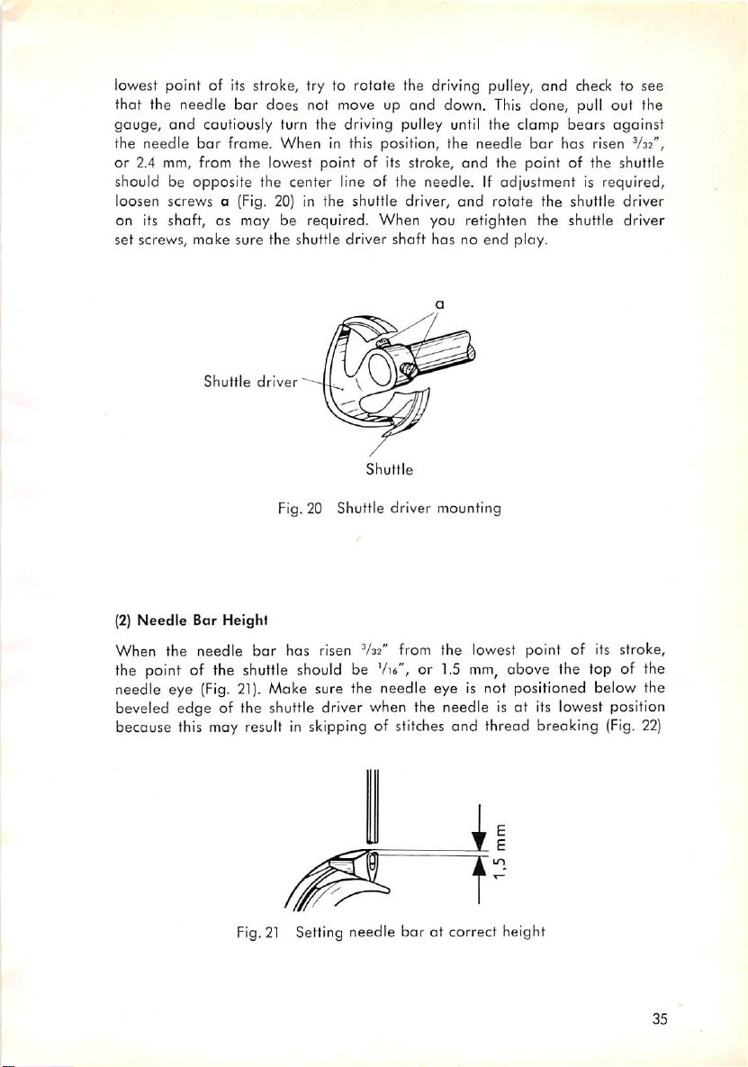
lowest point of its stroke, try to rotate the driving pulley,
and
check to see
that the needle bar does not move up and down. This done, pull out the
gauge,
the
or
should be
and
cautiously turn the driving pulley until the clomp
needle
bor
frame.
When
in this position,
2.4 mm, from the lowest point of its stroke,
opposite
the
center
line of the needle. If adjustment is required,
the
needle
bar
and
the point of the shuttle
bears
has
risen
against
V32",
loosen screws a (Fig. 20) in the shuttle driver, and rotate the shuttle driver
on its shaft, as may be required.
When
you retighten the shuttle driver
set screws, make sure the shuttle driver shaft has no end play.
Shuttle
driver
Shuttle
Fig.20 Shuttle driver mounting
(2)
Needle
When the needle
Bar Height
bar
has risen
V32"
from the lowest point of its stroke,
the point of the shuttle should be Vii", or 1.5 mm, above the top of the
(Fig.
21).
needle eye
beveled
edge
becouse this may result in skipping of stitches
Make sure the needle eye is not positioned below the
of the shuttle driver when the needle is at its lowest position
and
thread breaking (Fig. 22)
Fig.21Setting needle bar at correct height
35
Page 37

Fig.
22 Setting the needle bar at correct height
36
Page 38

To
adjust,
higheror
loosen
screw
lower,
as may be required
a on needle bar
(Fig.
connecting
22).
stud,
and set needle bar
(3)Setting
When the needle has risen
Needle
to Shuttle
V32"
should be a clearance of about
the point of the
shuttle.
This
settingispredeterminedbythe
shuttle race and cannot be changed
Shuttle
Needle
0,1
from the lowest point of its stroke, there
.004",or0.1
(Fig.
mm
23).
mm,
between the needle ond
position
of the
Fig. 23 Setting needle to shuttle
The only way adjustment can be made is by exchanging the shuttle race.
Shuttle races
.012",or0.1, 0.2
recent machines, this adjustment
thickness.
(4) Setting
order
In
are
Needle
to avoid
available
and
to Shuttle Driver
that
for this purpose which
0.3 mm,
the point of the shuttle hits the
thicker
than
canbemadebyadding
the
ore
standard
.004", .008"
shuttle
spacers
needle
race.
of varying
if the
letter
and
On
is deflected by hard spots in the material, the shuttle driver has been design
ed as a
needle
guide. The needle should
bear
lightly
against
the shuttle
driver when the point of the shuttle passes it. If adjustment is required,
bend the shuttle driver coutiously (Fig. 24).
37
Page 39

Needle
guide
Shuttle
Fig. 24 Setting
(5)
Clearance
The
clearance
to permit the heaviest
pass
through it freely. A
Between
gap
between
Shuttle
gradeofthread
normally will be sufficient for this purpose. To
and
Shuttle Driver
shuttle
clearance
needle
to shuttle driver
and
shuttle driver should be wide enough
used on this
of
obout
V64",
allow
used on this machine, it may be necessary to make this
or
0.6 to 0.7 mm,
wide.
driver
particular
machine to
or 0.4 to 0.5 mm,
heavier
gap
threads
about
to be
V32",
If adjustment is required, bend the driver fingers cautiously, making sure,
however,
top finger is positioned exactly
(Fig. 25).
1 =
2 = Shuttle driver top finger
3 =
4 = Shuttle driver bottom finger
5 =
that
the bottom finger
Clearance
V64",or0.4 to 0.5 mm
opposite
Shuttle
lines up with heel of shuttle
(must not
gap
center of neck
driver
contact
shuttle
race)
Shuttle
does
opposite
not
contact
the
the shuttle
center
of the shuttle neck
m
race
and
the
Fig. 25 Clearance gap between shuttle and shuttle driver
38
Page 40
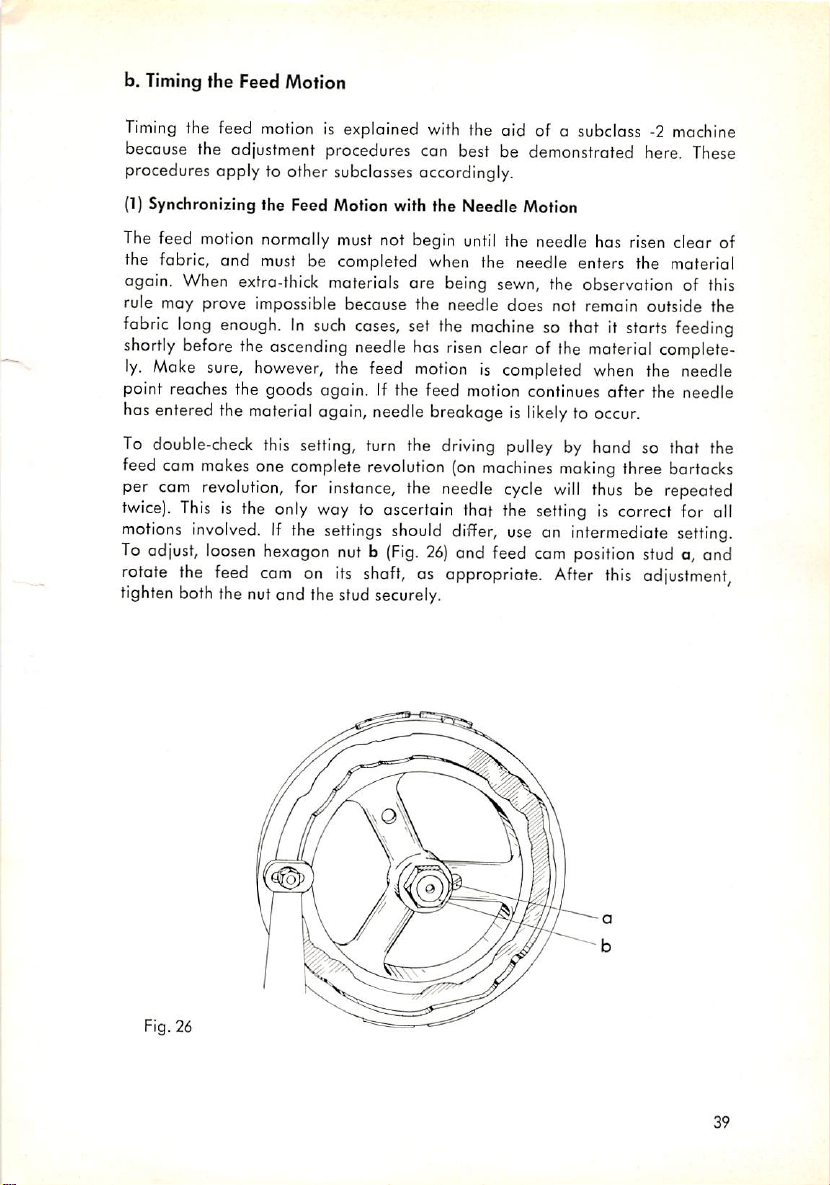
b.
Timing
the Feed Motion
Timing
procedures apply to other subclasses accordingly.
(1}
The feed motion normally must not begin
the fabric, and must be completed when the needle enters the materiel
again. When extra-thick materials are being sewn, the observation of this
rule may prove impossible because the needle does not remain outside the
fabric
shortly
ly.
point reaches the goods again. If the feed motion continues
has
To
feed
per
twice).
motions
To adjust,
rotate
tighten
the feed motion is explained with the aid of o subclass -2 machine
because the adjustment procedures can best be demonstrated here. These
Synchronizing the Feed Motion with the Needle Motion
until
the needle has risen clear of
long
enough.Insuch
before
the
Make
sure,
however,
entered
double-check
com
the
material
this setting, turn the
cam
makes
one
revolution,
This
is the only way to ascertain that the
involved.Ifthe
loosen
hexagon nut b
the
feed
cam
boththe nutand the
ascending
complete
for
again,
settings
on
cases,
set the
needle
has
risen
the feed
instance,
its
stud
motioniscompleted
needle
breakageislikelytooccur.
driving
revolution
should
(Fig.
(on
the needle
differ,
26)
and feed cam
shaft,asappropriate.
securely.
machine
so that it
clearofthe
pulley
by hond so that the
machines
cycle
making
will
setting
useanintermediate
position
After
starts
feeding
moterial
when
thus
is correct for all
complete
the needle
after
the needle
three
be repeated
bartacks
setting.
stud a, and
this
adjustment,
Fig. 26
39
Page 41
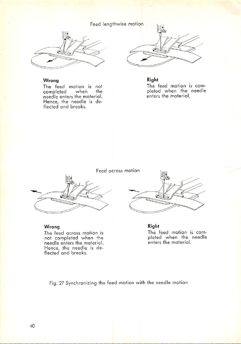
Feed lengthwise motion
Wrong
The
feed
motion
is
not
completed when the
needle
enters
the
Hence,
flected
the
and
needle
breaks.
material.
is de
Wrong
The
feed
across
motion
not completed when the
needle
enters
the
Hence,
flected
the
and
needle
breaks.
materiel.
is de
Feed
is
across
motion
Right
The
feed
motioniscom
pleted when the needle
enters
the
material.
Right
The
feed
pleted when the needle
enters
motioniscom
the
material.
Fig.
27 Synchronizing the feed motion with the needle motion
40
Page 42

(2)
Timingthe Feed Lengthwise Motion
When
the roller stud is positioned in the middle of the
in the feed
regulator
A in Fig. 28), the
elongated
screws a
as
appropriate.
hole in the work
and
b (Fig. 28),
and
needle
the swivel
must be centered in the feed
and
Wrong
clamp
move the
clampisat
its highest position (marked
feet. If adjustment is
bearing
bracket
forwardorbackward,
elongated
plate
needed,
hole
cutout or the
loosen
1 =
Feed
2 = Bearing
3 = Feed
4 =
Feed
5 =
Needle
6 =
Workpiece
7 = Adjust
8 =
Work
cam
bracket
plate
carrier
bar
plate
clomp
feet
Fig. 28 Timing the feed lengthwise motion
9 = Feed
10 =
Thumb
11 = Swivel
12=Thrust
13 = Feed
14 =
Feed
15=Roller
16 =
Pattern-forming
regulator
screw
clamp
washer
regulator
regulator
stud
post
swivel
groove
41
Page 43

When the swivel clamp is moved down to position B, the feed plate should
move the some distance from the middle both ways so that the needle will
hit neither the work clamp feet nor the feed plate. Adjustment can be
made by loosening nut c (Fig. 29) and moving the roller stud in the elongated
hole of the feed regulator, as may be appropriate.
Wrong
4'
« I
Wrong
42
Work
clamp feet
Adjust
Workpiece
Needle
Roller
stud
Right
Fig. 29 Timing the feed
6 = Feed
regulator
7 = Bearing bracket
8 = Thumb screw for adjusting
the feed lengthwise motion
9 =
Feed
plote
10 =
lengthwise
Feed
motion
carrier
plate
bar
Page 44
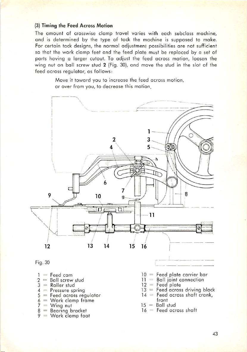
(3)
Timing the Feed Across Motion
The
amount
andisdetermined
For certain tack designs, the normal adjustment possibilities
of crosswise clamp travel varies with each subclass machine,
by the type of tack the machine is
supposed
are
not sufficient
to make.
so that the work clamp feet and the feed plate must be replaced by o set of
parts having a larger cutout. To
wing nut on ball screw stud 2 (Fig. 30),
across
feed
regulator, as follows:
Move it
toward
you to increase the feed across motion,
adjust
the
feed
across motion, loosen the
and
move the stud in the slot of the
or over from you, to decrease this motion.
Fig. 30
1 =
Feed
2 =
3 =
4 =
com
Ball
screw
Roller
Pressure
stud
stud
spring
5 = Feed across
6 =
Work
Wing
clamp
nut
7 =
8 = Beoring bracket
9 =
Work
clomp
regulator
frame
foot
10 = Feed plate carrier
11 = Ball joint
12 = Feed
13 =
Feed
14 =
Feed
front
15=Ball
16 =
Feed
plate
across
across
stud
across
connection
driving block
shaft
shaft
bar
crank,
43
Page 45
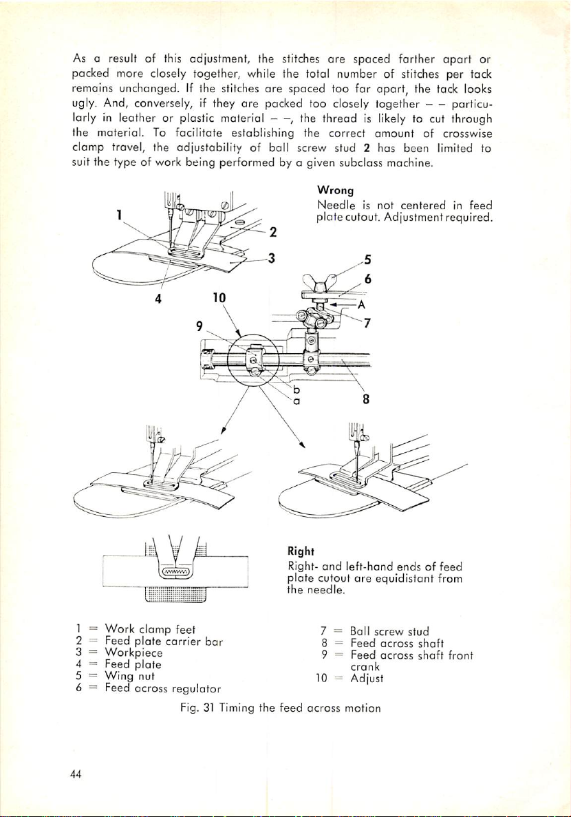
As a result of this adjustment, the stitches are spaced farther
apart
packed more closely together, while the total number of stitches per tack
remains
unchanged.
If the
stitches
are spaced too for opart, the
tack
looks
ugly. And, conversely, if they are packed too closely together particu
larly in leather or plastic material , the thread is
the material. To facilitate establishing the correct
likely
amount
to cut through
of crosswise
clamp travel, the adjustability of ball screw stud 2 has been limited to
suit the type of work being performed by a given subclass mochine.
Wrong
Needleisnot
platecutout. Adjustment required.
centered
in
feed
or
1 =
Work
clamp
2 =
3 =
Feed
Workpiece
plate
feet
carrier
4 = Feed plate
Wing
5 =
nut
6 = Feed across regulator
Fig. 31 Timing
44
bar
the
Right
Right-
plate
the
feed
and
left-hand
cutout
needle.
across
ore
7 =
Ball
8 =
Feed
9 =
Feed
crank
10 - Adjust
motion
endsoffeed
equidistant
screw
stud
across
shaft
across
shaft
from
front
Page 46
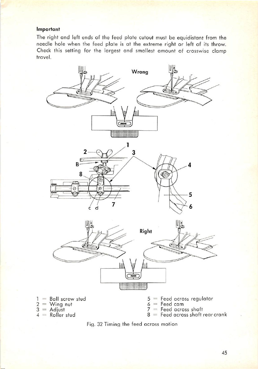
Important
The right
and
left ends of the feed plate cutout must be equidistant from the
needle hole when the feed plate is at the extreme right or left of its throw.
Check
this setting for the largest and smallest amount of crosswise clamp
travel.
Wrong
1 =
Ball
2 =
Wing
3 = Adjust
4 =
Roller
screw
nut
stud
stud
Fig. 32 Timing
the
5 = Feed across regulator
6 =
Feed
Feed
Feed
motion
com
across
across
feed
7 =
8 =
across
shaft
shaft
rear
crank
45
Page 47
To odjust, set the roller stud in the middle of the
feed
across
regulator
(Fig. 32). Loosen wing nut 5 (Fig. 31),
elongated
hole in the
and
move
boll screw stud 7 to its extreme left position in the slot of the feed across
regulator (marked A in Fig.
amount
the right-
of crosswise clamp travel. Turn the driving pulley,
and
left-hand ends of the feed plate cutout
31).
The machine is now set for the largest
and
check whether
are
equidistant from
the needle hole when the feed plate is at the extreme right or left of its
throw. To adjust, loosen screws a
and
b on the feed
across
shaft
front
crank and adjust the position of the feed plate, as appropriate.
Move ball screw stud 7 to the right in the slot of the feed across regulator
as f»f as it will go, thus setting the machine for the smallest
crosswise clomp travel.
the driving pulley, check to see
This
position is marked B in
that
the short tack side is centered within
Fig,
amount
32. As you turn
the long tack side produced with the previous setting. If adjustment is
required, loosen screws c and d on the feed across shaft rear crank, and
move the crank slightly to the right or left on the shaft until the correct
setting is obtained (Fig. 32).
Again set the machine for the largest amount of crosswise clamp travel,
and check whether the left- and right-hand ends of the feed plate cutout
are equidistant from the needle when the feed plate is at the extreme right
or left of its throw. If necessary, adjust as instructed obove.
Provided the adjustment hos been made conscientiously, tacks of all sizes
will be correctly centered in the feed plate cutout.
If the
small
tack
is positioned to the left of the center
line
of the large
tack,
move the feed across shaft rear crank slightly to the left. And, conversely,
if it is positioned too far to the right, move the crank slightly to the right.
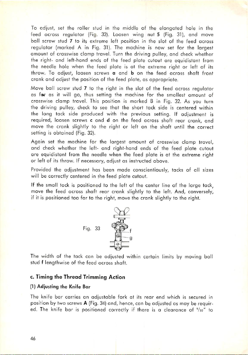
of
Fig. 33
The width of the tack can be odjusted within certain
stud f lengthwise of the feed across shaft.
c. Timing the Thread Trimming Action
(1)
Adjusting the Knife Bar
bar
The knife
carries an
position by two screws A
ed. The knife
46
bar
adjustable
(Fig.
forkatits
34)
and, hence, can be adjusted as may be requir
rear
is positioned correctly if there is a clearance of
limits
by moving ball
end
which is secured in
V32"
to
Page 48
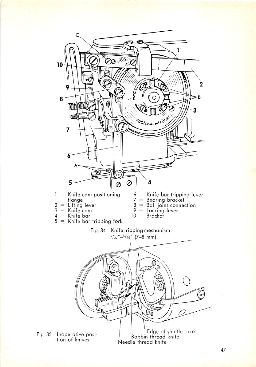
1 = Knife
cam
flonge
2 = Lifting lever
3 =
Knife
Knife
com
bar
bar
4 =
5 = Knife
Fig. 34 Knifetripping mechanism
positioning
tripping fork
V32"-Vu"
6 = Knife
7 =
Bearing
bar
tripping
bracket
8 = Ball joint connection
9 = Locking lever
10=Bracket
{7—8
mm)
lever
Fig. 35
Inoperative
tionofknives
posi
Needle
Bobbin
thread
Edge of shuttle
thread
knife
knife
race
47
Page 49
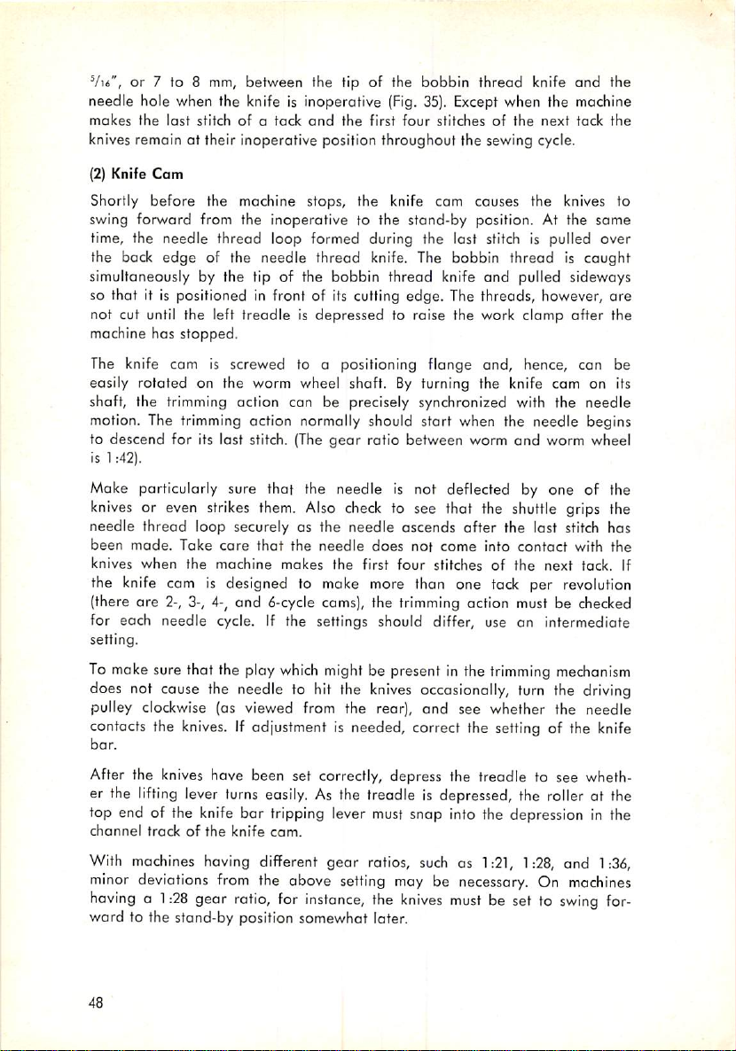
Vu", or 7 to 8 mm,
between
the tip of the
bobbin
thread
knife
and
the
needle hole when the knife is inoperative (Fig. 35). Except when the machine
makes
the
last
stitchofo
tack
and
the
first
four
stitchesofthe
next
tack
the
knives remain at their inoperative position throughout the sewing cycle.
(2)
Knife Cam
Shortly
before
the machine stops, the knife com causes the knives to
swing forward from the inoperative to the stand-by position. At the same
time, the needle thread loop formed during the lost stitch is pulled over
the back
simultaneously by the tip of the
so that it is positioned in front of its cutting edge. The threads, however,
edge
of the needle thread knife. The bobbin thread is caught
bobbin
thread
knife
and
pulled sideways
are
not cut until the left treadle is depressed to raise the work clamp after the
machine has
stopped.
The knife com is screwed to a positioning flange and, hence, can be
easily rotated on the worm wheel shaft.
By
turning the knife cam on its
shaft, the trimming action can be precisely synchronized with the needle
motion. The trimming action normally should stort when the needle begins
to descend for its last stitch. (The
is 1:42).
gear
ratio between worm
and
worm wheel
Make particularly sure that the needle is not deflected by one of the
knives
or even strikes them. Also
needle
thread
loop securely as the
been
made.
Take
care
knives
when
the
machine
that
the
makes
check
to see that the shuttle grips the
needle
ascends
needle
does
the
first four stitches of
not
come
after
the last stitch has
into
contact
the
with
the
next tack. If
the knife cam is designed to make more than one tack per revolution
(there ore 2-, 3-, 4-, and
6-cycle
cams), the
trimming
action must be
checked
for each needle cycle. If the settings should differ, use an intermediate
setting.
To make sure that the play
does not cause the needle to hit the
which
might be present in the
knives
trimming
mechanism
occasionally, turn the driving
pulley clockwise (as viewed from the rear), and see whether the needle
contacts the
bar.
knives.
If adjustment is needed, correct the setting of the knife
After the knives have been set correctly, depress the treadle to see wheth
er the
lifting
lever turns easily. As the treadle is depressed, the roller at the
top end of the knife bar tripping lever must snap into the depression in the
channel
With machines having different gear ratios,
minor
havinga1:28
ward to the stand-by position somewhat later.
48
trackofthe
deviations
gear
knife
from
ratio,
cam.
the above
for
instance,
setting
suchas1:21, 1:28,
maybenecessary.
the
knives
must
On
be set to
and 1:36,
machines
swing
for
Page 50

d. Adjusting the
Adjust
the work clamp frame on the feed plate carrier bar so that the
needle
will neither be deflected by, nor strike against, the work
feet, regardless
Work
Clomp
how
large the tack may be.
The
work
clomp
spring
clamp
pres
sure can be regulated by nut h (Fig. 30).
The clamp foot lifting lever (Fig. 2) must not contact the lifting studs pro
truding
will not press the material against the feed plate
has completed the last stitch and stopped, adjust the presser
from
the work clamp face plate as, otherwise, the work clamp feet
firmly.
After the machine
bar
and the
clomp foot lifting lever so that the top edge of the latter is positioned
just below the work clomp foot lifting studs.
e. Timing the Stop Motion
(1) Stop Motion Lever
Adjust both the tripping lever latch
so that the latch will leap about holfway into the upper notch of the catch
and
the stop motion lever catch
about
(Fig.36)
Hinge stud
Stop
motion lever
Stop
link
Stop
link rod
Stop
cam
Brake
lever
7 = Tripping lever
8 =
9 =
10 = Tripping
11 = Hand stop lever plate
12 =
Fig.36 Stop motion
Latch
Catch
Stop
dog
tripping
segment
49
Page 51

when the right treadle is depressed to start the machine. Also see that
gap
about
^U*",
there is a clearance
edge of the stop
link
and the lobe on the foce of the stop cam
or 2.0 mm, wide between the front
(Fig.
when the machine is in operation.
Brake lining
Brake
block
Set
screws
a
Brake
lever
Lock
nut
Driving pulley
(stop cam spring housing)
Regulating
Hinge
stud
screw
b
36)
(0 0)
K
(
i
•
Stop
Hinge
Stop
-
Brake
Brake
motion lever
stud
link
lever
block
OJ
Brake lining
Fig. 37 Adjusting the
brake
lever
Make particularly sure that the stop link snaps into the groove of the stop
cam freely. The tension springs must be strong enough to pull the stop
motion
and
brake lever assembly securely
against
the stop cam when the
machine stops. The stop link should be allowed only a small omount of
play in the stop cam groove. If the edges of the stop link or the stop cam
are worn, these ports must be replaced instantly.
(2)
Tripping Lever
Adjust the height of the tripping dog at the front end of the tripping lever
so that the stop tripping segment on the rim of the feed cam will depress
it far enough to ensure secure stopping of the machine.
50
Page 52

Stop
Wrong
Fig.38 Stop tripping segment set too for ahead
so that stop motion is tripped too early
Wrong
Fig.
39 Stop tripping segment set too for back so
that stop motion is tripped too late
tripping
segment.
Tripping
dog
Tripping lever
Right
Fig.
40Stop tripping segment set correctly
(3]
Broke Lever
The brake mechanism serves to slightly reduce the sewing speed shortly
before
the
machine
stops.
51
Page 53

Adjust so that the brake block is pressed
the
latter
has only half a revolution to go before the machine stops.
it has
stopped,
pulley by obout
a (Fig. 37)
appropriate.
1 = Lifting lever
2 = Knife
3 = Bearing
4 =
Bracket
5 = Boll joint connection
6 = Locking lever
7 =
Catch
8 = Lifting lever stop
check
whether
V44",
or 2.0 mm. To adjust, loosen brake block set screws
and
the lock nut on stop screw b
bar
tripping lever
bracket
Fig.41Adjusting the locking lever
the
brake
against
lever
the driving pulley when
can
be pulled
and
turn the
latter
away
from the
in or out, as
When
(4)
Stop Tripping Segments
Adjust the stop tripping segments on the rim of the feed cam so that the
tripping dog at the front end of the tripping lever will hit the rim of the
feed cam right behind the stop tripping segment when the machine is start
ed (Fig. 40).
(5)
Locking Lever
The
locking
work
clomp
lever serves to
from
being raised inadvertently before the
lock
the
lifting
lever in position and prevent the
stitching
cycle
completed. In addition, it prevents starting of the machine before the work
clamp
has been
and
move
(6) Belt Shifter
lowered
onto the goods.Toadjust,
the catchat its top end to the right or
loosen
screwd(Fig.
left,
as may be required.
41)
After you have loosened the set screws, adjust the belt shifter so that the
belt
runs
in the groove of the
belt
shifter)
when the
pulley when the machine is about to stop
52
machine
driving
pulley
(without
chafing
against the
is started, and is securely shifted to the idler
(Fig.
11).
is
Page 54
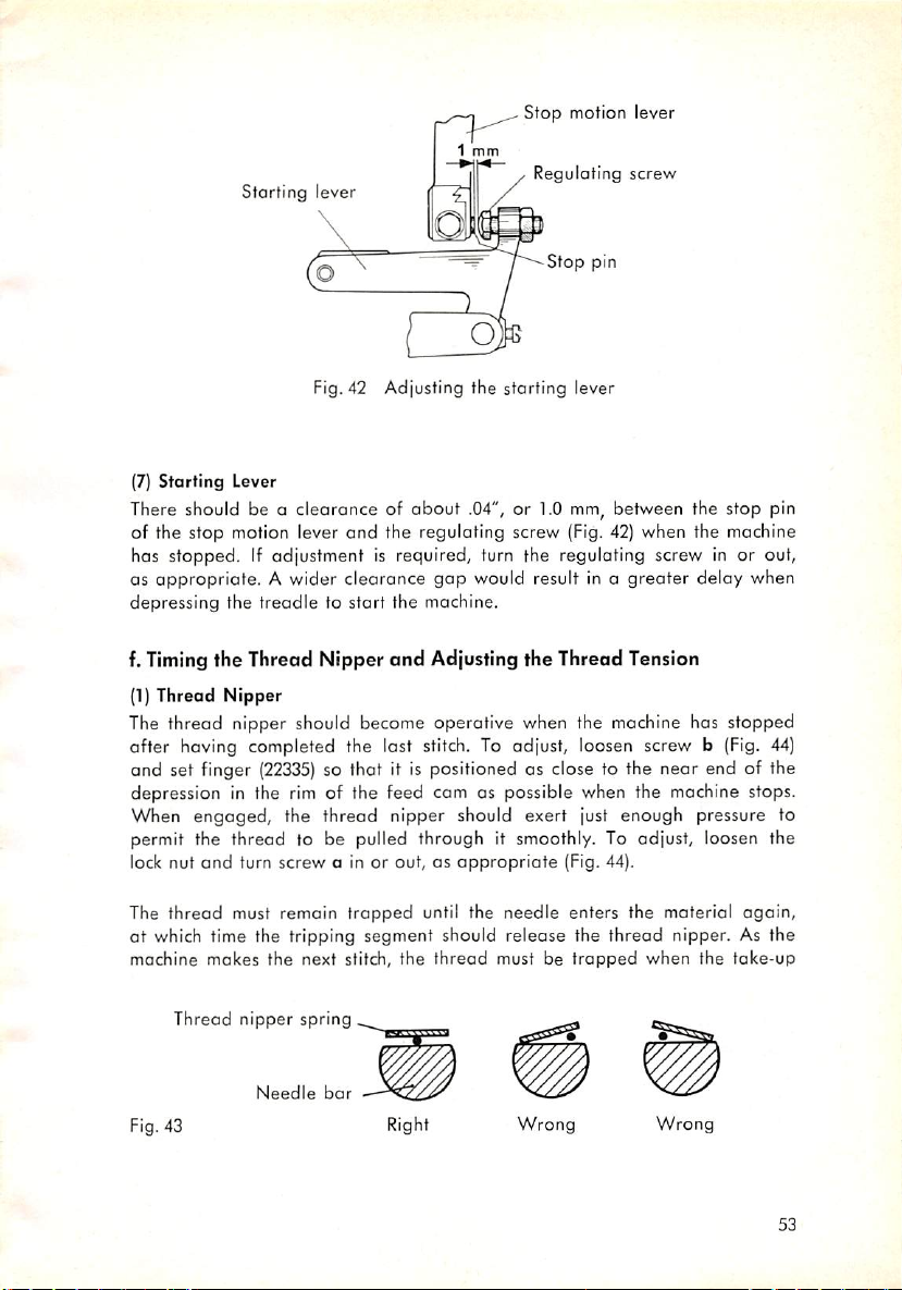
Starting
lever
Stop
motion lever
1
mm
Regulating
screw
—/^--Sfop
pin
Fig. 42 Adjusting the starting lever
(7)
Starting
There should be a clearance of about .04", or 1.0
of the stop motion lever
has
OS
appropriate. A wider clearance
Lever
and
stopped.Ifadjustment
mm,
between the stop pin
the reguloting screw
{Fig.
42) when the machine
is required, turn the regulating screw in or out,
gap
would result in a greater delay when
depressing the treadle to start the machine.
f.
Timing
(1) Thread
the Thread Nipper
Nipper
and
Adjusting the Thread Tension
The thread nipper should become operative when the machine has stopped
after having completed the last stitch. To adjust, loosen screw b (Fig. 44)
and set finger
(22335)
so that it is positioned as close to the near end of the
depression in the rim of the feed cam as possible when the machine stops.
When
engaged,
the thread nipper should exert just enough pressure to
permit the thread to be pulled through it smoothly. To adjust, loosen the
lock nut
and
turn
screw
a in or out, as
appropriate
(Fig. 44).
The
thread
must remoin
trapped
until the
needle
enters the material
again,
ot which time the tripping segment should release the thread nipper. As the
machine
makes
the
next stitch, the
thread
must be
trapped
when
the
take-up
Thread nipper spring
Needle
Fig. 43
bar
Right
Wrong
Wrong
53
Page 55

1 =
3 =
4 =
5 =
6 =
9 =
10
11 =
12
13
14
15
=
=
=
=
Thread nip
per tripping
lever
Thread nip
per
tripping
segment
Finger
Thread nip
per
closed
Thread nip
per
open
Thread nip
per
closed
Thread
per rod joint
Threod
Thread nip
stud
Thread nip
Thread nip
Thread nip
Thread
Thread nip
per
crank
per
hinge
per
rod
extension
per
lever
per rod
Needle
per
lever
per
spring
nip
nip
bar
nip
A
Fig.44 Thread nipper mechanism
Page 56

lever
has almost reached
the thread again after the needle has entered the goods.
To adjust, move the thread nipper tripping segment to or fro on the rim of
the feed cam, as appropriate. Thread nipper tripping
able in different
Spore Parts Catalogue). The order numbers
No.
22504
If severol thread nipper tripping segments should be arranged on the rim
of the feed cam, repeat this adjustment for each segment.
The above setting applies to normal operating conditions. If materials and
threads of different weights ore used on this machine, minor deviations from
this basic setting may become necessary.
Make sure the thread nipper lever does not jam and the thread nipper
spring releases the thread completely when the former is at its inoperative
position. The thread nipper spring should extend parallel to the flat spot
on the needle bar so that the thread
(Fig. 43).
The small prong of the thread nipper spring must project into the recess in
the needle bar so that the thread cannot slip out of the thread nipper
sewing.
lengthstosuit
its
No.
top
position.
machines
22504
j
tension
The
thread nipper
having
are
as follows:
No.
22454
will
should
release
segments
different gear ratios (see
]
not change
No.
while
are avail
22858
sewing
during
(2)
Needle
The Pfaff
The upper tension holds the needle thread taut while the threads are being
cut. Set this tension device so that it exerts just a light tension on the thread,
and the thread can be cut easily. If the tension is too light, the knives will
pull an excessive
will not be caught properly. If the tension is too tight, the thread will be cut too
early, leaving too short a
The
in the material. Begin by setting the
sion so that the stitchwill be pulled into the fabric properly.
Thread Tensions
3334
has two needle thread tensions
amount
lower, or main, tension holds the thread tout while the
of
thread
thread
end.
(Fig.53).
through the tension
upper
tension. Then set the main ten
and
stitch
the
thread
is being set
55
Page 57
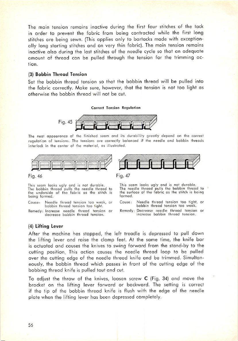
The main tension remains inactive during the first four stitches of the tack
in order to prevent the fabric from being contracted while the first long
stitches are being sewn.
ally long starting
stitches
{This
applies only to bartacks made with exception
and on very thin fabric). The main tension remains
inactive also during the last stitches of the needle cycle so that an adequate
amount of thread can be pulled through the tension for the trimming ac
tion.
(3)
Bobbin Thread Tension
Set the
bobbin
thread
tension so
that
the
bobbin
thread
will be pulled into
the fabric correctly. Moke sure, however, that the tension is not too light as
otherwise
The neot oppeorance of the finished seam and its durability greoHy depend on the correct
regulation of tensions. The tensions ore correctly balanced if the needle and bobbin threads
interlockinthe
This
The
the
being
Goose:
Remedy; Increase needle
seam
bobbin
underside
formed.
Needle
bobbin
decrease
the
centerofthe
looks
thread
of the
bobbin
Fig. 45
ugly
pulls the
thread
thread
bobbin
thread
material,osiliustroied.
and
is not
needle
fabric
as the stitch is
tension
too
tension
too
thread
thread
will
Correct
durable.
thread
weak,
tight.
tension or
tension.
notbecut.
Tension
This
The
to
the
formed.
Cause:
or
Remedy:
Regulation
seam
needle
surfaceofthe
looks
thread
Needle
bobbin
Decrease
increase
ugly
and
pulls the
fabricasthe
thread
tension
thread
tension
needle
bobbin
is not
bobbin
thread
thread
duroble,
thread
stitchisbeing
too
tight, or
too
weak.
tension
tension.
to
or
(4) Lifting Lever
After the machine hos stopped, the left treadle is depressed to pull down
the lifting lever and raise the clamp feet. At the same time, the knife bar
is actuated
cutting position.
over the cutting edge of the needle thread knife
eously, the bobbin thread which passes in front of the cutting
bobbing
and
causes the knives to swing forward from the stand-by to the
thread
knife is pulled tout
This
action causes the needle thread loop to be pulled
and
be trimmed. Simultan
and
cut.
edge
of the
To adjust the throw of the knives, loosen screw C (Fig. 34) and move the
bracket on the lifting lever forward or backward. The setting Is correct
if the tip of the bobbin thread knife is flush with the
edge
of the needle
plate when the lifting lever has been depressed completely.
56
Page 58
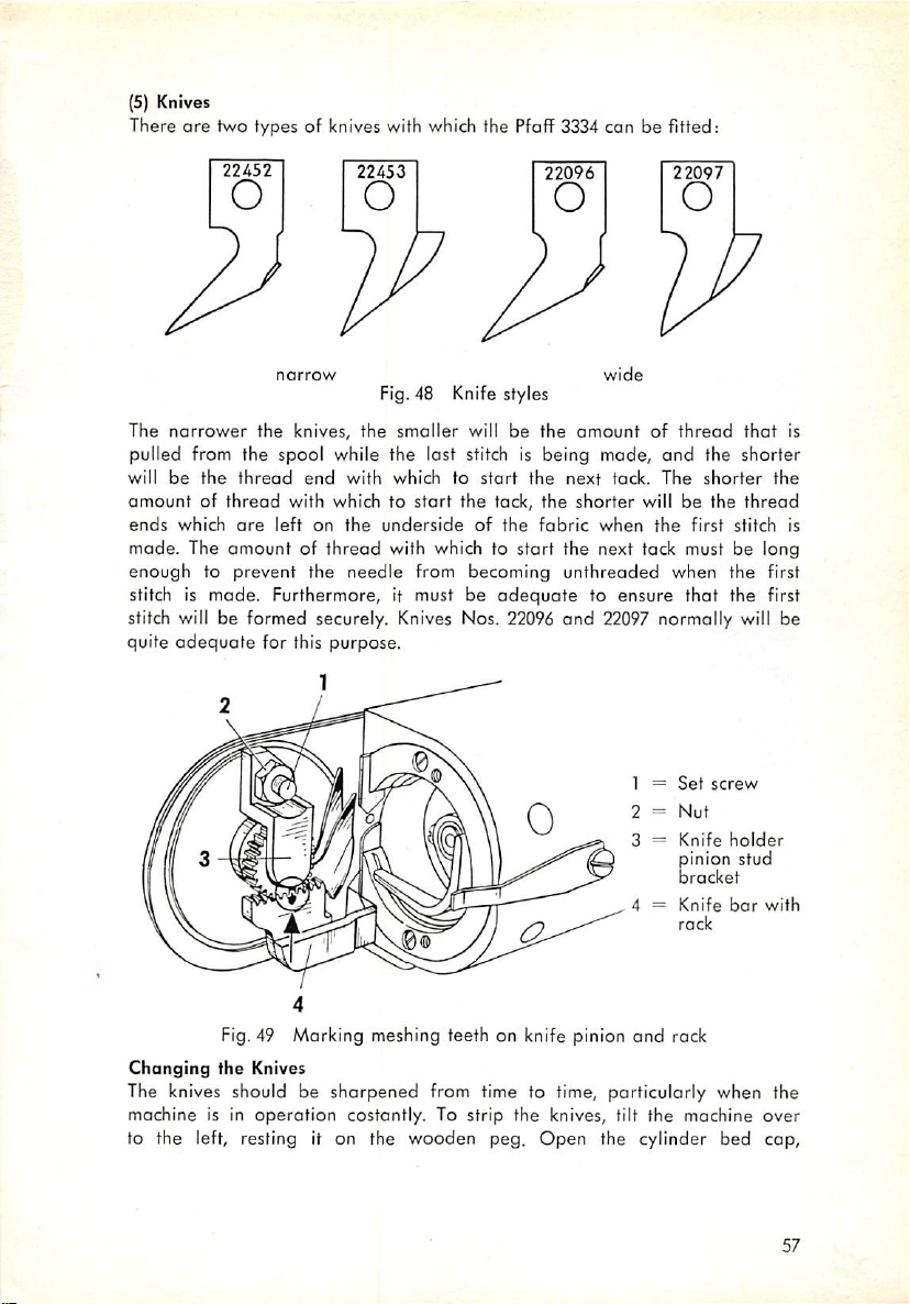
(5) Knives
There
are
two types of knives with which the Pfoff 3334 can be fitted:
22452
22453
22096 22097
wide
Fig. 48 Knife styles
The
narrower
pulled from the spool while the last stitch is
will
be
amountofthread
ends
which
made.
The
the
knives,
the
thread
end
with which to
are
left
amountofthread
the
smeller
with
whichtostart
on
the
underside
with which to
start
will be
the
of
tack,
the
the
amountofthread
being
made,
and
the
next
tack.
The
the
shorter
fabric
start
the next tack must be long
when
will be
the
the
shorter
the
first
that
shorter
the
thread
stitch
enough to prevent the needle from becoming unthreaded when the first
stitch is made. Furthermore, it must be
stitch will be formed securely. Knives Nos. 22096
quite
adequate
for this purpose.
adequate
to ensure that the first
and
22097 normally will be
1 =
Set
screw
2 =
Nut
=
Knife
holder
pinion stud
bracket
4 =
Knife
bar
rack
with
is
is
Fig,49 Marking meshing teeth on knife pinion
Changing
the Knives
The knives should be
machine is in
operation
sharpened
from time to time, particularly when the
costantly. To strip the knives, tilt the mochine
and
rack
over
to the left, resting it on the wooden peg. Open the cylinder bed cap.
57
Page 59

loosen the nut on the knife pinion stud brocket set screw (Fig. 49), and take
out this screw. Next, remove the knife pinion stud bracket and the knife
assembly.
There is a possibility of gettingatthe knives without removing the knife
holder pinion stud bracket. To do this, loosen the small
hexagon
screw b
(Fig. 50) on the feed plate, and pull the feed plate up out of its mount.
After removing the four
the trimming mechanism
are
The knives
out
this screw
by new ones.
secured to the knife
and
can
sharpen
needle
plate
set screws, both the
be pulled
the knives with a knife grinder, or
forward
carrier
out of the machine.
only by screw a (Fig. 50). Take
needle
replace
plate
and
them
Fig. 50
When you sharpen the knives, take
polished, but really sharpened, and that the tips
free from jags (Fig. 51).
In replacing the knives, make sure they fit in the knife
Changing
care
the
knives
that the cutting edge is not simply
are
well polished
carrier
and
groove
correctly. Then tighten screw a securely. The meshing teeth of both the rack
and
the pinion
justed
after
assembly in the machine, simply reverse the
are
spotted (Fig. 49) so that the knife
the knife assembly has
been
replaced.
above
bar
To
procedure.
need not be read
replace
the knife
To ensure that the trimming mechanism will function correctly, coordinate
the functions of both needle thread tensions properly. The upper needle
thread tension normally must be lighter, while the lower needle thread tension
should be tighter.
58
Page 60

Bobbin
Cutting
edge
thread
knife
Needle
thread
knife
Cutting
edge
Polished
Polished
Fig. 51 How to shorpen the knives
(6)
Adjusting the Stroke of the Thread Check Spring
The thread check spring performs the function of thread control, i.e. it
retains the excess
thread
which is
created
as the take-up lever descends
(but is not yet needed), and holds it back until the needle enters the goods.
The stroke of the thread check spring is checked by a stop and can be
adjusted by rotating this stop, as may be required. To do this, loosen the
set screw and turn the stop to the right or left, as appropriate.
The check spring is set correctly if it has completed taking up the balance
of
the
thread
when
the
needle
Needle
Size
70
80
90
stitches
Needle
Thread
Cotton
Silk
Weight
Nylon
Cotton
Silk
Nylon
Cotton
Silk
Nylon C
and
100/4
00
60/4
A & B
50/4
3 & C
A
0
into
Thread
Needle
the
Size
100
no
120
fabric.
Chart
Cotton
Silk
Linen
Nylon
Cotton
Silk
Linen
Nylon
Cotton
Silk
Linen
Nylon
Thread
Weight
40/4
C & D
80-90
D
36/3
D
60-80
D
30/3
D
60/3
F
59
Page 61

4. Stitching-Off
After the machine has been adjusted, stitch it off carefully, in
able
to stitch off the machine correctly, ask your customer to submit a suf
ficient amount of fhreod
work.
a. Sewing
Thread
and
fabric as well as a specimen of the finished
The Pfaff 3334 handles all customary branded threads of
linen, nylon, etc.,
Select the
b.
Needle
Insert the
faces
toward
proper
needle
you.
without
needle
into the
any
and
thread
opening
difficulty.
from the Table on
of the
needle
page
clampsothat
59.
order
silk^
its long
to be
cotton,
groove
The Pfaff 3334 normally uses the following needle systems:
System 34 R (or
System 332R (or
LR)
for Model B machines,
LR,
D, etc.) for
Model
and
C machines.
System 34 needles can be used only for needle sizes up to No. 110 be
cause
all needles of a
care
Take
shear
might
that
the needle does not
off the thread. If System 34 needles should prove
larger
size (No. 120
enter
the fabric up to the shank as this
and
up)
have
a thicker shank.
too
short,
use system 31x1 or 68x13 needles. Needles of this System fit the needle
also
in sizes 120
the needle bar. If your customer
System 34 R
machines
needles.
Earlier
bar
feature
machines
for System 134
and
needles
a needle
(manufactured
and
130,
and
require
wants
canbereplaced
bar
which is fitted to receive System 332
up to April, 1954)
134-35 needles.
onlyaslight
vertical
to use needles thicker
by System 287
needles.
were
fitted with a
adjustment
than
No. 110,
All
Model
needle
(29x1)
bar
of
C
60
Page 62

Fig. 52
c. Bobbin
Winding
Place the bobbin winder on the table so that its pulley will not contact the
machine belt when the winder is disengaged, and screw it down
The bobbin winder tension is
justed sideways to bring bobbin
two
screws
on
the
tension
Place a spool of
thread
arranged
and
bracket.
on spool pin 1
on the belt guard and can be ad
tension in line. To do this, loosen the
and
an empty bobbin on the
(Fig.
bobbin
52).
winder spindle. Lead the threod from the spool through thread guide 2
(from back to front), around and between tension discs 3,
and
down to
bobbin 4. Pull the thread through the slot in the bobbin, from the inside,
and
press in lever 5. Hold the
Having wound a few turns, break off the thread end
end
of the
thread
and
start
and
continue winding.
the machine.
The amount of thread to be wound on the bobbin is regulated by screw 6,
as
follows:
Turn screw right for more
or
left
for
less
thread,
thread.
61
Page 63

Fig. 53
d.
Needle
Pass the thread from the spool on the thread stand up
Threading
and
through thread
guide 1, through holes 2 and 3 of the spool pin, below thread guide 4, over
and from right to left around and between the tension discs of upper tension
5 and lower tension 6, as illustrated in Fig. 53. Pull the thread through the
thread check spring, below thread guide 8, through hole 9, to toke-up lever
10, from right to left through the hole of the take-up lever, down and through
thread guides11and
from front to back through the
62
12, between thread nipper spring and needle bar, and
needle
eye.
Page 64
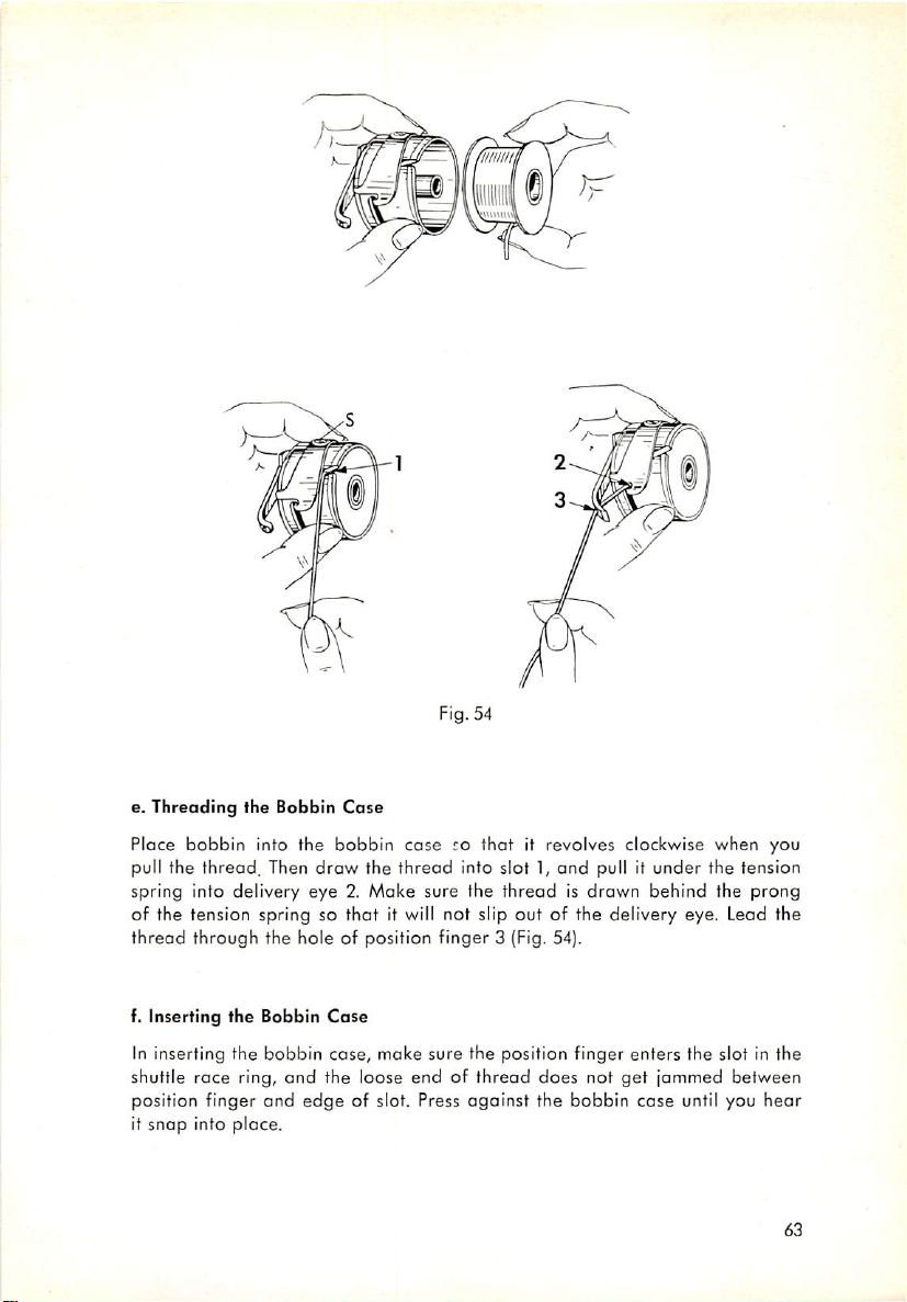
Fig. 54
I
null
e.
Threading
Place
pull the thread. Then
bobbin
the
into
Bobbin
the
draw
Cose
bobbin
the
caserothat
thread
into slot 1,
it revolves clockwise
and
pull it
under
when
you
the tension
spring into delivery eye 2. Moke sure the thread is drawn behind the prong
of the tension spring so
thread
through
f. Inserting
the hole of position finger 3 (Fig. 54).
the
Bobbin
that
it will not slip out of the delivery eye. Lead the
Cose
In inserting the bobbin case, make sure the position finger enters the slot in the
shuttle race ring, and the loose end of thread does not
position finger
it
snap
into
and
place.
edge
of slot. Press
against
the bobbin
get
jammed between
case
until you
hear
63
Page 65
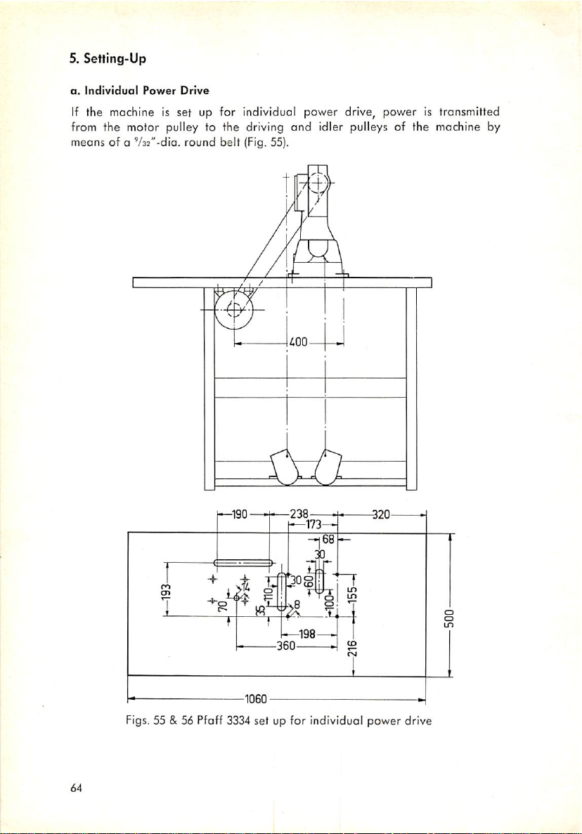
5.
Setting-Up
a.
Individual
Power
Drive
If the machine is set up for individual power drive, power is transmitted
from the motor pulley to the driving
meons of a V32"-dia. round belt (Fig. 55).
and
idler pulleys of the machine by
power
Figs. 55 & 56 Pfoff 3334 set up for individual
64
drive
Page 66
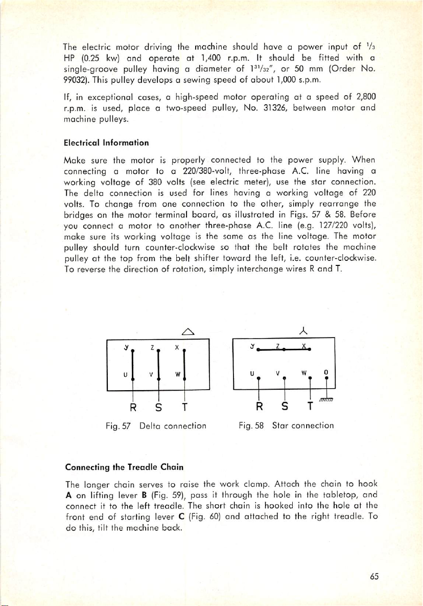
The electric motor driving the machine should hove a power input of
HP
(0.25
kw)
and
operate
single-groove pulley having o
99032).
This pulley develops a sewing speed of
at 1,400 r.p.m. It should be fitted with a
diameter
of I'Va:", or 50 mm (Order No.
about
1,000s.p.m.
If, in exceptional cases, a high-speed motor operating at a speed of 2,800
r.p.m. is used, place o two-speed pulley, No.
31326,
between motor and
machine pulleys.
Va
Electrical
information
Make sure the motor is properly connected to the power supply. When
connecting a motor to a 220/380-volt, three-phase A.C. line having a
working voltage of 380 volts (see electric meter), use the star connection.
The
delta
connection is used for lines having a working
volts. To change from one connection to the other, simply
voltage
rearrange
of 220
the
bridges on the motor terminal board, as illustrated in Figs. 57 & 58. Before
you connect a motor to another three-phase
A.C.
line (e.g.
127/220
volts),
make sure its working voltage is the same as the line voltage. The motor
pulley should turn counter-clockwise so that the belt rotates the machine
pulley at the top from the belt shifter toward the left, i.e. counter-clockwise.
To
reverse
the
directionofrotation,
2 X
y
V w
u
f
Fig. 57 Delta connection
simply
interchange
.Y, 2 ,
U V
I
1
R
Fig. 58
Star
wires R
A
X.
w
^
%
connection
and
0
1
/fTJhTf
T.
Connecting
the
Treadle
Chain
The longer chain serves to raise the work clamp. Attach the chain to hook
A on
lifting
leverB(Fig.
connectitto
front end of starting lever C
do
this, tilt
the
the
left
machine
59),
treodle.
back.
pass it
The
(Fig.
through
short
60)
and attached to the right treadle. To
the hole in the tabletop, and
chainishooked
into
the
holeotthe
65
Page 67

Q
Fig.59 Attaching the long chain
Fig. 60
66
Attaching
the
short
chain
Page 68

b.
Bench
Fig.61Pfaff 3334 set up on power benching
Power
Drive
Power is transmitted from o pulley on the line shaft
pulleys
two-speed
No.
31321
pulley
and No.
assembly
31323
and thence to the large-diameter
No.
31326.
Mount
the
diameter pulley of the two-speed pulley assembly.
To obtain the rated sewing speed of
1,000
s.p.m.,
the line shaft pulley from the following table:
Line
Shaft
Line
Shaft
RPM
300
350
400
Speed
Inches
15V4
13"/32
ZVs
Pulley Dia.
Millimeters
400
350
200
(Fig.
61)
to two
jockey
pulley
driving
belt on the
small-
select the correct size of
Pulley No.
30637
30627
30553
of
67
Page 69

Fig. 62 Individually
c. Individually Powered Machine on Power Benching
powered
machine on
power
benching
The Pfoff 3334 con be set up on existing power benching while being driven
by an individual motor. This arrangement (Fig. 62) is much more fovorable
than driving the machine from the line shaft. The special advantage of this
setup is that the
mochine
can be put out of operation, as may be required.
All that is required to drive a machine of this type is a short belt. Compared
with line shaft drive, this belt con be mounted more easily and will hardly
slip.
A tabletop provided with the necessary cutouts
and
boreholes can be obtain
ed from Pfoff at extra charge.
68
Page 70

6.
Subclass
Parts which differ with each subclass
Form No. 10080, Subclass
essentially the feed cam, the clomp feet,
assembly has to be
into
distributor.
a.
Changing
Unscrew wing nut 6 (Fig 63), loosen binding screw 9,
across
another,
regulator
Conversion
exchangedinorder
it is
advisable
the Feed Com
5. Unscrew nut 4,
are
compiled in the Annex. (See also
Organizations
of the Pfaff 3334).* Such
and
the feed plate. If the worm
to convert
to ship the machine to your
and
pull
the
feed
one
subclass machine
nearest
and
cam
off its
parts
are
gear
PfafF
strip feed
shaft.
placing the new feed com on its shaft, make sure the rollers ride in the
pattern-forming grooves without having any play. Tighten nut 4, and check to
see that the rollers do not chafe against the bottom of the grooves (see clear
ance
marked "x" in Fig. 63). Ifthe roller in the
the bottom of this groove, place a
spacer
rear
between
groove
should chafe
the hub of the cam
against
and
the
positioning flange on the worm wheel shaft. If the roller in the front groove
should chafe ogainst the bottom of this groove, place a spocer between the
feed across regulator
1 =
Feed
cam
2 =
Roller
3 =
Roller
stud
4 =
Nut
and
its bearing bracket.
L
5 = Feed across regulator
6 =
Wing
nut
7 = Ball screw stud,
upper
8 = Hinge stud
9 = Binding screw
10 = Ball joint connection
11 = Boll
12=Feed
13 = Feed
rear
stud,
across
across
lower
shaft
shaft
crank,
In
Available in Germon only
Fig.63 Exchanging the feed com
69
Page 71

Since minor deviations connot be entirely eliminated in machining the feed
cams, double-check the feed motion setting {see
poge
39).
The some applies to the adjustment of the thread nipper ond the
adjustment
procedure
on
stop tripping segments (see adjustment procedures on pages 53 and 52,
respectively),
b.
Changing
the Knife Com
Take out screws a on the lifting lever guide and remove the guide, Then take
out screw b in the knife
bar
tripping lever bracket, and swing the lifting
lever away. Loosen screw c and drive out toper pin d. Remove the knife com
with its positioning flange, and mount the new knife cam in reverse order
(Fig. 64).
1 = Lifting lever
2 = Knife
3 =
70
flange
Knife
cam
guide
positioning
4 = Knife
5 =
Knife
6 = Knife
cam
7 = Lifting lever
Fig. 64 Exchanging the knife cam
bar
tripping lever
bar
bar
tripping fork
Page 72
c. Changing the Work Clomp Feet
To
exchange
of their mount. Having attached the new feet, check to see that the needle
does
not
d.
Changing
The
feed plate can be
attaching
pins exactly. If necessary, rework the holes with a reamer. Also moke sure
that
the
against it as
bend the feed plate slightly.
All
other ports
book.
the
strike
them.Ifit
the Feed Plate
the
new
feed
plate
this
which
work
clomp
does,
stripped
feed plate,
bears
would
retard the
may
feet,
check
against
take out set
adjust
after
to see that
the
feeding
the
taking
needle
screws
positionofthe
out the
its
plate
motion.Ifadjustmentisrequired,
have to be exchanged are
and
pull
work
clamp.
hexagon
holes
fit over the
lightly,
but
does
listedinSection
the feet out
screw.
When
position
not
press
Dof this
7. Trouble Shooting
a. Skipped Stitches
(1)
Needle
(2)
Needle
(3)
Needle
(4)
Needle rise timed inaccurately, or needle set either
too high or too low.
(5)
Shuttle set too far away from needle.
b. Thread Breaking
(1) For
(2)
Needle point blunt or worn, or burrs and sharp edges
on
(3)
Thread caught between tension discs or under bobbin case
tension
(4)
Poor or knotty
(5)
Thread tensions too loose or too tight.
c. Needle Breaking
(1)
Needle
(2)
Needle too fine for the fabric, or deflected by hard spots
in the material
(3)
Stop cam spring broken, causing irregular stopping of machine.
(4)
Knives
(5)
Machine
(6)
Needle not centered correctly in clamp feet cutout.
bent.
incorrectly inserted.
too
fine
for
the
thread.
anyofthe
needle
timed improperly, causing needle to strike knives.
plate.
spring.
bent.
feeds
causes
enumerated
thread
used.
and
struck by the point of the shuttle.
while
needleisdowninmaterial.
above.
71
Page 73
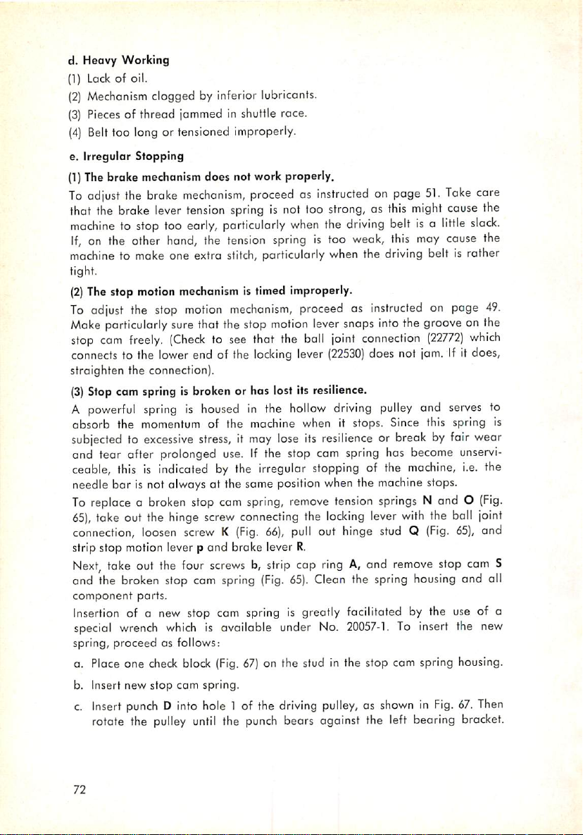
d. Heavy Working
(1)
Lack
of oil.
(2)
Mechanism
{3}
Pieces
{4}
Belt
e.
Irregular
(1)
Thebroke mechanism does not work properly.
To
adjust
the
that
machinetostop
If,
on the other
machinetomoke
tight.
(2)
Thestop motion mechanism is timed improperly.
To
adjust the stop
Moke
particularly sure that the stop
stop
cam
connects to the lower end of the
straighten the connection).
(3)
Stop com spring is broken or has lost its resilience.
A
powerful
absorb the momentum of the machine when it stops. Since this spring is
subjected to
and tear after prolonged use. If the stop cam spring has become
ceable, this is indicated by the irregular stopping of the machine, i.e. the
needle bar is not always at the same position when the machine stops.
To
replace a
65),
take out the hinge
connection,
strip stop motion lever p and brake lever
Next,
take
and the
component
Insertion of a new stop cam spring is greatly facilitated by the use of a
special
spring,
a. Place one
b. Insert new stop cam spring.
c.
Insert
rotate the
clogged by inferior lubricants.
of thread
too long ortensioned improperly.
Stopping
the
broke
brake
lever
too
[ommed
mechanism,
tension
eorly,
hand,
the
one extra
motion
in shuttle race.
proceedasinstructed
springisnot
particularly
tension
stitch,
springistoo
particularly
mechonism,
motion
freely.
(Check
to see that the
locking
springishousedinthe
excessive
broken
loosen
out
broken
parts.
wrench
proceed
check
punch
pulley
stress,itmay
stop cam spring,
screw
connecting
screwK(Fig.
the
four
screwsb,strip
stop cam
which
as follows:
spring
is available under No.
block
(Fig.
67)
D into hole 1 of the
until
the
punch
lose its
66),
(Fig.
on the stud in the stop cam spring housing.
driving
too
strong,asthis
when
the
driving
when
proceed as
lever
snaps intothe groove on the
ball
joint
lever
(22530)
hollow
driving
resilience
remove
pull
65).
tension
the
locking
out hinge stud Q
R.
cap
ringA,and
Clean the
20057-1.
on page
weak,
the
instructed
connection
does not jam. If it does,
pulley
or break by fair wear
springs
lever
spring
51.
Take
might
beltisa
this
driving
little
may
belt is rather
on poge
(22772)
and
N and O
with
the boll
(Fig.
remove
stop
housing
To insert the new
pulley,asshowninFig.
bears against the left bearing
cause
cause
serves
unservi
65),
and all
67.
bracket.
care
slack.
which
(Fig.
joint
and
cam
Then
the
the
49.
to
S
72
Page 74

Fig,
65 Stripping the stop motion and broke levers
d. Place check block U on the stud of the wrench, and push the wrench onto
the end of the orm shaft, as shown in
bears against the hub of the
the Novotex segment con be placed between both
While
holding
wrench
flat
Grease the stop cam spring lavishly before you replace the stop cam.
with
(long)
Having
the
stop
groove of the
stop motion
Moke
sure the brake
the driving pulley with sufficient pressure as the machine stops.
the segment in place
the
palm
of your left hand so that it
sides of the
check
replaced both the stop cam and the cap
cam
and see that it does not
driving
and
brake
pulley
levers.
lining
driving
blocks
and turn it
on the brake
Fig.
67, so that the hub of the wrench
pulley.
Now
depress
check
with
your right hand, press against the
will
not
the
blocks.
slip.
wrench
Moke
face toward the segment and the
ring,
check
the
resilience
jam.
(Insertasturdy
counter-clockwise).
block
engages the brakingsurfaceof
screwdriver
Then
mount
until
sure the
spring.
in the
the
of
73
Page 75

Fig. 66
Fig. 67 Inserting a new stop cam spring
74
Page 76

8.
Machine
a. Cleaning
Core
and
Oiling
Careful cleaning and regular oiling increase the service life of the machine
and
ensure smooth running.
When
the machine is delivered to the customer, all polished
parts
are
covered
with a rust-preventative grease. Remove this grease, together with the dust
which has
accumulated
in transit,
before
you put the machine in
operation.'
Also, squirt an ample amount of oil into all marked oiling points, unthread
the needle,
into all the bearings. All important oiling points
Figs. 68 through 70,
these oiling points
take
out the bobbin case,
and
by drops in Figs. 15 through 18. Wherever feasible,
are
marked
with red
and
run the machine to work the oil
are
marked by arrows in
paint
on the machine.
To get at the oiling points in the cylinder arm and the machine base, tip the
(Fig.
belt guard bock, loosen wing nut D
machine
over
to the left,
and
rest it on the
60), swing away catch E, tilt the
wooden
peg.
When the machine is in operation continuously, form the habit of removing
the lint which has
accumulated
in the vicinity of the shuttle,
and
putting a
drop of oil into the shuttle race. Repeat this procedure several times a day.
Run
the mochine with a scrap of material under the work clomp to absorb
all
excess
oil.
W
I
Fig. 68 Oiling points on the back side of the machine
75
Page 77

m
Fig. 69 Oiling points on the mochine arm
m
Fig. 70
Oiling
pointsonthe
76
top
cover
and
frontofthe
machine
Page 78

Certain sewing troubles, such as skipping of stitches or thread breaking, can
not be remedied by lavish oiling.
soil
the
workormix
with
the
dirt
Excessive
and
lintinthe
quantities of oil are liable to
machine
and
cause
hard
run
ning. Therefore, oil sparingly, but regularly!
Pfaff sewing machine oil is non-resinous ond has the right lubricating pro
perties for this machine. For this reoson, use no other oil in this machine,
b. Dismantling the Shuttle Race
If the machine is in operation continuously, clean the shuttle race from time to
time.
To dismantle the shuttle race, see that the machine is in the regular stopping
position.
cylinder
bobbin case and the bobbin. Take out screws h and I
Then
tilt it over to the
bed cap, press
down
left,
and
resting
pull
it out of the
it on the
wooden
machine.
{Fig.
peg. Open the
Remove
71), strip shuttle
the
race ring d, and take the shuttle out of the shuttle race. Take care that the
springs on screws h and i do not get lost.
The shuttle race proper need not be stripped for cleaning. Take a pair of
tweezers and remove pieces of thread that have accumulated in the
area
behind the shuttle race. Then, with a toothpick or similar wooden object,
clean
the shuttle race.
To assemble the shuttle
Never
use a metal tool for this purpose.
mechanism^
reverse the above procedure.
Fig.71Dismantling the shuttle race
77
Page 79

C.
Electromagnetic
1.
Genera)
a. Brief Description
InformaHon
Control
Lifting the work clomp or starting the machine previously required a con
siderable
working
the output, electromognetic control has now been introduced. On a
fitted with an X35 or X45 device, all the
is to tip on a push button (FS in Fig. 4), which is provided with two switch posi
tions. Actual work is then performed by solenoids HM
former
Since both solenoids
is either single or
in the circuit.
plied lo the rectifier which instantly raises the work clomp.
amountofenergy
cloy,
To reduce the physical strain and, at the same time, increase
on the port of the
operator
operator
has to do to start the machine
and
serves
lo raise
three-phase
When
and
lower
operate
A. C., a rectifier (GL in Fig. 72) has
motor
M is switched on,
the
work
clomp,
the
latter
starts
on D. C., but the current locally available
current
is simultoneously sup
in an
EM.
the
been
overage
PfafF
3334
While the
machine.
placed
Fig. 72
78
Page 80

b.
Key
to Symbols Used
Symbol
HS
GL
M
EM
HM
FS
ES
PL
SS
Si Fuse; 0,5 A;
LT
*) Please
state
voltage
Nomenclature
Master switch (triple-pole switch)
Rectifier
Electric motor;
permanent
duty; 1,400 r.p.m.
Starting magnet, TGB 9; 25% ED; 180 =
Clamp
lifting
magnet,
180V
=
Foot
control
switch
Switch
U 1 R
Spark
suppressor
Switch, Gusspilot
TGB 12;
D 6 U 1 P
GAl
100%
ED;
R
FNK3
Sewlight transformer, 220/12 V, type A VisVA
on your
orders
Order
97064
97080
98211
97260
97263
97162
97160
No.
')
98214
97104
98076
79
Page 81
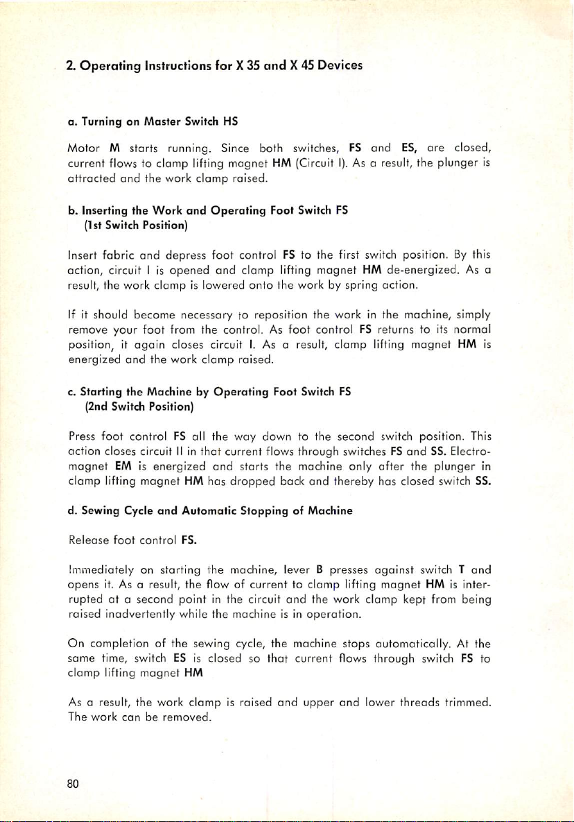
2.
Operating
Instructions for X35
and
X45 Devices
a. Turning on
Motor M starts running. Since both switches,
current flows to clamp lifting magnet HM (Circuit
attracted
b. Inserting the
(1st Switch Position]
Insert fabric
action, circuit I is
result, the work clamp is lowered
If it should
remove your
and
become
Master
Switch HS
FS
and
ES,
are closed,
I).
As a result, the plunger is
the work
Work
and
foot
clamp
raised.
and
Operating
Foot Switch FS
depress foot control FS to the first switch position. By this
opened
from the control. As
and clamp lifting magnet HM de-energized. As a
onto
the work by spring action.
necessary to reposition the work in the machine, simply
foot
control FS returns to its normal
position, it again closes circuitI.As a result, clomp lifting magnet HM is
energized
c. Starting the Machine by
Press
action closes circuit
magnet
and
the work
(2nd Switch Position)
foot
control FS all the
IIinthat
EM is
energized
clamp
raised.
Operating
current flows through switches FS
and
Foot Switch FS
way
down to the second switch position, This
starts the machine only
ofter
and
the
SS. Electro
plunger
clamp lifting magnet HM has dropped bock and thereby has closed switch SS.
d. Sewing Cycle
and
Automatic Stopping of Machine
in
Releose
Immediately on starting the machine, lever B presses
opens
rupted
raised inadvertently while the machine is in
foot
control
FS.
it. As a result, the flow of current to clomp lifting
at
a second
point
in the circuit
and
the work clamp kept from being
operation.
against
magnet
switch T
HM is inter
and
On completion of the sewing cycle, the machine stops automatically. At the
same
time, switch ES is closed so
clamp
lifting
magnet
As a result, the work
The
work
canberemoved.
80
HM
clamp
is raised
that
current flows through switch FS to
and
upper
and
lower
threads
trimmed.
Page 82
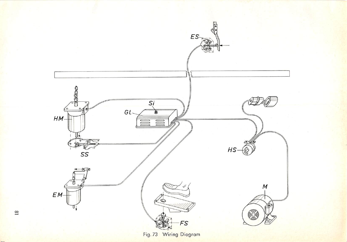
HM--
EM-
-
Fig. 73
Wiring
Diagram
Page 83

Fig,74As
82
the
machineisstarted,
opens
switchESand
magnet
HM.
leverBpresses
interrupts
SwitchESremains open throughout the sewing action.
the
against
flow
of current to
roller
Rand
clamp
thereby
lifting
Page 84
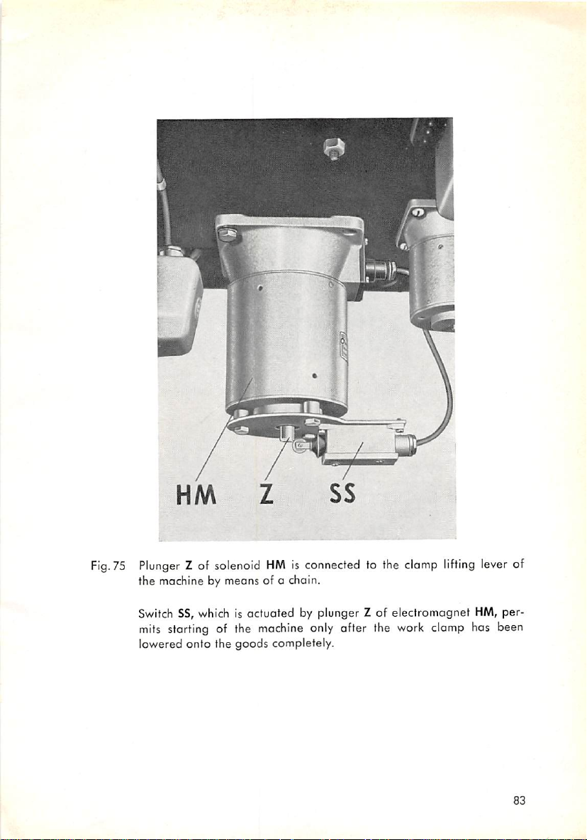
Fig.75Plunger
the machine by means of a chain.
Switch SS, which is actuated by plunger Z of electromagnet HM, per
mits
starting of the
lowered onto the goods completely.
Z of solenoid
HM
is connected to the
machine
only after the work clamp has been
clamp
lifting
lever of
83
Page 85

Fig.
76 PlungerZ, or starting magnetEMis connected to starting lever E by
means of link N. When solenoidEMisenergized, plunger Z pulls down
lever E and thereby storts the machine.
3. Working of Device
a.
Master
Switch
HS
Upon turning on master
storts running. At the some time A. C. flows through terminals 5
and 2 to the reectifier. As the rectifier starts operating, it closes aD.C. circuit
from
its positive pole through terminal 9, the coil of clomp lifting magnet
HM, terminals 12 and 14, switch FS, terminals 3
nals 7 and 8 to the negative pole. The work clamp is raised.
b.
Foot
Switch
FS
By
depressing foot controlFSto the first
under a) above is interrupted. Clamp
switch SS closed and the work clamp lowered.
c.
Solenoid
By
depressing foot control
EM
Simultaneously a circuit is closed from the negative pole of the rectifier
through
magnet
magnetisenergized
switch
FS,
EM,
terminals 9 and 10 to the positive pole. As a result, the starting
switch
terminal
and
starts
HS,
the motor is connected to the supply and
and
4, switch ES,
switch
position, the circuit discussed
lifting
FS
all the way down, the
13,
switch
SS,
terminal
the
machine.
magnet
HM
is de-energized,
machine
11,
the coil of starting
and6,and
and
termi
is started.
1
84
Page 86

R S T Mp
EM
t
HM
Fig. 77 Wiring
Diagram
Page 87

d.
Solenoid
HM
and
Switch
ES
Foot controlFSis released. To ensure that clamp lifting magnet HM will re
main inoperative while sewing, the circuit discussed under a} above is inter
rupted by switchESas long as the machine is in operation.
The two spark suppressors
FL,
which
are connected between terminals 8,
and 12, protect the contact points against excessive voltages. If, on special
request, the machine is equipped with sewlight transformer
suppressors
e.
Switch
are
connected to terminols 1
SS
and
2.
LT,
the spark
The function of switch SS is to interrupt the flow of current to machine
starting magnet
EM
for the short period of time it takes to lower the work
clamp onto the work. This prevents the machine from being started by quick
ly depressing foot control FS before the clomp has been lowered completely.
Switch SS closes the circuit to starting magnet
EM
only after the plunger in
clamp lifting magnet HM has dropped back (that is, when the clamp has been
lowered completely).
11
Fig. 78 10 mm =
86
15
mm="/as*
25
mm
=
'V32"
Fig. 79 12 mm = 'V32'
20
mm="/az''
Page 88

4. Mounting
a.
Switch
Attach
previously, drill screwholesinthe positions indicated in
ore
provided with
b.
Lever
On
previous
cent
machines
two
fillister
c.
Solenoid
and
ES
switchESto
B
machines,
are so designed that the
head
screws.
EM
Adjustment Procedures
bearing
bracketofstarting
lever.Onmachines
Fig.
appropriate
holes.
leverBshouldbemountedasshowninFig.
lever
con be
easily
supplied
78.
Recent
machines
screwedonwith
79.
Re
Connect starting magnetEMto link N on starting lever E by means of a bolt.
Press
starting lever E all the way down and adjust magnet
until
its plunger
is in a vertical linewith link N.Mork position of magnet on underside of table-
top
and
secure it in position with four
wood
screws.
Fig. 80
d.
Switch
SS
Switch
SS which is attached to clomp lifting magnet HM can be mounted
without any
difficulty.
Check
whether it is closed when the plunger has
dropped bock, and open when the plunger is attracted.
e.
Solenoid
Switch
without any
ped back,
HM
SS which is attached to clamp lifting magnet HM con be mounted
difficulty.
and
open when the plunger is attracted.
Check
whether it is closed when the plunger has drop
No special instructions are required for mounting the remaining parts of the
electromagnetic control mechanism. Merely take
convenient to
diagram).
operate
and
thot the wiring is clearly arranged. (See below
care
that the mechanism is
87
Page 89
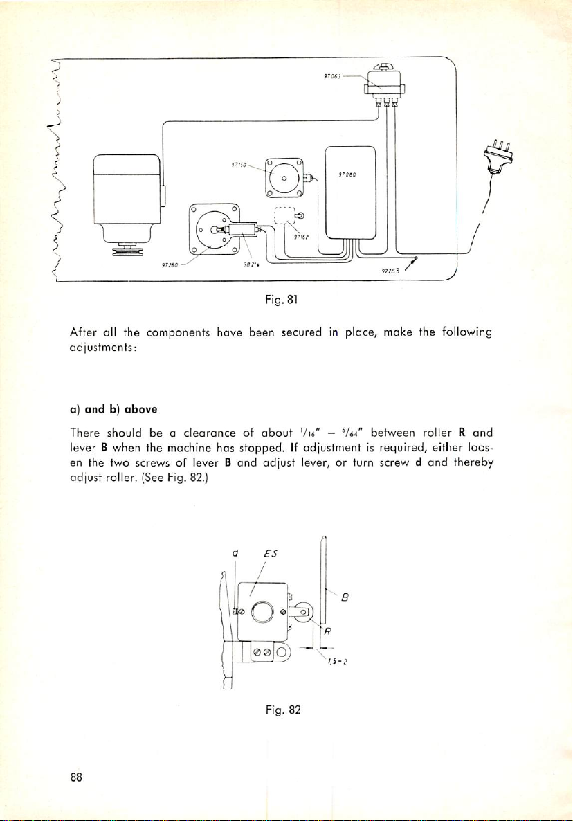
9's«a
Fig. 81
After all the components hove been secured in place, make the following
adjustments:
andb)above
a)
There
should
beaclearance
of
about
Vta" -
between
rollerRand
lever B when the machine has stopped. If adjustment is required, either loos
en the two screws of lever B and adjust lever, or turn screw d and thereby
adjust roller. (See Fig. 82.)
Fig. 82
Page 90
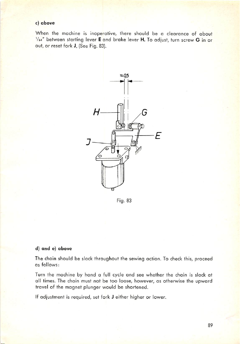
c)
above
When the machine Is inoperative, there should be a clearance of
764"
between starting lever Eand brake lever H. To adjust, turn screw G in or
out, or reset fork J. (See Fig. 83).
=sq5
about
d)
ande)above
The chain should be slack throughout the sewing action. To check this, proceed
as
follows:
Turn the machine by
hand
o full cycle
and
see
whether
the chain is slack
all times. The chain must not be too loose, however, as otherwise the upward
travel of the
magnet
plunger
would be shortened.
If adjustment is required, set fork J either higher or lower.
at
89
Page 91

Apart from the X35and X45electrical devices discussed above, the Pfaff
can be fitted with an X38 or X39 device (foot-operated and knee-operated
presser foot lifter, respectively).
Machines
equipped
with
the latter two devices
3334
ore set up in pairs in "V" tandem arrangement on a twin power toble.
90
Page 92
D.
Subclass
Information
The standard
range of tack designs differing both in shape
per tack. There is a special subclass
desired.
Pfoff
3334
has been adapted to produce a vastly diversified
and
in the number of stitches
machine
available for any tack design
The various subclass machines differ in the design of the feed cam, the
knife com, the clamp feet, and the feed plate. In oddition, each subclass
machine
usesa differentgear ratio inthe
worm
gear assembly.
All requests of our customers for the development of additional subclasses
capoble of performing special non-standard operations will be given our
careful
consideration.
Instructions for converting one subclass into another are given on page 69.
Listed in the following Tables
1. Subclasses having the same
2. Subclasses having the
same
are:
gear
knife cam
ratio
3. Subclasses requiring additional parts
(marked with an asterisk in Tables 1.
and
2.)
4. Principal parts varying from one subclass to another
5. Special
6. Tack designs
stitches
available
organizational
arranged
for
each
and
the
dimensionsofeach
ports
by shapes. This table offers a survey of the variations
basic
tcck
design,
tack.
and
indicates
the
total
number
of
Conversion of
machines
and
cam
is the
feed
Conversion
mochines
worm wheel have to be exchanged. (It is best to hove your
one
subclass machine into
have
the
same
gear
require no
additional
cam, work clomp feet,
of
one
subclass
have
different
gear
another
takes very little time if both
ratio. If both machines have the
conversion parts, all
and
feed plate.
machine
rotios
into
because
another
in this
that
has to be
takes
case
both the worm
more
same
knife
exchanged
timeifboth
nearest
Pfaff
representative perform this conversion job for you.).
If the machine is to be fitted to moke a different size bartock (within the
dimensions given in the tack design diagrams), a matching feed
work clomp feet
have
to be fobricated.
plate
and
and
91
Page 93

1. Subclasses Having the
c L I
Subclass
-9,-14*,-23*,-51,-71/2,-129,-158,-168,
-200, -205
Same
Gear
Ratio
Gear
RQfiQ
1:21
Worm
...
Worm
Thread
Nipper
Tripping
Segment
22143 22142 22
-5/2*,-130,-146,-160,-176,-177,-178*,-214 1:24 24016 24017 22505
21
-5/3*,-22, -24/1,-25, -27, -32, -41, 1:28
-75*,
-82*,
-103*,-112,
-166, -173, -180, -196, -210, -216, -232
-113,-
126, -128, -134, -141,
-91, -93, -94,
-95/2,-98,
268
21
269 22504
I
505
-28/5,-58, -68, -69, -73, -77, -81, 1:32
21
232
21
233 22 504
-101, -110, -127, -131,-153, -165, -172,
-181, -182, -185, -208, -213, -218, -234
-7, -8, -28/1,-62*, -71/1,-95/1,-196, 1:36 22212 22213 22454
-121*,-123, -138, -154, -155, -157, 167,
-174, -179, -199, -209/1,-209/2,209/3,-217,
-233
-1, -2, -3, -4,
-11, -12, -13*, -15, -16, -17, -18*,
19*, -20, -21, -26,
-29, -30*, -31, -33*, -34*, -35*, -36,
-38/1,-38/2,-39,
-37*,
.45,
-46*,
-49,
-55, -57,
-64, -65, -66, -67, -70, -72,
-76, -78, -79*, -80, -83, -85, -86,
-87, -88*, -89*, -90, -92, -97, -99,
-100*,-102,
-119, -124, -125, -132, -135, -136, -139,
-142, -147, -149, -150, -151, -152, -156,
-159, -162, -163, -164, -169, -175, -183,
-184, -186, -187, -191, -193, -201, -202,
-50, -52, -53, -54,
-59/1,-59/2,-59/3,-61,
-107,
-108,-114,
-203, -206, -207, -219, -220/1-10, -236
-188
-24/2,-48*, -56*, -84*, -96*,-104*,-111*, 1:56 22 574 22 575 22 858
-115*,-118*,-122,
-189, -190, -192, -194, -195, -198, -212,
-215, -231
-137, -140, -148, -161,
-5/r,-6,
-28/2*,28/3,-28/4,
-40, -42, -43,
-10*,
-63, 1:42 21 023 21 024 22 454
-74,
-116, -117,
1:48
24
842
24
843
—
-44*, -47*,
.143,
-211, -235
-60*,-105*,-109*,-120*,-133,
-144, -145, -170, -171, -197, -204,
Note: Machines which have a
1:48
and
are
nearest
92
to be converted to 1:56
Pfaff
agency.
* These
subclasses
1:72
gear
rotio of 1:21, 1:24, 1:28, 1:32, 1:36, 1:42 and
require
addiliorta!
22 694 22 695 —
and
1:72 must be shipped to the
parts
(see
Table
3).
Page 94

2. Subclasses Having
Gear
Ratio
One-Cycle
the
Same
Knife
Two-Cycle
Cam
Knife
Com
Three-Cycle
^
Cycle
Six-Cycle
1:21 -9, -14*, -23*, -129
1:24
1:28
1:32
1:36
-51, -71/2,-158,
-168, -200, -205
-5/2*,-130,
-176, -177, -178*,
-214
-5/3*, -22, -24,
-25, -27, -32,
-41, -82*, -91,
-93, -94, -95/2,
-98, -103, -113,
-126, -128, -134,
-141, -166, -173,
-180, -196, -216,
•232
-28/5, -68, -69, -58, -73, -127,
-77, -81, -101, -172
-110, -131, -153,
-165, -181, -182,
-185, -208, -213,
-218, -234
-8, -71/1, 95/1*, -62*, -167 -7
-106,
-138, -154, -155,
-157, -174, -179,
-160, -146
-121*,-123,
-75',-112,
-199 -28/1
-210
-209/1,-209/2,-209/3,
-217, -233
-2, -3, -15, -1, -4, -5/1*, -10*, -19*, -21
-16, -17, -20, -6, -11, -12, -28/2, -28/3,
1:42
1:48
-30*, -33*, -34*, -13*, -18*, -26, -29, -38/1,
-37*, -43, -46,
-55, -59/1,-59/2, -36, -39, -40, -45, -97,
-59/3, -66, -67, -49, -50, -52, -163, -186
-70, -72, -76, -53, -54, -57,
-79*, -83. -86, -61, -63, -64,
-87, -88*, -89*, -65, -74, -80,
-90, -92, -99, -85, -102, -108,
-100*,-107, -114, -119, -124, -135,
-116, -117, -125, -142, -147, -175,
-132, -136, -139, -184, -193, -219
-149, -150, -151,
-152, -156. -159,
-162, -164, -169,
-183, -107, -191,
-201, -902, -203,
-206, -207, -220/1-10,
-236
-188
-28/4,-31,
-35*,
-38/2,-42,
93
Page 95
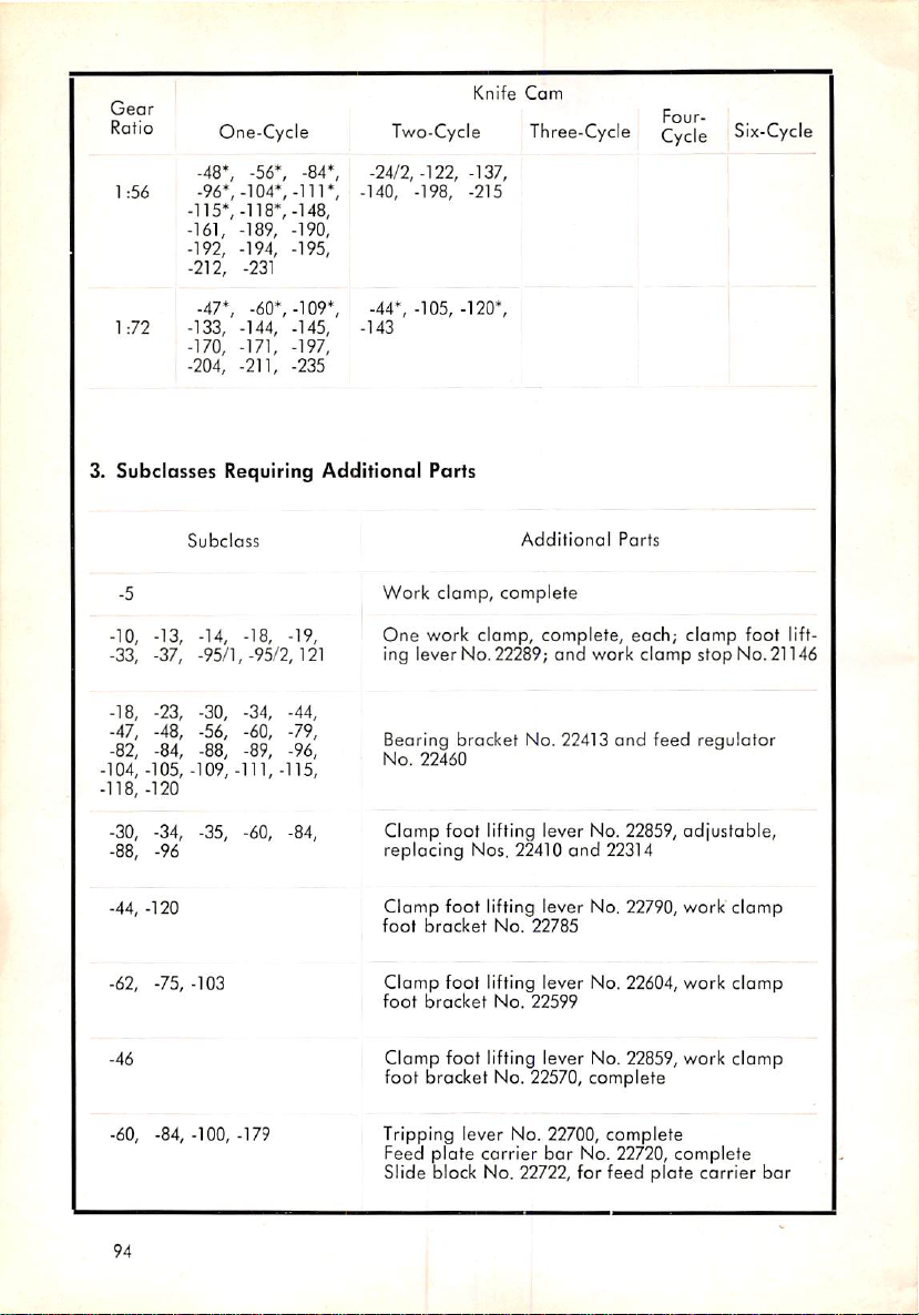
Geor
Rafio
One-Cycle
Knife
Two-Cycfe
Cam
Three-Cycle
Cycle
Six-Cycle
1:56
1:72
-48*, -56*, -84*,
-96*.-104*,-111",
-115*,-118*,-148,
-161, -189, -190,
-192, -194, -195,
-212, -231
-47*,
-60*,-109*,
-133,
-144, -145,
-170,
-171, -197,
-204, -211, -235
3. Subclasses Requiring
Subclass
-5
-10,
-13, -14, -18, -19,
-33, -37,
-18,
-47, -48, -56, -60, -79,
-82, -84, -88, -89, -96,
-104, -105, -109,
-118, -120
-95/1,-95/2,121
-23,
-30, -34, -44,
-111,-115,
-24/2,-122,
-140, -198,
-44*, -105, -120*,
-143
Additional
Work
One
Parts
clamp,
work
ing lever No. 22289;
Bearing bracket No. 22413
No.
22460
-137,
-215
clomp,
Addifional
complete
complete,
and
work
Parts
and
each;
clomp
feed
clamp
stop
regulator
foot
lift
No. 21146
-30, -34, -35, -60, -84,
-88, -96
-44,
-120
-62, -75, -103
-46
-60,
-84,-100,-179
94
Clomp foot lifting lever No. 22859,adjustable,
replacing
Clamp
foot
Clamp
foot
Nos, 22410
foot
lifting lever No. 22790, work clomp
bracket
bracket
No.
foot
lifting lever No. 22604,
No.
22785
22599
and
22314
work
clomp
Clamp foot lifting lever No. 22859, work clomp
foot bracket No. 22570, complete
Tripping lever No, 22700,
Feed plate carrier bar No.
Slide block No. 22722, for
complete
22720,
feed
plate
complete
carrier
bar
Page 96
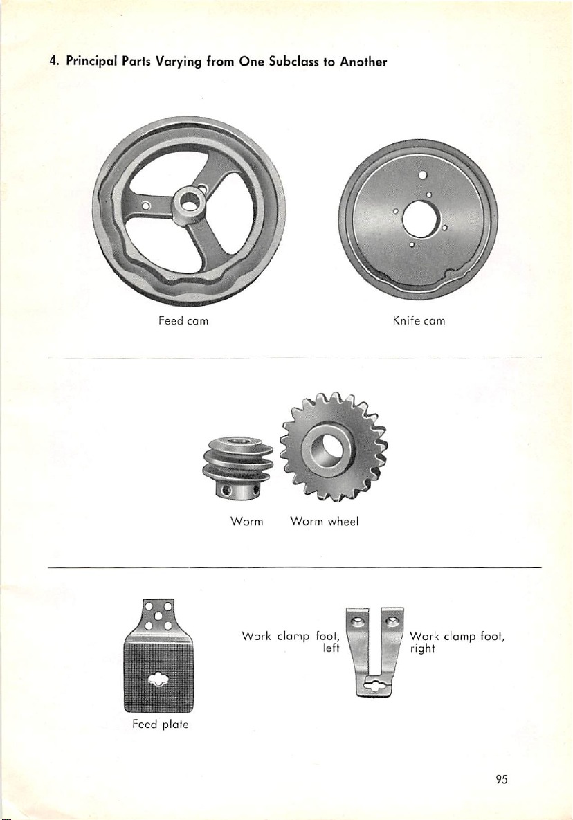
4. Principal Paris Varying from
Feed
cam
One
Subclass to Another
Knife
com
Feed
plate
Worm
Work
Worm
clamp
wheel
foot,
left
Work
right
clomp
foot,
95
Page 97

22146
5. Special
Organizational
Parts
21148
22289
22263
21
302
22264
Subclasses
437
22266
-10; -13; -14; -18; -19; -33; -38
700252
28200
22
685
Subclass
22
267
Subclass
701
-4
1
042
*
-5
21153
578
22197''14
324
22294
22193/94
701
22197x
046
14
22683
22 200
complete
22682
24006
96
22
68
Page 98

Subclass
Subclass
Subc
ass
-10
-14
-18
22220 complete
22229 complete
22221
22222 22224
22302
22300
22301
22342
22224
mmanmiiimTnii
Subclass
22370
481360
complete
-19
22369
complete
22340 complete
481 350
complete
97
Page 99
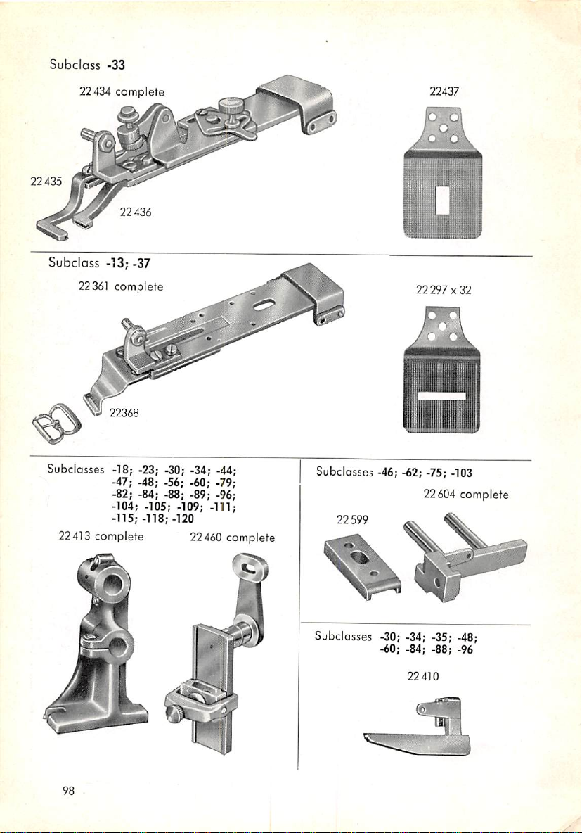
Subclass
-33
22434 complete
22435
22436
Subclass
22361
-"33;
-37
complete
Subclasses -18; -23; -30; -34; -44;
-47; -48; -56; -60; -79;
-82; -84; -88; -89; -96;
-104; -105; -109; -111;
22413
-115; -118;
complete
-120
22460
22437
22297x32
Subctosses -46; -62; -75; -103
22604 complete
22599
complete
Subclasses -30; -34; -35; -48;
•60; -84; -88; -96
22
410
98
Page 100
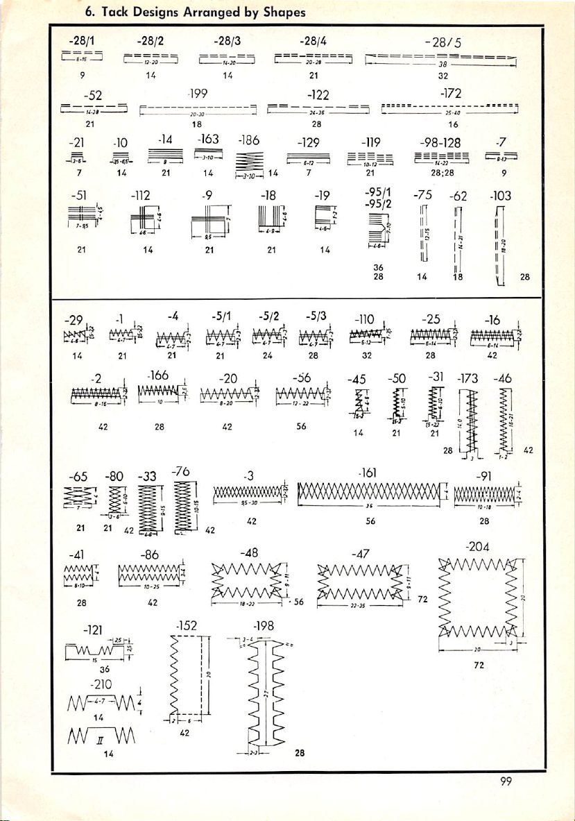
6. Tack Designs
ArrangedbyShapes
-28/1
-21
-137L
-51
I
,.,s
-28/2 -28/3 -28/4
^^
U
-52
-
21
-10
7
- t
14
-112
21
U
-14
I
—;;2
14
•199
-lO-X
—
18
-163
21
14
•9
86 -129
-18
M-lt
21
-122
13
I
28
C.
-119
•
f'O
•
7
-19
21
-it-t)-
21
-95/1
-95/2
14
36
28
-28/5
38
32
-172
—
»-«
16
_-98-128_
28:28
•75
-62
n
I
i
14
18
-7
-103
n
u
9
28
5/2 -5/3
-50
-31 -173
-46
-65 -80 -33
-41
WVNMI
_
^A/VWWWvVft
-121
-1«£L
36
-210
m^hN\
14
-86
72
,
99
 Loading...