

Page 1

3307-3/..
Industrial
®
3307-9/..
INSTRUCTION MANUAL
This instruction manual applies to machines from the
following serial numbers 2 752 431 and software
version 0366/001 onwards:
296-12-19 035/002
Betriebsanleitung engl. 06.09
Page 2

This Instruction Manual is valid for all models and subclasses listed in the
chapter "Specifications ".
The reprinting, copying or translation of PFAFF Instruction Manuals, whether in whole or
in part, is only permitted with our previous authorization and with written reference to the
source.
PFAFF Industriesysteme
und Maschinen AG
Hans-Geiger-Str. 12 - IG Nord
D-67661 Kaiserslautern
Page 3

Index
Contents ..................................................................................Page
1 Safety .................................................................................................................................... 7
1.01 Regulations ............................................................................................................................7
1.02 General notes on safety .........................................................................................................7
1.03 Safety symbols ......................................................................................................................8
1.04 Important notes for the user .................................................................................................. 8
1.05 Notes for operating and technical staff ..................................................................................9
1.05.01 Operating staff .......................................................................................................................9
1.05.02 Technical staff ........................................................................................................................9
1.06 Danger warnings .................................................................................................................. 10
2 Proper use .......................................................................................................................... 11
3 Specifi cations ..................................................................................................................... 12
3.01 General information ............................................................................................................ 12
3.02 Seam pattern sizes .............................................................................................................. 13
4 Disposal of Machine .......................................................................................................... 14
5 Transportation, packing and storage ................................................................................ 15
5.01 Transportation to customer‘s premises ............................................................................... 15
5.02 Transportation inside the customer‘s premises ................................................................... 15
5.03 Disposal of packing materials ..............................................................................................15
5.04 Storage ................................................................................................................................ 15
6 Explanation of symbols ..................................................................................................... 16
7 Controls .............................................................................................................................. 17
7.01 Main switch ......................................................................................................................... 17
7.02 Pedal .................................................................................................................................... 17
7.03 Balance wheel ..................................................................................................................... 18
7.04 Special operating elements of the PFAFF 3307-3/.. ............................................................. 18
7.04.01 Adjusting the button clamp .................................................................................................. 18
7.04.02 Lock lever of the blind stitching guide .................................................................................. 19
7.04.03 Setting the stem lengths ..................................................................................................... 19
7.04.04 Setting the penetration depth .............................................................................................. 20
7.04.05 Missed stitch detection key .................................................................................................20
7.05 Special operating elements of the PFAFF 3307-9/01 ........................................................... 21
7.05.01 Setting the stem length ....................................................................................................... 21
7.06 Control panel ........................................................................................................................21
7.06.01 Screen displays ....................................................................................................................22
7.06.02 Display symbols ...................................................................................................................22
7.06.03 Function keys .......................................................................................................................22
8 Mounting and commissioning the machine .................................................................... 25
8.01 Installation ............................................................................................................................25
Page 4

Index
Contents ..................................................................................Page
8.01.01 Adjusting the table height .................................................................................................... 25
8.01.02 Drilling template for the table-top ........................................................................................ 26
8.01.03 Connecting the plug-in connections and earth cable ........................................................... 27
8.01.04 Fitting the reel stand ............................................................................................................ 28
8.02 Commissioning .................................................................................................................... 28
8.03 Switching the machine on / off ............................................................................................ 28
8.04 Setting the seam pattern size ..............................................................................................29
8.04.01 Establishing the value for parameter "204" .......................................................................... 29
8.04.02 Altering parameter "204" ......................................................................................................30
9 Setting up ...........................................................................................................................31
9.01 Inserting the needle ............................................................................................................. 31
9.02 Threading the sewing thread ............................................................................................... 32
9.03 Special setting-up work on the PFAFF 3307-3/.. ..................................................................33
9.03.01 Selecting the button type and program number ................................................................. 33
9.03.02 Adjusting the button clamp to the button size .....................................................................34
9.03.03 Selecting the stem length ................................................................................................34
9.03.04 Setting the stem length for the short stem .........................................................................35
9.03.05 Setting the stem length for the long stem ........................................................................... 35
9.03.06 Selecting/setting the "sew-through button attachment" function .........................................36
9.03.07 Selecting/setting the "blind sewing" function .......................................................................36
9.03.08 Selecting/setting the "blind sewing through the facing" function ......................................... 37
9.03.09 Allocating the stem length to the seam version .................................................................. 38
9.03.10 Loading plate for loading stay button ...................................................................................38
9.04 Special setting-up work on the PFAFF 3307-9/.. ..................................................................39
9.04.01 Setting the stem length ....................................................................................................... 39
9.05 Inserting and removing the SD-memory card ...................................................................... 39
9.06 Activating the sequence mode ............................................................................................ 40
10 Sewing ................................................................................................................................ 42
10.01 Sewing with the PFAFF 3307-3/.. .. .....................................................................................43
10.02 Sewing with the PFAFF 3307-9/.. .. .....................................................................................45
10.03 Error messages ....................................................................................................................46
11 Input .................................................................................................................................... 47
11 .01 Seam pattern input on machines from subclass -3/.. .. .......................................................47
11 .01.01 Seam pattern input for two-hole and self-shank buttons ..................................................... 47
11 .01.02 Seam pattern input for three-hole buttons ........................................................................... 48
11 .01.03 Seam pattern input for four-hole buttons .............................................................................49
11 .01.04 Seam pattern input for six-hole buttons ............................................................................... 50
11 .02 Seam pattern input on sub-class -9/.. machines ..................................................................53
11 .03 Sequence input ....................................................................................................................54
11 .04 Program Management .......................................................................................................55
11 .04.01 Calling up the program management ..................................................................................56
11 .04.02 Displaying programs in the machine memory ..................................................................... 57
Page 5

Index
Contents ..................................................................................Page
11 .04.03 Displaying programs on the SD-memory card ..................................................................... 58
11 .04.04 Copying programs to the SD-memory card ......................................................................... 59
11 .04.05 Copying programs to the machine memory ....................................................................... 60
11 .04.06 Deleting programs in the machine memory ........................................................................ 61
11 .04.07 Deleting programs on the SD-memory card ........................................................................ 62
11 .04.08 Formatting the SD-memory card ......................................................................................... 63
12 Care and maintenance ....................................................................................................... 64
12.01 Maintenance intervals ..........................................................................................................64
12.02 Cleaning the machine .......................................................................................................... 64
12.03 Cleaning the hook compartment .........................................................................................65
12.04 Cleaning the air fi lter/lubricator ............................................................................................65
12.05 Checking/adjusting the air pressure ..................................................................................... 66
12.06 Top up the oil for needle drive ..............................................................................................66
12.07 Topping up oil for the gears ..................................................................................................67
12.08 Lubricating the gear shaft .................................................................................................... 67
13 Adjustment ......................................................................................................................... 68
13.01 Notes on adjustment ........................................................................................................... 68
13.02 Tools, gauges and other accessories ..................................................................................68
13.03 Abbreviations ....................................................................................................................... 68
13.04 Toothed belts of the main drive ...........................................................................................69
13.05 Top needle bar position (reference position) ........................................................................ 70
13.06 Pre-adjusting the needle height ........................................................................................... 71
13.07 Position of the needle to the needle hole ............................................................................ 72
13.08 Basic position „button clamp raised“ ..................................................................................73
13.09 Sensor board of the needle drive (in dismantled condition) ................................................. 74
13.10 Basic setting of the needle drive .......................................................................................... 76
13.11 Position of the hook shaft to the needle ..............................................................................77
13.12 Adjusting the drag link mechanism ......................................................................................78
13.13 Needle rise and hook clearance ........................................................................................... 79
13.14 Readjusting the needle height ............................................................................................. 81
13.15 Adjusting the loop spreader ................................................................................................. 82
13.16 Position of the loop spreader to the needle ......................................................................... 83
13.17 Adjusting the thread trimmer on the PFAFF 3307-3/.. .........................................................84
13.18 Manual cutting test (only on the PFAFF 3307-3/..) ............................................................... 85
13.19 Adjusting the thread catcher (only on the PFAFF 3307-3/..) ................................................. 86
13.20 Adjusting the thread loop support on the PFAFF 3307-3/.. ..................................................87
13.21 Adjusting the spreader (only on the PFAFF 3307-9/..) .......................................................... 88
13.22 Adjusting the thread loop support on the PFAFF 3307-9/.. ..................................................89
13.23 Aligning the button holder (only on the PFAFF 3307-9/..) .....................................................90
13.24 Basic position of the button holder (only on the PFAFF 3307-9/..) ....................................... 91
13.25 Adjusting the thread trimmer on the PFAFF 3307-9/.. .........................................................92
13.26 Basic position of the button clamp drive on the PFAFF 3307-3/.. ........................................93
13.27 Basic position of the button clamp drive on the PFAFF 3307-9/.. ........................................94
Page 6

Index
Contents ..................................................................................Page
13.28 Aligning the button clamp (only on the PFAFF 3307-3/01) ................................................... 95
13.29 Adjusting the clamp pressure (only on the PFAFF 3307-3/..) ...............................................96
13.30 Basic setting of the end knotting equipment .......................................................................97
13.31 Adjusting the retaining fi nger of the end knotting equipment .............................................98
13.32 Adjusting the lifting lever of the end knotting equipment .................................................... 99
13.33 Adjusting the reed switch ..................................................................................................100
13.34 Setting the angle for the end knotting ...............................................................................101
13.35 Adjusting the moment tension .......................................................................................... 102
13.36 Adjusting the thread puller ................................................................................................. 103
13.37 Adjusting the thread clamp ................................................................................................ 104
13.38 Adjusting the thread regulator ........................................................................................... 105
13.39 Adjusting the thread wiper ................................................................................................ 106
13.40 Adjusting the thread air jet ................................................................................................. 107
13.41 Aligning the holder of the blind stitching guide (only on the PFAFF 3307-3/01) ................. 108
13.42 Basic position of the blind stitching guide (only on the PFAFF 3307-3/01) ......................... 109
13.43 Adjusting the height of the mounting plate (only on the PFAFF 3307-3/01) ........................110
13.44 Basic position of the stay button plate (only on the PFAFF 3307-3/01) ...............................111
13.45 Adjusting the insert plate (only on the PFAFF 3307-3/01) ...................................................112
13.46 Adjusting the reed switch for the insert plate (only on the PFAFF 3307-3/01) ....................113
13.47 Insert plate pressure (only on the PFAFF 3307-3/01) ..........................................................114
13.48 Adjusting the stem fi nger (only on the PFAFF 3307-3/01) ...................................................115
13.49 Detaching/fi tting the blind stitching unit (only on the PFAFF 3307-3/01)
13.50 Parameter settings ..............................................................................................................118
13.50.01 Selecting the function group and altering the parameter ...................................................118
13.50.02 Entering / altering the access code .....................................................................................119
13.41.03 Allocating access rights ..................................................................................................... 120
13.50.04 Parameter list ..................................................................................................................... 121
13.51 Description of the error messages .................................................................................... 128
13.52 Sewing motor errors .......................................................................................................... 130
13.44 Internet update of the machine software .......................................................................... 131
13.44.01 Update with null modem cable .......................................................................................... 131
13.44.02 Update with SD-card .......................................................................................................... 132
14 Wearing parts ...................................................................................................................134
15 Pneumatics-switch diagram ........................................................................................... 135
16 Circuit diagrams ............................................................................................................... 138
Page 7

Safety
1 Safety
1
.01 Directives
The machine has been constructed in accordance with the requirements listed in the
EC Declaration of Conformity and the Declaration of Incorporation.
In addition to this Instruction Manual, also observe all generally accepted, statutory and
other regulations and legal requirements and all valid environmental protection regulations!
The regionally valid regulations of the social insurance society for occupational accidents or
other supervisory organizations are to be strictly adhered to!
1.02 General notes on safety
● This machine may only be operated by adequately trained operators and only after having
completely read and understood the Instruction Manual!
● All Notes on Safety and Instruction Manuals of the motor manufacturer are to be read be-
fore operating the machine!
● The danger and safety instructions on the machine itself are to be followed!
● This machine may only be used for the purpose for which it is intended and may not be
operated without its safety devices. All safety regulations relevant to its operation are to
be adhered to.
● When exchanging sewing tools (e.g. needle, roller presser, needle plate and bobbin),
when threading the machine, when leaving the machine unattended and during maintenance work, the machine is to be separated from the power supply by switching off the
On/Off switch or by removing the plug from the mains!
● Everyday maintenance work is only to be carried out by appropriately trained personnel!
● Repairs and special maintenance work may only be carried out by qualifi ed service staff
or appropriately trained personnel!
● Work on electrical equipment may only be carried out by appropriately trained personnel!
● Work is not permitted on parts and equipment which are connected to the power supply!
The only exceptions to this rule are found in the regulations EN 50110.
● Modifi cations and alterations to the machine may only be carried out under observance
of all the relevant safety regulations!
● Only spare parts which have been approved by us are to be used for repairs! We express-
ly point out that any replacement parts or accessories which are not supplied by us have
not been tested and approved by us. The installation and/or use of any such products can
lead to negative changes in the structural characteristics of the machine. We are not liable
for any damage which may be caused by non-original parts.
7
Page 8
Safety
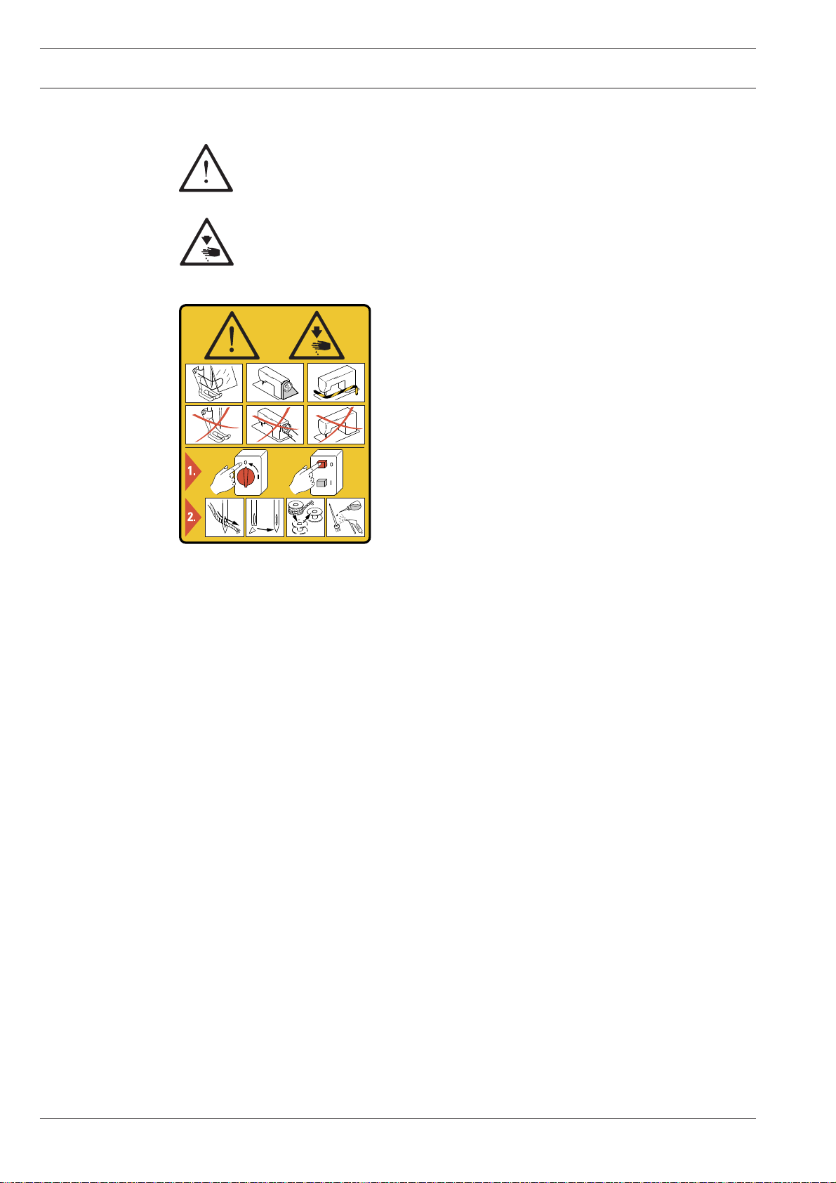
1.03 Safety symbols
Danger!
Special points to observe.
Danger of injury to operating or technical staff!
Caution
Do not operate without fi nger guard and safety devices.
Before threading, changing bobbin and needle, cleaning
etc. switch off main switch.
I
1.04 Important notes for the user
This instruction manual belongs to the equipment of the machine and must be available
●
to the operating staff at all times.
●
This instruction manual must be read before the machine is operated for the fi rst time.
●
Both operating and technical staff must be instructed on the safety devices of the machine and on safe working methods.
●
It is the duty of the user to operate the machine in perfect running order only.
The user must ensure that none of the safety devices are removed nor put out of work-
●
ing order.
The user must ensure that only authorized persons operate and work on the machine.
●
For further information please refer to your PFAFF agency..
8
Page 9

Safety
1.05 Notes for operating and technical staff
1
.05.01 Operating staff
Operating staff are the persons responsible for setting up, operating and cleaning the machine and for eliminating any malfunctioning in the sewing area.
The operating staff is obliged to observe the following points:
The notes on safety in this instruction manual must always be observed!
●
Any working methods, which adversely affect the safety of the machine, must be avoi-
●
ded.!
Loose-fi tting clothing should be avoided. No jewellery, such as chains and rings, should
●
be worn!
●
Ensure that only authorised persons enter the danger area of the machine!
●
Any changes occurring on the machine, which may affect its safety, must be reported to
the user immediately.
1.05.02 Technical staff
Technical staff are persons who have been trained in electrical engineering/electronics and
mechanical engineering. They are responsible for lubricating, servicing, repairing and adjusting the machine.
The technical staff is obliged to observe the following points:
The notes on safety in this instruction manual must always be observed!
●
Before carrying out any adjustment or repair work the main switch must be switched off
●
and measures taken to prevent it from being switched on again!
●
Never work on parts or equipment still connected to the power supply! Exceptions are
only permissible in accordance with the regulations EN 50110.
●
All safety covers must be replaced after the completion of maintenance or repair work!
9
Page 10
Safety
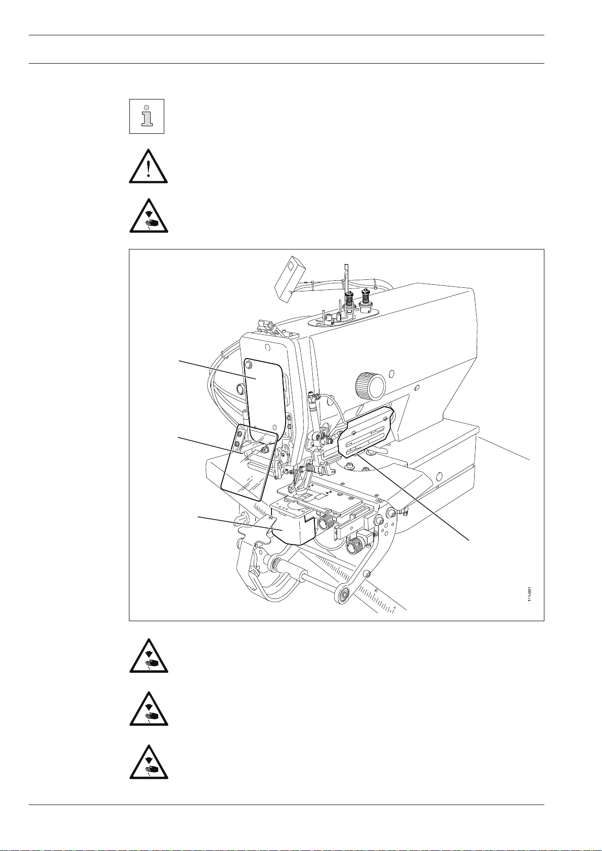
1.06 Danger warnings
Fig. 1-01 shows the PFAFF 3307-3/01, which has the same safety appliances
as the PFAFF 3307-9/02.
A working area of 1 m must be kept free both in front of and behind the
mach-ine, so that easy access is possible at all times.
Never put your hands in the sewing area during sewing!
Danger of injury by the needle!
Fig. 1 - 01
1
3
2
4
Only operate the machine with covers 1 and 2 closed!
10
Danger of injury from the movement of the take-up lever and the hook!
Do not operate the machine without eye shield 3!
Danger of injury from fl ying needle or button fragments!
Do not operate the machine without protective cover 4 (only on the
PFAFF 3307-3/01)! Danger of injury from clamp drive!
Page 11

2 Proper use
The PFAFF 3307-3/01 is used for the automatic attachment of buttons in the clothing
industry.
The PFAFF 3307-9/01 is used to wrap button stems in the clothing industry.
Proper use
Any use of these machines which is not approved by the manufacturer shall be
considered as improper use! The manufacturer shall not be liable for any damage arising out of improper use! Proper use shall also be considered to include
compliance with the operation, adjustment, service and repair measures specifi ed by the manufacturer!
11
Page 12

Specifi cations
3 Specifi cations
▲
3.01 General information
Max. sewing speed:
PFAFF 3307-3/01 ...................................................................................................... 2000 min
PFAFF 3307-9/02 ...................................................................................................... 1600 min
Stitch type: ........................................................................................................................... 107
Needle bar stroke: ..........................................................................................................46 mm
Max. thickness of workpiece: ...........................................................................................4 mm
Max. work clamp clearance: ...........................................................................................17 mm
Fabric clearance (crosswise to sewing arm): ................................................................235 mm
Fabric clearance (lengthwise to sewing arm): .................................................................30 mm
Max. size of sewing area: ........................................................................................8 x 12 mm
Number of stitches: ..................................................................................freely programmable
Feed type: ............................................................................................................... intermittent
Power supply: ...................................................................................... 230 V ±10%, 50 / 60 Hz
Power consumption: ............................................................................................. max. 1,3 kVA
Fuse protection: ................................................................................................... 1 x 16 A, inert
-1
-1
◆
Working air pressure: ......................................................................................................... 6 bar
Air consumption: ...........................................................................................~1,2 l / work cycle
Noise data:
Noise emission level at workplace with a sewing speed of 1800 spm
Sewing cycle 2.5 sec. on and 2.5 sec. Off: ..................................................... LpA = 68,5 dB(A)■
(Noise measurement in accordance with DIN 45 635-48-A-1, ISO 11204, ISO 3744, ISO
4871)
Sewing head dimensions:
Length: ............................................................................................................. approx. 514 mm
Width: .............................................................................................................. approx. 200 mm
Height: .............................................................................................................approx. 450 mm
Weight of sewing head: ........................................................................................approx. 65 kg
Needle system:
PFAFF 3307-3/01 .................................................................................................................. 190
PFAFF 3307-9/02 ................................................................................................. 332 LG HK SP
Needle size for fi ne materials: ...................................................................................... 70 - 100
Needle size for medium-weight materials: ................................................................. 100 - 120
12
▲
Subject to alterations
◆
Depending on cut-out size of bed plate
■
KpA = 2,5 dB
Page 13
Specifi cations
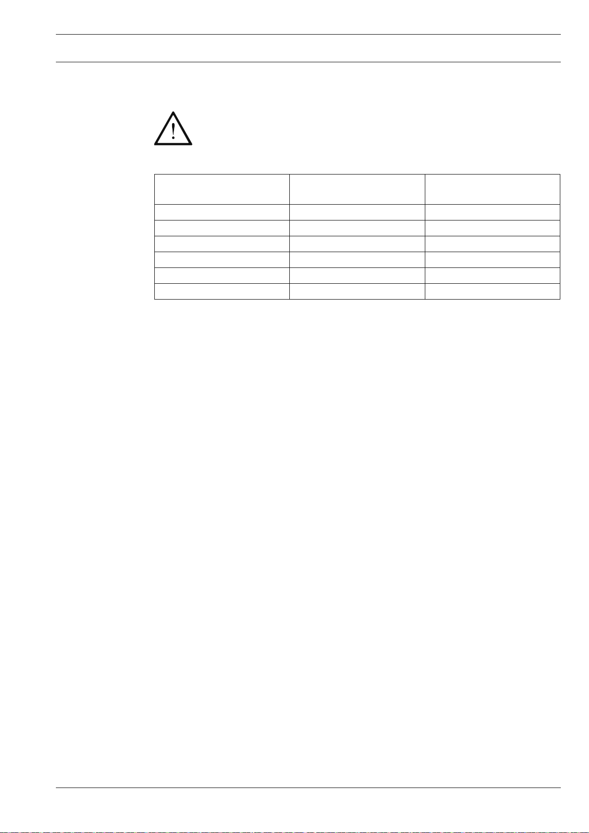
3.02 Seam pattern sizes
When changing part sets parameter "204" must be adapted to the cut-out
size of the bed plate, see Chapter 8.04 Setting the seam pattern size.
If this instruction is not observed there is a risk of severe damage to the
machine!
Value for
parameter "204"
1 7 mm x 7 mm 5 mm x 5 mm
2 8 mm x 8 mm 6 mm x 6 mm
3 9 mm x 9 mm 7 mm x 7 mm
4 10 mm x 10 mm 8 mm x 8 mm
5 11 mm x 11 mm 8 mm x 9 mm
6 10 mm x 14 mm 8 mm x 12 mm
Cut-out size of the
bed plate
Size of seam pattern
13
Page 14

Disposal of Machine
4 Disposal of Machine
Proper disposal of the machine is the responsibility of the customer.
●
The materials used for the machine are steel, aluminium, brass and various plastic
●
materials. The electrical equipment comprises plastic materials and copper.
●
The machine is to be disposed of according to the locally valid pollution control regula-tions; if necessary, a specialist ist to be commissioned.
Care must be taken that parts soiled with lubricants are disposed of separately
according to the locally valid pollution control regulations!
14
Page 15

Transportation, packing and storage
5 Transportation, packing and storage
5
.01 Transportation to customer‘s premises
The machines are delivered completely packed.
5.02 Transportation inside the customer‘s premises
The manufacturer cannot be made liable for transportation inside the customer‘s premises
nor to other operating locations. It must be ensured that the machines are only transported
in an upright position.
5.03 Disposal of packing materials
The packing materials of this machine comprise paper, cardboard and VCE fi bre. Proper disposal of the packing material is the responsibility of the customer.
5.04 Storage
If the machine is not in use, it can be stored as it is for a period of up to six months, but It
should be protected against dust and moisture.
If the machine is stored for longer periods, the individual parts, especially the surfaces of
moving parts, must be protected against corrosion, e.g. by a fi lm of oil.
15
Page 16

Explanation of symbols
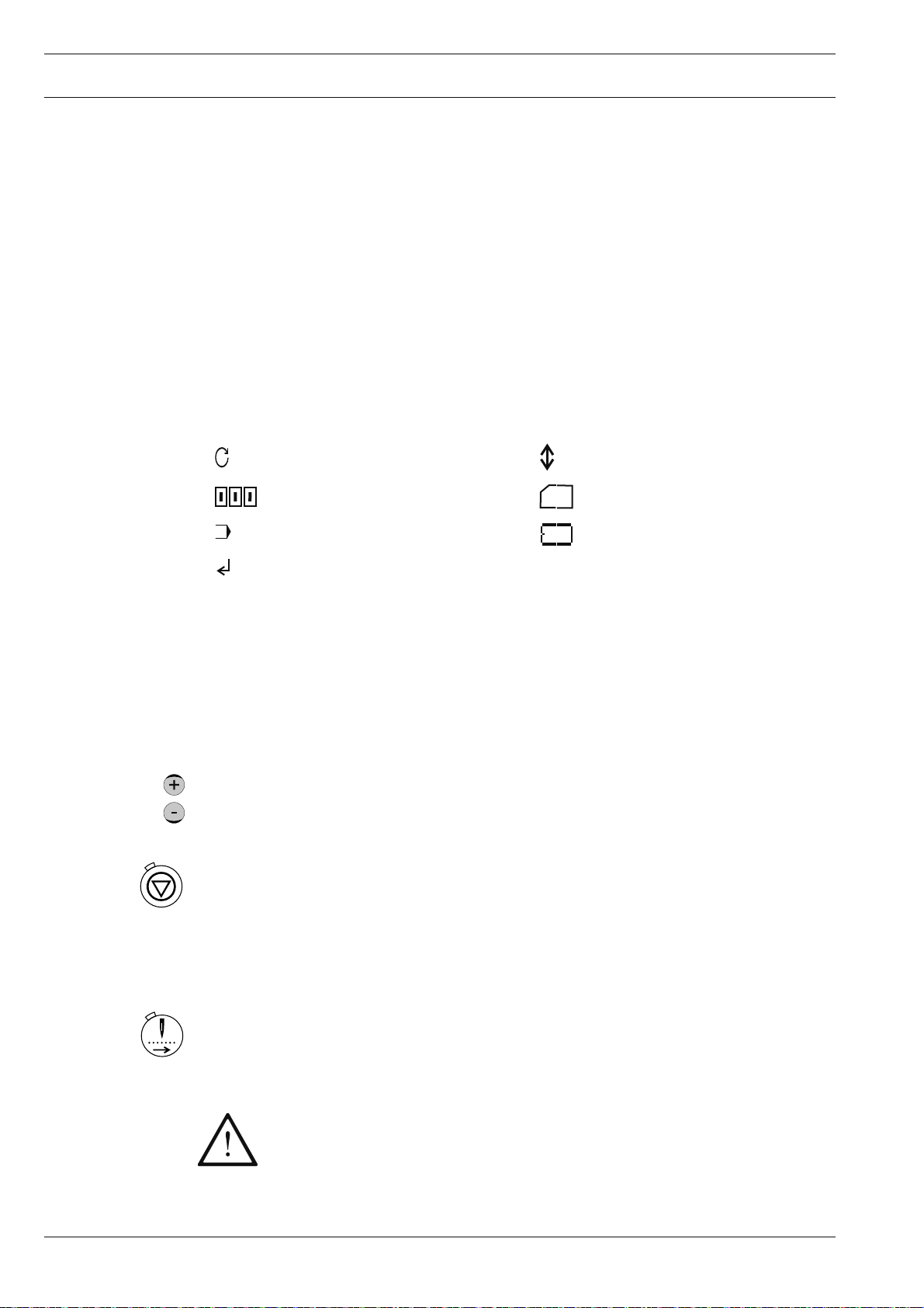
6 Explanation of symbols
In this instruction manual, work to be carried out or important information is accentuated by
symbols. These symbols have the following meanings:
Note, information
Cleaning, care
Lubrication
Maintenance, repairs, adjustment, service work
(only to be carried out by technical staff)
16
Page 17
Controls
56-067
7 Controls
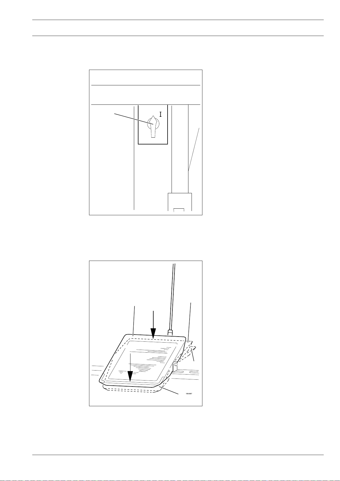
7
.01 Main switch
The machine is switched on or off by tur-
●
ning the main switch 1.
Fig. 7 - 01
7.02 Pedal
1
0
-1 = change stem height
(only on sub-class -3/01)
Fig. 7 - 02
0 = Neutral position
0
+1
+1 = Lower button clamp
+2 = Sewing
+2
-1
17
Page 18
Controls
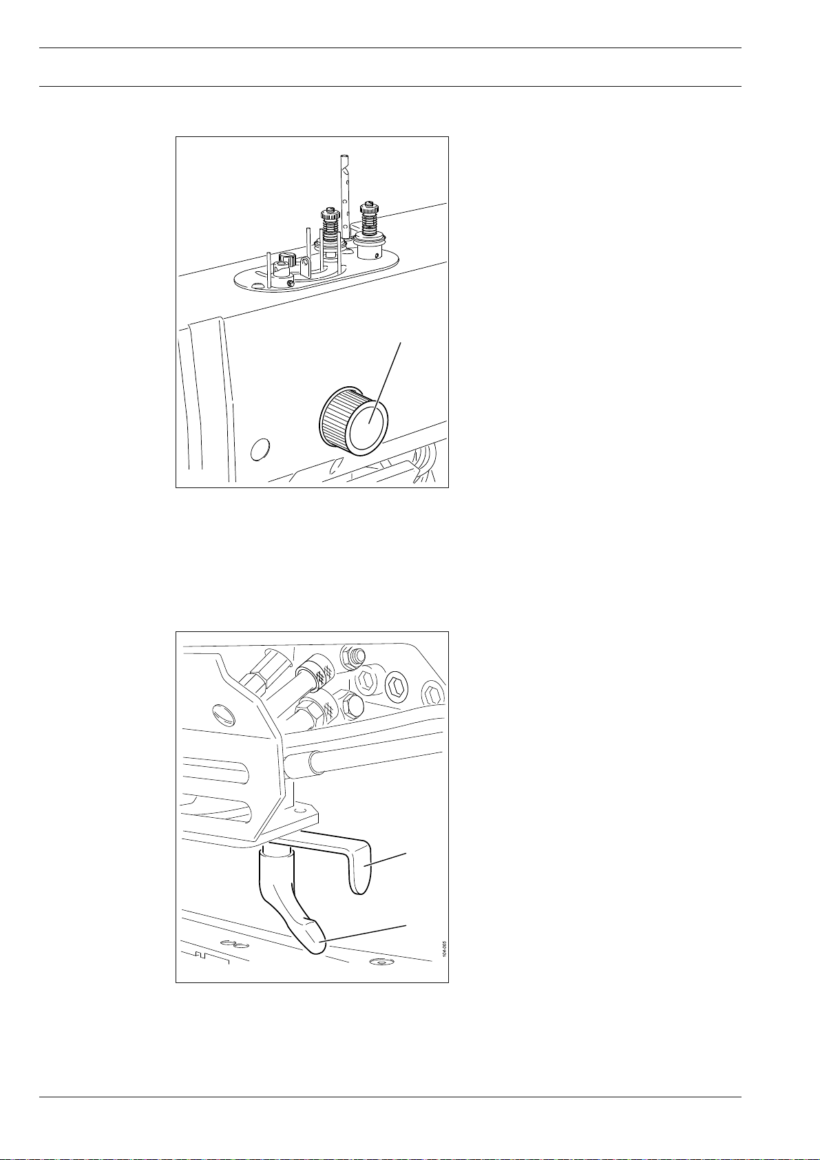
7.03 Balance wheel
By pressing and holding down balance
●
wheel 1, it is possible to adjust the needle bar manually.
1
111-002
Fig. 7 - 03
7.04 Special operating elements of the PFAFF 3307-3/..
7
.04.01 Adjusting the button clamp
After loosening T-screw 1, with sliding
●
bar 2 the button clamp is adjusted to
match the button size, see Chapter
9.03.02 Adjusting the button clamp to
the button size..
2
18
1
Fig. 7 - 04
Page 19
Controls
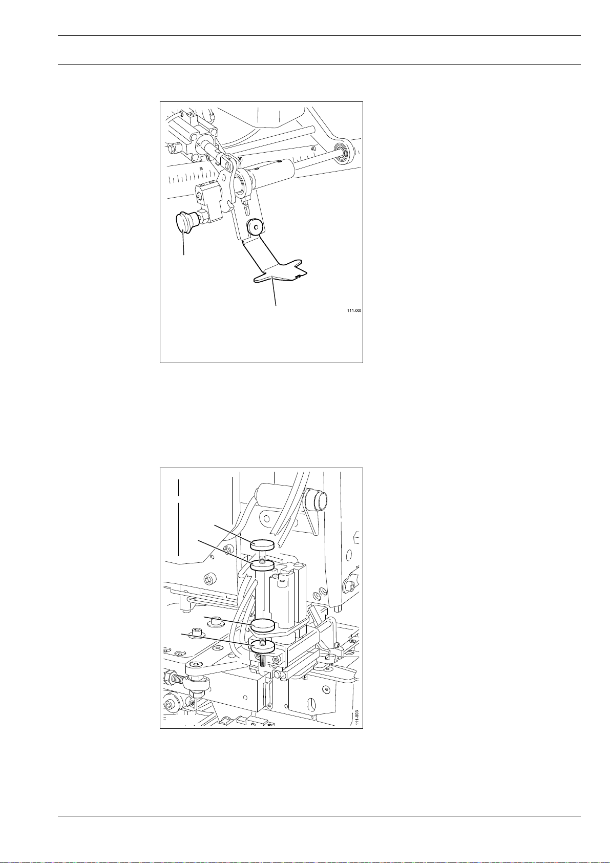
7.04.02 Lock lever of the blind stitching guide
Lock lever 1 is used to retract the blind
●
stitching guide 2 when sewing without it.
Blind stitching guide 2 is retracted and locked.
1
2
Fig. 7 - 05
7.04.03 Setting the stem lengths
2
1
4
3
fter loosening locknut 1, the stem
●
height for the long stem is set by turning
screw 2.
After loosening locknut 3, the stem
●
height for the short stem is set by turning screw 4.
Fig. 7 - 06
19
Page 20
Controls
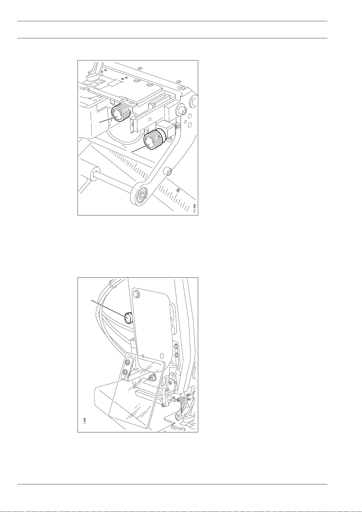
7.04.04 Setting the penetration depth
To set the penetration depth (visible
●
seam), turn adjustment wheel 1.
To set the penetration depth for blind stit-
●
ching, turn adjustment wheel 2.
1
2
Fig. 7 - 07
7.04.05 Missed stitch detection key
1
●
Key 1 lights up, when an error is detec-
ted in the sewing process.
Acknowledge the error signal by pressing
●
key 1.
By pressing key 1 in addition the thread
●
can be tightened as required
20
Fig. 7 - 08
Page 21
Controls
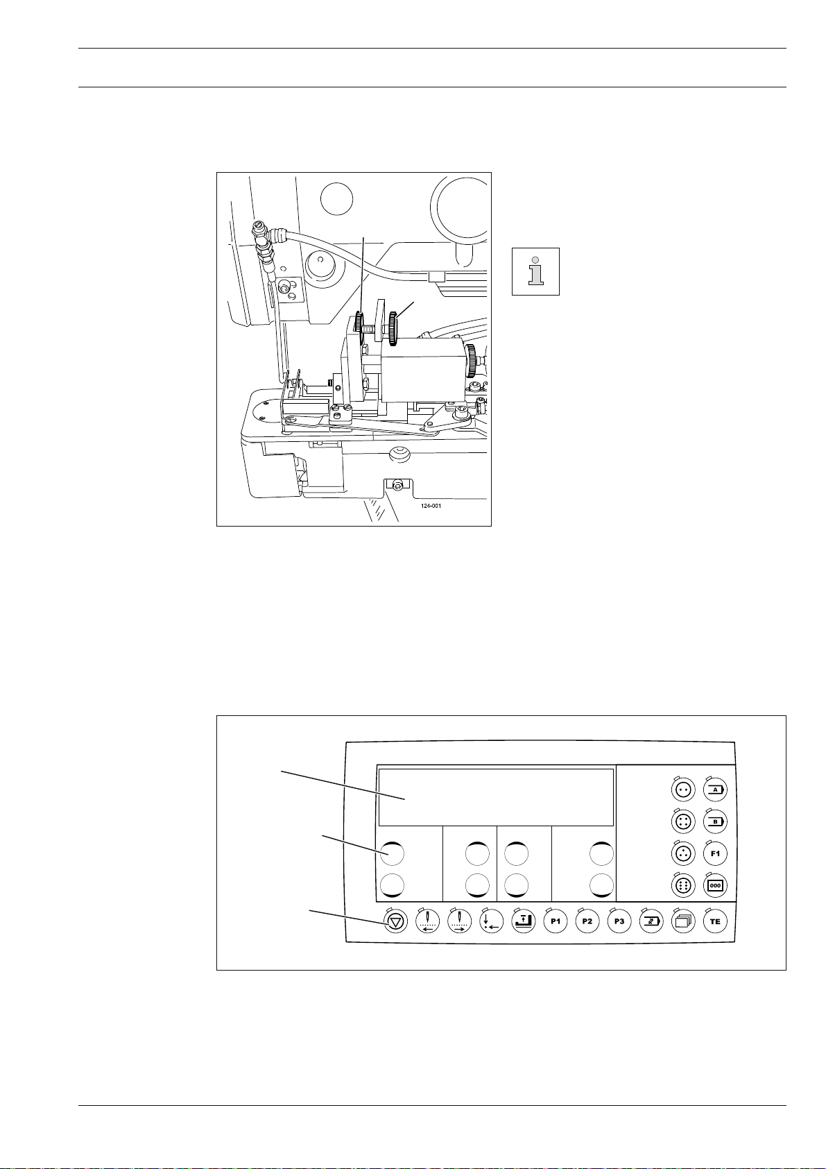
7.05 Special operating elements of the PFAFF 3307-9/01
7
.05.01 Setting the stem length
After loosening screw 1, the appropriate
●
stem length is set by turning screw 2.
1
If the stem length setting is altered, the seam pattern input
2
must be checked.
Fig. 7 - 09
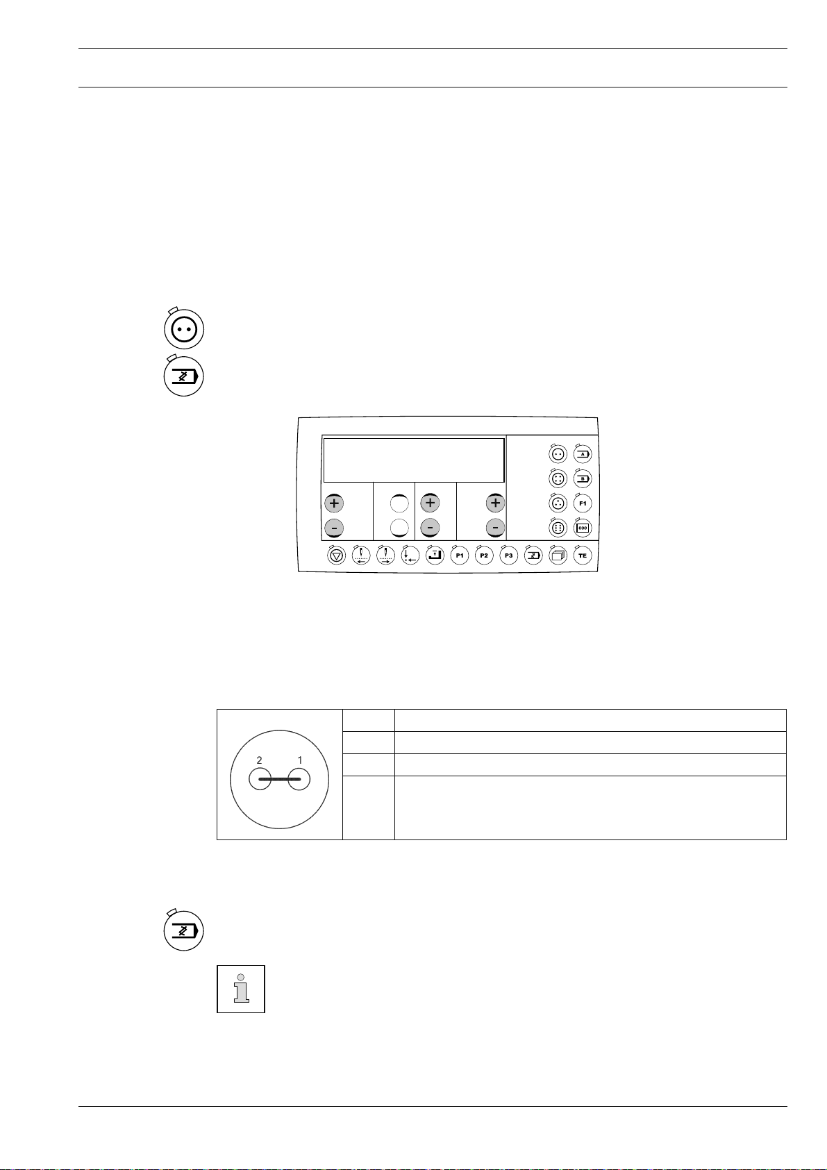
7.06 Control panel
The control panel is used to call up machine functions for setting up the machine and for
sewing operation, for entering parameter values and for reading error messages and service
settings.
1
3
2
Fig. 7 - 10
The control panel consists of the display 1 and the function keys described below. The display 1 consists of a two-line alphanumerical LCD display with 16 symbols per line. The function keys 2 are located below and to the right of the display. The status of the function keys 2
and the operating status of the machine are shown by LEDs in the respective keys.
21
Page 22
Controls
7.06.01 Screen displays
7.06.02 Display symbols
Every time the function keys 2 are operated, a key tone sounds as confi rmation of the
input. If the input required is invalid, e.g. because the max. permissible value for the
parameter input has been reached, a double tone is audible. An SD-card reader for data
transfer is integrated.
●
In the sewing mode all relevant sewing data is displayed and can be changed directly, depending on the status of the machine, see also Chapter 10 Sewing.
●
During the parameter input the selected parameter number with the corresponding value
is displayed, see Chapter 13.50 Parameter settings.
Speed Stem length
Piece counter SD-memory-card
Program number Machine memory
"Enter" function"
7.06.03 Function keys
The functions keys described below are used essentially to switch machine functions on and
off. When the function is switched on, the diode in the key is illuminated.
If a corresponding value has to be fi xed for the activated function, this can be carried out
with the corresponding +/- keys 3.
By pressing and holding the corresponding +/- key, fi rstly the numerical value displayed above it is altered slowly. If the +/- key is pressed longer, the numerical value changes more
quickly. The respective +/- keys shown opposite are described below.
Stop
●
When operated during a sewing cycle, the machine is stopped.
●
When entering the code number this key corresponds to the fi gure 1.
22
Tacting forwards
●
This key is used to tact forwards through the entire sewing cycle step by step.
●
When entering the code number this key corresponds to the fi gure 2.
Danger of needle breakage!
Before tacting move the needle to its t.d.c. using the balance wheel.
Page 23
Controls
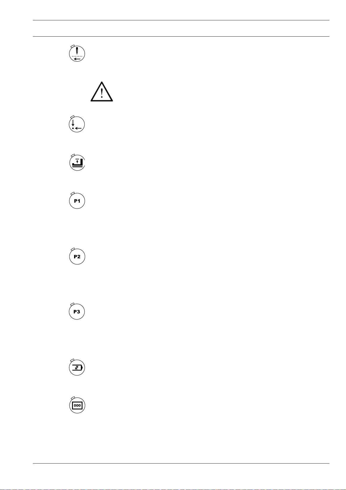
Tacting in reverse
●
This key is used to tact in reverse through the entire sewing cycle step by step.
●
When entering the code number this key corresponds to the fi gure 3.
Danger of needle breakage!
Before tacting move the needle to its t.d.c. using the balance wheel.
Basic position
●
In the sewing mode the machine moves to the basic position.
●
When entering the code number this key corresponds to the fi gure 4.
Button clamp raised/lowered
●
In the sewing mode the button clamp (or work clamp or button holder) is raised/lowered.
●
When entering the code number this key corresponds to the fi gure 5.
Direct fetch key P1
●
The direct fetch key can be allocated to a button seam pattern or a sequence. The currently selected seam pattern or the currently selected sequence is allocated to the key by
pressing this for approx. 2 sec.
●
When entering the code number this key corresponds to the fi gure 6.
Direct fetch key P2
●
The direct fetch key can be allocated to a button seam pattern or a sequence. The currently selected seam pattern or the currently selected sequence is allocated to the key by
pressing this for approx. 2 sec.
●
When entering the code number this key corresponds to the fi gure 7.
Direct fetch key P3
●
The direct fetch key can be allocated to a button seam pattern or a sequence. The currently selected seam pattern or the currently selected sequence is allocated to the key by
pressing this for approx. 2 sec.
●
When entering the code number this key corresponds to the fi gure 8.
Programming
●
This key is used to enter the seam pattern programming mode for different button types.
●
When entering the code number this key corresponds to the fi gure 9.
Piece counter
●
Press this key to reset the piece counter (LED has no function).
23
Page 24

Controls
Further functions can be selected with the keys described below, which are
each equipped with an LED. When the LED lights up, the corresponding function is activated / switched on.
Button type
●
With these keys the type of button required (two-, four-, three- or six-hole button) can be
selected.
●
On stem-wrapping machines the keys are locked.
Key A
●
This key is reserved for special functions.
●
On stem-wrapping machines the LED lights up (stem-wrapping programs are activated)
●
On blind sewing machines the sew-through with blind sewing function is activated (LED
on) or deactivated (LED off).
Key B
●
This key is reserved for special functions.
●
On blind sewing machines the blind sewing function without sewing through is activated
(LED on) or deactivated (LED off).
Key F1
●
This key is reserved for special functions.
●
On blind sewing machines the blind sewing function with material shift is activated (LED
on) or deactivated (LED off).
TE
●
This key can be used to switch between sewing operation (LED off) and input mode (LED
on). It is also used to acknowledge error messages.
24
Page 25
Mounting and commissioning the machine
8 Mounting and commissioning the machine
The machine must only be mounted and commissioned by qualifi ed personnel!
All relevant safety regulations are to be observed!
If the machine is delivered without a table, be sure that the frame and the table
top which you intend to use can hold the weight of the machine and the motor.
It must be ensured that the supporting structure is suffi ciently sturdy, even during sewing operations.
8.01 Installation
The site where the machine is installed must be provided with suitable connections for the
electric current, see Chapter 3 Specifi cations.
It must also be ensured that the standing surface of the machine site is fi rm and horizontal,
and that suffi cient lighting is provided.
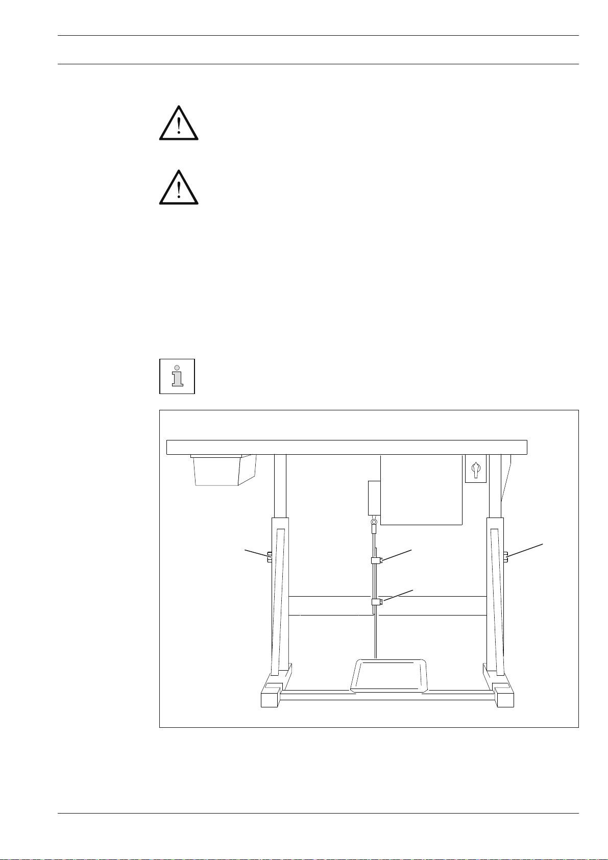
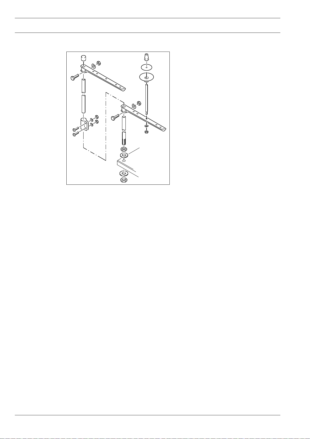
8.01.01 Adjusting the table height
For packing reasons the table top is in the lowered position. The table height is
adjusted as described below..
1
2
1
2
56-058
Fig. 8 - 01
●
Loosen screws 1 and 2 and set the table height as required.
●
Firmly tighten screw 1.
●
Set the required pedal position and tighten screws 2.
25
Page 26
Mounting and commissioning the machine
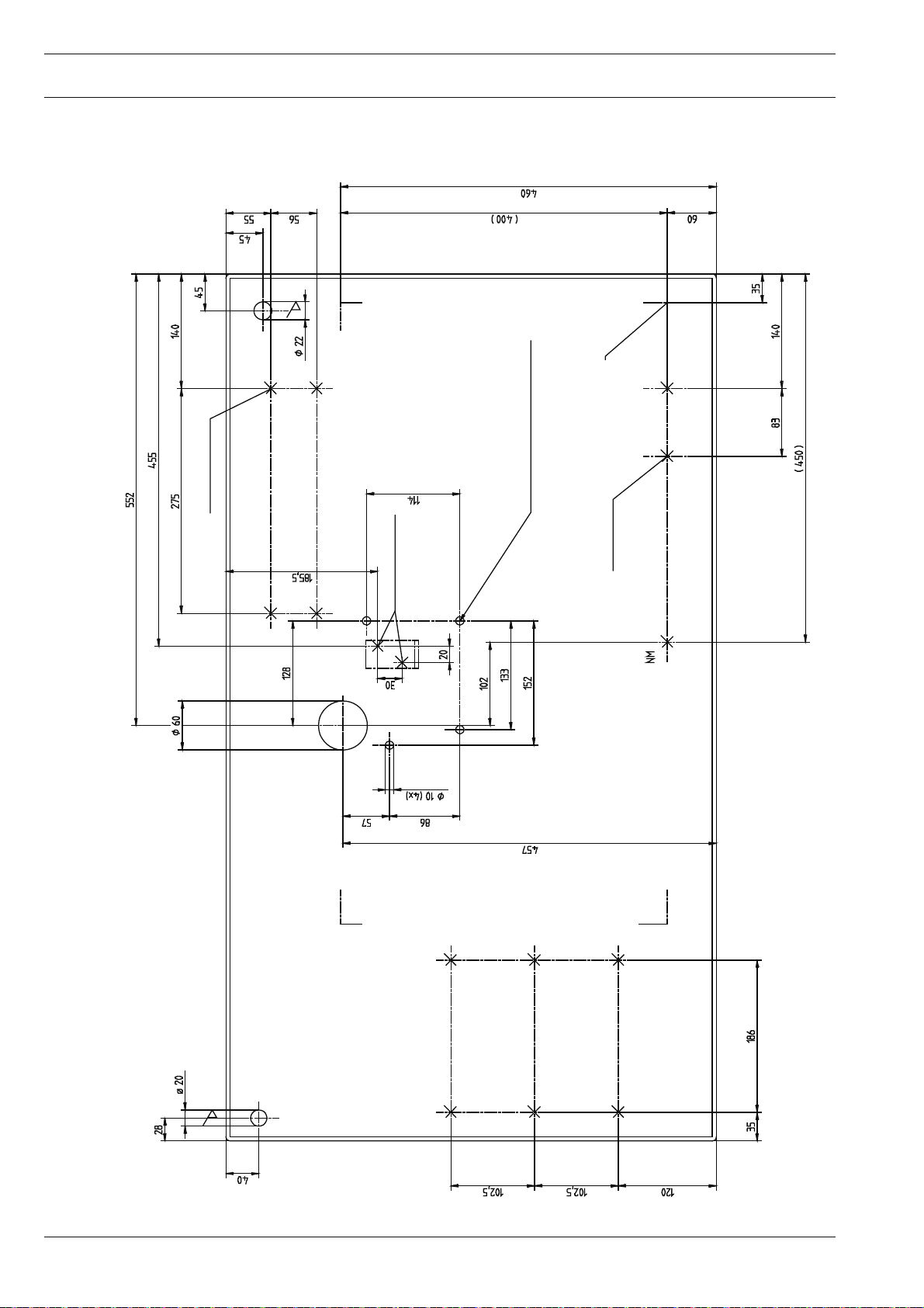
8.01.02 Drilling template for the table-top
mounting
Hole for cradle
Controlbox
unit
Speedcontrol
906-3750-000
Stand position
0 / I
26
Page 27
Mounting and commissioning the machine
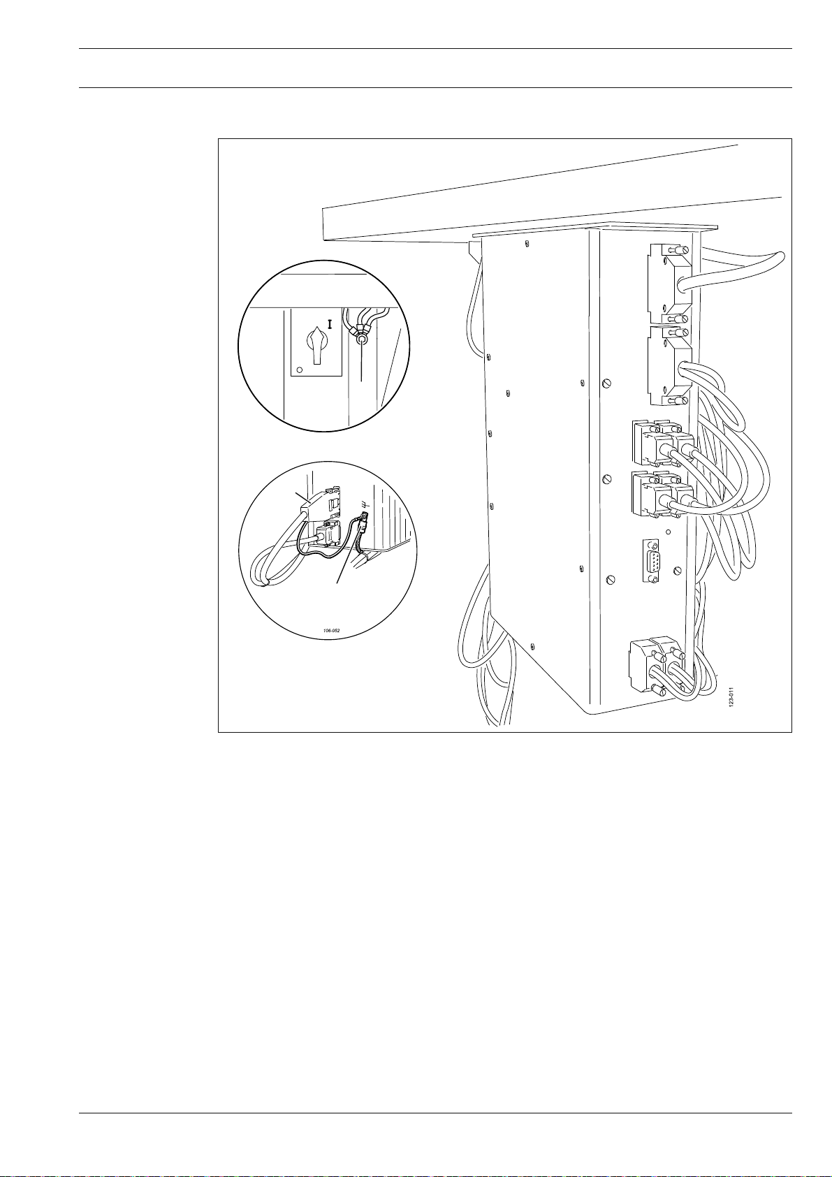
8.01.03 Connecting the plug-in connections and earth cable
106-051
A
1
B
Fig. 8 - 03
●
Connect all plugs as labelled in the control box.
●
Screw the earth cable from the machine and from the main switch to earth point A.
●
Connect earth points A and B with an earth cable.
●
Screw the earth cable of plug 1 to earth point B.
27
Page 28
Mounting and commissioning the machine
8.01.04 Fitting the reel stand
●
●
Fit the reel stand as shown in Fig. 8 - 04.
Afterwards insert the stand in the hole in
the table top and secure it with nuts provided.
Fig. 8 - 04
Fig. 8 - 04
8.02 Commissioning
●
Clean the machine thoroughly and then check the oil level ( see Chapter 12 Care and
Maintenance ).
●
Check the machine, in particular the electric leads and pneumatic connection tubes, for
any damage.
Have mechanics ensure that the machine’s motor can be operated with the available
●
electricity supply.
Connect the machine to the compressed air system. The manometer should show a
●
pressure of 6 bar.
If necessary, set this value ( see Chapter 12.05 Checking / adjusting the air pressure ).
●
Before the machine is commissioned, the seam pattern sizes set in the machine control
●
unit must be checked, see Chapter 8.04 Setting the seam pattern size.
8.03 Switching the machine on / off
28
●
Switch the machine on or off ( see Chapter 7.01 Main switch ).
Page 29
Mounting and commissioning the machine
111-009
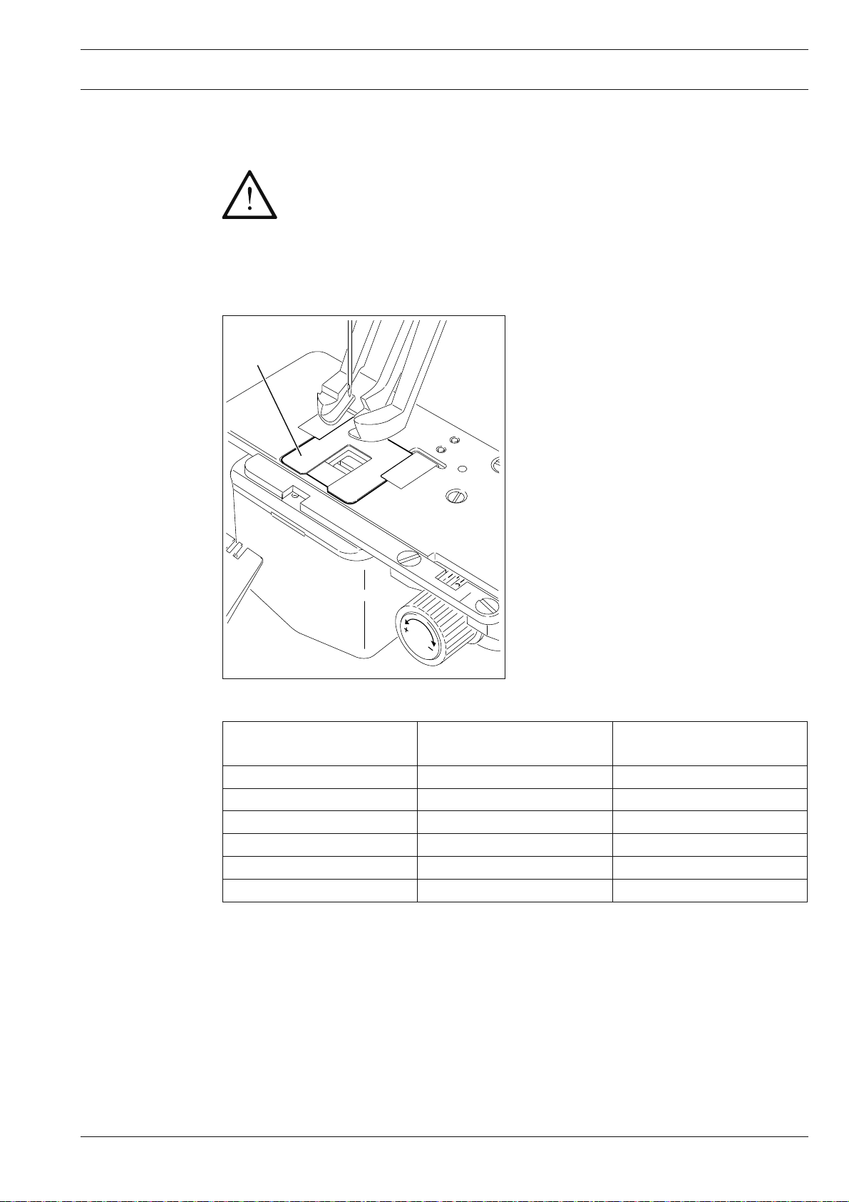
8.04 Setting the seam pattern size
After the machine has been switched on for the fi rst time, fi rst of all the seam
pattern sizes set in the machine control unit must be checked and corrected if
necessary. The seam pattern size depends on the cut-out size of the bed plate
and is set with parameter "204". If these instructions are not observed there is
a risk of severe damage to the machine!
8.04.01 Establishing the value for parameter "204"
●
1
●
●
Measure the size of the cut-out in bed
plate 1.
With the use of the table below determine the value for parameter "204".
Set „parameter "204", which is the seam
pattern size, in accordance with Chapter
8.04.02 Changing parameter "204".
Fig. 8 - 05
parameter "204"
Value for
1 7 mm x 7 mm 5 mm x 5 mm
2 8 mm x 8 mm 6 mm x 6 mm
3 9 mm x 9 mm 7 mm x 7 mm
4 10 mm x 10 mm 8 mm x 8 mm
5 11 mm x 11 mm 8 mm x 9 mm
6 10 mm x 14 mm 8 mm x 12 mm
Bed plate
cut-out size
Seam pattern size
29
Page 30
Mounting and commissioning the machine
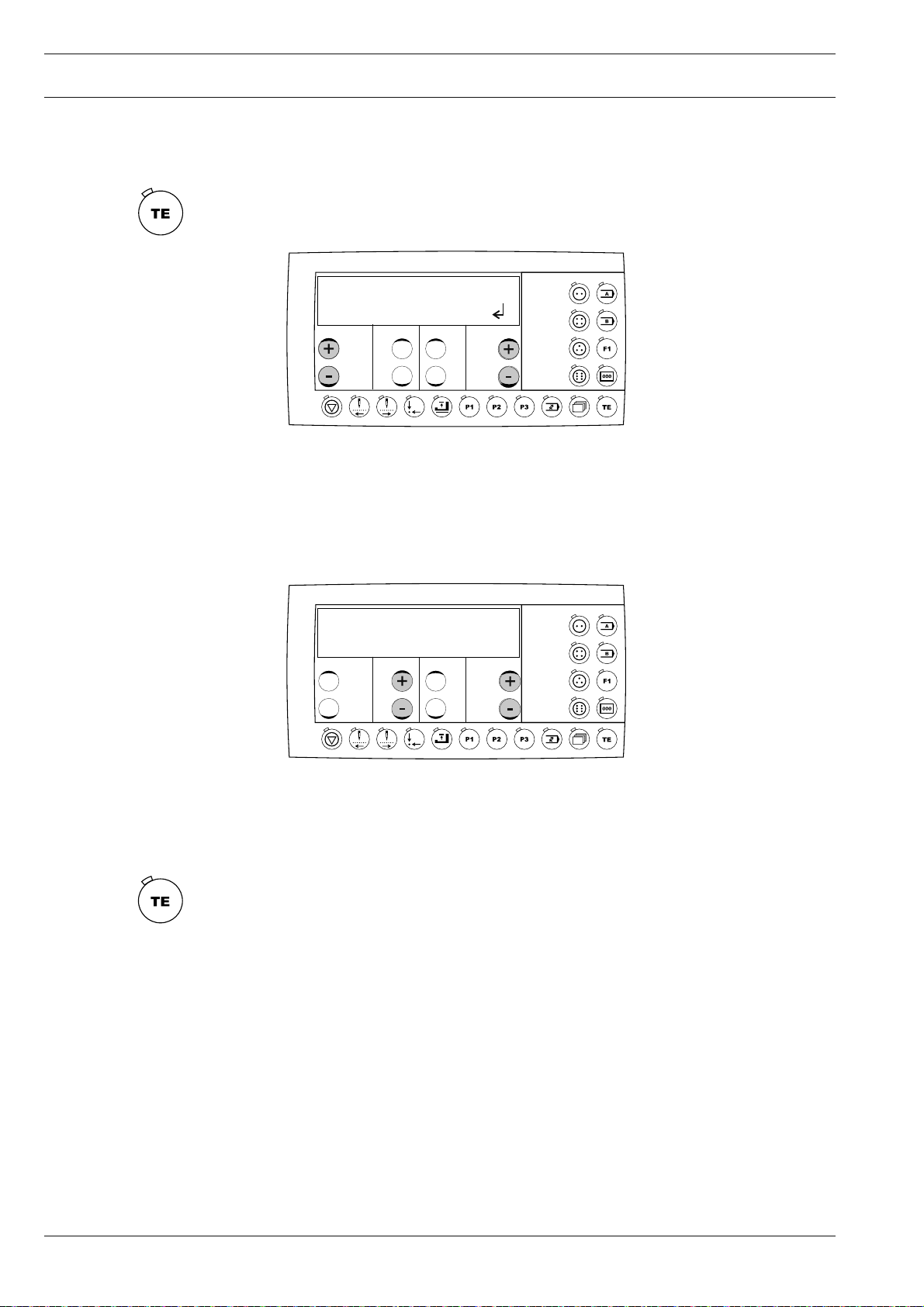
8.04.02 Altering parameter "204"
Switch on the machine.
●
Press the "TE" key to select the input mode (LED in the key is on).
●
No
200
●
Select the function group "200" by pressing the left +/- keys.
●
Confi rm the selection by pressing the right plus key.
●
If necessary enter the access code, see Chapter 13.41.02 Entering/altering the access
code.
No VAL
204 1
●
Select parameter "204" by pressing the left +/- keys.
●
Select the value calculated for the seam pattern size by pressing the right +/- keys, see
Chapter 8.04.01 Calculating the value for parameter "204".
●
By selecting the sewing mode, the altered value is taken over and the machine changes
to the sewing mode (LED in the key goes off).
30
Page 31

Setting up
9 Setting up
All instructions and regulations in this instruction manual must be observed.
Special attention must be given to all safety regulations!
All setting-up work must only be done by personnel with the necessary
training. For all setting-up work the machine must be isolated from its power
supply by turning off the on/off switch or removing the machine plug from the
electric power socket!
9.01 Inserting the needle
Switch off the machine!
Danger of injury if the machine
is started accidentally!
Fig. 9 - 01
2
1
●
Loosen screw 1.
●
Insert the needle as far as possible. The
long needle groove (see arrow) must be
facing forwards.
●
Tighten screw 1.
Through hole 2 it is possible to check whether the needle has been inserting as
far as possible.
Broken needles can be removed by inserted suitable tools in hole 2.
Only use needles from the system intended for the machine,
see Chapter 3 Specifi cations.
31
Page 32

Setting up
9.02 Threading the sewing thread
3307-3/..
1
2
3307-3/..
32
3307-9/..
3307-9/..
Fig. 9 - 02
Switch off the machine!
Danger of injury if the machine is started accidentally!
● Thread needle thread as shown in Fig. 9-02.
Page 33

Setting up
● By turning milled screws 1 and 2 adjust the tension of the needle thread to avoid material
puckering or thread breakage.
For thin, soft materials a lower thread tension is required, for thicker fabrics a
higher thread tension.
Thread the needle from the front!
9.03 Special setting-up work on the PFAFF 3307-3/..
9
.03.01 Selecting the button type and program number
To select a button type and program number, a program for the corresponding
button must already have been entered with the seam pattern input, see Chapter 11 .01 or 11.02 Seam pattern input.
● Switch on the machine.
● The sewing mode is activated automatically.
● Select the desired button type with the corresponding key.
2000 1 10 1500
● Select the desired program number (1-99), (e.g. "10"), by pressing the corresponding
+/- key.
33
Page 34

Setting up
9
.03.02 Adjusting the button clamp to the button size
●
Loosen T-screw 1.
●
Open the button clamp with sliding bar 2
and insert the button.
Move sliding bar 2 to the right and
●
tighten T-screw 1.
The button must fi t easily into
the button clamp, but without
play.
2
1
Fig. 9 -03
9.03.03 Selecting the stem length
Switch on the machine.
●
The sewing mode is switched on automatically.
2000 1 10 1500
Select the desired stem length with the corresponding +/- key:
●
Value "1" = "without stem"
Value "2" = "short stem"
Value "3" = "long stem"
34
When the short or long stem are selected, the corresponding pre-set stem
length is called up. The setting of the stem lengths is described below.
Page 35

Setting up
9
.03.04 Setting the stem length for the short stem
●
Switch on the machine.
●
Select the short stem (value "2") with the
corresponding +/- key.
●
Loosen nut 1.
●
Set the desired stem length by turning
nut 2.
●
Tighten nut 1.
2
1
Fig. 9 - 04
9.03.05 Setting the stem length for the long stem
2
1
●
Switch on the machine.
●
Select the long stem (value "3") with the
corresponding plus/minus key.
●
Loosen nut 1.
●
Set the desired stem length by turning
nut 2.
●
Tighten nut 1.
Fig. 9 - 05
35
Page 36

Setting up
9.03.06 Selecting/setting the "sew-through button attachment" function
●
Switch on the machine.
●
Call up the "sew through button attachment" function.
●
1
Set the desired penetration depth by turning adjustment wheel 1.
Fig. 9 - 06
9.03.07 Selecting/setting the "blind sewing" function
Switch on the machine.
●
Call up the "blind sewing" function.
●
●
Set adjustment wheel 1 in accordance
with the thickness of the workpiece.
36
1
Fig. 9 - 07
Page 37

Setting up
9.03.08 Selecting/setting the "blind sewing through the facing" function
Switch on the machine.
●
Press the "TE" key to call up the operating mode (LED in the key lights up).
●
No
100
●
Select the function group "100" by pressing the left +/- keys.
●
Confi rm the selection by pressing "+" on the right +/- keys.
●
If necessary enter the access code, see Chapter 13.50.02 Entering / altering the access
code.
No VAL
106 1
●
Select parameter "106" by pressing the left +/- keys.
●
Select the number of sew-through stitches by pressing the left +/- keys.
●
By calling up the sewing mode, the altered value is taken over and the machine changes
to the sewing mode (LED in the key goes off).
●
Switch on the "blind sewing through the facing" function.
To achieve the correct operation of the "blind sewing through the facing" function, the value for parameter "503/attaching stitches" must be set at "3".
37
Page 38

Setting up
111-044
9.03.09 Allocating the stem length to the seam version
Switch on the machine.
●
The sewing mode is automatically activated.
2000 1 10 1500
Select the required stem length with the corresponding +/- key:
●
Value "1" = "without stem"
Value "2" = "short stem"
Value "3" = "long stem"
Allocate the required seam version by pressing the corresponding key.
●
"sew-through button attachment"
"blind sewing"
"blind sewing through the facing"
9.03.10 Loading plate for loading stay button
1
When working with stay buttons, ex-
●
change the needle plate for an appropriate loading plate 1.
Loading plate 1 is manufactured
in accordance with customer
requirements.
38
Fig. 9 - 08
Page 39

Setting up
9.04 Special setting-up work on the PFAFF 3307-9/..
9
.04.01 Setting the stem length
Switch off the machine!
Danger of injury if the machine
is started accidentally!
1
●
Insert the button.
●
2
Loosen screw 1.
●
Turn screw 2 until the button stem is
slightly under tension.
●
Tighten screw 1.
The programmed stem length
must correspond to the actual
stem length of the button, see
Chapter 11 Input!
Fig. 9 -09
9.05 Inserting and removing the SD-memory card
Inserting the SD-memory card
●
Open cover 1.
1
●
Insert SD-memory card 2 into the card
slot with the label at the front.
●
Close cover 1 again.
2
Removing the SD-memory card
●
Open cover 1.
●
Press the edge of the SD-memory card 2
lightly – the SD-card is ejected.
●
Close cover 1 again.
3
Fig. 9 - 10
By moving slide 3 it is possible to activate (position "LOCK") or deactivate
the write protection function of the SD-memory card. To store, process or
delete data on the SD-memory card, the write protection function must be
deactivated.
39
Page 40

Setting up
9.06 Activating the sequence mode
To activate the sequence mode, the sequence must have been entered beforehand, see Chapter 11 .03 Entering a sequence.
Switch on the machine
●
Select the input mode ( LED in the key is on).
●
No
100
Call up the function group "100" by pressing the left +/- keys.
●
Confi rm the selection by pressing "+" on the right +/- keys.
●
No VAL
114 I I
●
Select parameter "11 4 " (sequence mode) by pressing the left +/- keys.
●
By pressing the right +/- keys select value "II" to switch on the sequence mode.
●
Conclude the parameter input (LED in the key goes off) by switching to the sewing
mode.
SEQ
2000 1 12 / 1 2
40
Page 41

Setting up
Screen displays:
2000: Maximum speed
The value can be changed directly with the corresponding +/- keys.
1: Stem length
The value can be changed directly with the corresponding +/- keys.
(1 = no stem; 2 = short stem; 3 = long stem)
12/1: Number of seam patterns / current seam pattern
The current seam pattern can be selected directly with the corresponding +/- key.
2: Current sequence
The current sequence can be selected directly with the corresponding +/- key.
When working through the sequences, the machine switches automatically to
the next seam pattern in the sequence after fi nishing the current seam pattern.
After the last seam pattern the machine switches back to the fi rst seam pattern
of the sequence.
41
Page 42

Sewing
10 Sewing
The machine must be installed, connected and set up in accordance with
Chapter 8 Installation and Commissioning.
The screen display on the control panel and consequently the operation of the
machine is dependent among other things on the subclass and the sequence
mode being activated, see Chapter 9.06 Activating the sequence mode.
Switch on the machine.●
2000 1 10 1500
Screen displays:
2000: Maximum speed
The value can be changed directly with the corresponding +/- keys.
1: Stem length (not on stem wrapper)
The value can be changed directly with the corresponding +/- keys.
(1 = no stem; 2 = short stem; 3 = long stem)
10: Program number
The seam pattern can be selected directly with the corresponding +/- key. In
conjunction with the four keys for button type (two-hole button, four-hole button,
three-hole button and six-hole button), for each button type 99 stored seam patterns can be selected. On the stem wrapper the stem length is selected with the
program number. Seam patterns with uneven program number have a short stem,
seam patterns with even program numbers have a long stem.
1500: Piece counter
The value can be changed directly with the corresponding +/- keys.
To set the counter at "0", press the "piece counter" key.
42
The function of the other keys and symbols is explained in Chapter
7.06 Control panel.
Page 43

Sewing
10.01 Sewing with the PFAFF 3307-3/..
Only operate the machine with
covers 1 and 2 closed!
4
Danger of injury from the movement of the take-up lever and
the hook!
1
Do not operate the machine without eye shield 3!
Danger of injury from fl ying
needle or button fragments!
3
Do not operate the machine
2
without protective cover 4!
Danger of injury from clamp
Fig. 10 - 01
drive!
Fig. 10 - 02
●
Switch on the machine, see Chapter 8.03 Switching the machine on/off.
●
Setting up the machine, see Chapter 9 Setting up.
●
Insert the button in the button clamp as shown in Fig. 10.02, and position the workpiece
as shown in Fig. 10-03.
●
Start the sewing operation, see Chapter 7.02 Pedal.
Fig. 10 - 03
43
Page 44

Sewing
Fig. 10 - 04
Danger of needle breakage!
Make sure that the button is
placed in a level position in the
button clamp!
If the button cannot be placed in a level
●
position, the button guide 1 must be appropriately re-machined.
1
Fig. 10 - 05
The machine is equipped with a missed
stitch detection function, which helps to
control the sewing process. If an error occurs, key 1 lights up. The machine start function is blocked.
Following work steps must be carried out:
●
Remove the workpiece.
●
Press key 1 (lamp goes off).
●
Cut off the button, reinsert button and
material.
●
If necessary, draw thread by pressing key
1 again.
●
Restart the sewing process.
An error signal can be caused
e.g. by an incorrectly positioned
button or by an incorrectly set
needle. If key 1 still lights up,
the machine adjustment must
be checked by qualifi ed staff.
44
Page 45

Sewing
111-048
10.02 Sewing with the PFAFF 3307-9/..
Only operate the machine with
covers 1 and 2 closed!
Danger of injury from the
1
movement of the take-up lever
and the hook!
Do not operate the machine
without eye shield 3!
3
Danger of injury from fl ying
needle or button fragments!
2
Fig. 10 - 06
●
Switch on the machine, see Chapter
8.03 Switching the machine on/off.
Setting up the machine, see Chapter
●
9 Setting up.
Insert the button as shown in Fig. 10-07.
●
Start the sewing operation, see Chapter
●
7.02 Pedal.
Fig. 10 - 07
45
Page 46

Sewing
10.03 Error messages
If a malfunction occurs, an error code appears on the display together with short instructions. In addition the diode in the memory card slot lights up red. An error message may be
caused by incorrect settings, defective elements or seam programs, as well as by overload
conditions.
For a description of the error codes see Chapter 13.51 Description of the error messages.
E009
PRESS TE
Eliminate the error.
●
Acknowledge the elimination of the error by pressing the "TE" key.
●
The diode in the memory card slot lights up yellow.
46
Page 47
Input
11 Input
11
.01 Seam pattern input on machines from subclass -3/..
For each button type (two-hole, four-hole or three-hole button) 99 programs (seam patterns)
can be entered and stored. The seam pattern input is carried out by calling up or entering
certain seam parameters. The seam pattern input is described below for each button type.
11 .01.01 Seam pattern input for two-hole and self-shank buttons
●
Switch on the machine.
●
Select the program number and button type, see Chapter 9.03.01 Selecting the button
type and program number.
Call up the programming mode
●
No X Y
P01 -10 20
Select the desired parameter (P01, P02 etc.) with the left +/- keys.
●
With the two corresponding +/- keys move to or select the desired positions (X and Y) or
●
values.
Parameter input two-hole button
P01 First needle entry position
P02 Second needle entry position
P07 Total number of stitches (1-99).
P10 End knotting function: I = off, II = on
●
Operate the left +/- keys to take over the values entered and to call up the next or
previous parameter.
Press the "programming" key to take over the values entered and to call up the sewing
●
mode.
To achieve the best results, cutting should take place at the left needle entry
position. This is achieved through the number of stitches and the location of the
needle entry positions.
47
Page 48

Input
11 .01.02 Seam pattern input for three-hole buttons
● Switch on the machine.
● Select the program number and button type, see Chapter 9.03.01 Selecting the button
type and program number.
● Call up the programming mode
No X Y
P01 -10 20
● Select the desired parameter (P01, P02 etc.) with the left +/- keys.
● With the two corresponding +/- keys move to or select the desired positions (X and Y)
or values.
Parameter input three-hole button
P01 First needle entry position
P02 Second needle entry position
P03 Third needle entry position
P07 Total number of stitches (2-99)
P09 Seam pattern:1 = seam cycle, 2 = point, 3 = basting
P10 End knotting function: I = off, II = on
● Operate the left +/- keys to take over the values entered and to call up the next or
previous parameter.
● Press the "programming" key to take over the values entered and to call up the sewing
mode.
To achieve the best results, cutting should take place at the left needle entry
position. This is achieved through the number of stitches and the location of the
needle entry positions.
Seam pattern for the three-hole button
1
Seam cycle
(P09 = 1)
3
2
48
1
Point
(P09 = 2)
2
3
1
2
Basting
(P09 = 3)
3
Page 49

Input
11 .01.03 Seam pattern input for four-hole buttons
● Switch on the machine.
● Select the program number and button type, see Chapter 9.03.01 Selecting the button
type and program number.
● Call up the programming mode
No X Y
P01 -10 20
● Select the desired parameter (P01, P02 etc.) with the left +/- keys.
● With the two corresponding +/- keys move to or select the desired positions (X and Y)
or values.
Parameter input four-hole button
P01 First needle entry position
P02 Second needle entry position
P03 Third needle entry position
P04 Fourth needle entry position
P07 Total number of stitches (2-99)
P08 Intermediate trimming: I = off, II = on
P09 Stitch formation: 1 = normal, 2 = seam cycle, 3 = arrow, 4 = Z
P10 End knotting function: I = off, II = on
● Operate the left +/- keys to take over the values entered and to call up the next or
previous parameter.
● Press the "programming" key to take over the values entered and to call up the sewing
mode.
To achieve the best results, cutting should take place at the left needle entry
position. This is achieved through the number of stitches and the location of the
needle entry positions.
49
Page 50

Input
Seam pattern examples for the four-hole button
Seam patterns with intermediate cutting (P06 = II),
without seam cycle (P09 = 1).
Seam patterns witouth intermediate cutting (P06 = I),
and without seam cycle (P09 = 1).
Seam patterns with seam cycle (P09 = 2),
the intermediate cutting function is switched off automatically.
Seam pattern "arrow" (PO9 = 3)
the intermediate cutting function is switched off automatically.
Stitch formation "Z" (P09 = 4)
the intermediate trimming function is switched off automatically.
11 .01.04 Seam pattern input for six-hole buttons
● Switch on the machine.
● Select the program number and button type, see Chapter 9.04 Selecting the button
type and program number.
● Call up the programming mode
No X Y
P01 -10 20
● Select the desired parameter (P01, P02 etc.) with the left +/- keys.
● With the two corresponding +/- keys move to or select the desired positions (X and Y)
or values.
50
Page 51

Input
Parameter input six-hole button
P01 First needle entry position
P02 Second needle entry position
P03 Third needle entry position
P04 Fourth needle entry position
P05 Fifth penetration position
P06 Sixth penetration position
P07 Total number of stitches (2-99)
P08 Intermediate trimming: I = off, II = on
P09 Seam pattern: 1 - 17 (see seam example)
P10 End knotting function: I = off, II = on
● Operate the left +/- keys to take over the values entered and to call up the next or
previous parameter.
● Press the "programming" key to take over the values entered and to call up the sewing
mode.
To achieve the best results, cutting should take place at the left needle entry
position. This is achieved through the number of stitches and the location of the
needle entry positions.
Seam pattern examples for the six-hole buttons
2
1
4
3
6
5
6
5
1
3
4
2
3
1
4
2
6
5
Stitch formation 1 (P09 = 1)
Stitch sequence 1 – 2; 3 – 4; 5 – 6
Seam patterns with intermediate cutting (P08 = II)
5
1
2
3
6
4
2
1
4
3
6
5
Stitch formation 1 (P09 = 1)
Stitch sequence 1 – 2; 3 – 4; 5 – 6
Seam patterns without intermediate cutting (P08=I)
1
4
5
2
3
6
2
1
4
3
6
5
1
2
4
3
5
6
Stitch formation 2 (P09 = 2)
Stitch sequence 1 – 2 – 3; 4 - 5 – 6
Seam patterns with intermediate cutting (P08 = II)
1
2
4
3
5
6
1
2
3
4
5
6
1
6
5
2
3
4
2
1
3
4
6
5
1
6
5
2
3
4
Stitch formation 3 (P09 = 3)
Stitch sequence 1 – 2 - 3 – 1; 4 - 5 – 6 - 4
Seam patterns with intermediate cutting (P08 = II)
Stitch formation 4 (P09 = 4)
Stitch sequence 1 – 2 – 3 – 4 – 5 – 6 – 5 – 4 – 3
– 2– 1
3
6
5
2
1
4
2
1
6
3
4
5
2
1
4
3
6
5
2
1
3
6
4
5
1
2
3
6
5
4
1
2
6
5
4
Stitch formation 5 (P09 = 5)
3
Stitch sequence 1 – 2 - 3 – 4 - 5 – 6 –1
51
Page 52

Input
Seam pattern examples for the six-hole buttons
2
3
4
1
6
5
Stitch formation 6 (P09 = 6)
Stitch sequence 1 – 2 - 3 – 4 - 5 – 4 – 1 – 6 – 1 –
4 -3 – 2 -1
2
3
4
1
6
5
Stitch formation 7 (P09 = 7)
Stitch sequence 1 – 2 - 3 – 4 – 1 - 5 – 6 – 4 – 1 –
2 - 3 – 4 – 6 – 5 - 1
2
1
6
3
4
5
2
1
4
3
5
6
2
1
3
6
4
5
1
2
3
4
6
5
Stitch formation 8 (P09 = 8)
Stitch sequence 1 – 2 - 3 – 4 – 5 – 4 – 3 – 2 -1
Stitch formation 9 (P09 = 9)
Stitch sequence 1 – 2 - 3 – 4 – 3 - 5 – 6 – 5 - 3 – 2
-1
2
1
4
3
5
6
2
1
6
3
4
5
1
4
3
2
6
5
5
4
3
6
1
2
Stitch formation 10 (P09 = 10)
Stitch sequence 1 – 2 - 3 – 4 – 3 - 5– 3 – 2 -1
Stitch formation 11 (P09 = 11)
Stitch sequence 1 – 2 - 3 – 4 - 5 – 6 – 3 – 6 - 5 – 4
– 3 – 2 -1
1
4
3
2
6
5
Stitch formation 12 (P09 = 12)
Stitch sequence 1 – 2 - 3 – 4 – 3 - 5 – 3 – 2 – 6 - 2
-1
1
3
6
2
5
4
Stitch formation 13 (P09 = 13)
Stitch sequence 1 – 2 - 3 – 2 - 4 – 2 - 5 – 2 -1
3
4
5
2
1
6
Stitch formation 14 (P09 = 14)
Stitch sequence 1 – 2 - 3 – 4 – 5 - 2 – 6 - 2 – 5 – 4
– 3 – 2 -1
1
4
3
2
6
5
Stitch formation 15 (P09 = 15)
Stitch sequence 1 – 2 - 3 – 4 – 3 - 5 – 6 – 5 – 3 –
2 -1
1
3
4
2
6
5
Stitch formation 16 (P09 = 16)
Stitch sequence 1 – 2 - 3 – 2 - 4 – 2 - 5 – 2 - 6 – 2
-1
2
1
5
3
4
3
1
4
5
2
Stitch formation 17 (P09 = 17)
Stitch sequence 1 – 2 - 3 – 4 - 5 –1
Pfaff does not guarantee that all selectable stitch formations can be sewn
reliably in all the possible needle penetration point combinations.
To achieve the best possible sewing result, the fi rst penetration point should
be at the back and the fi rst tack should be sewn in the X-direction. If necessary use the soft start function (parameter 501) for a better sewing start and add
extra stitches (parameter 503) at the seam start, or change the direction of the
formation! A reduction of the maximum speed can also improve the sewing
result.
52
Page 53

Input
11 .02 Seam pattern input on sub-class -9/.. machines
●
Switch on the machine.
●
Select the program number and button type, see Chapter 9.03.01 Selecting the button
type and program number.
Call up the programming mode
●
No X Y
P01 -10 20
●
Select the desired parameter (P01, P02 etc.) with the left +/- keys.
●
With the two corresponding +/- keys move to or select the desired positions (X and Y)
or values.
Parameter input for stem wrapping
P01 Cross stitch position material side
P02 Cross stitch position button side
P07 Total number of stitches (1-99)
●
Operate the left +/- keys to take over the values entered and to call up the next or
previous parameter.
●
Press the "programming" key to take over the values entered and to call up the sewing
mode.
To achieve the best results, cutting should take place at the left needle entry
position. This is achieved through the number of stitches and the location of the
needle entry positions.
53
Page 54

Input
11 .03 Sequence input
In one sequence up to 99 seam patterns can be stored in any order. When working with
the sequence (sequence mode) the seam patterns are processed one after the other in
the order specifi ed. After the last seam pattern in the sequence, the fi rst seam pattern is
repeated again. Below is a description of a sequence input with two seam patterns.
Switch on the machine.
●
Call up the input mode (LED in the key lights up).
●
No
100
Select the function group "100" by pressing the left +/- keys.
●
Confi rm the selection by pressing "+" on the right +/- keys.
●
No
113
Select parameter "113" by pressing the left +/- keys.
●
Confi rm the selection by pressing "+" on the right +/- keys.
●
SEQ1 SEQ
111EXIT
54
●
Select the required seam pattern by pressing the middle +/- keys.
●
Select the next position by pressing "+" on the left +/- keys.
●
Select the next seam pattern by pressing the middle +/- keys.
●
After entering the seam patterns, conclude the sequence input by pressing the right +/keys ("EXIT").
Page 55

Input
11 .04 Program Management
In the program management the program numbers of the programs fi led in the machine
memory or on the inserted SD-memory card are displayed. The programs (seam patterns)
can be deleted or copied. Commercially available SD-memory cards with a storage capacity
of max. 2 GByte can be inserted in the control panel. The machine data is stored in the
fi le "MD" in the sub-directory \P3307. The button-hole programs are fi led as follows:
The 2-hole button programs are in directory \P3307\P2 in the fi les 01 – 99.
The 3-hole button programs are in directory \P3307\P3 in the fi les 01 – 99.
The 4-hole button programs are in directory \P3307\P4 in the fi les 01 – 99.
The 6-hole button programs are in directory \P3307\P6 in the fi les 01 – 99.
The stem-wrapping programs are in directory \P3307\PU in the fi les 01 – 99.
The desired button type is selected by pressing the corresponding key. A description of how
to insert or remove the SD-memory card is given in Chapter 9.08 Inserting/removing the
SD-memory card.
Should the SD-memory cards need to be formatted on the PC, they must be formatted
in the format "FAT16". Alternatively the SD-memory cards can also be formatted on the
corresponding machine with the formatting function, see Chapter 11.04.08 Formatting the
SD-memory card.
55
Page 56

Input
11 .04.01 Calling up the program management
Switch on the machine.
●
Call up the input mode. (The LED in the key is on.)
●
Call up the program management.
●
Select the desired button type.
●
DIR
After the program management has been called up, the fi rst menu item appears (display of
programs in the machine memory).
Confi rm the selection of the menu item with the "Enter" function by pressing the right plus
key.
Scroll through the other menu items by pressing the left +/- keys, see following chapter.
The following menu items are available in the program management:
●
Displaying programs in the machine memory
●
Displaying programs on the connected SD-memory card
●
Copying individual programs to the SD-memory card
●
Copying individual programs to the machine memory
●
Deleting programs in the machine memory
●
Deleting programs on the SD-memory card
●
Formatting the SD-memory card
56
Page 57

Input
11 .04.02 Displaying programs in the machine memory
Call up the program management and select the desired button type, see Chapter
●
11.04.01 Calling up the program management.
DIR
Press the left +/- keys until the corresponding menu item appears.
●
Confi rm the selection of the menu item by pressing the right plus key.
●
DIR
01 02 40 42 END
Press "+" on the right +/- keys to scroll through the display of the machine memory
●
(programs 1 – 99). Only assigned program spaces will be displayed.
Press the left +/- keys to select the other menu items of the program management.
●
57
Page 58

Input
11 .04.03 Displaying programs on the SD-memory card
Call up the program management and select the desired button type, see Chapter
●
11.04.01 Calling up the program management.
DIR
Press the left +/- keys until the corresponding menu item appears.
●
Confi rm the selection of the menu item by pressing the right plus key.
●
DIR
01 02 40 END
By pressing "+" on the right +/- keys it is possible to scroll through the display of the
●
SD-memory card (1 – 99 programs). Only assigned program spaces will be
displayed.
Press the left +/- keys to select the other menu items of the program management.
●
58
Page 59

Input
11 .04.04 Copying programs to the SD-memory card
Call up the program management and select the desired button type, see Chapter
●
11.04.01 Calling up the program management.
COPY
Press the left +/- keys until the corresponding menu item appears.
●
Confi rm the selection of the menu item by pressing the right plus key.
●
COPY 01 02
●
Press the +/- keys under the machine memory symbol to select the seam patterns which
are to be copied from the machine memory onto the SD-memory card (programs 1 – 99).
●
Select the program numbers to be stored on the SD-memory card by pressing the +/keys under the memory card symbol.
●
Confi rm the copying process by pressing the right plus key.
●
Press the left +/- keys to select the other menu items of the program management.
If the entire contents of the machine "ALL" are selected, all the seam patterns
for the selected button type will be copied to the SD-memory card.
If a seam pattern already exists on the SD-memory card, a confi rmation enquiry
is displayed. If the right plus key is pressed, the seam pattern will be overwritten. If the right minus key or the "basic position" key are pressed, the process
is stopped.
59
Page 60

Input
11 .04.05 Copying programs to the machine memory
Call up the program management and select the desired button type, see Chapter
●
11.04.01 Calling up the program management.
COPY
Press the left +/- keys until the corresponding menu item appears.
●
Confi rm the selection of the menu item by pressing the right plus key.
●
COPY ALL AL L
●
Press the +/- keys under the memory card symbol to select the seam patterns which are
to be copied from the SD-memory card to the machine memory (programs 1 – 99).
●
Select the program numbers to be stored in the machine memory by pressing the
+/- keys under the machine memory symbol.
Confi rm the copying process by pressing the right plus key.
●
Press the left +/- keys to select the other menu items of the program management.
●
If the entire contents of the memory card "ALL" are selected, all the seam patterns for the selected button type will be copied to the machine memory.
If a seam pattern already exists in the machine memory, a confi rmation enquiry
is displayed. If the right plus key is pressed, the seam pattern will be overwritten. If the right minus key or the "basic position" key are pressed, the process
is stopped.
60
Page 61

Input
11 .04.06 Deleting programs in the machine memory
Call up the program management and select the desired button type, see Chapter
●
11.04.01 Calling up the program management.
DEL
Press the left +/- keys until the corresponding menu item appears.
●
Confi rm the selection of the menu item by pressing the right plus key.
●
DEL 0 1
●
Press the +/- keys under the machine memory symbol to select the seam patterns which
are to be deleted from the machine memory (programs 1 – 99).
●
Confi rm the deleting process by pressing the plus key.
●
Press the left +/- keys to select the other menu items of the program management.
If the entire contents of the machine "ALL" are selected, all the seam patterns
for the selected button type will be deleted from the machine memory.
The machine data "MD" cannot be deleted. Before the deleting action a confi rmation enquiry is displayed. If the right plus key is pressed, the seam pattern will be overwritten. If the right minus key or the "basic position" key are
pressed, the process is stopped.
61
Page 62

Input
11 .04.07 Deleting programs on the SD-memory card
Call up the program management and select the desired button type, see Chapter
●
11.04.01 Calling up the program management.
DEL
Press the left +/- keys until the corresponding menu item appears.
●
Confi rm the selection of the menu item by pressing the right plus key.
●
DEL ALL
●
Press the +/- keys under the memory card symbol to select the seam patterns which are
to be deleted from the SD-memory card (programs 1 – 99).
Confi rm the deleting process by pressing the right plus key.
●
Press the left +/- keys to select the other menu items of the program management.
●
If the entire contents of the memory card "ALL" are selected, all the seam patterns for the selected button type will be deleted from the memory card.
Before the deleting action a confi rmation enquiry is displayed. If the right plus
key is pressed, the seam pattern will be overwritten. If the right minus key or
the "basic position" key are pressed, the process is stopped.
62
Page 63

Input
11 .04.08 Formatting the SD-memory card
Call up the program management and select the desired button type, see Chapter
●
11.04.01 Calling up the program management.
FORMAT
Press the left +/- keys until the corresponding menu item appears.
●
Confi rm the selection of the menu item by pressing the right plus key.
●
Before formatting begins, a confi rmation enquiry is made. Press the right plus
key to confi rm the formatting process. Press the right minus key or the "basic
position" key to stop the formatting process.
If the card cannot be read, it will be completely formatted. If it can be read and
the directory \P3307 exists for the 3307, the machine data and the sub-directo-
ries for all button types in this directory will be deleted.
If the directory \P3307 does not exist for the 3307, only the directory will be cre-
ated. This ensures that programs from other machines and other fi les are not
lost.
Press the left +/- keys to select the other menu items of the program management.
●
63
Page 64

Care and maintenance
12 Care and maintenance
12
.01 Maintenance intervals
RCleaning the hook compartment .................................................................................daily
Cleaning the entire machine ............................................................................ once a week
Cleaning the air fi lter/lubricator (air fi lter) ............................................................as required
Top up oil (gears and needle drive) ..................................................................once a month
Lubricate gear shaft ........................................................................................ once a month
Checking the air pressure ..................................................................daily, before operation
During all cleaning work the machine must be disconnected from the
power supply by switching off the main switch or pulling out the plug!
Danger of injury if the machine is started accidentally!
12.02 Cleaning the machine
The cleaning cycle required for the machine depends on following factors:
●
Single or several shift operation
●
Amount of dust resulting from the workpiece
It is therefore only possible to stipulate the best possible cleaning instructions for each individual case.
For all cleaning work the machine must be disconnected from the
mains by switching off the on/off switch or by removing the mains plug!
Danger of injury if the machine suddenly starts up .
To avoid breakdowns, the following cleaning work is recommended for single shift operation:
●
Clean hook compartment and needle area of sewing head several times daily.
●
Clean the entire machine at least once a week.
64
Page 65

Care and maintenance
12.03 Cleaning the hook compartment
Switch off the machine!
Danger of injury if the machine
is started accidentally!
Open the hook compartment cover 1.
●
Clean the hook and the hook compart-
●
ment daily, more often if in continuous
operation.
1
Fig. 12 - 01
12.04 Cleaning the air fi lter/lubricator
8
6
4
50
2
0
10
100
150
12
200
14
230
0
16
2
Switch off the machine!
Remove the compressed air
tube from the air fi lter.
Empty the water tank 1:
●
The water tank 1 empties automatically
after the removal of the compressed air
tube of the air fi lter.
Clean fi lter 2:
●
Unscrew water tank 1.
●
Remove fi lter 2.
●
1
Clean fi lter 2 with compressed
air or with isopropyl alcohol
(part no. 95-665 735-91).
●
Fig. 12 - 02
Replace fi lter 2 and screw water tank 1
back into place.
65
Page 66

Care and maintenance
12.05 Checking/adjusting the air pressure
2
1
●
Before operating the machine, always
check the air pressure on gauge 1.
●
Gauge 1 must show a pressure of 6 bar.
●
If necessary adjust to this reading.
●
8
6
4
50
2
0
10
100
150
12
200
14
230
0
16
To do so, pull knob 2 upwards and turn it
so that the gauge shows a pressure of
6 bar.
Fig. 12 - 03
12.06 Top up the oil for needle drive
Top up oil once a month.
1
●
Pour in oil through the hole in inspection glass 1 up to the bottom edge of the
hole.
Only use oil with a mean vis-
2
cosity of 31.0 mm
and a density of 0.870 g/cm3 at
15° C.
/s at 40° C
66
We recommend
PFAFF sewing machine oil,
part no. 280-1-120 145
Fig. 12 - 04
Page 67

Care and maintenance
12.07 Topping up oil for the gears
Top up oil once a month.
Pour in oil through the hole in inspection
●
glass 1.
Only use oil with a mean vis-
2
/s at 40° C
Fig. 12 - 05
cosity of 31.0 mm
and a density of 0.870 g/cm3 at
15° C.
We recommend
1
PFAFF sewing machine oil,
part no. 280-1-120 145
64-015
12.08 Lubricating the gear shaft
2
1
Fig. 12 - 06
Lubricate the gear shaft once a
month.
●
Remove the cover from hole 1.
●
Use the lubricating nipple 2 of a grease
gun to lubricate the gear shaft.
Only use Gleitmo 585 M
heavy duty grease, part no.
280-1-120 269.
67
Page 68

Adjustment
13 Adjustment
13.01 Notes on adjustment
Unless stated otherwise, the machine must be disconnected from the
electric and pneumatic power supply!
All following adjustments are based on a fully assembled machine and may only be
carried out by expert staff trained for this purpose.
Machine covers, which have to be removed and replaced to carry out checks and
adjustments, are not mentioned in the text.
The order of the following chapters corresponds to the most logical work sequence for
machines which have to be completely adjusted. If only specific individual work steps are
carried out, both the preceding and following chapters must be observed.
Screws, nuts indicated in brackets ( ) are fastenings for machine parts, which must be
loosened before adjustment and tightened again afterwards.
For all the general settings in these adjustment instructions, illustrations of
the subclass -3/.. have been used, the relevant points of which can be
transferred to subclass -9/.. .
In the heading appropriate reference will be made to special settings, which
are only valid for certain subclasses.
13.02 Tools, gauges and other accessories
● 1 set of screwdrivers with blade widths from 2 to 10 mm
● 1 et of wrenches with jaw widths from 7 to 14 mm
● 1 set of Allen keys from 1.5 to 6 mm
● 1 offset screwdriver, part no. 91-029 339-91
● 1 metal ruler, part no. 08-880 218-00
● 1 C-clamp, part no. 62-111 600-35
● 1 needle rise gauge 2.4 mm, part no. 61-111 600-01
● 1 adjustment gauge "hook centre", part no. 61-11 637-03
● 1 needle plate insert gauge "needle centre" 61-111 637-09 (subcl. -9/02)
● 1 needle plate insert gauge "needle centre" 61-111 637-10 (subcl. -3/01)
● 1 button gauge, part no. 61-111 635-66
● 1 locking pin "t.d.c. needle", part no. 61-111 635-92
● 1 locking pin "needle drive", part no. 13-030 272-05
● Needles, threads and test material
68
13.03 Abbreviations
t.d.c. = top dead centre
b.d.c. = bottom dead centre
Page 69

13.04 Toothed belts of the main drive
Requirement
1. Toothed belt wheels 1 and 5 should be in alignment.
2. Hardly any play should be noticeable between toothed belt wheels 1 and 5 and the
toothed belt 6.
5
Adjustment
6
4
3
56-054
2
1
4
Fig. 13 - 01
● Adjust toothed belt wheel 1 (screws 2) in accordance with requirement 1.
● Move motor 3 (screws 4) in accordance with requirement 2.
If there are operational noises, the adjustments must be repeated.
69
Page 70

Adjustment
64-055
13.05 Top needle bar position (reference position)
Requirement
Needle bar 4 should be positioned at its t.d.c. with access to one of the screws 1.
4
3
2
1
3
Fig. 13 - 02
● Remove the needle.
● Loosen screws 1.
● Using the balance wheel, position the needle bar at its t.d.c. and lock it with locking pin
2 (part no. 61-111 635-92).
● Switch on the machine, select parameter 612.
● With screw 3 turn the motor shaft so that the value for parameter 612 is at "0".
● Confirm the value.
● Confirm the value with "Enter function".
● Tighten screws 1 (to begin with only one screw is accessible).
● Switch off he machine and remove locking pin 2.
70
This setting can change again by ± 3 increments after checking.
Page 71

13.06 Pre-adjusting the needle height
Requirement
1. When the needle bar is at its t.d.c., there should be a distance of 30 mm between
the needle point and the needle plate.
2. The thread puller 3 should be touching clamp 5 and be positioned in the centre of the
face plate cutout.
4
Adjustment
3
5
2
1
30 mm
Fig. 13 - 03
● Adjust needle bar 1 (screw 2) and thread puller 3 (screw 4) in accordance with the
requirements.
71
Page 72

Adjustment
64-105
13.07 Position of the needle to the needle hole
Requirement
When the needle bar is at its b.d.c., in the lengthwise direction of the arm the needle
should be positioned in the centre of the needle hole.
5
2
4
3
1
Fig. 13 - 04
● Switch on the machine and set parameter "610" at value "4".
● Unscrew cloth plate 1.
● Loosen screws 2, 3 and 4.
● With the balance wheel set the needle bar at its b.d.c.
● Align pendulum 5 in accordance with the requirement.
● Tighten screws 4.
● By moving the needle bar, make sure that pin 6 is not jammed and tighten screw 3.
● Switch off the machine.
Screw 2 remains loosened for further adjustments.
72
Page 73

13.08 Basic position "button clamp raised"
Requirement
When cylinder 3 is retracted completely, switch 1 should operate reliably.
Adjustment
2
3
1
Fig. 13 - 05
● Adjust switch 1 (screws 2) in accordance with the requirement.
73
Page 74

Adjustment
13.09 Sensor board of the needle drive (in dismantled condition)
Requirement
1. When parameter "610" is set at "4", the recess in eccentric 1 should match the
locking hole in the mounting bracket.
2. The switch lug of eccentric 1 should be axially centred to the hybrid light barrier of
the sensor board.
3
2
4
Fig. 13 - 06
1
5
2
6
To change the sensor board, it is imperative to observe the following work
steps!
1
74
Electric voltage!
Danger of an electric shock if handled incorrectly!
● Completely remove the needle drive unit (plugs remain connected).
● Loosen screws 2.
● Lock eccentric 1 by placing the locking pin 3 (part no. 13-030 272-05) in the locking hole
of the mounting bracket.
Page 75

Adjustment
● Switch on the machine and wait until the stepping motor has stopped running (ignore
error message on the control panel).
● Set parameter "610" at "4" (see Chapter 13.50.01 Selecting and changing
parameters).
● Making sure that it is touching the rear wall, move board 4 (screw 5) in the direction of
the arrow, until LED 6 lights up and move it back until LED 6 has just extinguished.
● Move eccentric 1 in accordance with requirement 2 and tighten screws 2.
● Switch off the machine.
● Remove locking pin 3.
● Switch on the machine and check the needle drive unit in accordance with
requirement 1.
● Switch off the machine.
● Install needle drive unit and adjust it in accordance with Chapter 13.10 Basic setting
of the needle drive.
75
Page 76

Adjustment
13.10 Basic setting of the needle drive
Requirement
With the needle bar at its b.d.c. and with eccentric 1 locked, in the crosswise direction
of the arm the needle should be in the centre of the needle hole.
1
64-077
4
2
3
Fig. 13 - 07
● Switch on the machine and set parameter "610" at "4".
● Unscrew cloth plate 1.
● Using the balance wheel, set the needle bar at its b.d.c. and lock eccentric 1
(locking pin 2, part no. 13-030 272-05).
● Adjust the needle bar frame 3 (screw 4) in accordance with the requirement.
● Remove locking pin 2.
76
Page 77

.11 Position of the hook shaft to the needle
13
Requirement
When parameter "610" is set at "1", the hook shaft should be centred to the needle.
Adjustment
1
111-019
2
Fig. 13 - 08
● Remove needle plate and cloth plate.
● Remove hook and fit hook gauge 1 (part no. 61-111 637-03).
● Loosen screw 2.
● Switch on the machine and set the parameter "610" at "1".
● Using the balance wheel, set the needle bar at its b.d.c. and set the hook gauge 1 at
the centre of the needle.
● Tighten screw 2.
● Switch off the machine and remove hook gauge 1.
The needle plate and cloth plate as well as the hook remain dismantled for
further adjustments.
77
Page 78

Adjustment
64-078
13.12 Adjusting the drag link mechanism
Requirement
When the needle bar is at t.d.c.
1. The milled slot in shaft 3 should be in alignment with the milled slot of the cast iron bracket 7.
2. The milled slot of crank 4 should be in alignment with the front edge of driving crank 6.
1
64-108
2
1
5
7
3
6
Fig. 13 - 09
● Loosen screw 1 on the arm shaft.
● Using the balance wheel, set the needle bar at t.d.c. and lock it with locking pin 2.
● Adjust shaft 3 in accordance with requirement 1 with the aid of the needle rise gauge
(2.4 mm).
● Tighten screws 1.
● Turn crank 4 (screws 5) in accordance with requirement 2.
● Remove locking pin 1.
4
78
If the position described in requirement 2 is not reached, driving crank 6
must be installed accordingly.
Page 79

64-112
13.13 Needle rise and hook clearance
Requirement
When the needle bar is positioned 2.4 after b.d.c. and parameter "610" is set at "1", the
point of hook 1 should be positioned at "needle centre" and be at a distance of 0.1 mm
from the needle.
Adjustment
3
2
1
7
5
4
6
0,1 mm
2
1
Fig. 13 - 10
● Dismount thread brake.
● Insert hook 1 so that screw 2 of collar 3 is on the surface of the hook shaft.
● Slightly tighten screw 2.
● Switch on the machine and set parameter "610" at "1".
● Turn the balance wheel in the direction of sewing until the needle bar is in its bottom
stroke.
● Fit needle rise gauge 4 (2.4 mm) to needle bar frame 5 and fasten with C-clamp 6.
● Remove the needle rise gauge 4.
● Turn the balance wheel in the direction of sewing until C-clamp 6 is touching the needle
bar bearing 5.
● Adjust hook 1 (screws 2 and 7) in accordance with the requirement.
79
Page 80

Adjustment
64-109
8
Fig. 13 - 11
● Remove C-clamp 6.
● Fit thread brake.
If the adjustment possibilities on the hook are insufficient, a greater
correction can be made with the hook shaft mechanism.
Loosen screws 8 and turn toothed belt wheel 9 or the hook shaft accordingly.
8
9
80
On the subclass -4/.. in certain circumstances it may be necessary to
increase the hook point to needle clearance to approx. 0.5 mm.
Page 81

13.14 Readjusting the needle height
Requirement
1. When parameter "610" is set at "2" and the hook point is centred to the needle, the
top edge of the needle eye should be 0.5 mm below the bottom edge of the hook
point.
2. Thread puller 3 should be touching clamp 5 and be positioned in the centre of the face
plate recess.
Adjustment
0,5 mm
56-040a
4
3
5
1
2
Fig. 13 - 12
● Switch on the machine and set parameter "610" at "2".
● Turn the balance wheel in the direction of sewing until the needle bar is at its bottom
stroke.
● Set the hook point to the centre of the needle by continuing to turn the balance wheel.
● Adjust needle bar 1 (screw 2) and thread puller 3 (screw 4) in accordance with the
requirements.
● Switch off the machine.
When checking the left needle entry position (parameter "610" at value "3"),
the distance between the top edge of the needle eye and the lower edge of
the hook point is greater.
81
Page 82

Adjustment
64-110
64-078
13.15 Adjusting the loop spreader
Requirement
1. When the needle bar is positioned at t.d.c., the milled slot in control cam 4 should be
at the bottom.
2. In the needle rise position, loop spreader 7 should begin its reverse movement.
3. When the needle is descending (in the direction of sewing) loop spreader 7 should be
at its bottom left stroke, when the needle has reached the top edge of the needle
plate.
4
5
1
6
2
3
82
3
Fig. 13 - 13
● Loosen screws 1 and 2.
● With the balance wheel set the needle bar at its t.d.c. and lock it with locking pin 3.
● Adjust control cam 4 together with control cam 5 in accordance with requirement 1.
● Move control cam 4 together with control cam 5 to touch drive wheel 6 and tighten
screws 1 and 2.
● Remove locking pin 3.
● Carry out a check in accordance with requirements 2 and 3.
Page 83

13.16 Position of the loop spreader to the needle
Requirement
When the needle bar is positioned at b.d.c. and parameter "610" is set at "3"
1. There should be a distance of 1.0 mm between the front edge of the loop spreader 1
and the needle.
2. There should be a distance of approx. 2.4 mm between loop spreader 1 and the
needle.
Adjustment
1
1
2
Fig. 13 - 14
● Switch on the machine and set parameter "610" at "3".
● Position the needle at its b.d.c. by turning the balance wheel.
● Adjust loop spreader 1 (screw 2) in accordance with requirements 1 and 2.
● Switch off the machine.
1,0 mm
2,4 mm
83
Page 84

Adjustment
13.17 Adjusting the thread trimmer on the PFAFF 3307-3/..
Requirement
1. When extended the outer edges of pins 5 and 6 should be at a distance of 103 mm
from each other.
2. When the thread trimmer is in its neutral position, the stationary knife 7 should be
parallel to the edge of thread puller 8.
3. When the thread trimmer is in its cutting position, knife 9 should cut approx. 1 mm.
3
4
5
103 mm
64-040
1
6
7
8
84
9
7
1 mm
Fig. 13 - 15
● Remove cylinder 1 (screws 2).
● Adjust hinged section 3 (nut 4) in accordance with requirement 1.
● Install cylinder 1 (screws 2) and adjust in accordance with requirement 2 and 3.
● Carry out a functional test of the thread trimmer with parameter "603" (output 4).
64-122
2
Page 85

111-022
13.18 Manual cutting test (only on the PFAFF 3307-3/..)
Requirement
In a manual cutting operation the thread should be cut reliably.
Adjustment
1
2
3
64-072
Fig. 13 - 16
● Dismount cloth plate 1 and needle plate insert.
● Place the thread between thread catcher 2 and knife 3.
● Disconnect the machine from the pneumatic power supply.
● Check the requirement by carrying out a manual cutting operation.
● Mount the needle plate, taking care to see that the spherical head of the cutting
cylinder grips into the corresponding guide section of the needle plate.
85
Page 86

Adjustment
13.19 Adjusting the thread catcher (only on the PFAFF 3307-3/..)
Requirement
In the cutting position the hook 3 should be vertical and the thread catcher 1 should grip
reliably in the stitch triangle.
1
1
3
64-079
Fig. 13 - 17
● Switch on the machine and set parameter "403" at the maximum value.
● Select the sewing mode and carry out a sewing operation.
● Switch the machine off in the cutting position at the on/off switch and disconnect it
from the pneumatic power supply.
● Carry out the cutting operation manually, checking the requirement while doing so.
● If necessary, switch on the machine and with the parameters "614" and "615" set the
thread catcher 1 in accordance with the requirement.
● If the hook 3 is not vertical in the cutting position, check the setting in accordance with
Chapter 13.05 Top needle bar position (reference position).
● Switch off the machine and check the cutting operation.
● Switch on the machine, reset parameter "402" to its initial value and switch off the
machine.
104-022
86
Page 87

111-022
13.20 Adjusting the thread loop support on the PFAFF 3307-3/..
Requirement
Both at the extreme right point of penetration and at the extreme left point of penetration
the needle should be at a distance of approx. 0.5 mm from the thread loop support 1.
Adjustment
1
2
0,5 mm
Fig. 13 - 18
● Switch on the machine and bring the needle into the relevant position (value "1, 2 or 3")
with parameter "610".
● Adjust thread loop support 1 (screws 2) in accordance with the requirement.
● Switch off the machine.
The thread loop support 1 is also used as a knife guard.
87
Page 88

Adjustment
13.21 Adjusting the spreader (only on the PFAFF 3307-9/..)
Requirement
1. The spreader 2 should be centred to the needle plate cutout.
2. When the cylinder is extended, there should be a distance of 31 mm between the pin
of yoke head 4 and the front edge of cylinder 6.
3. When the cylinder is retracted, the spreader should protrude 21 mm above the edge
of the needle plate.
2
3
111-024
1 mm
3
1
7
4
5
88
6
31 mm
Fig. 13 - 19
● Switch on the machine and set parameter "610" at value "1".
● Remove the button holder (screw 1) and the needle plate.
● Align the spreader 2 (screws 3) in accordance with requirement 1.
● Remove the needle plate insert and fit the needle plate.
● Adjust yoke head 4 (nut 5) in accordance with requirement 2.
● Adjust cylinder 6 (screws 7) in accordance with requirement 3.
● Switch off the machine.
111-026
The button holder and needle plate insert remain removed for further
adjustments.
Page 89

13.22 Adjusting the thread loop support on the PFAFF 3307-9/..
Requirement
With the needle bar at b.d.c., there should be a distance of 0.3 mm between thread loop
support 1 and the needle.
Adjustment
1
2
0,3 mm
111-027
Fig. 13 - 20
● Adjust the thread loop support 1 (screws 2) in accordance with the requirement.
89
Page 90

Adjustment
111-028
.23 Aligning the button holder (only on the PFAFF 3307-9/..)
13
Requirement
The needle bar should be centred to the hole in button holder 2.
2
1
1
3
4
90
Fig. 13 - 21
● Switch on the machine and set parameter "610" at value "1".
● Loosen screw 1.
● Adjust button holder 2 (screws 3) in accordance with the requirement.
● Move support roller 4 to make contact and tighten screws 1.
● Switch off the machine.
Page 91

111-089
13.24 Basic position of the button holder (only on the PFAFF 3307-9/..)
Requirement
With the needle bar at b.d.c., there should be a distance of 0.2 mm between button holder
1 and the needle shank.
2
Adjustment
1
0,2 mm
111-029
Fig. 13 - 22
● Switch on the machine and set parameter "610" at value "1".
● Adjust button holder 1 (screws 2) in accordance with the requirement.
● Switch off the machine.
When tightening the screws, pin 3 must be in the centre of the hole.
3
91
Page 92

Adjustment
.25 Adjusting the thread trimmer on the PFAFF 3307-9/..
13
Requirement
When the thread trimmer is in its basic position, the knife 4 should be at a distance of 2
mm from the button holder.
4
2 mm
111-031
1
Fig. 13 - 23
● Switch on the machine and connect it to the pneumatic system.
● Set parameter "508" at the values "1" / "80".
● Set parameter "510" at values "126".
● Insert yoke head 1 (nut 2) completely.
● Extend cylinder 3 (basic position).
● Adjust yoke head 1 (nut 2) in accordance with the requirement.
● Select the sewing process in order to carry out a cutting test.
● If necessary, correct the setting.
● Switch off the machine and disconnect it from the pneumatic system.
2
3
92
Page 93

Adjustment
13.26 Basic position of the button clamp drive on the PFAFF 3307-3/..
Requirement
1. After selecting parameter "610" (with value 4) it must be possible to block lever 2
with gauge (4.6 mm).
2. Switch lug 5 should be positioned in the centre of the recess of the light barrier 3.
4
6
7
5
1
2
3
8
4
Fig. 13 - 24
● Loosen screw 1.
● Switch on the machine and set parameter "610" at value "4".
● Adjust lever 2 in accordance with requirement 1 (lock with gauge).
● Tighten screw 1.
● Adjust light barrier 3 (screws 4) in accordance with requirement 2.
● With lever 2 locked, move the switch lug 5 (screws 6), until LED 7 lights up and then
move it back again until LED 7 has just extinguished.
● Switch off the machine and remove the gauge.
Spring clip 8 serves as an adjustment aid and should be touching lever 2. The
open side of the spring clip 8 should be in alignment with the clamp groove of
lever 2.
93
Page 94

Adjustment
13.27 Basic position of the button clamp drive on the PFAFF 3307-9/..
Requirement
1. After the machine has been switched on, it should be possible to lock lever 2 with
gauge (4.6 mm).
2. Switch lug 5 should be positioned in the centre of the recess of the light barrier 3.
5
6
7
3
8
1
2
4
111-035
4
94
Fig. 13 - 25
● Loosen screw 1.
● Switch on the machine.
● Adjust lever 2 in accordance with requirement 1 (lock with gauge).
● Tighten screw 1.
● Adjust light barrier 3 (screws 4) in accordance with requirement 2.
● With lever 2 locked, move the switch lug 5 (screws 6), until LED 7 lights up and then
move it back again until LED 7 has just extinguished.
● Switch off the machine and remove the gauge.
Spring clip 8 serves as an adjustment aid and should be touching lever 2. The
open side of the spring clip 8 should be in alignment with the clamp groove of
lever 2.
Page 95

13.28 Aligning the button clamp (only on the PFAFF 3307-3/01)
Requirement
After selecting parameter "610", (at the value "4") the needle should penetrate in the
centre hole of button gauge 2.
2
1
111-090
Adjustment
4
4
3
Fig. 13 - 26
● Remove loading plate 1.
● Switch on the machine and set parameter "610" at value "4" (button gauge: centre).
● Insert and align button gauge 2 (part no. 61-111 635-66).
● If necessary, correct the setting of button clamp 3 (screws 4).
● Switch off the machine.
● Remove the button gauge and fit the loading plate.
95
Page 96

Adjustment
108-130
13.29 Adjusting the clamp pressure (only on the PFAFF 3307-3/..)
Requirement
The clamp pressure is pre-set at 3 bar and may have to be adapted to the requirements.
+
-
1
Fig. 13 - 27
● Connect the machine to the pneumatic system.
● Turn regulator 1 in accordance with the requirement.
● Disconnect the machine from the pneumatic system.
96
After adjusting the clamp pressure, the alignment of the button clamp must
be checked and adjusted, if necessary, see Chapter 13.28 Aligning the
button clamp.
Page 97

13.30 Basic setting of the end knotting equipment
Requirement
Retaining finger 5 should be parallel to loop spreader 7.
7
Adjustment
6
5
7
4
111-078
3
2
1
5
Fig. 13 - 28
● Dismount cloth plate and needle plate.
● First of all remove screw 1 (nut 2), until pin 3 is touching the wall of hole 4.
● Then turn screw 1 round once and fix with nut 2.
● Align retaining finger 5 (screws 6) in accordance with the requirement.
97
Page 98

Adjustment
64-101
64-084
13.31 Adjusting the retaining finger of the end knotting equipment
Requirement
When parameter "610" is set at "1" and the machine is in the needle rise position
1. The bottom edge of retaining finger 2 should be 0.5 mm above the hook point.
2. There should be a distance of 0.5 mm between retaining finger 2 and the needle.
3. There should be a distance of 6 mm between retaining finger 2 and the centre of the
needle.
6 mm
2
3
64-102
5
6
1
4
0,5 mm
7
Fig. 13 - 29
● Switch on the machine and connect it to the pneumatic system.
● Set parameter "610" at value "1" and set needle rise position.
● Loosen screw 1.
● Adjust retaining finger 2 (screw 3) in accordance with requirement 1.
● Adjust shaft 4 (screw 5) in accordance with requirement 2.
● Switch off the machine.
● Adjust retaining finger 2 (screw 1) in accordance with requirement 3.
0,5 mm
2
2
64-100
98
When tightening screw 1 take care to see that lever 6 engages reliably in part
7 and does not block the cylinder.
Page 99

13.32 Adjusting the lifting lever of the end knotting equipment
Requirement
When parameter "610" is set at "1" and the machine is in the needle rise position, the
retaining finger 1 should be positioned 5 mm behind the centre of the needle and the
lifting lever 4 should be touching screw 2.
Adjustment
5 mm
1
4
3
2
Fig. 13 - 30
● Switch on the machine, set parameter "610" at "1" and bring the needle bar into the
needle rise position.
● Disconnect the machine from the pneumatic power supply.
● Position the retaining finger 1 by hand.
● Turn screw 2 (nut 3) in accordance with the requirement.
● Switch off the machine.
Make sure that the retaining finger 1 does not touch the loop spreader.
99
Page 100

Adjustment
64-083
.33 Adjusting the reed switch
13
Requirement
When parameter "610" is set at "1" and the machine is in the needle rise position, the
reed switch 1 should operate exactly at the moment when the tip of the retaining finger
3 is positioned at the centre of the needle.
3
1
3
2
Fig. 13 - 31
● Switch on the machine, set parameter "610" at "1" and bring the needle bar into the
needle rise position.
● Loosen screw 1 and move the reed switch 2 completely to the right.
● Place the point of the retaining finger at the centre of the needle and hold it in this
position.
● Move reed switch 2 to the left, until reaching the switch point.
● Fasten screw 1.
● Check the switch status of reed switch 2 with parameter "602" (position 4).
● Switch off the machine.
100
 Loading...