

Page 1
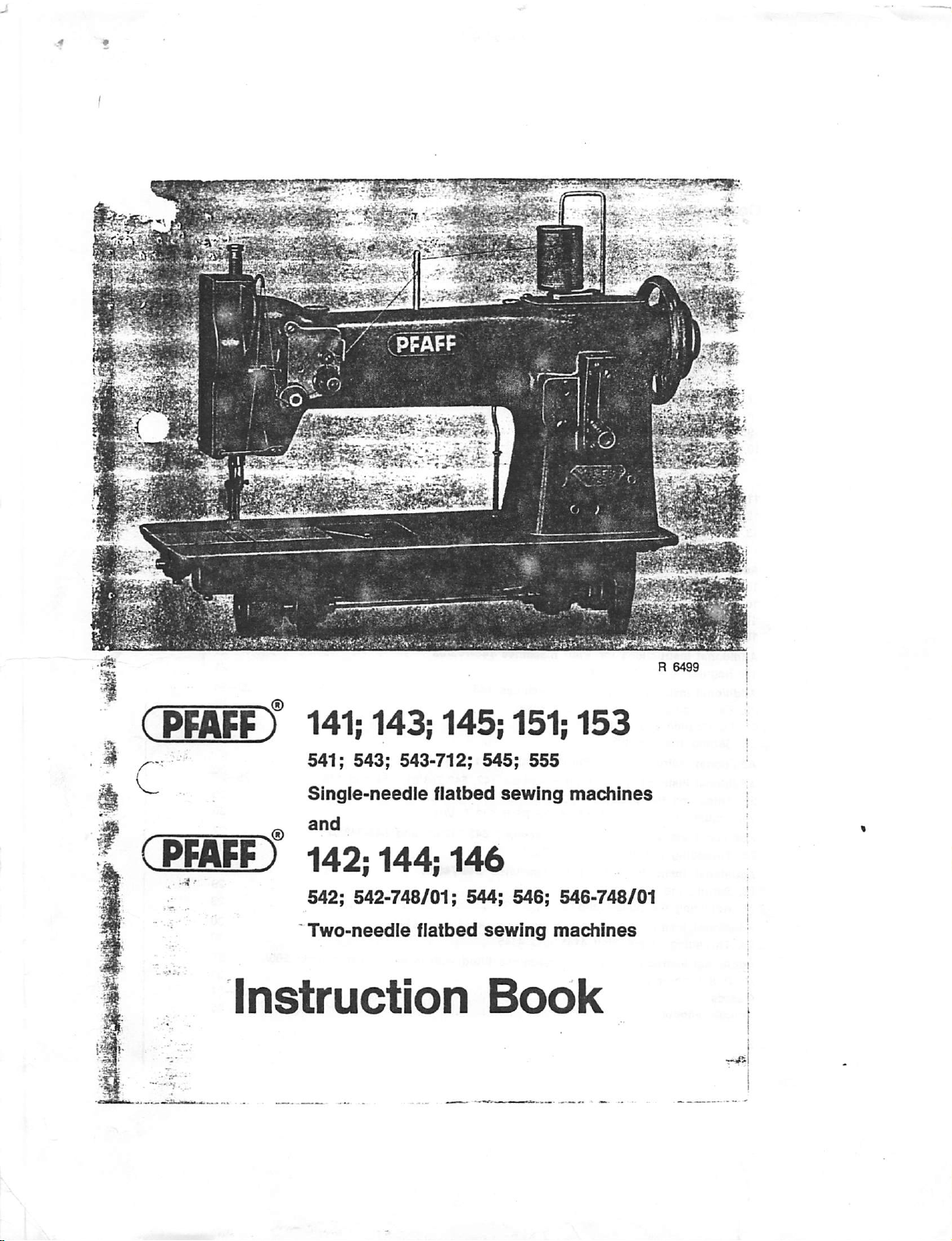
R
6499
( PMff f
Instruction
141;
541; 543;
Single-needle
142;
542;
Two-needle
143|
543-712;
144;
542-748/01;
145;
flatbed
146
flatbed
151;
545;
555
sewing
544; 546;
sewing
Book
153
machines
546-748/01
machines
Page 2
Contents
1.
General
Fundamentalsofmachine
2.
3.
Cleaning
4.
Winding
5.
Changing
6.
Selecting
Needle
Needle
Needle
7. Changing
8.
Threading
9. Drawing up the bobbin thread
10. Regulating the thread tensions
Adjusting the upper tension
Adjusting the lower tension
11. Regulating the stitch length
12.
Regulating
13. Cleaning
14.
The
Additional
15. Regulating the stitch length
16.
Changing
17. Adjusting
^18.
Operating
Additional
19.
Regulating
Additional
20.
Exchanging
21.
Lubricating
0-22. Setting
-
Additional
Additional
r23.
Threading
.
24.
Adjusting
Additional
"25. Threading the needle of the Pfaff
-.-Additional
^26.
Setting
't27.
Adjusting
^Additional
^^^28.
"
..
Threadingofthe
^
Additional
'!'29.
Pedal
Guards
Trouble
^i2
and
oiling
the
bobbin
the
bobbin
and
the
correct
systems
point
styles
and thread sizes 8
the
needle
the
needle
the
the
sewing hook
safety
clutch
instructions
the
feed
the
trimmer * *
the
trimmer
Instructions
the
Instructions
the
the
the
foot lift
Instructions
Instructions
the
the
Instructions
Instructions
the
foot
the
instructions
needle
pressureonthe
for
Pfaff
gears
for
Pfaff
stitch
length
for
Pfaff
alternating
machine
for
Pfaff
for
Pfaff
needles
puller
feedofthe
for
Pfaff
for
lift
. . . ; ^
puller
feed
for
Pfaff
Instructions
operation
shooting
for
Pfaff
operation
threading
the
bobbin
material
machines'141-705/03
machines
machines
143-705/03
145
pressers
machines
machines
151
142,
Pfaff
542-748/01
machines
543-712
Pfaff
machines
Pfaff
machines
4141
and
4145
machines
fitted
case 7
and
141-705/03-725/01
and
153
542-748/01,
543-712/01
144
and
543-712/02
and
146
546-748/01
4141
and
4145
. -
with
thread
puller/trimmer
t
' •
, ^
Page
. 16-18
22-24
25-^
...
28—29
900/».31
/
®
3
^
®
3
®
®
^
''S
'•8
^
21
21
22
24
(
25
26
27
29
30
8®
^
Page 3
t.
General
•
Since
the
operationofthe
the
general
Additional
144;
appearatthe
We
reserve
are also subject to change.
Itisrecommendedtorun
Pfaff
Pfaff
Pfaff
Pfaff
When
reducedInorderto
The
maximum
The
maximum
mentsortrimming
cause
chinescapacity.Ifthe
trimming mechanism.
To
avoid
speed
their
constant
All
machines
ba
ance
ible pulley.
If
fitted
nism
disengaged.Toengage
with
your left hand and turn the large
instructions
instructions
145;
146; 151;
backofthis
the
righttomake
141
and
144
151
and
544
153
and
542
^ 2
145
and
541
sewing
tightly
compiledinthis
for
153;
woven
prevent
speedoftwo-needle
the
natureofthe
speeds
which
mechanisms
work
maximum
troubleinthe
until
the
action
upon
use.
parts
are
regularly
each
which
other.
mechanism,
wheel.Ifdesired,
with
the
latter
type
machines
the
552-748/01;
booklet.
listedonthe
Pfaff
141-705/03;
543-712/..;
alterations
these
machinesatthe
3
000
s.p.m.
2
900
s.p.m.
2
800
s.p.m.
2
700
s.p.m.
2
600
s.p.m.
500
s.p.m.
2
400
s.p.m.
2
300
s.p.m.
and
heavily
overheating
dressed
machines
canbeattained
are
often
and
the
thicknessofthe
speedisexceeded,
run
areinmovable
This
should
equipped
however,
pulley,
this
withafixed
these
the
machineisdispatched
mechanism
lock
title
pageismoreorless
book
applytoallofthem.
141-705/03-725/01;
546-748/01;
serving
of the
progress.
following
Pfaff
4141
Pfaff
545
Pfaff
546
Pfaff
546
Pfaff
545
Pfaff
4145
Pfaff
546
and
543-712/..
materials,
needle.
The
H3
H2
H3
H4
H4
the
decreasesasthe
with
machines
far
below
the
recommended
material
trouble
the
machineatabout75per
contact
normallybethe
machines
nut
have
pulley
canbesupplied
for
sewing,
clockwise.
become
case
whichiscastinone
hold
142;
4141;
4145
illustrationsinthis
top
speeds:
sewing
needle
fitted
may
speed
gauge
with
top
tendtolimit
develop
thoroughly
after
about
withadisengage-
with
the
sewing
the
balance
the
143-705
and
-900'..
2
200
2100
1
300
i
800
i
700
1
600
1400
should
increases.
special
attach
speeds
the
chieflyinthe
centofits
glazed
two
weeks'
with
mecha
wheel
steady
same
03-
book
s.p.m.
s.p.m.
s.p.m.
s.p.m.
s.p.m.
s.p.m.
s.p.m.
be
be
ma
top
by
the
2. Fundamentals of machine operation
Before
you
put
the
which
has
accumulatedintransit
on
the
machine
Checktomake
Never
runathreaded
vibrating
Before
presser.
you
start
machineinoperation
only
with
Pfaff
sewing
sure
the
finger,
take-up
machine
sewing,
lay
both
and
unless
threads
for
oil
the
machine
machine
lever
you
have
back
the
first
time,
carefully
thoroughly
oil
whichIsnon-resinous
and
belt
fabric
under
guards
the
are
under
presser
(see
properly
the
presser
foot
remove
Chapter
and
fitted.
footorthe
all
dust
3).
acid-free.
Page 4
To
prevent
stitches. . „
Do
not
Use needlesofthe correct
Never
Use high-quality threads
Always
pull
use
bring
thread
the
material
rusty
needles.
the
jamming,
during
system
only.
take-up
levertoits
hold
sewing:
both
only
highest
thread
ends
the
machine
(see Chapter
point
until
the
wiil
6).
before
machine
feed
the
you
remove
has
madeafew
fabric
automatically.
the
material.
3. Cleaning
Careful
After
you
a
clean
few
dropsofkerosenetoall
raise
the
run
briefly.
of
friction.
While
these
oiled
each
oilhoie R (Fig. 4).
Althougti
itisrecommendedtoreplace
year.
Owingtothe
gear teeth
and
cleaning
rag
and
have
removed
and
presser
remove
foot,
Applyafew
pointsoffriction
day
the
machineisin
the
bevel
shouldbegreased
oiling
regular
the
the
unthread
dropsofPfaff
geers
ere
special
oiling
will
Increase
dust
which
has
grease
from
oiling
points
the
needle,
sewing
shouldbeoiled
operation.
enclosedinceses
the
old
greasebyPfaff
lubricating
only
propertiesofthis
lightly.
the
service
accumulatedonthe
all
nickel-plated
marked
remove
with
the
machine
twiceaweek,
Make
particularly
and
and
dash
bobbin
oil
No.
requirenospeclel
grease
grease,
lifeofyour
machine.
machineintransit,
polished
Parts.
linesinFigs.1.2
case
and
let
the
280-1-120122toall
the
sewing
sure
hook
that
oilisapplied
mamtenence.
the
flanksofthe
take
Apply
a
and
3.
J^achine
points
"lUSt
be
to
once
a
beve
Page 5
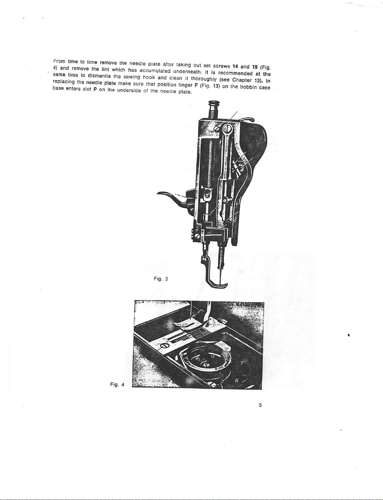
^rom
timetotime
remove
the
needle
plate
alter
taking
out
set
sorevvs14andisrpi.
repT
^-Tng'tortnd
jse::Lrs,rrhi\rr3ror.t~
dearnhTrougWy
(sarcTaTte?
13')
^ -
7n
Page 6
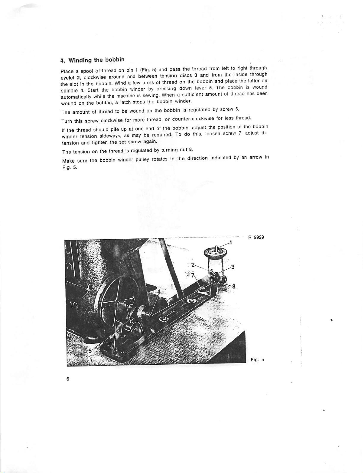
4. Winding
the
bobbin
Placeaspoolofttfreadonpin1(Fig.5)and
eyelet2,clockwise
the
slotinthe
spindle4.Start
automatically
wound
The
Turn
on the
amountofthreadtobe
this
screw
If
the
thread
winder
tension
tension and tighten the set screw again.
The tension on the thread is
Maks
sure
the
Fig.
5.
around
bobbin.
the
while
the
bobbin,alatch
clockwise
should
and
between
Windafew
bobbin
turnsofthreadonthe
winderbypressing
machineissewing.
stops the
woundonthe
for
more
thread,orcounter-clockwise
pileupat
one
endofthe
tension
Whenasufficient
bobbin
sideways,asmayberequired.Todo
regulatedbyturning
bobbin
winder
pulley
rotatesinthe
pass
the
thread
from
lefttoright
discs3and
down
from
bobbin
and
lever5.The
the
place
bobomiswound
amountofthread
winder.
bobbinisregulatedbyscrew
lor
less
bobbin,
adjust
this,
nut 8.
direction
the
positionofthe
loosen
screw7,adjust
Indicatedbyan
inside
the
has
6.
thread.
through
through
latter
on
been
bobbin
th.
arrow
R
9929
in
Page 7
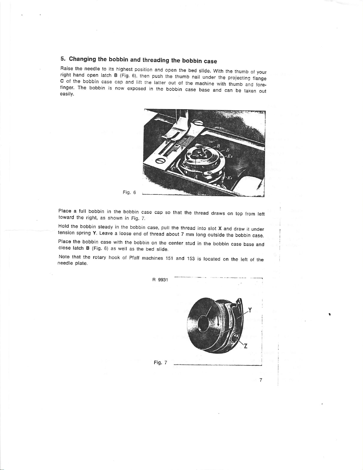
5. Changing the bobbin and threading the bobbin case
Raise
the
right
hand
Cofthe
finger.
easily.
needletoits
open
bobbin
The
bobbinisnow
highest
latchB(Fig.
case
cap
and
exposedinthe
position
6),
then
lift
the
and
push
latter
open
the
the
thumb
outofthe
bobbin
bed
nail
case
slide.
under
machine
base
With
the
the
projecting
with
thumb
and
canbetaken
thumbofyou:
flange
and
fore
out
Placeafull
toward the right, as shown in
Hold
the
tension
Place
close
Note
needle
bobbininthe
bobbin
steadyinthe
springY.Leavealoose
the
bobbin
latch B (Fig. 6) as well as the bed slide.
that
the
plate.
case
rotary
bobbin
Fig.
bobbin
with
the
hookofPfaff
case
capsothat
7.
case,
pull
endofthread
bobbinonthe
machines
R
9931
the
the
thread
about7mm
center
studinthe
151
and
153islocatedonthe
thread
into
long
drawsontop
slotXand
outside
the
bobbin
case
from
left
drawitunder
bobbin
case.
base
and
leftofthe
Page 8
6.
Selecting
To
ensure
the
machine.
Needle
The
134
for
34
for
with
134-35
systems
following
Pfaff
smaller
the
reliable
needie
Pfaff
machines
machines
holes
for Pfaff
555H3and
134 FLQ for Pfaff
gauges
134
KK
for
the
134
RER
and
134
190
for
the
Pfaff
Needle
point
styles
These
needles
various
134
R.
Fabrics
needles
LR
LL
LACK
P
PGR
POL
S
D
VR
VL
Rubberized
needle
are
are
%
m
m
m
m
1
#
9
fabrics
are
stitched
available
correct
stitch
formation,
systems
141, 142,
142; 144;
(shank
size
machines
4141
machines
from
1.6to2.2
Pfaff
153.
REL
for
543-712/...
available
point
styles
witharound-point
with
Narrow
Narrow
Patent
Extra-narrow
Extra-narrow
Extra-narrow
Narrow
Triangular
Reverse
Twist
and
reverse
twist
leather
cross
twist
spear
plastic
needle
checktosee
are
used
for
143,
144. 151. 541,
542
and
544,
1.65
mm).
142-732/09, 142-732/11, 145 H3, 146 H3, 545 H3, 546 H3,
142-720/01-6/01, 142-721/01-6/01
mm
inclusive.
the
Pfaff
546
H2.
545
H4.
546
H4.
with
are
different
identified
type
needle,
the
following
twist
stylesofpoints:
point
point
point
wedge
point
wedge
point
wedge
point;
point;
spear
for
point
for
short,
point
long,
point
materials
are
that
the
individual
542,
when
these
555
H4.
pointstosuit
by a
letter
identified
with
right-twist
with ieft-twist
straight
straight
sewn
stitches
with
the
correct
machine
543
and
machines
and
4145
different
following
by R,
groove
groove
stitches
round-point
needleisinserted
classes:
544.
have
and
144-720/01 in
H3.
requirements.
the
needle
while
needles.
needle
for
holders
system,
leather
in
needle
The
e. g.
work
Needle
and
thread
sizes
The
correct
sults.
through
hundredths
a
select
the
needle
the
ofamillimeter.
sizeisdependent
needleasthin
needle
eye
easily.
as
The
on
possible,
needle
the
fabric
but
size
and
make
(Nm) is
thread
sure
weights.
the
thread
indicated
For
canbepulled
on
the
shank
best
re
in
Page 9
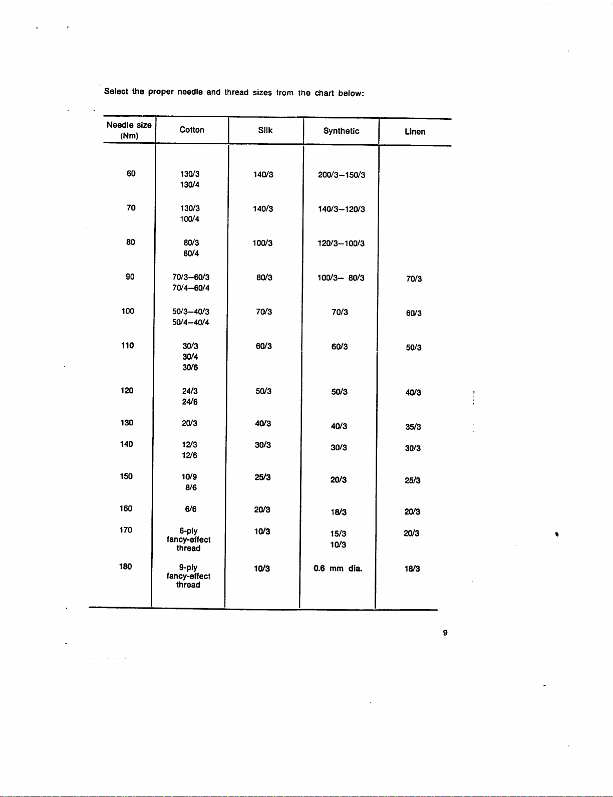
Select
Needle
(Nm)
the
size
proper
needle
Cotton
and
thread
sizes
Silk
from
the
chart
Synthetic
below:
Linen
100
110
120
130
140
SO
60
70
60
130/3
130/4
130/3
100/4
80/3
80/4
70/3-60/3
70/4-60/4
50/3-40/3
50/4-40/4
30/3
30/4
30/6
24/3
24/6
20/3
12/3
12/6
140/3
140/3
100/3
80/3
70/3
60/3
50/3
40/3
30/3
200/3-150/3
140/3-120/3
120/3-100/3
100/3-
70/3
60/3
50/3
40/3
30/3
80/3
70/3
60/3
50/3
40/3
35/3
30/3
150
160
170
180
10/9
8/6
6/6
6-ply
fancy>effect
thread
9-ply
fancy-effect
thread
25/3
20/3
10/3
10/3
0.6
20/3
18/3
15/3
10/3
mm
dia.
25/3
20/3
20/3
18/3
Page 10
The
needle
machine
ModelA:Needle
Model
Model
Model
The
needle
needle
7.
Changing
Raise
pull
the
Insert a new
sewing hook.
securely.
Never
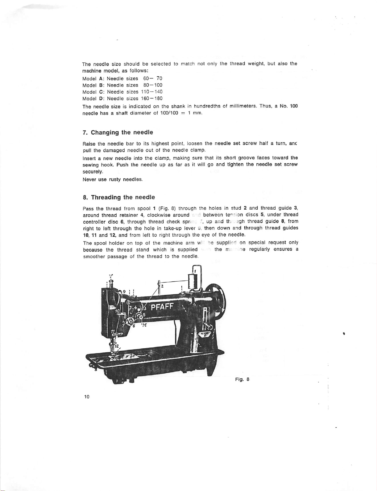
8.
Threading
Pass
around
controller
size
model,
B:
Needle
C:
Needle
D:
Needle
sizeisindicated
hasashaft
the
needle
damaged
use
rusty
the
thread
thread
disc
should
as
the
needle
Push
needles.
the
retainer4,clockwise
6, through
follows:
sizes
sizes
sizes
sizes
diameter
bar
needle
from
needle
to its
into
the
needle
spool
be
selected
60—
80—100
110—140
160—180
on
of
highest
outofthe
the
clamp,
needle
1 (Fig. 8)
thread
to
match
not
only
the
thread
70
the
shankinhundredths
100/100
point,
needle
= 1
loosen
making
mm.
clamp.
sure
the
that
of
needle
its
short
millimeters.
up as far as it will go and tighten
through
around
the
holesinstud2and
between
te'"'ion
check spri up and th igh
weight,
set
screw
groove
the
discs5,under
thread
but
also
Thus,
a No.
half a turn, anc
faces
toward
needle
thread
guide
set
guide
screw
thread
8, from
right to left through the hole in take-up lever j. then down and through thread guides
10, 11
and
12,
and
The spool
because
smoother
from left to
holder
on top of the machine arm w'
the
thread
passageofthe
stand
right
through
which is
threadtothe
supplied
needle.
the
eyeofthe
">6
suppli'^'f on
the
needle.
m
le
special
regularly
request
ensures
only
the
100
the
3,
a
Page 11
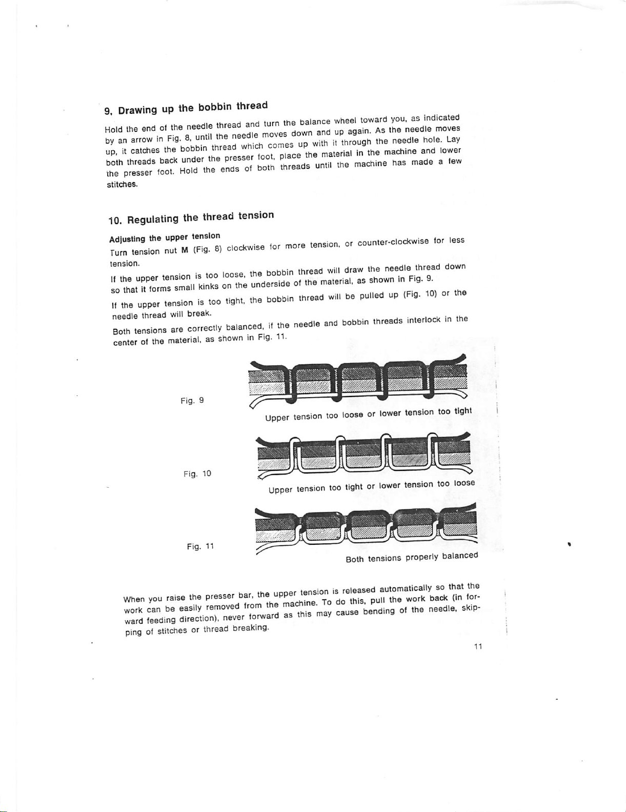
9,
Drawingupthe
HCd
t.e
endott.e
bobbin
needle
thread
thread
rp;^rr:f.r:'.:e\r:.c.co..
^ trne\V.~
r;:;Tr.rorHoTd".h?e:crr:;p°;'
stitches.
10.
Regulating
Adlustlng
Turn
^or
„
the
tension
r.Tr:iv:.ra
,ne
upper
:::r::
centerofthe
the
thread
upper
tension
nutM(Fig.8)clockw.se
tension
re
.ensionis.00
r.,—•
material,asshownmF.g.
.iph.,
.treads
for
K^Khin
unde.s.de
.he
hobbln
more
thread
o.
.he
.hread
un,,,
tens.on,
will
.a.eda,.
winbepu.ledup(Fig.
-
11.
upper
tension
too
.he
.achma
counter-clockwise
draw
as
looseorlower
has
the needle thread
shown
.adea.a«
tor
,n
^.
10)
tension
down
too
less
tight
Fig. 10
Fig.
11
=».s
pingofstitchesorthread
rcrr
tension
jliCZJ
too
tightorlower
Both
-:rsr,vrr."-r
.r«s
breaking.
r-™
™—•
tensions
tension
properly
too
loose
balanced
«•
Page 12
Adjusting
Take
(Fig.7)with
er
The
when
If
puckering
ease
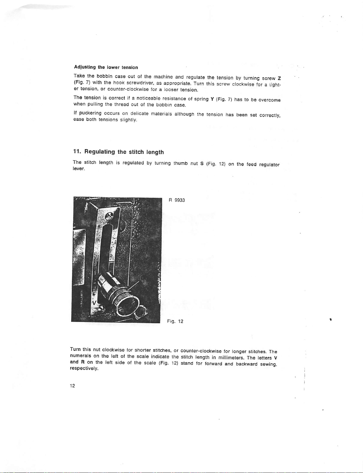
11. Regulating the stitch length
The
lever.
the
lower
tension
the
bobbin
tension,orcounter-clockwise
tensioniscorrectifa
pulling
the
the
case
outofthe
hook
screwdriver,asappropriate.
noticeable
thread
outofthe
occursondelicate
both
tensions
stitch
lengthisregulatedbyturning
slightly.
machine
foralooser
bobbin
materials
and
regulate
tension.
resistanceofspringY(Fig.7)has to be
case.
although
thumb
R
9933
the
Turn
this
the
tension
nutS(Fig.
tensionbyturning
screw
clockwise
has
been
set
12)onthe
feed
screw
foratight
overcome
correctly,
regulator
Z
s
Fig.
12
Turn
this
nut
clockwise
numerals on the left of the scale Indicate the
andRon
respectively.
the
left
for
shorter
sideofthe
stitches,orcounter-clockwise
stitch
lengthinmillimeters.
scale
(Fig.
12)
stand
for
forward
for
and
longer
The letters V
backward
stitches.
sewing,
The
Page 13

All machines with the exception of the Pfaff 141-705/03
with
a spring-return feed regulator. This device incorporates a spring
holds the feed regulator lever down in forward feeding position. When the lever is
pushed up as far as it
the
leverisreleased,
If
desired,
the
the
machine
directionoffeed
will
go, the machine
forward
can
by foot
sewing
willberesumed
be fitted with a
action.
will
pedal
and
143-705/03
sew in reverse. And conversely, when
instantly.
which
makesitpossibletoreverse
are
regularly fitted
which
permanently
12. Regulating the pressure on
The amount of pressure to be exerted by the
terial to be sewn. The pressure is set correctly if the material is advanced through the
machine evenly without being injured by the teeth of the feed dog.
The pressure on the
in for
more
pressure,
Depending
on the
material
or out for
version,
is regulated by turning screw V
Pfaff
less
145,
the
material
pressure.
146,
545.
presser
546
and
foot must be adapted to the ma
(Fig.
8).
Turn
this screw
555
machines
are
equipped
with
one or two leaf springs on the machine arm instead of the conventional presser bar
spring
with
pressure
increased by
downwards.
turning
regulating
knurled
screw.Onthese
nut V
(Fig.
13)
machines
upwards,
the
presser
foot
and decreased by
pressure
turning
Is
It
Fig.
13
Page 14

13.
Cleaning
The
sewing
shouldbecleaned
highest
out
wheel until point S of
the
point,
three
the
sewing
hookIsthe
thoroughly
open
the
screws
most
bed
Ei, Ej
the
hook
essential
from
slide
and
bobbin
(Fig. 14). When in this position, the
ing
center
stud
Z with
thumb
and
forth
lightly.
Clean
hook
and
hook
(Fig. 14)
soaked
should
with
oil.
have
raceway
become
thoroughly with
matted,itshould
partofthe
timetotime.
and
remove
Es (Fig. 6)
case
bobbin
and
baseisabouttoenter
case
forefinger while
be
whole
machine
To do
this,
the
bobbin
case
strip
the
hook
base
canbetipped
turning
the
kerosene.Ifthe
replaced
and
raise
balance
the
and.
the
with
gib.
groove
out
cotton
new
for
this
needle
bar
the
bobbin.
Turn
the
N of
the
easily by
wheel
back
wool in slot 0
cotton
reason,
to its
Take
balance
hook
seiz
and
wool
be
Fig. 14
To clean the parts in the vicinity of the sewing hook, take out set screw 20 (Fig. 4) and
pull the hook up out of the machine. When the hook is replaced, pin 19 (Fig. 4) ensures
proper positioning and eliminates the
need
of retiming the hook.
In replacing the bobbin case base, make sure that position finger F (Fig. 14) enters slot
P on the underside of the needle plate. Replace hook gib and tighten screws Ei -
Ej. Put a drop of oil Into the hook raceway, replace the bobbin
and
close
latch B (Fig. 6).
Never run the machine
the bobbin
case
with
or the bobbin
the needle plate removed as this may result in damage to
case
opener.
case
with the bobbin
The above Instructions also apply to all two-needle sewing machines covered by this In
struction
Book.
Page 15
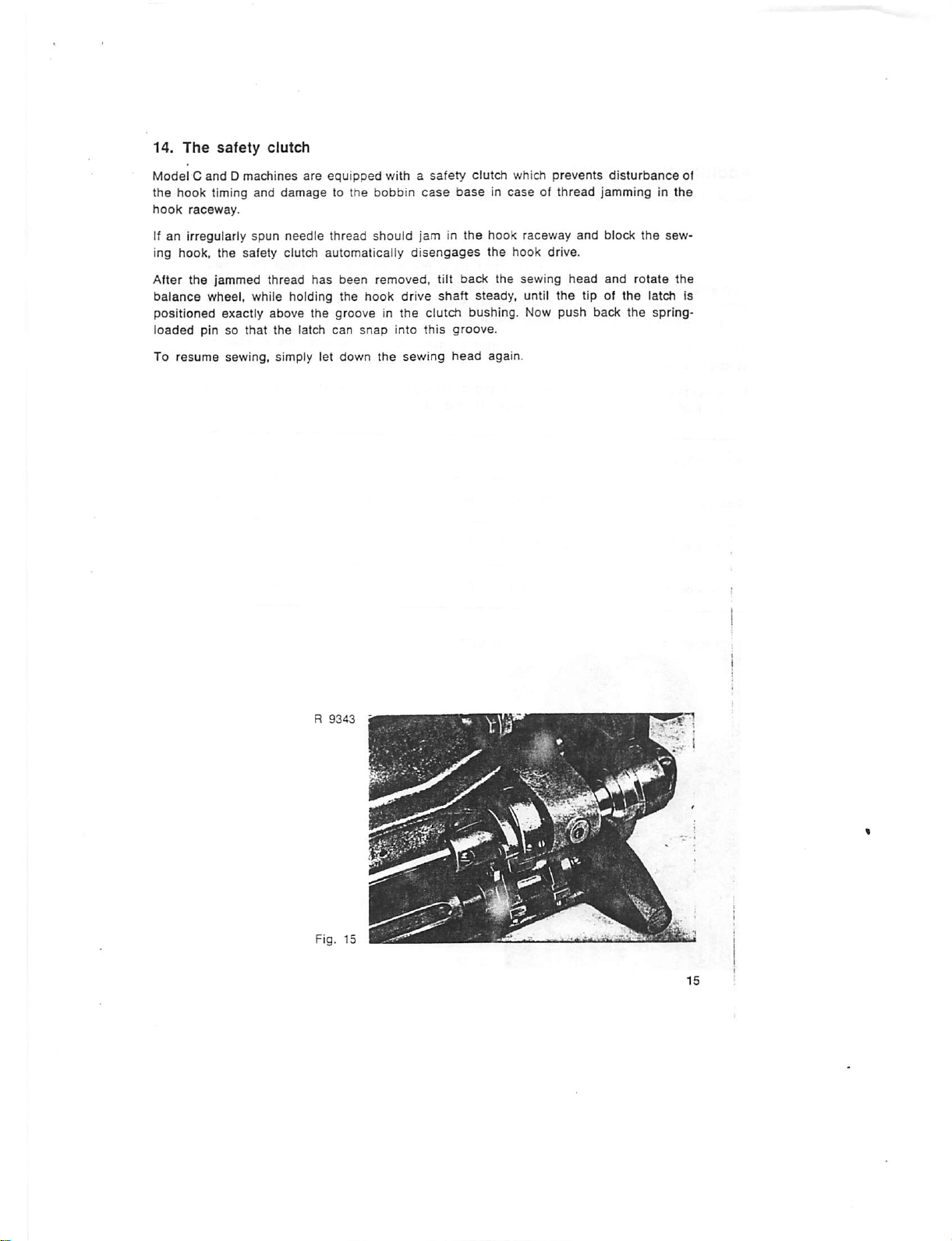
14.
The
safety
clutch
ModelCandDmachines
the
hook
timing and
hook
raceway.
If an irregularly
ing hook,
the
After
balance
positioned
loaded
To
pinsothat
resume
the
jammed
wheel,
exactly
sewing,
spun
safety clutch
thread
while
above
the
simply
are
equipped
damagetothe
needle
thread
automatically
has
been
holding
the
latch
let
the
grooveinthe
can
down
withasafety
bobbin
should
removed,
hook
snap
Into
the
case
jam in
disengages
tilt
drive
shaft
clutch
this
sewing
clutch
which
prevents
baseincaseofthread
the
hook
raceway
the
hook drive.
back
the
steady,
bushing.
groove.
head
sewing
again.
until
Now
head
the
push
disturbance
jamminginthe
and
block
and
tipofthe
back
the
the
rotate
latch
spring-
of
sew
the
is
R
9343
Fig. 15
Page 16

Additional
for
Pfaff
The
Pfaff
mechanism
stitch
lengths
groups
(l-IV)
The
following
stitches
For
adjustment,aswellasengagement
on the
Pfaff
Stitch
length
Stitches
instructions
machines
141-705/03
141-705/03
and
141-705/03-725/01
makesitpossibletoselect
available.
having
taoie
per
inch.
141-705/03-725/01.
group
per
inch
These
three
predetermined
lists
the
33 28
and
141-705/03-725/01
have
the
proper
twelve
stitch
lengths
stitch
lengths
stitch
lengthsinmillimetersaswellasthe
and
disengagementofthe
see pages 19 and 20.
25V2
23 21 19 17 15 13 12 11 10
the
stitch
are
same
length
divided
each
feed
outoftwelve
into
(Fig.
16).
regulator.
four
stitch
trimming
This
new
different
length
number
of
mechanism
Stitch
Stitches
lengthinmm
per
cm
0.8 0.9 1.0
12'/?1110 9 8
R
Fig.
1.1
6575
16
1-2 1.3 1.5 1.7 1.9
Th
6Vj
5Vj
2.1
2.3 2.6
5
4V2
4 3'/?
Page 17

15.
Regulating
The
stitch
lengthisregulated
Beginbyselecting
change
the
feed
Press
down
button
sition.
Again
rotate
the
baiance
Release
wheeiisopposite
buttonKand
the
stitch
length
as
follows:
the
proper
stitch
gearsasindicatedinthe
K (Fig, 17)
balance
turn
and
turn
wheel
backwardsorforwards
the
numberofthe
feed
regulator
length
feed
the
group
gear
baiance
stitch
lever
from
the
housing
length
S (Fig. 16) to
wheei
(Fig.
untii
until
group
table
18).
the
notch
the
chosen
desired
on p. 16
button
M (Fig. 17) on
and
snapsinpo
(I, II. IllorIV).
stitch
inter
the
length.
R
8994
Fig. 17
Page 18

16.
Changing
the
feed
gears
Exchanging the feed gears is greatly facilitated by the wheel puller which Is supplied
with the machine. To pull the feed
under
the
projecting
Consult the diagram on the feed
rim of
the
hub
gear
off its shaft, slip the fork of the wheel puller
and
puli (Fig. 18),
gear
housing (Fig, 18) to
see
how the feed
gears
have
to be exchanged to obtain the stitch length group and stitch length desired. Exchange
the
feed
gears
accordingly.
For better Identification, the
outside
of the feed
gears
and the
corresponding
symbols
used in the diagram are painted yellow, green, red and blue. In slipping the feed gear
onto
its shaft,
the
mating
For instructions on how to
to
Chapters17and
gears
see
are
that
18.
the
meshed
key on
properly.
adjust
the
the
shaft
enters
trimmer of
the
notch in
the
Pfaff 141-705/03-725/01.
the
feed
gear
please
and
that
refer
m
IPI
R
6585
Fig. 18
Page 19

17.
Adjusting
To
take
out
knife
halfway
of
Its
guide.Asyou
the
edgeofthe
neverbeset
outofaction.
The
cutting
the
positionofthe
and
move
appliestoknives
lut M securely. . y ci.
The
vertical
wisetoset
rectly,IfIts
the
trimmer
the
trimming
between
replace
needle
too
closetothis
When
the
strokeofthe
cutting
the
knife
carrier
which
positionofthe
the
knife
lower,orcounter-clockwisetosetithigher.
cutting
edgeispositioned
knife
for
sharpening,
its
operative
the
plate
settingiscorrect,
knife
and
knife,
make
slot
which
edgeasthis
shouldbeexactly
edgeinrelationtothe
loosen
inoperative
sure
its
servesasa
might
cause
tighten
set
halvedbythe
needle
set
positions
cutting
guide.
the
screwCsecurely.
forwardorbackward,asappropriate.
have
been
resharpened
knifeisadjustedbyscrewS(Fig.
just
repeatedly.
above
the
bottomofthe
screwC(Fig.
and
edge
However,
knifetojamasitisthrown
needle
hole,
loosen
After
the
19).
Turn
The
19)
pull
the
bears
lightly
the
knife
hole.Toadjust
nutM(Fig
This
setting
adjustment
this
screw
knife
isset
needle
plate
swinq
knife
against
must
also
tighten
clock
cor
guide
the
out
19)
Fig. 19
Page 20

It
goes
without saying
tnat
only a
sharp
and
correctly
set
knife will
produceaclean
Blunt knives are either snarpened with a triangular oilstone by hand (Fig.
the aid of a knife sharpener. In sharpening the
is
preserved
nerewhich
18.
Operating
To
engage
knife carrier. To
and
that
the
hastotake
the
cutting
most
trimmer
edgeissharpened
of
the
strain.
the trimmer, turn lever H (Fig. 19) to the right until it
disengage
it. lift lever H up slightly and swing it forward.
knife,
take care that the cutting angle
thoroughly up to its
catches
on lug K on th(
2C)
or with
innermost
cut.
cor
With the trimmer thrown out of action, the machine
operations.
'si«'
can
be used for ordinary sewing
R
5436
•
Fig.
20
Page 21

Additional
for
PfafI
The
general
feed
machine.Inaddition,
machines
instructions
Instructions
143-705/03
given
however,
for
the
the
9. Regulating the stitch length
On
wheel-feed
on the
machine
of three pre-determined stitch lengths.
To
change
or c, as
To
convert
logue
which
machines
arm.
the
stitch
desired,
while
the
mac^iinetoanother
contains a list of all feed gears available for this
as is
length,
turning
the
stitch
customary.
pull
out
the balance
stitch
Pfaff
143
apply
alsotothe
following
instructions
lengthisregulated
The
feed
gear
assembly
pinP(Fig.
wheel.
length
21)
Let
group,
and
shouldbeheeded:
under
the
(Fig.
move
leverHto
pin
P snap
consult
the
machine.
Pfaff
bedplate
21)
into
Spare
143-705/03
instead
enables
selection
positiona,b
position.
Parts
wheel-
Cata
of
-
Page 22

Additional
for
Pfaff
Pfaff machines 145 are fitted not only with compound feed like the Pfaff 141. but also
with
alternating
materials
Apart
from
to Pfaff machines 145 also, the following special instructions should be heeded;
20.
Exchanging
machines
that
the
instructions
145
pressers
are
difficulttohandle.
general
instructions
the
alternating
which
makes them
given
for
pressers
unison-feed
Pfaff
machines
machines
141
capable of
and
143
which
feeding
apply
Raise presser bar
its
to
highest
the
right
point.
and
liftera(Fig.
Loosen
left.
22) and rotate the balance wheel to bring the needle to
screw b and
pull
out the
vibrating
R
3503
presser,
rotatingitslightly
Fig. 22
Page 23

In
replacing
orientitso
securely.
The
lifting
take out screw c
slightly.
When
be pushed through the hole in its shank and tightened securely.
the
that
the
presser
replacing the
vibrating
presser
make
needleiscenteredinits
can be
(Fig.
removed
22)
and
pull
lifting
presser. push it up as far as it
R
6189
'
sure
only
out the
needle
when
you
pushitupasfarasIt
hole.
Then
the
presser
lifting
bar is
presser.
will
/ ^
willgoand
tighten
screwb(Fig.
raised.Todo
tiltingitback
go so that screw c can
and
this,
forth
22)
Fig.
mmi
F H
23
Page 24

21.
Lubricating
Since
Pfaff
machines
the
machine
145
are
fitted with
alternating
pressers,
they
have
a
num
ber of additional oiling points which are marked by arrows in Figs. 22 and 23. Of these,
particularly the points of friction at the needle-bar-end of the machine, such as the
needle bar (inside needle bar frame in Fig. 22) and the sleeve take-up with its round
shank (behind needle bar in Fig. 22), require thorough and regular lubrication.
All
moving and rotating parts should be oiled regularly. To prevent soiling of the work
through dripping oil, sew a few seams on a piece of scrap material to absorb all ex
cess
oil.
Never try to remedy certain faults by applying excessive quantities of oil. Excessive
will
oiling
22.
To
merely soil the work. Tnerefore, oil the machine sparingly, but regularly.
Setting
adapt
the
foot
lift
the
foot lift to the thickness of the material to be sewn, loosen wing nut F
(Fig. 23) and adjust the position of lifting eccentric connection H in the slot of the lift
ing crank. Move the connection upward for a higher foot lift, or downward for a lower
foot
lift.
Additional
for
Pfaff
Pfaff machines 151
feed
and
on
the
left of
24
machines
ordinary
the
instructions
151
and
and
153
drop
feed, respectively. Both have the vertical rotary hook
needle.
The
153
are
single-needle sewing machines fitted with compound
Instructions
given in
Chapters
1-14
appytothem
arranged
also.
Page 25

Additional
for
Pfaff
machines
23.
Threading
Instructions
142,144,146
the
needles
and
542-748/01
To thread the left needle, pass tne thread
the two upper holes in stud 1 on the machine arm (not shown In Fig.
guide2.around
thread
retainer3,around
from
tne spool on the tnread stand through
24),
through thread
and
between
tension
discs4,down
and
iround thread controller disc 5. through thread check spring 6, up and through thread
juide
7, from right to left through the hole in take-up lever 8. down and through thread
guides
9, 10
and
11,
and
from
right
to left
To
thread
the
right needle,
pass
through the two lower holes in
7. 8, 9, 10
and
16.
and
from left to right
the
stud
through
thread
1 (not
through
from
shown
the
eyeofthe
the
second
in Fig. 24).
the
eyeofthe
left
needle
spoolonthe
thence
to 2, 14, 15, 5, 6,
right
needle
12.
thread
17.
stand
Fig. 24
Page 26
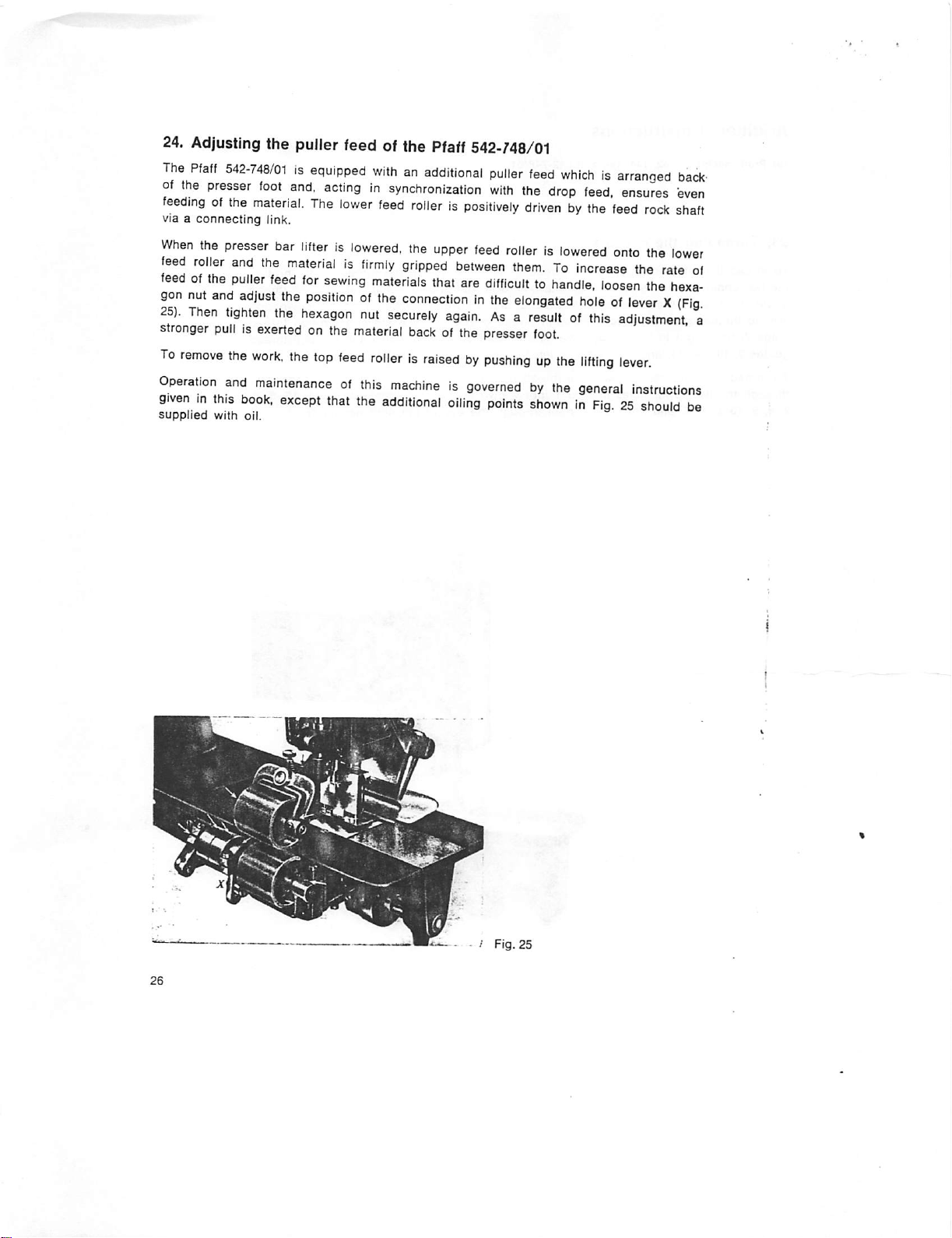
24.
Adjusting the puller feed of the
The
Pfaff
542-748/01isequipped
of
the
presser
feedingofthe
via a
connecting
When
the
feed
roller
feedofthe
gon
nut
and
25).
Then
stronger
To
remove
foot
material.
link.
presser
tighten
pullisexerted
the
and
the
puller
adjust
work,
bar
materialisfirmly
feed
the
the
the
and,
actinginsynchronization
The
lower
lifterislowered,
for
sewing
positionofthe
hexagon
on the
top
feed
Pfaff
542-/48/01
withanadditional
feed
rollerispositively
the
upper
gripped
materials
that
connectioninthe
nut
securely
material
back
of the
puller
with
feed
rollerislowered
between
are
difficulttohandle,
again.Asa
presser
feed
the
drivenbythe
them.Toincrease
elongated
resultofthis
rollerisraisedbypushingupthe
whichisarranged
drop
feed,
feed
loosen
holeofleverX(Fig.
foot.
lifting
ensures
rock
onto
the
lower
the
rate
the
hexa
adjustment
lever.
bacif
even
shaft
of
a
Operation
giveninthis
supplied
with
and
maintenanceofthis
book,
except
oil.
that
machineisgovernedbythe
the
additional
oiling
points
general
instructions
shownInFig.25should
be
'
Fig.
25
Page 27
Additional
for
Pfaff
The
Pfaff
btop-motor
standard
an extra-large vertical rotary hook.
instructions
machines
543-712/01
543-712/02rsa
andaroller
motor
andadisc-type
and
single-needle
thread
543-712/02
tension,
thread
sewing
while
tension.
machine
the
Pfaff
Both
these
equipped
withatwo-speed
543-712/01isfitted
machines
are
equipped
with
with
a
,1
r
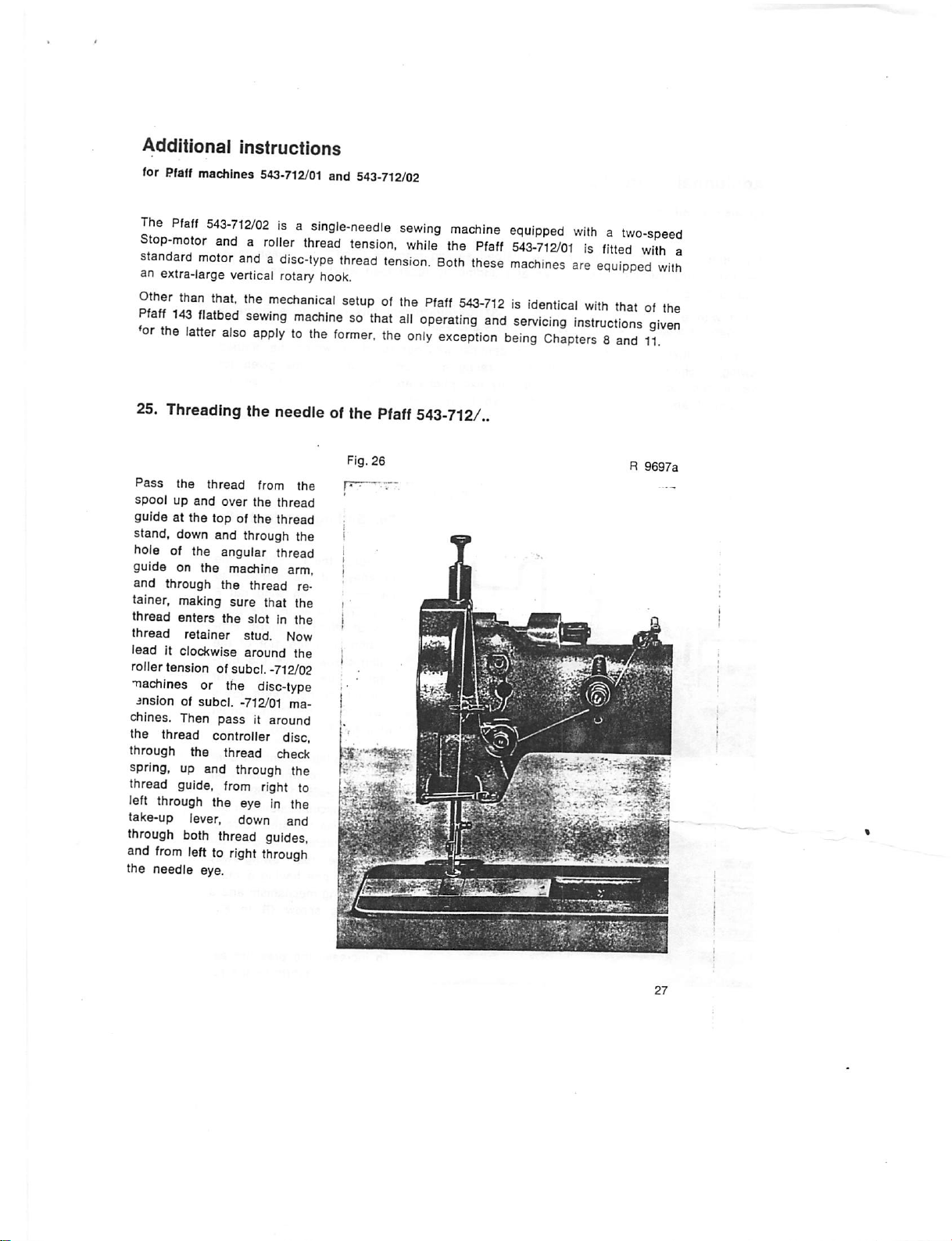
25.
Pass
spoolupand
guide
stand, down and through the
hole of the angular thread
guide on the machine arm,
and
tainer. making
thread
thread
lead it clockwise around the
roller tension of subcl.-712/02
machines or the disc-type
insionofsubcl.
chines. Then
the thread controller disc,
through the
spring, up and through the
thread guide, from right to
left through the eye in the
take-up lever, down
through both thread guides,
and
the needle eye.
the
flatbed
latter
sewmg
also
applytothe
machinesothat
Threading the needle ofthe
the
thread
at the top of the
through
enters
retainer
from
lefttoright
over
the
sure
the
slot
stud. Now
-712/01 ma
pass
thread
from the
the
thread
thread
thread
that the
in the
it around
check
and
through
T':
re
former,
Fig.
26
»he
all
the
Pfaff
Pfaff
543-712Isidentical
operating
only
exception
543-712/,
and
servicing
being
with
thatofthe
instructions
Chapters8and
R
given
11.
9697a
Page 28

Additional
for Pfaff machines 546-748/01
The
Pfaff
two
extra-iarge
feeding of "problem" materials.
Fitted
withasubcl.
intended for attaching waistbands to trousers and skirts.
Other
than
sewing
this
machine
the
foot
Instructions
546-748/01isa
vertical
rotary
-368/01,
that
the
Pfaff
machinesothat
applytothem
lift
and
adjusting
two-needle,
hooks
flatbed
and
additional
sewing
-369/01or-371/01
546-748/01isidentical
the
the
general
also.
puller
The
feed
operating
only
exceptions
which
R
attachment
with
and
are
given
9680
machine
puller
feed
our
standard
servicing
are
below.
26.
fitted
with
unison
which
ensures
this
machineisprimarily
two-needle,
instructions
the
instructions
Setting
the
feed,
smooth
flatbed
given
for
settin.
foot lift
for
To adapt the
thickness
be sewn,
(Fig. 27) and adjust the posi
tion of lifting
nection
lifting crank. Move
nection upward for a higher
foot lift, or downward for a
lower
wing nut F
If
delicate
tinuetopucker
a
subcl.
-371/01
foot
lift
ly, It Is recommended to re
place the rear swing-away
folder by one having a built-
in retaining mechanism and a
regulating screw (R in Fig.
28).
To
increase
ertedcrthe
f«
lift the
of
the
material
loosen
H in
foot
machine,
was
wing
eccentric
the
slotofthe
lift.
Then
securely.
fabrics
should
when
-368/01, -369/01 or
although
adjusted
the
pressure
fabricbythe
the
tighten
sewn
correct
nut
con
con
con
to
F
on
the
ex
re-
Page 29
taining
.backward;
For
terial,
and
the
St
tongue,
pressure,
easy
press
lever
to
lifting
latterInpositionbylever
(Fig. 27).
turn
to
decrease
turnitforwards.
removalofthe
against
raise
the
pressers
screw
the
ma*
the
knee
vibrating
and
lock
R
Fig.
28
27.
Adjusting
The Pfaff
behind the
the
546-748/01
presser
puller
feed
is equipped
with
an additional puller feed
which
is arranged
foot and, acting in synchronization with the unison feed,
ensures
even feeding of the material. The lower feed roller is positively driven by the feed rock
shaft
via a connection and
By lowering
presser
lower feed roller and both
of the puller feed so that It
needles,
tighten
adjust
the
the
hexagon
position of
has
a buiit-in retaining mechanism.
bar lifterSj(Fig. 27),
advance
the
exertsastronger
connection
nut securely.
the
upper
feed roller is lowered
material together. To increase the
pull on the material at the
Z (Fig. 27) in relation to
the
feed lever.
onto
the
rate
of feed
backofthe
Then
Page 30

Additional
for
Pfaff
Pfaff
machines
nical
setup,
both
machines
machines
exterior
instructions
4141
and
4141
and
design
are
equipped
ter-clockwise.inaddition,
needle
bar
crank.
Apart
from
the
needle
threading
chines
141
and
145
applytoPfaff
chines
are
chainstitch
sewing
4145
4145
closely
resemble
and
dimensions.
withaconstant-motion
they
are
fitted
withathread
instructions,
machines
machines,
bobbin
Cl.
141
and
Insteadofa
rotary
the
general
4141
and
winding
R
6312
145
machinesmtheir
vertical
nipper
instructions
4145
rotary
hook,
however,
looper
which
moves
whichisoperatedbythe
given
for
Pfaff
also.
(Since
the
latter
naturallyisomitted.)
28.
Threading
Pfaff
Pass
the
thread
up to the top thread guide of
the
thread
and through both holes in the
pin on the machine arm,
through the upper hole in the
thread
guide
arm (as shown in Fig. 29),
around
lower
clockwise
tween
right to left through the hole
in
the
sion,
guide and the thread guide
on
from left to right through the
needle
the
holeinthe
the
the
take-up
leverofthe
through
the
needle
eye.
of
4141
and
from
stand,
then
on the machine
pin.
through
thread
around
tension
discs,
lever, below
automatic
the lower
clamp,
mecha
coun
the
4145
the
spool
down
guide,
and
thread
ma
ma
tf\
be
from
ten
and
Page 31
Additional
for Pfaff machines fitted with thread pulier/trimmer •900/..
Since
these
puller/trimmer,
nated.
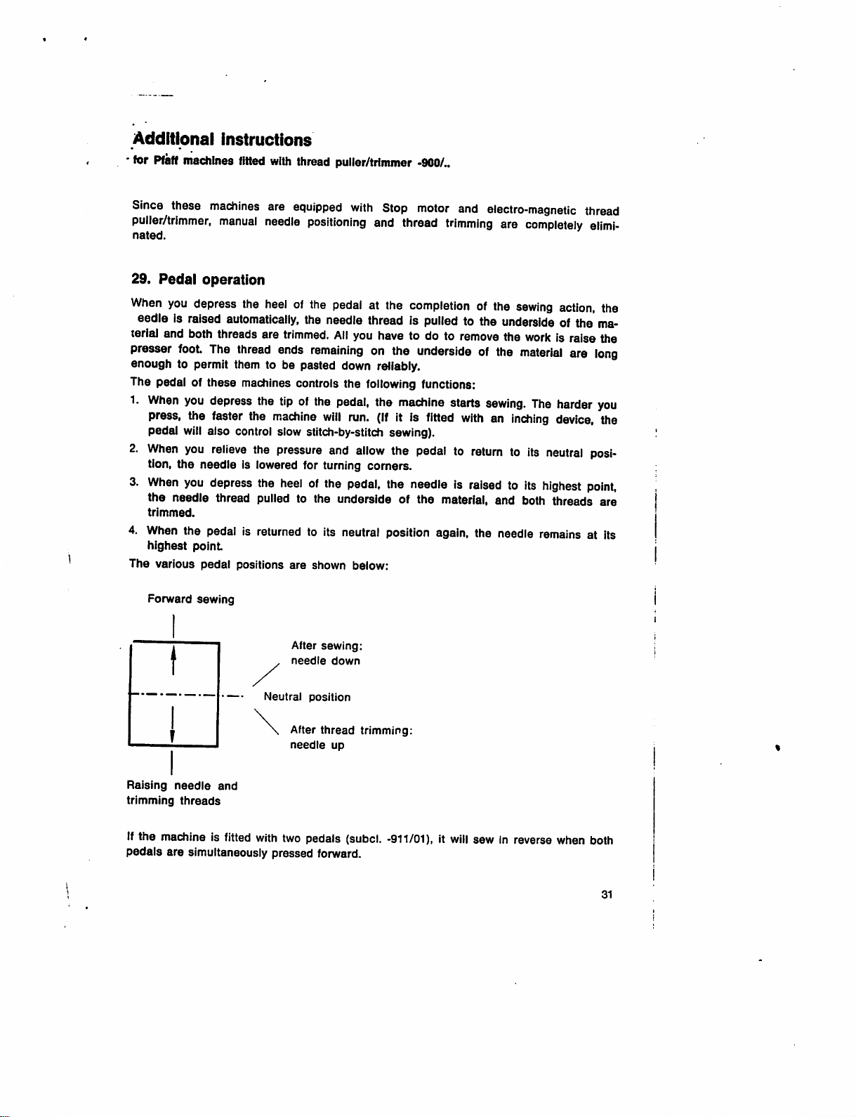
29.
Pedal
When
you
eedle is
teriaJ
and
presser
enough to permit them to be pasted down reliabiy.
The pedal of these machinescontrols the
1.
2.
3.
4. When the pedal is returned to its neutral position again, the needle
The
foot
When
press, the faster the
pedal
When
tion, the needle is lowered for turning comers.
When
the needle thread
trimmed.
highest
various
Instructions
machines
manual
operation
depress
raised
both
threads
The
you
depress
will
also control slow stitch-by-stitch sewing).
you
relieve
you
depress
point
pedal
are
equipped
needle
the
heelofthe
automatically,
are
trimmed.
thread
ends
the
tipofthe
machine
the
pressure
the
heelofthe
pulled
positions
are
with
positioning
the
needle
remaining
will
and
pedal
All
pedal,
run.
and
at the
thread is
you
on the
following
the
allow
pedal,
to the underside of the material, and both threads are
shown
below:
Stop
motor
and
thread
trimming
completionofthe
pulled
have
to do to
undersideofthe
functions:
(If
the
the
machine
it is
starts
fitted
pedaltoreturntoits
needleisraisedtoits
electro-magnetic
are
sewing
to the
underside
remove
the
material
sewing.
withaninching
completely
action,
of the
work
is raisethe
are
The
harder
device,
neutral
highest
remains
thread
elimi
the
ma-
long
you
the
posi
point,
at its
Forward
Raising
trimming
Ifthe machine is fitted
pedals are simultaneously pressed forward.
sewing
needle
threads
and
After
needle
Neutral
with
position
After
needle
two pedals (subcl.
sewing:
down
thread
up
trimming:
-911/01),
it will
sewinreverse
when
both
31
Page 32

Guards
irra^Tn^are'Tegularly
rjlrgrorthTfingerguard
version.
vei
Please
make
sure
that
....
Take-up lever guard (Fig.31)
All
machines
safety
are
normally
regulations.Itis
fitted
this
guardisalways
equipped
imperative
withaguard
and
the
methodoffittingitdepend
fitted
withatake-up
that
this
which
protects
correctly.
R
11466
Fig. 30
lever
safety
deviceisfittedatall
the
operator's
on
the
times.
firtgers
matdtine
Page 33

Belt
guardonbalance
This
guard
The
belt
guardismountedasfollows:
Guard 1 is
entrance
covers
secured
completely.
the
point
with two
wheel
R
11369
(Fig. 32)
where
screws
A
the
belt
runs
onto
2 and positioned so
the
balance
wheel.
that
it covers the point of belt
¥rv.--:-;iSws
Page 34

Belt guard below tabletop (Fig. 33)
This guard covers the belt below the tabletop.
Loosen
the
guard.
wing
nut 4, and
position
guard 5 so that
motor
puliey
R
10865
and
V-belt
run
freely
in
"
f'-vj
\
Page 35

• #
I
{
i •«
'
Troubfe
shooting
Machlrte
Cause
Wrong
Needle
Needle
Incorrect
^hread
i
Cause
For
Thread
Knotty
Needle
Thread snarled up.
Faulty stitch formation
Cause
Improper
"Wrong
Piecesofthread
or
under
Needle
Cause
Wrong
Needle
Needle
skips stitches
needle
bent
inserted
threading.
breaks
anyofthe
tensions
thread.
point
tension.
needle
bobbin
breaks
needle
bent
too
thin.
system.
incorrectly.
reasons
indicated
too tight
bluntordamaged.
size
and/or
thread
between
case
system.
tension
tension
above.
used.
discs
spring.
Remedy
For
correct
Insert
Orient
toward
8, 23, 25 and 28.
Remedy
See
remedies
Regulate
Use
high-quality
Replace
Check
to
needle.
Remedy"^
Regulate
See
Chapter
Remove
structed In Chapter 10.
Remedy
Insert
needleofcorrect
in Chapter 6.
Insert
new
Insert thicker
needle
new
needleasInstructedInChapter
needlesothat
the
sewing
listed
tensionsasInstructedInChapteria
thread
needle.
upper
threading
tensionsasinstructedInChapter
&
thread
and
.
needle.
needta
system
hook.
above.
its
see
short
Chapter
groove
In Chapters S.
only.
from
spoolofthread
re-adjust
tensionasIn
systemasInstructed
6.
7
faces'
ia
'Cause
• ^
^
thread.
Machine
Lackofoil.
Wrong
Hook
binds
lubricant
race
obstructedbypieces
'
of
.Remedy.'
Oil
machineasInstructedInChapters
and'21.
Use
machine-oil.
Trytofree
balance
should
structedInChapter
- •
only
non-reslnous
the
wheel
fall,
dismantle
jammed
back
and
ia
and
add-free
threadasyou
forth.Ifthis
the
sewing
sewfno
rock
action
hookasIn
3.-13
the
Page 36

M
« • 6
\} :
I-
1 *
f':'
Nr.
296-12-07
064/1275
rsaPTf
engl. P.
Printed In
West
C:
Germany
-•??.
♦
*1
vlT'
 Loading...