

PEUGEOT XS1P37QMA-2 Workshop Manual
Direction commerciale
Animation technique réseau
WORKSHOP MANUAL
-
50 CC ENGINE 4 STROKE
2 VALVES
SYM

Workshop manual
Technical network leadership
Reproduction or translat ion, even partial, is forbi dden without the written co nsent of Peugeot Motocyc les

TABLE OF CONTENTS
1
Reproduction ou traduction, même partielle, interdite sans autorisation écrite de Peugeot Motocycles
TABLE OF CONTENTS
TABLE OF CONTENTS . ... ....................................... ... ... ... .... ... ....................................... ... ... ... ... ....................... 1
PRODUCTS DANGER SYMBOLS USED..... ... .... .......................................... ... ... ... ... .... ................................... 3
CHARACTERISTICS......................................................................................................................................... 5
Capacities..................................................................................................................................................5
SPECIAL IMPORTANT POINTS....................................................................................................................... 6
Oil and fuel.................................................................................................................................................6
TIGHTENING TORQUES ................................. .... ... ... ... ... .......................................... .... ... ................................ 7
SPECIAL TOOLS .............................................................................................................................................. 8
Standard tools............................................................................................................................................9
OPERATION....................................................................................................................................................10
Putting the engine on the stand...............................................................................................................10
Changing the engine oil ...........................................................................................................................10
PRIMARY TRANSMISSION............................................................................................................................ 11
Removal of the primary transmission cover.............................................................................................11
Removal of the drive pulley......................................................................................................................11
Removal of the driven pulley....................................................................................................................12
Changing the drive pulley bearings..........................................................................................................12
Checking the drive belt ............................................................................................................................12
Removal of the clutch lining assembly.....................................................................................................13
Refitting the clutch lining assembly..........................................................................................................14
Removal of the starter system .................................................................................................................15
Fitting the starter system .........................................................................................................................16
SECONDARY TRANSMISSION...................................................................................................................... 17
Removal of the secondary transmission ..................................................................................................17
Replacing the bearings of the relay box...................................................................................................18
Crankcase.........................................................................................................................................................18
Relay box cover .............................................. .................................... ... ...........................................................18

TABLE OF CONTENTS
2
Reproduction ou traduction, même partielle, interdite sans autorisation écrite de Peugeot Motocycles
CARBURETTOR ............................................................................................................................................. 19
Removal of the carburettor.......................................................................................................................19
Removal of the choke ..............................................................................................................................19
Removal of the starter holder and its gasket ...........................................................................................19
Removal of the throttle valve....................................................................................................................20
Removal of the float, needle valve and jets..............................................................................................20
Removal of the mixture screw..................................................................................................................22
Removal of the pick-up pump ..................................................................................................................22
Removal of the pick-up pump suction valve.............................................................................................22
Removal of the deceleration enrichment device ......................................................................................23
Removal of the carburetor heater ............................................................................................................23
Removal of the intake pipe.......................................................................................................................24
MAGNETO FLYWHEEL/FREEWHEEL........................................................................................................... 25
To remove the magneto flywheel .............................................................................................................25
Removal of the overrunning clutch...........................................................................................................26
Checking the overrunning clutch..............................................................................................................27
CYLINDER HEAD/CYLINDER/PISTON.......................................................................................................... 29
Removal of the cylinder head...................................................................................................................29
Removal of the camshaft and/or rockers .................................................................................................31
Removal of the valves or valve stem seals ..............................................................................................32
Removal of the cylinder / piston...............................................................................................................34
Checking the cylinder...............................................................................................................................35
Checking the piston .................................................................................................................................35
Checking the piston rings.........................................................................................................................35
Installing the piston rings on the piston......................... ... ........................................................................35
Fitting the piston.......................................................................................................................................36
Fitting the cylinder....................................................................................................................................36
Setting the timing .....................................................................................................................................38
Checking the timing .................................................................................................................................39
Installing the valve clearance........................ ... ... .......................................... ... ... .... ... ..............................40
Checking the valve clearance..................................................................................................................40
CRANKCASE .................................................................................................................................................. 41
Removal of the crankshaft .......................................................................................................................41
Checking the crankshaft and conrod assembly .......................................................................................42
Fitting the conrod and crankshaft assembly.............................................................................................43

PRODUCTS DANGER SYMBOLS USED
3
Reproduction ou traduction, même partielle, interdite sans autorisation écrite de Peugeot Motocycles
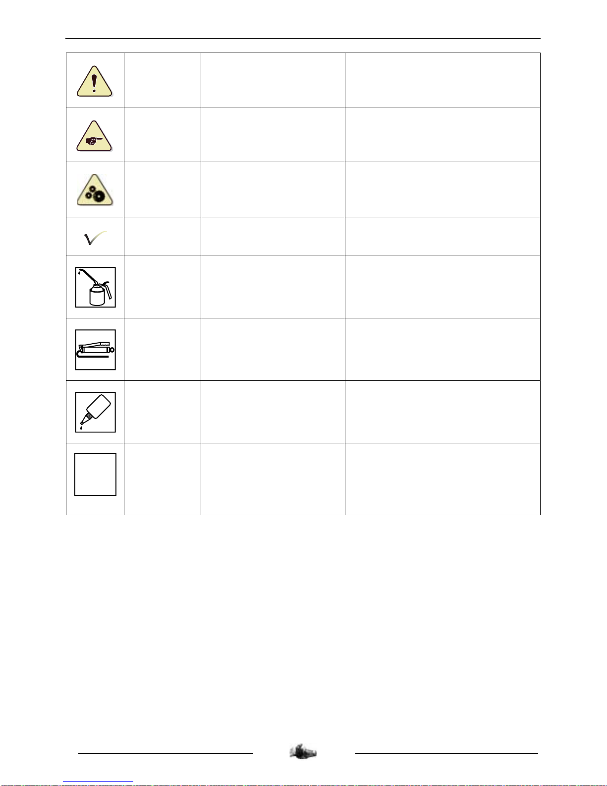
PRODUCTS DANGER SYMBOLS USED
Protection of individuals and of the environment.
Möbius band Recyclable.
Means that the product or the package
can be recycled. However, this does not
guarantee that the product will be
recycled.
Irritant
The product can irritate the
skin, eyes and repiratory
organs.
Avoid contact with skin and clothes. Wear
gloves, safety goggles and appropriate
clothes such as a cotton overall. Do not
breath fumes. If in contact, wash
thoroughly with water.
Flammable The product is flammable.
Keep it away from flames or any heat
source (barbecue, radiator, heater, etc.).
Do not leave the product in the sun.
Corrosive
The product can damage living
tissues or other surfaces.
Avoid contact with skin and clothes. Wear
gloves, safety goggles and appropriate
clothes such as a cotton overall. Do not
breath fumes.
Explosive
The product can explode under
certain circumstances (flame,
heat, impact, friction).
Avoid impacts, friction, sparks and heat.
Hazardous to
the environment
The product affects fauna and
flora. Do not dump it in
dustbins, sinks or in the
environment.
The ideal solution is to bring this product
to your nearest household waste recycling
centre.
Toxic
The product can seriously
affect health if it is inhaled,
ingested or in contact with skin.
Av oid direct contact with the body, even b y
inhalation. If you f ee l unwell, seek medical
advice immediately.
Do not throw
away into a
garbage can
One of the product's
component is toxic and can be
hazardous to environment. For
example: Used batteries.
This symbol informs the consumer that the
used product shall not be thrown awa y into
a garbage can, but shall be brought back
to the merchant or dropped at a specific
collection point.
Compulsory
gloves
Operation that can be
dangerous for people.
People's saf ety can be seriously aff ected if
the recommendations are not fully
respected.
PRODUCTS DANGER SYMBOLS USED
4
Reproduction ou traduction, même partielle, interdite sans autorisation écrite de Peugeot Motocycles
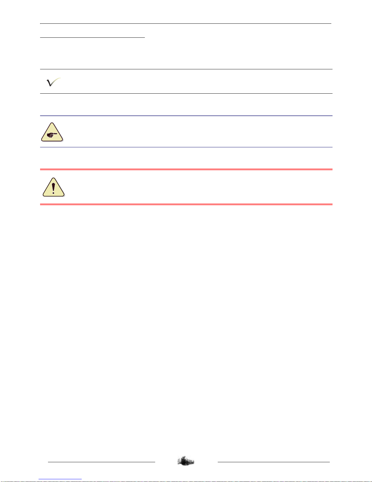
People's safety
Operation that can be
dangerous for people.
People's saf ety can be seriously aff ected if
the recommendations are not fully
respected.
Important
Operation that can be
hazardous to the vehicle
Indicate the specific procedures that shall
be followed in order not to damage the
vehicle.
Good operating
condition of the
vehicle
The operation must be carried
out in strict compliance with the
documents.
Serious damage to the vehicle and in
certain cases a cancellation of the
warranty can be involved if the
recommendations are not fully respected.
Note Operation that can be difficult.
Indicate a note which gives key
information to make the procedure easier.
Lubricate
Lubricate the parts to be
assembled.
Indicate the specific procedures that shall
be followed in order not to damage the
vehicle.
Grease
Grease the parts to be
assembled.
Indicate the specific procedures that shall
be followed in order not to damage the
vehicle.
Glue
Glue the parts to be
assembled.
Indicate the specific procedures that shall
be followed in order not to damage the
vehicle.
New part Use a new part.
Indicate the specific procedures that shall
be followed in order not to damage the
vehicle.
GLUE
N

CHARACTERISTICS
5
Reproduction ou traduction, même partielle, interdite sans autorisation écrite de Peugeot Motocycles
CHARACTERISTICS
Capacities
50 cc
Marking
XS1P37QMA-2
Type
4-stroke single-cylinder
2 valves per cylinder with chain driven overhead camshaft
Cooling By a circulation of forced air by means of a turbine on the flywheel magneto
Bore x stroke 37 x 46 mm
Cubic capacity 49.5 cc
Max. power output 2.8 kW at 8000 rpm
Max. torque rating 3.5 Nm at 6500 rpm
Lubrication Trochoid pump driven by a gear set from the crankshaft
Transmission By 2 variable pulleys and V-type belt
Clutch Centrifugal automatic
Exhaust Catalytic
Spark plug
NGK CR6HSA
Magneto flywheel 80 W
Fuel supply Carburettor Keihin NVC18 (c/d)
Standards Euro 3
Crankcase 0.7 l
Relay box 0.1 l
SPECIAL IMPORTANT POINTS
6
Reproduction ou traduction, même partielle, interdite sans autorisation écrite de Peugeot Motocycles
SPECIAL IMPORTANT POINTS
Oil and fuel
This engine is designed to run on 95 or 98 unleaded fuel only.
Never run the machine with a petrol/oil mixture.
Fuel pipes must absolutely be changed if there are any signs of wear, cracks, etc.
The clips are specific, they must always be changed each time they are removed and replaced
with new genuine parts clips.
Petrol is highly inflammable, do not smoke in the working area and avoid pr oximity to flames or
sparks.

TIGHTENING TORQUES
7
Reproduction ou traduction, même partielle, interdite sans autorisation écrite de Peugeot Motocycles
TIGHTENING TORQUES
Spark plug 12 Nm
Filler cap 20 Nm
Screen 15 Nm
Cylinder head
• Nut Ø 6 mm
• Screw Ø 6 mm
20 Nm
12 Nm
Camshaft gear cover 10 Nm
Camshaft gear 20 Nm
Valve clearance covers 15 Nm
Automatic tensioner 10 Nm
Automatic tensioner plug 8 Nm
Chain tensioner 10 Nm
Inlet manifold 10 Nm
Cylinder casings 12 Nm
RH casing cover 12 Nm
Freewheel 90 Nm
Oil pump 10 Nm
Transmission cover 10 Nm
Relay box cover 22 Nm
Relay box drain plug 10 Nm
Starter motor 10 Nm
Rotor 55 Nm
Turbine 10 Nm
Stator 10 Nm
Engine speed sensor 10 Nm
Drive pulley 55 Nm
Driven pulley 55 Nm
Clutch plate and shoes 55 Nm
SPECIAL TOOLS
8
Reproduction ou traduction, même partielle, interdite sans autorisation écrite de Peugeot Motocycles
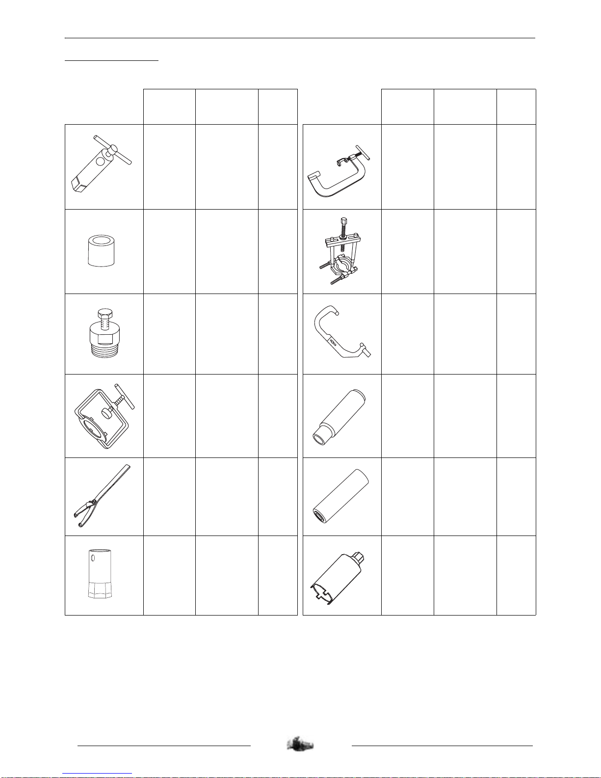
SPECIAL TOOLS
(*) New or modified tool
Tool N° Designation
Used
with
Tool N° Designation
Used
with
064765
Engine
mount
755982 754035 Valve lifter
068007
Protective
end-piece
small model
750806 755585
Bearing
extractor tool
750806
Flywheel
puller
68007 755982
Engine
mount
adapter
64765
752127
Clutch
compression
tool
752361 756668 Seal piston
752237
Adjustable
pin wrench
757990 Seal piston
752361
39 mm pipe
wrench
752127 800673
Freewheel
nut tool

SPECIAL TOOLS
9
Reproduction ou traduction, même partielle, interdite sans autorisation écrite de Peugeot Motocycles
Standard tools
Heat gun
Automatic resetting type
torque wrench
5 to 25 Nm
Type:Facom R.306A25
Intertia type extractor
tool for bearings from 6
to 18 mm
Type: Facom U.49PJ3
Automatic resetting type
torque wrench
10 to 50 Nm
Type: Facom J.208A50
Automatic resetting type
torque wrench
40 to 200 Nm
Type: Facom S.208A200
OPERATION
10
Reproduction ou traduction, même partielle, interdite sans autorisation écrite de Peugeot Motocycles
OPERATION
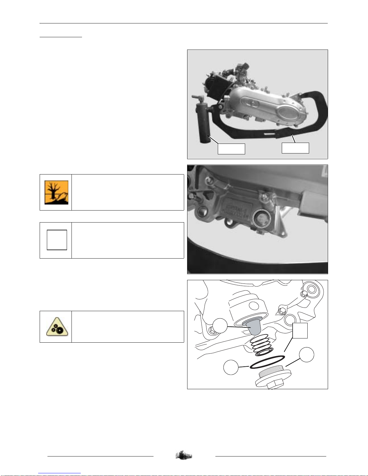
Putting the engine on the stand
- Fit the engine to adapter P/N 755982.
- Put the assembly on stand P/N 064765
clamped in the jaws of a vice.
Changing the engine oil
To drain the engine remove the cap and
let the oil drip.
Tightening torque: 20 Nm.
Replace the seal each time you change
the oil.
- Remove the strainer cap (1) and clean the
strainer (2).
Tightening torque: 15 Nm.
Every time oil is changed, the f ilter (2)
must be cleaned and the O-ring
changed (3).
755982
064765
N
1
2
3
N

PRIMARY TRANSMISSION
11
Reproduction ou traduction, même partielle, interdite sans autorisation écrite de Peugeot Motocycles
PRIMARY TRANSMISSION
Removal of the primary transmission
cover
- Remove the transmission cover (10 screw).
- Remove the paper gasket and the two 2
centering pins.
Tightening torque: 10 Nm.
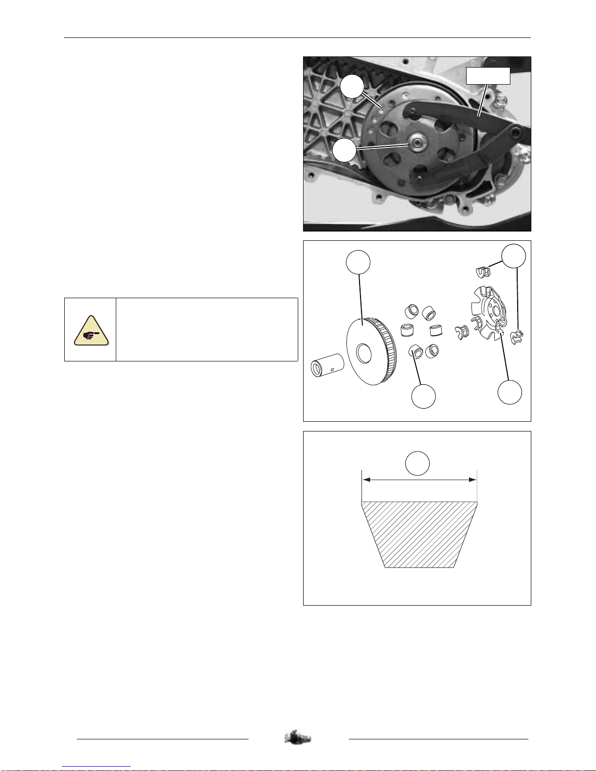
Removal of the drive pulley
- Hold the fixed flange with tool P/N 752237.
- Remove the nut (1) and washer (2) from the
fixed flange.
- Remove the fixed flange.
Tightening torque: 55 Nm.
- Remove the belt (3).
- Remove the plastic spacer (4).
- Remove the drive pulley (5) with the guide
hub (6).
752237
1
2
3
5
4
6
PRIMARY TRANSMISSION
12
Reproduction ou traduction, même partielle, interdite sans autorisation écrite de Peugeot Motocycles
Removal of the driven pulle y
- Lock the clutch drum (1) with the pin wrench
P/N 752237.
- Remove the nut (2).
- Remove the clutch drum and the clutch and
drive pulley assembly.
Tightening torque: 55 Nm.
Changing the drive pulley bearings
- Remove the ramp (1) and its 3 guides (2).
- Remove the moving flange (4)
6 bearings (3).
The bearings must be changed if they
show major signs of wear.
The guides shall be replaced if they
show signs of wear.
Checking the drive belt
- Measure the width of the belt (A).
Minimum width: 17.2 mm.
- Make sure the belt is not cracked.
1
2
752237
4
3
212
A
PRIMARY TRANSMISSION
13
Reproduction ou traduction, même partielle, interdite sans autorisation écrite de Peugeot Motocycles
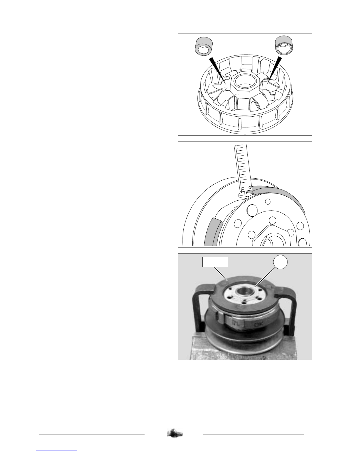
Reassembly:
- Proceed in reverse order to disassembly
and do not grease the bearings.
- When refitting, respect the way the rollers
are installed.
- Grease the moving flange bore lightly (high
temperature grease).
Removal of the clutch lining assembly
- Using the depth calliper, measure the
thickness of the clutch linings.
Mini. thickness: 2 mm.
- Compress the clutch drive pulley and driven
pulley assembly with the tool P/N 752127
clamped in the jaws of a vice.
- Remove nut (1) using spanner P/N 752361.
- Slacken tool P/N 752127.
1
752127
 Loading...