

Page 1
Handbook
Page 2
On-line handbook
Select one of the following means of access to view your
handbook on-line...
Find your handbook on the PEUGEOT website, under
"MyPEUGEOT".
This personal space offers advice and other useful information for
the care and maintenance of your vehicle.
Referring to the handbook on-line also gives you access to the latest information available, easily identified by the bookmark, associated with
this symbol:
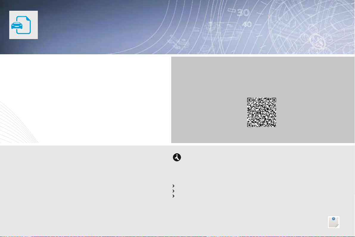
Scan this code for direct access to your handbook.
If the "MyPEUGEOT" function is not available on the PEUGEOT
public website for your country, you can find your handbook at the
following address:
http://public.servicebox.peugeot.com/ddb/
Select:
the language,
the vehicle, its body style,
the print edition of your handbook appropriate for the date of registration of
your vehicle.
Page 3
WELCOME
Your vehicle is fitted with only some of the equipment described
in this document, depending on its trim level, version and the
specification for the country in which it was sold.
We draw your attention to the following point:
The fitting of electrical equipment or accessories which are
not recommended by PEUGEOT may result in a failure of your
vehicle's electronic system. Contact a PEUGEOT dealer to be
shown the recommended equipment and accessories.
Key
Thank you for choosing an ION, a symbol of confidence, passion and
inspiration.
ION is the first 100% electric vehicle for PEUGEOT, 0% pollutant
emissions when driving and particularly quiet.
This handbook has been designed to enable you to make the most of
your ION in all circumstances.
Warning:
this symbol marks warnings which it is essential to observe for your
own safety, for the safety of others or to avoid any risk of damaging
your vehicle.
Protection of the environment:
this symbol accompanies advice relating to protection of the
environment.
Information:
this symbol draws your attention to additional information for better
use of your vehicle.
Page reference:
this symbol invites you to refer to the pages which provide details of
the function.
Page 4
Contents
Overview
Eco-driving
Monitoring
Instrument panel 9
Indicator and warning lamps 10
Main battery state of charge indicator 18
Energy consumption / generation indicator 19
Distance recorder 20
Trip distance recorder 20
Lighting dimmer 21
Service indicator 21
Range indicator 23
.
.
Access
Remote control key 24
Doors 27
Boot 28
Electric windows 29
Charging aps 30
Comfort
Front seats 31
Rear seats 33
Mirrors 35
Interior ttings 37
Ventilation 40
Heating 42
Air conditioning 42
Front demist - defrost 45
Rear screen demist - defrost 45
Driving
Driving recommendations 46
Starting - stopping the vehicle 47
Parking brake 48
Drive selector 49
Visibility
Lighting controls 51
Automatic illumination of headlamps 53
Headlamp adjustment 53
Wiper control 54
Courtesy lamp 55
Page 5

Contents
Safety
Direction indicators 56
Automatic operation of brake lamps 56
Hazard warning lamps 56
Horn 57
Emergency or assistance call 57
Under-ination detection 58
Braking assistance systems 62
Trajectory control systems 64
Front seat belts 65
Airbags 68
Child safety
Child seats 72
Deactivating the passenger's front airbag 75
ISOFIX child seats 81
Child lock 84
Practical info rmat ion
Charging the main battery 85
Ancillaries battery 93
Temporary puncture repair kit 97
Changing a wheel 101
Snow chains 105
Changing a bulb 106
Changing a fuse 114
Changing a wiper blade 119
Towing the vehicle 119
Precautions for washing 120
Accessories 120
Checks
Bonnet 123
Front compartment 124
Rear compartment 125
Checking levels 126
Checks 128
Technical data
Motor and main battery 129
Weights 130
Dimensions 131
Identication markings 132
Audio equipment and telematics
Emergency or assistance 133
Audio system / Bluetooth 135
Visual search
.
Alphabetical index
.
Page 6
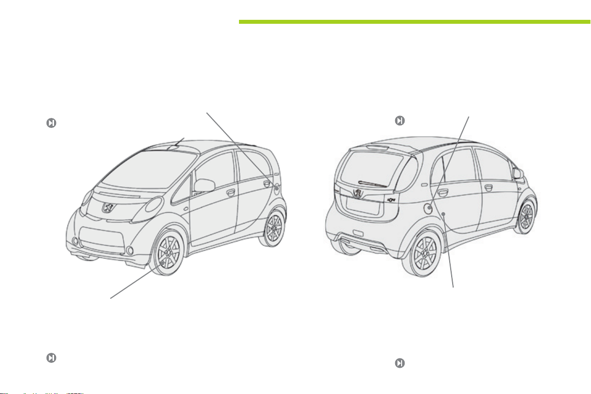
Overview
Exterior
Fast charging ap
Available according to equipment, this flap
should be used to recharge your vehicle from a
special fast charging station.
91
ASR and ESP systems
These are associated systems that assure the
directional stability of the vehicle, within the
limits of the laws of physics.
64
4
Normal charging ap
This flap should be used to recharge your
vehicle from a domestic power point.
85
Temporary puncture repair kit
This kit is a complete system consisting of a
compressor and a sealant cartridge, to allow
the temporary repair of a tyre.
97
Page 7
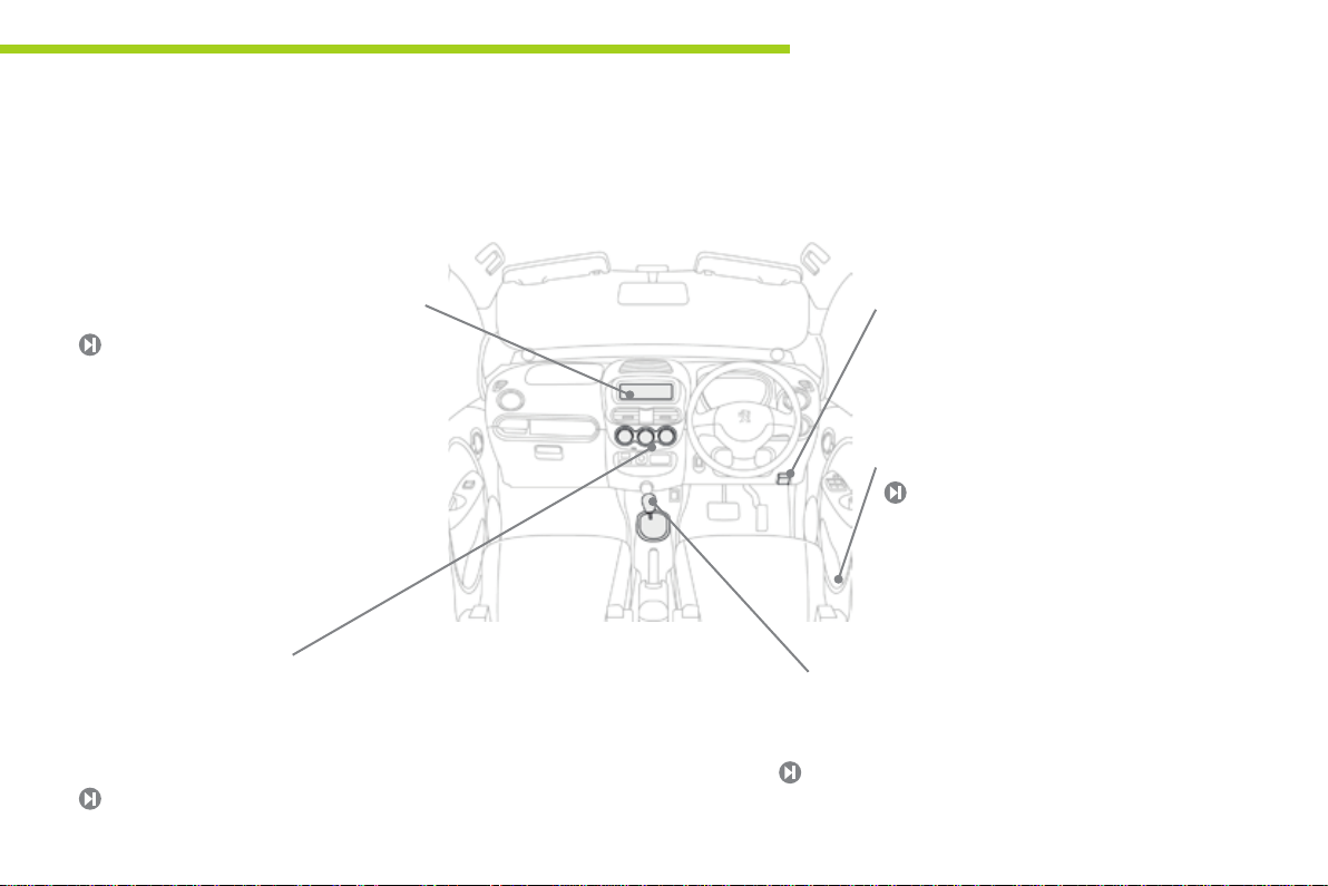
Interior
Overview
.
Audio system
This system benefits from the latest
technology: MP3 compatible audio system,
USB player, Bluetooth hands-free system, ...
135
Air conditioning
After setting the desired level of comfort,
the system controls this level according to
the exterior climatic conditions.
42
Charging ap interior opening
controls
Normal charging flap.
Fast charging flap (according to equipment).
30
Drive selector
Four-position drive selector: P, R, N and D.
49
5
Page 8
Overview
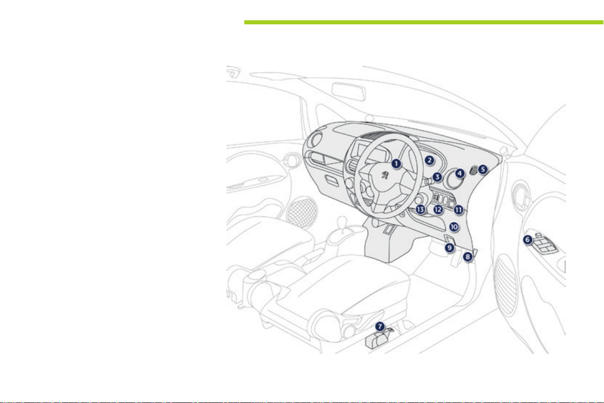
Instruments and controls
1. Driver's airbag.
Horn.
2. Instrument panel.
3. Wiper stalk.
4. Side vents.
5. Window demisting vent.
6. Electric window switches and switch
for deactivating the the front and rear
passenger electric window controls.
7. Opening control for the fast charging flap
(vehicle left hand side).
8. Bonnet release lever.
9. Opening control for the normal charging
flap (vehicle right hand side).
10. Fusebox.
11. Door mirror controls.
12. Headlamp height adjustment.
ASR/ESP deactivation switch.
13. Steering lock and ignition switch.
6
Page 9
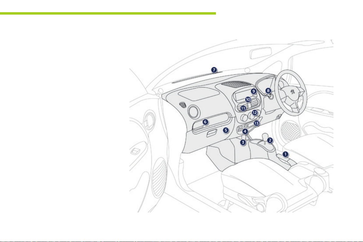
Instruments and controls
1. Parking brake.
2. Drive selector.
3. 12 V accessory socket.
4. Passenger's airbag deactivation.
USB port.
5. Glove box.
6. Cup holder.
7. Windscreen demisting vents.
8. Lighting and direction indicator stalk.
9. Audio system.
10. Hazard warning lamps switch.
11. Centre vents.
12. Heating / air conditioning controls.
13. Emergency or assistance call.
.Overview
7
Page 10

Eco-driving
For more economical driving, and increased range
Practical advice for everyday use to optimise the range of your vehicle by conserving battery power.
Adopt a smooth driving
style
The electrical consumption of your vehicle
depends greatly on your journey, your driving
style and your speed.
In all cases, adopt a smooth driving style.
Stay in the "Eco" zone indicated in the energy
consumption / generation meter: depress
the accelerator pedal progressively, without
sudden movement, and if the conditions permit,
drive at steady and moderate speed.
8
Recover energy
Anticipating the driving conditions allows you to
recover energy and increase the range of your
vehicle.
Use the "Charge" zone of the energy
consumption / generation meter whenever
possible: anticipate the traffic slowing
down and if the the conditions permit, use
deceleration rather than the brakes.
Control the use of your
electrical equipment
The heating and air conditioning systems
operate on energy from the main battery.
Excessive use of these systems greatly
reduces the range of your vehicle. Remember
to switch them off once the desired level of
comfort is reached and check their settings
every time you set off.
Control also the use of demisting / defrosting
and the heated seat.
Limit the causes of excess
consumption
As with any vehicle, limit the loads carried
in the vehicle and reduce wind resistance
(windows open above 30 mph (50 km/h), roof
bars, roof box, …).
Observe the recommendations
on maintenance
Check the tyre pressures regularly and
follow the schedule for routine servicing
recommended by PEUGEOT.
Page 11
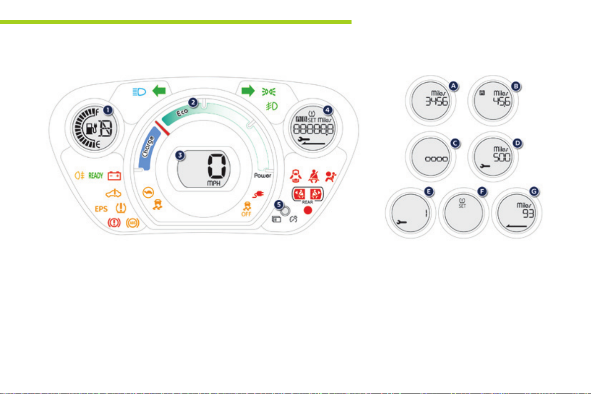
Monitoring
Instrument panel
Panel bringing together the various gauges and indicators for the operation of the vehicle.
Gauges and indicators
1. State of charge indicator for the main
battery.
Drive selector position indicator.
2. Energy consumption / generation
indicator.
3. Speedometer.
4. Screen.
5. Screen control button.
Display the various functions in turn.
Reset the function selected (trip recorder
or service indicator).
Adjust the level of instrument lighting.
For more information, refer to the
corresponding section.
1
Screen
A. Total distance recorder.
B. Trip distance recorder (Trip A or B).
C. Instrument panel lighting dimmer.
D. Distance remaining to the next service.
E. Time remaining to the next service.
F. Under-inflation detection.
G. Remaining range.
9
Page 12
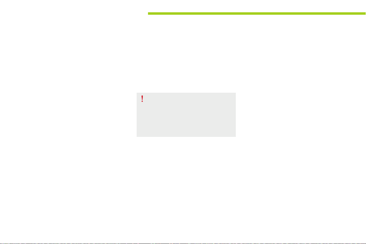
Monitoring
Indicator and warning lamps
Visual indicators informing the driver that
a system is in operation, is deactivated or has
a fault.
When the ignition is switched on
Certain warning lamps come on for a few
seconds when the vehicle's ignition is
switched on.
These same warning lamps go off after a few
seconds.
If you notice one of these warning lamps
remaining on, refer to the information on the
warning lamp in question.
Associated warnings
The illumination of certain warning lamps may
be accompanied by an audible signal.
The warning lamps may come on continuously
(fixed) or flash.
Certain warning lamps may come on in
one of two modes. Only by relating the
type of lighting to the operating status
of the vehicle can it be ascertained
whether the situation is normal or
whether a fault has occurred.
10
Page 13
Monitoring
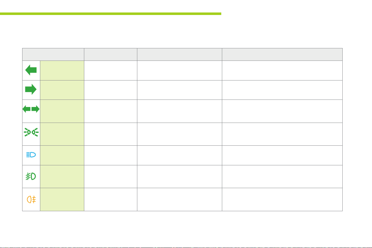
Operation indicator lamps
If one of the following indicator lamps comes on in the instrument panel, this confirms that the corresponding system has come into operation.
Warning / indicator lamp State Cause Action / Observations
Left-hand
direction indicator
Right-hand
direction indicator
Hazard warning
lamps
Sidelamps and/
or dipped beam
headlamps
Main beam
headlamps
Front foglamps On fixed. The front foglamps are switched on. Turn the ring on the stalk rearwards twice to switch off
Rear foglamp On fixed. The rear foglamp is switched on. Turn the ring on the stalk rearwards to switch off the
Flashing with audible
signal.
Flashing with audible
signal.
Flashing with audible
signal.
On fixed. The sidelamps and/or dipped beam
On fixed. The lighting stalk is pulled towards
The lighting stalk is pushed down.
The lighting stalk is pushed up.
The hazard warning lamps switch,
located on the dashboard, has been
operated.
headlamps are on.
you.
The left-hand and right-hand direction indicators and
their associated indicator lamps flash simultaneously.
Pull the stalk to return to dipped beam headlamps.
the front foglamps.
rear foglamp.
1
11
Page 14
Monitoring
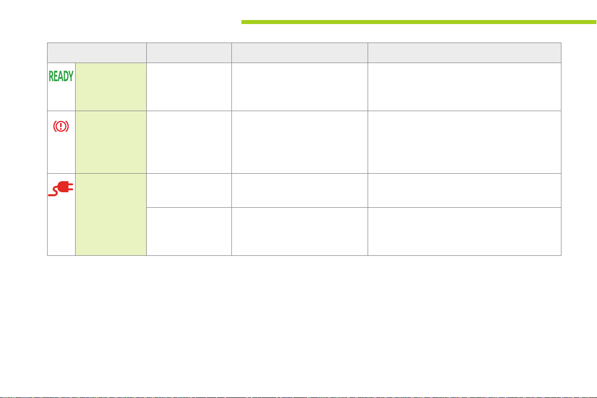
Warning / indicator lamp State Cause Action / Observations
Ready
(ready to move
off)
Parking brake On fixed. The parking brake is applied or not
Main battery
charge (normal
or fast)
On fixed,
accompanied by an
audible signal when it
comes on.
On fixed. The main battery is on charge. On completion of the charge, the lamp goes off.
Flashing. The charging cable is connected to
The vehicle is ready to move off and
you can press the accelerator.
properly released.
the vehicle but the main battery is not
yet charging.
The illumination period corresponds to the poweringup of the vehicle.
Release the parking brake to switch off the warning
lamp, keeping your foot on the brake pedal.
Observe the safety recommendations.
For further information on the parking brake, refer to
the "Driving" section.
Check the connection of the charging cable.
12
Page 15
Monitoring
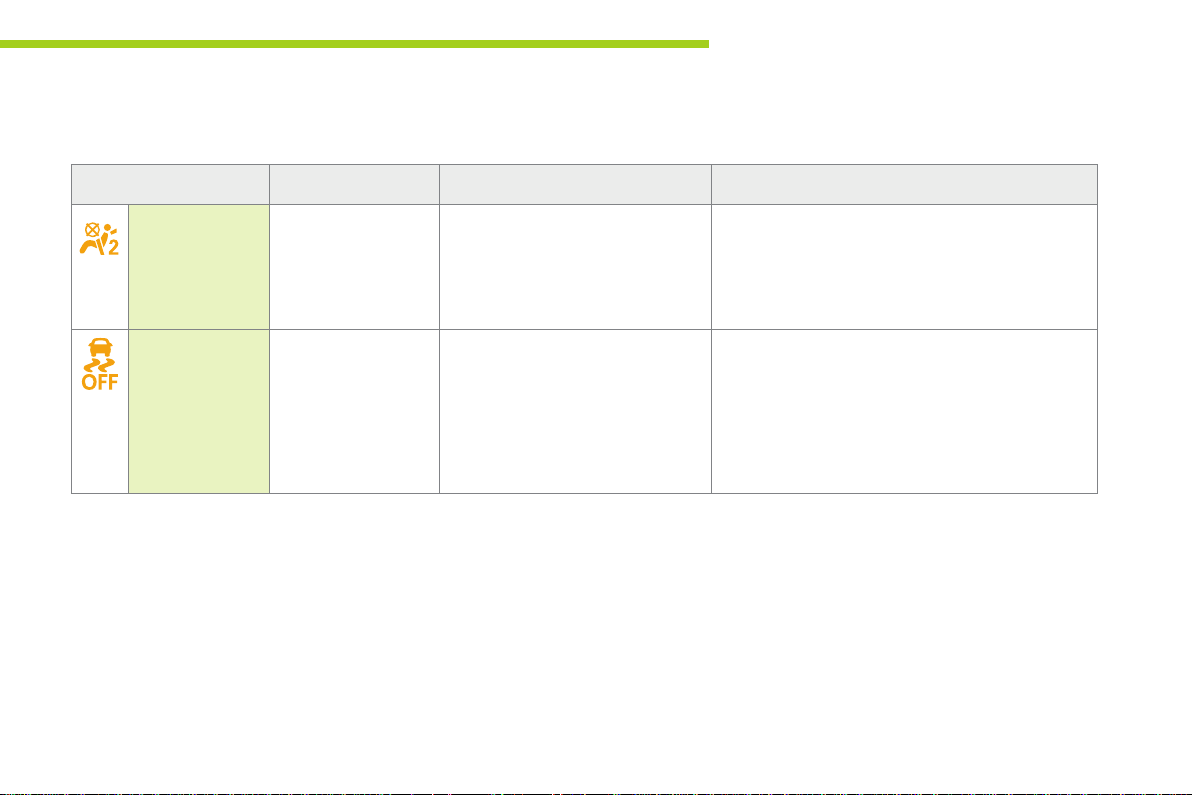
Deactivation indicator lamps
If one of the following indicator lamps comes on, this confirms that the corresponding system has been switched off intentionally.
This is may be accompanied by an audible signal.
Warning / indicator lamp State Cause Action / Observations
Passenger's
airbag system
ESP/ASR On fixed. The ESP/ASR off switch, located
On fixed, on the
centre console.
The control switch, located on the
centre console, is set to the OFF
position.
The passenger's front airbag is
deactivated.
in the dashboard (driver's side) is
activated.
The ESP/ASR is deactivated.
ESP: electronic stability programme.
ASR: anti-slip regulation.
Set the control switch to the ON position to activate
the passenger's front airbag. In this case, do not fit a
child seat in the rearward facing position.
Remember to check the position of the control switch
before starting your vehicle.
Press the button to activate the ESP/ASR.
The ESP/ASR system is automatically activated on
starting the vehicle.
1
13
Page 16
Monitoring
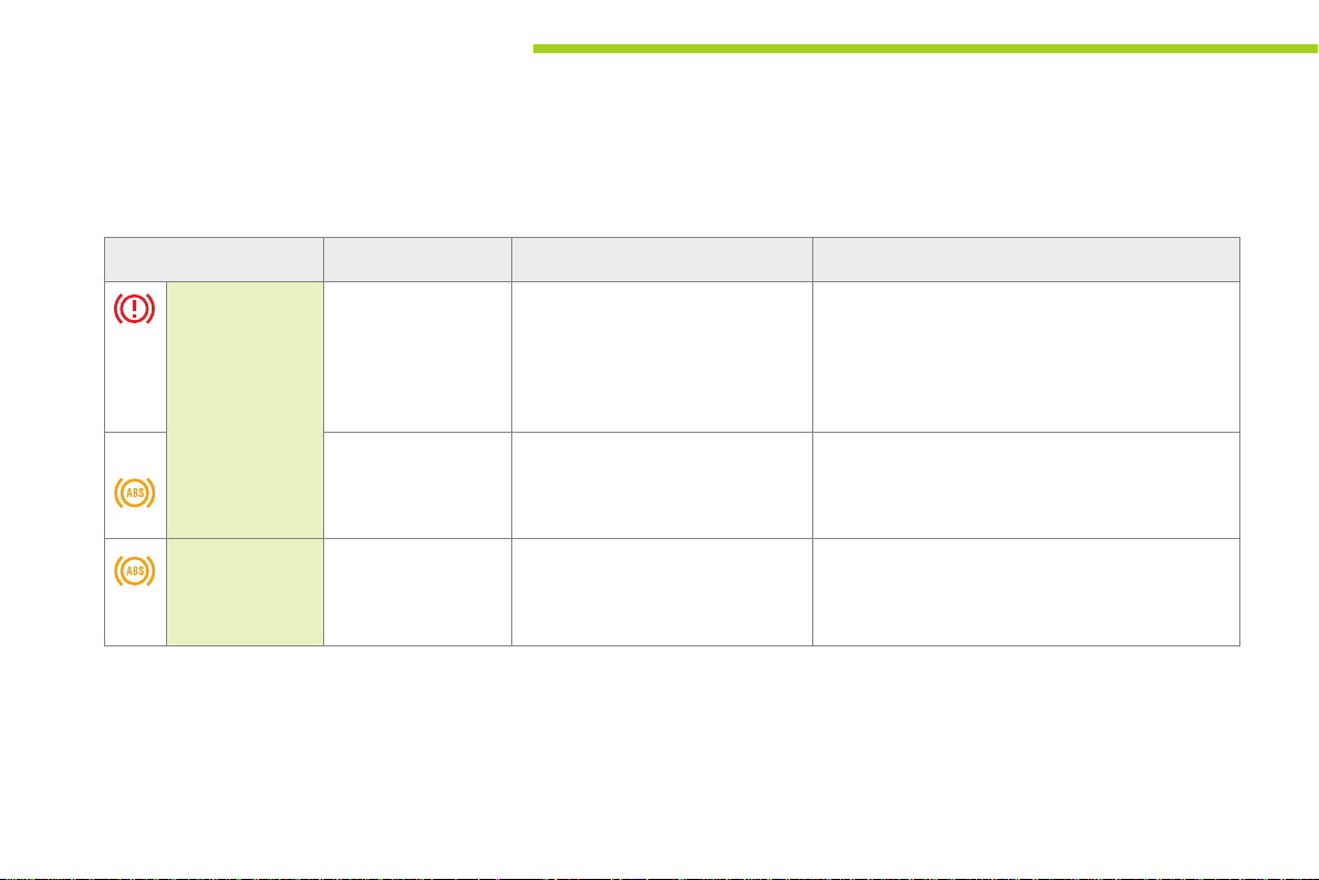
Warning lamps
When the engine is running or the vehicle is being driven, illumination of one of the following warning lamps indicates a fault which requires action on
the part of the driver.
Any fault resulting in the illumination of a warning lamp must be investigated further.
If you encounter any problems, do not hesitate to contact a PEUGEOT dealer or a qualified workshop.
Warning / indicator lamp State Cause Action / Observations
14
Braking On fixed. The braking system fluid level has
+ On fixed, associated
Anti-lock
Braking System
(ABS)
with the ABS warning
lamp.
On fixed. The anti-lock braking system has
dropped significantly.
or
Braking assistance system fault.
The electronic brake force distribution
(EBFD) system has a fault.
a fault.
You must stop as soon as it is safe to do so.
Top up with brake fluid listed by PEUGEOT.
If the problem persists, have the system checked by a
PEUGEOT dealer or qualified workshop.
You must stop as soon as it is safe to do so.
Have it checked by a PEUGEOT dealer or a qualified
workshop.
The vehicle retains conventional braking.
Drive carefully at reduced speed and contact a
PEUGEOT dealer or a qualified workshop without
delay.
Page 17

Monitoring
Warning / indicator lamp State Cause Action / Observations
Electronic
stability
programme
and anti-slip
regulation
(ESP/ASR)
+
Electric power
steering
Ancillaries
battery charge
Door(s) open On fixed,
Flashing. Activation of the ESP/ASR systems. The systems optimise traction and improve the
On fixed. Fault in the ESP/ASR systems. Have it checked by a PEUGEOT dealer or a qualified
On fixed. The electric power steering has a
fault.
On fixed. The ancillaries battery charging
circuit has a fault (dirty or loose
terminals, slack, transformer fault, ...).
A door or the boot is still open. Close the door or boot.
accompanied by an
audible signal.
directional stability of the vehicle.
Adapt your driving and moderate your speed.
workshop.
Drive carefully at reduced speed.
Have it checked by a PEUGEOT dealer or a qualified
workshop.
The warning lamp should go off when the motor is
started.
If it does not go off, contact a PEUGEOT dealer or
qualified workshop.
1
15
Page 18
Monitoring
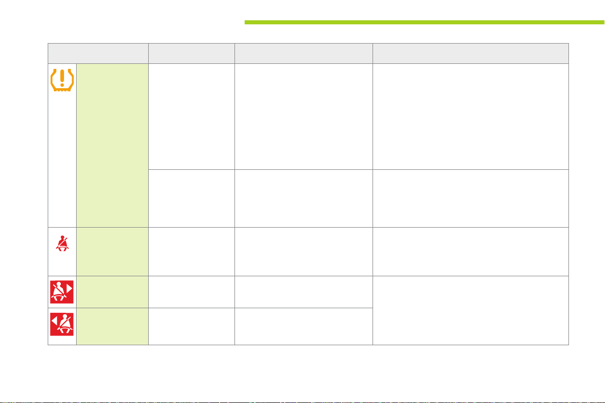
Warning / indicator lamp State Cause Action / Observations
Under-inflation fixed. The tyre pressure for one or more
wheels is too low.
Check the tyre pressures as soon as possible.
This check should preferably be done with the tyres
cold.
You must reinitialise the system after every adjustment
of one or more tyre pressures and after replacing one
or more wheels.
For more information refer to the "Under-inflation
detection" section.
16
Front seat belt
not fastened /
unfastened
Right hand rear seat
belt unfastened
Left hand
rear seat belt
unfastened
flashing then fixed. The system has a fault and/or one
On fixed, then
flashing, accompanied
by an audible signal.
On fixed. The right hand rear passenger has
On fixed. The left hand rear passenger has
or more wheels does not have a
detected sensor.
The driver and/or the front passenger
has not fastened or has unfastened
their seat belt.
unfastened their seat belt.
unfastened their seat belt.
The tyre pressures are no longer monitored.
Have the system checked by a PEUGEOT dealer or a
qualified workshop.
Pull the strap, then insert the tongue in the buckle.
Pull the strap then insert the tongue in the buckle.
Page 19
Monitoring
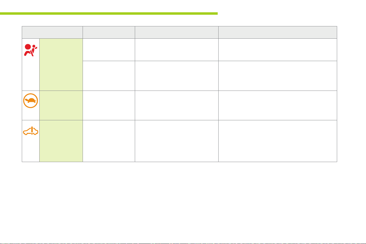
Warning / indicator lamp State Cause Action / Observations
Airbags On temporarily. When you switch on the ignition, this
On fixed. Fault with one of the airbag or seat
Protection
system for the
main battery
Self-diagnosis
system of the
main electrical
circuit
On fixed. The state of charge of the main
On fixed. Fault in the main electrical circuit. You must stop as soon as it is safe to do so.
warning lamp comes on for a few
seconds, then goes off.
belt pretensioner systems.
battery is too low or the temperature
of the main battery is too low...
If it does not go off, contact a PEUGEOT dealer or a
qualified workshop.
Have it checked by a PEUGEOT dealer or a qualified
workshop.
The power from the motor is limited.
Charge the main battery as soon as possible.
If the warning lamp does not go off, contact a
PEUGEOT dealer or qualified workshop.
Have it checked by a PEUGEOT dealer or a qualified
workshop.
1
17
Page 20
Monitoring
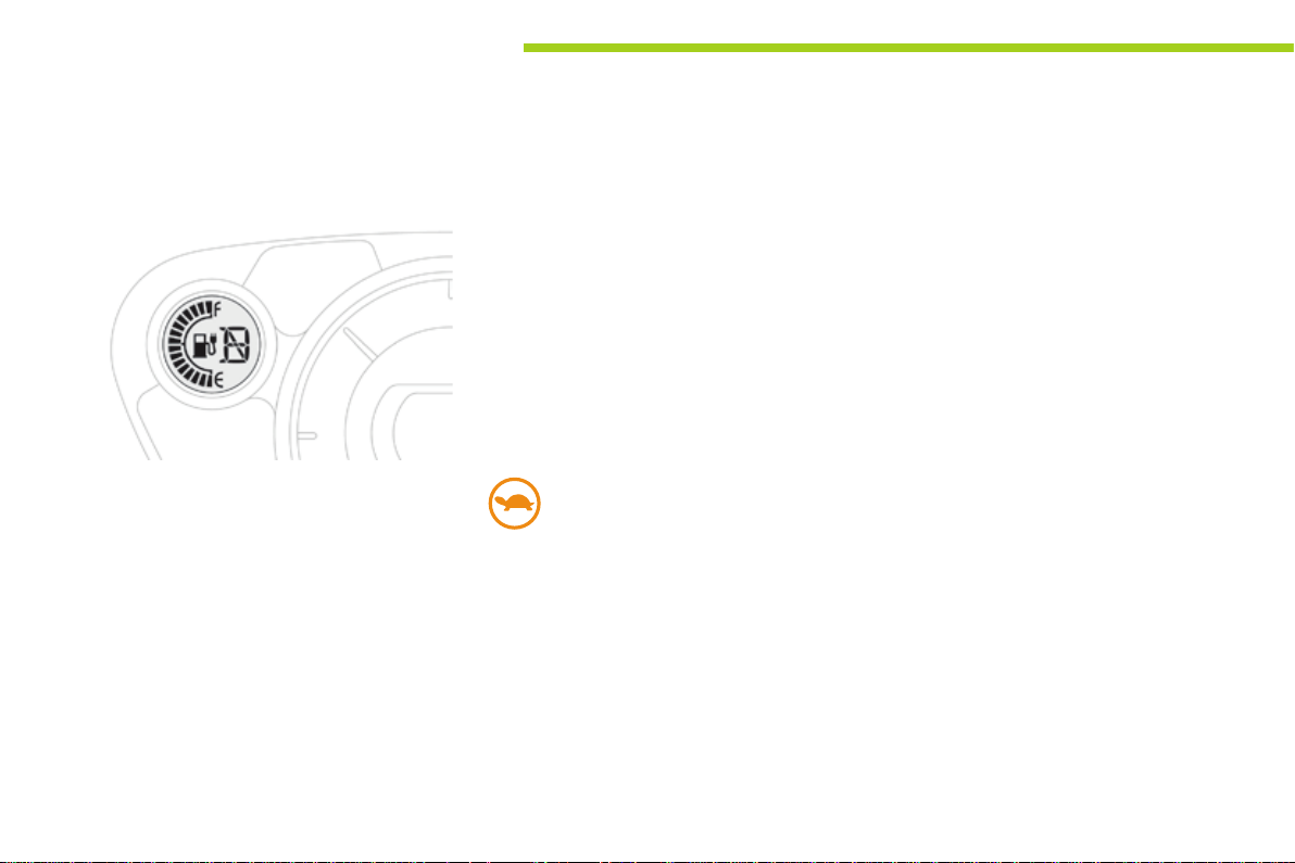
Main battery state of charge indicator
Display
The state of charge of the main battery is
displayed continuously in the instrument panel.
Low energy alerts
Four successive alerts indicate that the energy
available in the main battery is dropping to a
low level:
- 2 bars of the state of charge gauge in the
instrument panel, on and flashing: starting
to use the reserve.
- The last bar in the state of charge gauge
flashing.
- The last bar disappears: display of the
range disappears; the heating and air
conditioning are switched off.
- Display of this warning lamp in
the instrument panel: progressive
reduction in the power available
from the motor.
18
Page 21
Monitoring
Energy consumption / generation indicator
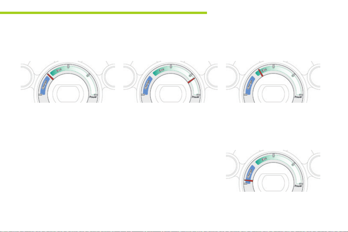
A system that informs the driver of the level of energy consumption or generation of the main battery.
"Neutral" position
On switching on the ignition, your vehicle
neither consumes nor generates energy in its
electric traction system: the needle is in the
"neutral" position (provided that the heating and
air conditioning are off).
Energy consumption
The needle moves to the right in proportion to
the energy consumption by the vehicle.
1
"E c o" z one
The needle is in this zone when the vehicle is
used so as to moderate electric consumption
and optimise its range.
"Charge" zone
The needle moves to the left in proportion to
the level of charge sent to the main battery,
during period of deceleration and braking.
19
Page 22
Monitoring
Instrument panel screen
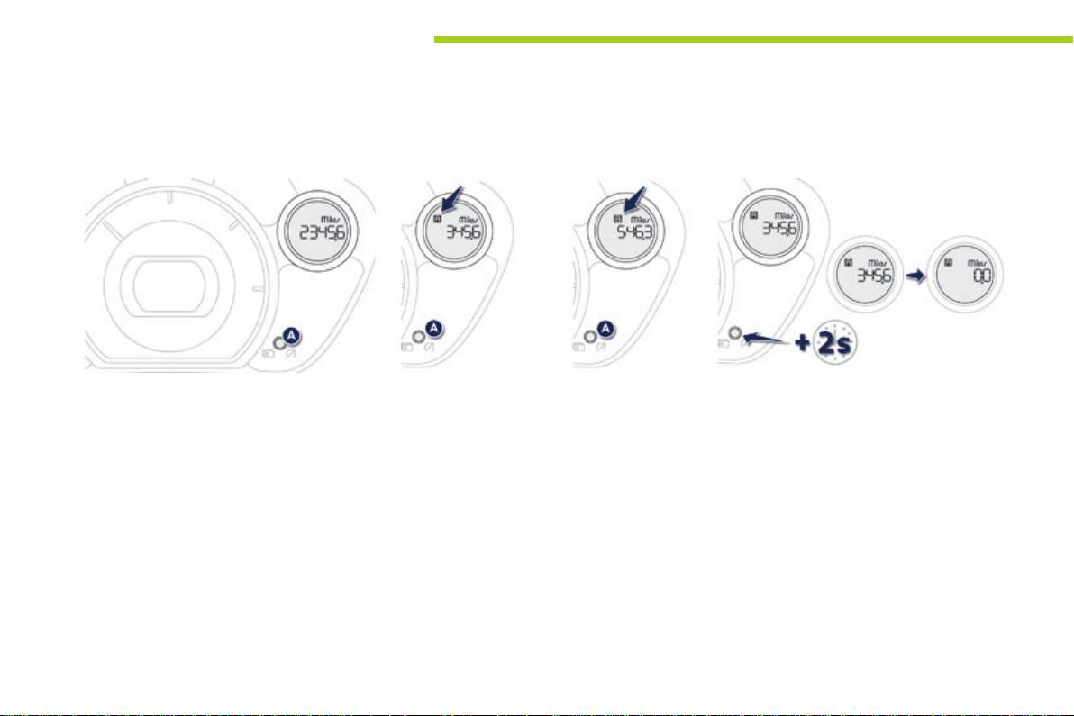
When the ignition switch is in the "ON" position, press button A repeatedly to display the following information in turn.
Distance recorder
System for measuring the total distance
travelled by the vehicle during its life.
Press button A.
The total distance appears in the screen.
Changing the speedometer units
With the total distance recorder displayed,
press and hold button A for a few seconds to
change the speedometer units (mph or km/h).
The range indicator is displayed in the units
(miles or km) corresponding to those of the
speedometer (mph or km/h).
Trip distance recorder (Trip A or B)
Each of these trip recorders indicates the
distance travelled since the last reset.
Press button A to display the desired trip.
Reset to zero
With the ignition on and either trip A or B
displayed, press the button for more than
2 seconds.
20
Page 23
Monitoring
1
Lighting dimmer
System for manual adjustment of the
brightness of the instruments and controls in
relation to the exterior brightness.
With the lighting on or off, press button A to
select the function, then hold down to change
the intensity of the lighting of the instruments
and controls in "day" or "night" mode.
The intensity of the lighting increases each time
button A is pressed.
When the lighting reaches the maximum
setting, press again to change to the minimum
setting.
When the lighting reaches the required
intensity, release button A.
The setting is saved when you release button A
and retained when the ignition switch is turned
to OFF.
Service indicator
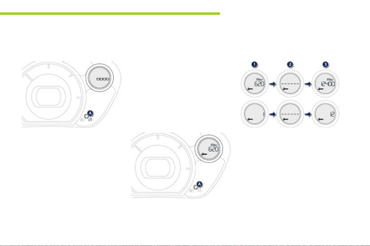
System which informs the driver when the
next service is due in accordance with the
manufacturer's servicing schedule.
The point at which the next service is due is
calculated from the last service indicator zero
reset.
This point can be indicated in one of two ways:
- the miles (km) remaining,
- the time remaining to the next service.
When the ignition is switched on, press
button A several times in succession until the
service indicator is displayed in the desired
units.
Operation
1. The screen indicates that 620 miles
(1000 km) or 1 month remain before the
next service.
2. The screen indicates that the date for the
service has been exceeded.
Every time the ignition is switched on,
the service spanner is displayed for a
few seconds to remind you that a service
should be carried out as soon as possible.
3. Once the service has been carried out, the
distance or the number of months to the
next service is displayed again.
21
Page 24
Monitoring
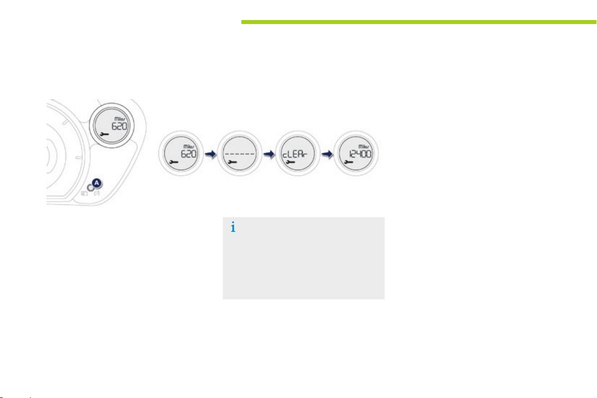
Resetting the service indicator to zero
22
After each service, the service indicator should
be rest to zero.
The procedures is as follows:
F Switch off the ignition (switch in the LOCK
or ACC position).
F Press the reset button A several times in
succession until the service indicator is
displayed.
F Press and hold the reset button for a few
seconds until the spanner flashes.
F Press the reset button while the spanner
is flashing to change the display from "---"
to "CLEAR".
The distance (or time) remaining before the
next service is due is displayed.
The display of "---", indicating that the
service date has arrived, comes on
automatically after a certain time and
distance travelled. The screen then
indicates the time remaining before the
next service is due.
Page 25

Monitoring
1
Under-inflation detect ion
You have to reinitialise the under-inflation
detection system after adjusting one or more
tyre pressures or after changing one or more
wheels.
Carry out the following procedure to do this.
F Press button A to select the system.
F Press and hold button A for at least
3 seconds.
There is an audible signal and the underinflation warning lamp flashes slowly until the
initialisation is complete.
Selecting the set of wheels and
tyres tted
If you have previous registered a second set
of wheels and tyres with sensor, you have to
select the corresponding set in the instrument
panel screen after fitting them.
Carry out the following procedure to do this.
F Press button A to select the system.
F Press and hold button A for more than
10 seconds, to change from set of tyres
and wheels 1 to set 2 or the other way
round.
Range indicator
This function gives an estimate of the number
of miles (km) that your vehicle can still cover,
based on the recent conditions of use (driving
style, use of heating, air conditioning...).
When the remaining range falls to a
low level, "- - -" is displayed in the
instrument panel.
The range can be displayed in miles or
kilometres.
To change the units, refer to the
"Distance recorder" section.
23
Page 26

Access
Remote control key
System used for centralised locking or unlocking of the vehicle using the door lock barrel or from a distance. It is also used to start the vehicle, as well
as providing protection against theft.
Unfolding / Folding the key
F First press button A to unfold or fold the key.
Unlocking the vehicle
Unlocking using the remote
control
F Press the open padlock to unlock
the vehicle.
Unlocking is confirmed by the interior lighting
which comes on for approximately 15 seconds
and the direction indicators which flash twice.
Depending on version, the door mirrors unfold
at the same time.
Unlocking using the key
F Turn the key to the right in the driver's
door lock to unlock the vehicle.
Locking is confirmed by the interior lighting,
which comes on for about 15 seconds and the
direction indicators, which flash twice.
On the other hand, the door mirrors are not
unfolded (see the "door mirrors" section).
The passenger's door lock barrel does
not lock or unlock the other doors or
the boot.
Locking the vehicle
Normal locking using the remote
control
F Press the closed padlock to lock
the vehicle.
Locking is confirmed by the direction indicators
which come on once.
Depending on version, the door mirrors fold at
the same time.
Normal locking using the key
F Turn the key to the left in the driver's door
lock to lock the vehicle.
Locking is confirmed by the direction indicators,
which flash once.
On the other hand, the door mirrors are not
folded (see the "door mirrors" section).
The vehicle will lock itself again
automatically after thirty seconds
unless a door or the boot is opened.
This function avoids inadvertent
unlocking.
24
Page 27

Access
Anti-thef t p rotection
Electronic immobiliser
The key contains an electronic chip which has
a special code. When the ignition is switched
on, this code must be recognised to permit
starting.
This electronic immobiliser locks the control
system a few moments after the ignition is
switched off and prevents starting by anyone
who does not have the key.
In the event of a malfunction and if your vehicle
does not start, contact a PEUGEOT dealer as
soon as possible.
Remote control problem
In the event of a remote control malfunction,
you can neither unlock nor lock your vehicle.
F First of all, use the key in the driver's door
lock to unlock or lock your vehicle.
F Then, contact a PEUGEOT dealer to check
the operation of the remote control and
replace the battery if necessary.
2
25
Page 28

Access
Lost keys
Visit a PEUGEOT dealer with the vehicle's V5 registration document and your personal
identification documents.
The PEUGEOT dealer will be able to retrieve the key code and the transponder code
required to order a replacement key.
Remote control
The high frequency remote control is a sensitive system; do not operate it while it is in your
pocket as there is a possibility that it may unlock the vehicle, without you being aware of it.
Do not repeatedly press the buttons of your remote control out of range and out of sight of
your vehicle. You run the risk of stopping it from working.
The remote control does not operate when the key is in the ignition, even when the ignition
is switched off.
Locking the vehicle
Driving with the doors locked may make access to the passenger compartment by the
emergency services more difficult in an emergency.
As a safety precaution (with children on board), remove the key from the ignition when you
leave the vehicle, even for a short time.
Anti-thef t p rotection
Do not make any modifications to the electronic immobiliser system; this could cause
malfunctions.
26
When purchasing a second-hand vehicle
Have the key codes memorised by a PEUGEOT dealer, to ensure that the keys in your
possession are the only ones which can start the vehicle.
Page 29
Doors
Opening
Access
Locking/ unlocking from
the insid e
2
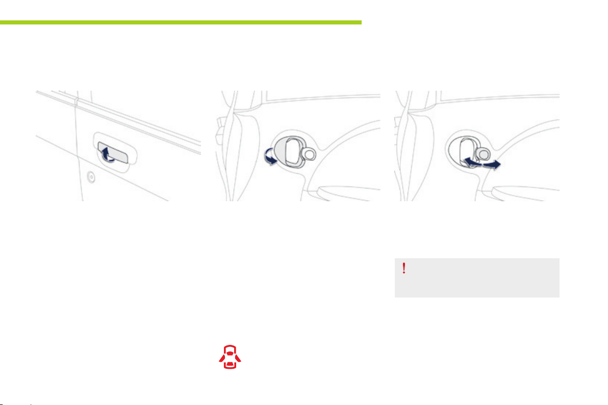
From outside
F After unlocking the vehicle using the
remote control or the key, pull the door
handle.
From inside
F Pull the front or rear door control to open
the door.
If the doors are locked:
- opening the driver's door unlocks the other
doors,
- the front passenger or rear doors must
then be unlocked manually using the front
locking control before they can be opened.
Closing
If a door or the boot is not closed
correctly, this warning lamp comes on
in the instrument panel until the door
in question or the boot is closed.
F Press the button on the driver's door
towards the front to lock and towards the
rear to unlock the vehicle completely.
The buttons on the front and rear
passenger doors only lock / unlock
the door in question.
27
Page 30
Access
Boot
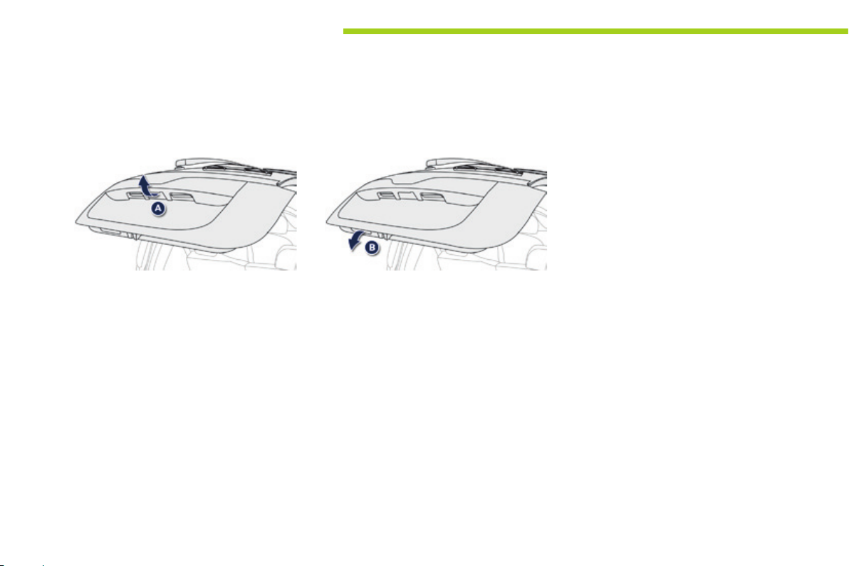
Opening
Closing
28
F After unlocking the vehicle using the
remote control or the key, press the
handle A and open the tailgate.
F Pull the handle B downwards to guide the
tailgate down,
F release the handle and press the exterior
surface of the tailgate gently to close it.
Page 31
Electric windows
System which opens or closes a window manually or automatically. It is fitted with a deactivation system to prevent misuse of the rear controls.
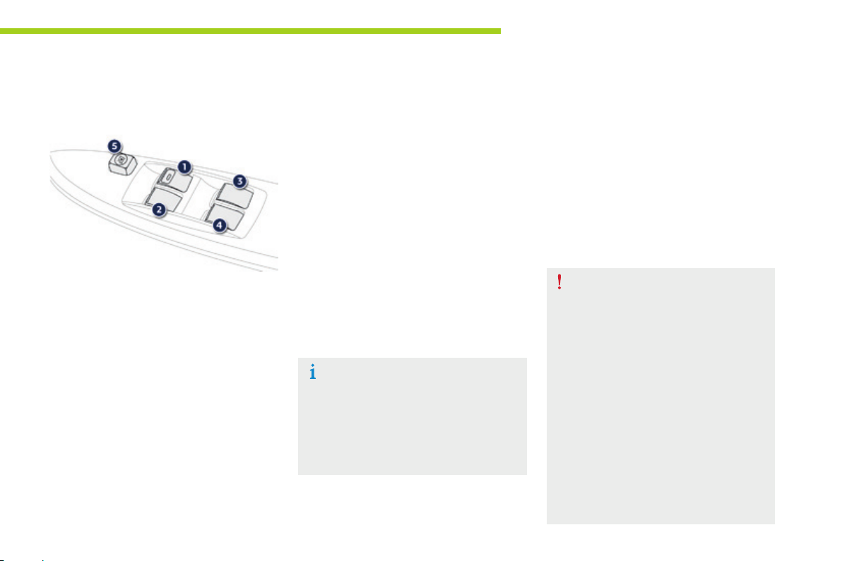
Access
1. Driver's electric window.
2. Passenger's electric window.
3. Rear right electric window.
4. Rear left electric window.
5. Deactivating the passenger and rear
electric window switches.
Operation
With the ignition on:
F Press the switch gently to open or pull it
gently to close. The window stops as soon
as the switch is released.
Automatic one-touch mode (driver's side)
F Press the switch fully to open. The driver's
window opens completely when the switch
is released.
F Pressing the switch again stops the
movement of the window.
The electric window switches remain
operational for approximately
30 seconds after the ignition is switched
off.
The windows can no longer be opened
or closed after the driver's door is
closed.
Deactivating the passenger and
rear electric window switches
F
For the safety of your children, press switch 5
to prevent operation of the passenger and rear
electric windows irrespective of their position.
When the button is pressed down, the switches are
deactivated.
When the button is raised, the switches are activated .
Always remove the key from the ignition
when leaving the vehicle, even for a
short time.
In the event of contact during operation
of the windows, you must reverse the
movement of the window. To do this,
press the switch concerned.
When the driver operates the
passenger electric window switches,
they must ensure that no one
is preventing correct closing of
the windows.
The driver must ensure that passengers
use the electric windows correctly.
Be aware of children when operating
the windows.
2
29
Page 32
Access
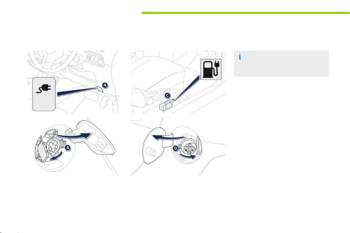
Charging aps
Normal charging
F Pull control A locate at the bottom of the
dashboard, driver's side, to release the
charging flap,
F Open the flap on the right of the vehicle,
F Press latch B to open the socket cover.
Fast charging*
For more information on charging
procedures, refer to the "Practical
information" section.
F Pull control C located alongside the driver's
seat, outer side, to release the flap,
F Open the flap on the left of the vehicle,
F Press latch D to open the socket cover.
30
* Depending on equipment.
Page 33
Front seats
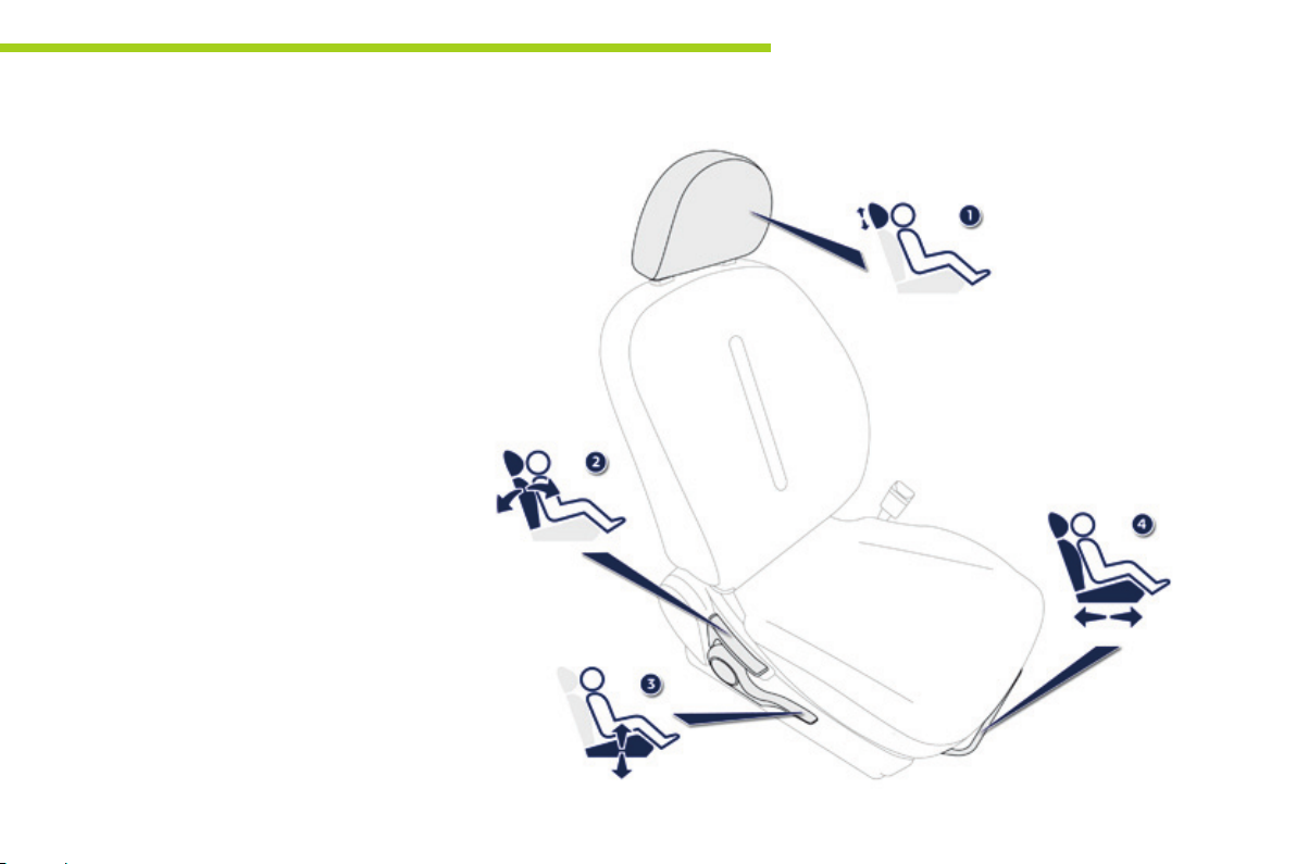
Manual adjustments
1. Adjustable head restraint
2. Adjustment of the backrest angle
Operate the control lever and adjust the
position of the backrest to the front or to
the rear.
3. Adjustment of the driver's seat height
Raise or lower the control lever the number
of times required to obtain the desired
position.
4. Forwards-backwards adjustment of the
seat position
Lift the control bar and slide the seat
forwards or backwards.
Comfort
3
31
Page 34
Comfort
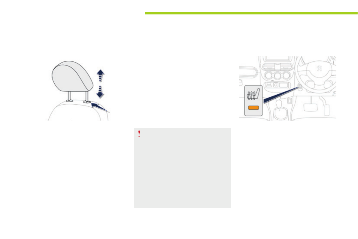
Heated seat control
32
Head restraint height adjustment
F To raise it, pull upwards.
F To lower it, push it downwards, pressing
the height adjustment button at the same
time.
F To remove it, raise it to the high position,
then remove it pressing the height
adjustment button at the same time.
F To refit it, engage the rods of the head
restraint in the apertures, pressing the
height adjustment button at the same time.
Never drive with the removed head
restraints in the vehicle as they could
be thrown around the vehicle on sharp
braking. They must always be in place
and adjusted correctly.
After installing the head restraint, check
that the height adjustment button has
engaged correctly.
The adjustment is correct when the top
of the head restraint is aligned with the
top of the head of the seated person.
Press the control switch, located on the
dashboard, to switch on the driver's seat
heating.
The warning lamp in the switch comes on.
The temperature is controlled automatically.
Pressing a second time stops operation.
Page 35
Rear seats
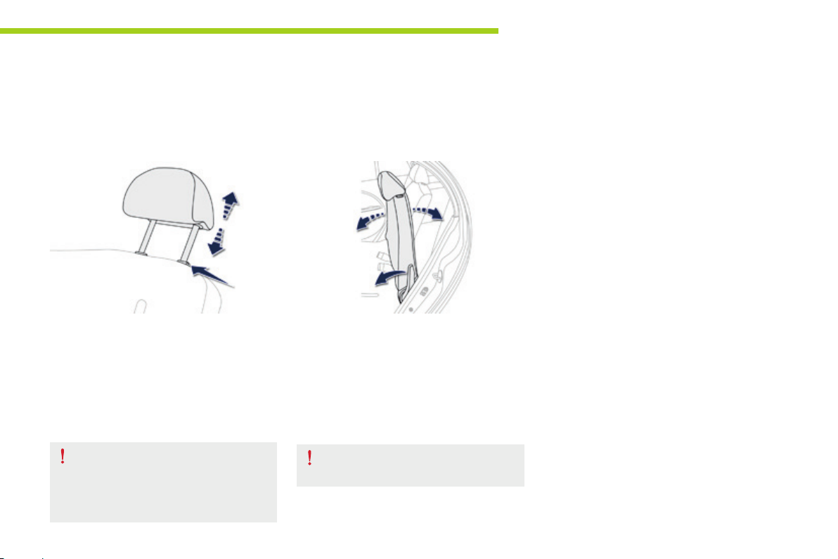
Rear seat comprising two adjustable, foldable backrests and a fixed cushion.
Comfort
Rear head restraints
These have a high position (comfort and best
safety) and a low position (best rear vision for
the driver).
They can also be removed.
To remove a head restraint:
F pull the head restraint fully upwards,
F then, press the lug.
When carrying rear passengers, never
drive with their head restraints removed;
ensure that they are in place and in the
high position.
Adjusting the backrest
angle
3
To adjust the backrest:
F pull the control forwards to release
the backrest,
F adjust the backrest then release
the control.
The backrest can be adjusted to one of
seven positions.
Always ensure that the backrest has
engaged correctly.
33
Page 36
Comfort
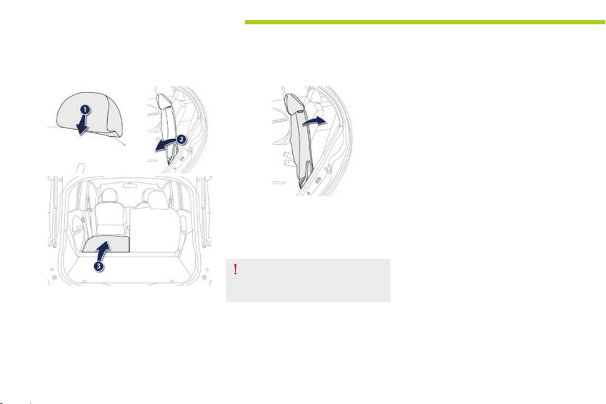
Folding the backrest
1. Place the head restraints in the low
position or remove them if necessary,
2. pull the control forwards to release
backrest,
3. fold the backrest forward.
Returning the seat backrest to its original position
F Push the seat backrest in position and
secure it,
F refit the head restraints or put them back
in place.
When returning the backrest to its
original position, take care not to trap
the seat belts.
34
Page 37
Mirrors
Door mirrors
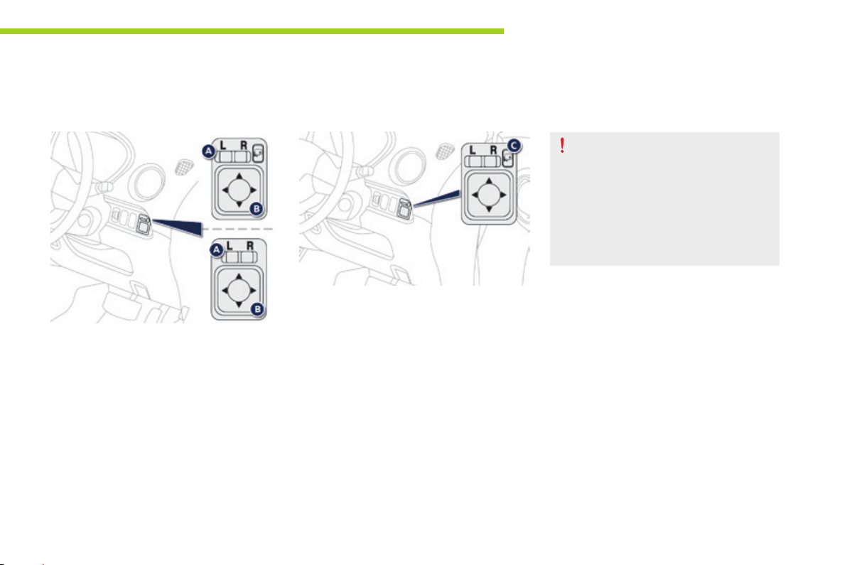
Adjustment
The mirrors can be adjusted when the ignition
switch is in the "ON" or "ACC" position.
F Move control A to the right or to the left to
select the corresponding mirror.
F Direct control B in all four directions to
adjust the mirror.
When adjustment is complete, return control A
to the central position.
Electric folding / unfolding*
F With the ignition switch in the "ON" or
"ACC" position: press control C to unfold
them.
F With the ignition switch in the "LOCK"
position: press control C within
30 seconds to fold them.
Comfort
The mirrors can also be folded
manually.
However, you must never unfold them
manually, otherwise the mirrors may
not remain in place correctly when
driving.
Always use control C to unfold them.
3
* Depending on version.
35
Page 38
Comfort
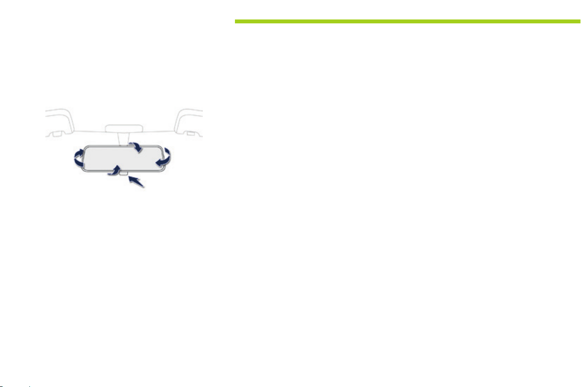
Rear view mir ror
Adjust the mirror by moving it up or down and/
or to the left or right.
The rear view mirror has two positions:
- day (normal),
- night (anti-dazzle).
To change from one to the other, push or pull
the lever on the lower edge of the mirror.
36
Page 39
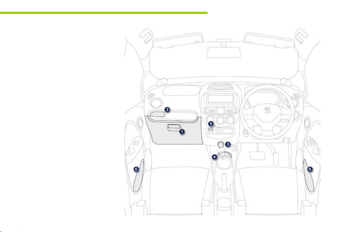
Interior ttings
1. Glove box
2. Retractable cup holder
Press the cover to open the cup holder
3. 12 V accessory socket (120 W)
Observe the maximum power rating to
avoid damaging your accessory
4. Open storage
5. PEUGEOT Connect USB
6. Door pocket
Comfort
3
37
Page 40
Comfort
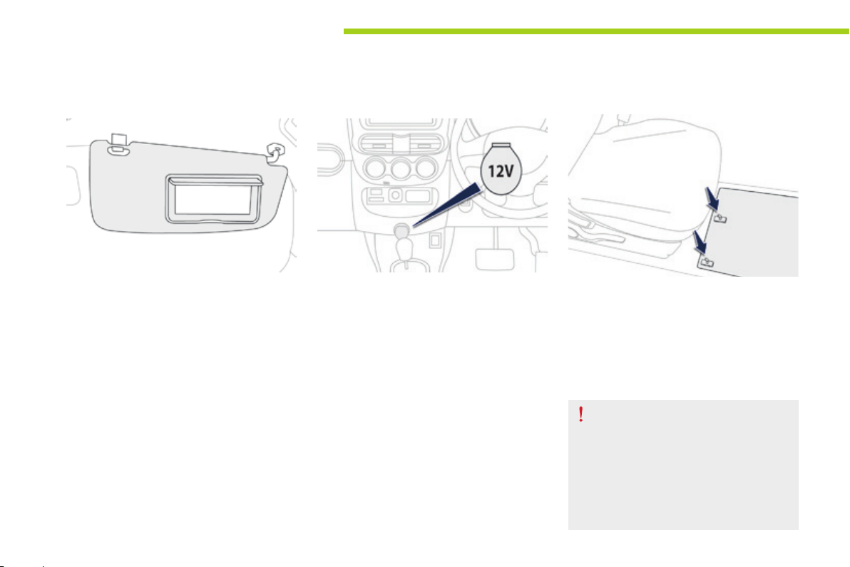
Sun visor
The sun visors fold forwards, and to the side
when they are unhooked.
They are fitted with a vanity mirror and a ticket
holder.
12 V accessory socket
F To connect a 12 V accessory
(max power: 120 W), lift the cover and
connect a suitable adaptor.
Mats
When removing the mat on the driver's side,
move back the seat as far as possible and
remove the fixings.
When refitting, position the mat correctly on the
pins and clip the fixings. Check that the mat is
secured firmly.
To prevent any risk of jamming under
the pedals:
- only use mats suited to the fixings
already present in the vehicle; it is
imperative that these fixings are
used.
- never fit one mat on top of another.
38
Page 41
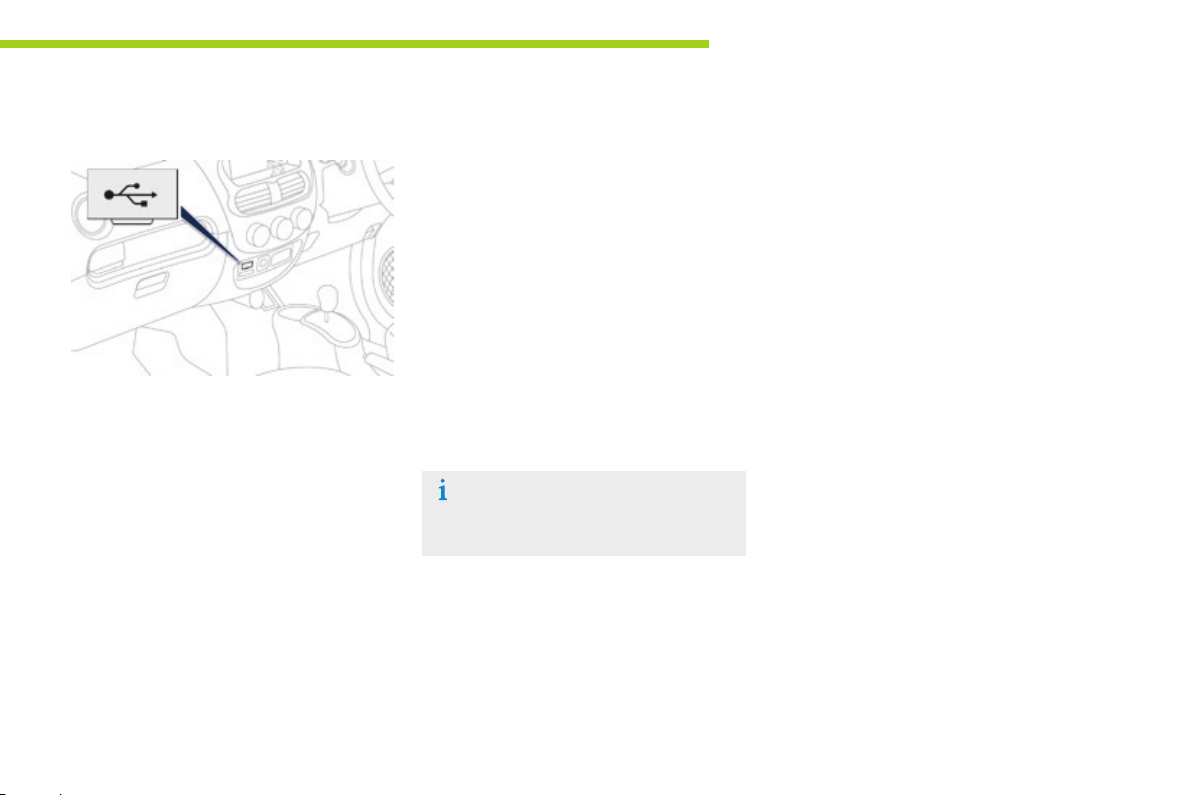
PEUGEOT C on n ec t US B
Comfort
3
This USB port, is located on the centre
console.
It permits the connection of portable devices,
such as a digital audio player of the iPod
or a USB memory stick.
It reads the audio files which are transmitted
to your audio equipment and played via the
vehicle's speakers.
You can manage these files using the audio
system controls.
®
type
When connected to the USB port, the portable
device charges automatically.
For more information on the use of
this system, refer to the "Audio and
Telematics" section.
39
Page 42
Comfort
Ventilation
System which creates and maintains good
conditions of comfort and visibility in the
vehicle's passenger compartment.
Air intake
The air circulating in the passenger compartment
is filtered and originates either from the outside via
the grille located at the base of the windscreen or
from the inside in air recirculation mode.
Controls
The incoming air follows various routes
depending on the controls selected.
The temperature control enables you to obtain
the level of comfort required by mixing the air of
the various circuits.
The air distribution control enables you to
select the air vents used in the passenger
compartment.
The air flow control enables you to increase or
reduce the speed of the ventilation fan.
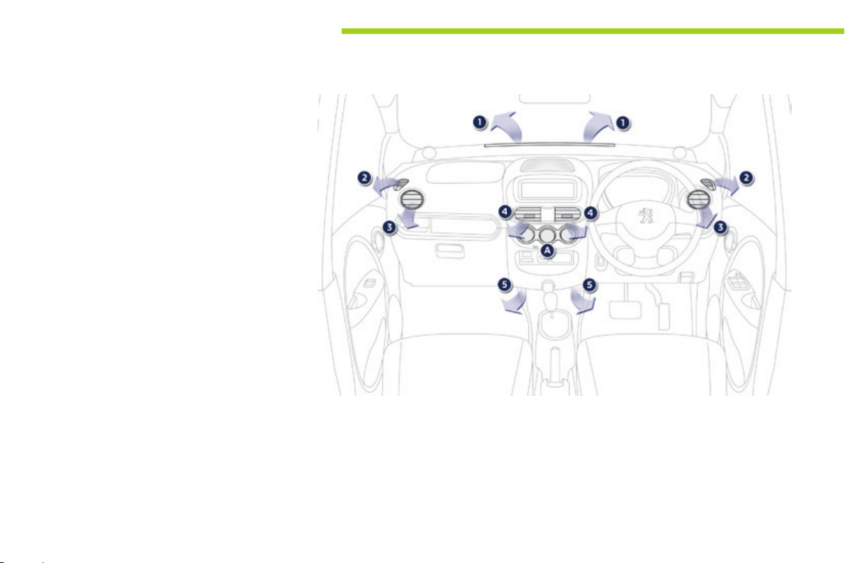
These controls are grouped together on control
panel A on the centre console.
Air distribution
1. Windscreen demisting/defrosting vents.
2. Front side window demisting/defrosting
vents.
3. Side adjustable air vents.
4. Central adjustable air vents.
5. Air outlets to the front footwells.
40
Page 43

Recommendations for ventilation and air conditioning
Comfort
In order for these systems to be fully effective, follow the operation and maintenance
guidelines below:
F If the interior temperature remains very high after the vehicle has been parked in the
sun for a considerable time, first ventilate the passenger compartment for a few minutes
by opening the windows.
Place the air flow control at a sufficient level to provide an adequate renewal of air in
the passenger compartment.
F Condensation created by the air conditioning results in a discharge of water under the
vehicle when stationary, which is perfectly normal.
F To obtain an even air distribution, take care not to obstruct the exterior air intake grilles
located at the base of the windscreen, the nozzles, the vents and the air outlets, as well
as the air extractor located in the boot.
F Use in preference the intake of exterior air as prolonged use of the air recirculation may
cause misting of the windows and side windows.
F Operate the air conditioning system for 5 to 10 minutes, once or twice a month to keep it
in good working order.
F Ensure that the passenger compartment filter is in good condition and have the filter
elements replaced regularly (refer to "Checks").
F To ensure correct operation of the air conditioning system, you are also advised to have
it checked regularly.
F If the system does not produce cold air, do not use it and contact a PEUGEOT dealer or
a qualified workshop.
The heating and air conditioning use
energy from the main battery. Their use
increases electrical consumption and
reduces the range of the vehicle.
Remember to switch off the heating
or air conditioning as soon as it is no
longer needed.
3
41
Page 44
Comfort
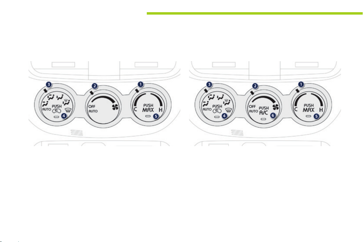
Heating / Ventilation
The heating and ventilation can be used as soon as the "Ready" lamp
is on.
Adjustments can be made manually or automatically.
1. Temperature
2. Air flow
3. Air distribution
Air conditioning
The air conditioning can be used as soon as the "Ready" lamp is on.
4. Exterior air intake / Interior air recirculation
5. "Max" button
6. Air conditioning On / Off
42
Page 45
Comfort
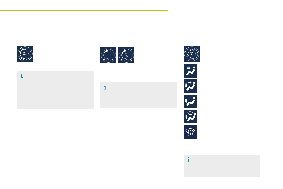
1. Temperature adjustment
F Turn the dial from blue
(cold) to red (hot) to adjust
the temperature to your
requirements.
When the dial is placed on "●", the fan
air will be at ambient temperature.
If you move the dial to "●" while using
the heating or air conditioning, these
will stop immediately.
2. Air ow adjustment
F Turn the dial to the
right to increase air
flow and to the left
to reduce it.
With the dial in the "AUTO" position,
the air flow is adjusted automatically,
according to the interior temperature.
3. Air distribution adjustment
Place the dial in the desired
position to distribute air to:
central and side vents,
central, side and footwell vents,
footwells,
windscreen, side windows and
footwells,
windscreen and side windows.
The air distribution can be adapted by placing
the dial in an intermediate position.
With the dial in the "AUTO" position, air
distribution is adjusted automatically,
according to the temperature selected.
3
43
Page 46
Comfort
4. Air intake / Air recirculation
The intake of exterior air prevents the formation
of mist on the windscreen and side windows.
The recirculation of interior air isolates the
passenger compartment from exterior odours
and smoke.
Return to exterior air intake as soon as possible
to prevent deterioration of the the air quality
and the formation of mist.
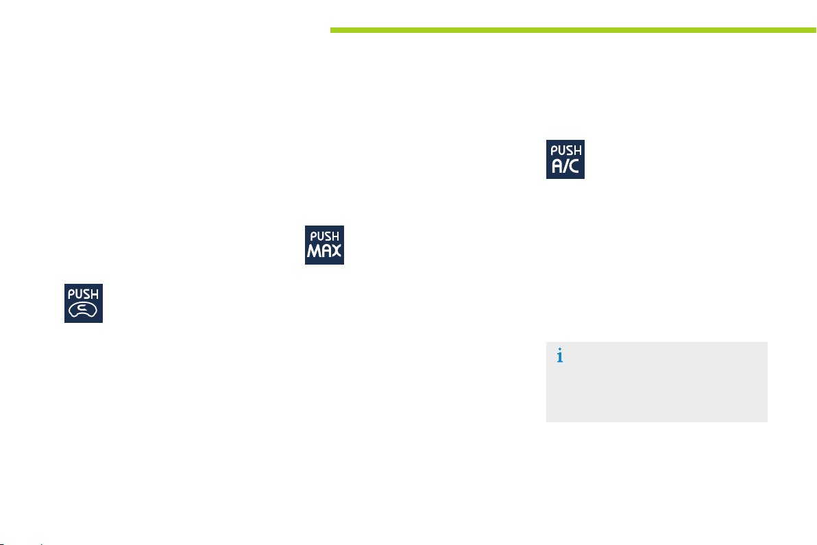
F Press this button to recirculate
the interior air. The indicator
lamp comes on to confirm this.
F Press the button again to permit
the intake of exterior air. The
indicator lamp switches off to
confirm this.
5. "MAX" button
This button allows the passenger compartment
to be quickly heated or cooled. It only works
when the air flow control is not in
the "OFF" position.
Press this button. The corresponding
indicator lamp comes on.
The place the temperature control in the
desired position:
- on "●" for maximum ventilation,
- between "●" and "H" for maximum heating,
- between "C" and "●" for maximum air
conditioning.
6. Air conditioning On / Off
The air conditioning is designed to
operate effectively in all seasons,
with the windows closed.
It enables you to:
- lower the temperature, in summer,
- increase the effectiveness of the demisting
in winter, above 3 °C.
Switching on
F Press the "A/C" button, the associated
indicator lamp comes on.
The air conditioning does not operate when
the air flow adjustment is set to off.
To obtain cool air sooner, you can use
air recirculation for a few moments.
Then return to the intake of exterior air.
Switching off
F Press the "A/C" button again, the
associated indicator lamp goes off.
Switching off may result in some discomfort
(humidity, misting).
44
Page 47
Comfort
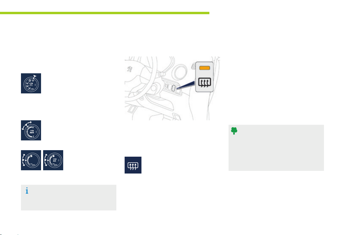
Front demist defrost
Front demisting-defrosting can be used as
soon as the "Ready" lamp is on.
Place the air distribution control in
this position.
The intake of exterior air is selected (indicator
lamp off) and depending on equipment, the air
conditioning starts running (indicator lamp on).
Place the temperature control
between "●" and "H".
Place the air flow control
in the desired position.
For rapid demisting - defrosting, you
can also press the "MAX" button.
Rear screen demist - defrost
The control button is located on the dashboard, to the right of the steering wheel.
Switching off
The demisting/defrosting switches off automatically
to prevent an excessive electric consumption.
F It is possible to stop the demisting/
defrosting operation before it is
switched off automatically by pressing
the button again. The indicator lamp
associated with the button goes off.
Switching on
Rear screen demisting/defrosting can only
operate when the "Ready" lamp is on.
F Press this button to demist/
defrost the rear screen and
(depending on version) the
door mirrors. The indicator
lamp associated with the button
comes on.
Switch off the demisting/defrosting
of the rear screen and door mirrors
as soon as appropriate, so as to limit
electrical consumption and optimise the
range of the vehicle.
3
45
Page 48
Driving
A few driving recommendations
Observe the driving regulations at all times and
remain vigilant whatever the traffic conditions.
Pay close attention to the traffic and keep your
hands on the wheel so that you are ready to
react at any time to any eventuality.
On a long journey, a break every two hours is
strongly recommended.
In difficult weather, drive smoothly, anticipate
the need to brake and increase the distance
from other vehicles.
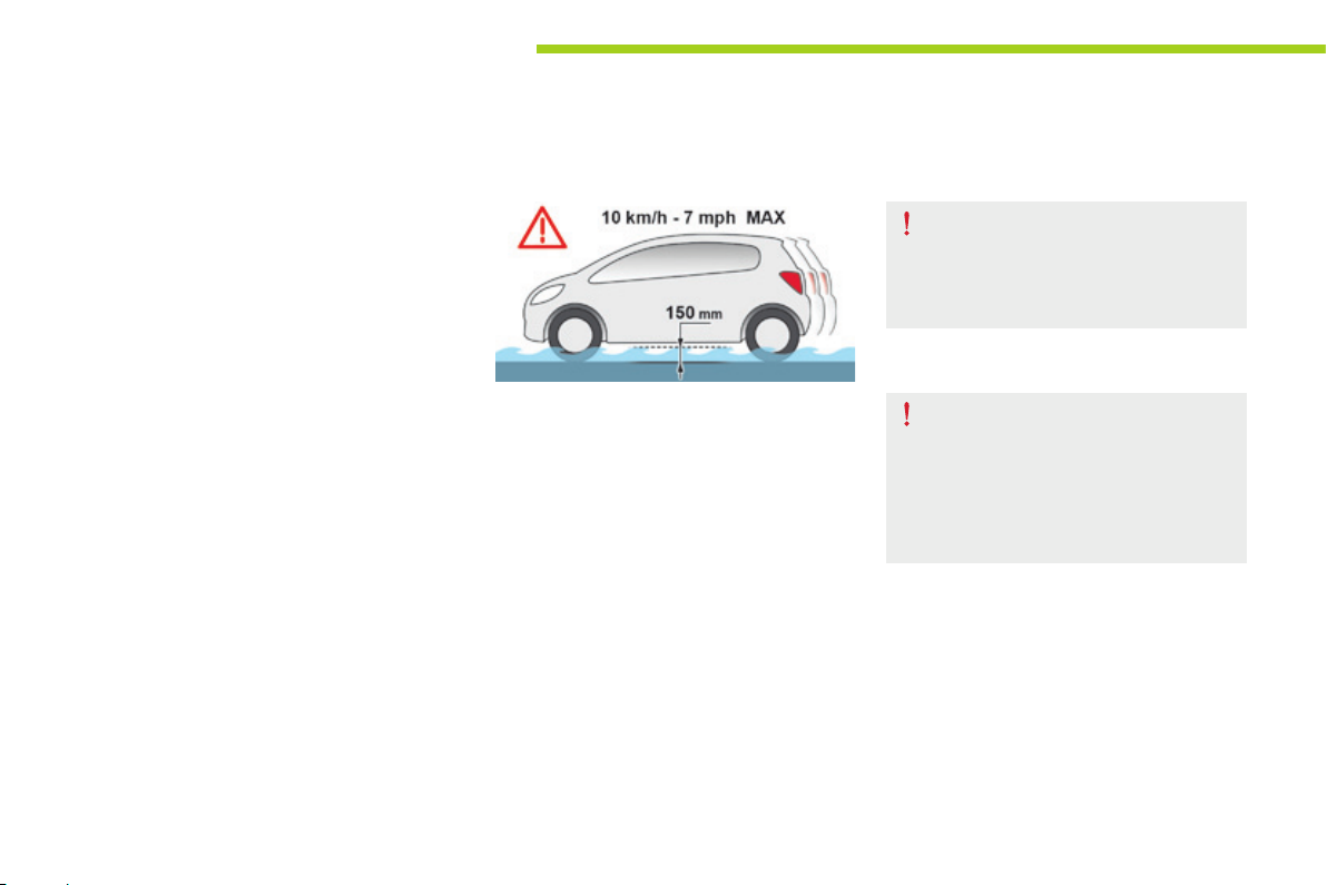
Driving on flooded roads
We strongly advise against driving on flooded
roads, as this could cause serious damage
to the drive train, as well as to the electrical
systems of your vehicle.
If you are obliged to drive through water:
- check that the depth of water does not
exceed 15 cm, taking account of waves
that might be generated by other users,
- drive as slowly as possible; do not exceed
6 mph (10 km/h),
- do not stop and do not switch off the motor.
On leaving the flooded road, as soon as
circumstances allow, make several light brake
applications to dry the brake discs and pads.
If in doubt on the state of your vehicle, contact
a PEUGEOT dealer or a qualified workshop.
Important!
Never drive with the parking brake
applied - Risk of overheating and
damage to the braking system!
Never leave a vehicle unsupervised
with the motor switched on. If you have
to leave your vehicle with the motor
switched on, apply the parking brake
and place the drive selector in
position N or P.
46
Page 49
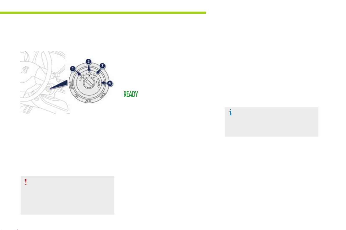
Starting - stopping the vehicle
Driving
Ignition switch
- Position 1: LOCK
The steering is locked.
- Position 2: ACC
The ancillaries (radio, 12 V socket...) can
be used.
- Position 3: ON
Ignition on.
- Position 4: START
"Ready" lamp on.
Motor ready to drive the vehicle.
If you use the ancillaries for a prolonged
period (with the key in the ACC position),
you risk discharging the ancillaries
battery. Starting your vehicle will then no
longer be possible. Be aware.
Starting Stopping
F Check that the drive selector is in
position P.
F Insert the key in the ignition switch.
F Turn the key to position 4 (START).
F Hold it in this position for a few
seconds until the "READY" lamp
comes on accompanied by an
audible signal.
F Release the key.
The key returns automatically to
position 3 (ON).
F Stop the vehicle.
F Keep your foot on the brake pedal.
F Place the drive selector in position P.
F Apply the parking brake.
F Turn the key to position 1 (LOCK).
F Remove the key from the ignition switch.
Do not attach any heavy objects to the
key as this could weigh down on it when
in the ignition switch and cause a fault.
4
47
Page 50
Driving
Parking brake
48
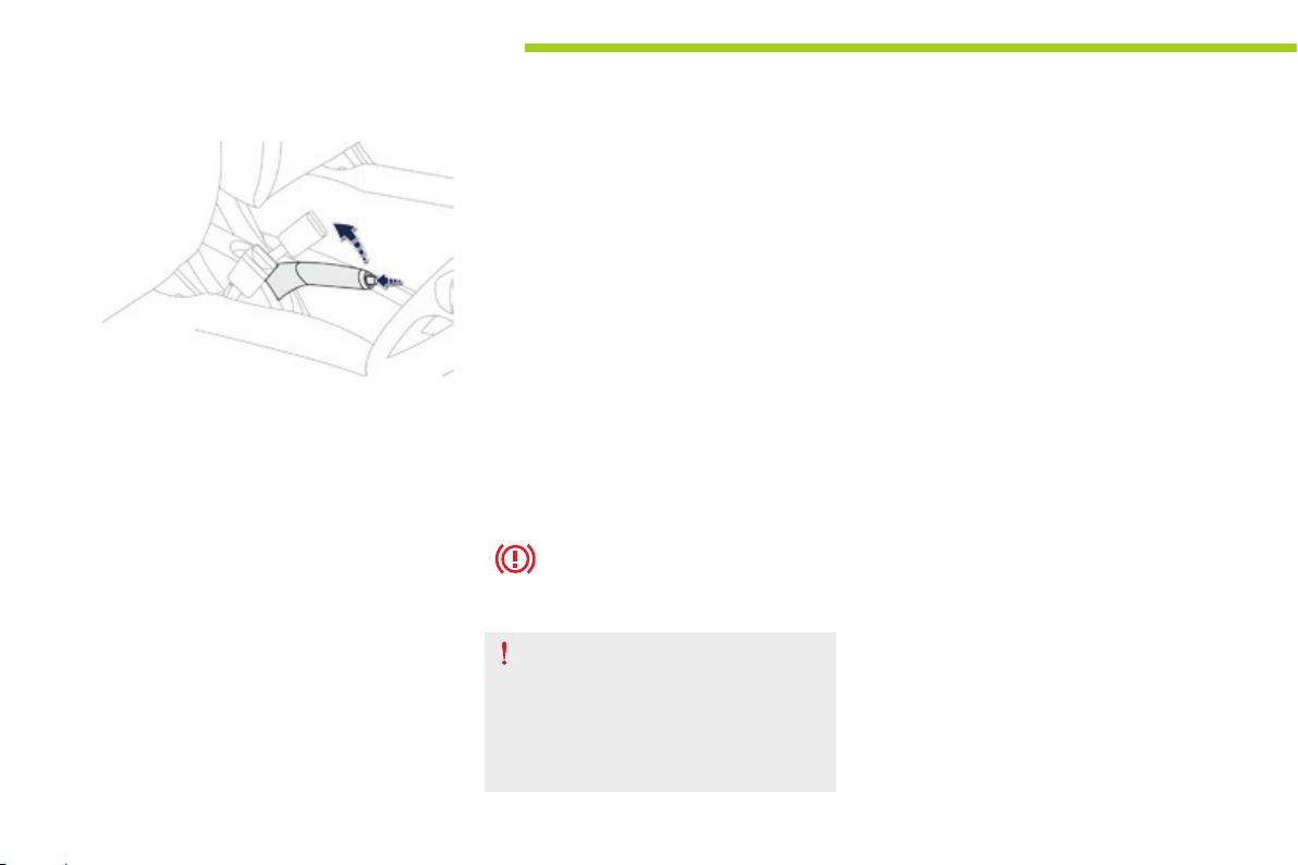
Applying
F Pull the parking brake lever fully up to
immobilise your vehicle.
Releasing
F Pull the parking brake lever up slightly,
press the release button then lower the
lever fully.
When the vehicle is being driven, if
the parking brake is still on or has
not been fully released, this warning
lamp comes on.
When parking on a slope, direct your
wheels against the kerb, apply the
parking brake, place the drive selector
in position P and switch off the ignition.
Page 51
Drive selector
Driving
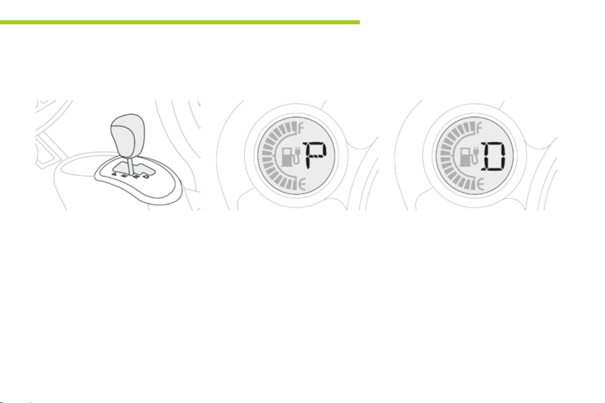
Selector positions
P. Park.
This position is used for starting the vehicle.
To come out of the P position, you must have
your foot on the brake.
R. Reverse.
N. Neutral.
D. Drive (Forward).
Displays in the instrument panel
When you move the drive selector through the
grille to select a position, the corresponding
indicator is displayed in the instrument panel.
Moving off
4
With the motor running, P appears in the
instrument panel screen.
F Press the brake pedal to come out of
position P.
F Select forward (D) or reverse (R) gear.
F Release the parking brake.
F Take your foot off the brake pedal, the
vehicle then moves off slowly to facilitate
manoeuvring.
F Accelerate to go forwards or backwards.
F "D" or "R" appears in the instrument panel
screen.
49
Page 52

Driving
Parking the vehicle
To stop the motor, you must select position P.
You must apply the parking brake to immobilise
the vehicle.
To remove the key from the ignition switch, the
drive selector must be in position P.
To tow your vehicle, the drive selector
must be in position N, refer to "Practical
Information".
50
Page 53
Lighting controls
Main lighting
The various front and rear lamps of the vehicle
are designed to adapt the lighting progressively
in relation to the climatic conditions and so
ensure the best visibility for the driver:
- sidelamps, to be seen,
- dipped beam headlamps to see without
dazzling other drivers,
- main beam headlamps to see clearly when
the road is clear.
Additional lighting
Other lamps are provided to fulfil the
requirements of particular driving conditions:
- a rear foglamp to be seen from a distance,
- front foglamps for even better visibility,
- daytime running lamps to be seen during
the day.
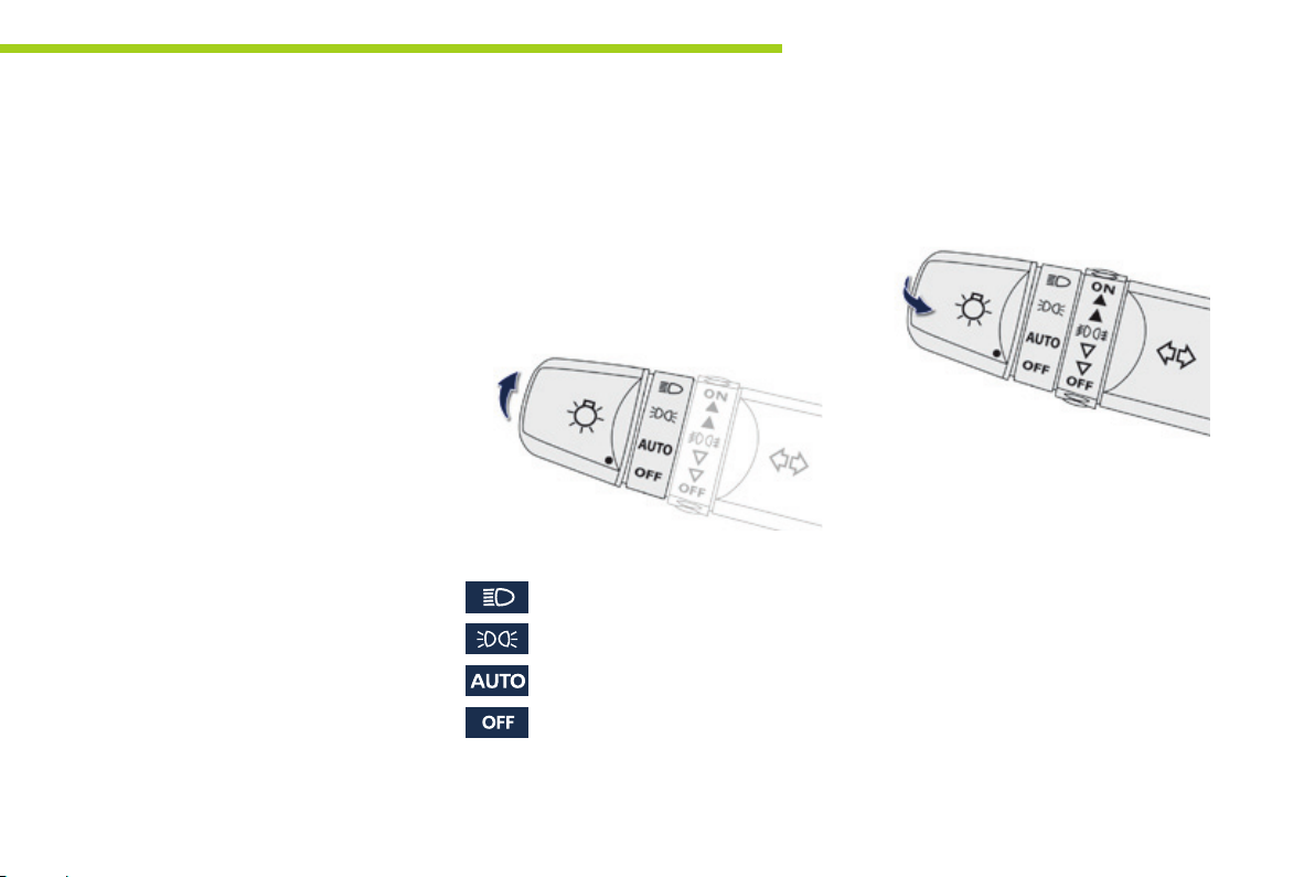
Selection ring for main lighting
mode
Turn the ring to position the symbol required
facing the mark.
Dipped or main beam headlamps.
Sidelamps only.
Automatic illumination of headlamps.
Lighting off.
Visibility
5
Stalk for switching headlamp beam
Pull the stalk to switch the lighting between
dipped / main beam headlamps.
In the lighting off and sidelamps modes,
the driver can switch on the main beam
headlamps temporarily ("headlamp flash") by
maintaining a pull on the stalk.
Displays
Illumination of the corresponding indicator lamp
in the instrument panel confirms the lighting
switched on.
51
Page 54
Visibility
Front and rear foglamps
52
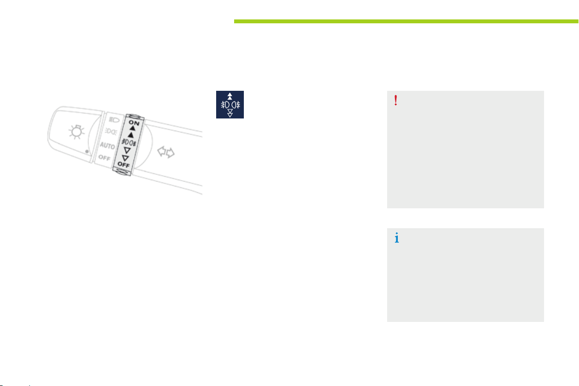
Foglamps selection ring.
The foglamps operate with the sidelamps and
dipped and main beam headlamps.
Front and rear foglamps.
F To switch on the front foglamps, turn the
ring forwards once.
F To switch on the rear foglamp, turn the ring
forwards twice.
F To switch off the rear foglamp, turn the ring
rearwards twice.
F To switch off the front foglamps, turn the
ring rearwards once.
The ring returns to its initial position
automatically.
The rear foglamp is switched off automatically
when you switch off the sidelamps, or the
dipped or main beam headlamps.
In good or rainy weather, both day
and night, the front foglamps and the
rear foglamp is prohibited. In these
situations, the power of its beam may
dazzle other drivers.
Do not forget to switch off the front
foglamps and the rear foglamp when
they are no longer necessary.
Lighting on reminder
There is an audible signal when the
driver's door is opened, to warn the
driver if the vehicle lighting is on, with
the ignition off.
Switching off the lighting stops the
audible signal.
Page 55
Headlamp
Visibility
Daytime running l amps
Special daytime lighting so that the vehicle can
be seen more easily.
The daytime running lamps come on
automatically when starting the motor,
if no other lighting is on.
They cannot be deactivated.
Although these lamps are located in
the same unit as the front foglamp, they
operate with a specific bulb.
Their use is covered by road vehicle
lighting regulations.
Automatic illumination of headlamps
Automatic illumination of headlamps
With the main lighting control ring in the AUTO
position, the sidelamps and dipped beam headlamps
come on automatically , without any action by the
driver, when a low level of ambient light is detected.
When the light returns to a sufficient level or the
wipers are switched off, the lighting is switched off
automatically.
The sensor is located at the base of the windscreen.
In foggy weather or in snow, the
sunshine sensor may detect sufficient
light. The lighting will not come on
automatically.
Do not cover the sunshine sensor, the
associated functions will no longer be
controlled.
Automatic lighting off
When the lighting stalk is in the "AUTO"
position, if the ignition switch is in the "LOCK"
or "ACC" position or if the key has been
removed, the lighting switches off automatically
when the driver's door is opened.
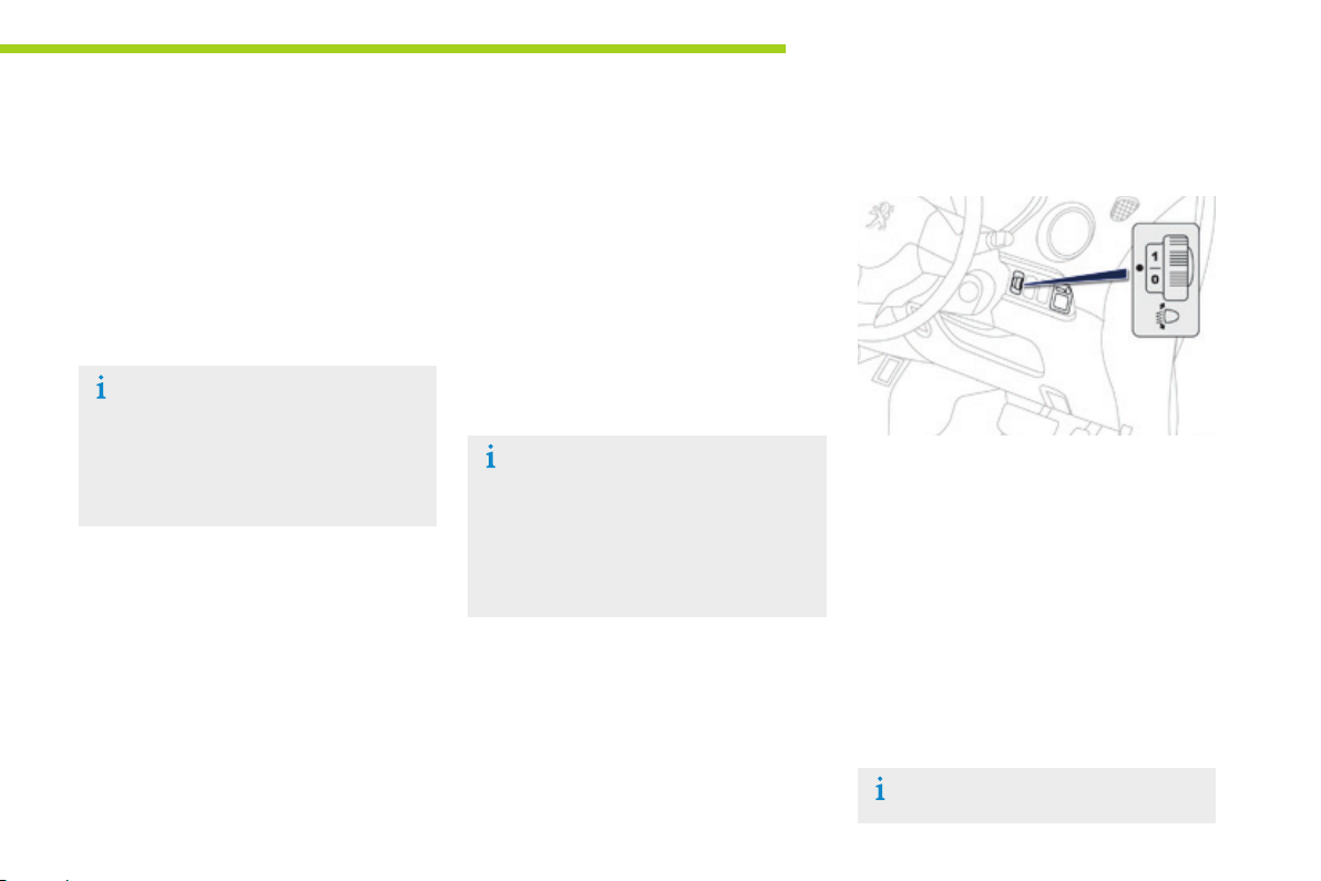
adjustment
5
To avoid causing a nuisance to other road
users, the height of the halogen headlamps
should be adjusted according to the load in the
vehicle.
0. Driver only or driver + 1 front passenger.
1 or 2. 4 people (including the driver).
3. 4 people (including the driver) + maximum
authorised load.
4. Driver + maximum authorised load.
The initial setting is position "0".
53
Page 56
Visibility
Wiper control
Windscreen wipers
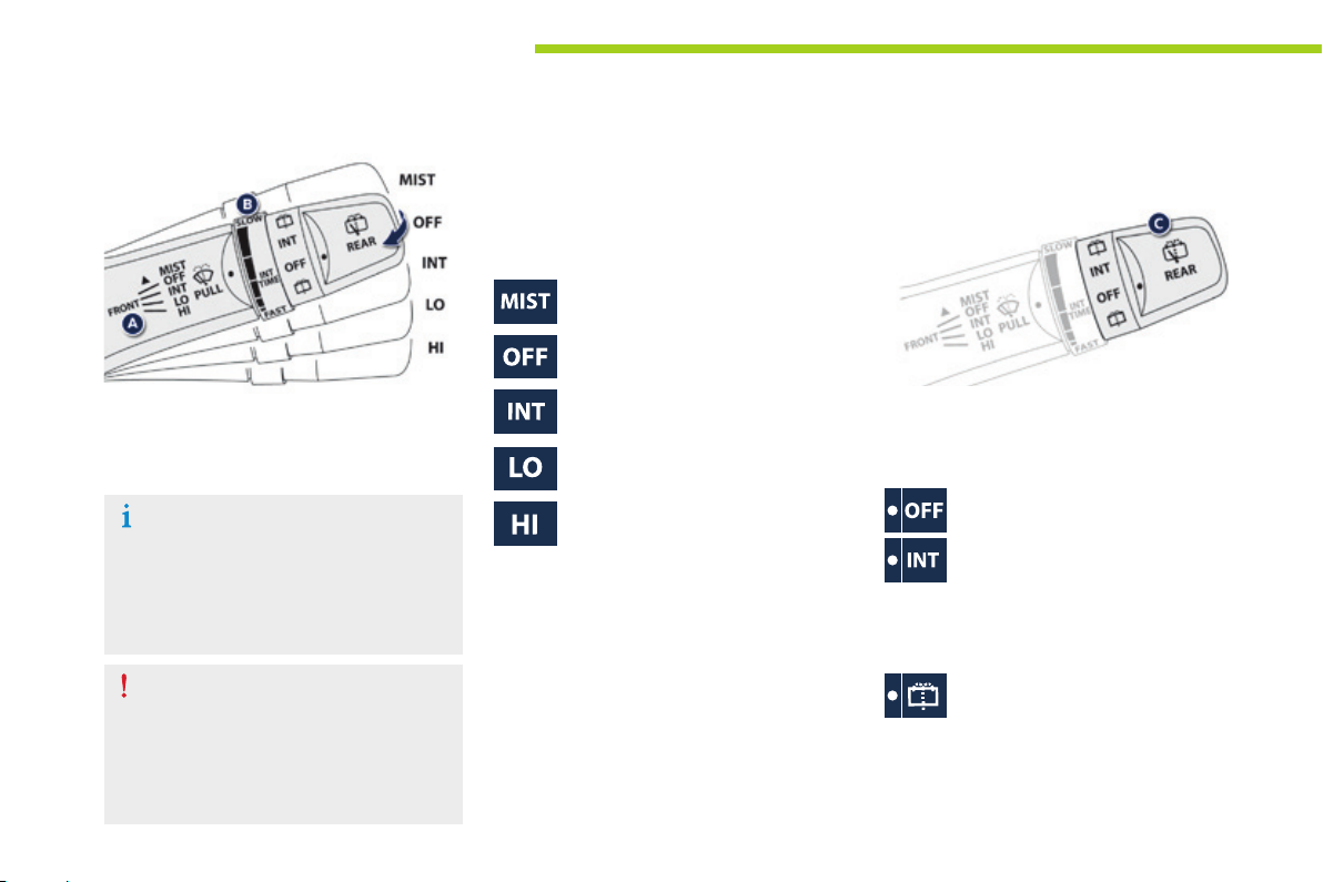
A. Wiping speed selection stalk: raise or lower
the stalk to the desired position.
Single wipe.
Park.
54
The wipers are controlled directly by the driver
by means of the stalk A and its ring B.
In wintry conditions, remove snow,
ice or frost present on the windscreen,
around the wiper arms and blades and
the windscreen seal, before operating
the wipers.
Do not operate the wipers on a dry
windscreen. Under extremely hot or
cold conditions, ensure that the wiper
blades are not stuck to the windscreen
before operating the wipers.
Intermittent (the speed can be set
manually).
Slow.
Fast.
B. Intermittent operation adjustment ring.
F Turn this ring to increase or reduce the
wiping frequency in intermittent mode.
Windscreen wash
Pull the wiper stalk towards you. The
windscreen wash, then the windscreen wipers,
operate for a pre-determined time.
Rear wip er
C. Rear wiper selection ring.
Park.
Intermittent wipe.
The wiper wipes twice then switches to
intermittent mode with an interval of a few
seconds.
Wipe with screenwash.
Keep the ring in this position to operate the
screenwash with several wipes of the wiper.
Page 57
Courtesy lamp
Visibility
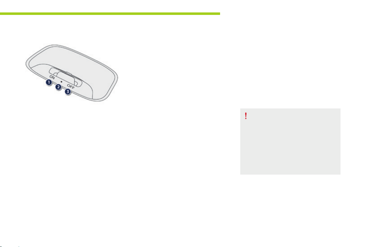
Position 1 "ON"
The courtesy lamp is permanently on.
Position 2 "●"
The courtesy lamp comes on when opening
a door or the boot; when the door or boot is
closed again, the lighting gradually dims for a
few seconds before going off.
However, the courtesy lamp is switched off
immediately when the doors and boot are
closed and you lock the vehicle from the inside
or using the remote control.
Position 3 "OFF"
The courtesy lamp is permanently off.
Before leaving the vehicle, ensure that
the courtesy lamp is not on.
If left on, it discharges the ancillaries
battery, even if the main battery is
charged or on charge.
Starting your vehicle will then no longer
be possible.
5
55
Page 58
Safety
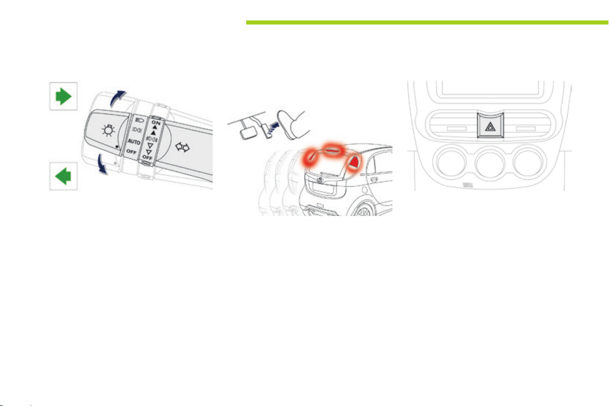
Direction indicators
Selection of the left or right direction indicators
to signal a change of direction of the vehicle.
F Left: lower the lighting stalk beyond the
point of resistance.
F Right: raise the lighting stalk beyond the
point of resistance.
Automatic operation of brake lamps
The brake lamps come on automatically when
you release the accelerator pedal.
This does not happen in all cases and depends
on the rate of deceleration.
Hazard warning lamps
A visual warning by means of the direction
indicators to alert other road users to a vehicle
breakdown, towing or accident.
F Press this button, the direction indicators
flash.
They can operate with the ignition off.
56
Page 59
Safety
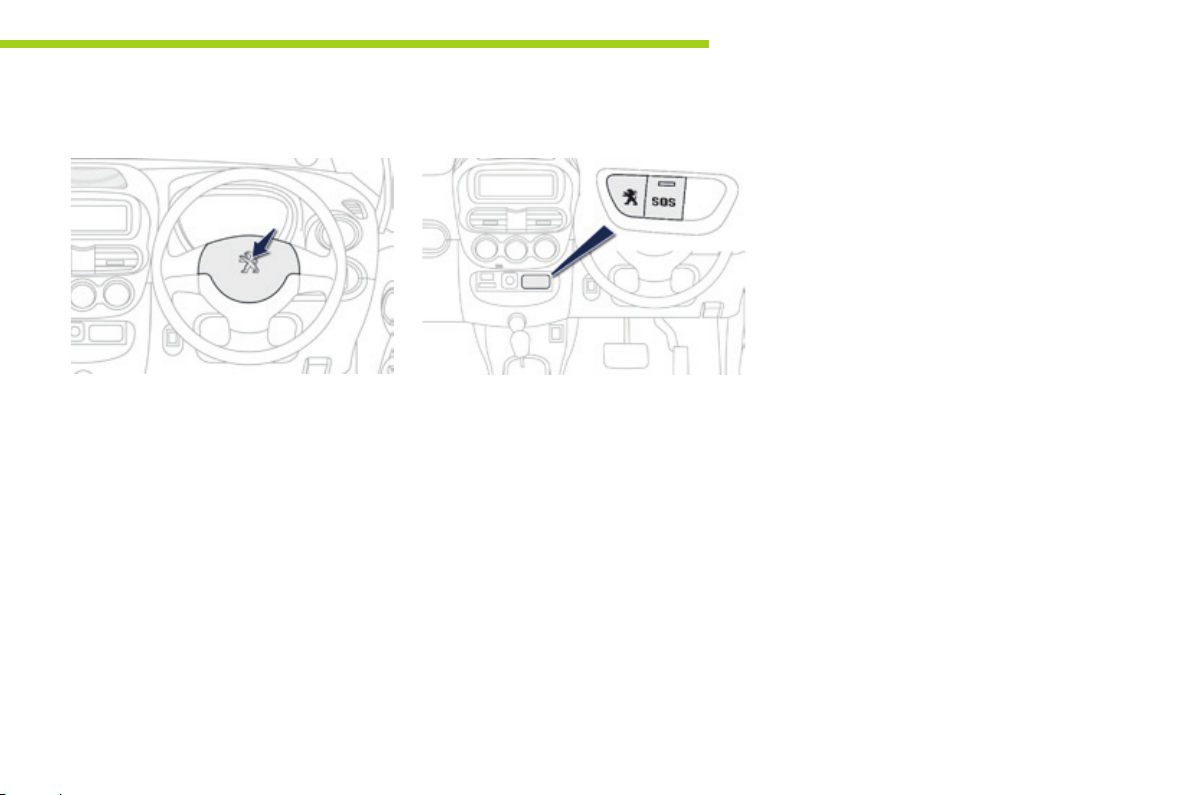
Horn
F Press the central part of the steering
wheel.
Emergency or assistance call
This system allows you to make an emergency
or assistance call to the emergency services or
to the dedicated PEUGEOT service.
For more information on the use of this
function, refer to the "Audio equipment and
telematics" section.
6
57
Page 60

Safety
Under-ination detection
System which continuously and automatically
checks the pressures of the four tyres after
switching on the ignition.
A pressure sensor is located in the valve of
each tyre.
The system triggers an alert if a drop in
pressure is detected in one or more tyres,
compared to the reference pressure registered
in the system. This reference pressure must be
reinitialised every time the tyre pressures are
adjusted or a wheel changed.
The system operates on condition that sensor
identifiers have first been memorised in the
system by a PEUGEOT dealer or a qualified
workshop.
You can memorise two sets of tyres
(for example: wheels with "standard" tyres and
wheels with "winter" tyres).
The tyre under-inflation detection
system is an aid to driving which does
not replace the need for vigilance on
the part of the driver.
This system does not avoid the need to
check the tyre pressures regularly and
before a long journey.
Driving with under-inflated tyres
adversely affects road holding,
extends braking distances and causes
premature tyre wear, particularly under
arduous conditions (vehicle loaded,
high speed, long journey).
Driving with under-inflated tyres
increases fuel consumption.
The tyre pressures for your vehicle can
be found on the tyre pressure label (see
the "Identification markings" section).
The tyre pressures must be checked
when the tyres cold (vehicle stopped
for 1 hour or after driving for less then
6 miles (10 km) at moderate speed).
Otherwise, add 0.3 bar to the values
indicated on the label.
58
Page 61
Safety
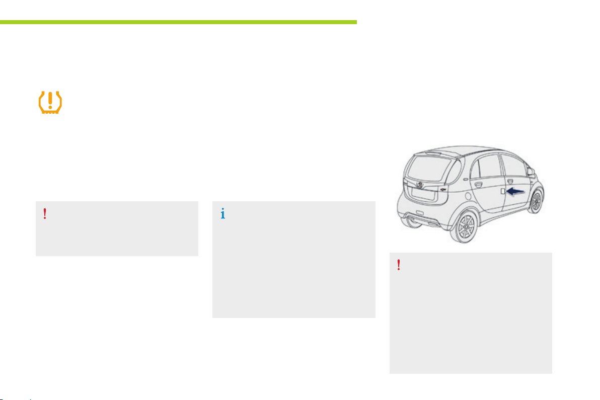
Under-inflation alert
The alert is given by the fixed
illumination of this warning lamp.
F Reduce speed, avoid sudden steering
movements or harsh brake applications.
F Stop as soon as it is safe to do so.
The loss of pressure detected does not
always lead to visible deformation of the
tyre. Do not rely on just a visual check.
F Check the four tyre pressures when cold,
using the compressor from the temporary
puncture repair kit.
If it is not possible to check the tyre
pressures at the time, drive carefully at
reduced speed.
or
F In the event of a puncture, use the
temporary puncture repair kit.
The alert is maintained until the
reference pressure is reinitialised after
the inflation, repair or replacement of
the tyres concerned. In the event of
the repair or replacement of tyres, the
sensor identifiers must be registered in
the system by a PEUGEOT dealer or a
qualified workshop.
Reinitialising the reference
pressure
The system must be reinitialised after any
adjustment of tyre pressures and after
changing one or more wheels.
6
Before reinitialising the system, ensure
that the pressures in the four tyres are
suitable for the conditions of use of the
vehicle and as specified on the tyre
pressure label.
The under-inflation detection system
cannot warn of an incorrect pressure at
the time of reinitialisation.
59
Page 62
Safety
Operating fault
60
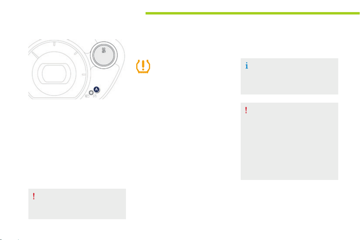
The reinitialisation instruction is entered in
the instrument panel screen screen, with the
ignition on and the vehicle stationary.
F Press button A select the function
F Press and hold button A for at least
3 seconds to reinitialise the under-inflation
detection system.
Reinitialisation of the system is confirmed
by the flashing of the warning lamp in the
instrument panel.
You then have to drive about 100 metres before
the warning lamp goes off.
The under-inflation alert is only reliable
if the system has been reinitialised
with the four tyre pressures correctly
adjusted.
The flashing and then fixed illumination
of the under-inflation warning lamp
indicates a fault with the system.
In this case, monitoring of the tyre pressures is
not assured.
This alert is also displayed if:
- one or more wheels is not fitted with a
sensor,
- a wireless device operating on the same
frequency is close to the vehicle,
- there are accumulations of snow or ice in
the wings or wheels,
- the state of charge of the tyre pressure
monitoring system battery is too low,
- the wheel sensor identifiers have not been
memorised in the system by a PEUGEOT
dealer or a qualified workshop.
Go to a PEUGEOT dealer or a qualified
workshop to have the system checked
or, following the repair of a puncture, to
have the original wheel, equipped with a
sensor, refitted.
Any tyre repair or replacement on a
wheel fitted with this system must be
carried out by a PEUGEOT dealer or a
qualified workshop.
If you fit the second set of tyres
memorised in the system, a fault will
be signalled until the second set is
selected in the configuration menu.
Page 63
Managing sets of wheels
and tyres
If you have had a second set of wheels and
tyres registered by a PEUGEOT dealer or a
qualified workshop, every time you change the
set of wheels (fitting a set of winter tyres, for
example), you must select the set you have just
fitted in the configuration menu.
After fitting the new set of wheels and
tyres, you should check and adjust the
tyre pressures to the values specified
on the tyre pressure label (see the
"Identification markings" section).
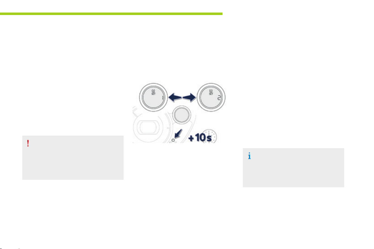
Selection of the other set of wheels and tyres
is is done via the instrument panel screen, with
the ignition on and the vehicle stationary.
F Press button A to select the function.
F Press and hold button A button for more
than 10 seconds to change successively
from set of wheels and tyres 1 to set of
wheels and tyres 2 or the other way round.
Safety
6
The system automatically reinitialises
the reference pressure based on the
pressure in the new set (the underinflation detection warning lamp flashes
during the operation).
61
Page 64

Safety
Braking assistance systems
Group of supplementary systems which help
you to obtain optimum braking in complete
safety in emergency situations:
- anti-lock braking system (ABS),
- electronic brake force distribution (EBFD),
- emergency braking assistance (EBA).
Anti-lock braking system
and electronic brake force
distribution
Linked systems which improve the stability and
manoeuvrability of your vehicle when braking,
in particular on poor or slippery surfaces.
Activation
The anti-lock braking system comes into
operation automatically when there is a risk of
wheel lock.
Normal operation of the ABS may make itself
felt by slight vibration of the brake pedal.
When braking in an emergency, press
very firmly without releasing the
pressure.
62
Page 65
Operating fault
Vehicle stationary
Illumination of this warning lamp
indicates a malfunction of the antilock braking system, which could
result in a loss of control of the
vehicle when braking.
Contact a PEUGEOT dealer or a qualified
workshop.
The warning lamp comes on for a few
seconds when the ignition is switched
on (ON position). If it does not go off or
does not come on, contact a PEUGEOT
dealer or a qualified workshop.
Vehicle moving
Fixed illumination of this warning
lamp indicates a malfunction of
the anti-lock braking system which
could result in a loss of control of the
vehicle on braking.
You must stop as soon as it is safe to do so.
Contact a PEUGEOT dealer or a qualified
workshop.
Illumination of these two
warning lamps indicates a
malfunction of the electronic
brake force distribution
which could result in a loss of control of the
vehicle on braking.
You MUST stop as soon as it is safe to do so.
Contact a PEUGEOT dealer or a qualified
workshop.
When replacing wheels (tyres and rims),
ensure that they conform to the manufacturer's
recommendations.
Safety
Emergency brakin g assistance
System which, in an emergency, enables you
to obtain the optimum braking pressure more
quickly, thus reducing the stopping distance.
Activation
It is triggered by the speed at which the brake
pedal is pressed.
The effect of this is a reduction in the
resistance of the pedal and an increase in
braking efficiency.
When braking in an emergency, press
firmly without releasing the pressure.
6
63
Page 66
Safety
Trajectory control systems
Anti-slip regulation (ASR)
and electronic stability
programme (ESP)
The anti-slip regulation (also known as Traction
Control) optimises traction to limit wheel spin,
by acting on the brakes of the driving wheels
and on the engine.
The electronic stability programme acts on the
brake of one or more wheels and on the engine
to keep the vehicle on the trajectory required
by the driver, within the limits of the laws of
physics.
Activation
These systems are activated automatically
each time the vehicle is started.
They come into operation in the event of a grip
or trajectory problem.
This is indicated by flashing of this
symbol in the instrument panel.
Deactivation
In exceptional conditions (starting a vehicle
which is bogged down, stuck in snow, on soft
ground, ...), it may be advisable to deactivate
the ASR and ESP systems to regain grip.
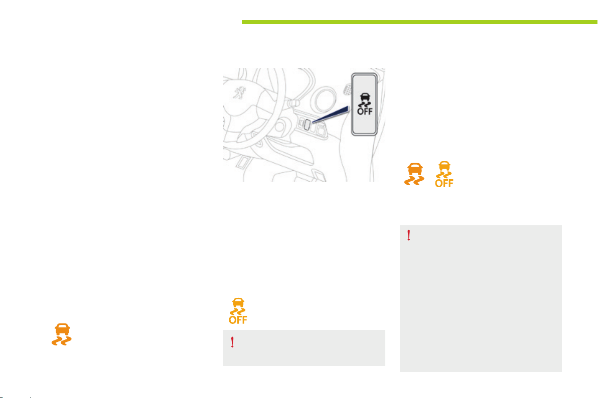
F Press this button button, located on the
dashboard to the right of the steering
wheel, until the corresponding symbol
appears in the instrument panel screen.
The display of this symbol indicates
that the ASR and ESP systems are
deactivated.
Excessive wheel spin may damage your
vehicle's differential.
Reactivation
These systems are not reactivated automatically.
F Press this button again to reactivate them
manually.
The symbol going off in the instrument panel
indicates the reactivation of the ASR and ESP
systems.
Operating fault
The display of this message in
the instrument panel indicates
a malfunction of these
systems.
Contact a PEUGEOT dealer or a qualified
workshop to have the ASR/ESP systems
checked.
The ASR/ESP systems offer should not
encourage the driver to take extra risks
or drive at high speed.
The correct functioning of these
systems depends on observation of
the manufacturer's recommendations
regarding the wheels (tyres and rims),
the braking components, the electronic
components and the assembly
and repair procedures used by the
PEUGEOT dealer network.
After an impact, have these systems
checked by a PEUGEOT dealer or a
qualified workshop.
64
Page 67
Seat belts
Front seat belts
Safety
The front seat belts are fitted with a
pretensioning and force limiting system.
This system improves safety in the front
seats in the event of a front or side impact.
Depending on the severity of the impact, the
pretensioning system instantly tightens the seat
belts against the body of the occupants.
The pretensioning seat belts are active when
the ignition is on.
The force limiter reduces the pressure of the
seat belt on the chest of the occupant, so
improving their protection.
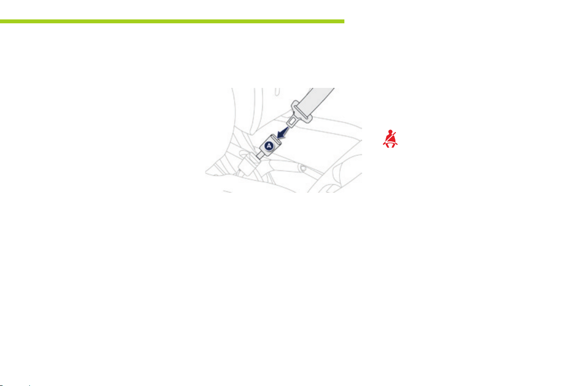
Fastening
F Pull the strap, then insert the tongue in the
buckle A.
F Check that the seat belt is fastened
correctly by pulling the strap.
Unfastening
F Press the red button on the buckle A.
Front seat belt not fastened /
unfastened warning lamp
When the ignition is switched on, this
warning lamp comes on accompanied
by an audible signal for a few seconds
if the driver and/or passenger has not
fastened their seat belt.
If the driver does not fasten their seat belt
within one minute after switching on the
ignition, the warning lamp flashes accompanied
by an intermittent audible signal.
After about 90 seconds, the warning lamp, the
audible signal and the display stop, and then
return until the driver fastens their seat belt.
If the seat belt is unfastened while the vehicle
is moving, you are warned by the same alerts.
6
65
Page 68
Safety
Rear seat belts
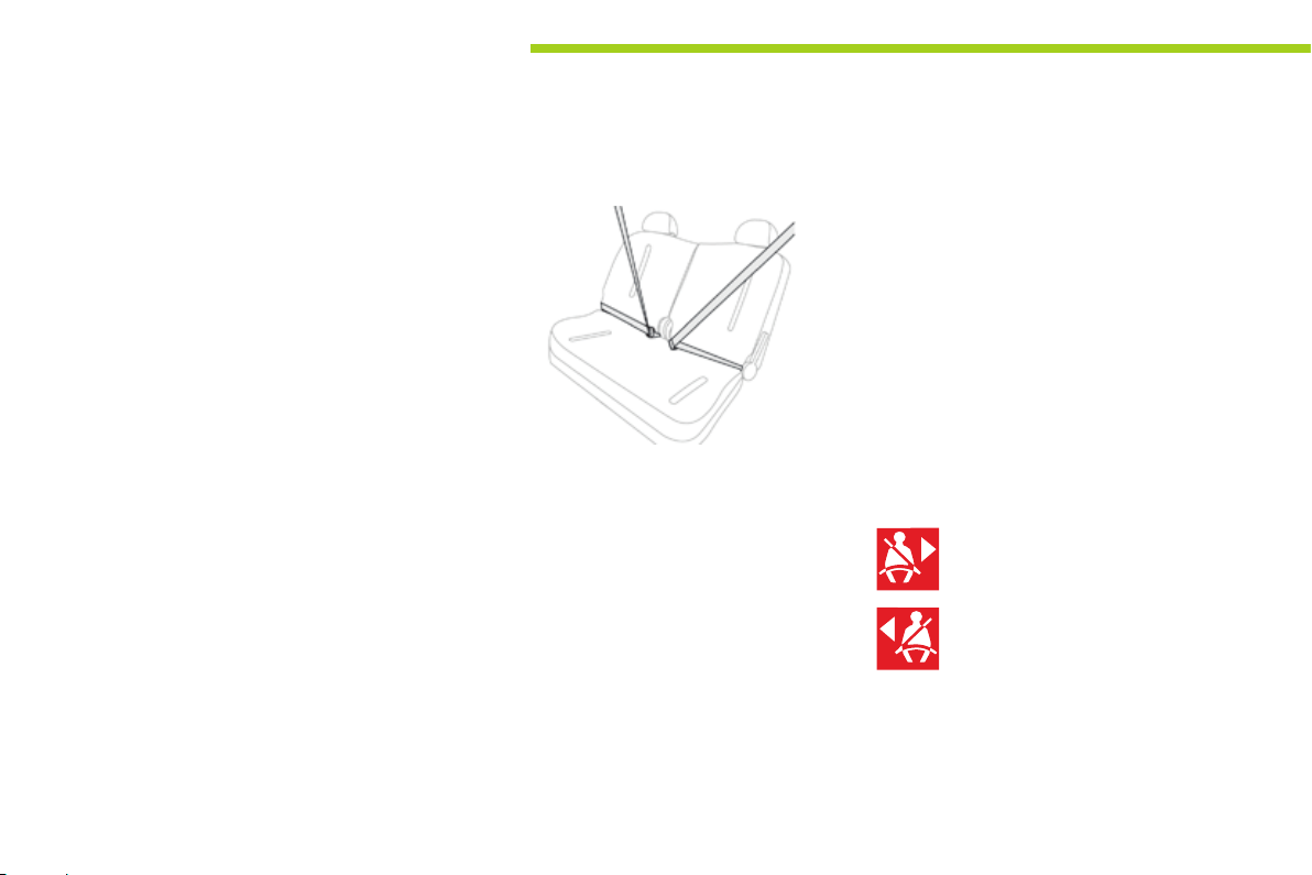
Each rear seat is fitted with a three-point inertia
reel seat belt.
66
Fastening
F Pull the strap, then insert the tongue in the
buckle.
F Check that the seat belt is fastened
correctly by pulling the strap.
Unfastening
F Press the red button in the buckle.
Seat belt unfastened warning
lamps
Right hand rear seat belt warning lamp.
Left hand rear seat belt warning lamp.
Illumination of one of these warning lamps in
the instrument panel indicates that one of the
rear passengers has unbuckled their seat belt.
Page 69

Safety
The driver must ensure that passengers use
the seat belts correctly and that they are all
restrained securely before setting off.
Wherever you are seated in the vehicle,
always fasten your seat belt, even for short
journeys.
Do not interchange the seat belt buckles as
they will not fulfil their role fully.
The seat belts are fitted with an inertia reel
permitting automatic adjustment of the
length of the strap to your size. The seat belt
is stowed automatically when not in use.
Before and after use, ensure that the seat
belt is reeled in correctly.
The lower part of the strap must be
positioned as low as possible on the pelvis.
The upper part must be positioned in the
hollow of the shoulder.
The inertia reels are fitted with an automatic
locking device which comes into operation in
the event of a collision, emergency braking
or if the vehicle rolls over. You can release
the device by pulling the strap firmly and
then releasing it so that it reels in slightly.
In order to be effective, a seat belt must:
- be tightened as close to the body as
possible,
- be pulled in front of you with a smooth
movement, checking that it does not
twist,
- be used to restrain only one person,
- not bear any trace of cuts or fraying,
- not be converted or modified to avoid
affecting its performance.
In accordance with current safety
regulations, for all repairs on your vehicle's
seat belts, go to a qualified workshop with
the skills and equipment needed, which a
PEUGEOT dealer is able to provide.
Have your seat belts checked regularly by a
PEUGEOT dealer or a qualified workshop,
particularly if the straps show signs of
damage.
Clean the seat belt straps with soapy
water or a textile cleaning product, sold by
PEUGEOT dealers.
After folding or moving a seat or rear bench
seat, ensure that the seat belt is positioned
and reeled in correctly.
Recommendations for children
Use a suitable child seat if the passenger is
less than 12 years old or shorter than one
and a half metres.
Never use the same seat belt to secure more
than one person.
Never allow a child to travel on your lap.
For more information, refer to the "Child
seats" section.
In the event of an impact
Depending on the nature and
seriousness of the impact, the
pretensioning device may be deployed
before and independently of the airbags.
Deployment of the pretensioners is
accompanied by a slight discharge of
harmless smoke and a noise, due to the
activation of the pyrotechnic cartridge
incorporated in the system.
In all cases, the airbag warning lamp comes on.
Following an impact, have the seat belts
system checked, and if necessary replaced,
by a PEUGEOT dealer or a qualified
workshop.
6
67
Page 70
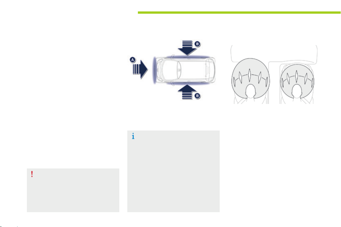
68
Safety
Airbags
The airbags have been designed to contribute
towards improving the safety of the occupants
in the event of violent collisions. They
supplement the action of the force-limiting seat
belts.
In this case, the electronic detectors record and
analyse the front and side impacts suffered in
the impact detection zones:
- in the event of a serious impact, the
airbags are deployed instantaneously
and contribute towards protecting the
occupants of the vehicle; immediately after
the impact, the airbags deflate rapidly so
that they do not hinder the visibility of the
occupants or their possible exit from the
vehicle,
- in the event of a minor impact or rear
impact and in certain roll-over conditions,
the airbags may not be deployed; the seat
belt alone contributes towards providing
your protection in these situations.
The airbags do not operate when the
ignition is off.
This equipment only operates once. If a
second impact occurs (during the same
or a subsequent accident), the airbag
will not be deployed again.
Impact detection zones
A. Front impact zone.
B. Side impact zone.
The deployment of one or more airbags
is accompanied by a slight discharge
of smoke and a noise, due to the
activation of the pyrotechnic cartridge
incorporated in the system.
This smoke is not harmful, but sensitive
individuals may experience some
irritation.
The noise of the detonation related to
the deployment of one or more airbags
may result in a slight loss of hearing for
a short time.
Front airbags
System which protects the head and chest of
the driver and front passenger in the event of a
front impact.
The driver's airbag is fitted in the centre of the
steering wheel; the front passenger's airbag is
fitted in the dashboard above the glove box.
Deployment
The airbags are deployed, except the
passenger's front airbag if it is deactivated,
in the event of a serious front impact applied
to all or part of the front impact zone A, in
the longitudinal centreline of the vehicle on a
horizontal plane and directed from the front to
the rear of the vehicle.
The front airbag inflates between the front
occupant of the vehicle and the dashboard to
cushion their forward movement.
Page 71
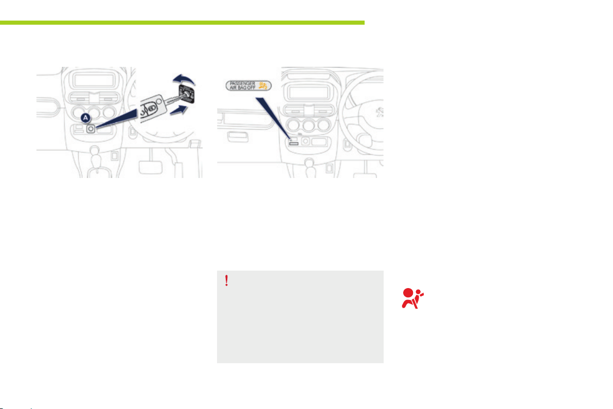
Safety
Deactivation
Only the front passenger's airbag can be
deactivated:
F with the ignition off, insert the key in the
passenger airbag deactivation switch A,
F turn it to the "OFF" position,
F remove the key.
This warning lamp comes on in the centre
console when the ignition is on and until the
airbag is reactivated.
To ensure the safety of your child, the
passenger airbag must be deactivated
when you install a rearward facing child
seat on the front passenger seat.
Otherwise, the child would risk being
seriously injured or killed if the airbag
were deployed.
Reactivation
When you remove the child seat, turn
switch A to the "ON" position to reactivate the
airbag and so ensure the safety of your front
passenger in the event of an impact.
The associated warning lamp goes off.
Operating fault
If this warning lamp comes on in the
instrument panel, contact a PEUGEOT
dealer or a qualified workshop without
delay to have the system checked. The
airbags may no longer be deployed in
the event of a serious impact.
In this case, do not install a child seat
or seat an adult on the front passenger
seat.
6
69
Page 72
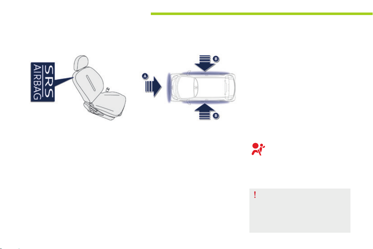
Safety
Lateral airbags
Deployment
Each curtain airbag is deployed at the same
time as the corresponding lateral airbag in the
event of a serious side impact applied to all or
part of the side impact zone B, perpendicular
to the longitudinal centreline of the vehicle on a
horizontal plane and directed from the outside
towards the inside of the vehicle.
The curtain airbag inflates between the front or
rear occupant of the vehicle and the windows.
70
System which protects the driver and front
passenger in the event of a serious side impact
in order to limit the risk of injury to the chest,
between the hip and the shoulder.
Each lateral airbag is fitted in the seat backrest
frame, door side.
Deployment
A lateral airbag is deployed unilaterally in the
event of a serious side impact applied to all or
part of the side impact zone B, perpendicular
to the longitudinal centreline of the vehicle on a
horizontal plane and directed from the outside
towards the inside of the vehicle.
The lateral airbag inflates between the hip and
shoulder of the front occupant of the vehicle
and the corresponding door trim panel.
Impact detection zones
A. Front impact zone.
B. Side impact zone.
Curtain airbags
System which protects the driver and
passengers in the event of a serious side
impact in order to limit the risk of injury to
the head.
Each curtain airbag is fitted in the pillars
and the upper section of the passenger
compartment.
Operating fault
If this warning lamp comes on in
the instrument panel, contact a
PEUGEOT dealer or a qualified
workshop to have the system
checked. The airbags may no longer
be deployed in the event of a serious
impact.
In the event of a minor impact or bump
on the side of the vehicle or if the
vehicle rolls over, the airbag may not be
triggered.
In the event of a rear or front collision,
the airbag is not triggered.
Page 73
For the airbags to be fully effective, observe the following safety rules:
Safety
Sit in a normal upright position.
Wear a correctly adjusted seat belt.
Do not leave anything between the
occupants and the airbags (a child, pet,
object...). This could hamper the operation of
the airbags or injure the occupants.
After an accident or if the vehicle has been
stolen or broken into, have the airbag
systems checked.
All work on the airbag system must be
carried out by a PEUGEOT dealer or a
qualified workshop.
Even if all of the precautions mentioned
are observed, a risk of injury or of minor
burns to the head, chest or arms when an
airbag is deployed cannot be ruled out. The
bag inflates almost instantly (within a few
milliseconds) then deflates within the same
time discharging the hot gas via openings
provided for this purpose.
Front airbags
Do not drive holding the steering wheel by its
spokes or resting your hands on the centre
part of the wheel.
Passengers must not place their feet on the
dashboard.
Do not smoke as deployment of the airbags
can cause burns or the risk of injury from a
cigarette or pipe.
Never remove or pierce the steering wheel or
hit it violently.
Do not fit or attach anything to the steering
wheel or dashboard, this could cause
injuries with deployment of the airbags.
Lateral airbags
Use only approved covers on the seats,
compatible with the deployment the lateral
airbags. For information on the range of seat
covers suitable for your vehicle, you can
contact a PEUGEOT dealer.
Refer to the "Accessories" section.
Do not fix or attach anything to the seat
backs (clothing...). This could cause injury
to the chest or arms if the lateral airbag is
deployed.
Do not sit with the upper part of the body any
nearer to the door than necessary.
Curtain airbags
Do not fix or attach anything to the roof. This
could cause injury to the head if the curtain
airbag is deployed.
If fitted on your vehicle, do not remove the
grab handles installed on the roof, they play
a part in securing the curtain airbags.
6
71
Page 74

Child safety
General points relating to child seats
Although one of PEUGEOT main criteria when designing your vehicle, the safety of your children
also depends on you.
72
For maximum safety, please observe the
following recommendations:
- in accordance with European regulations,
all children under the age of 12 or less
than one and a half metres tall must
travel in approved child seats suited to
their weight, on seats fitted with a seat
belt or ISOFIX mountings*,
- statistically, the safest seats in your
vehicle for carrying children are the
rear seats,
- a child weighing less than 9 kg must
travel in the rearward facing position
both in the front and in the rear.
PEUGEOT recommends that children
should travel in the outer rear seats of
your vehicle:
- rearward facing up to the age of 3,
- forward facing over the age of 3.
* The regulations on carrying children are
specific to each country. Refer to the
legislation in force in your country.
Page 75
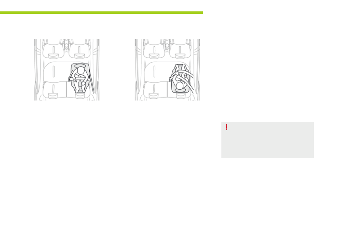
Child seat at the rear
Child safety
Rearward facing
When a rearward facing child seat is installed
on a rear passenger seat, move the vehicle's
front seat forwards and straighten the backrest
so that the rearward facing child seat does not
touch the vehicle's front seat.
Forward facing
When a forward facing child seat is installed
on a rear passenger seat, move the vehicle's
front seat forwards and straighten the backrest
so that the legs of the child in the forward facing
child seat do not touch the vehicle's front seat.
Ensure that the seat belt is correctly
tightened. For child seats with a support
leg, ensure that the support leg is in
stable contact with the floor.
7
73
Page 76
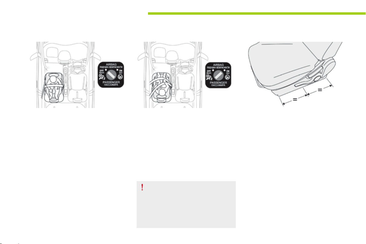
Child safety
Child seat in the front*
74
Rearward facing
When a rearward facing child seat is installed
on the front passenger seat, adjust the seat to
the intermediate longitudinal position, with the
backrest straightened.
The passenger's front airbag must be
deactivated. Otherwise, the child would
risk being seriously injured or killed if the
airbag were to inflate.
Forward facing
When a forward facing child seat is installed on
the front passenger seat, adjust the vehicle's
seat to the intermediate longitudinal position
with seat backrest straightened and leave the
passenger's front airbag activated.
Ensure that the seat belt is correctly
tensioned.
For child seats with a support leg,
ensure that the support leg is in stable
contact with the floor. If necessary,
adjust the passenger seat.
Passenger seat adjusted to the intermediate
longitudinal position.
* Refer to the current legislation in your country
before installing your child on the front seat.
Page 77
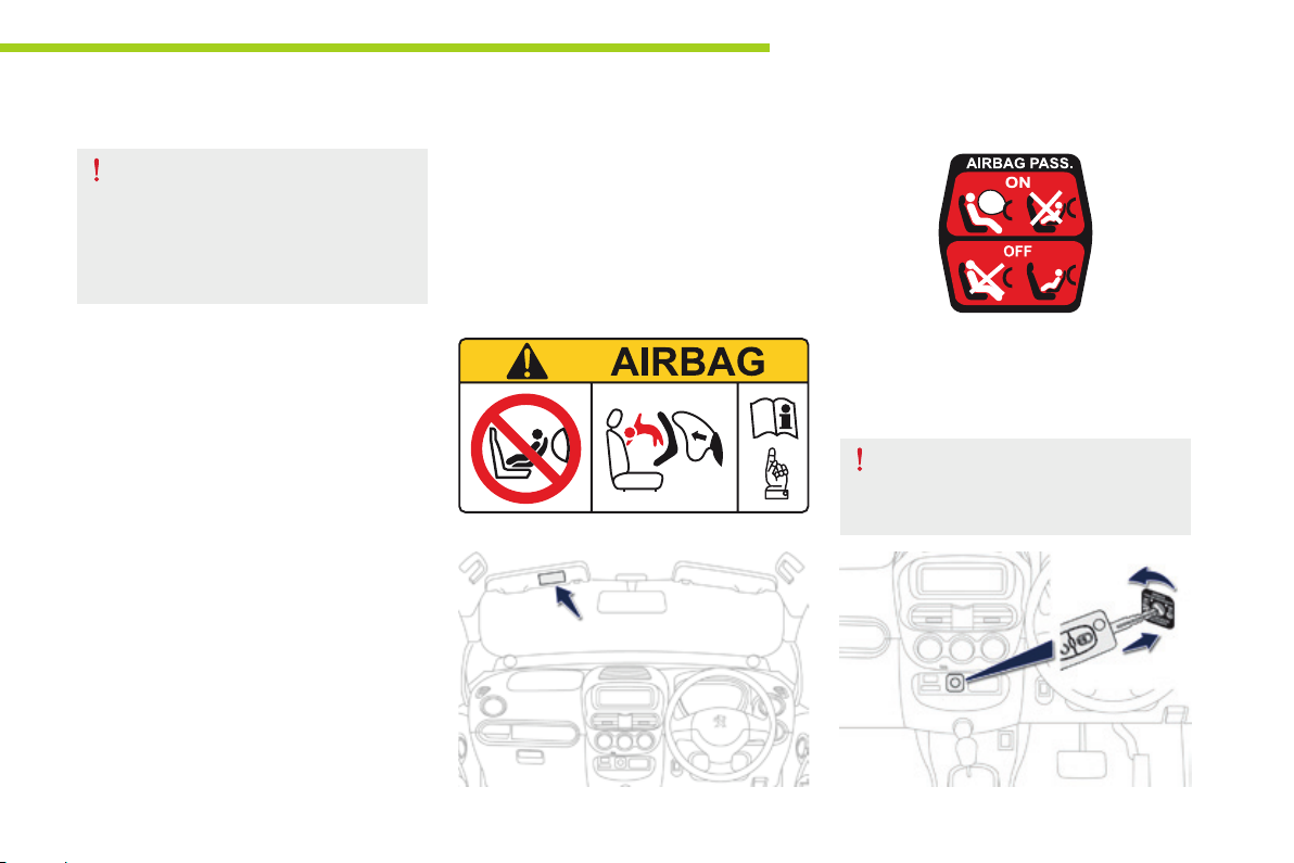
Deactivating the passenger's front airbag
Child safety
Never install a rearward facing child
restraint system on a seat protected by
an active front airbag. This could cause
the death of the child or serious injury.
The warning label present on both sides of the
passenger's sun visor repeats this advice. In
line with current legislation, the following tables
contain this warning in all of the languages
required.
Passenger airbag OFF
This label is located on the middle door pillar,
passenger side.
For information on deactivating the
passenger's front airbag, refer to the
"Airbags" section.
7
75
Page 78
Child safety
AR
НИКОГА НЕ инсталирайте детско столче на седалка с АКТИВИРАНА предна ВЪЗДУШНА ВЪЗГЛАВНИЦ А. Това може да причини
BG
СМЪРТ или СЕРИОЗНО НАРАНЯВАНЕ на детето.
CS
NIKDY neumisťujte dětské zádržné zařízení orientované směrem dozadu na sedadlo chráněné AKTIVOVANÝM čelním AIRBAGEM. Hrozí
nebezpečí SMRTI DÍTĚTE nebo VÁŽNÉHO ZRANĚNÍ.
DA
Brug ALDRIG en bagudvendt barnestol på et sæde, der er beskyttet af en AKTIV AIRBAG. BARNET risikerer at blive ALVORLIGT
KVÆSTET eller DRÆBT.
DE
Montieren Sie auf einem Sitz mit AKTIVIERTEM Front-Airbag NIEMALS einen Kindersitz oder eine Babyschale entgegen der Fahrtrichtung,
das Kind könnte schwere oder sogar tödliche Verletzungen erleiden.
EL
Μη χρησιμοποιείτε ΠΟΤΕ παιδικό κάθισμα με την πλάτη του προς το εμπρός μέρος του αυτοκινήτου, σε μια θέση που προστατεύεται από
ΜΕΤΩΠΙΚΟ αερόσακο που είναι ΕΝΕΡΓΟΣ. Αυτό μπορεί να έχει σαν συνέπεια το ΘΑΝΑΤΟ ή το ΣΟΒΑΡΟ ΤΡΑΥΜΑΤΙΣΜΟ του ΠΑΙΔΙΟΥ
EN
NEVER use a rearward facing child restraint on a seat protected by an ACTIVE AIRBAG in front of it, DEATH or SERIOUS INJURY to the
CHILD can occur
ES
NO INSTALAR NUNCA un sistema de retención para niños de espaldas al sentido de la marcha en un asiento protegido mediante un
AIRBAG frontal ACTIVADO, ya que podría causar lesiones GRAVES o incluso la MUERTE del niño.
ET
Ärge MITTE KUNAGI paigaldage “seljaga sõidusuunas“ lapseistet juhi kõrvalistmele, mille ESITURVAPADI on AKTIVEERITUD. Turvapadja
avanemine võib last TÕSISELT või ELUOHTLIKULT vigastada.
FI
ÄLÄ KOSKAAN aseta lapsen turvaistuinta selkä ajosuuntaan istuimelle, jonka edessä suojana on käyttöön aktivoitu TURVATYYNY. Sen
laukeaminen voi aiheuttaa LAPSEN KUOLEMAN tai VAKAVAN LOUKKAANTUMISEN.
FR
NE JAMAIS installer de système de retenue pour enfants faisant face vers l’arrière sur un siège protégé par un COUSSIN GONFLABLE
frontal ACTIVÉ.
Cela peut provoquer la MORT de l’ENFANT ou le BLESSER GRAVEMENT
HR
NIKADA ne postavljati dječju sjedalicu leđima u smjeru vožnje na sjedalo zaštićeno UKLJUČENIM prednjim ZRAČNIM JASTUKOM. To bi
moglo uzrokovati SMRT ili TEŠKU OZLJEDU djeteta.
HU
SOHA ne használjon menetiránynak háttal beszerelt gyermekülést AKTIVÁLT (BEKAPCSOLT) FRONTLÉGZSÁKK AL védett ülésen. Ez a
gyermek HALÁLÁT vagy SÚLYOS SÉRÜLÉSÉT okozhatja.
IT
NON installare MAI seggiolini per bambini posizionati in senso contrario a quello di marcia su un sedile protetto da un AIRBAG frontale
ATTIVATO. Ciò potrebbe provocare la MORTE o FERITE GRAVI al bambino.
LT
NIEKADA neįrenkite vaiko prilaikymo priemonės su atgal atgręžtu vaiku ant sėdynės, kuri saugoma VEIKIANČIOS priekinės ORO
PAGALVĖS. Išsiskleidus oro pagalvei vaikas gali būti MIRTINAI arba SUNKIAI TRAUMUOTAS.
LV
NEKAD NEuzstādiet uz aizmuguri vērstu bērnu sēdeklīti priekšējā pasažiera sēdvietā, kurā ir AKTIVIZĒTS priekšējais DROŠĪBAS GAISA
SPILVENS.
Tas var izraisīt BĒRNA NĀVI vai radīt NOPIETNUS IEVAINOJUMUS.
76
Page 79

MT
Qatt m’ghandek thalli tifel/tifla marbut f’siggu dahru lejn l-Airbag attiva, ghaliex tista’ tikkawza korriment serju jew anke mewt lit-tifel/tifla
NL
Plaats NOOIT een kinderzitje met de rug in de rijrichting op een zitplaats waarvan de AIRBAG is INGESCHAKELD. Bij het afgaan van de
airbag kan het KIND LEVENSGEVAARLIJK GEWOND RAKEN
NO
Installer ALDRI et barnesete med ryggen mot kjøreretningen i et sete som er beskyttet med en frontal AKTIVERT KOLLISJONSPUTE,
BARNET risikerer å bli DREPT eller HARDT SKADET.
PL
NIGDY nie instalować fotelika dziecięcego w pozycji "tyłem do kierunku jazdy" na siedzeniu wyposażonym w CZOŁOWĄ PODUSZKĘ
POWIETRZNĄ w stanie AKTYWNYM. Może to doprowadzić do ŚMIERCI DZIECKA lub spowodować u niego POWAŻNE OBRAŻENIA
CIAŁA.
PT
NUNCA instale um sistema de retenção para crianças de costas para a estrada num banco protegido por um AIRBAG frontal ACTIVADO.
Esta instalação poderá provocar FERIMENTOS GR AVES ou a MORTE da CRIANÇA.
RO
Nu instalati NICIODATA un sistem de retinere pentru copii, dispus cu spatele in directia de mers, pe un loc din vehicul protejat cu AIRBAG
frontal ACTIVAT. Aceasta ar putea provoca MOARTEA COPILULUI sau RANIREA lui GRAVA.
RU
ВО ВСЕХ СЛУЧАЯХ ЗАПРЕЩАЕТСЯ использовать обращенное назад детское удерживающее устройство на сиденье,
защищенном ФУНКЦИОНИРУЮЩЕЙ ПОДУШКОЙ БЕЗОПАСНОСТИ, установленной перед этим сиденьем.
Это может привести к ГИБЕЛИ РЕБЕНКА или НАНЕСЕНИЮ ЕМУ СЕРЬЕЗНЫХ ТЕЛЕСНЫХ ПОВРЕЖДЕНИЙ
SK
NIKDY neinštalujte detské zádržné zariadenie orientované smerom dozadu na sedadlo chránené AKTIVOVANÝM čelným AIRBAGOM.
Mohlo by dôjsť k SMRTEĽNÉMU alebo VÁŽNEMU PORANENIU DIEŤAŤA.
SL
NIKOLI ne nameščajte otroškega sedeža s hrbtom v smeri vožnje, če je VARNOSTNA BLAZINA pred sprednjim sopotnikovim sedežem
AKTIVIRANA. Takšna namestitev lahko povzroči SMRT OTROKA ali HUDE POŠKODBE.
SR
NIKADA ne koristite dečje sedište koje se okreće unazad na sedištu zaštićenim AKTIVNIM VAZDUŠNIM JASTUKOM ispred njega, jer
mogu nastupiti SMRT ili OZBILJNA POVREDA DETETA.
SV
Passagerarkrockkudden fram MÅSTE vara avaktiverad om en bakåtvänd bilbarnstol installeras på denna plats. Annars riskerar barnet att
DÖDAS eller SKADAS ALLVARLIGT.
TR
KESİNLKLE HAVA YASTIĞI AKTİF olan ön koltuğa yüzü arkaya dönük bir çocuk koltuğu yerleştirmeyiniz. Bu ÇOCUĞUN ÖLMESİNE veya
ÇOK AĞIR YARALANMASINA sebep olabilir.
Child safety
7
77
Page 80
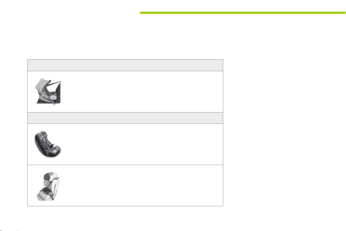
Child safety
Child seats recommended by PEUGEOT
PEUGEOT offers a range of recommended child seats which are secured using a three point
seat belt.
Group 0+: from birth to 13 kg
78
"RÖMER Baby-Safe Plus"
L1
Installed in the rearward facing position.
Groups 2 and 3: from 15 to 36 kg
L4
"KLIPPAN Optima"
From 22 kg (approximately 6 years), the booster is used on its own.
L5
"RÖMER KIDFIX"
Can be fitted to the vehicle's ISOFIX mountings.
The child is restrained by the seat belt.
Page 81
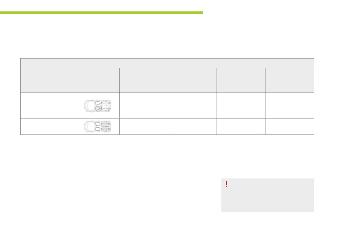
Child safety
Installing child seats using the seat belt
In accordance with European regulations, this table indicates the options for installing child seats secured using a seat belt and universally approved (a)
in accordance with the weight of the child and the seat in the vehicle.
Weight of the child and indicative age
Seat
Front passenger seat (c) (e) L1
Outer rear seats (d) U U U U
(a) Universal child seat: child seat that can be installed in all vehicles using a seat belt.
(b) Group 0: from birth to 10 kg. Shells seats and baby carriers cannot be installed in the front
passenger seat.
(c) Consult the legislation in force in your country before installing your child on this seat.
(d) To install a child seat on a rear seat, rearward or forward facing, move the front seat forward,
then straighten the backrest to allow enough room for the child seat and the child's legs.
(e) When a rearward facing child seat is installed on the front passenger seat, the passenger's
airbag must be deactivated. Otherwise, the child risks being seriously injured or killed if
the airbag is deployed. When a forward facing child seat is installed on the front passenger
seat, the passenger's airbag must remain active.
Under 13 kg
(groups 0 (b) and 0+)
Up to approx 1 year
From 9 to 18 kg
(group 1)
1 to 3 years approx
ISOFIX ROMER Duo
Plus (secured with
the seat belt)
From 15 to 25 kg
(group 2)
3 to 6 years approx
X X
U: Seat suitable for the installation of a
child seat secured using a seat belt and
universally approved, rearward facing and/
or forward facing.
X: Seat not suitable for the installation of a
child seat of the weight group indicated.
Remove and stow the head restraint
before installing a child seat with a
backrest on a passenger seat. Refit the
head restraint once the child seat has
been removed.
From 22 to 36 kg
(group 3)
6 to 10 years approx
7
79
Page 82

Child safety
Advice on child seats
The incorrect installation of a child seat in a
vehicle compromises the child's protection
in the event of an accident.
Check that there is no seat belt or seat belt
buckle under the child seat as this could
destabilise it.
Remember to fasten the seat belts or the
child seat harnesses keeping the slack in
relation to the child's body to a minimum,
even for short journeys.
When installing a child seat using the seat
belt, check that the seat belt is tightened
correctly on the child seat and that it
secures the child seat firmly on the seat
of your vehicle. If your passenger seat is
adjustable, move it forward if necessary.
At the rear seats, always leave sufficient
space between the front seat and:
- a rearward facing child seat,
- the feet of a child seated in a forward
facing child seat.
For this, move the front seat forward and if
necessary straighten its backrest.
For optimum installation of a forward facing
child seat, ensure that the back of the
child seat is as close as possible to the
backrest of the vehicle's seat, or in contact
if possible.
The head restraint must be removed before
installing a child seat with a backrest on
the passenger seat. Ensure that the head
restraint is stowed or attached securely so
that it is not thrown around the vehicle in
the event of sharp braking.
Refit the head restraint as soon as the child
seat is removed.
Children at the front
The legislation on carrying a child on the
front passenger seat is specific to each
country.
Refer to the legislation in force in your
country.
Deactivate the passenger's airbag when
a rearward facing child seat is installed on
the front seat.
Otherwise, the child would risk being
seriously injured or killed if the airbag were
deployed.
Installing a booster seat
The chest part of the seat belt must be
positioned on the child's shoulder without
touching the neck.
Ensure that the lap part of the seat belt
passes correctly over the child's thighs.
PEUGEOT recommends the use of a
booster seat which has a back, fitted with a
seat belt guide at shoulder level.
As a safety precaution, do not leave:
- one or more children alone and
unsupervised in a vehicle,
- a child or an animal in a vehicle which
is exposed to the sun, with the windows
closed,
- the keys within reach of children inside
the vehicle.
To prevent accidental opening of the doors,
use the "Child lock".
Take care not to open the rear windows by
more than one third.
To protect young children from the rays of
the sun, fit side blinds on the rear windows.
80
Page 83
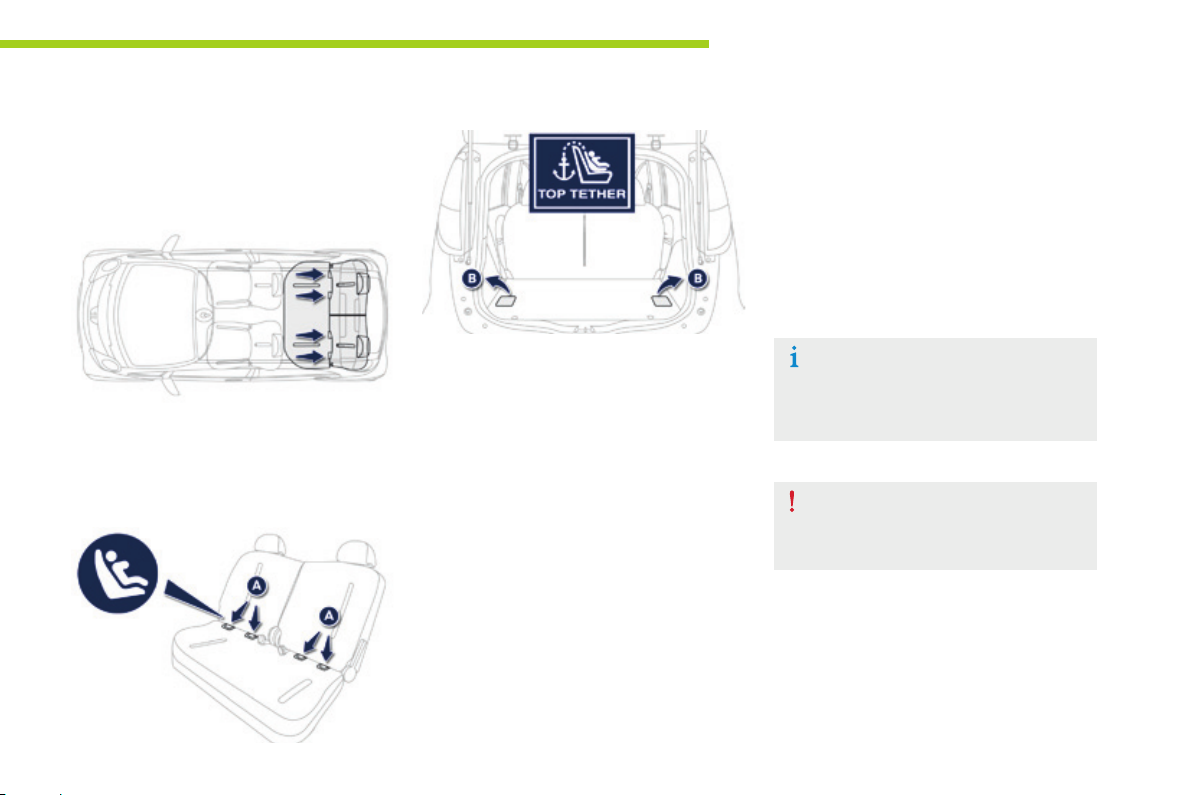
"ISOFIX" mountings
Your vehicle has been approved in accordance
with the latest ISOFIX regulation.
The seats, represented below, are fitted with
regulation ISOFIX mountings:
Child safety
To secure the child seat to the TOP TETHER:
- pass the top strap of the child seat centrally
over the top of the vehicle seat backrest,
- raise the TOP TETHER cover,
- secure the hook on the upper strap to the
ring B,
- tighten the upper strap.
There are three rings for each seat:
- two rings A located in the angle between
the vehicle seat's cushion and backrest,
indicated by a marking
- a ring B for securing the upper strap called
the TOP TETHER, located in the boot.
It is indicated by a marking.
The TOP TETHER is used to secure the
upper strap of child seats that have one. This
arrangement limits the forward tipping of the
child seat in the event of a front impact.
This ISOFIX mounting system provides fast, reliable and safe fitting of the child seat in your vehicle. The ISOFIX child seats are fitted with two latches which are secured on the two rings A. Some seats also have an upper strap which is secured to the ring B.
The incorrect installation of a child seat
in a vehicle compromises the child's
protection in the event of an accident.
Follow precisely the fitting instructions
in the installation guide provided with
the child seat.
For information on the possibilities for installing
ISOFIX child seats in your vehicle, refer to the
summary table.
7
81
Page 84
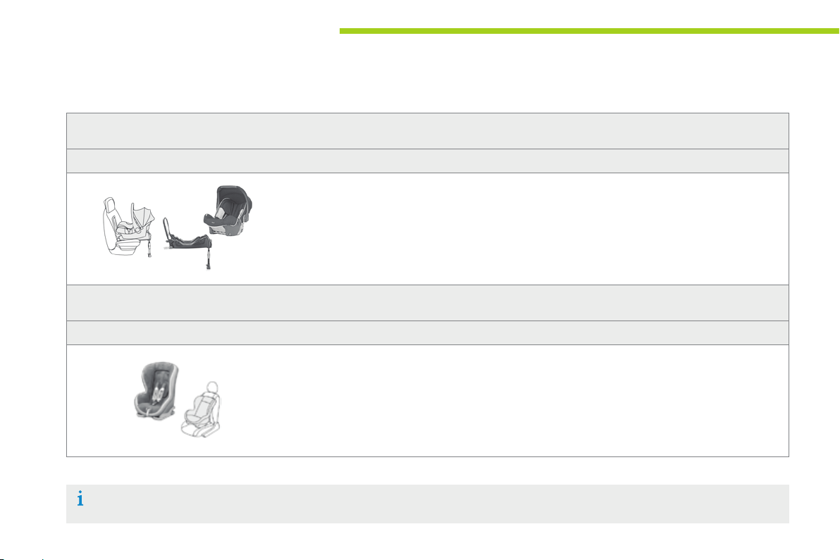
Child safety
ISOFIX child seats recommended by PEUGEOT and approved
for your vehicle
RÖMER BabySafe Plus ISOFIX
(size category E)
Group 0+: up to 13 kg
82
It is installed in the rearward facing position using an ISOFIX base which attaches to the rings A.
The base has a support leg, adjustable for height, that sits on the vehicle floor.
This child seat can also be secured using a child seat. In this case, only the shell is used and is
secured to the vehicle's seat using the three-point seat belt.
RÖMER Duo Plus ISOFIX
(size class B1)
Group 1: from 9 to 18 kg
It is installed only in the forward facing position.
Secured to the rings A, as well as ring B, called the Top Tether, using an upper strap.
Three angles for the shell: sitting, inclined and lying positions.
This child seat can also be used on seats which are not fitted with ISOFIX mountings.
In this case, it must be attached to the vehicle seat using the three point seat belt.
Follow the instructions for fitting the child seat given in their manufacturer's installation guide.
Page 85
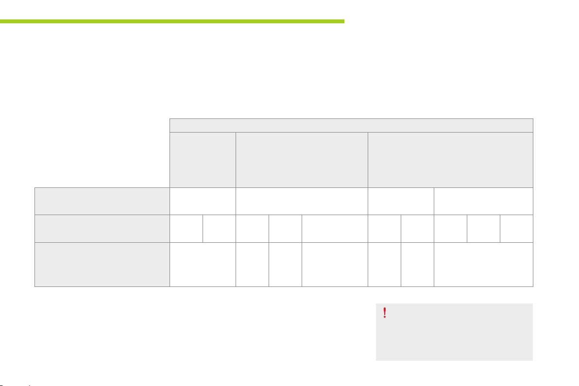
Child safety
Installing ISOFIX child seats
In accordance with European regulations, this table indicates the options for the installation of ISOFIX child seats on the vehicle seats fitted with
ISOFIX mountings.
In the case of the universal and semi-universal ISOFIX child seats, the child seat's ISOFIX size category, determined by a letter between A and G, is
indicated on the child seat next to the ISOFIX logo.
Weight of the child / indicative age
Less than 10 kg
(group 0)
Up to 6 months
approx
Type of ISOFIX child seat Infant car seat* rearward facing rearward facing forward facing
ISOFIX size category F G C D E C D A B B1
Universal and semi-universal
ISOFIX child seats which can be
installed on the outer rear seats
IUF: seat suitable for the installation of an Isofix Universal seat, Forward facing and secured using
the "Top Tether" upper strap.
X: seat which is not suitable for the installation of an ISOFIX seat of the size category indicated.
* Infant car seats and "car cots" cannot be installed on the front passenger seat.
X X X
Less than 10 kg (group 0)
Less than 13 kg (group 0+)
Up to 1 year approx
RÖMER
BabySafe Plus
ISOFIX
From 9 to 18 kg (group 1)
From 1 to 3 years approx
X X IUF
Remove and stow the head restraint
before installing a child seat with a
backrest on a passenger seat. Refit the
head restraint once the child seat has
been removed.
7
83
Page 86
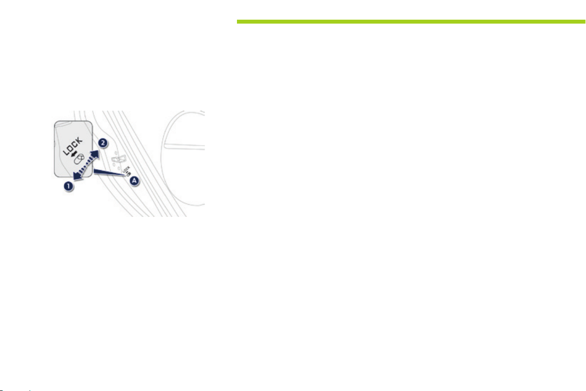
Child safety
Child lock
Mechanical system to prevent opening of the
rear doors using their interior controls.
The control is located on the edge of each
rear door.
Child lock on
F Lower the control A to position 1.
Child lock off
F Raise the control A to position 2.
84
Page 87
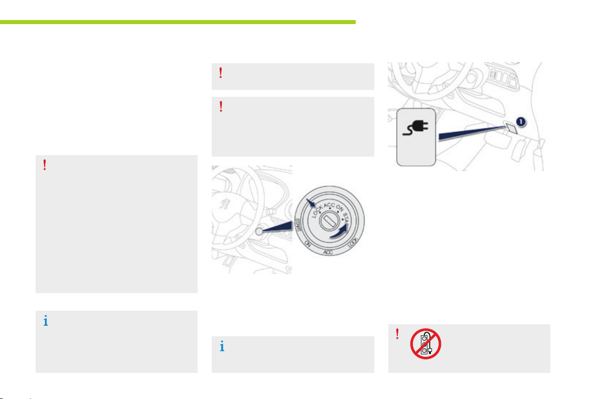
Charging the main battery
There are two types of charging you can use:
normal or fast.
Normal charging should be used in preference;
it is done from a domestic mains power point.
Fast charging is done at a compatible fast
charging station.
Normal charging
Before connecting, check that the
electrical installation you want to use
meets standards* and is compatible
with a current rating of 8A.
In particular, check that the electric
power point is of suitable quality.
There are sockets available that are
specially designed for charging electric
vehicles.
In all cases, it is recommended that
that you first have an initial check
and then regular checks on your
installation by a qualified electrician.
* For example, in France the standard is NF C 15-100.
In most European countries, PEUGEOT
has established a partnership with a
specialist company that can check and
bring your electrical installation up to
standard. For more information, contact
a PEUGEOT dealer.
F Apply the parking brake and put the drive
selector in position P.
F Switch off all electrical consumers and turn
the ignition switch to the "LOCK" position.
You must always use only a genuine
PEUGEOT charging cable.
In the event of damage to or
deterioration of the charging cable or
control unit, do not use it. Contact a
PEUGEOT dealer if in doubt or for a
replacement.
If the ambient temperature is lower
than -25° C, charging may not be
possible.
Practical info rmat ion
F Pull lever 1, located at the bottom of the
dashboard, driver's side, to open the
access flap for the normal charging socket
(right hand side of the vehicle).
F Take the charging cable from the storage
bag provided. This cable has a control unit.
F Connect the charging cable to a compatible
standard power socket. On connecting
the cable, the three POWER, FAULT and
CHARGING lamps all come on temporarily,
then only green POWER lamp stays on.
Do not use an electrical
extension, multi-gang
socket, adaptor or timer.
8
85
Page 88
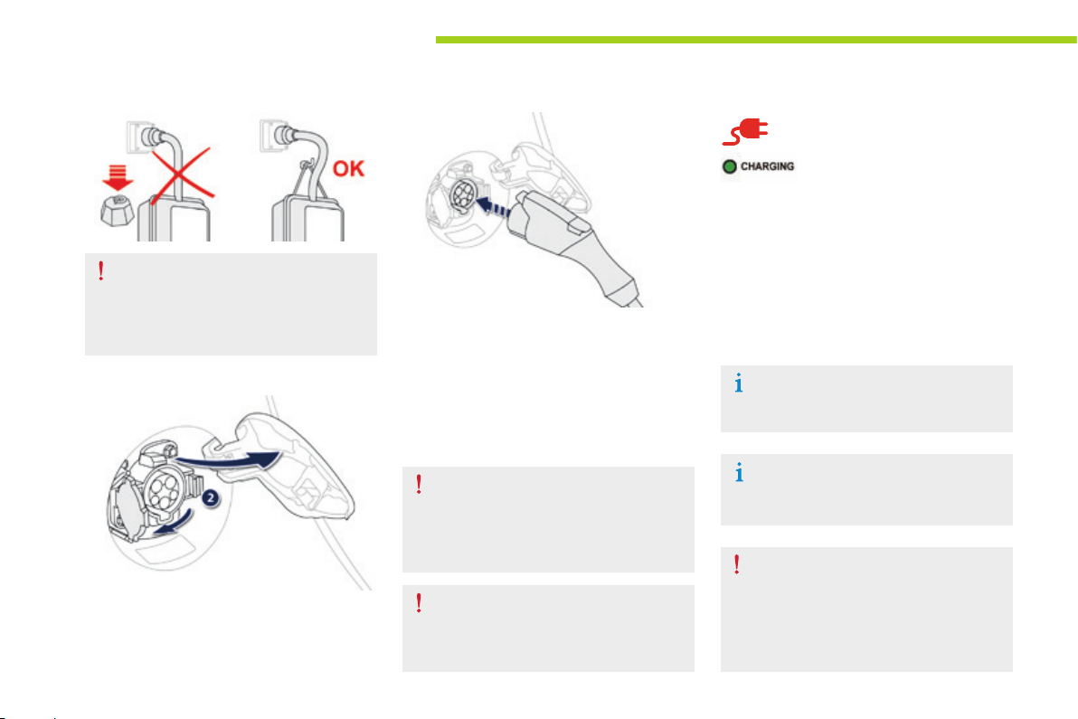
Practical info rmat ion
Use the cord supplied to hook the
control unit, so that it does not weigh
down on the power point (risk of
damage to the charging cable or
electric power point).
F Press the latch 2 to open the socket cover.
F Ensure that there is no foreign object on
the vehicle's socket.
F Remove the protective cover from the
charging cable.
F Insert the charging plug into the socket
without pressing the button, until it clicks
into place.
Do not touch the metal end of the
normal charging socket or of the
charging cable (risk of electrocution
and/or faults).
Never connect or disconnect the cable
or charging plug with wet hands (risk of
electrocution).
F Check that the charging lamp
in the instrument panel and
the green CHARGING lamp in
the control unit are on fixed.
If this is not the case, charging has not
started; repeat the procedure, ensuring that all
connections are correct.
The state of charge indicator for the main
battery is displayed in the instrument panel and
the number of bars illuminated increases as the
battery is charged.
The start of charging may be
accompanied by the noise of a fan
running. This noise is perfectly normal.
The charge may be interrupted at any
time by withdrawing the charging plug.
If exceptionally you have to interrupt the
charge by disconnecting the charging
cable from the power point, it is
essential to first press the Manual Stop
button on the control unit.
86
Page 89
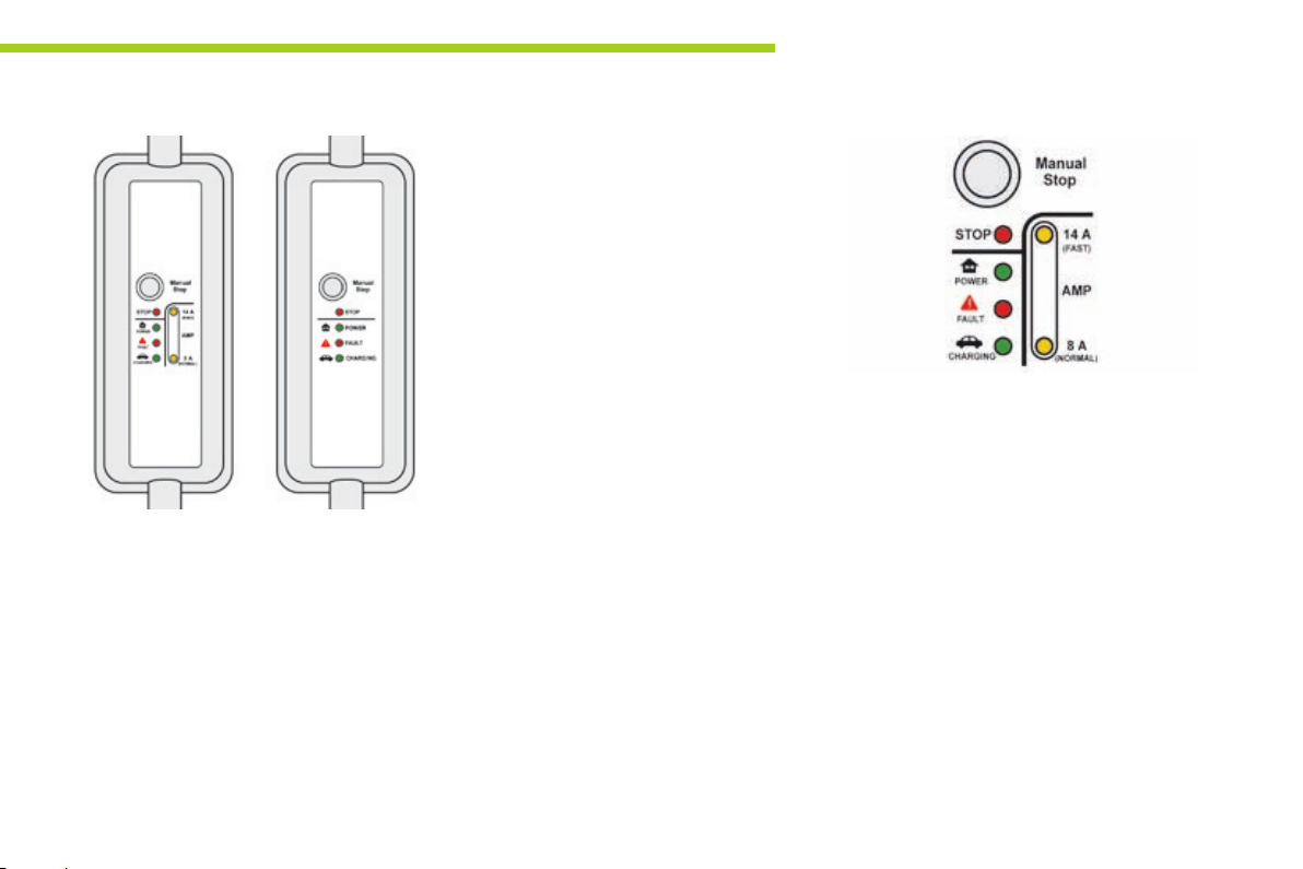
Control unit
There are four indicator lamps:
- STOP: on red.
It indicates that charging has been
interrupted by a press on the Manual Stop
button. This action is essential before
disconnecting the charging cable from the
power point when charging.
- POWER: on green.
It indicates that the electric connection has
been established. If it does not come on,
check that the connections are correct. If
the problem persists, contact a PEUGEOT
dealer or a qualified workshop.
- FAULT: on red.
It indicates the presence of a fault. Check
that the connections are correct. If this
warning lamp does not go off, contact a
PEUGEOT dealer or a qualified workshop.
- CHARGING: on green.
It indicates that charging is in progress.
If it does not come on, check that the
connections are correct. If the problem
persists, contact a PEUGEOT dealer or a
qualified workshop.
Practical info rmat ion
This type of control unit that has a system for
recognising the type of power point (depending
on country). It detects the power rating of your
domestic power point and is able to support
and select the best current rating to ensure
safe charging:
- 14 A (FAST): if your electrical installation
supports it.
- 8 A (NORMAL): if your electrical
installation is standard.
8
87
Page 90
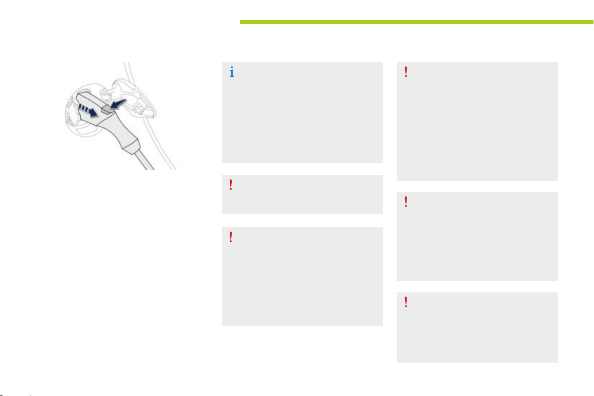
Practical info rmat ion
The charge lamp in the instrument panel going
off and flashing of the green CHARGING lamp
indicate that charging is complete.
F Press the button to remove the charging
plug.
F Refit the protective cover to the charging
cable.
F Close the charging socket cover, then the
flap.
F Disconnect the charging cable from the
power point.
F Stow the charging cable in the bag
provided.
As a safety measure, the motor will
not start when the charging cable is
connected to the vehicle's socket.
Also, any attempt to start the motor
interrupts the charging procedure. It will
then be necessary to disconnect and
reconnect the charging cable plug to
continue charging.
If the 12V ancillaries battery is
discharged, it is not possible to charge
the main battery.
If you wear a pacemaker or other
electrical medical device, you must not
stay inside or near the vehicle during
charging.
It is also important that you take advice
from your doctor on the precautions to
take and observe.
While charging, do not do anything
under the bonnet, even with the ignition
off, as the cooling fan may start at any
time (risk of injury).
You must wait for at least one hour
after the end of the charging procedure
before doing anything under the bonnet,
as some areas can be extremely hot
(risk of burns).
After charging, close the charging
socket cover and flap.
Take care to avoid the ingress of water
or dust to the socket and its cover
or the charging plug (risk of fire or
electrocution).
After removing the charging plug from
the vehicle's socket, do not leave
the cable connected to the electric
power point (risk of short circuit or
electrocution if it is contacted or
immersed in water).
88
Page 91

Practical info rmat ion
In the event of an accident or an impact
to the underbody of the vehicle (contact
with a high kerb, a terminal, street
furniture, ...), the electric circuit or the
main battery may be damaged. Have
your vehicle checked by a PEUGEOT
dealer or a qualified workshop.
Never touch the 300 V components, nor
the orange cables.
In the event of serious damage to
the main battery, never touch liquids
coming from this component.
In the event of contact with your body,
wash abundantly with water and contact
a doctor without delay.
To optimise the service life of the
main battery, recharge it completely
every 15 days.
For a complete charge, follow the
normal charging procedure (domestic
power point) without interruption, until it
stops automatically (charging warning
lamp off in the instrument panel).
In addition, every 3 months, carry out
this complete recharge of the main
battery from a state of charge of
2 bars or less.
Vehicle out of use for a long
period
When your vehicle is going to be out
of use for a long period, charge the
main battery completely every three
months (following the normal charging
procedure).
Before charging, check that the
ancillaries battery is not disconnected
or discharged. If this is the case, refer
to the "ancillaries battery" section for
reconnecting or charging the battery.
8
89
Page 92
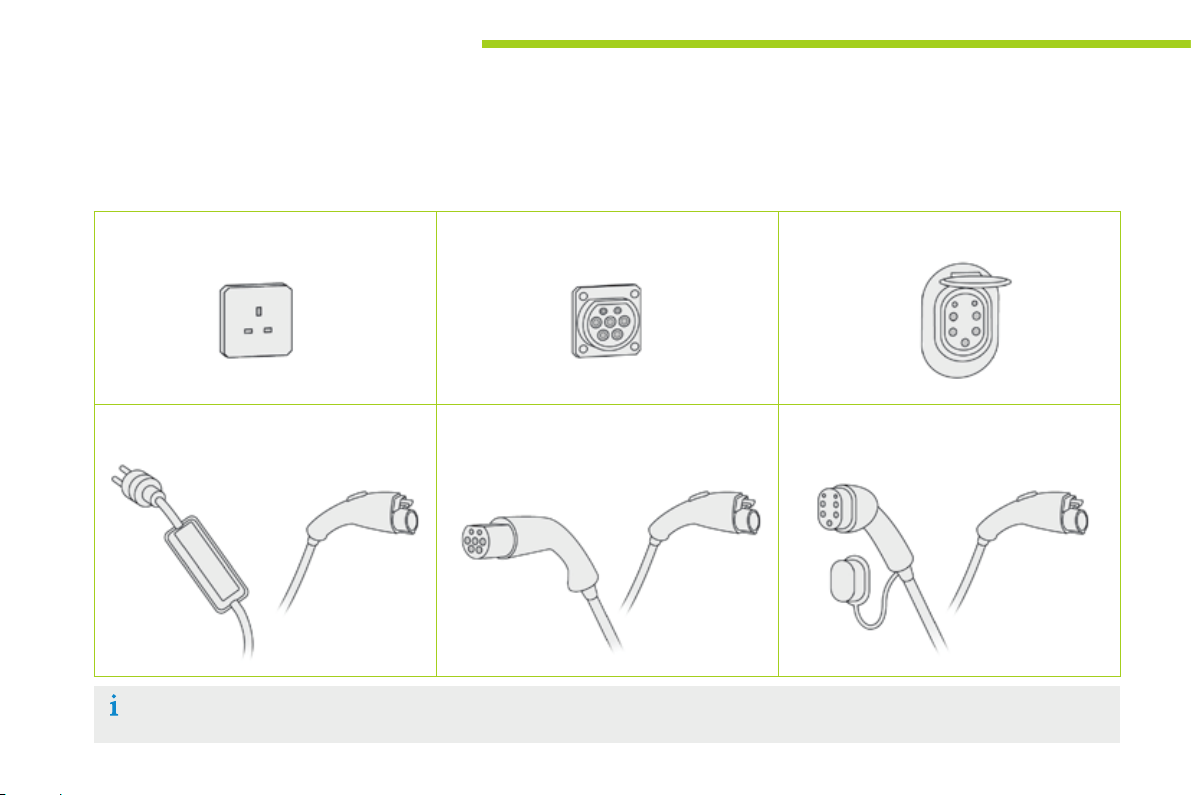
Practical info rmat ion
Using a public charging point for normal charging
Several types of electrical socket may be available for charging your vehicle.
Before starting the charging procedure, use the table below to identify the correct type of socket and use the corresponding charging cable.
Domestic power point "Mode 3 - Type 2" socket "Mode 3 - Type 3" socket
90
"Mode 2" cable (supplied with your vehicle) "Mode 3 - Type 2" cable
(available as an accessory)
Some public charging points include a charging cable.
In this case, use the cable provided.
"Mode 3 - Type 3" cable
(available as an accessory)
Page 93
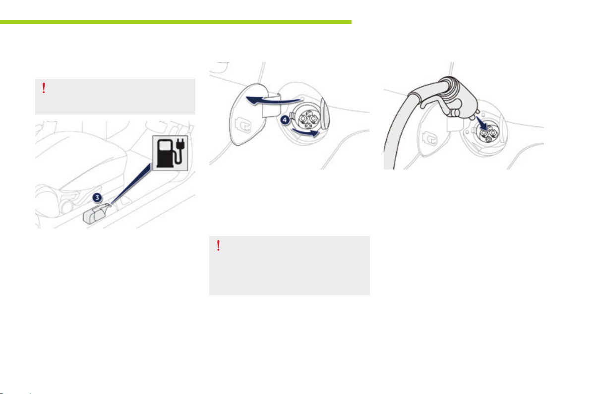
Fast charging*
Check the compatibility of the charging
station and its charging cable with your
vehicle.
Practical info rmat ion
F Apply the parking brake and put the drive
selector in position P.
F Switch off all electrical consumers and turn
the ignition switch to the "LOCK" position.
F Pull lever 3, located alongside the driver's
seat, outer side, to open the access flap for
the fast charging socket (left hand side of
the vehicle).
* Depending on equipment.
F Press latch 4 to open the socket cover.
F Ensure that there is no foreign body on the
vehicle's charging socket.
Do not touch the metal end of the
normal charging socket or of the
charging cable.
Risk of electrocution and/or faults.
F Connect the charging cable of the charging
station to the vehicle following the
instructions on use of the station.
8
91
Page 94

Practical info rmat ion
F
Check that the charging warning lamp
in the instrument panel is on fixed.
If this is not the case, charging has not started;
check the operating instructions for the
charging station.
During the fast charge, the vehicle's air
conditioning may start automatically,
if needed to cool the main battery. It is
therefore perfectly normal to hear the
noise of a fan running from outside the
vehicle and to see a puddle of water
form under the vehicle.
Fast charging stops automatically when
i
the battery is around 80 % charged.
It is possible to attain a level of 100 %
charged by restarting the procedure.
However, the time taken by this
additional charge will be relatively long,
as the charging rate is reduced.
The charging warning lamp in the instrument
panel goes off when charging is complete.
F Disconnect the charging cable following
the instructions for the charging terminal.
F Close the charging socket cover and the flap.
As a safety measure, the motor will
not start when the charging cable is
connected to the vehicle's socket.
Also, any attempt to start the motor
interrupts the charging procedure. It
will then be necessary to disconnect
and reconnect the charging cable
plug to continue charging, following
the instructions for using the charging
station.
After charging, close the charging
socket cover and flap.
Take care to avoid the ingress of water
or dust to the socket and its cover
or the charging plug. Risk of fire or
electrocution.
If the ambient temperature is below 0 °C,
the charging time may be longer.
If the ambient temperature is below -25 °C,
charging may not be possible.
Vehicle out of use for a long
period
When your vehicle is going to be out
of use for a long period, charge the
main battery completely every three
months (following the normal charging
procedure).
Before charging, check that the
ancillaries battery is not disconnected
or discharged. If this is the case, refer
to the "ancillaries battery" section for
reconnecting or charging the battery.
92
Page 95
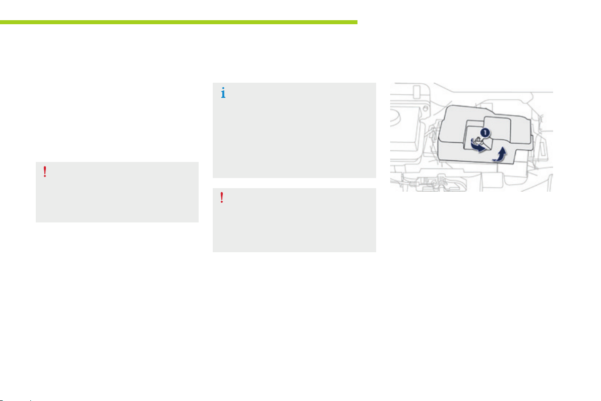
Ancillaries battery
All of the electrical components of your vehicle
(other than the electric motor, the heating and
the air conditioning) are powered by this 12 V
ancillaries battery.
It is located in the front compartment and is
recharged by the main battery, during phases
of operation ("Ready" lamp on in the instrument
panel) and charging.
If the ancillaries battery is discharged,
it will not be possible to start the
motor and the main battery cannot be
charged.
Disconnecting the battery is not
recommended.
However, if the vehicle is not to be
used for a prolonged period of more
than a month, it may be necessary to
disconnect and store it to avoid the
electrolyte freezing.
After prolonged disconnection of the
battery, you must contact a PEUGEOT
dealer or a qualified workshop to have
the electronic control unit reinitialised.
Practical info rmat ion
Access to the batter y
F Open the front bonnet using the interior
release lever , then the e xterior safety catch.
F Secure the bonnet stay.
F Slacken nut 1.
F Remove the battery protective cover for
access to the two terminals.
8
93
Page 96
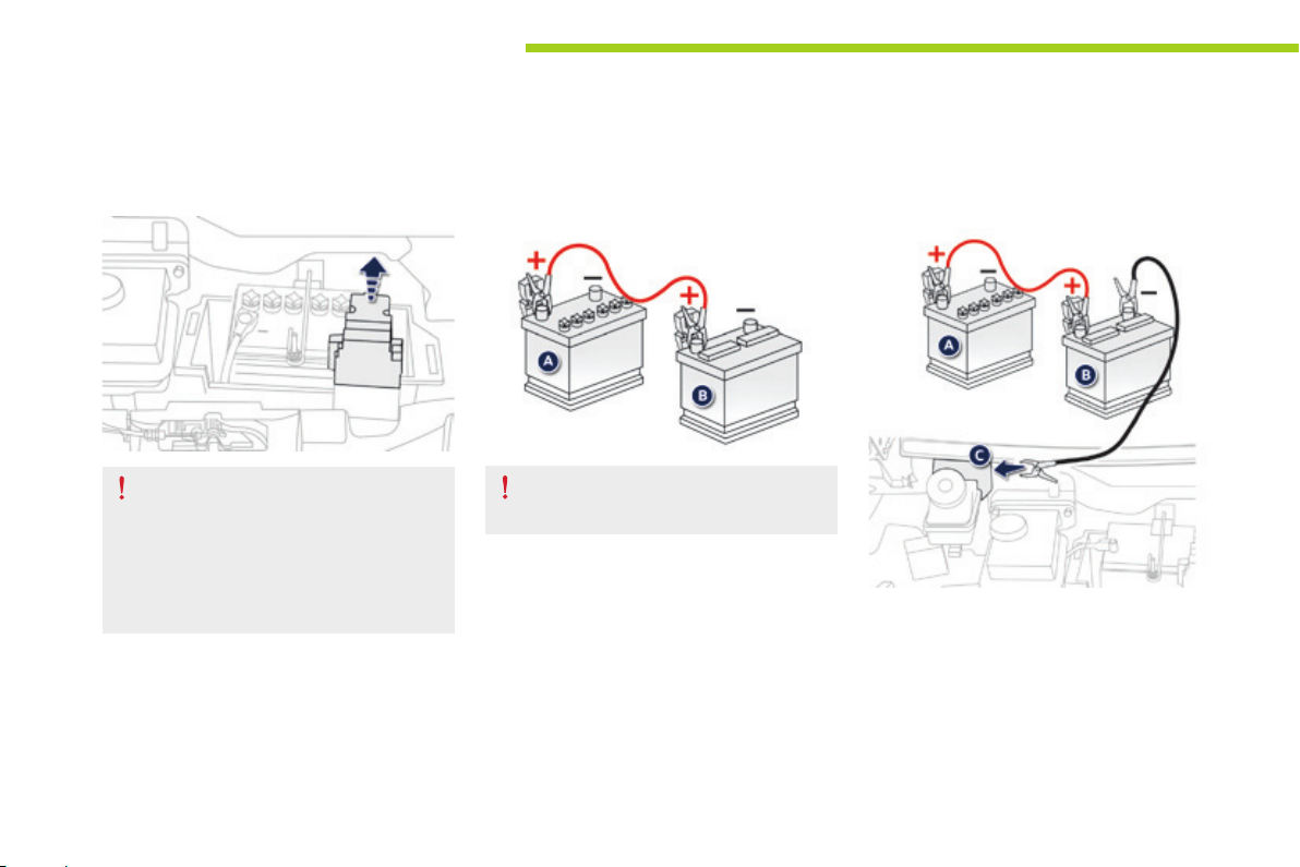
Practical info rmat ion
Starting using a batt er y on
another vehicle
94
Ensure that the electrolyte is not frozen.
Check the electrolyte level and top up
with distilled water if necessary (refer
to the "checking levels" section in this
document).
F Lift the protective cover on the (+) terminal.
Check that the battery on the other
vehicle is a 12 V battery.
F Connect one end of the red cable to the (+)
terminal of your discharged battery A,
then the other end to the (+) terminal of the
battery on the other vehicle B.
F Connect one end of the green or black
cable to the (-) terminal of the battery on
the other vehicle B.
F Connect the other end the green or black
cable to the earth point C of your vehicle.
Page 97
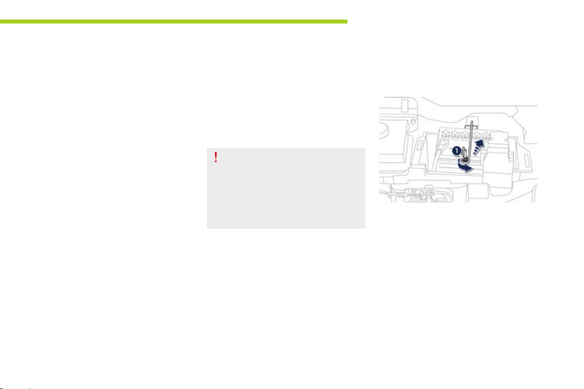
F Start the other vehicle and wait a few
minutes.
F Turn the ignition key on your vehicle, until
the "Ready" lamp comes on.
F Disconnect the cables in the reverse order.
F Refit the battery protective cover and
tighten the fixing screw.
Practical info rmat ion
Charging the battery using
a batter y charger
F Remove the protective cover from the
battery.
Ensure that the electrolyte is not frozen.
Check the electrolyte level and top up
with distilled water if necessary (refer to
the "checking levels" section).
If the "Ready" lamp does not come on, proceed
as follows:
F Leave the cables connected.
F Return the ignition switch on your vehicle
to the "LOCK" position.
F Put the main battery on charge, following
the procedure for normal charging (see the
"charging the main battery" section).
F When the charging warning lamp in
the instrument panel comes on fixed,
disconnect the cables.
F Leave the battery on charge for at least
one hour.
F Turn the ignition key on your vehicle, until
the "Ready" lamp comes on.
If the problem persists, contact a
PEUGEOT dealer or a qualified workshop.
F Slacken nut 1 and lift off the retaining bar.
8
95
Page 98
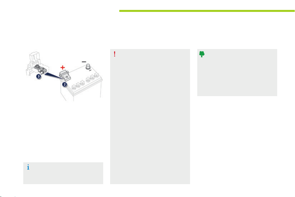
Practical info rmat ion
96
F Disconnect the negative (-) terminal.
F Lift the protective cover on the ( + ) terminal 2.
F Slacken nut 3.
F Disconnect the positive (+) terminal.
F Remove the battery.
F Charge the battery following the
instructions given by the manufacturer of
the battery charger.
F Reconnect the battery starting with
the (+) cable.
Ensure that the battery posts and cable
terminals are clean. If they are covered
with sulphates (whitish or greenish
deposit), disconnect and clean them.
Never charge the battery without
first disconnecting the terminals and
removing it from the vehicle.
Do not disconnect the terminals when
the "Ready" lamp is on, nor when the
vehicle is being charged.
Before disconnecting
You must wait 2 minutes after switching
off the ignition before disconnecting the
battery.
After reconnecting
After reconnecting the battery, switch
on the ignition and wait 1 minute
before starting, to allow initialisation
of the electronic systems. However,
if minor problems persist after doing
this, contact a PEUGEOT dealer or a
qualified workshop.
Remember to enter the radio code
yourself, referring to the relevant
section.
Batteries contain harmful substances
such as sulphuric acid and lead. They
must be disposed of in line with legal
requirements and never put out with
household waste.
Take used batteries to an authorised
collection point.
Page 99
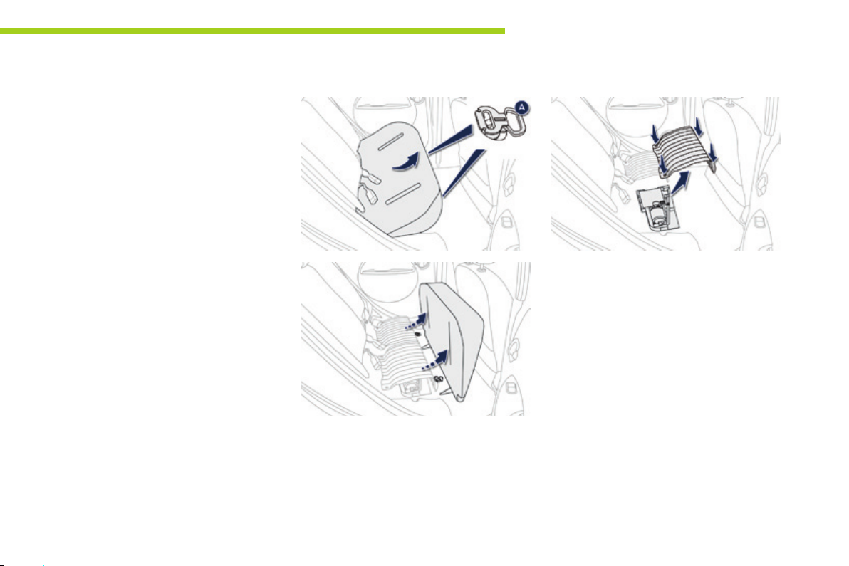
Temporary puncture repair kit
Complete system consisting of a compressor
and a sealant cartridge which permits the
temporary repair of a tyre so that you can
drive to the nearest garage.
It is designed to repair most punctures which
could affect the tyre, located on the tyre tread
or shoulder.
Practical info rmat ion
Access to the kit
This kit is installed in the storage box, under the
rear seat, right hand side.
You must therefore remove the rear seat
cushion for access to the kit.
Removing the metal cover
F Remove the four "butterfly" screws.
F Remove the metal cover.
You now have access to the repair kit.
8
Removing the rear seat cushion
F Pull the controls A forwards to release the
rear seat cushion.
F Lift the front of the cushion and tip it
upwards to remove it.
97
Page 100

Practical info rmat ion
Retting the rear seat cushion
F Put the metal cover back into place.
F Refit the four "butterfly" screws.
F Insert the metal hooks into the seat
backrest.
F Fold the seat cushion down until it locks in
place.
When refitting the cushion, take care
not to trap the seat belt buckles.
Composition of the kit
1. 12 V compressor with integral pressure
gauge, to measure and adjust the tyre
pressure.
2. Sealant cartridge for the temporary repair
of a tyre.
3. Injection pipe.
4. Suction pipe, to remove the sealant product
if necessary.
5. Sachet containing a replacement valve
core, a tool for removing/refitting the valve
core and a speed restriction sticker.
The speed restriction sticker must be
affixed to the vehicle's steering wheel to
remind you that a wheel is in temporary
use.
Do not exceed a speed of 50 mph
(80 km/h ) when driving with a tyre repaired
using this type of kit.
98
 Loading...