

Page 1

Models covered
Saloon and Estate models with 4-cylinder SOHC and DOHC petrol engines,
including Mi-16 and special/limited editions;
1.4 (1360 cc), 1.6 (1580 cc), 1.8 (1761 cc), 1.9 (1905 cc) and 2.0 (1998 cc)
For Diesel engine models, see OWM 3198
Does not cover four-wheel-drive models
© Haynes Publishing 1996
A book in the Haynes Service and Repair Manual Series
All rights reserved. No part of this book may be reproduced or transmitted
in any form or by any means, electronic or mechanical, including
photocopying, recording or by any information storage or retrieval system,
without permission in writing from the copyright holder.
ISBN 1 85960 174 X
British Library Cataloguing in Publication Data
A catalogue record for this book is available from the British Library.
Printed by J H Haynes & Co. Ltd, Sparkford, Nr Yeovil,
Somerset BA22 7JJ
Haynes Publishing
Sparkford, Nr Yeovil, Somerset BA22 7JJ, England
Haynes North America, Inc
861 Lawrence Drive, Newbury Park, California 91320, USA
Editions Haynes S.A.
147/149, rue Saint Honoré, 75001 PARIS, France
Peugeot 405 (petrol)
Service and Repair Manual
Steve Rendle and A K Legg LAE MIMI
(1559-336)
Page 2

LIVING WITH YOUR PEUGEOT 405
Introduction to the Peugeot 405 Page 0•4
Safety first! Page 0•5
Roadside Repairs
If your car won’t start Page 0•6
Jump starting Page 0•7
Wheel changing Page 0•8
Identifying leaks Page 0•9
Towing Page 0•9
Weekly Checks
Introduction Page 0•10
Underbonnet check points Page 0•10
Engine oil level Page 0•12
Coolant level Page 0•12
Brake fluid level Page 0•13
Power steering fluid level Page 0•13
Tyre condition and pressure Page 0•14
Screen washer fluid level Page 0•15
Wiper blades Page 0•15
Battery Page 0•16
Bulbs and fuses Page 0•16
Lubricants, fluids and tyre pressures Page 0•17
MAINTENANCE
Routine Maintenance and Servicing
Peugeot 405 petrol models Page 1•1
Maintenance schedule - models up to 1993 Page 1•3
Maintenance schedule - models from 1994 Page 1•4
Maintenance procedures Page 1•8
Contents
Page 3

REPAIRS AND OVERHAUL
Engine and Associated Systems
TU petrol engine in-car repair procedures Page 2A•1
XU petrol engine in-car repair procedures Page 2B•1
Engine removal and overhaul procedures Page 2C•1
Cooling, heating and ventilation systems Page 3•1
Fuel/exhaust systems - carburettor models Page 4A•1
Fuel/exhaust systems - single-point fuel injection models Page 4B•1
Fuel/exhaust systems - multi-point fuel injection models Page 4C•1
Emission control systems Page 4D•1
Starting and charging systems Page 5A•1
Ignition system Page 5B•1
Transmission
Clutch Page 6•1
Manual transmission Page 7A•1
Automatic transmission Page 7B•1
Driveshafts Page 8•1
Brakes and Suspension
Braking system Page 9•1
Suspension and steering Page 10•1
Body equipment
Bodywork and fittings Page 11•1
Body electrical systems Page 12•1
Wiring Diagrams Page 12•22
REFERENCE
Dimensions and weights Page REF•1
Conversion factors Page REF•2
Buying spare parts and vehicle identification Page REF•3
General repair procedures Page REF•4
Jacking and vehicle support Page REF•5
Radio/cassette unit anti-theft system - precaution Page REF•5
Tools and working facilities Page REF•6
MOT test checks Page REF•8
Fault finding Page REF•12
Glossary of technical terms Page REF•20
Index Page REF•25
Contents
Page 4
The Peugeot 405 model range was introduced into the UK in
January 1988 in Saloon form only.
Available with 1.6, 1.8, 1.9 and 2.0 engines, all models have front-
wheel-drive with all round independent suspension.
Automatic transmission models were introduced in April 1988.
In July 1988 came the sporty Mi 16 version with its 1.9 litre double
overhead cam, 16-valve engine, uprated gearbox, suspension and an
ABS braking system to match its power.
Estate car versions were introduced in October 1988.
From 1991, engines equipped with catalytic converters were
progressively introduced, to meet the more stringent exhaust gas
emission regulations.
Since its introduction, the 405 range has continually been
developed. All models have a high trim level, which is very
comprehensive in the upper model range.
For the home mechanic, the Peugeot 405 is a straightforward
vehicle to maintain and repair since design features have been
incorporated to reduce the actual cost of ownership to a minimum, and
most of the items requiring frequent attention are easily accessible.
Your Peugeot 405 Manual
The aim of this manual is to help you get the best value from your
vehicle. It can do so in several ways. It can help you decide what work
must be done (even should you choose to get it done by a garage),
provide information on routine maintenance and servicing, and give a
logical course of action and diagnosis when random faults occur.
However, it is hoped that you will use the manual by tackling the work
yourself. On simpler jobs, it may even be quicker than booking the car
into a garage and going there twice, to leave and collect it. Perhaps
most important, a lot of money can be saved by avoiding the costs a
garage must charge to cover its labour and overheads.
The manual has drawings and descriptions to show the function of
the various components, so that their layout can be understood. Then
the tasks are described and photographed in a clear step-by-step
sequence.
0•4 Introduction
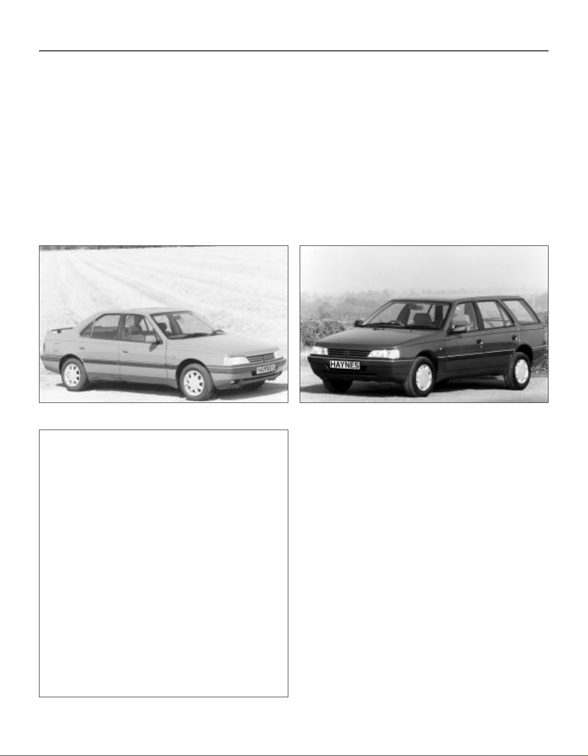
Peugeot 405 SRi Saloon Peugeot 405 GL Estate
Acknowledgements
Thanks are due to Champion Spark Plug who supplied the
illustrations showing spark plug conditions. Certain other illustrations
are the copyright of the Peugeot Talbot Motor Company Limited, and
are used with their permission. Special thanks to Gliddons of Taunton
who provided several of the project vehicles used in the origination of
this manual. Thanks are also due to Sykes-Pickavant Limited, who
provided some of the workshop tools, and to all those people at
Sparkford who helped in the production of this manual.
We take great pride in the accuracy of information given in this
manual, but vehicle manufacturers make alterations and design
changes during the production run of a particular vehicle of which
they do not inform us. No liability can be accepted by the authors
or publishers for loss, damage or injury caused by any errors in, or
omissions from, the information given.
Project vehicles
The vehicles used in the preparation of this manual, and which
appear in many of the photographic sequences, were a Peugeot 405
GL Saloon, a Peugeot 405 GTX Estate, a Peugeot 405 GR Saloon, and
a Peugeot GTX Saloon.
The Peugeot 405 Team
Haynes manuals are produced by dedicated and
enthusiastic people working in close co-operation. The
team responsible for the creation of this book included:
Authors Steve Rendle
Andy Legg
Sub-editor Carole Turk
Editor & Page Make-up Bob Jex
Workshop manager Paul Buckland
Photo Scans John Martin
Paul Tanswell
Cover illustration & Line Art Roger Healing
Wiring diagrams Matthew Marke
We hope the book will help you to get the maximum
enjoyment from your car. By carrying out routine
maintenance as described you will ensure your car’s
reliability and preserve its resale value.
Page 5
Safety First! 0•5
Working on your car can be dangerous.
This page shows just some of the potential
risks and hazards, with the aim of creating a
safety-conscious attitude.
General hazards
Scalding
• Don’t remove the radiator or expansion
tank cap while the engine is hot.
• Engine oil, automatic transmission fluid or
power steering fluid may also be dangerously
hot if the engine has recently been running.
Burning
• Beware of burns from the exhaust system
and from any part of the engine. Brake discs
and drums can also be extremely hot
immediately after use.
Crushing
• When working under or near
a raised vehicle,
always
supplement the
jack with axle
stands, or use
drive-on
ramps.
Never
venture
under a car which
is only supported by a jack.
• Take care if loosening or tightening hightorque nuts when the vehicle is on stands.
Initial loosening and final tightening should
be done with the wheels on the ground.
Fire
• Fuel is highly flammable; fuel vapour is
explosive.
• Don’t let fuel spill onto a hot engine.
• Do not smoke or allow naked lights
(including pilot lights) anywhere near a
vehicle being worked on. Also beware of
creating sparks
(electrically or by use of tools).
• Fuel vapour is heavier than air, so don’t
work on the fuel system with the vehicle over
an inspection pit.
• Another cause of fire is an electrical
overload or short-circuit. Take care when
repairing or modifying the vehicle wiring.
• Keep a fire extinguisher handy, of a type
suitable for use on fuel and electrical fires.
Electric shock
• Ignition HT
voltage can be
dangerous,
especially to
people with heart
problems or a
pacemaker. Don’t
work on or near the
ignition system with
the engine running or
the ignition switched on.
• Mains voltage is also dangerous. Make
sure that any mains-operated equipment is
correctly earthed. Mains power points should
be protected by a residual current device
(RCD) circuit breaker.
Fume or gas intoxication
• Exhaust fumes are
poisonous; they often
contain carbon
monoxide, which is
rapidly fatal if inhaled.
Never run the
engine in a
confined space
such as a garage
with the doors shut.
• Fuel vapour is also
poisonous, as are the vapours from some
cleaning solvents and paint thinners.
Poisonous or irritant substances
• Avoid skin contact with battery acid and
with any fuel, fluid or lubricant, especially
antifreeze, brake hydraulic fluid and Diesel
fuel. Don’t syphon them by mouth. If such a
substance is swallowed or gets into the eyes,
seek medical advice.
• Prolonged contact with used engine oil can
cause skin cancer. Wear gloves or use a
barrier cream if necessary. Change out of oilsoaked clothes and do not keep oily rags in
your pocket.
• Air conditioning refrigerant forms a
poisonous gas if exposed to a naked flame
(including a cigarette). It can also cause skin
burns on contact.
Asbestos
• Asbestos dust can cause cancer if inhaled
or swallowed. Asbestos may be found in
gaskets and in brake and clutch linings.
When dealing with such components it is
safest to assume that they contain asbestos.
Special hazards
Hydrofluoric acid
• This extremely corrosive acid is formed
when certain types of synthetic rubber, found
in some O-rings, oil seals, fuel hoses etc, are
exposed to temperatures above 4000C. The
rubber changes into a charred or sticky
substance containing the acid. Once formed,
the acid remains dangerous for years. If it
gets onto the skin, it may be necessary to
amputate the limb concerned.
• When dealing with a vehicle which has
suffered a fire, or with components salvaged
from such a vehicle, wear protective gloves
and discard them after use.
The battery
• Batteries contain sulphuric acid, which
attacks clothing, eyes and skin. Take care
when topping-up or carrying the battery.
• The hydrogen gas given off by the battery
is highly explosive. Never cause a spark or
allow a naked light nearby. Be careful when
connecting and disconnecting battery
chargers or jump leads.
Air bags
• Air bags can cause injury if they go off
accidentally. Take care when removing the
steering wheel and/or facia. Special storage
instructions may apply.
Diesel injection equipment
• Diesel injection pumps supply fuel at very
high pressure. Take care when working on
the fuel injectors and fuel pipes.
Warning: Never expose the hands,
face or any other part of the body
to injector spray; the fuel can
penetrate the skin with potentially fatal
results.
Remember...
DO
• Do use eye protection when using power
tools, and when working under the vehicle.
• Do wear gloves or use barrier cream to
protect your hands when necessary.
• Do get someone to check periodically
that all is well when working alone on the
vehicle.
• Do keep loose clothing and long hair well
out of the way of moving mechanical parts.
• Do remove rings, wristwatch etc, before
working on the vehicle – especially the
electrical system.
• Do ensure that any lifting or jacking
equipment has a safe working load rating
adequate for the job.
A few tips
DON’T
• Don’t attempt to lift a heavy component
which may be beyond your capability – get
assistance.
• Don’t rush to finish a job, or take
unverified short cuts.
• Don’t use ill-fitting tools which may slip
and cause injury.
• Don’t leave tools or parts lying around
where someone can trip over them. Mop
up oil and fuel spills at once.
• Don’t allow children or pets to play in or
near a vehicle being worked on.
Page 6
0•6 Roadside Repairs
The following pages are intended to help in dealing with
common roadside emergencies and breakdowns. You will find
more detailed fault finding information at the back of the
manual, and repair information in the main chapters.
If your car won’t start
and the starter motor
doesn’t turn
M If it’s a model with automatic transmission, make sure the
selector is in ‘P’ or ‘N’.
M Open the bonnet and make sure that the battery terminals
are clean and tight.
M Switch on the headlights and try to start the engine. If the
headlights go very dim when you’re trying to start, the
battery is probably flat. Get out of trouble by jump starting
(see next page) using a friend’s car.
If your car won’t start
even though the starter
motor turns as normal
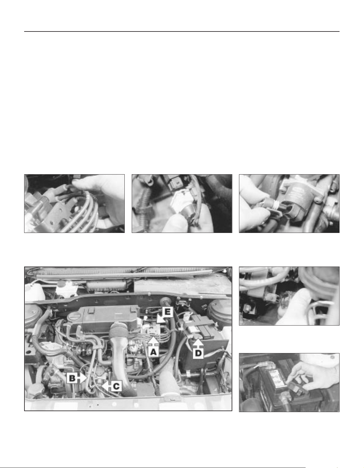
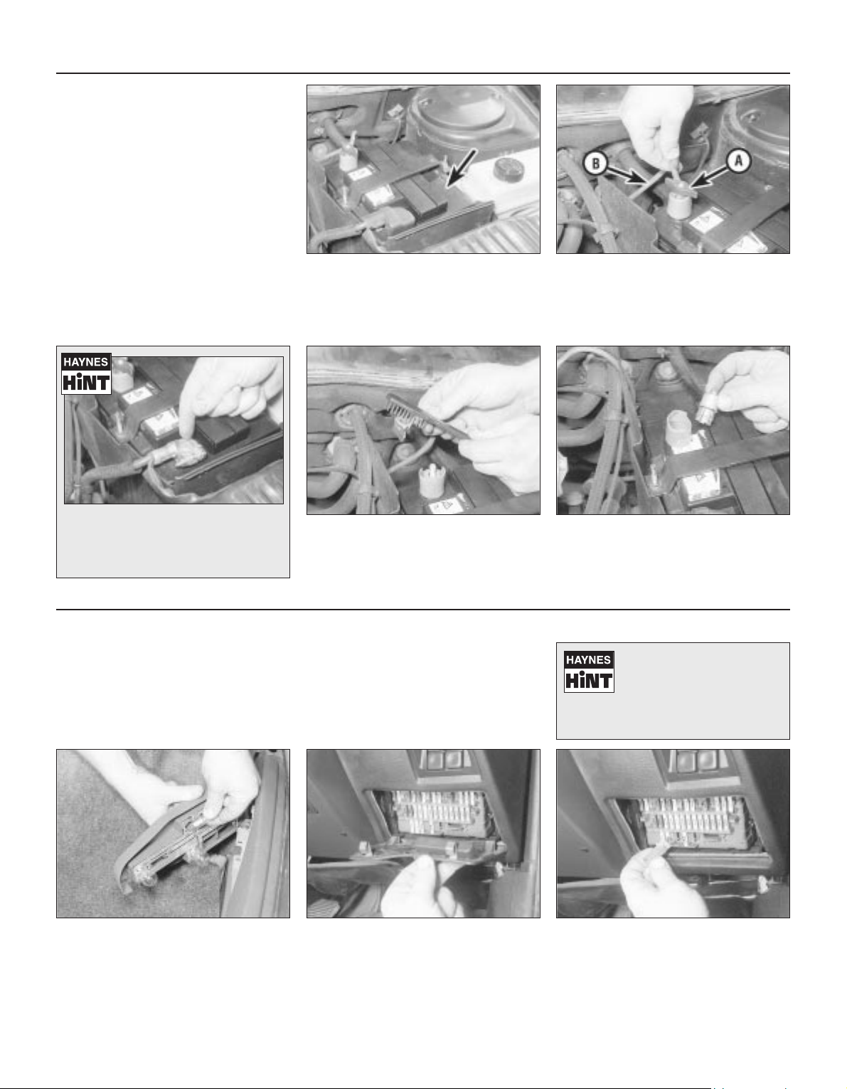
M Is there fuel in the tank?
M Is there moisture on electrical components under the
bonnet? Switch off the ignition, then wipe off any obvious
dampness with a dry cloth. Spray a water-repellent aerosol
product (WD-40 or equivalent) on ignition and fuel system
electrical connectors like those shown in the photos.
Pay special attention to the ignition coil wiring connector
and HT leads. (Note that Diesel engines don’t normally
suffer from damp.)
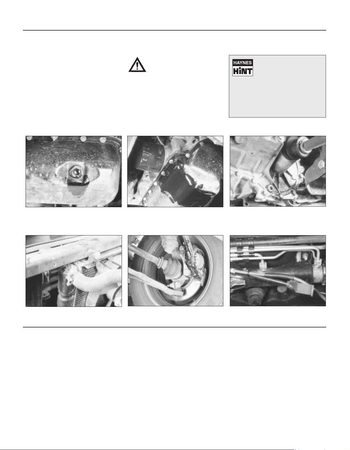
Check that the spark plug HT leads
(where applicable) are securely
connected by pushing them home.
A
The throttle potentiometer wiring plug
may cause problems if not connected
securely.
B
Check the idle speed stepper motor
wiring plug for security.
C
Check the security and condition of the
battery connections.
D
Check that the ignition coil wiring plug is
secure, and spray with water-dispersant
if necessary.
E
Check that electrical connections are secure (with the ignition switched off) and spray them
with a water dispersant spray like WD40 if you suspect a problem due to damp
Page 7
Roadside Repairs 0•7
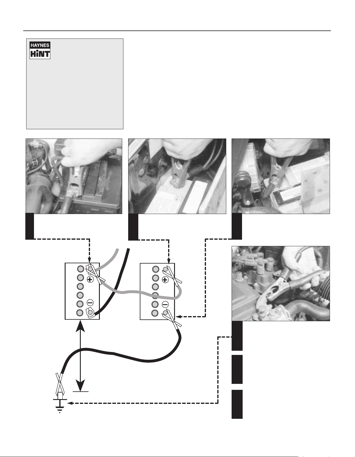
When jump-starting a car using a
booster battery, observe the following
precautions:
4 Before connecting the booster
battery, make sure that the ignition is
switched off.
4 Ensure that all electrical equipment
(lights, heater, wipers, etc) is
switched off.
4 Make sure that the booster battery is
the same voltage as the discharged
one in the vehicle.
4 If the battery is being jump-started
from the battery in another vehicle,
the two vehcles MUST NOT TOUCH
each other.
4 Make sure that the transmission is in
neutral (or PARK, in the case of
automatic transmission).
Jump starting will get you out
of trouble, but you must correct
whatever made the battery go
flat in the first place. There are
three possibilities:
1
The battery has been drained by
repeated attempts to start, or by
leaving the lights on.
2
The charging system is not working
properly (alternator drivebelt slack
or broken, alternator wiring fault or
alternator itself faulty).
3
The battery itself is at fault
(electrolyte low, or battery worn out).
Connect one end of the red jump lead to
the positive (+) terminal of the flat
battery
Connect the other end of the red lead to
the positive (+) terminal of the booster
battery.
Connect one end of the black jump lead
to the negative (-) terminal of the
booster battery
Connect the other end of the black
jump lead to a bolt or bracket on the
engine block, well away from the
battery, on the vehicle to be started.
1
2
3
4
Make sure that the jump leads will not
come into contact with the fan, drivebelts or other moving parts of the
engine.
5
Start the engine using the booster
battery, then with the engine running at
idle speed, disconnect the jump leads in
the reverse order of connection.
6
Jump starting
Page 8
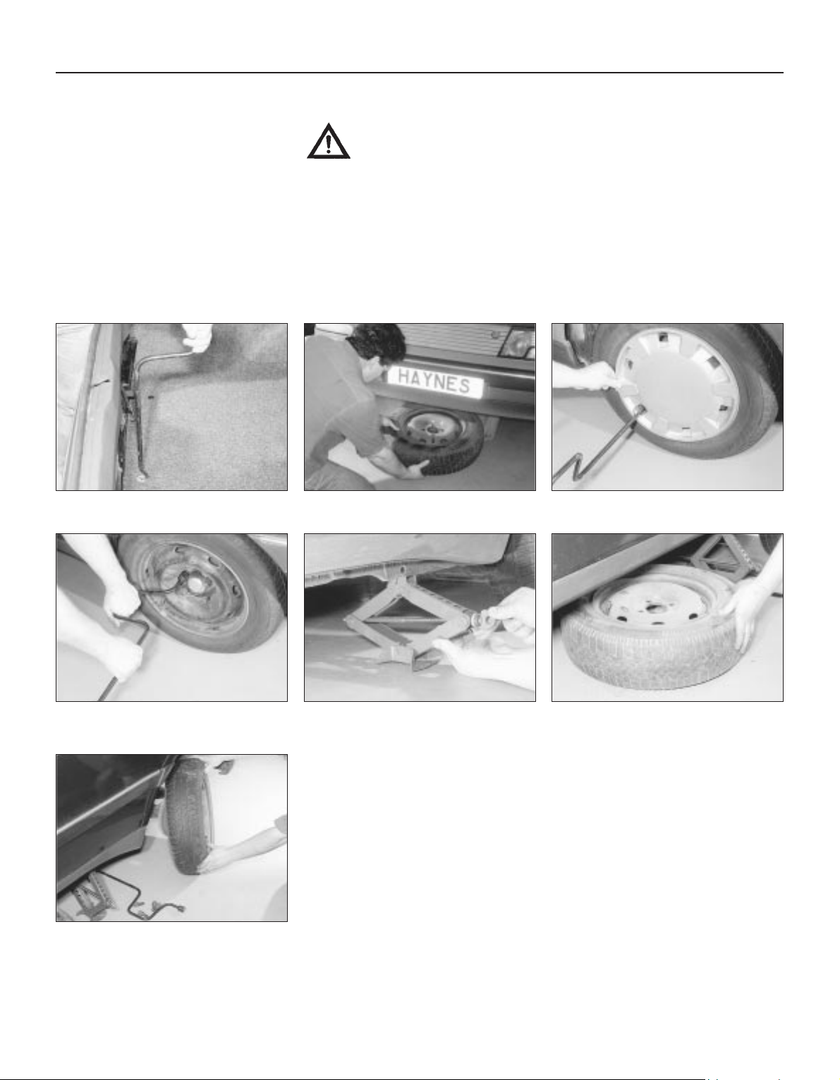
In the boot, use the wheel brace to
loosen the spare wheel cradle bolt.
0•8 Roadside Repairs
Wheel changing
Some of the details shown here will vary
according to model. For instance, the location
of the spare wheel and jack is not the same
on all cars. However, the basic principles
apply to all vehicles.
M When a puncture occurs, stop as soon
as it is safe to do so.
M Park on firm level ground, if possible,
and well out of the way of other traffic.
M Use hazard warning lights if necessary.
M If you have one, use a warning triangle to
alert other drivers of your presence.
M Apply the handbrake and engage first or
reverse gear.
M Chock the wheel diagonally opposite the
one being removed – a couple of large
stones will do for this.
M If the ground is soft, use a flat piece of
wood to spread the load under the foot
of the jack.
Changing the wheel
Preparation
Warning: Do not change a wheel in a situation where you risk being hit by
other traffic. On busy roads, try to stop in a lay-by or a gateway. Be wary of
passing traffic while changing the wheel – it is easy to become distracted by
the job in hand.
Finally...
M Remove the wheel chocks.
M Stow the jack and tools in the correct locations in the car.
M Make sure that the spare wheel cradle is properly secured, or it could drop onto the road
while driving.
M
Check the tyre pressure on the wheel just fitted. If it is low, or if you don’t have a pressure
gauge with you, drive slowly to the nearest garage and inflate the tyre to the right pressure.
M Have the damaged tyre or wheel repaired as soon as possible.
Before raising the car, loosen the wheel
bolts slightly using the wheelbrace.
Locate the jack head in the jacking point
and use the brace to raise the car until
the wheel is clear of the ground.
Temporarily place the spare wheel under
the sill as a precaution should the jack
topple.
Use the wheel brace to remove the wheel
trim.
Remove the spare wheel from the cradle.
1
2
3
4
5
6
Remove the bolts and remove the wheel.
Fit the spare wheel and hand-tighten the
bolts. Lower the car, then tighten the
wheel bolts firmly. Have the bolts tightened to
the correct torque at the earliest opportunity.
7
Page 9
Roadside Repairs 0•9
When all else fails, you may find yourself
having to get a tow home – or of course you
may be helping somebody else. Long-distance
recovery should only be done by a garage or
breakdown service. For shorter distances, DIY
towing using another car is easy enough, but
observe the following points:
M Use a proper tow-rope – they are not
expensive. The vehicle being towed must
display an ‘ON TOW’ sign in its rear window.
M Always turn the ignition key to the ‘on’
position when the vehicle is being towed, so
that the steering lock is released, and that the
direction indicator and brake lights will work.
M Only attach the tow-rope to the towing
eyes provided.
M Before being towed, release the handbrake
and select neutral on the transmission.
M Note that greater-than-usual pedal
pressure will be required to operate the
brakes, since the vacuum servo unit is only
operational with the engine running.
M On models with power steering, greaterthan-usual steering effort will also be required.
M The driver of the car being towed must
keep the tow-rope taut at all times to avoid
snatching.
M Make sure that both drivers know the route
before setting off.
M Only drive at moderate speeds and keep
the distance towed to a minimum. Drive
smoothly and allow plenty of time for slowing
down at junctions.
M On models with automatic transmission,
special precautions apply. If in doubt, do not
tow, or transmission damage may result.
Towing
Puddles on the garage floor or drive, or
obvious wetness under the bonnet or
underneath the car, suggest a leak that needs
investigating. It can sometimes be difficult to
decide where the leak is coming from,
especially if the engine bay is very dirty
already. Leaking oil or fluid can also be blown
rearwards by the passage of air under the car,
giving a false impression of where the
problem lies.
Warning: Most automotive oils
and fluids are poisonous. Wash
them off skin, and change out of
contaminated clothing, without
delay.
Identifying leaks
The smell of a fluid leaking
from the car may provide a
clue to what’s leaking. Some
fluids are distinctively
coloured. It may help to clean the car
carefully and to park it over some clean
paper overnight as an aid to locating the
source of the leak.
Remember that some leaks may only
occur while the engine is running.
Sump oil Gearbox oil
Brake fluid Power steering fluid
Oil from filter
Antifreeze
Engine oil may leak from the drain plug... ...or from the base of the oil filter.
Leaking antifreeze often leaves a crystalline
deposit like this.
Gearbox oil can leak from the seals at the
inboard ends of the driveshafts.
A leak occurring at a wheel is almost
certainly brake fluid.
Power steering fluid may leak from the pipe
connectors on the steering rack.
Page 10
0•10 Weekly Checks
There are some very simple checks which
need only take a few minutes to carry out, but
which could save you a lot of inconvenience
and expense.
These "Weekly checks" require no great skill
or special tools, and the small amount of time
they take to perform could prove to be very
well spent.
M Keeping an eye on tyre condition and
pressures, will not only help to stop them
wearing out prematurely, but could also save
your life.
M
Many breakdowns are caused by electrical
problems. Battery-related faults are particularly
common, and a quick check on a regular basis
will often prevent the majority of
these.
M If your car develops a brake fluid leak, the
first time you might know about it is when
your brakes don't work properly. Checking
the level regularly will give advance warning of
this kind of problem.
M If the oil or coolant levels run low, the cost
of repairing any engine damage will be far
greater than fixing the leak, for example.
Introduction
§
1.6 litre
carburettor
A
Engine oil level dipstick
B
Engine oil filler cap
C
Coolant filler cap
D
Brake fluid reservoir
E
Screen washer fluid reservoir
Underbonnet check points
§
1.6 litre
fuel injection
A
Engine oil level dipstick
B
Engine oil filler cap
C
Coolant filler cap
D
Brake fluid reservoir
E
Power steering fluid reservoir
F
Screen washer fluid reservoir
Page 11
Weekly Checks 0•11
§
1.9 litre
A
Engine oil level dipstick
B
Engine oil filler cap
C
Coolant filler cap
D
Brake fluid reservoir
E
Power steering fluid reservoir
F
Screen washer fluid reservoir
§
2.0 litre
A
Engine oil level dipstick
B
Engine oil filler cap
C
Coolant filler cap
D
Brake fluid reservoir
E
Power steering fluid reservoir
F
Screen washer fluid reservoir
Page 12
0•12 Weekly Checks
Warning: DO NOT attempt to
remove the expansion tank
pressure cap when the engine
is hot, as there is a very great
risk of scalding. Do not leave
open containers of coolant
about, as it is poisonous.
Car Care
l With a sealed-type cooling system,
adding coolant should not be necessary on a
regular basis. If frequent topping-up is
required, it is likely there is a leak. Check the
radiator, all hoses and joint faces for signs of
staining or wetness, and rectify as necessary.
l It is important that antifreeze is used in
the cooling system all year round, not just
during the winter months. Don’t top-up with
water alone, as the antifreeze will become
too diluted.
Coolant level
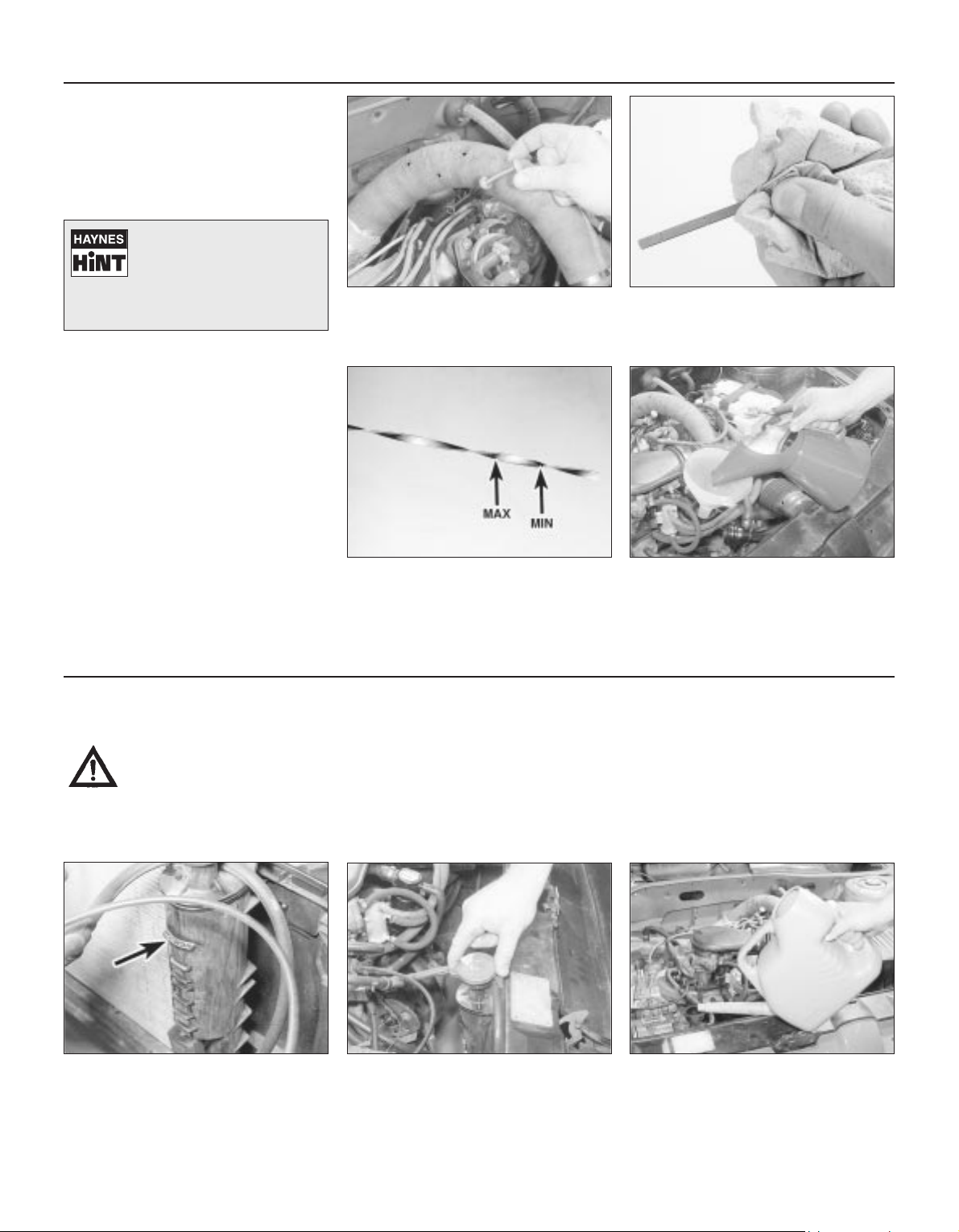
The coolant level varies with engine
temperature. When cold, the coolant
level should be on the “MAXI” mark
(arrowed). When the engine is hot, the level
may rise slightly above the “MAXI” mark.
If topping up is necessary, wait until the
engine is cold. Unscrew the expansion
tank cap to the first stop, to release any
pressure present in the system. Push the cap
down, turn to the second stop, and remove it.
Add a mixture of water and antifreeze
through the expansion tank filler neck,
until the coolant level is up to the “MAXI”
level mark. Refit the cap, turning it clockwise
as far as it will go to secure.
1
23
Engine oil level
Before you start
4 Make sure your car is on level ground.
4 Check the oil level before the car is driven,
or at least 5 minutes after the engine has been
switched off.
The correct oil
Modern engines place great demands on their
oil. It is very important that the correct oil for
your car is used (See “Lubricants, fluids and
tyre pressures”).
Car Care
l If you have to add oil frequently, you
should check whether you have any oil leaks.
Place some clean paper under the car
overnight, and check for stains in the morning.
If there are no leaks, the engine may be
burning oil (see “Fault Finding”).
l Always maintain the level between the
upper and lower dipstick marks (see photo 3).
If the level is too low severe engine damage
may occur. Oil seal failure may result if the
engine is overfilled by adding too much oil.
If the oil is checked
immediately after driving the
vehicle, some of the oil will
remain in the upper engine
components, resulting in an inaccurate
reading on the dipstick!
The dipstick top is often brightly coloured
for easy identification (see “Underbonnet
check points” on pages 0•10 and 0•11
for exact location). Withdraw the dipstick.
Using a clean rag or paper towel remove
all oil from the dipstick. Insert the clean
dipstick into the tube as far as it will go,
then withdraw it again.
Note the oil level on the end of the
dipstick, which should be between the
upper ("MAX") mark and lower ("MIN")
mark. Approximately 1.0 litre of oil will raise
the level from the lower mark to the upper
mark.
Oil is added through the filler cap.
Unscrew the cap and top-up the level; a
funnel may help to reduce spillage. Add
the oil slowly, checking the level on the dipstick
often. Don’t overfill (see “Car Care” left).
12
34
Page 13
Weekly Checks 0•13
Brake fluid level
Warning: Brake fluid can harm
your eyes and damage painted
surfaces, so use extreme
caution when handling and
pouring it.
Warning: Do not use fluid that has been
standing open for some time, as it absorbs
moisture from the air, which can cause a
dangerous loss of braking effectiveness.
Before you start:
4 Park the vehicle on level ground.
4 On models with ABS (anti-lock brakes),
switch the ignition off and pump the brake
pedal at least 20 times or until the pedal
feels hard. Open the bonnet. Switch on
the ignition: the hydraulic unit pump will
be heard running. Wait until the pump
stops, then switch off the ignition.
Safety First!
l If the reservoir requires repeated toppingup this is an indication of a fluid leak
somewhere in the system, which should be
investigated immediately.
l If a leak is suspected, the car should not
be driven until the braking system has been
checked. Never take any risks where brakes
are concerned.
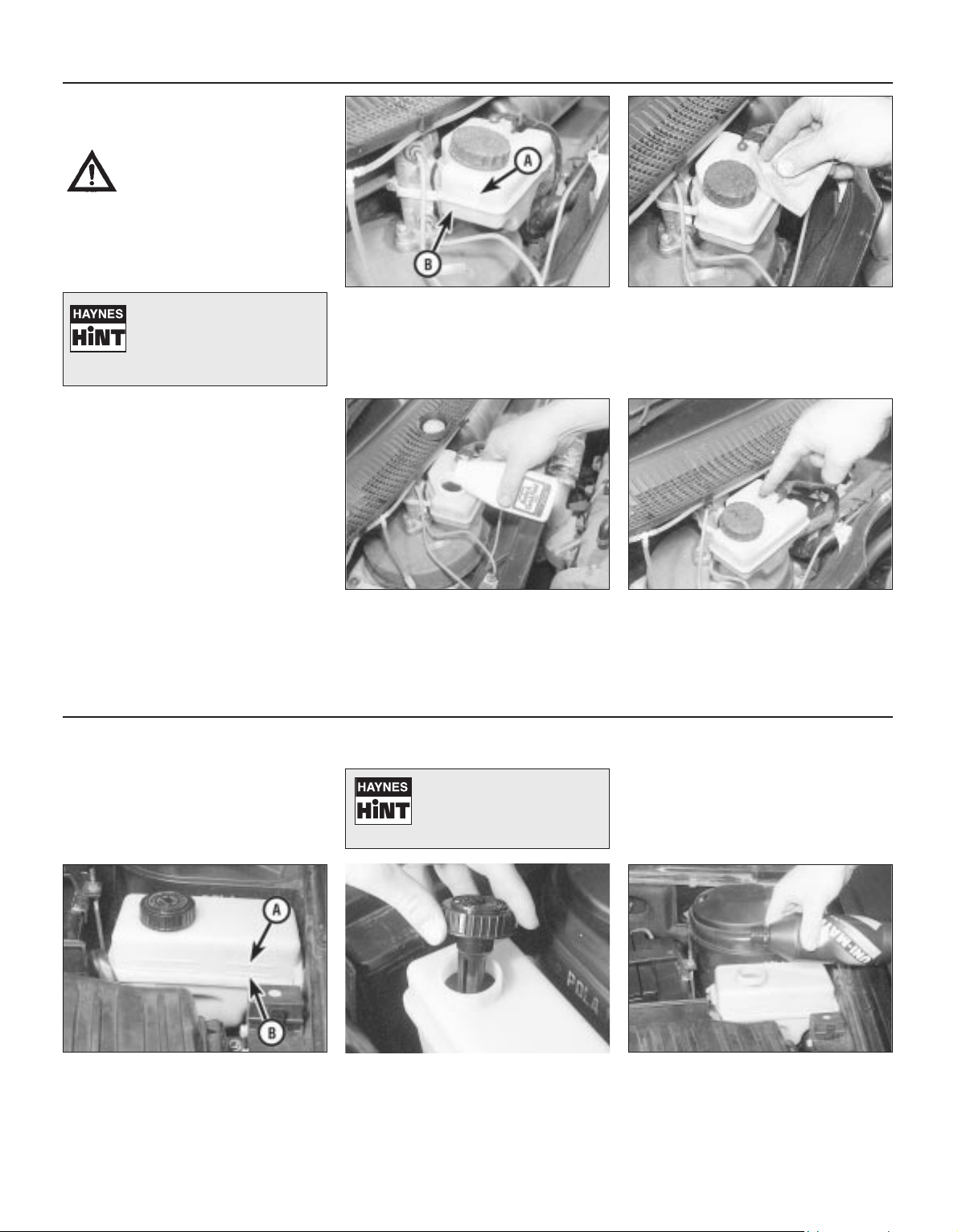
The fluid level in the reservoir
will drop slightly as the brake
pads wear down, but the
fluid level must never be
allowed to drop below the “MIN” mark.
The “MAX” (A) and “DANGER” (B) marks
are indicated on the side of the reservoir,
which is located in the scuttle at the rear
driver’s side of the engine compartment.
The fluid level must be kept between these
two marks.
1
If topping-up is necessary, first wipe the
area around the filler cap with a clean rag
before removing the cap. Check the fluid
already in the reservoir - the system should be
drained and refilled if dirt is seen in the fluid
(see Chapter 9 for details).
2
Carefully add fluid, avoiding spilling it on
surrounding paintwork. Use only the
specified hydraulic fluid; mixing different
types of fluid can cause damage to the
system and/or a loss of braking effectiveness.
After filling to the correct level, refit the cap
securely. Wipe off any spilt fluid.
3
Check the operation of the low fluid level
warning light. Chock the roadwheels,
release the handbrake, and switch on the
ignition. Ask an assistant to press the button on
top of the reservoir. The brake fluid level/
handbrake warning light should come on. Apply
the handbrake and switch off the ignition
4
Power steering fluid level
Before you start:
4 Park the car on level ground.
4 Set the steering wheel straight-ahead.
4 The engine should be turned off.
Safety First!
l The need for frequent topping-up
indicates a leak, which should be investigated
immediately.
For the check to be
accurate, the steering must
not be turned once the
engine has been stopped.
The fluid level is visible through the
translucent material of the reservoir, and
should be between the maximum (A) and
minimum (B) level lines marked on the side of
the reservoir.
1
If topping-up is necessary, and before
removing the cap, wipe the area so that
dirt does not enter the reservoir. Unscrew
the cap, allowing the fluid to drain from the
bottom of the cap as it is removed.
2
Top-up to the “MAX” mark, using the
specified type of fluid. Take great care
not to allow dirt to enter the reservoir,
and do not overfill the reservoir. When the
level is correct, refit the cap.
3
Page 14
0•14 Weekly Checks
Tyre condition and pressure
It is very important that tyres are in good
condition, and at the correct pressure - having
a tyre failure at any speed is highly dangerous.
Tyre wear is influenced by driving style - harsh
braking and acceleration, or fast cornering,
will all produce more rapid tyre wear. As a
general rule, the front tyres wear out faster
than the rears. Interchanging the tyres from
front to rear ("rotating" the tyres) may result in
more even wear. However, if this is
completely effective, you may have the
expense of replacing all four tyres at once!
Remove any nails or stones embedded in the
tread before they penetrate the tyre to cause
deflation. If removal of a nail does reveal that
the tyre has been punctured, refit the nail so
that its point of penetration is marked. Then
immediately change the wheel, and have the
tyre repaired by a tyre dealer.
Regularly check the tyres for damage in the
form of cuts or bulges, especially in the
sidewalls. Periodically remove the wheels,
and clean any dirt or mud from the inside and
outside surfaces. Examine the wheel rims for
signs of rusting, corrosion or other damage.
Light alloy wheels are easily damaged by
"kerbing" whilst parking; steel wheels may
also become dented or buckled. A new wheel
is very often the only way to overcome severe
damage.
New tyres should be balanced when they are
fitted, but it may become necessary to rebalance them as they wear, or if the balance
weights fitted to the wheel rim should fall off.
Unbalanced tyres will wear more quickly, as
will the steering and suspension components.
Wheel imbalance is normally signified by
vibration, particularly at a certain speed
(typically around 50 mph). If this vibration is
felt only through the steering, then it is likely
that just the front wheels need balancing. If,
however, the vibration is felt through the
whole car, the rear wheels could be out of
balance. Wheel balancing should be carried
out by a tyre dealer or garage.
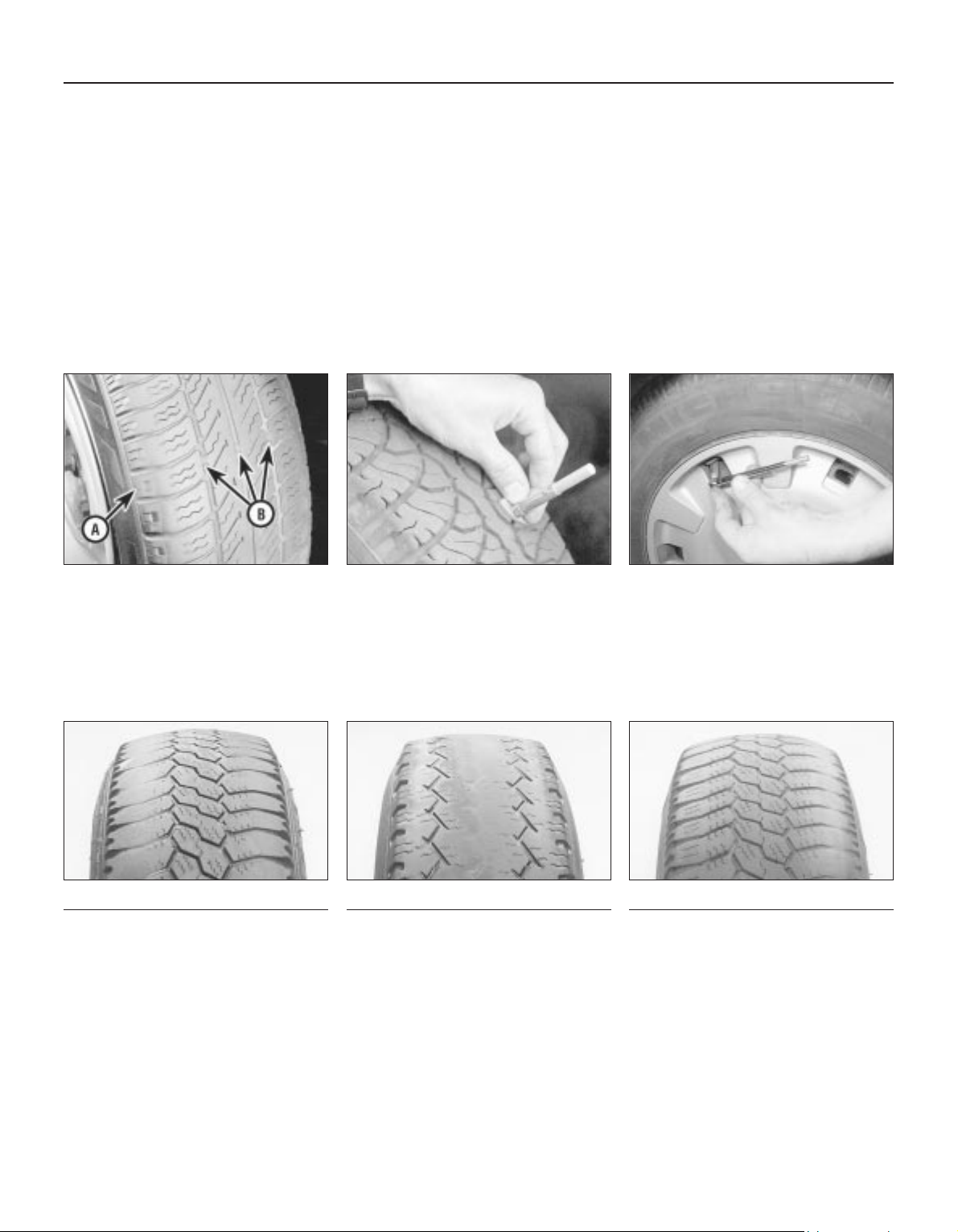
Tread Depth - visual check
The original tyres have tread wear safety
bands (B), which will appear when the tread
depth reaches approximately 1.6 mm. The
band positions are indicated by a triangular
mark on the tyre sidewall (A).
1
Tread Depth - manual check
Alternatively, tread wear can be
monitored with a simple, inexpensive device
known as a tread depth indicator gauge.
2
Tyre Pressure Check
Check the tyre pressures regularly with
the tyres cold. Do not adjust the tyre
pressures immediately after the vehicle has
been used, or an inaccurate setting will result.
3
Tyre tread wear patterns
Shoulder Wear
Underinflation (wear on both sides)
Under-inflation will cause overheating of the
tyre, because the tyre will flex too much, and
the tread will not sit correctly on the road
surface. This will cause a loss of grip and
excessive wear, not to mention the danger of
sudden tyre failure due to heat build-up.
Check and adjust pressures
Incorrect wheel camber (wear on one side)
Repair or renew suspension parts
Hard cornering
Reduce speed!
Centre Wear
Overinflation
Over-inflation will cause rapid wear of the
centre part of the tyre tread, coupled with
reduced grip, harsher ride, and the danger of
shock damage occurring in the tyre casing.
Check and adjust pressures
If you sometimes have to inflate your car’s
tyres to the higher pressures specified for
maximum load or sustained high speed, don’t
forget to reduce the pressures to normal
afterwards.
Uneven Wear
Front tyres may wear unevenly as a result of
wheel misalignment. Most tyre dealers and
garages can check and adjust the wheel
alignment (or "tracking") for a modest charge.
Incorrect camber or castor
Repair or renew suspension parts
Malfunctioning suspension
Repair or renew suspension parts
Unbalanced wheel
Balance tyres
Incorrect toe setting
Adjust front wheel alignment
Note: The feathered edge of the tread which
typifies toe wear is best checked by feel.
Page 15
Weekly Checks 0•15
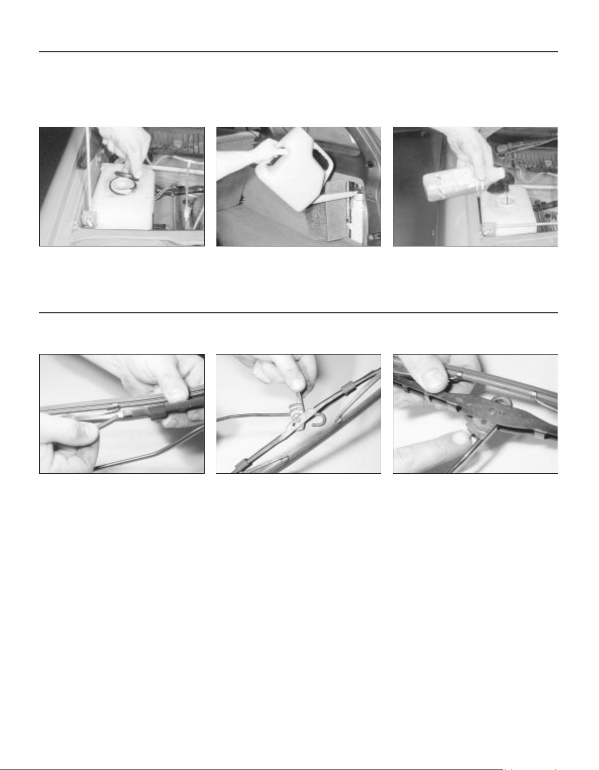
Wiper blades
Check the condition of the wiper blades;
if they are cracked or show any signs of
deterioration, or if the glass swept area is
smeared, renew them. For maximum clarity of
vision, wiper blades should be renewed
annually, as a matter of course. To remove a
front wiper blade, first prise off the securing
clips, and disconnect the washer tube from
the arm.
1
Pull the arm fully away from the glass
until it locks. Swivel the blade through
90°, then pull up the blade securing clip,
and slide the blade out of the arm’s hooked
end.
2
On Estate models, to remove a tailgate
wiper blade, pull the arm fully away from
the glass until it locks. Swivel the blade
through 90°, then press the locking tab, and
slide the blade out of the arm’s hooked end.
3
Screenwash additives not only keep the
winscreen clean during foul weather, they also
prevent the washer system freezing in cold
weather - which is when you are likely to need
it most. Don’t top up using plain water as the
screenwash will become too diluted, and will
freeze during cold weather. On no account
use coolant antifreeze in the washer system
- this could discolour or damage paintwork.
Screen washer fluid level
On Estate models, the tailgate washer
fluid reservoir is located behind a hinged
cover on the right-hand side of the
luggage compartment.
2
The windscreen/headlight washer fluid
reservoir is located in the scuttle at the
rear right-hand corner of the engine
compartment.
1
When topping-up the reservoir(s) a
screenwash additive should be added in
the quantities recommended on the
bottle.
3
Page 16
0•16 Weekly Checks
Bulbs and fuses
4 Check all external lights and the horn.
Refer to the appropriate Sections of Chapter 12 for details if any of the circuits are
found to be inoperative.
4 Visually check all accessible wiring
connectors, harnesses and retaining clips for
security, and for signs of chafing or damage.
If you need to check your
brake lights and indicators
unaided, back up to a wall or
garage door and operate the
lights. The reflected light should show
if they are working properly.
If a single indicator light, stop-light or
headlight has failed, it is likely that a bulb
has blown and will need to be replaced.
Refer to Chapter 12 for details. If both stoplights have failed, it is possible that the switch
has failed (see Chapter 9).
If more than one indicator light or tail light
has failed it is likely that either a fuse has
blown or that there is a fault in the circuit
(see Chapter 12). The fuses are located
behind a panel on the bottom of the driver’s
side lower facia panel.
2
To replace a blown fuse, simply pull it out
and fit a new fuse of the correct rating
(see wiring diagrams in Chapter 12). If the
fuse blows again, it is important that you find
out why - a complete checking procedure is
given in Chapter 12.
3
1
Battery
Caution: Before carrying out any work on the
vehicle battery, read the precautions given in
"Safety first" at the start of this manual.
4 Make sure that the battery tray is in good
condition, and that the clamp is tight.
Corrosion on the tray, retaining clamp and the
battery itself can be removed with a solution
of water and baking soda. Thoroughly rinse all
cleaned areas with water. Any metal parts
damaged by corrosion should be covered
with a zinc-based primer, then painted.
4 Periodically (approximately every three
months), check the charge condition of the
battery as described in Chapter 5A.
4 If the battery is flat, and you need to jump
start your vehicle, see Roadside Repairs.
The battery is located on the left-hand
side of the engine compartment. The
exterior of the battery should be
inspected periodically for damage such as a
cracked case or cover.
1
Check the tightness of the battery cable
clamps (A) to ensure good electrical
connections. You should not be able to
move them. Also check each cable (B) for
cracks and frayed conductors.
2
Battery corrosion can be kept to a
minimum by applying a layer of
petroleum jelly to the clamps and
terminals after they are reconnected.
If corrosion (white fluffy deposits) is
evident, remove the cables from the
battery terminals, clean them with a small
wire brush, then refit them. Tools for cleaning
the battery post and terminals are available.
3
Note that the battery negative terminal
stud can be removed for cleaning or
renewal. Unscrew the lead clamp, then pull off
the plastic insulator, and lever off the stud and
cover.
4
Page 17

Lubricants and fluids
Lubricants, fluids and tyre pressures 0•17
Engine . . . . . . . . . . . . . . . . . . . . . . . . . . . . . . . . . . . Multigrade engine oil, viscosity SAE 10W/40 to
20W/50, to API SG/CD or better
Cooling system . . . . . . . . . . . . . . . . . . . . . . . . . . . . Ethylene glycol based antifreeze
Manual transmission . . . . . . . . . . . . . . . . . . . . . . . . Gear oil, viscosity 75W/80W, to API GL5
Automatic transmission . . . . . . . . . . . . . . . . . . . . . . Dexron II type ATF
Braking system . . . . . . . . . . . . . . . . . . . . . . . . . . . . Hydraulic fluid to SAE J1703F or DOT 4
Power steering . . . . . . . . . . . . . . . . . . . . . . . . . . . . . Dexron II type ATF
Tyre pressures
Saloon models Front Rear
165/70 R 14 T tyres . . . . . . . . . . . . . . . . . . . . . . . . . 2.1 bars (30 psi) 2.1 bars (30 psi)
175/70 R 14 T tyres:
Manual gearbox models . . . . . . . . . . . . . . . . . . . . 2.1 bars (30 psi) 2.1 bars (30 psi)
Automatic transmission models . . . . . . . . . . . . . . 2.2 bars (32 psi) 2.2 bars (32 psi)
185/65 R 14 H tyres
Manual gearbox models . . . . . . . . . . . . . . . . . . . . 2.1 bars (30 psi) 2.1 bars (30 psi)
Automatic transmission models . . . . . . . . . . . . . . 2.2 bars (32 psi) 2.2 bars (32 psi)
195/55 R 15 V tyres . . . . . . . . . . . . . . . . . . . . . . . . . 2.2 bars (32 psi) 2.2 bars (32 psi)
Estate models
175/70 R 14 T tyres:
Normal load . . . . . . . . . . . . . . . . . . . . . . . . . . . . . . 2.1 bars (30 psi) 2.3 bars (33 psi)
Full load . . . . . . . . . . . . . . . . . . . . . . . . . . . . . . . . . 2.1 bars (30 psi) 2.8 bars (41 psi)
185/65 R 14 H tyres:
Normal load:
Manual gearbox models . . . . . . . . . . . . . . . . . . . 2.1 bars (30 psi) 2.2 bars (32 psi)
Automatic transmission models . . . . . . . . . . . . . 2.2 bars (32 psi) 2.3 bars (33 psi)
Full load:
Manual gearbox models . . . . . . . . . . . . . . . . . . . 2.1 bars (30 psi) 2.8 bars (41 psi)
Automatic transmission models . . . . . . . . . . . . . 2.2 bars (32 psi) 2.8 bars (41 psi)
Note: Refer to the tyre pressure data label at the bottom of the rear edge of the driver’s door (visible when
the door is open) for the correct tyre pressures for your particular vehicle. Pressures apply only to originalequipment tyres, and may vary if any other make or type is fitted; check with the tyre manufacturer or
supplier for correct pressures if necessary.
Page 18
1
Chapter 1
Routine maintenance and servicing
Accelerator cable check and adjustment . . . . . . . . . . . . . . . . . . . . . . .9
Air conditioning refrigerant check . . . . . . . . . . . . . . . . . . . . . . . . . . . .19
Air filter renewal . . . . . . . . . . . . . . . . . . . . . . . . . . . . . . . . . . . . . . . . .21
Automatic transmission fluid level check . . . . . . . . . . . . . . . . . . . . . . .4
Automatic transmission fluid renewal . . . . . . . . . . . . . . . . . . . . . . . . .23
Auxiliary drivebelt check and renewal . . . . . . . . . . . . . . . . . . . . . . . . .5
Body drain channel check . . . . . . . . . . . . . . . . . . . . . . . . . . . . . . . . .17
Brake fluid renewal . . . . . . . . . . . . . . . . . . . . . . . . . . . . . . . . . . . . . . .24
Clutch adjustment check and control mechanism lubrication . . . . . .12
Coolant renewal . . . . . . . . . . . . . . . . . . . . . . . . . . . . . . . . . . . . . . . . .20
Driveshaft gaiter check . . . . . . . . . . . . . . . . . . . . . . . . . . . . . . . . . . . .13
Emissions control systems check . . . . . . . . . . . . . . . . . . . . . . . . . . .29
Engine breather hose check . . . . . . . . . . . . . . . . . . . . . . . . . . . . . . . . .7
Engine oil and filter renewal . . . . . . . . . . . . . . . . . . . . . . . . . . . . . . . . .3
Front and rear disc pad check . . . . . . . . . . . . . . . . . . . . . . . . . . . . . .14
Fuel filter renewal . . . . . . . . . . . . . . . . . . . . . . . . . . . . . . . . . . . . . . . . .8
Handbrake check and adjustment . . . . . . . . . . . . . . . . . . . . . . . . . . .15
Hinge and lock lubrication . . . . . . . . . . . . . . . . . . . . . . . . . . . . . . . . .18
Hose and fluid leak check . . . . . . . . . . . . . . . . . . . . . . . . . . . . . . . . . .6
Idle speed and mixture check and adjustment . . . . . . . . . . . . . . . . .10
Ignition system check . . . . . . . . . . . . . . . . . . . . . . . . . . . . . . . . . . . . .22
Intensive maintenance . . . . . . . . . . . . . . . . . . . . . . . . . . . . . . . . . . . . .2
Introduction . . . . . . . . . . . . . . . . . . . . . . . . . . . . . . . . . . . . . . . . . . . . .1
Manual transmission oil level check . . . . . . . . . . . . . . . . . . . . . . . . . .26
Pollen filter renewal . . . . . . . . . . . . . . . . . . . . . . . . . . . . . . . . . . . . . .28
Rear brake shoe check - models with rear drum brakes . . . . . . . . . .27
Road test . . . . . . . . . . . . . . . . . . . . . . . . . . . . . . . . . . . . . . . . . . . . . .30
Spark plug renewal . . . . . . . . . . . . . . . . . . . . . . . . . . . . . . . . . . . . . . .11
Steering and suspension check . . . . . . . . . . . . . . . . . . . . . . . . . . . . .16
Timing belt renewal . . . . . . . . . . . . . . . . . . . . . . . . . . . . . . . . . . . . . . .25
1•1
Easy, suitable for
novice with little
experience
Fairly easy, suitable
for beginner with
some experience
Fairly difficult,
suitable for competent
DIY mechanic
Difficult, suitable for
experienced DIY
mechanic
Very difficult,
suitable for expert
DIY or professional
Degrees of difficulty
Contents
Page 19

Lubricants and fluids
Refer to the end of “Weekly checks”
Capacities
Engine oil
TU engine - with filter . . . . . . . . . . . . . . . . . . . . . . . . . . . . . . . . . . . . . . . 3.5 litres
TU engine - without filter . . . . . . . . . . . . . . . . . . . . . . . . . . . . . . . . . . . . 3.2 litres
XU engine (8-valve) - with filter . . . . . . . . . . . . . . . . . . . . . . . . . . . . . . . . 5.0 litres
XU engine (8-valve) - without filter . . . . . . . . . . . . . . . . . . . . . . . . . . . . . 4.5 litres
XU engine (16-valve) - with filter . . . . . . . . . . . . . . . . . . . . . . . . . . . . . . . 5.3 litres
XU engine (16-valve) - without filter . . . . . . . . . . . . . . . . . . . . . . . . . . . . 5.0 litres
Cooling system (approximate) . . . . . . . . . . . . . . . . . . . . . . . . . . . . . . . 7.0 litres
Manual gearbox . . . . . . . . . . . . . . . . . . . . . . . . . . . . . . . . . . . . . . . . . . 2.0 litres
Automatic transmission:
Drain and refill . . . . . . . . . . . . . . . . . . . . . . . . . . . . . . . . . . . . . . . . . . . 2.4 litres
After overhaul . . . . . . . . . . . . . . . . . . . . . . . . . . . . . . . . . . . . . . . . . . . 6.2 litres
Power steering system . . . . . . . . . . . . . . . . . . . . . . . . . . . . . . . . . . . . . 0.7 litres
Fuel tank . . . . . . . . . . . . . . . . . . . . . . . . . . . . . . . . . . . . . . . . . . . . . . . . 70 litres
Engine
Oil filter type . . . . . . . . . . . . . . . . . . . . . . . . . . . . . . . . . . . . . . . . . . . . . . Champion F104
Cooling system
Antifreeze mixture:
28% antifreeze . . . . . . . . . . . . . . . . . . . . . . . . . . . . . . . . . . . . . . . . . . Protection down to -15°C(-5°F)
50% antifreeze . . . . . . . . . . . . . . . . . . . . . . . . . . . . . . . . . . . . . . . . . . Protection down to -30°C(-22°F)
Fuel system
Idle speed:
TU carburettor engine . . . . . . . . . . . . . . . . . . . . . . . . . . . . . . . . . . . . 850 ± 50 rpm
XU carburettor engine . . . . . . . . . . . . . . . . . . . . . . . . . . . . . . . . . . . . 900 ± 50 rpm
XU5 and TU3 single-point injection (not adjustable) . . . . . . . . . . . . . 850 ± 50 rpm
Bosch L3.1 multi-point injection . . . . . . . . . . . . . . . . . . . . . . . . . . . . . 925 ± 25 rpm
Other multi-point injection systems (not adjustable) . . . . . . . . . . . . . 850 ± 50 rpm
Idle mixture CO content:
TU carburettor engine . . . . . . . . . . . . . . . . . . . . . . . . . . . . . . . . . . . . . 0.8%
XU carburettor engine . . . . . . . . . . . . . . . . . . . . . . . . . . . . . . . . . . . . . 0.5%
XU5 and TU3 single-point injection (not adjustable) . . . . . . . . . . . . . Less than 0.5 %
XU5, XU7, XU9, XU10 multi-point injection (not adjustable) . . . . . . . Less than 1.0 %
Air filter element:
TU engine . . . . . . . . . . . . . . . . . . . . . . . . . . . . . . . . . . . . . . . . . . . . . . Champion V401
XU engine . . . . . . . . . . . . . . . . . . . . . . . . . . . . . . . . . . . . . . . . . . . . . . Champion U543
Fuel filter . . . . . . . . . . . . . . . . . . . . . . . . . . . . . . . . . . . . . . . . . . . . . . . . . Champion L101, L206, L132 or L135
Ignition system
Spark plugs:
TU and XU carburettor engines . . . . . . . . . . . . . . . . . . . . . . . . . . . . . Champion C9YCC
XU injection 8-valve engines . . . . . . . . . . . . . . . . . . . . . . . . . . . . . . . . Champion C7YCC
XU injection16-valve engines . . . . . . . . . . . . . . . . . . . . . . . . . . . . . . . Champion RC7BMC
Spark plug electrode gap*:
8-valve engines . . . . . . . . . . . . . . . . . . . . . . . . . . . . . . . . . . . . . . . . . . 0.8 mm
16-valve engines . . . . . . . . . . . . . . . . . . . . . . . . . . . . . . . . . . . . . . . . . 1.6 mm
Ignition HT lead resistance . . . . . . . . . . . . . . . . . . . . . . . . . . . . . . . . . . . Approximately 600 ohms per 100 mm length
*The spark plug gap quoted is that recommended by Champion for their specified plugs listed above.
Brakes
Front/rear brake pad friction material minimum thickness . . . . . . . . . . . 2.0 mm
Rear brake shoe friction material minimum thickness . . . . . . . . . . . . . . 1.0 mm
Tyre pressures
See end of “Weekly Checks”.
Torque wrench settings Nm lbf ft
Engine oil drain plug . . . . . . . . . . . . . . . . . . . . . . . . . . . . . . . . . . . . . . . . 27 20
Manual gearbox drain plug . . . . . . . . . . . . . . . . . . . . . . . . . . . . . . . . . . 30 22
Roadwheel bolts . . . . . . . . . . . . . . . . . . . . . . . . . . . . . . . . . . . . . . . . . . . 85 63
Spark plugs . . . . . . . . . . . . . . . . . . . . . . . . . . . . . . . . . . . . . . . . . . . . . . . 27 20
1•2 Servicing Specifications
Page 20

The maintenance intervals in this manual
are provided with the assumption that you will
be carrying out the work yourself. These are
the minimum maintenance intervals
recommended by the manufacturer for
vehicles driven daily. If you wish to keep your
vehicle in peak condition at all times, you may
wish to perform some of these procedures
more often. We encourage frequent
maintenance, because it enhances the
efficiency, performance and resale value of
your vehicle.
If the vehicle is driven in dusty areas, used
to tow a trailer, or driven frequently at slow
speeds (idling in traffic) or on short journeys,
more frequent maintenance intervals are
recommended.
When the vehicle is new, it should be
serviced by a factory-authorised dealer
service department, in order to preserve the
factory warranty.
Maintenance schedule - models up to 1993 1•3
1
Every 250 miles (400 km) or weekly
mm Refer to “Weekly checks”
Every 12 000 miles (20 000 km) or
12 months - whichever comes sooner
In addition to all the items listed above, carry out the following:
mm Check condition and security of engine breather
hoses (Section 7)
mm Renew the fuel filter (Section 8)
mm Check the condition of, and adjust as necessary,
the accelerator cable (Section 9)
mm Check the idle speed and mixture (CO) adjustment.
Clean the fuel filter in the carburettor (where
applicable) (Section 10)
mm Renew the spark plugs (Section 11)
mm Check and adjust the clutch pedal travel
(Section 12)
mm Check the condition of the driveshaft rubber gaiters
(Section 13)
mm Check front and rear disc brake pads for wear
(Section 14)
mm Check the operation of the handbrake and adjust
as necessary (Section 15)
mm Check the steering and suspension components
(Section 16)
mm Check and unblock all door and sill drain channels.
Also check the heater drain tube (Section 17)
Every 6000 miles (10 000 km) or
6 months - whichever comes sooner
mm Renew engine oil and filter (Section 3)
mm Check the automatic transmission fluid level
(Section 4)
mm Check the condition of the auxiliary drivebelt
(Section 5)
mm Check all underbonnet components for fluid leaks
(Section 6)
Every 36 000 miles (60 000 km) or
3 years - whichever comes sooner
In addition to all the items listed above, carry out the following:
mm Renew the timing belt (Section 25)
mm Check and if necessary top-up the manual
transmission oil level (Section 26)
mm Inspect the rear brake drum linings for wear
(Section 27)
Every 24 000 miles (40 000 km) or
2 years - whichever comes sooner
In addition to all the items listed above, carry out the following:
mm Renew the coolant (Section 20)
mm Renew the air filter element (Section 21)
mm Check the ignition system and ignition timing
(Section 22)
mm Renew the automatic transmission fluid
(Section 23)
mm Renew the hydraulic fluid in the braking system
(Section 24)
Every 18 000 miles (30 000 km) or
18 months - whichever comes sooner
In addition to all the items listed above, carry out the following:
mm Lubricate all hinges and locks (Section 18)
mm Check the air conditioning system refrigerant
(Section 19)
Page 21

The maintenance schedule for models from
1994 is given below. When compared with the
schedule for earlier models, it will be seen that
although the same operations are required, the
frequency with which they are performed has
changed considerably. The specified interval
for most operations has been extended.
The description of the maintenance tasks in
this Chapter follows the schedule prescribed
for earlier models. When the interval for later
models varies, this is of course indicated.
However, the DIY owner may consider that it
is well worth while observing the shorter
intervals in any case.
We encourage frequent maintenance,
because it enhances the efficiency,
performance and ultimately, the resale value
of your vehicle.
If the vehicle is driven in dusty areas, is
used to tow a trailer, or driven frequently at
slow speeds (idling in traffic) or on short
journeys, more frequent maintenance intervals
are recommended.
When the vehicle is new, it should be
serviced by a factory-authorised dealer
service department, in order to preserve the
factory warranty.
1•4 Maintenance schedule - models from 1994
Every 250 miles (400 km) or weekly
mm Refer to “Weekly checks”
Every 18 000 miles (30 000 km)
In addition to all the items listed above, carry out the following:
mm Check the air conditioning system refrigerant
(Section 19)
mm Renew the spark plugs (Section 11)
mm Renew the fuel filter - carburettor models
(Section 8)
mm Renew the automatic transmission fluid
(Section 23)
mm Check the ignition system and ignition timing
(Section 22)
mm Check the idle speed and mixture adjustment
(Section 10)
mm Check the emissions control system components
(Section 29)
mm Check the condition of the auxiliary drivebelt
(Section 5)
mm Lubricate the clutch control mechanism
(Section 12)
mm Check the condition of the front brake pads
(Section 14)
mm Check the operation of the handbrake (Section 15)
mm Carry out a road test (Section 30)
Every 9000 miles (15 000 km) or
12 months - whichever comes sooner
Note: It is strongly recommended that the engine oil and filter be
changed at least every 6 months, even if the mileage specified has
not been covered.
mm Renew engine oil and filter (Section 3)
mm Check the clutch adjustment (Section 12)
mm Check all underbonnet components for fluid leaks
(Section 6)
mm Check the steering and suspension components
(Section 16)
mm Check the condition of the driveshaft rubber gaiters
(Section 13)
mm Check the automatic transmission fluid level
(Section 4)
mm Renew the pollen filter where fitted (Section 28)
Every 72 000 miles (120 000 km)
In addition to all the items listed above, carry out the following:
mm Renew the timing belt (Section 25) - this is the
interval recommended by Peugeot, but we
recommend that the belt is changed more
frequently, at 36 000 miles - see above.
Every 2 years
(regardless of mileage)
mm Renew the coolant (Section 20)
mm Renew the brake fluid (Section 24)
Every 36 000 miles (60 000 km)
In addition to all the items listed above, carry out the following:
mm Lubricate all hinges and locks (Section 18)
mm Renew the air filter (Section 21)
mm Inspect the rear brake drum linings for wear
(Section 27)
mm Check the condition of the rear disc brake pads
(Section 14)
mm Check and if necessary top-up the manual
transmission oil level (Section 26)
mm Renew the fuel filter - fuel injection models
(Section 8)
mm Renew the timing belt (Section 25) see Note below.
Note: Although the normal interval for timing belt renewal is
72 000 miles (120 000 km), it is strongly recommended that the
interval is halved to 36 000 miles (60 000 km) on vehicles which
are subjected to intensive use, ie. mainly short journeys or a lot
of stop-start driving. The actual belt renewal interval is
therefore very much up to the individual owner, but bear in
mind that severe engine damage will result if the belt breaks.
Page 22
Maintenance & Servicing 1•5
1
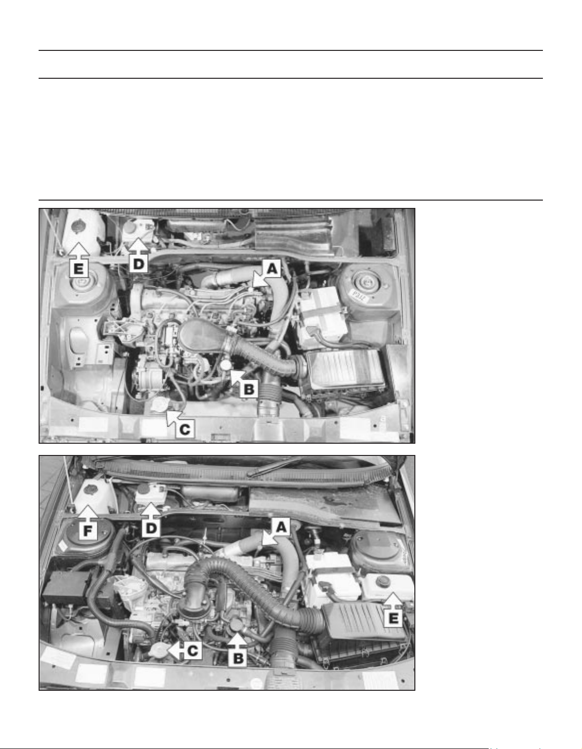
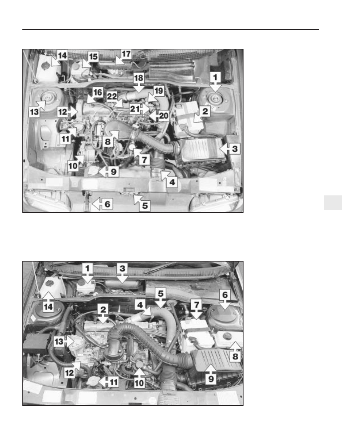
Underbonnet view of a 1580 cc carburettor engine
1 Left-hand suspension strut
top mounting
2 Battery
3 Air filter housing
4 Cold air inlet duct
5 Bonnet lock
6 Bonnet release latch
7 Engine oil filler cap/tube
8 Carburettor air inlet duct
(carburettor below)
9 Radiator (coolant filler) cap
10 Alternator
11 Right-hand engine mounting
12 Timing belt upper cover
13 Right-hand suspension strut
top mounting
14 Windscreen wash reservoir
15 Brake hydraulic fluid reservoir
16 Camshaft cover
17 Windscreen wiper motor
(beneath cover)
18 Hot air inlet duct
19 Engine oil level dipstick
20 Fuel pump
21 Distributor
22 Spark plug HT leads
Underbonnet view of a 1580 cc fuel injection engine
1 Brake hydraulic fluid reservoir
2 Valve cover
3 Windscreen wiper motor
(beneath cover)
4 Engine oil level dipstick
5 Hot air duct
6 Left-hand suspension strut
top mounting
7 Battery
8 Power steering fluid reservoir
9 Air cleaner
10 Engine oil filler cap/tube
11 Radiator (coolant filler) cap
12 Alternator
13 Right-hand engine mounting
14 Windscreen washer reservoir
Page 23
1•6 Maintenance & Servicing
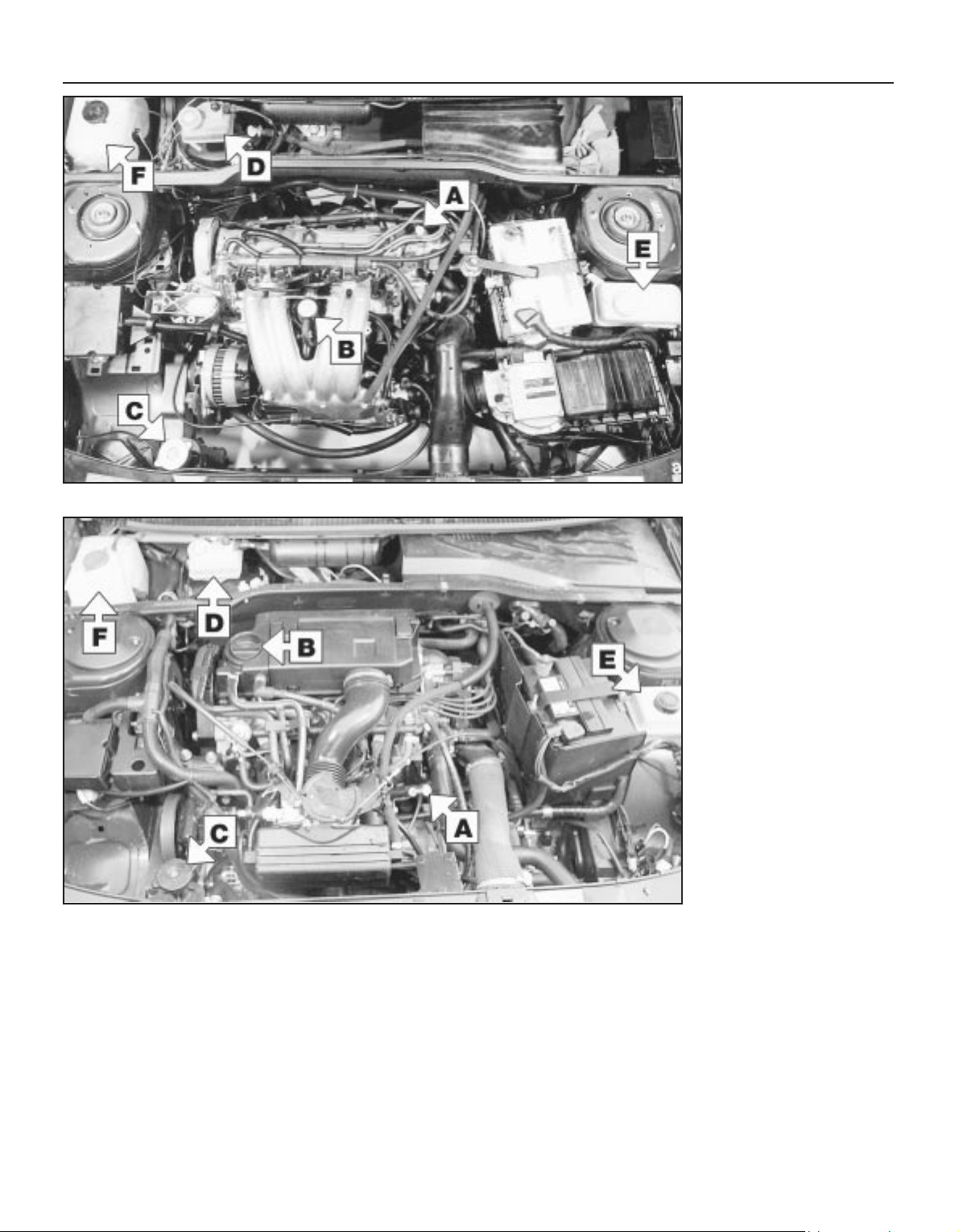
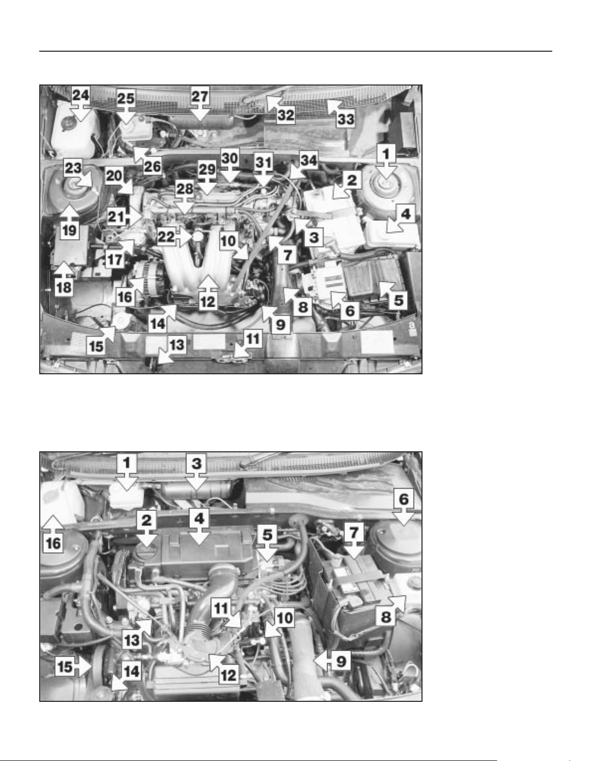
Underbonnet view of a 1998 cc engine
1 Brake system hydraulic fluid
reservoir
2 Engine oil filler cap
3 Windscreen wiper motor
(below cover)
4 Air cleaner cover
5 Ignition coil
6 Left-hand suspension strut
top mounting
7 Battery
8 Power steering fluid reservoir
9 Inlet air duct
10 Engine oil level dipstick
11 Automatic transmission
kickdown cable
12 Throttle housing
13 Accelerator cable
14 Radiator (coolant filler cap)
15 Auxiliary drivebelt
16 Windscreen washer fluid
reservoir
Underbonnet view of a 1905 cc engine
1 Left-hand strut top mounting
2 Battery
3 Fuel damper
4 Power steering fluid reservoir
5 Air filter cover
6 Fuel injection control unit
7 Thermostat housing
8 Cold air inlet
9 Throttle housing
10 Brake servo vacuum hose
11 Bonnet lock
12 Inlet manifold
13 Bonnet release latch
14 Accelerator cable
15 Radiator (coolant filler cap)
16 Alternator
17 Right-hand engine mounting
18 Fuel injection relay box
19 Right-hand strut top mounting
20 Camshaft drivebelt top cover
21 Fuel pressure regulator
22 Engine oil filler tube
23 Earth lead
24 Windscreen washer reservoir
25 Brake hydraulic fluid reservoir
26 Brake servo vacuum unit
27 Windscreen wiper motor
28 Fuel rail and injectors
29 Camshaft cover
30 Power steering hose
31 Engine oil level dipstick
32 Windscreen wiper arm
33 Air inlet grille (ventilation)
34 Distributor
Page 24
Maintenance & Servicing 1•7
1
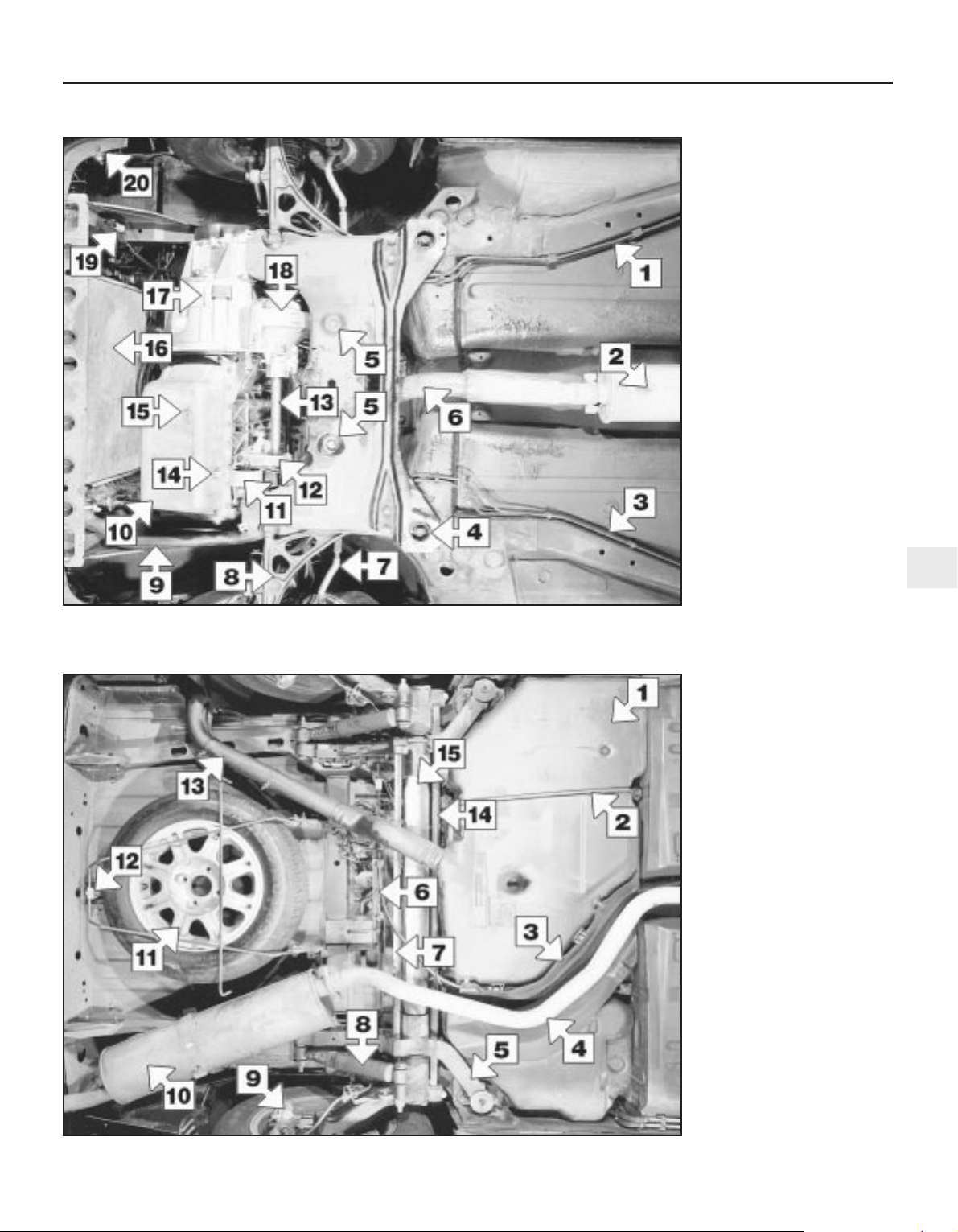
Rear underbody view of a 1905 cc engine model
1 Fuel tank
2 Fuel tank supporting strap
3 Heat shield
4 Exhaust pipe
5 Rear suspension side member
6 Handbrake cable equaliser
mechanism
7 Rear suspension torsion bar
8 Rear shock absorber
9 Rear disc brake caliper
10 Exhaust rear silencer
11 Spare wheel (cover removed)
12 Spare wheel cradle support
hook
13 Fuel filler hose
14 Rear anti-roll bar
15 Suspension cross-link
Front underbody view of a 1905 cc engine model
1 Fuel lines
2 Front exhaust silencer
3 Brake lines
4 Front subframe rear mounting
5 Steering rack mountings
6 Exhaust downpipe
7 Steering tack rod
8 Lower suspension arm
9 Radiator lower hose
10 Engine oil sump
11 Rear engine mounting
12 Driveshaft intermediate
bearing housing
13 Right-hand driveshaft
14 Oil temperature sensor
15 Engine oil drain plug
16 Radiator
17 Transmission housing
18 Differential housing
19 Cooling fan resistor
20 Horn
Page 25

Maintenance procedures
1•8 6000 Mile / 6 Month Service
1 Introduction
General information
1 This Chapter is designed to help the home
mechanic maintain his/her vehicle for safety,
economy, long life and peak performance.
2 The Chapter contains a master
maintenance schedule, followed by Sections
dealing specifically with each task in the
schedule. Visual checks, adjustments,
component renewal and other helpful items
are included. Refer to the accompanying
illustrations of the engine compartment and
the underside of the vehicle for the locations
of the various components.
3 Servicing your vehicle in accordance with
the mileage/time maintenance schedule and
the following Sections will provide a planned
maintenance programme, which should result
in a long and reliable service life. This is a
comprehensive plan, so maintaining some
items but not others at the specified service
intervals, will not produce the same results.
4 As you service your vehicle, you will
discover that many of the procedures can and should - be grouped together, because of
the particular procedure being performed, or
because of the close proximity of two
otherwise-unrelated components to one
another. For example, if the vehicle is raised
for any reason, the exhaust can be inspected
at the same time as the suspension and
steering components.
5 The first step in this maintenance
programme is to prepare yourself before the
actual work begins. Read through all the
Sections relevant to the work to be carried
out, then make a list and gather together all
the parts and tools required. If a problem is
encountered, seek advice from a parts
specialist, or a dealer service department.
2 Intensive maintenance
1 If, from the time the vehicle is new, the
routine maintenance schedule is followed
closely, and frequent checks are made of fluid
levels and high-wear items, as suggested
throughout this manual, the engine will be
kept in relatively good running condition, and
the need for additional work will be minimised.
2 It is possible that there will be times when
the engine is running poorly due to the lack of
regular maintenance. This is even more likely
if a used vehicle, which has not received
regular and frequent maintenance checks, is
purchased. In such cases, additional work
may need to be carried out, outside of the
regular maintenance intervals.
3 If engine wear is suspected, a compression
test will provide valuable information
regarding the overall performance of the main
internal components. Such a test can be used
as a basis to decide on the extent of the work
to be carried out. If, for example, a
compression test indicates serious internal
engine wear, conventional maintenance as
described in this Chapter will not greatly
improve the performance of the engine, and
may prove a waste of time and money, unless
extensive overhaul work is carried out first.
4 The following series of operations are those
most often required to improve the
performance of a generally poor-running
engine:
Primary operations
a) Clean, inspect and test the battery (see
“Weekly checks”).
b) Check all the engine-related fluids (see
“Weekly checks”).
c) Check the condition and tension of the
auxiliary drivebelt (Section 5).
d) Renew the spark plugs (Section 11).
e) Inspect the distributor cap and HT leads -
as applicable (Section 22).
f) Check the condition of the air cleaner
filter element, and renew if necessary
(Section 21).
g) Renew the fuel filter (Section 8).
h) Check the condition of all hoses, and
check for fluid leaks (Section 6).
i) Check the idle speed and mixture settings
- as applicable (Section 10).
5 If the above operations do not prove fully
effective, carry out the following secondary
operations:
Secondary operations
a) Check the charging system (Chapter 5A).
b) Check the ignition system (Chapter 5B).
c) Check the fuel system (Chapter 4).
d) Renew the distributor cap and rotor arm -
as applicable (Chapter 5B).
e) Renew the ignition HT leads - as
applicable (Section 22).
6000 Mile / 6 Month Service
3 Engine oil and filter renewal
1
Note: On models from 1994, the maker’s
specified interval for this procedure is
9000 miles (15 000 km) or 12 months.
Note: A suitable square-section wrench may
be required to undo the sump drain plug on
some models. These wrenches cab be
obtained from most motor factors or your
Peugeot dealer.
1 Frequent oil and filter changes are the most
important preventative maintenance
procedures which can be undertaken by the
DIY owner. As engine oil ages, it becomes
diluted and contaminated, which leads to
premature engine wear.
2 Before starting this procedure, gather
together all the necessary tools and materials.
Also make sure that you have plenty of clean
rags and newspapers handy, to mop up any
spills. Ideally, the engine oil should be warm,
as it will drain better, and more built-up
sludge will be removed with it. Take care,
however, not to touch the exhaust or any
other hot parts of the engine when working
under the vehicle. To avoid any possibility of
scalding, and to protect yourself from
possible skin irritants and other harmful
contaminants in used engine oils, it is
advisable to wear gloves when carrying out
this work. Access to the underside of the
vehicle will be greatly improved if it can be
raised on a lift, driven onto ramps, or jacked
up and supported on axle stands (see
“Jacking and Vehicle Support”). Whichever
method is chosen, make sure that the vehicle
remains level, or if it is at an angle, so that the
drain plug is at the lowest point. Where
necessary remove the splash guard from
under the engine.
3 Slacken the drain plug about half a turn; on
some models, a square-section wrench may
be needed to slacken the plug (see
illustration). Position the draining container
under the drain plug, then remove the plug
completely. If possible, try to keep the plug
3.3 Slackening the sump drain plug with a
square-section wrench
Page 26
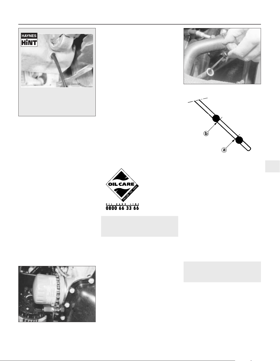
pressed into the sump while unscrewing it by
hand the last couple of turns (see Haynes
Hint) .
4 Recover the sealing ring from the drain
plug.
5 Allow some time for the old oil to drain,
noting that it may be necessary to reposition
the container as the oil flow slows to a trickle.
6 After all the oil has drained, wipe off the
drain plug with a clean rag. Check the sealing
washer for condition, and renew it if
necessary. Clean the area around the drain
plug opening, then refit and tighten the plug.
7 If the filter is also to be renewed, move the
container into position under the oil filter
which is located on the front side of the
cylinder block, below the inlet manifold.
8 Using an oil filter removal tool if necessary,
slacken the filter initially, then unscrew it by
hand the rest of the way (see illustration).
Empty the oil from the old filter into the
container, and discard the filter.
9 Use a clean rag to remove all oil, dirt and
sludge from the filter sealing area on the
engine. Check the old filter to make sure that
the rubber sealing ring hasn’t stuck to the
engine. If it has, carefully remove it.
10 Apply a light coating of clean engine oil to
the sealing ring on the new filter, then screw it
into position on the engine. Tighten the filter
firmly by hand only - do not use any tools.
Wipe clean the filter and sump drain plug.
11 Remove the old oil and all tools from
under the car, then lower the car to the
ground (if applicable).
12 Remove the dipstick then unscrew the oil
filler cap from the cylinder head cover. Fill the
engine, using the correct grade and type of oil
(see “Weekly checks”). An oil can spout or
funnel may help to reduce spillage. Pour in
half the specified quantity of oil first, then wait
a few minutes for the oil to fall to the sump.
Continue adding oil a small quantity at a time
until the level is up to the lower mark on the
dipstick. Finally, bring the level up to the
upper mark on the dipstick. Insert the
dipstick, and refit the filler cap.
13 Start the engine and run it for a few
minutes; check for leaks around the oil filter
seal and the sump drain plug. Note that there
may be a delay of a few seconds before the oil
pressure warning light goes out when the
engine is first started, as the oil circulates
through the engine oil galleries and the new oil
filter, before the pressure builds up.
14 Switch off the engine, and wait a few
minutes for the oil to settle in the sump once
more. With the new oil circulated and the filter
completely full, recheck the level on the
dipstick, and add more oil as necessary.
15 Dispose of the used engine oil safely, with
reference to “General Repair Procedures” in
the Reference section of this manual.
4 Automatic transmission fluid
level check
1
Note: On models from 1994, the maker’s
specified interval for this procedure is
9000 miles (15 000 km) or 12 months.
1 Take the vehicle on a short journey, to
warm the transmission up to normal operating
temperature, then park the vehicle on level
ground. The fluid level is checked using the
dipstick located at the front of the engine
compartment, directly in front of the
engine/transmission. The dipstick top is
brightly-coloured (usually orange) for easy
identification.
2 With the engine idling and the selector lever
in the “P” (Park) position, withdraw the
dipstick from the tube, and wipe all the fluid
from its end with a clean rag or paper towel.
Insert the clean dipstick back into the tube as
far as it will go, then withdraw it once more.
Note the fluid level on the end of the dipstick;
it should be between the upper and lower
marks (see illustrations).
3 If topping-up is necessary, add the required
quantity of the specified fluid to the
transmission via the dipstick tube. Use a
funnel with a fine mesh gauze, to avoid
spillage, and to ensure that no foreign matter
enters the transmission. Note: Never overfill
the transmission so that the fluid level is above
the upper mark.
4 After topping-up, take the vehicle on a
short run to distribute the fresh fluid, then
recheck the level again, topping-up if
necessary.
5 Always maintain the level between the two
dipstick marks. If the level is allowed to fall
below the lower mark, fluid starvation may
result, which could lead to severe
transmission damage.
6 Frequent need for topping-up indicates that
there is a leak, which should be found and
corrected before it becomes serious.
5 Auxiliary drivebelt check
and renewal
3
Note: On models from 1994, the maker’s
specified interval for this procedure is
18 000 miles (30 000 km).
Note: Peugeot specify the use of a special
electronic tool (SEEM C.TRONIC type 105 belt
tensioning measuring tool) to correctly set the
auxiliary drivebelt tension. If access to this
equipment cannot be obtained, an
approximate setting can be achieved using
the method described below. If the method
described is used, the tension should be
6000 Mile / 6 Month Service 1•9
4.2a Withdrawing the automatic
transmission dipstick
4.2b Automatic transmission fluid dipstick
lower (a) and upper (b) fluid level markings
3.8 Using an oil filter removal tool to
slacken the oil filter
1
As the engine oil drain plug releases
from the threads, move it away sharply
so the stream of oil issuing from the
sump runs into the container, not up
your sleeve!
Note: It is
antisocial and
illegal to dump oil
down the drain.
To find the
location of your
local oil recycling
bank, call this
number free.
Page 27
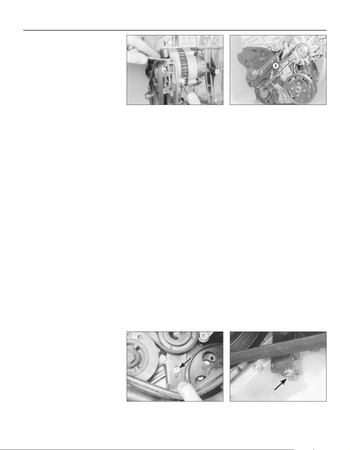
checked using the special electronic tool at
the earliest opportunity.
1 Except for XU9J4 16-valve engines, all
models are fitted with one auxiliary drivebelt
driven from the crankshaft pulley on the righthand side of the engine. On non-air
conditioning models the belt drives the
alternator and power steering pump and its
tension is adjusted manually. On models fitted
with air conditioning it drives the alternator,
power steering pump and the air conditioning
compressor. On XU9J4 models a separate
drivebelt drives the power steering pump from
a pulley on the end of the camshaft.
Checking the
auxiliary drivebelt condition
Except XU9J4 16-valve
power steering drivebelt
2 Apply the handbrake, then jack up the front
of the car and support it on axle stands (see
“Jacking and Vehicle Support”). Remove the
right-hand front roadwheel.
3 Remove the engine undercover and
wheelarch cover as applicable.
4 Using a suitable socket and extension bar
fitted to the crankshaft sprocket/pulley bolt,
rotate the crankshaft so that the entire length
of the drivebelt can be examined. Examine the
drivebelt for cracks, splitting, fraying or
damage. Check also for signs of glazing (shiny
patches) and for separation of the belt plies.
Renew the belt if worn or damaged.
5 If the condition of the belt is satisfactory, on
models where the belt is adjusted manually,
check the drivebelt tension as described
below. On models with an automatic springloaded tensioner, there is no need to check
the drivebelt tension.
XU9J4 16-valve
power steering drivebelt
6 The power steering drivebelt is positioned
on the left-hand end of the cylinder head.
Examine the full length of the drivebelt for
cracks, splitting, fraying or damage. If
necessary turn the engine with a spanner on
the crankshaft pulley or by engaging 4th gear
and pushing the car (for safety, the car must
be on level ground). Check also for signs of
glazing (shiny patches) and for separation of
the belt plies.
7 If the condition of the belt is satisfactory,
check the drivebelt tension as described later
in this Section.
Auxiliary drivebelt
(early models) - removal,
refitting and tensioning
Removal
8 Loosen the alternator pivot and link bolts,
then unscrew the adjuster bolt to release the
drivebelt tension (see illustration).
9 Remove the drivebelt from the alternator,
crankshaft and where necessary the power
steering pulleys.
Refitting and tensioning
10 Locate the drivebelt on the pulleys making
sure it is correctly engaged with the grooves.
11 The belt tension must be adjusted so that
with moderate thumb pressure applied midway along the belt’s longest run, it can be
deflected by approximately 6.0 mm. Turn the
adjuster bolt in or out to obtain the correct
tension, then tighten the pivot and link bolts
(see illustration).
Auxiliary drivebelt
(models with a manuallyadjusted tensioning pulley) removal, refitting and tensioning
Removal
12 If not already done, proceed as described
in paragraphs 2 and 3.
13 Disconnect the battery negative lead.
14 Slacken the tensioner pulley bracket
adjustment/mounting bolts (one located in the
middle of the pulley and the other located
below on the bracket (see illustration).
15 Fully tighten the adjustment bolt to its
stop, then slip the drivebelt from the pulleys
(see illustration).
Refitting
16 If the belt is being renewed, ensure that
the correct type is used. Fit the belt around
the pulleys, and take up the slack in the belt
by tightening the adjuster bolt. Ensure that the
ribs on the belt are correctly engaged with the
grooves in the pulleys.
17 Tension the drivebelt as described in the
following paragraphs.
Tensioning
18 If not already done, proceed as described
in paragraphs 2 and 3.
19 Correct tensioning of the drivebelt will
ensure that it has a long life. A belt which is
too slack will slip and perhaps squeal.
Beware, however, of overtightening, as this
can cause wear in the alternator bearings.
20 The belt should be tensioned so that,
under firm thumb pressure, there is approximately 5.0 mm of free movement at the midpoint between the pulleys on the longest belt
run (see the note at the start of this Section).
21 To adjust, unscrew the adjustment bolt
until the tension is correct, then rotate the
crankshaft a couple of times, and recheck the
tension. Securely tighten the tensioner pulley
bracket adjustment/mounting bolts.
22 Reconnect the battery negative lead.
23 Refit the engine undercover and
wheelarch cover. Refit the roadwheel, and
lower the vehicle to the ground.
Auxiliary drivebelt
(models with an automatic
spring-loaded tensioner pulley) removal, refitting and tensioning
Removal
24 If not already done, proceed as described
in paragraphs 2 and 3.
25 Disconnect the battery negative lead.
26 Using a square drive key in the square
hole in the bottom of the automatic adjuster
bracket, turn the bracket anticlockwise to
release the tension on the belt. Hold the
bracket in this position by inserting a 4.0 mm
1•10 6000 Mile / 6 Month Service
5.8 Loosening the alternator adjustment
bolts (early models)
5.14 Tensioner pulley bracket lower
mounting bolt (arrowed)
5.15 Auxiliary drivebelt tension adjustment
bolt (arrowed)
5.11 Alternator drivebelt deflection (A)
Page 28
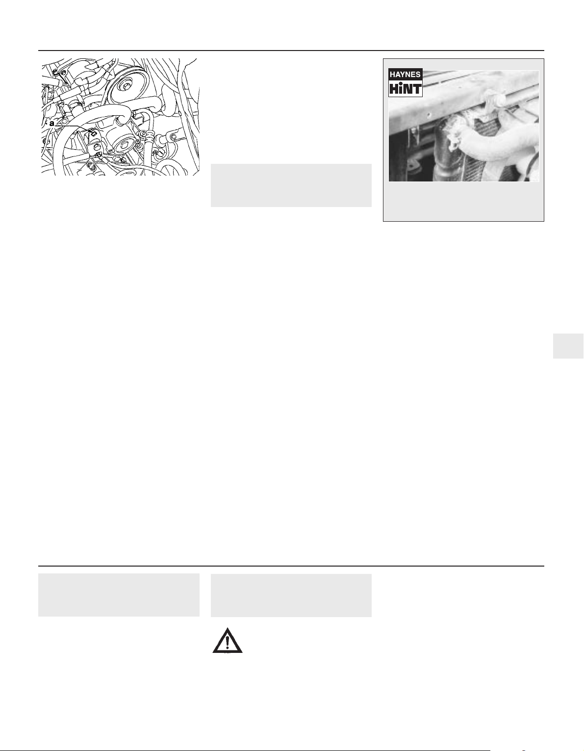
Allen key through the special hole and
tightening the peg.
27 Unscrew the mounting bolts and remove
the tensioner roller, then slip the auxiliary
drivebelt from the pulleys.
28 Check that the tensioner pulleys turn
freely without any sign of roughness.
Refitting and tensioning
29 If the belt is being renewed, ensure that
the correct type is used. Fit the belt around
the pulleys making sure that it is engaged with
the correct grooves in the pulleys.
30 Refit the tensioner roller and tighten the
mounting bolts.
31 Using the square drive key hold the
automatic adjuster, then release the peg and
slowly allow the tensioner to tighten the belt.
Check again that the belt is correctly located
in the pulley grooves.
32 Reconnect the battery negative lead.
33 Refit the engine undercover and
wheelarch cover. Refit the roadwheel, and
lower the vehicle to the ground.
Power steering pump drivebelt
(XU9J4 16-valve) models
Removal
34 Drain the hydraulic fluid from the system
as described in Chapter 10.
35 Loosen the pump mounting bolts and
remove the drivebelt.
36 Disconnect the high and low pressure
unions on the pump.
37 Remove the bolts and lift off the pump.
Refitting and tensioning
38 Refit in reverse order, then tension the
belt by applying a torque of 55 Nm for a new
belt and 30 Nm for a used belt by using the
square of a torque wrench in the square cutout in the pump bracket, tightening the
mounting bolts while the torque tension is
maintained (see illustration).
39 Fill and bleed the system (see Chapter 10).
6 Hose and fluid leak check
1
Note: On models from 1994, the maker’s
specified interval for this procedure is
9000 miles (15 000 km) or 12 months.
1 Visually inspect the engine joint faces,
gaskets and seals for any signs of water, oil or
fuel leaks. Pay particular attention to the areas
around the camshaft cover, cylinder head, oil
filter and sump joint faces. Bear in mind that,
over a period of time, some slight seepage
from these areas is to be expected. What you
are really looking for is any indication of a
serious leak. Should a leak be found, renew
the offending gasket or oil seal by referring to
the appropriate Chapters in this manual.
2 Also check the security and condition of all
the engine-related pipes and hoses. Ensure
that all cable-ties or securing clips are in place
and in good condition. Clips which are broken
or missing can lead to chafing of the hoses,
pipes, or wiring, which could cause more
serious problems in the future.
3 Carefully check the radiator hoses and
heater hoses along their entire length. Renew
any hose which is cracked, swollen, or
deteriorated. Cracks will show up better if the
hose is squeezed. Pay close attention to the
hose clips that secure the hoses to the
cooling system components. Hose clips can
pinch and puncture hoses, resulting in cooling
system leaks. If the original Peugeot crimpedtype hose clips are used, it may be a good
idea to replace them with standard wormdrive hose clips.
4 Inspect the cooling system (hoses, joint
faces, etc.) for leaks (see Haynes Hint).
5 Where any problems of this nature are
found on system components, renew the
component or gasket, referring to Chapter 3.
6 Where applicable, inspect the automatic
transmission fluid cooler hoses for leaks or
deterioration.
7 With the vehicle raised, inspect the petrol
tank and filler neck for punctures, cracks, and
other damage. The connection between the
filler neck and tank is especially critical.
Sometimes, a rubber filler neck or connecting
hose will leak due to loose retaining clamps or
deteriorated rubber.
8 Carefully check all rubber hoses and metal
fuel lines leading away from the petrol tank.
Check for loose connections, deteriorated
hoses, crimped lines, and other damage. Pay
particular attention to the vent pipes and
hoses, which often loop up around the filler
neck, and can become blocked or crimped.
Follow the lines to the front of the vehicle,
carefully inspecting them all the way. Renew
damaged sections as necessary.
9 From within the engine compartment,
check the security of all fuel hose attachments
and pipe unions, and inspect the fuel hoses
and vacuum hoses for kinks, chafing and
deterioration.
10 Where applicable, check the condition of
the power steering fluid hoses and pipes.
6000 Mile / 6 Month Service 1•11
1
5.38 Square cut-out in power steering
pump bracket (a) on XU9J4 16-valve models
A leak in the cooling system will usually
show up as white or rust coloured
deposits on the area adjoining the leak
12 000 Mile / 12 Month Service
7 Engine breather hose check
1
Check the condition and security of all
engine breather hoses.
Where the engine has covered a high
mileage, remove the hoses and clean any
sludge from them.
8 Fuel filter renewal
2
Note: On models from 1994, the maker’s
specified interval for this procedure is 18 000
miles (30 000 km) for carburettor models, and
36 000 miles (60 000 km) for fuel injection
models.
Carburettor models
1 The fuel filter is connected into the fuel
hose between the pump and the carburettor
in the engine compartment (see illustration).
2 To remove the filter, release the retaining
clips and disconnect the fuel hoses from the
filter. Where the original Peugeot crimped-
Warning: Before carrying out
the following operation, refer to
the precautions in “Safety first!”
and follow them implicitly.
Petrol is a highly-dangerous and volatile
liquid, and the precautions necessary
when handling it cannot be overstressed.
Page 29
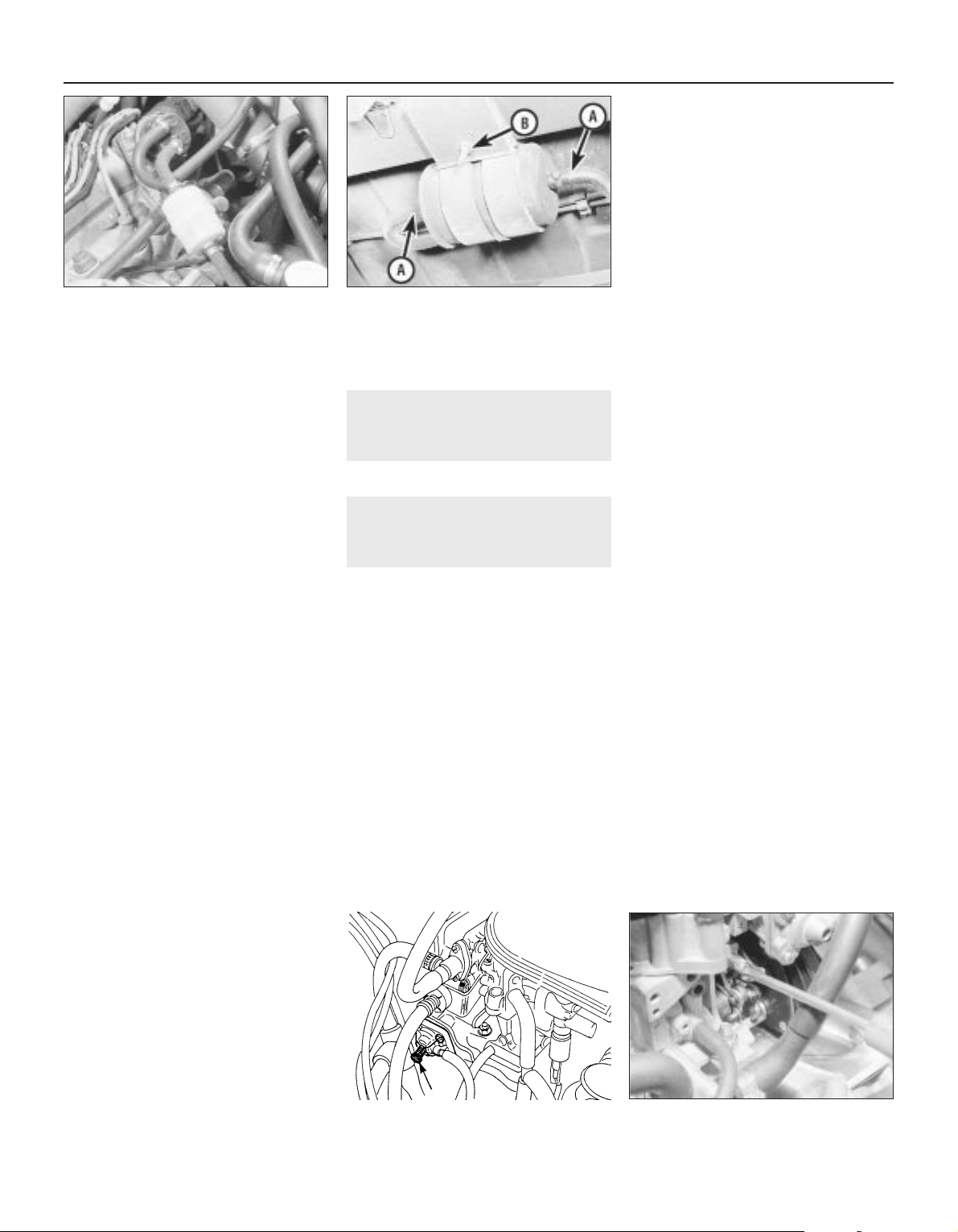
type hose clips are fitted, cut them off and
discard them; use standard worm-drive hose
clips on refitting.
3 Note the direction of the arrow marked on
the filter body. Unclip the filter from its
retaining bracket, and remove it from the
vehicle.
4 Connect the fuel hoses to the new filter.
Make sure that the arrow on the filter body is
pointing in the direction of the fuel flow, ie.
towards the fuel pump. Secure the hoses in
position by securely tightening the retaining
clips, then clip the filter back into position in
its retaining bracket.
5 At the same time, check the fuel reservoir
tank on the side of the carburettor for sediment.
Remove the reservoir as necessary for cleaning.
6 The fuel connections on the reservoir are as
follows.
a) Top hose - return to tank.
b) Middle hose - supply from pump via filter.
c) Lower hose - to carburettor inlet.
Fuel injection models
7 The fuel filter is situated underneath the rear
of the vehicle, mounted on the right-hand side
of the fuel tank. To gain access to the filter,
chock the front wheels, then jack up the rear
of the vehicle and support it on axle stands
(see “Jacking and Vehicle Support”).
8 Clamp the fuel hose on the tank side of the
filter. Bearing in mind the information given in
the relevant Part of Chapter 4 on depressurising the fuel system, release the clips and
disconnect the fuel hoses from the filter. Be
prepared for fuel spillage (see illustration).
9 Note the direction of the arrow marked on
the filter body. Slacken the retaining clamp
screw, then slide the filter out of the clamp,
and remove it from underneath the vehicle.
10 Dispose safely of the old filter; it will be
highly-inflammable, and may explode if
thrown on a fire.
11 Slide the new filter into position in the
clamp, ensuring that the arrow on the filter
body is pointing in the direction of the fuel
flow, ie. towards the throttle body/fuel rail.
This can be determined by tracing the fuel
hoses back along their length.
12 Connect the fuel hoses to the filter, and
secure them in position with their retaining
clips. Remove the hose clamp.
13 Start the engine, and check the filter hose
connections for leaks. Lower the vehicle to
the ground on completion.
9 Accelerator cable check
and adjustment
1
Refer to Chapter 4A or 4B.
10 Idle speed and mixture
check and adjustment
3
Note: On models from 1994, the maker’s
specified interval for this procedure is
18 000 miles (30 000 km).
1 Before checking the idle speed and mixture
setting, always check the following first:
a) Check that (where adjustable) the ignition
timing is accurate (Chapter 5B).
b) Check that the spark plugs are in good
condition and correctly gapped (Section 11).
c) Check that the accelerator cable (and on
carburettor models, the choke cable) is
correctly adjusted (refer to the relevant
Part of Chapter 4).
d) Check that the crankcase breather hoses
are secure, with no leaks or kinks
(Sections 7 and 29).
e) Check that the air cleaner filter element is
clean (Section 21).
f) Check that the exhaust system is in good
condition (refer to the relevant Part of
Chapter 4).
g) If the engine is running roughly, check the
compression pressures and valve
clearances as described in Chapter 2.
h) On fuel injection models, check that the
fuel injection/ignition system warning light
is not illuminated (refer to the relevant
Part of Chapter 4).
2 Take the car on a journey of sufficient
length to warm it up to normal operating
temperature. Note: Adjustment should ideally
be completed within two minutes of return,
without stopping the engine. If the radiator
electric cooling fan operates, wait for the
cooling fan to stop. If adjustment takes longer
than stated, regularly clear any excess fuel
from the inlet manifold by revving the engine
two or three times to about 2000 rpm, then
allow it to idle again.
Carburettor models
3 Ensure that all electrical loads are switched
off, and that the choke lever is pushed fully in.
If the car does not have a tachometer, connect
one following its manufacturer’s instructions.
Note the idle speed, and compare it with that
specified. Note: Models with air conditioning
have an idle compensation device, and the air
conditioning compressor must be running
while the idle speed is being checked and
adjusted.
4 Using a suitable flat-bladed screwdriver,
screw in the idle adjusting screw (to increase
the speed) or out as necessary to obtain the
specified speed. The screw is located on the
carburettor on non-air conditioning models,
and on the idle compensating device on air
conditioning models (see illustrations).
5 The idle mixture (exhaust gas CO level) is
set at the factory, and should require no
further adjustment. If, due to a change in
engine characteristics (carbon build-up, bore
wear etc) or after a major carburettor
overhaul, the mixture becomes incorrect, it
can be reset. Note, however, that an exhaust
gas analyser (CO meter) will be required to
check the mixture, and to set it with the
necessary standard of accuracy. If this is not
available, the car must be taken to a Peugeot
dealer for the work to be carried out.
6 Follow the exhaust gas analyser
manufacturer’s instructions to check the
exhaust gas CO level. If adjustment is
required, it is made via mixture adjustment
1•12 12 000 Mile / 12 Month Service
8.1 Fuel filter location on
carburettor models
10.4a Idle speed adjustment screw
(arrowed) on models with idle compensation
10.4b Idle speed adjustment screw
8.8 Fuel filter on fuel injection models
showing fuel hoses (A) and clamp bolt (B)
Page 30
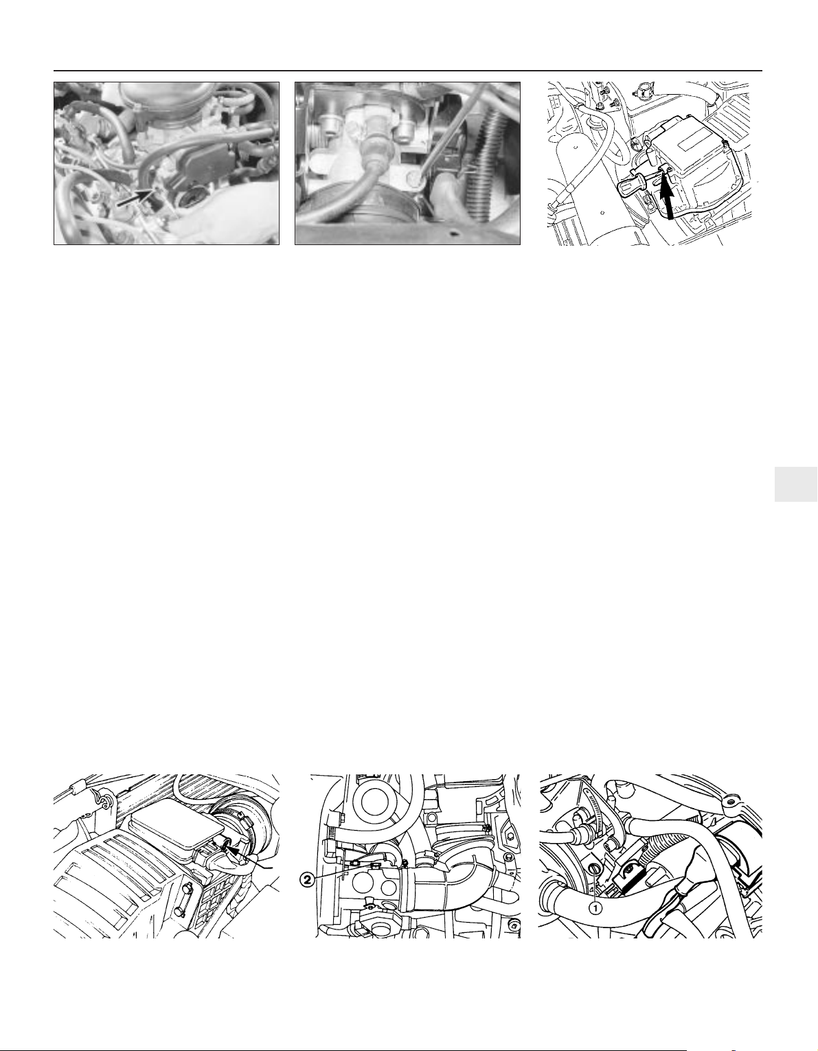
screw located on the carburettor. The screw
is covered with a tamperproof plug to prevent
unnecessary adjustment. To gain access to
the screw, use a sharp instrument to hook out
the plug.
7 Using a suitable flat-bladed screwdriver,
turn the mixture adjustment screw by very
small amounts until the level is correct (see
illustration). Screwing it in (clockwise)
weakens the idle mixture and reduces the CO
level; screwing it out will richen the mixture
and increase the CO level.
8 When adjustments are complete, disconnect
any test equipment, and fit a new tamperproof
plug to the mixture adjustment screw. Recheck
the idle speed and, if necessary, readjust.
Fuel injection models
Bosch L3.1-Jetronic system
9 Ensure that all electrical loads are switched
off. If the car does not have a tachometer,
connect one following its manufacturer’s
instructions. Note the idle speed, and
compare it with that specified.
10 The idle speed is adjusted using the idle
speed adjustment screw on the throttle
housing (see illustration). Turn the screw
clockwise to decrease the idle speed, or anticlockwise to increase the speed.
11 The idle mixture (exhaust gas CO level) is
set at the factory, and should require no
further adjustment. If, due to a change in
engine characteristics (carbon build-up, bore
wear etc) or after a major overhaul, the
mixture becomes incorrect, it can be reset.
Note, however, that an exhaust gas analyser
(CO meter) will be required to check the
mixture, and to set it with the necessary
standard of accuracy. If this is not available,
the car must be taken to a Peugeot dealer for
the work to be carried out.
12 Follow the exhaust gas analyser
manufacturer’s instructions to check the
exhaust gas CO level. If adjustment is
required, it is made via mixture adjustment
screw located on the airflow meter (see
Chapter 4C). The screw may be covered with
a tamperproof plug to prevent unnecessary
adjustment. To gain access to the screw, use
a sharp instrument to hook out the plug.
13 Using a flat-bladed screwdriver, turn the
mixture adjustment screw by small amounts
until the level is correct (see illustration).
14 When adjustments are complete, disconnect
any test equipment, and fit a new tamperproof
plug to the mixture adjustment screw. Recheck
the idle speed and, if necessary, readjust.
Bosch ML4.1 Motronic system
15 The idle speed is non-adjustable. It is
controlled by the idle speed regulator valve.
16 The idle mixture (exhaust gas CO level) is
set at the factory, and should require no
further adjustment. If, due to a change in
engine characteristics (carbon build-up, bore
wear etc) or after a major overhaul, the
mixture becomes incorrect, it can be reset.
Note, however, that an exhaust gas analyser
(CO meter) will be required to check the
mixture, and to set it with the necessary
standard of accuracy. If this is not available,
the car must be taken to a Peugeot dealer for
the work to be carried out.
17 Follow the exhaust gas analyser
manufacturer’s instructions to check the
exhaust gas CO level. If adjustment is
required, it is made via mixture adjustment
screw located on the airflow meter (see
illustration). The screw may be covered with
a tamperproof plug to prevent unnecessary
adjustment. To gain access to the screw, use
a sharp instrument to hook out the plug.
18 Turn the screw clockwise to increase and
anti-clockwise to decrease CO content until
the specified CO level is obtained.
19 When adjustments are complete,
disconnect any test equipment, and fit a new
tamperproof plug to the mixture adjustment
screw.
Bosch LU2-Jetronic system
20 The idle mixture is not adjustable and is
automatically regulated by the ECU.
21 To check the idle speed connect a
tachometer to the engine, then run the engine
at idle speed.
22 Turn the idle speed adjustment screw to
obtain the specified idle speed (see
illustration).
23 When adjustments are complete,
disconnect any test gear from the engine.
Bosch Motronic MP3.1 system
24 Ensure that all electrical loads are
switched off. If the car does not have a
tachometer, connect one following its
manufacturer’s instructions. Note the idle
speed, and compare it with that specified.
25 Turn the idle speed adjustment screw to
obtain the specified idle speed (see
illustration).
12 000 Mile / 12 Month Service 1•13
10.13 Mixture (CO) adjustment screw on
the Bosch L3.1 injection control unit
10.25 Idle speed adjustment screw (1) on
the Bosch Motronic MP3.1 system
10.22 Idle speed adjustment screw (2) on
the Bosch LU2-Jetronic injection system
10.17 Mixture (CO) adjustment screw
(arrowed) on Bosch ML4.1 Motronic system
10.10 Adjusting the idle speed screw on
the Bosch L3.1 injection system
1
10.7 Idle mixture adjustment screw
(arrowed)
Page 31

26 The idle mixture (exhaust gas CO level) is
set at the factory, and should require no
further adjustment. If, due to a change in
engine characteristics (carbon build-up, bore
wear etc) or after a major overhaul, the
mixture becomes incorrect, it can be reset.
Note, however, that an exhaust gas analyser
(CO meter) will be required to check the
mixture, and to set it with the necessary
standard of accuracy. If this is not available,
the car must be taken to a Peugeot dealer for
the work to be carried out.
27 Follow the exhaust gas analyser
manufacturer’s instructions to check the
exhaust gas CO level. If adjustment is
required, it is made via mixture adjustment
screw (see illustration). The screw may be
covered with a tamperproof plug to prevent
unnecessary adjustment. To gain access to
the screw, use a sharp instrument to hook out
the plug.
28 Turn the screw clockwise to increase and
anti-clockwise to decrease CO content until
the specified CO level is obtained.
29 When adjustments are complete,
disconnect any test equipment, and fit a new
tamperproof plug to the mixture adjustment
screw.
Bosch Motronic M1.3 fuel injection
system
30 The idle speed is only adjustable on the
XU9JA/Z engine - on other engines it is
controlled by the ECU and idle speed control
valve.
31 Ensure that all electrical loads are
switched off. If the car does not have a
tachometer, connect one following its
manufacturer’s instructions. Note the idle
speed, and compare it with that specified.
32 Turn the idle speed adjustment screw to
obtain the specified idle speed (see
illustration).
33 The idle mixture (CO) is only adjustable on
the XU9J4/K engine - on other engines it is
controlled by the ECU.
34 The idle mixture (exhaust gas CO level) is
set at the factory, and should require no
further adjustment. If, due to a change in
engine characteristics (carbon build-up, bore
wear etc) or after a major overhaul, the
mixture becomes incorrect, it can be reset.
Note, however, that an exhaust gas analyser
(CO meter) will be required to check the
mixture, and to set it with the necessary
standard of accuracy. If this is not available,
the car must be taken to a Peugeot dealer for
the work to be carried out.
35 Follow the exhaust gas analyser
manufacturer’s instructions to check the
exhaust gas CO level. If adjustment is
required, it is made via mixture adjustment
screw located on top of the airflow meter
assembly (see illustration). The screw may
be covered with a tamperproof plug to
prevent unnecessary adjustment. To gain
access to the screw, use a sharp instrument
to hook out the plug.
36 Turn the screw clockwise to increase and
anti-clockwise to decrease CO content until
the specified CO level is obtained.
All other fuel injection systems
37 Experienced home mechanics, with a
considerable amount of skill and equipment
(including a tachometer and an accurate
exhaust gas analyser) may be able to check
the exhaust CO level and the idle speed.
However, if these are found to be in need of
adjustment, the car must be taken to a
suitably-equipped Peugeot dealer.
38 On models with a Magneti Marelli engine
management (fuel injection/ignition) system,
adjustment of the mixture setting (exhaust gas
CO level) is possible, but adjustments can
only be made by reprogramming the engine
management ECU using special electronic
test equipment which is connected to the
diagnostic connector (see Chapter 4).
39 On all other vehicles, adjustments are not
possible. If the idle speed or the exhaust gas
CO level is incorrect, there must be a fault in
the engine management system, and the
vehicle should be taken to a Peugeot dealer
for testing (see Chapter 4).
11 Spark plug renewal
2
Note: On models from 1994, the maker’s
specified interval for this procedure is
18 000 miles (30 000 km).
1 The correct functioning of the spark plugs is
vital for the correct running and efficiency of
the engine. It is essential that the plugs fitted
are appropriate for the engine (the suitable
type is specified at the beginning of this
Chapter). If this type is used, and the engine is
in good condition, the spark plugs should not
need attention between scheduled
replacement intervals. Spark plug cleaning is
rarely necessary, and should not be
attempted unless specialised equipment is
available, as damage can easily be caused to
the firing ends.
2 On 16-valve models, to gain access to the
spark plugs, the access cover fitted over the
centre of the cylinder head must first be
removed. Undo the eight bolts, noting the
position of the wiring retaining clip, and
remove the cover (see illustration).
3 On other models, to improve access to
some of the plugs, it may be necessary to
remove the air inlet duct (refer to Chapter 4 for
further information).
4 On 1998 cc 16-valve models, pull the HT
coils off the spark plugs. If necessary, to
remove the possibility of the HT coils being
connected to the wrong spark plugs on
refitting, mark the coils 1 to 4 (No 1 cylinder is
at the transmission end of the engine).
5 On all other models, if the marks on the
original-equipment spark plug (HT) leads
cannot be seen, mark the leads 1 to 4,
corresponding to the cylinder the lead serves
(No 1 cylinder is at the transmission end of the
engine). Pull the leads from the plugs by
gripping the end fitting, not the lead,
otherwise the lead connection may be
fractured (see illustration).
1•14 12 000 Mile / 12 Month Service
10.27 Mixture (CO) adjustment screw (2)
on the Bosch MP3.1 fuel injection system
10.35 Mixture adjustment screw (5) on the
Bosch Motronic M1.3 fuel injection system
11.2 On 16-valve models undo the eight
bolts (arrowed) and remove the access
cover to reach the spark plugs
10.32 Idle speed adjustment screw (7) on
the Bosch Motronic M1.3 injection system
Page 32

6 It is advisable to remove the dirt from the
spark plug recesses, using a clean brush,
vacuum cleaner or compressed air before
removing the plugs, to prevent dirt dropping
into the cylinders.
7 Unscrew the plugs using a spark plug
spanner, suitable box spanner, or a deep
socket and extension bar (see illustration).
Keep the socket aligned with the spark plug if it is forcibly moved to one side, the ceramic
insulator may be broken off. As each plug is
removed, examine it as follows.
8 Examination of the spark plugs will give a
good indication of the condition of the engine.
If the insulator nose of the spark plug is clean
and white, with no deposits, this is indicative
of a weak mixture or too hot a plug (a hot plug
transfers heat away from the electrode slowly,
a cold plug transfers heat away quickly).
9 If the tip and insulator nose are covered
with hard black-looking deposits, then this is
indicative that the mixture is too rich. Should
the plug be black and oily, then it is likely that
the engine is fairly worn, as well as the mixture
being too rich.
10 If the insulator nose is covered with light
tan to greyish-brown deposits, then the
mixture is correct, and it is likely that the
engine is in good condition.
11 The spark plug electrode gap is of
considerable importance as, if it is too large or
too small, the size of the spark and its
efficiency will be seriously impaired. The gap
should be set to the value given in the Specifications at the beginning of this Chapter.
12 To set the gap, measure it with a feeler
blade, then bend the outer plug electrode until
the correct gap is achieved (see illustration).
The centre electrode should never be bent, as
this may crack the insulator and cause plug
failure, if nothing worse. If using feeler blades,
the gap is correct when the appropriate-size
blade is a firm, sliding fit.
13 Special spark plug electrode gap
adjusting tools are available from most motor
accessory shops, or from some spark plug
manufacturers.
14 Before fitting the spark plugs, check that
the threaded connector sleeves (on top of the
plug) are tight, and that the plug exterior
surfaces and threads are clean. It is very often
difficult to insert spark plugs into their holes
without cross-threading them. To avoid this
possibility, fit a short length of hose over the
end of the spark plug (see Haynes Hint).
15 Remove the rubber hose (if used), and
tighten the plug to the specified torque (see
“Specifications”) using the spark plug socket
and a torque wrench. Refit the remaining
plugs in the same way.
16 Connect the HT leads in the correct order,
and refit any components removed for
access. On 1998 cc 16-valve models, connect
the HT coils in their correct order.
12 Clutch adjustment check
and control mechanism
lubrication
2
Note: On models from 1994, the maker’s
specified interval for this procedure is
9000 miles (15 000 km) or 12 months for clutch
adjustment, and 18 000 miles (30 000 km) for
lubrication.
1 Check that the clutch pedal moves
smoothly and easily through its full travel.
2 The clutch itself should function correctly,
with no trace of slip or drag.
3 Where possible, adjust the clutch cable if
necessary, as described in Chapter 6.
4 If excessive effort is required to operate the
clutch, check first that the cable is correctly
routed and undamaged. Remove the pedal,
and make sure that its pivot is properly
greased. Refer to Chapter 6 for further
information.
13 Driveshaft gaiter check
1
Note: On models from 1994, the maker’s
specified interval for this procedure is
9000 miles (15 000 km) or 12 months.
With the vehicle raised and securely
supported on stands, turn the steering onto
full lock, then slowly rotate the roadwheel.
Inspect the condition of the outer constant
velocity (CV) joint rubber gaiters, while
squeezing the gaiters to open out the folds
(see illustration). Check for signs of cracking,
splits, or deterioration of the rubber, which
may allow the grease to escape, and lead to
water and grit entry into the joint. Also check
the security and condition of the retaining
clips. Repeat these checks on the inner CV
joints. If any damage or deterioration is found,
the gaiters should be renewed without delay
as described in Chapter 8.
At the same time, check the general
condition of the CV joints themselves, by first
holding the driveshaft and attempting to rotate
12 000 Mile / 12 Month Service 1•15
13.1 Check the condition of the driveshaft
gaiters (arrowed)
11.12 Measuring the spark plug gap with a
feeler blade
11.7 Tools required for spark plug
removal, gap adjustment and refitting
11.5 Pulling the HT leads
from the spark plugs
1
It is often difficult to insert spark plugs
into their holes without cross-threading
them. To avoid this possibility, fit a
short length of 5/16 inch internal
diameter rubber hose over the end of
the spark plug. The flexible hose acts as
a universal joint to help align the plug
with the plug hole. Should the plug
begin to cross-thread, the hose will slip
on the spark plug, preventing thread
damage to the cylinder head.
Page 33

the wheel. Repeat this check by holding the
inner joint and attempting to rotate the
driveshaft. Any obvious movement indicates
wear in the joints, wear in the driveshaft splines,
or a loose driveshaft retaining nut.
14 Front and rear
disc pad check
1
Note: On models from 1994, the maker’s
specified interval for this procedure is
18 000 miles (30 000 km) for the front brake
pads, and 36 000 miles (60 000 km) for the
rear brake pads or shoes.
1 Firmly apply the handbrake, then jack up
the front or rear of the car (as applicable) and
support it securely on axle stands (see
“Jacking and Vehicle Support”). Remove the
front or rear roadwheels.
2 If any pad’s friction material is worn to the
specified thickness or less, all four pads must
be renewed as a set.
3 For a comprehensive check, the brake pads
should be removed and cleaned. The
operation of the caliper can then also be
checked, and the condition of the brake disc
itself can be fully examined on both sides.
Refer to Chapter 9 for further information.
15 Handbrake check and
adjustment
3
Note: On models from 1994, the maker’s
specified interval for this procedure is
9000 miles (15 000 km) or 12 months.
Refer to Chapter 9.
16 Steering
and suspension check
2
Note: On models from 1994, the maker’s
specified interval for this procedure is
9000 miles (15 000 km) or 12 months.
Front suspension
and steering check
1 Raise the front of the car, and support on axle
stands (see “Jacking and Vehicle Support”).
2 Inspect the balljoint dust covers and the
steering rack-and-pinion gaiters for splits,
chafing or deterioration. Any wear of these
components will cause loss of lubricant, with
dirt and water entry, resulting in rapid
deterioration of the balljoints or steering gear.
3 On vehicles with power steering, check the
fluid hoses for chafing or deterioration, and
the pipe and hose unions for fluid leaks. Also
check for signs of fluid leakage under
pressure from the steering gear rubber
gaiters, which would indicate failed fluid seals
within the steering gear.
4 Grasp the roadwheel at the 12 o’clock
and 6 o’clock positions, and try to rock it (see
illustration). Very slight free play may be felt,
but if the movement is appreciable, further
investigation is necessary to determine the
source. Continue rocking the wheel while an
assistant depresses the footbrake. If the
movement is now eliminated or significantly
reduced, it is likely that the hub bearings are
at fault. If the free play is still evident with the
footbrake depressed, then there is wear in the
suspension joints or mountings.
5 Now grasp the wheel at the 9 o’clock
and 3 o’clock positions, and try to rock it as
before. Any movement felt now may again be
caused by wear in the hub bearings or the
steering track-rod balljoints. If the outer
balljoint is worn, the visual movement will be
obvious. If the inner joint is suspect, it can be
felt by placing a hand over the rack-and-pinion
rubber gaiter and gripping the track-rod. If the
wheel is now rocked, movement will be felt at
the inner joint if wear has taken place.
6 Using a large screwdriver or flat bar, check
for wear in the suspension mounting bushes
by levering between the relevant suspension
component and its attachment point. Some
movement is to be expected, as the
mountings are made of rubber, but excessive
wear should be obvious. Also check the
condition of any visible rubber bushes,
looking for splits, cracks or contamination of
the rubber.
7 With the car standing on its wheels, have an
assistant turn the steering wheel back and
forth, about an eighth of a turn each way.
There should be very little, if any, lost
movement between the steering wheel and
roadwheels. If this is not the case, closely
observe the joints and mountings previously
described. In addition, check the steering
column universal joints for wear, and also
check the rack-and-pinion steering gear itself.
Rear suspension check
8 Chock the front wheels, then jack up the
rear of the car and support on axle stands
(see “Jacking and Vehicle Support”).
9 Working as described previously for the
front suspension, check the rear hub
bearings, the suspension bushes and the
shock absorber mountings for wear.
Suspension strut/
shock absorber check
10 Check for any signs of fluid leakage
around the suspension strut/shock absorber
body, or from the rubber gaiter around the
piston rod. Should any fluid be noticed, the
suspension strut/shock absorber is defective
internally, and should be renewed. Note:
Suspension struts/shock absorbers should
always be renewed in pairs on the same axle.
11 The efficiency of the suspension
strut/shock absorber may be checked by
bouncing the vehicle at each corner.
Generally speaking, the body will return to its
normal position and stop after being
depressed. If it rises and returns on a
rebound, the suspension strut/shock
absorber is probably suspect. Examine also
the suspension strut/shock absorber upper
and lower mountings for any signs of wear.
17 Body drain channel check
1
Check and unblock all door and sill drain
channels. Also check the heater drain tube
located at the rear of the engine
compartment.
1•16 12 000 Mile / 12 Month Service
16.4 Check for wear in the hub bearings
by grasping the wheel and trying to rock it
For a quick check, the
thickness of friction material
remaining on each brake pad
can be measured through
the aperture in the caliper body.
Page 34

20 Coolant renewal
2
Note: On models from 1994, the maker’s
specified interval for this procedure is every
2 years, regardless of mileage.
Cooling system draining
1 With the engine completely cold, remove
the expansion tank filler cap. Turn the cap
anti-clockwise until it reaches the first stop.
Wait until any pressure remaining in the
system is released, then push the cap down,
turn it anti-clockwise to the second stop, and
lift it off.
2 Position a suitable container beneath the
coolant drain outlet at the lower left-hand side
of the radiator.
3 Loosen the drain plug (there is no need to
remove it completely) and allow the coolant to
drain into the container. If desired, a length of
tubing can be fitted to the drain outlet to
direct the flow of coolant during draining (see
illustration).
4 To assist draining, open the cooling system
bleed screws. On all except 1.4 litre engines,
the bleed screws are located in the thermostat
cover and thermostat housing. On 1.4 litre
engines, the bleed screws are located in the
thermostat housing, and in the cylinder head
coolant bypass hose. Additionally, on 2.0 litre
XU10J4 engines, there is a bleed screw
located in the coolant bypass hose behind the
cylinder head. All models also have a bleed
screw located at the top left-hand corner of
the radiator (see illustrations).
18 Hinge and lock lubrication
1
Note: On models from 1994, the maker’s
specified interval for this procedure is
36 000 miles (60 000 km).
1 Work around the vehicle, and lubricate the
hinges of the bonnet, doors and tailgate with a
light machine oil.
2 Lightly lubricate the bonnet release
mechanism and exposed section of inner
cable with a smear of grease.
3 Check carefully the security and operation
of all hinges, latches and locks, adjusting
them where required. Check the operation of
the central locking system (if fitted).
4 Check the condition and operation of the
tailgate struts, renewing them if either is
leaking or is no longer able to support the
tailgate securely when raised.
19 Air conditioning refrigerant
check
1
Note: On models from 1994, the maker’s
specified interval for this procedure is
18 000 miles (30 000 km).
1 In order to check the condition of the
refrigerant, a humidity indicator and a sight
glass are provided on top of the drier bottle,
located in the front, left-hand corner of the
engine compartment (see illustration).
Refrigerant humidity check
2 Check the colour of the humidity indicator.
Blue indicates that the condition of the
refrigerant is satisfactory. Pink indicates that
the refrigerant is saturated with humidity. If
the indicator shows red, the system should be
drained and recharged, and a new drier bottle
should be fitted. Note: The system should be
drained and recharged only by a Peugeot
dealer or air conditioning specialist. Do not
attempt to carry out the work yourself, as the
refrigerant is a highly-dangerous substance
(refer to Chapter 3).
Refrigerant flow check
3 Run the engine, and switch on the air
conditioning.
4 After a few minutes, inspect the sight glass,
and check the fluid flow. Clear fluid should be
visible - if not, the following will help to
diagnose the problem:
a) Clear fluid flow - the system is functioning
correctly.
b) No fluid flow - have the system checked
for leaks by a Peugeot dealer or air
conditioning specialist.
c) Continuous stream of clear air bubbles in
fluid - refrigerant level low - have the
system recharged by a Peugeot dealer or
air conditioning specialist.
d) Milky air bubbles visible - high humidity
(see paragraph 2).
18 000 Mile / 18 Month Service
18 000 Mile / 18 Month Service 1•17
20.4a Cooling system bleed screws on
thermostat housing and cover (arrowed) -
1.6 litre engine shown
19.1 Air conditioning system drier bottle
sight glass (1) and humidity indicator (2)
20.3 Radiator drain outlet (arrowed)
1
Warning: Do not attempt to
open the refrigerant circuit.
Refer to the precautions given
in Chapter 3.
24 000 Mile / 2 Year Service
Warning: Wait until the engine is
cold before starting this
procedure. Do not allow
antifreeze to come in contact
with your skin, or with the painted
surfaces of the vehicle. Rinse off spills
immediately with plenty of water. Never
leave antifreeze lying around in an open
container, or in a puddle in the driveway
or on the garage floor. Children and pets
are attracted by its sweet smell, but
antifreeze can be fatal if ingested.
Page 35

5 On 1.4 litre and 2.0 litre engines, when the
flow of coolant stops, reposition the container
below the cylinder block drain plug. On
1.4 litre engines, the drain plug is located at
the front left-hand end of the cylinder
block. On 2.0 litre engines, the drain plug is
located at the rear left-hand end of the
cylinder block, next to the rear engine
mounting (see illustrations). On 1.6, 1.8 and
1.9 litre engines, no cylinder block drain plug
is fitted.
6 Where applicable, remove the cylinder
block drain plug, and allow the coolant to
drain into the container.
7 If the coolant has been drained for a reason
other than renewal, then provided it is clean
and less than two years old, it can be re-used,
though this is not recommended.
8 Refit and tighten the radiator and cylinder
block drain plugs, as applicable, on
completion of draining.
Cooling system flushing
9 If coolant renewal has been neglected, or if
the antifreeze mixture has become diluted,
then in time, the cooling system may gradually
lose efficiency, as the coolant passages
become restricted due to rust, scale deposits,
and other sediment. The cooling system
efficiency can be restored by flushing the
system clean.
10 The radiator should be flushed
independently of the engine, to avoid
unnecessary contamination.
Radiator flushing
11 To flush the radiator, first tighten the
radiator drain plug, and the radiator bleed
screw, where applicable.
12 Disconnect the top and bottom hoses and
any other relevant hoses from the radiator,
with reference to Chapter 3.
13 Insert a garden hose into the radiator top
inlet. Direct a flow of clean water through the
radiator, and continue flushing until clean
water emerges from the radiator bottom
outlet.
14 If after a reasonable period, the water still
does not run clear, the radiator can be flushed
with a good proprietary cleaning agent. It is
important that the manufacturer’s instructions
are followed carefully. If the contamination is
particularly bad, insert the hose in the radiator
bottom outlet, and reverse-flush the radiator.
Engine flushing
15 To flush the engine, first refit and tighten
the cylinder block drain plug (where
applicable), and tighten the cooling system
bleed screws.
16 Remove the thermostat as described in
Chapter 3, then temporarily refit the
thermostat cover.
17 With the top and bottom hoses
disconnected from the radiator (see Chapter 3
- it may be preferable to disconnect the
bottom hose from the engine), insert a garden
hose into the radiator top hose. Direct a clean
flow of water through the engine, and
continue flushing until clean water emerges
from the radiator bottom hose.
18 On completion of flushing, refit the
thermostat and reconnect the hoses with
reference to Chapter 3.
Cooling system filling
19 Before attempting to fill the cooling
system, make sure that all hoses and clips are
in good condition, and that the clips are tight.
Note that an antifreeze mixture must be used
all year round, to prevent corrosion of the
engine components (see following subSection). Also check that the radiator and
cylinder block drain plugs, as applicable, are
in place and tight.
20 Remove the expansion tank cap.
21 Open all the cooling system bleed screws
(see paragraph 4).
22 Some of the cooling system hoses are
positioned at a higher level than the top of the
radiator expansion tank. It is therefore
necessary to use a “header tank” when
refilling the cooling system, to reduce the
possibility of air being trapped in the system.
Although Peugeot dealers use a special
header tank, the same effect can be achieved
by using a suitable bottle, with a seal between
the bottle and the expansion tank (see
illustration and Haynes Hint).
23 Fit the “header tank” to the expansion
tank and slowly fill the system. Coolant will
emerge from each of the bleed screws in turn,
starting with the lowest screw. As soon as
coolant free from air bubbles emerges from
the lowest screw, tighten that screw, and
watch the next bleed screw in the system.
Repeat the procedure until the coolant is
1•18 24 000 Mile / 2 Year Service
20.4b Coolant bypass hose bleed screw
(arrowed) - 1.4 litre engine
20.5a Cylinder block drain plug location
(arrowed) - 1.4 litre engine
20.22 Peugeot cooling system
“header tank” in position
20.5b Cylinder block drain plug location
(arrowed) - 2.0 litre engine
20.4c Radiator bleed screw (arrowed)
Cut the bottom off an old antifreeze
container to make a ‘header tank’ for
use when refilling the cooling system.
The seal at the point arrowed must be
as airtight as possible
Page 36

emerging from the highest bleed screw in the
cooling system and all bleed screws are
securely tightened. Keep the “header tank”
full during this procedure.
24 Once all the bleed screws are securely
tightened, remove the “header tank” and refit
the expansion tank cap.
25 Start the engine, and run it at 1500 rpm.
Maintain this engine speed until the radiator
cooling fan has cut in and out three times.
26 Allow the engine to run at idle speed for a
few minutes.
27 Stop the engine, and wait for at least ten
minutes.
28 Place a large wad of rag around the
expansion tank cap, and around your hand,
then carefully remove the expansion tank cap.
Turn the cap anti-clockwise until it reaches
the first stop. Wait until any pressure
remaining in the system is released, then push
the cap down, turn it anti-clockwise to the
second stop, and lift it off.
29 Check the coolant level, and if necessary
top-up the expansion tank to just above the
“MAXI” level mark (see “Weekly checks”).
30 Refit the expansion tank cap.
Antifreeze mixture
31 The antifreeze should always be renewed
at the specified intervals. This is necessary
not only to maintain the antifreeze properties,
but also to prevent corrosion which would
otherwise occur as the corrosion inhibitors
become progressively less effective.
32 Always use an ethylene-glycol based
antifreeze which is suitable for use in mixedmetal cooling systems. The quantity of
antifreeze and levels of protection are
indicated in the Specifications.
33 Before adding antifreeze, the cooling
system should be completely drained,
preferably flushed, and all hoses checked for
condition and security.
34 After filling with antifreeze, a label should
be attached to the expansion tank, stating the
type and concentration of antifreeze used,
and the date installed. Any subsequent
topping-up should be made with the same
type and concentration of antifreeze.
35 Do not use engine antifreeze in the
windscreen/tailgate washer system, as it will
cause damage to the vehicle paintwork. A
screenwash additive should be added to the
washer system in the quantities stated on the
bottle.
21 Air filter renewal
2
Note: On models from 1994, the maker’s
specified interval for this procedure is
36 000 miles (60 000 km).
TU models
1 Slacken the retaining clips (where fitted),
and disconnect the vacuum hose and
breather hose from the front of the air cleaner
housing-to-carburettor/throttle body duct
(see illustration). Where the crimped-type
Peugeot hose clips are fitted, cut the clips and
discard them; use standard worm-drive hose
clips on refitting.
2 Slacken the retaining clip securing the duct
to the carburettor/throttle body. Release the
retaining clips securing the lid to the top of the
air cleaner housing. Lift the duct and air
cleaner lid assembly away, and position it
clear of the air cleaner housing (see
illustrations).
3 Lift the air cleaner element out of the
housing (see illustration).
4 Fit the new element into the housing, and
secure it in position with the retaining clips.
5 Refit the sealing ring to the top of the filter
(where fitted), and refit the air cleaner-tocarburettor/throttle body duct. Ensure that the
duct and its sealing rings are correctly seated,
and securely tighten the retaining clips.
6 Reconnect the vacuum and breather hoses
to the duct, and secure them in position with
the retaining clips (where fitted).
XU models
(except XU10J4 16-valve)
with side-mounted air cleaner
7 Disconnect the air duct from the filter
housing cover to the carburettor/airflow meter
at the filter housing end (see illustration).
8 Release the clips and lift off the air cleaner
top cover (see illustration).
9 Withdraw the filter element from the air
cleaner body (see illustration).
10 Fit the new element in position in the air
cleaner body making sure that it is the right
way round.
24 000 Mile / 2 Year Service 1•19
21.2b . . . and remove the duct, positioning
it clear of the air cleaner housing
21.8 Lifting off the top cover21.7 Air filter housing cover located in the
left-hand front of the engine compartment
21.3 Removing the air cleaner element
on TU models
21.2a . . . then release the air cleaner lid
retaining clips, and the duct clip . . .
21.1 On TU models disconnect the hoses
from the front of the duct . . .
1
Warning: Take precautions
against scalding, as the cooling
system will be hot.
Page 37

11 Refit the top cover and attach the clips.
12 Reconnect the air duct.
XU models
(except XU10J4 16-valve)
with top-mounted air cleaner
13 Slacken the retaining clip, and disconnect
the inlet duct from the front of the cylinder
head cover (see illustration).
14 Slacken and remove the two retaining
screws situated at the front of the cylinder
head cover, then release the two air filter
cover retaining clips. Remove the filter cover
from the cylinder head cover, and withdraw
the filter element (see illustrations).
15 Fit the new element in position in the
cylinder head cover. Refit the filter cover, and
secure it with its retaining screws and clips.
16 Reconnect the inlet duct to the cylinder
head cover, and tighten its retaining clip.
XU10J4 16-valve models
17 Disconnect the air duct and remove the
cover from the end of the air cleaner body.
18 Withdraw the air filter element noting
which way round it is fitted.
19 Fit the new element in the body, ensuring
that it is fitted the correct way round.
20 Refit the cover and air duct.
22 Ignition system check
3
Note: On models from 1994, the maker’s
specified interval for this procedure is
18 000 miles (30 000 km).
1 The ignition system components should be
checked for damage or deterioration as
described under the relevant sub-heading.
Ignition systems
incorporating a distributor
General component check
2 The spark plug (HT) leads should be
checked whenever new spark plugs are
installed in the engine.
3 Ensure that the leads are numbered before
removing them, to avoid confusion when
refitting. Pull the leads from the plugs by
gripping the end fitting, not the lead,
otherwise the lead connection may be
fractured.
4 Check inside the end fitting for signs of
corrosion, which will look like a white crusty
powder. Push the end fitting back onto the
spark plug, ensuring that it is a tight fit on the
plug. If not, remove the lead again, and use
pliers to carefully crimp the metal connector
inside the end fitting until it fits securely on the
end of the spark plug.
5 Using a clean rag, wipe the entire length of
the lead to remove any built-up dirt and
grease. Once the lead is clean, check for
burns, cracks and other damage. Do not bend
the lead excessively, or pull the lead
lengthways - the conductor inside might
break.
6 Disconnect the other end of the lead from
the distributor cap. Again, pull only on the end
fitting. Check for corrosion and a tight fit in the
same manner as the spark plug end. If an
ohmmeter is available, check the resistance of
the lead by connecting the meter between the
spark plug end of the lead and the segment
inside the distributor cap. Refit the lead
securely on completion.
7 Check the remaining leads one at a time, in
the same way.
8 If new spark plug (HT) leads are required,
purchase a set for your specific car and
engine.
9 Remove the distributor cap by unscrewing
its retaining screws. Wipe it clean, and
carefully inspect it inside and out for signs of
cracks, carbon tracks (tracking) and worn,
burned or loose contacts; check that the
cap’s carbon brush is unworn, free to move
against spring pressure, and making good
contact with the rotor arm. Also inspect the
cap seal for signs of wear or damage, and
renew if necessary. Remove the rotor arm
from the distributor shaft and inspect it (see
illustration). It is common practice to renew
the cap and rotor arm whenever new spark
plug (HT) leads are fitted. When fitting a new
cap, remove the leads from the old cap one at
a time, and fit them to the new cap in the
exact same location - do not simultaneously
remove all the leads from the old cap, or firing
order confusion may occur. On refitting,
1•20 24 000 Mile / 2 Year Service
21.9 Removing the air filter element 21.14a . . . then slacken the retaining
screws (arrowed) . . .
21.14d . . . and withdraw the filter element21.14c Lift off the filter cover . . .21.14b . . . and release the retaining clips
21.13 Disconnect the intake duct from the
front of the cylinder head cover . . .
Warning: Voltages produced by
an electronic ignition system
are considerably higher than
those produced by conventional
ignition systems. Extreme care must be
taken if working on the system with the
ignition switched on. Persons with
surgically-implanted cardiac pacemaker
devices should keep well clear of the
ignition circuits, components and test
equipment.
Page 38

ensure that the arm is securely pressed onto
the shaft, and tighten the cap retaining screws
securely.
10 Even with the ignition system in first class
condition, some engines may still occasionally
experience poor starting, attributable to damp
ignition components. To disperse moisture, a
water-dispersant aerosol can be very
effective.
Ignition timing check and adjustment
11 Check the ignition timing as described in
Chapter 5B.
Static (distributorless)
ignition systems
General component check
12 On all except 1998 cc 16-valve models,
check the condition of the HT leads as
described above. On 1998 cc 16-valve
models, there are no HT leads, so the only
relevant check is that all the primary (LT)
circuit wiring connectors are clean and free of
corrosion.
Ignition timing check and adjustment
13 Refer to Chapter 5B.
23 Automatic transmission fluid
renewal
2
Note: On models from 1994, the maker’s
specified interval for this procedure is
18 000 miles (30 000 km).
1 Take the vehicle on a short run, to warm the
transmission up to normal operating
temperature.
2 Park the car on level ground, then switch off
the ignition and apply the handbrake firmly.
For improved access, jack up the front of the
car and support it securely on axle stands
(see “Jacking and Vehicle Support”). Note
that, when refilling and checking the fluid
level, the car must be lowered to the ground,
and level, to ensure accuracy.
3 Remove the dipstick, then position a
suitable container under the transmission. The
transmission has two drain plugs: one on the
sump, and another on the bottom of the
differential housing (see illustration).
4 Unscrew both drain plugs, and allow the
fluid to drain completely into the container.
5 When the fluid has finished draining, clean
the drain plug threads and those of the
transmission casing. Fit a new sealing washer
to each drain plug, and refit the plugs to the
transmission, tightening each securely. If the
car was raised for the draining operation, now
lower it to the ground. Make sure that the car
is level (front-to-rear and side-to-side).
6 Refilling the transmission is an awkward
operation, adding the specified type of fluid to
the transmission a little at a time via the
dipstick tube. Use a funnel with a fine mesh
gauze, to avoid spillage, and to ensure that no
foreign matter enters the transmission. Allow
plenty of time for the fluid level to settle
properly.
7 Once the level is up to the MAX mark on the
dipstick, refit the dipstick. Start the engine,
and allow it to idle for a few minutes. Switch
the engine off, then recheck the level,
topping-up if necessary. Take the car on a
short run to fully distribute the new fluid
around the transmission, then recheck the
fluid level as described in “Weekly checks”.
24 Brake fluid renewal
2
Note: On models from 1994, the maker’s
specified interval for this procedure is every
2 years, regardless of mileage.
1 The procedure is similar to that for the
bleeding of the hydraulic system as described
in Chapter 9, except that the brake fluid
reservoir should be emptied by siphoning,
using a clean poultry baster or similar before
starting, and allowance should be made for
the old fluid to be expelled when bleeding a
section of the circuit.
2 Working as described in Chapter 9, open
the first bleed screw in the sequence, and
pump the brake pedal gently until nearly all
the old fluid has been emptied from the
master cylinder reservoir. Top-up to the
“MAX” level with new fluid, and continue
pumping until only the new fluid remains in the
reservoir, and new fluid can be seen emerging
from the bleed screw. Tighten the screw, and
top the reservoir level up to the “MAX” level
line.
3 Work through all the remaining bleed
screws in the sequence until new fluid can be
seen at all of them. Be careful to keep the
master cylinder reservoir topped-up to above
the “MIN” level at all times, or air may enter
the system and greatly increase the length of
the task.
4 When the operation is complete, check that
all bleed screws are securely tightened, and
that their dust caps are refitted. Wash off all
traces of spilt fluid, and recheck the master
cylinder reservoir fluid level.
5 Check the operation of the brakes before
taking the car on the road.
24 000 Mile / 2 Year Service 1•21
23.3 Automatic transmission fluid drain
plugs (arrowed). Transmission is refilled
via the dipstick tube (1)
22.9 The rotor arm is a push fit on the
distributor shaft
1
Warning: If the fluid is hot, take
precautions against scalding.
Clean the drain plugs, being
especially careful to wipe any
metallic particles off the magnetic insert.
Discard the original sealing washers;
these should be renewed whenever they
are disturbed.
Warning: Brake hydraulic fluid
can harm your eyes and
damage painted surfaces, so
use extreme caution when
handling and pouring it. Do not use fluid
that has been standing open for some
time, as it absorbs moisture from the air.
Excess moisture content can cause a
dangerous loss of braking effectiveness.
Old hydraulic fluid is
invariably much darker in
colour than the new, making
it easy to distinguish the two.
Page 39

25 Timing belt renewal
4
Note: On models from 1994, the maker’s
specified interval for this procedure is
72 000 miles (120 000 km).
Refer to the relevant Part of Chapter 2.
26 Manual transmission
oil level check
2
Note: On models from 1994, the maker’s
specified interval for this procedure is
36 000 miles (60 000 km).
Note: A suitable square-section wrench may
be required to undo the transmission
filler/level plug on some models. These
wrenches can be obtained from most motor
factors or your Peugeot dealer.
Haynes Hint: It may be possible to use the
square end fitting on a ratchet handle (as
found in a typical socket set) to undo the
plug.
1 Park the car on a level surface. The oil level
must be checked before the car is driven, or
at least 5 minutes after the engine has been
switched off. If the oil level is checked
immediately after driving the car, some of the
oil will remain distributed around the
transmission components, resulting in an
inaccurate level reading.
2 Turn the steering wheel on full left-hand
lock, then where applicable remove the cover
for access to the left-hand side of the
transmission.
3 Wipe clean the area around the filler/level
plug, which is on the left-hand end of the
transmission. Unscrew the plug and clean it;
discard the sealing washer (see illustration).
4 The oil level should reach the lower edge of
the filler/level hole. A certain amount of oil will
have gathered behind the filler/level plug, and
will trickle out when it is removed; this does
not necessarily indicate that the level is
correct. To ensure that a true level is
established, wait until the initial trickle has
stopped, then add oil as necessary until a
trickle of new oil can be seen emerging (see
illustration). The level will be correct when
the flow ceases; use only good-quality oil of
the specified type.
5 Filling the transmission with oil is an
extremely awkward operation; above all, allow
plenty of time for the oil level to settle properly
before checking it. If a large amount had to be
added to the transmission, and a large
amount flows out on checking the level, refit
the filler/level plug and take the vehicle on a
short journey so that the new oil is distributed
fully around the transmission components,
then recheck the level when it has settled
again.
6 If the transmission has been overfilled so
that oil flows out as soon as the filler/level
plug is removed, first check that the car is
completely level (front-to-rear and side-toside), and allow any surplus oil to drain off into
a suitable container.
7 When the level is correct, fit a new sealing
washer to the filler/level plug. Refit the plug,
tightening it to the specified torque wrench
setting. Wash off any spilt oil then where
applicable refit the access cover.
27 Rear brake shoe check -
models with rear drum brakes
2
Note: On models from 1994, the maker’s
specified interval for this procedure is
36 000 miles (60 000 km).
Remove the rear brake drums, and check
the brake shoes for signs of wear or
contamination. At the same time, also inspect
the wheel cylinders for signs of leakage, and
the brake drum for signs of wear. Refer to the
relevant Sections of Chapter 9 for further
information.
28 Pollen filter renewal
1
Note: On models from 1994, the maker’s
specified interval for this procedure is
9000 miles (15 000 km) or 12 months.
1 On later models, a pollen filter is fitted.
2 Open the bonnet.
3 Release the securing clips, and withdraw
the plastic cover from the heater air inlet in the
passenger’s side of the scuttle at the rear of
the engine compartment.
4 Unclip the pollen filter from the heater air
inlet duct (see illustration).
5 Refitting is a reversal of removal.
29 Emissions control
systems check
2
Note: On models from 1994, the maker’s
specified interval for this procedure is
18 000 miles (30 000 km).
1 Details of the emission control system
components are given in Chapter 4D.
2 Checking consists simply of a visual check
for obvious signs of damaged or leaking
hoses and joints.
3 Detailed checking and testing of the
evaporative and/or exhaust emission systems
(as applicable) should be entrusted to a
Peugeot dealer.
30 Road test
1
Note: On models from 1994, the maker’s
specified interval for this procedure is
18 000 miles (30 000 km).
Instruments
and electrical equipment
1 Check the operation of all instruments and
electrical equipment.
36 000 Mile / 3 Year Service
1•22 36 000 Mile / 3 Year Service
28.4 Removing the pollen filter from the
heater air intake duct
26.4 Toping-up the transmission oil level
26.3 Using a square-section wrench to
unscrew the transmission filler/level plug
(MA transmission shown)
Page 40

2 Make sure that all instruments read correctly,
and switch on all electrical equipment in turn, to
check that it functions properly.
Steering and suspension
3 Check for any abnormalities in the steering,
suspension, handling or road “feel”.
4 Drive the vehicle, and check that there are
no unusual vibrations or noises.
5 Check that the steering feels positive, with
no excessive “sloppiness”, or roughness, and
check for any suspension noises when
cornering and driving over bumps.
Drivetrain
6 Check the performance of the engine, clutch
(where applicable), transmission and driveshafts.
7 Listen for any unusual noises from the
engine, clutch and transmission.
8 Make sure that the engine runs smoothly
when idling, and that there is no hesitation
when accelerating.
9 Check that, where applicable, the clutch
action is smooth and progressive, that the
drive is taken up smoothly, and that the pedal
travel is not excessive. Also listen for any
noises when the clutch pedal is depressed.
10 On manual transmission models, check
that all gears can be engaged smoothly
without noise, and that the gear lever action is
not abnormally vague or “notchy”.
11 On automatic transmission models, make
sure that all gearchanges occur smoothly,
without snatching, and without an increase in
engine speed between changes. Check that
all the gear positions can be selected with the
vehicle at rest. If any problems are found, they
should be referred to a Peugeot dealer.
12 Listen for a metallic clicking sound from
the front of the vehicle, as the vehicle is driven
slowly in a circle with the steering on full-lock.
Carry out this check in both directions. If a
clicking noise is heard, this indicates wear in a
driveshaft joint, in which case the complete
driveshaft must be renewed (see Chapter 8).
Braking system
13 Make sure that the vehicle does not pull to
one side when braking, and that the wheels
do not lock prematurely when braking hard.
14 Check that there is no vibration through
the steering when braking.
15 Check that the handbrake operates
correctly, without excessive movement of the
lever, and that it holds the vehicle stationary
on a slope.
16 Test the operation of the brake servo unit
as follows. Depress the footbrake four or five
times to exhaust the vacuum, then start the
engine. As the engine starts, there should be a
noticeable “give” in the brake pedal as
vacuum builds up. Allow the engine to run for
at least two minutes, and then switch it off. If
the brake pedal is now depressed again, it
should be possible to detect a hiss from the
servo as the pedal is depressed. After about
four or five applications, no further hissing
should be heard, and the pedal should feel
considerably harder.
36 000 Mile / 3 Year Service 1•23
1
Page 41

2A
Engine (general)
Designation . . . . . . . . . . . . . . . . . . . . . . . . . . . . . . . . . . . . . . . . . . . . . . . TU3
Engine code:
UK models (10/92 to 08/93) . . . . . . . . . . . . . . . . . . . . . . . . . . . . . . . . KDX (TU3MC/L/Z)
Non-UK models (07/87 to 06/88) . . . . . . . . . . . . . . . . . . . . . . . . . . . . K1A (TU3)
Non-UK models (07/88-on) . . . . . . . . . . . . . . . . . . . . . . . . . . . . . . . . . K1G (TU3A)
Non-UK models (11/87-on) . . . . . . . . . . . . . . . . . . . . . . . . . . . . . . . . . K3A (TU3TR)
Non-UK models (1993-on) . . . . . . . . . . . . . . . . . . . . . . . . . . . . . . . . . K2D (TU3F2/K)
Capacity . . . . . . . . . . . . . . . . . . . . . . . . . . . . . . . . . . . . . . . . . . . . . . . . . 1360 cc
Bore . . . . . . . . . . . . . . . . . . . . . . . . . . . . . . . . . . . . . . . . . . . . . . . . . 75.00 mm
Stroke . . . . . . . . . . . . . . . . . . . . . . . . . . . . . . . . . . . . . . . . . . . . . . . . . 77.00 mm
Direction of crankshaft rotation . . . . . . . . . . . . . . . . . . . . . . . . . . . . . . . Clockwise (viewed from right-hand side of vehicle)
No 1 cylinder location . . . . . . . . . . . . . . . . . . . . . . . . . . . . . . . . . . . . . . . At transmission end of block
Compression ratio:
Except K3A . . . . . . . . . . . . . . . . . . . . . . . . . . . . . . . . . . . . . . . . . . . . . 9.3 : 1
K3A . . . . . . . . . . . . . . . . . . . . . . . . . . . . . . . . . . . . . . . . . . . . . . . . . 8.3 : 1
*The engine code is situated on the front left-hand end of the cylinder block. It is either stamped on a plate which is riveted to the block
(aluminium block engines) or stamped directly on the cylinder block (cast-iron block engines). The code given in brackets is the factory identification number, and is not often referred to by this manual.
Camshaft
Drive . . . . . . . . . . . . . . . . . . . . . . . . . . . . . . . . . . . . . . . . . . . . . . . . . Toothed belt
Number of bearings . . . . . . . . . . . . . . . . . . . . . . . . . . . . . . . . . . . . . . . . 5
Camshaft bearing journal diameter (outside diameter):
No 1 . . . . . . . . . . . . . . . . . . . . . . . . . . . . . . . . . . . . . . . . . . . . . . . . . 36.950 to 36.925 mm
No 2 . . . . . . . . . . . . . . . . . . . . . . . . . . . . . . . . . . . . . . . . . . . . . . . . . 40.650 to 40.625 mm
No 3 . . . . . . . . . . . . . . . . . . . . . . . . . . . . . . . . . . . . . . . . . . . . . . . . . 41.250 to 41.225 mm
No 4 . . . . . . . . . . . . . . . . . . . . . . . . . . . . . . . . . . . . . . . . . . . . . . . . . 41.850 to 41.825 mm
No 5 . . . . . . . . . . . . . . . . . . . . . . . . . . . . . . . . . . . . . . . . . . . . . . . . . 42.450 to 42.425 mm
Cylinder head bearing journal diameter (inside diameter):
No 1 . . . . . . . . . . . . . . . . . . . . . . . . . . . . . . . . . . . . . . . . . . . . . . . . . 37.000 to 37.039 mm
No 2 . . . . . . . . . . . . . . . . . . . . . . . . . . . . . . . . . . . . . . . . . . . . . . . . . 40.700 to 47.739 mm
No 3 . . . . . . . . . . . . . . . . . . . . . . . . . . . . . . . . . . . . . . . . . . . . . . . . . 41.300 to 41.339 mm
No 4 . . . . . . . . . . . . . . . . . . . . . . . . . . . . . . . . . . . . . . . . . . . . . . . . . 41.900 to 41.939 mm
No 5 . . . . . . . . . . . . . . . . . . . . . . . . . . . . . . . . . . . . . . . . . . . . . . . . . 42.500 to 42.539 mm
Valve clearances (engine cold)
Inlet . . . . . . . . . . . . . . . . . . . . . . . . . . . . . . . . . . . . . . . . . . . . . . . . . 0.20 mm
Exhaust . . . . . . . . . . . . . . . . . . . . . . . . . . . . . . . . . . . . . . . . . . . . . . . . . 0.40 mm
Chapter 2 Part A:
TU petrol engine in-car repair procedures
Camshaft and rocker arms - removal, inspection and refitting . . . . .10
Camshaft oil seal - renewal . . . . . . . . . . . . . . . . . . . . . . . . . . . . . . . . .8
Compression test . . . . . . . . . . . . . . . . . . . . . . . . . . . . . . . . . . . . . . . . .2
Crankshaft oil seals - renewal . . . . . . . . . . . . . . . . . . . . . . . . . . . . . . .14
Cylinder head - removal and refitting . . . . . . . . . . . . . . . . . . . . . . . . .11
Cylinder head cover - removal and refitting . . . . . . . . . . . . . . . . . . . . .4
Engine assembly/valve timing holes -
general information and usage . . . . . . . . . . . . . . . . . . . . . . . . . . . . .3
Engine oil and filter renewal . . . . . . . . . . . . . . . . . . . . . . .See Chapter 1
Engine oil level check . . . . . . . . . . . . . . . . . . . . . .See “Weekly checks”
Engine/transmission mountings - inspection and renewal . . . . . . . . .16
Flywheel - removal, inspection and refitting . . . . . . . . . . . . . . . . . . . .15
General information . . . . . . . . . . . . . . . . . . . . . . . . . . . . . . . . . . . . . . .1
Oil pump - removal, inspection and refitting . . . . . . . . . . . . . . . . . . .13
Sump - removal and refitting . . . . . . . . . . . . . . . . . . . . . . . . . . . . . . .12
Timing belt - general information, removal and refitting . . . . . . . . . . . .6
Timing belt covers - removal and refitting . . . . . . . . . . . . . . . . . . . . . .5
Timing belt tensioner and sprockets -
removal, inspection and refitting . . . . . . . . . . . . . . . . . . . . . . . . . . .7
Valve clearances - checking and adjustment . . . . . . . . . . . . . . . . . . . .9
2A•1
Easy, suitable for
novice with little
experience
Fairly easy, suitable
for beginner with
some experience
Fairly difficult,
suitable for competent
DIY mechanic
Difficult, suitable for
experienced DIY
mechanic
Very difficult,
suitable for expert
DIY or professional
Degrees of difficulty
Specifications
Contents
Page 42

Lubrication system
Oil pump type . . . . . . . . . . . . . . . . . . . . . . . . . . . . . . . . . . . . . . . . . . . . . Gear-type, chain-driven off the crankshaft
Minimum oil pressure at 90°C:
Except K2D . . . . . . . . . . . . . . . . . . . . . . . . . . . . . . . . . . . . . . . . . . . . . 4 bars at 4000 rpm
K2D . . . . . . . . . . . . . . . . . . . . . . . . . . . . . . . . . . . . . . . . . . . . . . . . . 3 bars at 2000 rpm
Oil pressure warning switch operating pressure . . . . . . . . . . . . . . . . . . 0.8 bars
Torque wrench settings Nm lbf ft
Cylinder head cover nuts . . . . . . . . . . . . . . . . . . . . . . . . . . . . . . . . . . . . 16 12
Timing belt cover bolts . . . . . . . . . . . . . . . . . . . . . . . . . . . . . . . . . . . . . . 8 6
Crankshaft pulley retaining bolts . . . . . . . . . . . . . . . . . . . . . . . . . . . . . . 8 6
Timing belt tensioner pulley nut . . . . . . . . . . . . . . . . . . . . . . . . . . . . . . . 23 17
Camshaft sprocket retaining bolt . . . . . . . . . . . . . . . . . . . . . . . . . . . . . . 80 59
Crankshaft sprocket retaining bolt . . . . . . . . . . . . . . . . . . . . . . . . . . . . . 110 81
Camshaft thrust fork retaining bolt . . . . . . . . . . . . . . . . . . . . . . . . . . . . . 16 12
Cylinder head bolts (aluminium block engine):
Stage 1 . . . . . . . . . . . . . . . . . . . . . . . . . . . . . . . . . . . . . . . . . . . . . . . . 20 15
Stage 2 . . . . . . . . . . . . . . . . . . . . . . . . . . . . . . . . . . . . . . . . . . . . . . . . Angle-tighten a further 240°
Cylinder head bolts (cast-iron block engine):
Stage 1 . . . . . . . . . . . . . . . . . . . . . . . . . . . . . . . . . . . . . . . . . . . . . . . . 20 15
Stage 2 . . . . . . . . . . . . . . . . . . . . . . . . . . . . . . . . . . . . . . . . . . . . . . . . Angle-tighten a further 120°
Stage 3 . . . . . . . . . . . . . . . . . . . . . . . . . . . . . . . . . . . . . . . . . . . . . . . . Angle-tighten a further 120°
Sump drain plug . . . . . . . . . . . . . . . . . . . . . . . . . . . . . . . . . . . . . . . . . . . 30 22
Sump retaining nuts and bolts . . . . . . . . . . . . . . . . . . . . . . . . . . . . . . . . 8 6
Oil pump retaining bolts . . . . . . . . . . . . . . . . . . . . . . . . . . . . . . . . . . . . . 8 6
Flywheel retaining nuts and bolts . . . . . . . . . . . . . . . . . . . . . . . . . . . . . . 65 48
Piston oil jet spray tube bolts - 1587 cc models . . . . . . . . . . . . . . . . . . 10 7
Big-end bearing cap nuts . . . . . . . . . . . . . . . . . . . . . . . . . . . . . . . . . . . . 40 30
Main bearing ladder casting (aluminium block engine):
11 mm bolts:
Stage 1 . . . . . . . . . . . . . . . . . . . . . . . . . . . . . . . . . . . . . . . . . . . . . . 20 15
Stage 2 . . . . . . . . . . . . . . . . . . . . . . . . . . . . . . . . . . . . . . . . . . . . . . Angle-tighten a further 45°
6 mm bolts . . . . . . . . . . . . . . . . . . . . . . . . . . . . . . . . . . . . . . . . . . . . . 8 6
Main bearing cap bolts (cast-iron block engine):
Stage 1 . . . . . . . . . . . . . . . . . . . . . . . . . . . . . . . . . . . . . . . . . . . . . . . . 20 15
Stage 2 . . . . . . . . . . . . . . . . . . . . . . . . . . . . . . . . . . . . . . . . . . . . . . . . Angle-tighten a further 45°
2A•2 TU engine in-car repair procedures
1 General information
How to use this Chapter
1 This Part of Chapter 2 describes those
repair procedures that can reasonably be
carried out on the TU series engine while it
remains in the car. If the engine has been
removed from the car and is being dismantled
as described in Part C, any preliminary
dismantling procedures can be ignored. Refer
to Part B for the XU series petrol engine.
2 Note that, while it may be possible
physically to overhaul items such as the
piston/connecting rod assemblies while the
engine is in the car, such tasks are not
normally carried out as separate operations.
Usually, several additional procedures (not to
mention the cleaning of components and
oilways) have to be carried out. For this
reason, all such tasks are classed as major
overhaul procedures, and are described in
Part C of this Chapter.
3 Part C describes the removal of the
engine/transmission from the vehicle, and the
full overhaul procedures that can then be
carried out.
TU series engine description
4 The TU series engine is a well-proven
engine which has been fitted to many
previous Peugeot and Citroën vehicles. The
engine is of the in-line four-cylinder, overhead
camshaft (OHC) type, mounted transversely at
the front of the car. The clutch and
transmission are attached to its left-hand end.
The 405 range is fitted with the 1360 cc
version of the engine; carburettor and fuelinjected versions are available (carburettor
versions not available in the UK).
5 The crankshaft runs in five main bearings.
Thrustwashers are fitted to No 2 main bearing
(upper half) to control crankshaft endfloat.
6 The connecting rods rotate on horizontallysplit bearing shells at their big-ends. The
pistons are attached to the connecting rods
by gudgeon pins, which are an interference fit
in the connecting rod small-end eyes. The
aluminium-alloy pistons are fitted with three
piston rings - two compression rings and an
oil control ring.
7 Where the cylinder block is made of
aluminium, replaceable wet liners are fitted.
Sealing O-rings are fitted at the base of each
liner, to prevent the escape of coolant into the
sump.
8 Where the cylinder block is made from cast
iron, the cylinder bores are an integral part of
the cylinder block. On this type of engine the
cylinder bores are sometimes referred to as
having dry liners.
9 The inlet and exhaust valves are each
closed by coil springs, and operate in guides
pressed into the cylinder head; the valve seat
inserts are also pressed into the cylinder
head, and can be renewed separately if worn.
10 The camshaft is driven by a toothed
timing belt, and operates the eight valves via
rocker arms. Valve clearances are adjusted by
a screw-and-locknut arrangement. The
camshaft rotates directly in the cylinder head.
The timing belt also drives the coolant pump.
11 Lubrication is by means of an oil pump,
which is driven (via a chain and sprocket) off
the right-hand end of the crankshaft. It draws
oil through a strainer located in the sump, and
then forces it through an externally-mounted
filter into galleries in the cylinder
block/crankcase. From there, the oil is
distributed to the crankshaft (main bearings)
and camshaft. The big-end bearings are
supplied with oil via internal drillings in the
crankshaft, while the camshaft bearings also
receive a pressurised supply. The camshaft
lobes and valves are lubricated by splash, as
are all other engine components.
Page 43

12 Throughout this manual, it is often
necessary to identify the engines not only by
their capacity, but also by their engine code
which can be found on the left-hand end of
the front face of the cylinder block. On models
with an aluminium cylinder block the code is
stamped on a plate which is riveted to the
block, and on models with a cast iron cylinder
block the number is stamped on a machined
surface on the cylinder block, at the flywheel
end. The first part of the engine number gives
the engine code - eg “KDX” (see illustration).
Repair operations possible with
the engine in the car
13 The following work can be carried out with
the engine in the car:
a) Compression pressure - testing.
b) Cylinder head cover - removal and refitting.
c) Timing belt covers - removal and refitting.
d) Timing belt - removal, refitting and
adjustment.
e) Timing belt tensioner and sprockets -
removal and refitting.
f) Camshaft oil seal(s) - renewal.
g) Camshaft and rocker arms - removal,
inspection and refitting.*
h) Cylinder head - removal and refitting.
i) Cylinder head and pistons - decarbonising.
j) Sump - removal and refitting.
k) Oil pump - removal, overhaul and refitting.
l) Crankshaft oil seals - renewal.
m)Engine/transmission mountings -
inspection and renewal.
n) Flywheel - removal, inspection and refitting.
*The cylinder head must be removed for the
successful completion of this work. Refer to
Section 10 for details.
2 Compression test
1 When engine performance is down, or if
misfiring occurs which cannot be attributed to
the ignition or fuel systems, a compression
test can provide diagnostic clues as to the
engine’s condition. If the test is performed
regularly, it can give warning of trouble before
any other symptoms become apparent.
2 The engine must be fully warmed-up to
normal operating temperature, the battery
must be fully charged, and all the spark plugs
must be removed (Chapter 1). The aid of an
assistant will also be required.
3 On carburettor models, disable the ignition
system by disconnecting the ignition HT coil
lead from the distributor cap and earthing it
on the cylinder block. Use a jumper lead or
similar wire to make a good connection.
4 On fuel-injected models, disable the
ignition system by disconnecting the LT wiring
connector from the ignition HT coil(s),
referring to Chapter 5 for further information.
5 Fit a compression tester to the No 1
cylinder spark plug hole - the type of tester
which screws into the plug thread is to be
preferred.
6 Have the assistant hold the throttle wide
open, and crank the engine on the starter
motor. After one or two revolutions, the
compression pressure should build up to a
maximum figure, and then stabilise. Record
the highest reading obtained.
7 Repeat the test on the remaining cylinders,
recording the pressure in each.
8 All cylinders should produce very similar
pressures; a difference of more than 2 bars
between any two cylinders indicates a fault.
Note that the compression should build up
quickly in a healthy engine; low compression
on the first stroke, followed by graduallyincreasing pressure on successive strokes,
indicates worn piston rings. A low
compression reading on the first stroke, which
does not build up during successive strokes,
indicates leaking valves or a blown head
gasket (a cracked head could also be the
cause). Deposits on the undersides of the
valve heads can also cause low compression.
9 Although Peugeot do not specify exact
compression pressures, as a guide, any
cylinder pressure of below 10 bars can be
considered as less than healthy. Refer to a
Peugeot dealer or other specialist if in doubt
as to whether a particular pressure reading is
acceptable.
10 If the pressure in any cylinder is low, carry
out the following test to isolate the cause.
Introduce a teaspoonful of clean oil into that
cylinder through its spark plug hole, and
repeat the test.
11 If the addition of oil temporarily improves
the compression pressure, this indicates that
bore or piston wear is responsible for the
pressure loss. No improvement suggests that
leaking or burnt valves, or a blown head
gasket, may be to blame.
12 A low reading from two adjacent cylinders
is almost certainly due to the head gasket
having blown between them; the presence of
coolant in the engine oil will confirm this.
13 If one cylinder is about 20 percent lower
than the others and the engine has a slightly
rough idle, a worn camshaft lobe could be the
cause.
14 If the compression reading is unusually
high, the combustion chambers are probably
coated with carbon deposits. If this is the
case, the cylinder head should be removed
and decarbonised.
15 On completion of the test, refit the spark
plugs and reconnect the ignition system.
3 Engine assembly/valve
timing holes - general
information and usage
3
Note: Do not attempt to rotate the engine
whilst the crankshaft/camshaft are locked in
position. If the engine is to be left in this state
for a long period of time, it is a good idea to
place warning notices inside the vehicle, and
in the engine compartment. This will reduce
the possibility of the engine being accidentally
cranked on the starter motor, which is likely to
cause damage with the locking pins in place.
1 On all models, timing holes are drilled in the
camshaft sprocket and in the rear of the
flywheel. The holes are used to ensure that
the crankshaft and camshaft are correctly
positioned when assembling the engine (to
prevent the possibility of the valves contacting
the pistons when refitting the cylinder head),
or refitting the timing belt. When the timing
holes are aligned with the special holes in the
cylinder head and the front of the cylinder
block, suitable diameter pins can be inserted
to lock both the camshaft and crankshaft in
position, preventing them from rotating.
Proceed as follows.
2 Remove the timing belt upper cover as
described in Section 5.
3 The crankshaft must now be turned until
the timing hole in the camshaft sprocket is
aligned with the corresponding hole in the
cylinder head. The holes are aligned when the
camshaft sprocket hole is in the 2 o’clock
position, when viewed from the right-hand
end of the engine. The crankshaft can be
turned by using a spanner on the crankshaft
sprocket bolt, noting that it should always be
rotated in a clockwise direction (viewed from
the right-hand end of the engine).
4 With the camshaft sprocket hole correctly
positioned, insert a 6 mm diameter bolt or drill
through the hole in the front, left-hand flange
of the cylinder block, and locate it in the
timing hole in the rear of the flywheel (see
illustration). Note that it may be necessary to
TU engine in-car repair procedures 2A•3
3.4 Insert a 6 mm bolt (arrowed) through
hole in cylinder block flange and into
timing hole in the flywheel . . .
1.12 Engine code is stamped on a plate
(arrowed) attached to the front of the
cylinder block - viewed from above
2A
Page 44

rotate the crankshaft slightly, to get the holes
to align.
5 With the flywheel correctly positioned,
insert a 10 mm diameter bolt or a drill through
the timing hole in the camshaft sprocket, and
locate it in the hole in the cylinder head (see
illustration).
6 The crankshaft and camshaft are now
locked in position, preventing unnecessary
rotation.
4 Cylinder head cover -
removal and refitting
2
Removal
1 Disconnect the battery negative lead.
2 Where necessary, undo the bolts securing
the HT lead retaining clips to the rear of the
cylinder head cover, and position the clips
clear of the cover.
3 Slacken the retaining clip, and disconnect
the breather hose from the left-hand end of
the cylinder head cover (see illustration).
Where the original crimped-type Peugeot
hose clip is still fitted, cut it off and discard it.
Use a standard worm-drive clip on refitting.
4 Undo the two retaining nuts, and remove
the washer from each of the cylinder head
cover studs (see illustration).
5 Lift off the cylinder head cover, and remove
it along with its rubber seal (see illustration).
Examine the seal for signs of damage and
deterioration, and if necessary, renew it.
6 Lift off the spacer from each stud, and
remove the oil baffle plate (see illustrations).
Refitting
7 Carefully clean the cylinder head and cover
mating surfaces, and remove all traces of oil.
8 Fit the rubber seal over the edge of the
cylinder head cover, ensuring that it is
correctly located along its entire length (see
illustration).
9 Refit the oil baffle plate to the engine, and
locate the spacers in their recesses in the
baffle plate.
10 Carefully refit the cylinder head cover to
the engine, taking great care not to displace
the rubber seal.
11 Check that the seal is correctly located,
then refit the washers and cover retaining
nuts, and tighten them to the specified torque.
12 Where necessary, refit the HT lead clips to
the rear of the head cover, and securely
tighten their retaining bolts.
13 Reconnect the breather hose to the
cylinder head cover, securely tightening its
retaining clip, and reconnect the battery
negative lead.
5 Timing belt covers - removal
and refitting
2
Removal
Upper cover
1 Slacken and remove the two retaining bolts
(one at the front and one at the rear), and
remove the upper timing cover from the
cylinder head (see illustrations).
Centre cover
2 Remove the upper cover as described in
paragraph 1, then free the wiring from its clips
on the centre cover (see illustration).
3 Slacken and remove the three retaining
bolts (one at the rear of the cover, beneath the
engine mounting plate, and two directly above
the crankshaft pulley), and manoeuvre the
centre cover out from the engine
compartment (see illustration).
Lower cover
4 Remove the auxiliary drivebelt as described
in Chapter 1.
5 Remove the upper and centre covers as
described in paragraphs 1 to 3.
4.8 On refitting, ensure the rubber seal is
located on the cylinder head cover
2A•4 TU engine in-car repair procedures
3.5 . . . then insert a 10 mm bolt through
the cam sprocket timing hole, and locate it
in the cylinder head
4.4 . . . then slacken and remove the cover
retaining nuts and washers (arrowed) . . .
4.6b . . . and remove the oil baffle plate4.6a Lift off the spacers
(second one arrowed) . . .
4.5 . . . and lift off the cylinder head cover4.3 Disconnect the breather hose from the
cylinder head cover . . .
Page 45

6 Undo the three crankshaft pulley retaining
bolts and remove the pulley, noting which way
round it is fitted (see illustrations).
7 Slacken and remove the single retaining
bolt, and slide the lower cover off the end of
the crankshaft (see illustration).
Refitting
Upper cover
8 Refit the cover, ensuring it is correctly
located with the centre cover, and tighten its
retaining bolts.
Centre cover
9 Manoeuvre the centre cover back into
position, ensuring it is correctly located with
the lower cover, and tighten its retaining bolts.
10 Clip the wiring loom into its retaining clips
on the front of the centre cover, then refit the
upper cover as described in paragraph 8.
Lower cover
11 Locate the lower cover over the timing
belt sprocket, and tighten its retaining bolt.
12 Fit the pulley to the end of the crankshaft,
ensuring it is fitted the correct way round, and
tighten its retaining bolts to the specified
torque.
13 Refit the centre and upper covers as
described above, then refit and tension the
auxiliary drivebelt as described in Chapter 1.
6 Timing belt -
general information,
removal and refitting
4
Note: Peugeot specify the use of a special
electronic tool (SEEM C.TRONIC type 105 or
105.5 belt tensioning measuring tool) to
correctly set the timing belt tension. If access
to this equipment cannot be obtained, an
approximate setting can be achieved using
the method described below. If the method
described is used, the tension must be
checked using the special electronic tool at
the earliest possible opportunity. Do not drive
the vehicle over large distances, or use high
engine speeds, until the belt tension is known
to be correct. Refer to a Peugeot dealer for
advice.
General information
1 The timing belt drives the camshaft and
coolant pump from a toothed sprocket on the
front of the crankshaft. If the belt breaks or
slips in service, the pistons are likely to hit the
valve heads, resulting in extensive (and
expensive) damage.
2 The timing belt should be renewed at the
specified intervals (see Chapter 1), or earlier if
it is contaminated with oil, or if it is at all noisy
in operation (a “scraping” noise due to uneven
wear).
3 If the timing belt is being removed, it is a
wise precaution to check the condition of the
coolant pump at the same time (check for
signs of coolant leakage). This may avoid the
need to remove the timing belt again at a later
stage, should the coolant pump fail.
Removal
4 Disconnect the battery negative terminal.
5 Align the engine assembly/valve timing
holes as described in Section 3, and lock both
the camshaft sprocket and the flywheel in
position. Do not attempt to rotate the engine
whilst the locking tools are in position.
6 Remove the timing belt centre and lower
covers as described in Section 5.
7 Loosen the timing belt tensioner pulley
retaining nut. Pivot the pulley in a clockwise
direction, using a square-section key fitted to
the hole in the pulley hub, then retighten the
retaining nut.
8 If the timing belt is to be re-used, use white
paint or similar to mark the direction of
rotation on the belt (if markings do not already
exist) (see illustration). Slip the belt off the
sprockets.
9 Check the timing belt carefully for any signs
of uneven wear, splitting, or oil contamination.
Pay particular attention to the roots of the
teeth. Renew the belt if there is the slightest
TU engine in-car repair procedures 2A•5
5.2 Free the wiring loom from its
retaining clip . . .
5.6b . . . and remove the crankshaft pulley5.6a Undo the three retaining bolts
(arrowed) . . .
5.3 . . . then undo the three bolts (locations
arrowed) and remove the centre belt cover
5.1b . . . and remove the
upper timing belt cover
5.1a Undo the two retaining bolts
(arrowed) . . .
2A
5.7 Undo the retaining bolt and remove
the lower timing belt cover
Page 46

doubt about its condition. If the engine is
undergoing an overhaul, and has covered
more than 36 000 miles (60 000 km) with the
existing belt fitted, renew the belt as a matter
of course, regardless of its apparent
condition. The cost of a new belt is nothing
when compared to the cost of repairs, should
the belt break in service. If signs of oil
contamination are found, trace the source of
the oil leak, and rectify it. Wash down the
engine timing belt area and all related
components, to remove all traces of oil.
Refitting
10 Prior to refitting, thoroughly clean the
timing belt sprockets. Check that the
tensioner pulley rotates freely, without any
sign of roughness. If necessary, renew the
tensioner pulley as described in Section 7.
Make sure that the locking tools are still in
place, as described in Section 3.
11 Manoeuvre the timing belt into position,
ensuring the arrows on the belt are pointing in
the direction of rotation (clockwise, when
viewed from the right-hand end of the engine).
12 Do not twist the timing belt sharply while
refitting it. Fit the belt over the crankshaft and
camshaft sprockets. Make sure that the “front
run” of the belt is taut - ie, ensure that any
slack is on the tensioner pulley side of the
belt. Fit the belt over the coolant pump
sprocket and tensioner pulley. Ensure that the
belt teeth are seated centrally in the
sprockets.
13 Loosen the tensioner pulley retaining nut.
Pivot the pulley anti-clockwise to remove all
free play from the timing belt, then retighten
the nut. Tension the timing belt as described
under the relevant sub-heading.
Tensioning without the special
electronic measuring tool
Note: If this method is used, ensure that the
belt tension is checked by a Peugeot dealer at
the earliest possible opportunity.
14 Peugeot dealers use a special tool to
tension the timing belt. A similar tool may be
fabricated using a suitable square-section bar
attached to an arm made from a metal strip; a
hole should be drilled in the strip at a distance
of 80 mm from the centre of the squaresection bar. Fit the tool to the hole in the
tensioner pulley, keeping the tool arm as close
to the horizontal as possible, and hang a 1.5
kg (3.3 lb) weight (aluminium block engine) or
2.0 kg (4.4 lb) weight (cast-iron block engine)
from the hole in the tool (see illustration). In
the absence of an object of the specified
weight, a spring balance can be used to exert
the required force, ensuring that the spring
balance is held at 90° to the tool arm. Slacken
the pulley retaining nut, allowing the weight or
force exerted (as applicable) to push the
tensioner pulley against the belt, then
retighten the pulley nut.
15 If this special tool is not available, an
approximate setting may be achieved by
pivoting the tensioner pulley anti-clockwise
until it is just possible to twist the timing belt
through 90° by finger and thumb, midway
between the crankshaft and camshaft
sprockets. The deflection of the belt at the
mid-point between the sprockets should be
approximately 6.0 mm.
16 Remove the locking tools from the
camshaft sprocket and flywheel.
17 Using a suitable socket and extension bar
on the crankshaft sprocket bolt, rotate the
crankshaft through four complete rotations in
a clockwise direction (viewed from the righthand end of the engine). Do not at any time
rotate the crankshaft anti-clockwise.
18 Slacken the tensioner pulley nut, retension the belt as described in paragraph 14
or 15, then tighten the tensioner pulley nut to
the specified torque.
19 Rotate the crankshaft through a further
two turns clockwise, and check that both the
camshaft sprocket and flywheel timing holes
are still correctly aligned.
20 If all is well, refit the timing belt covers as
described in Section 5, and reconnect the
battery negative terminal.
Tensioning using the special
electronic measuring tool
21 Fit the special belt tensioning measuring
equipment to the “front run” of the timing belt,
approximately midway between the camshaft
and crankshaft sprockets. Position the
tensioner pulley so that the belt is tensioned
to a setting of 45 units, then retighten its
retaining nut.
22 Remove the locking tools from the
camshaft sprocket and flywheel, and remove
the measuring tool from the belt.
23 Using a suitable socket and extension bar
on the crankshaft sprocket bolt, rotate the
crankshaft through four complete rotations in
a clockwise direction (viewed from the righthand end of the engine). Do not at any time
rotate the crankshaft anti-clockwise.
24 Slacken the tensioner pulley retaining nut,
and refit the measuring tool to the belt. If a
“new” belt is being fitted, tension it to a
setting of 40 units. If an “old” belt is being reused, tighten it to a setting of 36 units. Note:
Peugeot state that a belt becomes “old” after
1 hour’s use. With the belt correctly
tensioned, tighten the pulley retaining nut to
the specified torque.
25 Remove the measuring tool from the belt,
then rotate the crankshaft through another
two complete rotations in a clockwise
direction, so that both the camshaft sprocket
and flywheel timing holes are realigned. Do
not at any time rotate the crankshaft anticlockwise. Fit the measuring tool to the belt,
and check the belt tension. A “new” belt
should give a reading of 51 ± 3 units; an “old”
belt should be 45 ± 3 units.
26 If the belt tension is incorrect, repeat the
procedures in paragraphs 24 and 25.
27 With the belt tension correctly set, refit the
timing belt covers as described in Section 5,
and reconnect the battery negative terminal.
7 Timing belt tensioner and
sprockets - removal,
inspection and refitting
4
Note: This Section describes the removal and
refitting of the components concerned as
individual operations. If more than one of them
is to be removed at the same time, start by
removing the timing belt as described in
Section 6; remove the actual component as
described below, ignoring the preliminary
dismantling steps.
Removal
1 Disconnect the battery negative terminal.
2 Position the engine assembly/valve timing
holes as described in Section 3, and lock both
the camshaft sprocket and flywheel in
position. Do not attempt to rotate the engine
whilst the pins are in position.
Camshaft sprocket
3 Remove the centre timing belt cover as
described in Section 5.
2A•6 TU engine in-car repair procedures
6.8 Mark the direction of rotation on the
belt, if it is to be re-used
6.14 Using the Peugeot special tool to
tension the timing belt
Page 47

4 Loosen the timing belt tensioner pulley
retaining nut. Rotate the pulley in a clockwise
direction, using a suitable square-section key
fitted to the hole in the pulley hub, then
retighten the retaining nut.
5 Disengage the timing belt from the
sprocket, and move the belt clear, taking care
not to bend or twist it sharply. Remove the
locking pin from the camshaft sprocket.
6 Slacken the camshaft sprocket retaining
bolt and remove it, along with its washer. To
prevent the camshaft rotating as the bolt is
slackened, a sprocket-holding tool will be
required. In the absence of the special
Peugeot tool, an acceptable substitute can be
fabricated as follows. Use two lengths of steel
strip (one long, the other short), and three nuts
and bolts; one nut and bolt forms the pivot of
a forked tool, with the remaining two nuts and
bolts at the tips of the “forks” to engage with
the sprocket spokes as shown in the
accompanying “Tool Tip”. Do not attempt to
use the sprocket locking pin to prevent the
sprocket from rotating whilst the bolt is
slackened.
7 With the retaining bolt removed, slide the
sprocket off the end of the camshaft. If the
locating peg is a loose fit in the rear of the
sprocket, remove it for safe-keeping. Examine
the camshaft oil seal for signs of oil leakage
and, if necessary, renew it as described in
Section 8.
Crankshaft sprocket
8 Remove the centre and lower timing belt
covers as described in Section 5.
9 Remove the timing belt from the sprockets
as described in Section 6.
10 To prevent crankshaft rotation whilst the
sprocket retaining bolt is slackened, select
4th gear, and have an assistant apply the
brakes firmly. If the engine has been removed
from the vehicle, lock the flywheel ring gear,
using an arrangement similar to that shown
(see illustration). Do not be tempted to use
the flywheel locking pin to prevent the
crankshaft from rotating; temporarily remove
the locking pin from the rear of the flywheel
prior to slackening the pulley bolt, then refit it
once the bolt has been slackened. Do not
allow the crankshaft to turn more than a few
degrees while loosening the bolt otherwise
the pistons may touch the valves.
11 Unscrew the retaining bolt and washer,
then slide the sprocket off the end of the
crankshaft (see illustrations). Refit the
locating pin to the rear of the timing hole in the
rear of the flywheel.
12 If the Woodruff key is a loose fit in the
crankshaft, remove it and store it with the
sprocket for safe-keeping. If necessary, also
slide the flanged spacer off the end of the
crankshaft (see illustration). Examine the
crankshaft oil seal for signs of oil leakage and,
if necessary, renew it (refer to Section 14).
Tensioner pulley
13 Remove the centre timing belt cover as
described in Section 5.
14 Slacken and remove the timing belt
tensioner pulley retaining nut, and slide the
pulley off its mounting stud. Examine the
mounting stud for signs of damage and, if
necessary, renew it.
Inspection
15 Clean the sprockets thoroughly, and
renew any that show signs of wear, damage
or cracks.
16 Clean the tensioner assembly, but do not
use any strong solvent which may enter the
pulley bearing. Check that the pulley rotates
freely about its hub, with no sign of stiffness
or free play. Renew the tensioner pulley if
there is any doubt about its condition, or if
there are any obvious signs of wear or
damage.
Refitting
Camshaft sprocket
17 Refit the locating peg (where removed) to
the rear of the sprocket, then locate the
sprocket on the end of the camshaft. Ensure
that the locating peg is correctly engaged with
the cutout in the camshaft end.
18 Refit the sprocket retaining bolt and
washer. Tighten the bolt to the specified
torque, whilst retaining the sprocket with the
tool used on removal (see Tool Tip).
19 Realign the timing hole in the camshaft
sprocket (see Section 3) with the
corresponding hole in the cylinder head, and
refit the locking pin.
20 Refit the timing belt to the camshaft
sprocket. Ensure that the “front run” of the
belt is taut - ie, ensure that any slack is on the
tensioner pulley side of the belt. Do not twist
the belt sharply while refitting it, and ensure
that the belt teeth are seated centrally in the
sprockets.
21 Loosen the tensioner pulley retaining nut.
Rotate the pulley anti-clockwise to remove all
free play from the timing belt, then retighten
the nut.
22 Tension the belt as described in
paragraphs 14 to 19 of Section 6.
23 Refit the timing belt covers as described
in Section 5.
Crankshaft sprocket
24 Where removed, locate the Woodruff key
in the crankshaft end, then slide on the
TU engine in-car repair procedures 2A•7
7.11b . . . then slide off the sprocket 7.12 Remove the flanged spacer if
necessary
7.11a Remove the crankshaft sprocket
retaining bolt . . .
7.10 Use the fabricated tool shown to lock
flywheel ring gear and prevent the
crankshaft rotating
2A
Using a home-made tool to hold the
camshaft sprocket stationary whilst the
retaining bolt is tightened (shown with
cylinder head removed)
Page 48

flanged spacer, aligning its slot with the
Woodruff key.
25 Align the crankshaft sprocket slot with the
Woodruff key, and slide it onto the end of the
crankshaft.
26 Temporarily remove the locking pin from
the rear of the flywheel, then refit the
crankshaft sprocket retaining bolt and
washer. Tighten the bolt to the specified
torque, whilst preventing crankshaft rotation
using the method employed on removal. Refit
the locking pin to the rear of the flywheel.
27 Relocate the timing belt on the sprockets.
Ensure that the “front run” of the belt is taut ie, ensure that any slack is on the tensioner
pulley side of the belt. Do not twist the belt
sharply while refitting it, and ensure that the
belt teeth are seated centrally in the
sprockets.
28 Loosen the tensioner pulley retaining nut.
Rotate the pulley anti-clockwise to remove all
free play from the timing belt, then retighten
the nut.
29 Tension the belt as described in
paragraphs 14 to 19 of Section 6.
30 Refit the timing belt covers as described
in Section 5.
Tensioner pulley
31 Refit the tensioner pulley to its mounting
stud, and fit the retaining nut.
32 Ensure that the “front run” of the belt is
taut - ie, ensure that any slack is on the pulley
side of the belt. Check that the belt is centrally
located on all its sprockets. Rotate the pulley
anti-clockwise to remove all free play from the
timing belt, then tighten the pulley retaining
nut securely.
33 Tension the belt as described in
paragraphs 14 to 19 of Section 6.
34 Refit the timing belt covers as described
in Section 5.
8 Camshaft oil seal - renewal
4
Note: If the camshaft oil seal is to be renewed
with the timing belt still in place, check first
that the belt is free from oil contamination.
(Renew the belt as a matter of course if signs
of oil contamination are found; see Section 6.)
Cover the belt to protect it from oil
contamination while work is in progress.
Ensure that all traces of oil are removed from
the area before the belt is refitted.
1 Remove the camshaft sprocket as
described in Section 7.
2 Punch or drill two small holes opposite
each other in the oil seal. Screw a self-tapping
screw into each, and pull on the screws with
pliers to extract the seal.
3 Clean the seal housing, and polish off any
burrs or raised edges, which may have
caused the seal to fail in the first place.
4 Lubricate the lips of the new seal with clean
engine oil, and drive it into position until it
seats on its locating shoulder. Use a suitable
tubular drift, such as a socket, which bears
only on the hard outer edge of the seal. Take
care not to damage the seal lips during fitting.
Note that the seal lips should face inwards.
5 Refit the camshaft sprocket as described in
Section 7.
9 Valve clearances - checking
and adjustment
3
Note: The valve clearances must be checked
and adjusted only when the engine is cold.
1 The importance of having the valve
clearances correctly adjusted cannot be
overstressed, as they vitally affect the
performance of the engine. If the clearances
are too big, the engine will be noisy (characteristic rattling or tapping noises) and engine
efficiency will be reduced, as the valves open
too late and close too early. A more serious
problem arises if the clearances are too small,
however. If this is the case, the valves may not
close fully when the engine is hot, resulting in
serious damage to the engine (eg. burnt valve
seats and/or cylinder head warping/cracking).
The clearances are checked and adjusted as
follows.
2 Remove the cylinder head cover and oil
baffle plate as described in Section 4.
3 The engine can now be turned using a
suitable socket and extension bar fitted to the
crankshaft sprocket/pulley bolt.
4 It is important that the clearance of each
valve is checked and adjusted only when the
valve is fully closed, with the rocker arm
resting on the heel of the cam (directly
opposite the peak). This can be ensured by
carrying out the adjustments in the following
sequence, noting that No 1 cylinder is at the
transmission end of the engine. The correct
valve clearances are given in the Specifications at the start of this Chapter. The valve
locations can be determined from the position
of the manifolds.
Valve fully Adjust valves
open
No 1 exhaust No 3 inlet and No 4 exhaust
No 3 exhaust No 4 inlet and No 2 exhaust
No 4 exhaust No 2 inlet and No 1 exhaust
No 2 exhaust No 1 inlet and No 3 exhaust
5 With the relevant valve fully open, check the
clearances of the two valves specified.
Clearances are checked by inserting a feeler
blade of the correct thickness between the
valve stem and the rocker arm adjusting
screw. The feeler blade should be a light,
sliding fit. If adjustment is necessary, slacken
the adjusting screw locknut, and turn the
screw as necessary. Once the correct
clearance is obtained, hold the adjusting
screw and securely tighten the locknut.
Recheck the valve clearance, and adjust
again if necessary.
6 Rotate the crankshaft until the next valve in
the sequence is fully open, and check the
clearances of the next two specified valves.
7 Repeat the procedure until all eight valve
clearances have been checked (and if
necessary, adjusted), then refit the oil baffle
plate and cylinder head cover as described in
Section 4.
10 Camshaft and rocker arms -
removal, inspection and
refitting
4
General information
1 The rocker arm assembly is secured to the
top of the cylinder head by the cylinder head
bolts. Although in theory, it is possible to undo
the head bolts and remove the rocker arm
assembly without removing the head, in
practice, this is not recommended. Once the
bolts have been removed, the head gasket will
be disturbed, and the gasket will almost
certainly leak or blow after refitting. For this
reason, removal of the rocker arm assembly
cannot be done without removing the cylinder
head and renewing the head gasket.
2 The camshaft is slid out of the right-hand
end of the cylinder head, and it therefore
cannot be removed without first removing the
cylinder head, due to a lack of clearance.
Removal
Rocker arm assembly
3 Remove the cylinder head as described in
Section 11.
4 To dismantle the rocker arm assembly,
carefully prise off the circlip from the righthand end of the rocker shaft; retain the rocker
pedestal, to prevent it being sprung off the
end of the shaft. Slide the various
components off the end of the shaft, keeping
all components in their correct fitted order
(see illustration). Make a note of each
component’s correct fitted position and
orientation as it is removed, to ensure it is
fitted correctly on reassembly.
2A•8 TU engine in-car repair procedures
10.4 Remove the circlip, and slide the
components off the end of the rocker arm
Turning the engine will be
easier if the spark plugs are
removed first - see Chapter 1
Page 49

5 To separate the left-hand pedestal and
shaft, first unscrew the cylinder head cover
retaining stud from the top of the pedestal;
this can be achieved using a stud extractor, or
alternatively, by using two nuts locked
together. With the stud removed, unscrew the
grub screw from the top of the pedestal, and
carefully withdraw the rocker shaft (see
illustrations).
Camshaft
6 Remove the cylinder head as described in
Section 11.
7 With the head on a bench, remove the
locking pin, then remove the camshaft
sprocket as described in paragraphs 6 and 7
of Section 7.
8 Unbolt the housing from the left-hand end
of the cylinder head, then undo the retaining
bolt, and remove the camshaft thrust fork
from the cylinder head (see illustration).
9 Using a large flat-bladed screwdriver,
carefully prise the oil seal out of the righthand end of the cylinder head, then carefully
slide out the camshaft (see illustrations).
Discard the seal - a new one must be used on
refitting.
Inspection
Rocker arm assembly
10 Examine the rocker arm bearing surfaces
which contact the camshaft lobes for wear
ridges and scoring. Renew any rocker arms
on which these conditions are apparent. If a
rocker arm bearing surface is badly scored,
also examine the corresponding lobe on the
camshaft for wear, as it is likely that both will
be worn. Renew worn components as
necessary. The rocker arm assembly can be
dismantled as described in paragraphs 4
and 5.
11 Inspect the ends of the (valve clearance)
adjusting screws for signs of wear or damage,
and renew as required.
12 If the rocker arm assembly has been
dismantled, examine the rocker arm and shaft
bearing surfaces for wear ridges and scoring.
If there are obvious signs of wear, the relevant
rocker arm(s) and/or the shaft must be
renewed.
Camshaft
13 Examine the camshaft bearing surfaces
and cam lobes for signs of wear ridges and
scoring. Renew the camshaft if any of these
conditions are apparent. Examine the condition
of the bearing surfaces, both on the camshaft
journals and in the cylinder head. If the head
bearing surfaces are worn excessively, the
cylinder head will need to be renewed. If the
necessary measuring equipment is available,
camshaft bearing journal wear can be checked
by direct measurement, noting that No 1
journal is at the transmission end of the head.
14 Examine the thrust fork for signs of wear
or scoring, and renew as necessary.
Refitting
Rocker arm assembly
15 If the rocker arm assembly was
dismantled, refit the rocker shaft to the lefthand pedestal, aligning its locating hole with
the pedestal threaded hole. Refit the grub
screw, and tighten it securely. With the grub
screw in position, refit the cylinder head cover
mounting stud to the pedestal, and tighten it
securely. Apply a smear of clean engine oil to
the shaft, then slide on all removed
components, ensuring each is correctly fitted
in its original position. Once all components
are in position on the shaft, compress the
right-hand pedestal and refit the circlip.
Ensure that the circlip is correctly located in
its groove on the shaft.
16 Refit the cylinder head and rocker arm
assembly as described in Section 11.
Camshaft
17 Ensure that the cylinder head and
camshaft bearing surfaces are clean, then
liberally oil the camshaft bearings and lobes.
Slide the camshaft back into position in the
cylinder head. On carburettor engines, take
care that the fuel pump operating lever is not
trapped by the camshaft as it is slid into
position. To prevent this, remove the fuel
pump before refitting the camshaft, then refit
it afterwards.
18 Locate the thrust fork with the left-hand
end of the camshaft. Refit the fork retaining
bolt, tightening it to the specified torque
setting.
19 Ensure that the housing and cylinder head
mating surfaces are clean and dry, then apply
a smear of sealant to the housing mating
surface. Refit the housing to the left-hand end
of the head, and securely tighten its retaining
bolts.
20 Lubricate the lips of the new seal with
clean engine oil, then drive it into position until
it seats on its locating shoulder. Use a
suitable tubular drift, such as a socket, which
bears only on the hard outer edge of the seal.
Take care not to damage the seal lips during
fitting. Note that the seal lips should face
inwards.
21 Refit the camshaft sprocket as described
in paragraphs 17 to 19 of Section 7.
22 Refit the cylinder head as described in
Section 11.
TU engine in-car repair procedures 2A•9
10.8 Undo the retaining bolt, and remove
the camshaft thrust fork (arrowed) . . .
10.9b . . . and slide out the camshaft10.9a . . . prise out the oil seal . . .
10.5b . . . then remove the grub screw10.5a To remove the left-hand pedestal,
lock two nuts together
and unscrew the stud . . .
2A
Page 50

11 Cylinder head -
removal and refitting
4
Removal
1 Disconnect the battery negative lead.
2 Drain the cooling system (see Chapter 1).
3 Remove the cylinder head cover and oil
baffle plate as described in Section 4.
4 Align the engine assembly/valve timing
holes as described in Section 3, and lock both
the camshaft sprocket and flywheel in
position. Do not attempt to rotate the engine
whilst the tools are in position.
5 Note that the following text assumes that
the cylinder head will be removed with both
inlet and exhaust manifolds attached; this is
easier, but makes it a bulky and heavy
assembly to handle. If it is wished to remove
the manifolds first, proceed as described in
the relevant Part of Chapter 4.
6 Working as described in the relevant Part of
Chapter 4, disconnect the exhaust system
front pipe from the manifold. Where fitted,
disconnect or release the lambda sensor
wiring, so that it is not strained by the weight
of the exhaust.
7 Remove the air cleaner housing and inlet
duct assembly as described in Chapter 4.
8 On carburettor engines, disconnect the
following from the carburettor and inlet
manifold as described in Chapter 4A:
a) Fuel feed hose from the pump and the
return hose from the anti-percolation
chamber (plug all openings, to prevent
loss of fuel and the entry of dirt into the
system).
b) Accelerator cable.
c) Choke cable.
d) Carburettor heating element and idle cut-
off solenoid wiring connector(s).
e) Vacuum servo unit vacuum hose, coolant
hose and all other relevant
breather/vacuum hoses from the
manifold.
9 On fuel injection engines, carry out the
following operations as described in the
relevant Part of Chapter 4:
a) Depressurise the fuel system, and
disconnect the fuel feed and return hoses
from the throttle body/fuel rail (plug all
openings, to prevent loss of fuel and entry
of dirt into the fuel system).
b) Disconnect the accelerator cable.
c) On single-point injection models,
disconnect the relevant electrical
connectors from the throttle body.
d) On multi-point injection models,
disconnect the relevant electrical
connectors from the throttle housing, fuel
injectors and (where necessary) the idle
speed auxiliary air valve.
e) Disconnect the vacuum servo unit hose,
coolant hose(s) and all the other
relevant/breather hoses from the
manifold.
10 Remove the centre timing belt cover as
described in Section 5.
11 Loosen the timing belt tensioner pulley
retaining nut. Pivot the pulley in a clockwise
direction, using a suitable square-section key
fitted to the hole in the pulley hub, then
retighten the retaining nut.
12 Disengage the timing belt from the
camshaft sprocket, and position the belt clear
of the sprocket. Ensure that the belt is not
bent or twisted sharply.
13 Slacken the retaining clips, and
disconnect the coolant hoses from the
thermostat housing (on the left-hand end of
the cylinder head).
14 Depress the retaining clip(s), and
disconnect the wiring connector(s) from the
electrical switch and/or sensor(s) which are
screwed into the thermostat housing/cylinder
head (as appropriate). Also where necessary,
release the TDC connector from its support
on the distributor bracket on the left-hand end
of the cylinder head.
Carburettor models
15 Disconnect the LT wiring connectors from
the distributor and HT coil. Release the TDC
sensor wiring connector from the side of the
coil mounting bracket, and disconnect the
vacuum pipe from the distributor vacuum
diaphragm unit. If the cylinder head is to be
dismantled for overhaul, remove the
distributor and ignition HT coil as described in
Chapter 5. If the cylinder numbers are not
already marked on the HT leads, number each
lead, to avoid the possibility of the leads being
incorrectly connected on refitting. Disconnect
the HT leads from the spark plugs, and
remove the distributor cap and lead
assembly.
Fuel-injected models
16 Disconnect the wiring connector from the
ignition HT coil. If the cylinder head is to be
dismantled for overhaul, remove the ignition
HT coil as described in Chapter 5. If the
cylinder numbers are not already marked on
the HT leads, number each lead, to avoid the
possibility of the leads being incorrectly
connected on refitting. Note that the HT leads
should be disconnected from the spark plugs
instead of the coil, and the coil and leads
removed as an assembly.
All models
17 Slacken and remove the bolt securing the
engine oil dipstick tube to the cylinder head.
18 Working in the reverse of the sequence
shown in illustration 11.38a, progressively
slacken the ten cylinder head bolts by half a
turn at a time, until all bolts can be unscrewed
by hand.
19 With all the cylinder head bolts removed,
lift the rocker arm assembly off the cylinder
head. Note the locating pins which are fitted
to the base of each rocker arm pedestal. If
any pin is a loose fit in the head or pedestal,
remove it for safe-keeping.
20 On engines with a cast-iron cylinder
block, lift the cylinder head away; seek
assistance if possible, as it is a heavy
assembly, especially if it is being removed
complete with the manifolds.
21 On engines with an aluminium cylinder
block, the joint between the cylinder head and
gasket and the cylinder block/crankcase must
now be broken without disturbing the wet
liners. To break the joint, obtain two L-shaped
metal bars which fit into the cylinder head bolt
holes. Gently “rock” the cylinder head free
towards the front of the car (see illustration).
Do not try to swivel the head on the cylinder
block/crankcase; it is located by dowels, as
well as by the tops of the liners. Note: If care
is not taken and the liners are moved, there is
also a possibility of the bottom seals being
disturbed, causing leakage after refitting the
head. When the joint is broken, lift the cylinder
head away; seek assistance if possible, as it is
a heavy assembly, especially if it is being
removed complete with the manifolds.
22 On all models, remove the gasket from
the top of the block, noting the two locating
dowels. If the locating dowels are a loose fit,
remove them and store them with the head for
safe-keeping. Do not discard the gasket - on
some models it will be needed for identification purposes (see paragraphs 28 and 29).
Caution: On aluminium block engines, do
not attempt to rotate the crankshaft with
the cylinder head removed, otherwise the
wet liners may be displaced. Operations
that require the rotation of the crankshaft
(eg cleaning the piston crowns), should
only be carried out once the cylinder liners
are firmly clamped in position. In the
absence of the special Peugeot liner
clamps, the liners can be clamped in
position using large flat washers
positioned underneath suitable-length
bolts. Alternatively, the original head bolts
could be temporarily refitted, with suitable
spacers fitted to their shanks.
23 If the cylinder head is to be dismantled for
overhaul, remove the camshaft as described
in Section 10, then refer to Part C of this
Chapter.
Preparation for refitting
24 The mating faces of the cylinder head and
cylinder block/crankcase must be perfectly
clean before refitting the head. Use a hard
2A•10 TU engine in-car repair procedures
11.21 Using two angled metal rods to free
the cylinder head from the block
Page 51

plastic or wood scraper to remove all traces of
gasket and carbon; also clean the piston
crowns. Refer to paragraph 23 before turning
the crankshaft on aluminium block engines.
Take particular care during the cleaning
operations, as aluminium alloy is easily
damaged. Also, make sure that the carbon is
not allowed to enter the oil and water
passages - this is particularly important for the
lubrication system, as carbon could block the
oil supply to the engine’s components. Using
adhesive tape and paper, seal the water, oil
and bolt holes in the cylinder
block/crankcase. To prevent carbon entering
the gap between the pistons and bores,
smear a little grease in the gap. After cleaning
each piston, use a small brush to remove all
traces of grease and carbon from the gap,
then wipe away the remainder with a clean
rag. Clean all the pistons in the same way.
25 Check the mating surfaces of the cylinder
block/crankcase and the cylinder head for
nicks, deep scratches and other damage. If
slight, they may be removed carefully with a
file, but if excessive, machining may be the
only alternative to renewal.
26 If warpage of the cylinder head gasket
surface is suspected, use a straight-edge to
check it for distortion. Refer to Part C of this
Chapter if necessary.
27 When purchasing a new cylinder head
gasket, it is essential that a gasket of the
correct thickness is obtained. On some
models only one thickness of gasket is
available, so this is not a problem. However,
on all other models, there are two different
thicknesses available - the standard gasket
which is fitted at the factory, and a slightly
thicker “repair” gasket (+ 0.2 mm), for use
once the head gasket face has been
machined. If the cylinder head has been
machined, it should have the letter “R”
stamped adjacent to the No 3 exhaust port,
and the gasket should also have the letter “R”
stamped adjacent to No 3 cylinder on its front
upper face. The gaskets can also be identified
as described in the following paragraph, using
the cut-outs on the left-hand end of the
gasket.
28 With the gasket fitted the correct way up
on the cylinder block, there will be a single
cut-out, or no cut-out at all, at the rear of the
left-hand side of the gasket identifying the
engine type (ie. TU engine). In the centre of
the gasket there may be another series of
between 0 and 4 cut-outs, identifying the
manufacturer of the gasket and whether or
not it contains asbestos (these cut-outs are of
little importance). The important cut-out
location is at the front of the gasket; on the
standard gasket there will be no cut-out in this
position, whereas on the thicker “repair”
gasket there will be a single cut-out (see
illustration). Identify the gasket type, and
ensure that the new gasket obtained is of the
correct thickness. If there is any doubt as to
which gasket is fitted, take the old gasket
along to your Peugeot dealer, and have him
confirm the gasket type.
29 Check the condition of the cylinder head
bolts, and particularly their threads, whenever
they are removed. Wash the bolts in suitable
solvent, and wipe them dry. Check each for
any sign of visible wear or damage, renewing
any bolt if necessary. Measure the length of
each bolt, to check for stretching (although
this is not a conclusive test, in the event that
all ten bolts have stretched by the same
amount). Although Peugeot do not actually
specify that the bolts must be renewed, it is
strongly recommended that the bolts should
be renewed as a complete set whenever they
are disturbed.
30 On aluminium block engines, prior to
refitting the cylinder head, check the cylinder
liner protrusion as described in Part C of this
Chapter.
Refitting
31 Wipe clean the mating surfaces of the
cylinder head and cylinder block/crankcase.
Check that the two locating dowels are in
position at each end of the cylinder
block/crankcase surface and, if necessary,
remove the cylinder liner clamps.
32 Position a new gasket on the cylinder
block/crankcase surface, ensuring that its
identification cut-outs are at the left-hand end
of the gasket (see illustration) and the
manufacturer’s name is uppermost.
33 Check that the flywheel and camshaft
sprocket are still correctly locked in position
with their respective tools then, with the aid of
an assistant, carefully refit the cylinder head
assembly to the block, aligning it with the
locating dowels (see illustration).
34 Ensure that the locating pins are in
position in the base of each rocker pedestal,
then refit the rocker arm assembly to the
cylinder head (see illustration).
35 Apply a smear of grease to the threads,
and to the underside of the heads, of the
cylinder head bolts. Peugeot recommend the
use of Molykote G Rapid Plus grease
(available from your Peugeot dealer - a sachet
is supplied with the top-end gasket set); in the
absence of the specified grease, a goodquality high-melting-point grease may be
used.
36 Carefully enter each bolt into its relevant
hole (do not drop them in) and screw in, by
hand only, until finger-tight.
37 Working progressively and in the
sequence shown, tighten the cylinder head
bolts to their Stage 1 torque setting, using a
torque wrench and suitable socket (see
illustrations).
38 Once all the bolts have been tightened to
their Stage 1 setting, working again in the
given sequence, angle-tighten the bolts
through the specified Stage 2 angle, using a
socket and extension bar. It is recommended
TU engine in-car repair procedures 2A•11
11.33 . . . then lower the cylinder head
into position . . .
11.34 . . . and refit the
rocker arm assembly
A Engine type identification cut-outs
B Gasket manufacturer identification cut-outs
C Gasket thickness identification cut-out
11.32 Locate the cylinder head gasket
on the block . . .
11.28 TU engine series gasket markings
2A
Page 52

that an angle-measuring gauge is used during
this stage of the tightening, to ensure
accuracy (see illustration). If a gauge is not
available, use white paint to make alignment
marks between the bolt head and cylinder
head prior to tightening; the marks can then
be used to check that the bolt has been
rotated through the correct angle during
tightening.
39 On cast-iron block engines, it will then be
necessary to tighten the bolts through the
specified Stage 3 angle setting.
40 With the cylinder head bolts correctly
tightened, refit the dipstick tube retaining bolt
and tighten it securely.
41 Refit the timing belt to the camshaft
sprocket. Ensure that the “front run” of the
belt is taut - ie, ensure that any slack is on the
tensioner pulley side of the belt. Do not twist
the belt sharply while refitting it, and ensure
that the belt teeth are seated centrally in the
sprockets.
42 Loosen the tensioner pulley retaining nut.
Pivot the pulley anti-clockwise to remove all
free play from the timing belt, then retighten
the nut.
43 Tension the belt as described under the
relevant sub-heading in Section 6, then refit
the centre and upper timing belt covers as
described in Section 5.
Carburettor models
44 If the head was stripped for overhaul, refit
the distributor and HT coil as described in
Chapter 5, ensuring that the HT leads are
correctly reconnected. If the head was not
stripped, reconnect the wiring connector and
vacuum pipe to the distributor, and the HT
lead to the coil; clip the TDC sensor wiring
connector onto the coil bracket.
Fuel-injected models
45 If the head was stripped for overhaul, refit
the ignition HT coil and leads as described in
Chapter 5, ensuring that the leads are
correctly reconnected. If the head was not
stripped, simply reconnect the wiring
connector to the HT coil.
All models
46 Reconnect the wiring connector(s) to the
coolant switch/sensor(s) on the left-hand end
of the head.
47 Reconnect the coolant hoses to the
thermostat housing, securely tightening their
retaining clips.
48 Working as described in the relevant Part
of Chapter 4, carry out the following tasks:
a) Refit all disturbed wiring, hoses and
control cable(s) to the inlet manifold and
fuel system components.
b) On carburettor models, reconnect and
adjust the choke and accelerator cables.
c) On fuel injection models, reconnect and
adjust the accelerator cable.
d) Reconnect the exhaust system front pipe
to the manifold. Where applicable,
reconnect the lambda sensor wiring
connector.
e) Refit the air cleaner housing and inlet
duct.
49 Check and, if necessary, adjust the valve
clearances as described in Section 9.
50 On completion, reconnect the battery,
and refill the cooling system as described in
Chapter 1.
12 Sump - removal and refitting
2
Removal
1 Firmly apply the handbrake, then jack up
the front of the vehicle and support it on axle
stands (see “Jacking and Vehicle Support”).
Disconnect the battery negative lead.
2 Drain the engine oil, then clean and refit the
engine oil drain plug, tightening it to the
specified torque. If the engine is nearing its
service interval when the oil and filter are due
for renewal, it is recommended that the filter is
also removed, and a new one fitted. After
reassembly, the engine can then be refilled
with fresh oil. Refer to Chapter 1 for further
information.
3 Remove the exhaust system front pipe as
described in the relevant Part of Chapter 4.
4 Progressively slacken and remove all the
sump retaining nuts and bolts. On cast-iron
block engines, it may be necessary to unbolt
the flywheel cover plate from the transmission
to gain access to the left-hand sump bolts.
5 Break the joint by striking the sump with the
palm of your hand, then lower the sump and
withdraw it from underneath the vehicle (see
illustration).
6 While the sump is removed, take the
opportunity to check the oil pump pickup/strainer for signs of clogging or splitting. If
necessary, remove the pump as described in
Section 13, and clean or renew the strainer.
Refitting
7 Clean all traces of sealant from the mating
surfaces of the cylinder block/crankcase and
sump, then use a clean rag to wipe out the
sump and the engine’s interior.
8 Ensure that the sump and cylinder
block/crankcase mating surfaces are clean
and dry, then apply a coating of suitable
sealant to the sump mating surface.
9 Offer up the sump, locating it on its
retaining studs, and refit its retaining nuts and
bolts. Tighten the nuts and bolts evenly and
progressively to the specified torque.
10 Refit the exhaust front pipe as described
in the relevant Part of Chapter 4.
11 Replenish the engine oil (see Chapter 1).
13 Oil pump - removal,
inspection and refitting
3
Removal
1 Remove the sump (refer to Section 12).
2 Slacken and remove the three bolts
2A•12 TU engine in-car repair procedures
11.37a Cylinder head bolt tightening
sequence
11.38 . . . then through the angle
specified for stage 2
12.5 Slacken and remove the sump
retaining nuts and bolts, then remove
the sump from the engine
11.37b Working in the sequence shown,
tighten the head bolts first to the
stage 1 torque setting . . .
Page 53

securing the oil pump in position (see
illustration). Disengage the pump sprocket
from the chain, and remove the oil pump. If
the pump locating dowel is a loose fit, remove
and store it with the retaining bolts for safekeeping.
Inspection
3 Examine the oil pump sprocket for signs of
damage and wear such as chipped or missing
teeth. If the sprocket is worn, the pump
assembly must be renewed, as the sprocket is
not available separately. It is also
recommended that the chain and drive
sprocket, fitted to the crankshaft, is renewed at
the same time. On aluminium block engines,
renewal of the chain and drive sprocket is an
involved operation requiring the removal of the
main bearing ladder, and therefore cannot be
carried out with the engine still fitted to the
vehicle. On cast-iron block engines, the oil
pump drive sprocket and chain can be
removed with the engine in situ, once the
crankshaft sprocket has been removed and the
crankshaft oil seal housing has been unbolted.
Refer to Part D for further information.
4 Slacken and remove the bolts securing the
strainer cover to the pump body, then lift off
the strainer cover. Remove the relief valve
piston and spring (and guide pin - cast-iron
block engines only), noting which way round
they are fitted.
5 Examine the pump rotors and body for
signs of wear ridges and scoring. If worn, the
complete pump assembly must be renewed.
6 Examine the relief valve piston for signs of
wear or damage, and renew if necessary. The
condition of the relief valve spring can only be
measured by comparing it with a new one; if
there is any doubt about its condition, it
should also be renewed. Both the piston and
spring are available individually.
7 Thoroughly clean the oil pump strainer with
a suitable solvent, and check it for signs of
clogging or splitting. If the strainer is
damaged, the strainer and cover assembly
must be renewed.
8 Locate the relief valve spring, piston and
(where fitted) the guide pin in the strainer
cover, then refit the cover to the pump body.
Align the relief valve piston with its bore in the
pump. Refit the cover retaining bolts,
tightening them securely.
Refitting
9 Ensure that the locating dowel is in
position, then engage the pump sprocket with
its drive chain. Locate the pump on its dowel
and refit the pump retaining bolts, tightening
them to the specified torque setting.
10 Refit the sump as described in Section 12.
14 Crankshaft oil seals - renewal
4
Right-hand oil seal
1 Remove the crankshaft sprocket and
flanged spacer as described in Section 7.
Secure the timing belt clear of the working
area, so that it cannot be contaminated with
oil. Make a note of the correct fitted depth of
the seal in its housing.
2 Punch or drill two small holes opposite
each other in the seal. Screw a self-tapping
screw into each, and pull on the screws with
pliers to extract the seal. Alternatively, the seal
can be levered out of position using a suitable
flat-bladed screwdriver, taking great care not
to damage the crankshaft shoulder or seal
housing (see illustration).
3 Clean the seal housing, and polish off any
burrs or raised edges, which may have
caused the seal to fail in the first place.
4 Lubricate the lips of the new seal with clean
engine oil, and carefully locate the seal on the
end of the crankshaft. Note that its sealing lip
must face inwards. Take care not to damage
the seal lips during fitting.
5 Using a suitable tubular drift (such as a
socket) which bears only on the hard outer
edge of the seal, tap the seal into position, to
the same depth in the housing as the original
was prior to removal. The inner face of the
seal must end up flush with the inner wall of
the crankcase.
6 Wash off any traces of oil, then refit the
crankshaft sprocket as described in Section 7.
Left-hand oil seal
7 Remove the flywheel (see Section 15).
8 Make a note of the correct fitted depth of
the seal in its housing. Punch or drill two small
holes opposite each other in the seal. Screw a
self-tapping screw into each, and pull on the
screws with pliers to extract the seal.
9 Clean the seal housing, and polish off any
burrs or raised edges, which may have
caused the seal to fail in the first place.
10 Lubricate the lips of the new seal with
clean engine oil, and carefully locate the seal
on the end of the crankshaft.
11 Using a suitable tubular drift, which bears
only on the hard outer edge of the seal, drive
the seal into position, to the same depth in the
housing as the original was prior to removal.
12 Wash off any traces of oil, then refit the
flywheel as described in Section 15.
15 Flywheel - removal, inspection
and refitting
3
Removal
1 Remove the transmission (Chapter 7A),
then remove the clutch assembly (Chapter 6).
2 Prevent the flywheel from turning by locking
the ring gear teeth with a similar arrangement
to that shown in illustration 7.10. Alternatively,
bolt a strap between the flywheel and the
cylinder block/crankcase. Do not attempt to
lock the flywheel in position using the locking
pin described in Section 3.
3 Slacken and remove the flywheel retaining
bolts, and discard them; they must be
renewed whenever they are disturbed.
4 Remove the flywheel. Do not drop it, as it is
very heavy. If the locating dowel is a loose fit
in the crankshaft end, remove and store it with
the flywheel for safe-keeping.
Inspection
5 If the flywheel’s clutch mating surface is
deeply scored, cracked or otherwise
damaged, the flywheel must be renewed.
However, it may be possible to have it
surface-ground; seek the advice of a Peugeot
dealer or engine reconditioning specialist.
6 If the ring gear is badly worn or has missing
teeth, it must be renewed. This job is best left
to a Peugeot dealer or engine reconditioning
specialist. The temperature to which the new
ring gear must be heated for installation is
critical and, if not done accurately, the
hardness of the teeth will be destroyed.
Refitting
7 Clean the mating surfaces of the flywheel
and crankshaft. Remove any remaining
locking compound from the threads of the
crankshaft holes, using the correct-size tap, if
available.
TU engine in-car repair procedures 2A•13
14.2 Using a screwdriver to lever out the
crankshaft front oil seal
13.2 Oil pump is retained by three bolts
2A
If a suitable tap is not
available, cut two slots into
the threads of one of the old
flywheel bolts and use the
bolt to remove the locking compound
from the threads.
Page 54

8 If the new flywheel retaining bolts are not
supplied with their threads already precoated, apply a suitable thread-locking
compound to the threads of each bolt.
9 Ensure that the locating dowel is in
position. Offer up the flywheel, locating it on
the dowel, and fit the new retaining bolts.
10 Lock the flywheel using the method
employed on dismantling, and tighten the
retaining bolts to the specified torque.
11 Refit the clutch as described in Chapter 6.
Remove the locking tool, and refit the
transmission as described in Chapter 7A.
16 Engine/transmission
mountings - inspection and
renewal
2
Inspection
1 If improved access is required, raise the
front of the car and support it securely on axle
stands (see “Jacking and Vehicle Support”).
2 Check the mounting rubber to see if it is
cracked, hardened or separated from the
metal at any point; renew the mounting if any
such damage or deterioration is evident.
3 Check that all the mounting’s fasteners are
securely tightened; use a torque wrench to
check if possible.
4 Using a large screwdriver or a crowbar,
check for wear in the mounting by carefully
levering against it to check for free play.
Where this is not possible, enlist the aid of an
assistant to move the engine/transmission
back and forth, or from side to side, while you
watch the mounting. While some free play is
to be expected even from new components,
excessive wear should be obvious. If
excessive free play is found, check first that
the fasteners are correctly secured, then
renew any worn components as described
below.
Renewal
Right-hand mounting
5 Disconnect the battery negative lead.
6 Place a jack beneath the engine, with a
block of wood on the jack head. Raise the
jack until it is supporting the weight of the
engine.
7 Slacken and remove the three nuts
securing the right-hand engine mounting
upper bracket to the bracket on the cylinder
block. Remove the nut securing the bracket to
the mounting rubber, and lift off the bracket.
8 Lift the buffer plate off the mounting rubber
stud, then unscrew the mounting rubber from
the body.
9 Check carefully for signs of wear or damage
on all components, and renew them where
necessary.
10 On reassembly, securely tighten the
mounting rubber in the body.
11 Refit the buffer plate (where fitted) to the
mounting rubber stud, then install the
mounting bracket.
12 Tighten the mounting bracket retaining
nuts to the specified torque setting.
13 Remove the jack from underneath the
engine, and reconnect the battery negative
lead.
Left-hand mounting
14 Remove the battery and tray (Chapter 5A).
15 Place a jack beneath the transmission,
with a block of wood on the jack head. Raise
the jack until it is supporting the weight of the
transmission.
16 Slacken and remove the mounting
rubber’s centre nut, and two nuts, and remove
the mounting from the engine compartment.
17 If necessary, undo the two retaining bolts
and remove the mounting bracket from the
body. Disconnect the clutch cable from the
transmission (see Chapter 6) then unscrew
the retaining nuts and remove the bracket
from the top of the transmission.
18 Check carefully for signs of wear or
damage on all components, and renew them
where necessary.
19 Refit the bracket to the transmission,
tightening its mounting nuts to the specified
torque. Reconnect the clutch cable and adjust
as described in Chapter 6. Refit the mounting
bracket to the vehicle body and tighten its
bolts to the specified torque.
20 Fit the mounting rubber to the bracket and
tighten its retaining nuts to the specified
torque. Refit the mounting centre nut, and
tighten it to the specified torque.
21 Remove the jack from underneath the
transmission, then refit the battery as
described in Chapter 5.
Rear mounting
22 If not already done, firmly apply the
handbrake, then jack up the front of the
vehicle and support it securely on axle stands
(see “Jacking and Vehicle Support”).
23 Unscrew and remove the bolt securing
the rear mounting link to the mounting on the
rear of the cylinder block.
24 Remove the bolt securing the rear
mounting link to the bracket on the
underbody. Withdraw the link.
25 To remove the mounting assembly it will
first be necessary to remove the right-hand
driveshaft as described in Chapter 8.
26 With the driveshaft removed, undo the
retaining bolts and remove the mounting from
the rear of the cylinder block.
27 Check carefully for signs of wear or
damage on all components, and renew them
where necessary.
28 On reassembly, fit the rear mounting
assembly to the rear of the cylinder block, and
tighten its retaining bolts to the specified
torque. Refit the driveshaft (see Chapter 8).
29 Refit the rear mounting link, and tighten
both its bolts to their specified torque
settings.
30 Lower the vehicle to the ground.
2A•14 TU engine in-car repair procedures
Page 55

2B
Engine (general)
Designation:
1580 cc engine . . . . . . . . . . . . . . . . . . . . . . . . . . . . . . . . . . . . . . . . . . XU5
1761 cc engine . . . . . . . . . . . . . . . . . . . . . . . . . . . . . . . . . . . . . . . . . . XU7
1905 cc engine . . . . . . . . . . . . . . . . . . . . . . . . . . . . . . . . . . . . . . . . . . XU9
1998 cc engine . . . . . . . . . . . . . . . . . . . . . . . . . . . . . . . . . . . . . . . . . . XU10
Bore:
1580 cc, 1761 cc and 1905 cc engine . . . . . . . . . . . . . . . . . . . . . . . . 83.00 mm
1998 cc engine . . . . . . . . . . . . . . . . . . . . . . . . . . . . . . . . . . . . . . . . . . 86.00 mm
Stroke:
1580 cc engine . . . . . . . . . . . . . . . . . . . . . . . . . . . . . . . . . . . . . . . . . . 73.00 mm
1761 cc engine . . . . . . . . . . . . . . . . . . . . . . . . . . . . . . . . . . . . . . . . . . 81.00 mm
1905 cc engine . . . . . . . . . . . . . . . . . . . . . . . . . . . . . . . . . . . . . . . . . . 88.00 mm
1998 cc engine . . . . . . . . . . . . . . . . . . . . . . . . . . . . . . . . . . . . . . . . . . 86.00 mm
Direction of crankshaft rotation . . . . . . . . . . . . . . . . . . . . . . . . . . . . . . . Clockwise (viewed from the right-hand side of vehicle)
No 1 cylinder location . . . . . . . . . . . . . . . . . . . . . . . . . . . . . . . . . . . . . . . At the transmission end of block
Compression ratio (typical):
1580 cc engine . . . . . . . . . . . . . . . . . . . . . . . . . . . . . . . . . . . . . . . . . . 7.8 : 1 to 9.26 : 1 (according to model)
1761 cc engine . . . . . . . . . . . . . . . . . . . . . . . . . . . . . . . . . . . . . . . . . . 9.25 : 1
1905 cc 8-valve engine . . . . . . . . . . . . . . . . . . . . . . . . . . . . . . . . . . . . 8.0 : 1 to 9.3 : 1 (according to model)
1905 cc 16-valve engine . . . . . . . . . . . . . . . . . . . . . . . . . . . . . . . . . . . 9.7 : 1 to 10.4 : 1 (according to model)
1998 cc 8-valve engine . . . . . . . . . . . . . . . . . . . . . . . . . . . . . . . . . . . . 9.5 : 1
1998 cc 16-valve engine . . . . . . . . . . . . . . . . . . . . . . . . . . . . . . . . . . . 10.4 : 1
Chapter 2 Part B:
XU petrol engine in-car repair procedures
Camshaft and followers - removal, inspection and refitting . . . . . . . .10
Camshaft oil seal(s) - renewal . . . . . . . . . . . . . . . . . . . . . . . . . . . . . . . .9
Compression test . . . . . . . . . . . . . . . . . . . . . . . . . . . . . . . . . . . . . . . . .2
Crankshaft oil seals - renewal . . . . . . . . . . . . . . . . . . . . . . . . . . . . . . .16
Crankshaft pulley - removal and refitting . . . . . . . . . . . . . . . . . . . . . . .5
Cylinder head - removal and refitting . . . . . . . . . . . . . . . . . . . . . . . . .12
Cylinder head cover - removal and refitting . . . . . . . . . . . . . . . . . . . . .4
Engine assembly/valve timing holes -
general information and usage . . . . . . . . . . . . . . . . . . . . . . . . . . . . .3
Engine oil and filter renewal . . . . . . . . . . . . . . . . . . . . . . .See Chapter 1
Engine oil level check . . . . . . . . . . . . . . . . . . . . . .See “Weekly checks”
Engine/transmission mountings - inspection and renewal . . . . . . . . .18
Flywheel/driveplate - removal, inspection and refitting . . . . . . . . . . .17
General information . . . . . . . . . . . . . . . . . . . . . . . . . . . . . . . . . . . . . . .1
Oil cooler - removal and refitting . . . . . . . . . . . . . . . . . . . . . . . . . . . .15
Oil pump - removal, inspection and refitting . . . . . . . . . . . . . . . . . . .14
Sump - removal and refitting . . . . . . . . . . . . . . . . . . . . . . . . . . . . . . .13
Timing belt - general information, removal and refitting . . . . . . . . . . . .7
Timing belt covers - removal and refitting . . . . . . . . . . . . . . . . . . . . . .6
Timing belt tensioner and sprockets -
removal, inspection and refitting . . . . . . . . . . . . . . . . . . . . . . . . . . .8
Valve clearances - checking and adjustment . . . . . . . . . . . . . . . . . . .11
2B•1
Easy, suitable for
novice with little
experience
Fairly easy, suitable
for beginner with
some experience
Fairly difficult,
suitable for competent
DIY mechanic
Difficult, suitable for
experienced DIY
mechanic
Very difficult,
suitable for expert
DIY or professional
Degrees of difficulty
Specifications
Contents
Page 56

Engine codes (UK models)*
1580 cc engine:
July 1987-on . . . . . . . . . . . . . . . . . . . . . . . . . . . . . . . . . . . . . . . . . . B2A (XU52C/K)
July 1989-on . . . . . . . . . . . . . . . . . . . . . . . . . . . . . . . . . . . . . . . . . . BDY (XU5M)
1993-on . . . . . . . . . . . . . . . . . . . . . . . . . . . . . . . . . . . . . . . . . . . . . . BDY (XU5M3/L/Z)
February 1991 to January 1995 . . . . . . . . . . . . . . . . . . . . . . . . . . . BDZ (XU5MZ)
1993-on . . . . . . . . . . . . . . . . . . . . . . . . . . . . . . . . . . . . . . . . . . . . . . BFZ (XU5JP/L/Z)
1761 cc engine . . . . . . . . . . . . . . . . . . . . . . . . . . . . . . . . . . . . . . . . . . . . LFZ (XU7JP/L/Z)
1905 cc engine:
July 1987 to 1990 No 8274818 . . . . . . . . . . . . . . . . . . . . . . . . . . . . D2D (XU92C)
No 8274819-on . . . . . . . . . . . . . . . . . . . . . . . . . . . . . . . . . . . . . . D2H (XU92C/K)
March 1988 to No 8274818 . . . . . . . . . . . . . . . . . . . . . . . . . . . . . . D5A (XU92CTR)
8274819-on . . . . . . . . . . . . . . . . . . . . . . . . . . . . . . . . . . . . . . . . . D5A (XU92C)
July 1990-on . . . . . . . . . . . . . . . . . . . . . . . . . . . . . . . . . . . . . . . . . . D2H (XU92C)
July 1988-on . . . . . . . . . . . . . . . . . . . . . . . . . . . . . . . . . . . . . . . . . . DDZ (XU9M)
July 1988-on . . . . . . . . . . . . . . . . . . . . . . . . . . . . . . . . . . . . . . . . . . DKZ (XU9JAZ)
July 1987 to No 8274818 . . . . . . . . . . . . . . . . . . . . . . . . . . . . . . . . D6A (XU9J2)
1991-on . . . . . . . . . . . . . . . . . . . . . . . . . . . . . . . . . . . . . . . . . . . . . . D6D (XU9J2)
1993-on . . . . . . . . . . . . . . . . . . . . . . . . . . . . . . . . . . . . . . . . . . . . . . D6D (XU9J2/K)
February 1991 to October 1992 . . . . . . . . . . . . . . . . . . . . . . . . . . . DFZ (XU9J1)
July 1987-on . . . . . . . . . . . . . . . . . . . . . . . . . . . . . . . . . . . . . . . . . . D6C (XU9J4)
April 1988-on . . . . . . . . . . . . . . . . . . . . . . . . . . . . . . . . . . . . . . . . . DFW (XU9J4/Z)
1998 cc engine:
(1993-on) . . . . . . . . . . . . . . . . . . . . . . . . . . . . . . . . . . . . . . . . . . . . . RFX (XU10J2C/L/Z)
(1993-on) . . . . . . . . . . . . . . . . . . . . . . . . . . . . . . . . . . . . . . . . . . . . . RFY (XU10J4/L/Z)
Engine codes (Non-UK models)*
1580 cc engine:
July 1987-on . . . . . . . . . . . . . . . . . . . . . . . . . . . . . . . . . . . . . . . . . . B1E (XU51C)
November 1987 to June 1988 . . . . . . . . . . . . . . . . . . . . . . . . . . . . B3B (XU51C)
July 1987 to June 1988 . . . . . . . . . . . . . . . . . . . . . . . . . . . . . . . . . . BAY (XU5CP)
July 1988-on . . . . . . . . . . . . . . . . . . . . . . . . . . . . . . . . . . . . . . . . . . B5A (XU52C)
July 1988-on . . . . . . . . . . . . . . . . . . . . . . . . . . . . . . . . . . . . . . . . . . B1E (XU51C)
1993-on . . . . . . . . . . . . . . . . . . . . . . . . . . . . . . . . . . . . . . . . . . . . . . B2A (XU52C/K)
1993-on . . . . . . . . . . . . . . . . . . . . . . . . . . . . . . . . . . . . . . . . . . . . . . B5A (XU52C/TR)
1993-on . . . . . . . . . . . . . . . . . . . . . . . . . . . . . . . . . . . . . . . . . . . . . . BDY (XU5M3/L/Z)
1761 cc engine . . . . . . . . . . . . . . . . . . . . . . . . . . . . . . . . . . . . . . . . . . . . LFZ (XU7JP/L/Z)
1905 cc engine:
July 1987-on . . . . . . . . . . . . . . . . . . . . . . . . . . . . . . . . . . . . . . . . . . DFZ (XU9J1)
July 1987-on . . . . . . . . . . . . . . . . . . . . . . . . . . . . . . . . . . . . . . . . . . D2C (XU92C)
July 1988-on . . . . . . . . . . . . . . . . . . . . . . . . . . . . . . . . . . . . . . . . . . DFV (XU9J2)
July 1988-on . . . . . . . . . . . . . . . . . . . . . . . . . . . . . . . . . . . . . . . . . . D5A (XU92C/TR)
1993-on . . . . . . . . . . . . . . . . . . . . . . . . . . . . . . . . . . . . . . . . . . . . . . D2H (XU92C/K)
1991-on . . . . . . . . . . . . . . . . . . . . . . . . . . . . . . . . . . . . . . . . . . . . . . D6D (XU9J2/K)
1998 cc engine;
1993-on . . . . . . . . . . . . . . . . . . . . . . . . . . . . . . . . . . . . . . . . . . . . . . RFX (XU10J2C/L/Z)
1993-on . . . . . . . . . . . . . . . . . . . . . . . . . . . . . . . . . . . . . . . . . . . . . . RFY (XU10J4/L/Z)
*The engine code is either stamped on a plate attached to the front left-hand end of the cylinder block on 1761 cc engines and stamped directly
onto the front face of the cylinder block (just to the left of the oil filter) on 1998 cc engines. This is the code most often used by Peugeot. The code
given in brackets is the factory identification number, and is not often referred to by Peugeot or this manual.
Camshaft
Drive . . . . . . . . . . . . . . . . . . . . . . . . . . . . . . . . . . . . . . . . . . . . . . . . . Toothed belt
No of bearings . . . . . . . . . . . . . . . . . . . . . . . . . . . . . . . . . . . . . . . . . . . . 5
Camshaft bearing journal diameter (outside diameter):
1580 cc and 1905 cc models:
No 1 . . . . . . . . . . . . . . . . . . . . . . . . . . . . . . . . . . . . . . . . . . . . . . . . . 26.980 to 26.959 mm
No 2 . . . . . . . . . . . . . . . . . . . . . . . . . . . . . . . . . . . . . . . . . . . . . . . . . 27.480 to 27.459 mm
No 3 . . . . . . . . . . . . . . . . . . . . . . . . . . . . . . . . . . . . . . . . . . . . . . . . . 27.980 to 27.959 mm
No 4 . . . . . . . . . . . . . . . . . . . . . . . . . . . . . . . . . . . . . . . . . . . . . . . . . 28.480 to 28.459 mm
No 5 . . . . . . . . . . . . . . . . . . . . . . . . . . . . . . . . . . . . . . . . . . . . . . . . . 35.975 to 35.950 mm
1761 cc and 1998 cc models . . . . . . . . . . . . . . . . . . . . . . . . . . . . . . . Not available
2B•2 XU engine in-car repair procedures
Page 57

Camshaft (continued)
Cylinder head bearing journal diameter (inside diameter):
1580 cc and 1905 cc models:
No 1 . . . . . . . . . . . . . . . . . . . . . . . . . . . . . . . . . . . . . . . . . . . . . . . . . 27.000 to 27.033 mm
No 2 . . . . . . . . . . . . . . . . . . . . . . . . . . . . . . . . . . . . . . . . . . . . . . . . . 27.500 to 27.533 mm
No 3 . . . . . . . . . . . . . . . . . . . . . . . . . . . . . . . . . . . . . . . . . . . . . . . . . 28.000 to 28.033 mm
No 4 . . . . . . . . . . . . . . . . . . . . . . . . . . . . . . . . . . . . . . . . . . . . . . . . . 28.500 to 28.533 mm
No 5 . . . . . . . . . . . . . . . . . . . . . . . . . . . . . . . . . . . . . . . . . . . . . . . . . 36.000 to 36.039 mm
1761 cc and 1998 cc models . . . . . . . . . . . . . . . . . . . . . . . . . . . . . . . Not available
Valve clearances (except 16-valve engines)
Inlet . . . . . . . . . . . . . . . . . . . . . . . . . . . . . . . . . . . . . . . . . . . . . . . . . 0.20 mm
Exhaust . . . . . . . . . . . . . . . . . . . . . . . . . . . . . . . . . . . . . . . . . . . . . . . . . 0.40 mm
Lubrication system
Oil pump type . . . . . . . . . . . . . . . . . . . . . . . . . . . . . . . . . . . . . . . . . . . . . Gear-type, chain-driven off the crankshaft right-hand end
Minimum oil pressure at 90°C:
XU5 engine . . . . . . . . . . . . . . . . . . . . . . . . . . . . . . . . . . . . . . . . . . . . . 3.5 bars at 4000 rpm
XU7 engine . . . . . . . . . . . . . . . . . . . . . . . . . . . . . . . . . . . . . . . . . . . . . 5.3 bars at 4000 rpm
XU9 engine . . . . . . . . . . . . . . . . . . . . . . . . . . . . . . . . . . . . . . . . . . . . . 4.1 bars at 4000 rpm
XU10 engine . . . . . . . . . . . . . . . . . . . . . . . . . . . . . . . . . . . . . . . . . . . . 5.2 bars at 4000 rpm
Oil pressure warning switch operating pressure . . . . . . . . . . . . . . . . . . 0.8 bars
Torque wrench settings Nm lbf ft
XU5, XU7 and XU9 engines
Cylinder head cover nuts/bolts . . . . . . . . . . . . . . . . . . . . . . . . . . . . . . . . 10 7
Timing belt cover bolts . . . . . . . . . . . . . . . . . . . . . . . . . . . . . . . . . . . . . . 8 6
Crankshaft pulley retaining bolt . . . . . . . . . . . . . . . . . . . . . . . . . . . . . . . 120 88
Timing belt tensioner pulley bolt . . . . . . . . . . . . . . . . . . . . . . . . . . . . . . . 20 15
Camshaft sprocket retaining bolt . . . . . . . . . . . . . . . . . . . . . . . . . . . . . . 35 26
Camshaft bearing cap nuts . . . . . . . . . . . . . . . . . . . . . . . . . . . . . . . . . . 15 11
Cylinder head bolts:
Stage 1 . . . . . . . . . . . . . . . . . . . . . . . . . . . . . . . . . . . . . . . . . . . . . . . . 60 44
Fully slacken each bolt in turn (see text), then tighten to:
Stage 2 . . . . . . . . . . . . . . . . . . . . . . . . . . . . . . . . . . . . . . . . . . . . . . . . 20 15
Stage 3 . . . . . . . . . . . . . . . . . . . . . . . . . . . . . . . . . . . . . . . . . . . . . . . . Angle-tighten a further 300°
Sump retaining bolts . . . . . . . . . . . . . . . . . . . . . . . . . . . . . . . . . . . . . . . . 17 13
Oil pump retaining bolts . . . . . . . . . . . . . . . . . . . . . . . . . . . . . . . . . . . . . 13 10
Flywheel/driveplate retaining bolts . . . . . . . . . . . . . . . . . . . . . . . . . . . . . 50 37
Big-end bearing cap nuts:
Stage 1 . . . . . . . . . . . . . . . . . . . . . . . . . . . . . . . . . . . . . . . . . . . . . . . . 40 30
Fully slacken all nuts, then tighten to:
Stage 2 . . . . . . . . . . . . . . . . . . . . . . . . . . . . . . . . . . . . . . . . . . . . . . . . 20 15
Stage 3 . . . . . . . . . . . . . . . . . . . . . . . . . . . . . . . . . . . . . . . . . . . . . . . . Angle-tighten through 70°
Main bearing cap nuts/bolts:
Retaining nuts/bolts . . . . . . . . . . . . . . . . . . . . . . . . . . . . . . . . . . . . . . 54 40
Centre bearing cap side bolts . . . . . . . . . . . . . . . . . . . . . . . . . . . . . . . 25 18
Front oil seal carrier bolts . . . . . . . . . . . . . . . . . . . . . . . . . . . . . . . . . . . . 16 12
Engine/transmission right-hand mounting:
Bracket-to-engine bolts . . . . . . . . . . . . . . . . . . . . . . . . . . . . . . . . . . . 45 33
Mounting bracket retaining nuts . . . . . . . . . . . . . . . . . . . . . . . . . . . . . 45 33
Engine/transmission left-hand mounting:
Mounting bracket-to-body bolts . . . . . . . . . . . . . . . . . . . . . . . . . . . . . 25 18
Mounting stud . . . . . . . . . . . . . . . . . . . . . . . . . . . . . . . . . . . . . . . . . . . 50 37
Centre nut . . . . . . . . . . . . . . . . . . . . . . . . . . . . . . . . . . . . . . . . . . . . . . 80 59
Engine/transmission rear mounting:
Mounting assembly-to-block bolts . . . . . . . . . . . . . . . . . . . . . . . . . . . 45 33
Mounting bracket-to-mounting bolt . . . . . . . . . . . . . . . . . . . . . . . . . . 50 37
Mounting bracket-to-subframe bolt . . . . . . . . . . . . . . . . . . . . . . . . . . 50 37
Camshaft cover securing bolts (XU9J4 series engines with grey gasket - see text):
Stage 1 . . . . . . . . . . . . . . . . . . . . . . . . . . . . . . . . . . . . . . . . . . . . . . . . 13 10
Stage 2 . . . . . . . . . . . . . . . . . . . . . . . . . . . . . . . . . . . . . . . . . . . . . . . . 10 7
XU engine in-car repair procedures 2B•3
2B
Page 58

Torque wrench settings (continued) Nm lbf ft
XU10 engines
Cylinder head cover nuts/bolts . . . . . . . . . . . . . . . . . . . . . . . . . . . . . . . . 10 7
Timing belt cover bolts . . . . . . . . . . . . . . . . . . . . . . . . . . . . . . . . . . . . . . 8 6
Crankshaft pulley retaining bolt . . . . . . . . . . . . . . . . . . . . . . . . . . . . . . . 110 81
Timing belt tensioner . . . . . . . . . . . . . . . . . . . . . . . . . . . . . . . . . . . . . . . 20 15
Camshaft sprocket retaining bolt . . . . . . . . . . . . . . . . . . . . . . . . . . . . . . 35 26
Camshaft bearing cap nuts/bolts . . . . . . . . . . . . . . . . . . . . . . . . . . . . . . 16 12
Cylinder head bolts:
Stage 1 . . . . . . . . . . . . . . . . . . . . . . . . . . . . . . . . . . . . . . . . . . . . . . . . 35 26
Stage 2 . . . . . . . . . . . . . . . . . . . . . . . . . . . . . . . . . . . . . . . . . . . . . . . . 70 52
Stage 3 . . . . . . . . . . . . . . . . . . . . . . . . . . . . . . . . . . . . . . . . . . . . . . . . Angle-tighten through 160°
Sump retaining bolts . . . . . . . . . . . . . . . . . . . . . . . . . . . . . . . . . . . . . . . . 16 12
Oil pump retaining bolts . . . . . . . . . . . . . . . . . . . . . . . . . . . . . . . . . . . . . 13 10
Flywheel/driveplate retaining bolts . . . . . . . . . . . . . . . . . . . . . . . . . . . . . 50 37
Big-end bearing cap nuts:
Stage 1 . . . . . . . . . . . . . . . . . . . . . . . . . . . . . . . . . . . . . . . . . . . . . . . . 40 30
Fully slacken all nuts, then tighten to:
Stage 2 . . . . . . . . . . . . . . . . . . . . . . . . . . . . . . . . . . . . . . . . . . . . . . . . 20 15
Stage 3 . . . . . . . . . . . . . . . . . . . . . . . . . . . . . . . . . . . . . . . . . . . . . . . . Angle-tighten through 70°
Main bearing cap bolts . . . . . . . . . . . . . . . . . . . . . . . . . . . . . . . . . . . . . . 70 52
Piston oil jet spray tube bolt . . . . . . . . . . . . . . . . . . . . . . . . . . . . . . . . . . 10 7
Front oil seal carrier bolts . . . . . . . . . . . . . . . . . . . . . . . . . . . . . . . . . . . . 16 12
Engine/transmission right-hand mounting:
Mounting bracket retaining nuts . . . . . . . . . . . . . . . . . . . . . . . . . . . . . 45 33
Curved retaining plate . . . . . . . . . . . . . . . . . . . . . . . . . . . . . . . . . . . . . 20 15
Engine/transmission left-hand mounting:
Mounting rubber-to-body bolts . . . . . . . . . . . . . . . . . . . . . . . . . . . . . 20 15
Mounting stud . . . . . . . . . . . . . . . . . . . . . . . . . . . . . . . . . . . . . . . . . . . 50 37
Centre nut . . . . . . . . . . . . . . . . . . . . . . . . . . . . . . . . . . . . . . . . . . . . . . 65 48
Engine/transmission rear mounting:
Mounting assembly-to-block bolts . . . . . . . . . . . . . . . . . . . . . . . . . . . 45 33
Mounting link-to-mounting bolt . . . . . . . . . . . . . . . . . . . . . . . . . . . . . 50 37
Mounting link-to-subframe bolt . . . . . . . . . . . . . . . . . . . . . . . . . . . . . 70 52
2B•4 XU engine in-car repair procedures
1 General information
How to use this Chapter
This Part of Chapter 2 describes those
repair procedures that can reasonably be
carried out on the XU series petrol engine,
while it remains in the car. If the engine has
been removed from the car and is being
dismantled as described in Part C, any
preliminary dismantling procedures can be
ignored. Refer to Part A for information on the
TU series petrol engine.
Note that, while it may be possible
physically to overhaul items such as the
piston/connecting rod assemblies while the
engine is in the car, such tasks are not usually
carried out as separate operations. Usually,
several additional procedures (not to mention
the cleaning of components and oilways) have
to be carried out. For this reason, all such
tasks are classed as major overhaul
procedures, and are described in Part C of
this Chapter.
Part C describes the removal of the
engine/transmission from the vehicle, and the
full overhaul procedures that can then be
carried out.
XU series engine description
The XU series engine is a well-proven
engine which has been fitted to many
previous Peugeot and Citroën vehicles. The
engine is of the in-line 4-cylinder type,
mounted transversely at the front of the car.
The clutch and transmission are attached to
its left-hand end. The 405 range is available
with 1580 cc (8-valve), 1761 cc (8-valve),
1905 cc (8- and 16-valve), and 1998 cc
(8- and 16-valve) versions of the XU series
engine. The 1905 cc and 1998 cc 16-valve
engines are of the DOHC (double overhead
camshaft) type; all the others are SOHC
(single overhead camshaft) engines.
The crankshaft runs in five main bearings.
Thrustwashers are fitted to No 2 main bearing
cap, to control crankshaft endfloat.
The connecting rods rotate on horizontallysplit bearing shells at their big-ends. The
pistons are attached to the connecting rods
by gudgeon pins. On 16-valve models, the
gudgeon pins are a sliding fit in the
connecting rod, and are secured with circlips.
On all other models, they are an interference
fit in the connecting rod small-end eyes. The
aluminum alloy pistons have three rings two compression rings and an oil control ring.
On 1580 cc, 1761 cc and 1905 cc (both 8and 16-valve) models, the cylinder block is of
the “wet-liner” type. The cylinder block is cast
in aluminium alloy, and the bores have
replaceable cast-iron liners that are located
from their top ends. Sealing O-rings are fitted
at the base of each liner, to prevent the
escape of coolant into the sump.
On all 1998 cc models (both 8- and
16-valve), the engine is of the conventional
“dry-liner” type. The cylinder block is cast in
iron, and no separate bore liners are fitted.
On 16-valve models, both inlet and exhaust
camshafts are driven by a toothed timing belt.
The camshafts operate the sixteen valves via
self-adjusting hydraulic tappets (fitted to the
cam followers), thus eliminating the need to
manually adjust the valve clearances. Both
camshafts run in bearing caps which are
bolted to the top of the cylinder head. The
inlet and exhaust valves are each closed by
coil springs, and operate in guides pressed
into the cylinder head.
On 8-valve models, the camshaft is driven
by a toothed timing belt, and it operates the
eight valves via followers located beneath
each cam lobe. The valve clearances are
adjusted by shims, positioned between the
followers and the tip of the valve stem. The
camshaft runs in bearing caps which are
bolted to the top of the cylinder head. The
inlet and exhaust valves are each closed by
coil springs, and operate in guides pressed
Page 59

into the cylinder head. Both the valve seats
and guides can be renewed separately if
worn.
On all models, the water pump is driven by
the timing belt.
Lubrication is by means of an oil pump
which is driven (via a chain and sprocket) off
the crankshaft right-hand end. It draws oil
through a strainer located in the sump, and
then forces it through an externally-mounted
filter into galleries in the cylinder
block/crankcase. From there, the oil is
distributed to the crankshaft (main bearings)
and camshaft. The big-end bearings are
supplied with oil via internal drillings in the
crankshaft; the camshaft bearings also
receive a pressurised supply. The camshaft
lobes and valves are lubricated by splash, as
are all other engine components. On 16-valve
models, an oil cooler is mounted beneath the
oil filter cartridge, to keep the oil temperature
constant under severe operating conditions.
The oil cooler is supplied with coolant from
the engine cooling system.
Throughout the manual, it is often
necessary to identify the engines not only by
their cubic capacity, but also by their engine
code. The engine code consists of three
letters (eg. RFY). On 1.6, 1.8 and 1.9 litre
models the code is stamped on a plate
attached to the front, left-hand end of the
cylinder block, and on 2.0 litre models the
engine code is stamped directly onto the front
face of the cylinder block, on the machined
surface located just to the left of the oil filter
(next to the crankcase vent hose union).
Repair operations possible with
the engine in the car
The following work can be carried out with
the engine in the car:
a) Compression pressure - testing.
b) Cylinder head cover - removal and
refitting.
c) Crankshaft pulley - removal and refitting.
d) Timing belt covers - removal and refitting.
e) Timing belt - removal, refitting and
adjustment.
f) Timing belt tensioner and sprockets -
removal and refitting.
g) Camshaft oil seal(s) - renewal.
h) Camshaft(s) and followers - removal,
inspection and refitting.
i) Valve clearances - checking and
adjustment.
j) Cylinder head - removal and refitting.
k) Cylinder head and pistons -
decarbonising.
l) Sump - removal and refitting.
m)Oil pump - removal, overhaul and refitting.
n) Crankshaft oil seals - renewal.
o) Engine/transmission mountings -
inspection and renewal.
p) Flywheel/driveplate - removal, inspection
and refitting.
q) Oil cooler (1998 cc 16-valve models) -
removal and refitting.
2 Compression test
Refer to Chapter 2A, Section 2.
3 Engine assembly/valve
timing holes - general
information and usage
3
Note: Do not attempt to rotate the engine
whilst the crankshaft/camshaft are locked in
position. If the engine is to be left in this state
for a long period of time, it is a good idea to
place suitable warning notices inside the
vehicle, and in the engine compartment. This
will reduce the possibility of the engine being
accidentally cranked on the starter motor,
which is likely to cause damage with the
locking pins in place.
1 On all models, timing holes are drilled in the
camshaft sprocket(s) and crankshaft pulley.
The holes are used to align the crankshaft and
camshaft(s), to prevent the possibility of the
valves contacting the pistons when refitting
the cylinder head, or when refitting the timing
belt. When the holes are aligned with their
corresponding holes in the cylinder head and
cylinder block (as appropriate), suitable
diameter pins can be inserted to lock both the
camshaft and crankshaft in position,
preventing them rotating unnecessarily.
Proceed as follows.
2 Remove the timing belt upper cover as
described in Section 6.
3 Apply the handbrake, jack up the front of
the car and support it on axle stands (see
“Jacking and Vehicle Support”). Remove the
right-hand front roadwheel.
4 From underneath the front of the car, prise
out the two retaining clips and remove the
plastic cover from the wing valance, to gain
access to the crankshaft pulley bolt. Where
necessary, unclip the coolant hoses from the
bracket, to improve access further. The
crankshaft can then be turned using a suitable
socket and extension bar fitted to the pulley
bolt. Note that the crankshaft must always be
turned in a clockwise direction (viewed from
the right-hand side of vehicle).
16-valve models
5 Rotate the crankshaft pulley until the timing
holes in both camshafts are aligned with their
corresponding holes in the cylinder head. The
holes are aligned when the inlet camshaft
sprocket hole is in the 8 o’clock position, and
the exhaust camshaft sprocket is in the 6
o’clock position, when viewed from the righthand end of the engine.
6 With the camshaft sprocket holes correctly
positioned, insert a 6 mm diameter bolt (or a
drill of suitable size), through the timing hole in
the crankshaft pulley, and locate it in the
corresponding hole in the end of the cylinder
block. Note that it may be necessary to rotate
the crankshaft slightly, to get the holes to
align.
7 With the crankshaft pulley locked in
position, insert a 6 mm diameter bolt (or a drill)
through the timing hole in each camshaft
sprocket, and locate it in the cylinder head.
Note that the special Peugeot locking pins are
actually 8 mm in diameter, with only their ends
stepped down to 6 mm to locate in the
cylinder head (see illustration). To simulate
this, wrap insulation tape around the outer
end of the bolt or drill, to build it up until it is a
snug fit in the camshaft hole.
8 The crankshaft and camshafts are now
locked in position, preventing unnecessary
rotation.
All other models
9 Rotate the crankshaft pulley until the timing
hole in the camshaft sprocket is aligned with
its corresponding hole in the cylinder head.
Note that the hole is aligned when the
sprocket hole is in the 8 o’clock position,
when viewed from the right-hand end of the
engine.
10 On early 1580 cc and 1905 cc models
having a semi-automatic timing belt tensioner,
a 10 mm diameter bolt (or a drill of suitable
size) will be required to lock the crankshaft
pulley in position.
11 On later 1580 cc and 1905 cc models,
and all 1761 and 1998 cc 8-valve models
(which have a manually-adjusted timing belt
tensioner pulley) the pulley can be locked in
position with an 8 mm diameter bolt or drill.
The special Peugeot locking pin is actually 10
mm in diameter, with only its end stepped
down to 8 mm to locate in the cylinder block.
To simulate this, wrap insulation tape around
the outer end of the bolt/drill, to build it up
until it is a snug fit in the pulley hole.
12 With the camshaft sprocket holes
correctly positioned, insert the required bolt or
drill through the timing hole in the crankshaft
pulley, and locate it in the corresponding hole
in the end of the cylinder block. Note that it
may be necessary to rotate the crankshaft
slightly, to get the holes to align.
13 With the crankshaft pulley locked in
position, insert the appropriate bolt or drill
through the timing hole in the camshaft
XU engine in-car repair procedures 2B•5
3.7 Camshaft sprocket locking pins in
position (arrowed) -
1998 cc 16-valve models
2B
Page 60

sprocket and locate it in the cylinder head
(see illustration).
14 The crankshaft and camshaft are now
locked in position, preventing rotation.
4 Cylinder head cover -
removal and refitting
2
Removal
1 Disconnect the battery negative lead.
1580 cc and 1905 cc (8-valve) models
2 On 1580 cc models, remove the air cleaner-
to-throttle body duct, and the air cleaner
housing, as described in Chapter 4.
3 On 1905 cc models, remove the air cleaner
housing as described in Chapter 4, and
position the inlet duct clear of the cylinder
head cover.
4 On all models, slacken the retaining clip
and disconnect the breather hose from the
top of the cylinder head cover. Where the
original crimped-type hose clip is still fitted,
cut it off and discard it. Replace it with a
standard worm-drive hose clip on refitting.
5 Undo the two nuts/bolts securing the HT
lead retaining bracket to the cylinder head,
and position the bracket clear of the head
cover (see illustration).
6 Slacken and remove the two remaining
cylinder head cover retaining bolts, along with
their sealing washers.
7 Lift off the cylinder head cover, and remove
it along with its rubber seal. Examine the seal
for signs of damage and deterioration, and if
necessary, renew it. Also examine the
retaining bolt sealing washers for signs of
damage, and renew if required.
1761 cc and 1998 cc (8-valve) models
8 Slacken the retaining clips, and disconnect
the breather hoses from the front right-hand
end of the cover. Where the original crimpedtype hose clips are still fitted, cut them off and
discard them; use standard worm-drive hose
clips on refitting.
9 Slacken the retaining clip, and disconnect
the air cleaner-to-throttle housing duct from
the front of the cylinder head cover. Also
remove the inlet duct from the left-hand side
of the head cover.
10 Release the two retaining clips, then undo
the two retaining screws located at the front,
and remove the air cleaner element cover
from the cylinder head cover. Remove the air
cleaner element, and store it with the cover.
11 Slacken and remove the ten cylinder head
cover retaining nuts, lift off the cylinder head
cover, and remove it along with its rubber seal
(see illustration). Examine the seal for signs
of damage and deterioration, and if
necessary, renew it.
16-valve models
12 Refer to the information given in
Chapter 4 on depressurising the fuel system.
Slacken the retaining clips, and disconnect
the fuel feed and return hoses from their
unions at the front of the head cover. Where
the original crimped-type hose clips are still
fitted, cut them off and discard them; use
standard worm-drive hose clips on refitting.
Plug both the hose and fuel rail ends, to
prevent the possible entry of dirt into the fuel
system. Mop up any spilt fuel.
13 Undo the retaining nut and bolt securing
the fuel hose retaining clips to the top of the
cylinder head cover, and remove both clips.
Position both fuel hoses clear of the head
cover, so that they do not hinder the removal
procedure.
14 Slacken and remove the remaining seven
retaining bolts, and lift the spark plug access
cover off the cylinder head cover.
15 Pull each ignition HT coil off its spark
plug. Trace the coil wiring back to its
connector on the left-hand end of the cylinder
head. Rotate the locking ring anti-clockwise,
disconnect it from the main wiring loom, and
remove the wiring and coils as an assembly.
16 Disconnect the breather hose from the
left-hand end of the cylinder head. Any
original crimped-type hose clips can be
discarded, as already mentioned.
17 Slacken and remove the twelve cylinder
head cover retaining bolts, noting the correct
fitted positions of any brackets or clips. Note
that the bolts are of four different lengths, and
it is important that each is refitted in the
correct position. To avoid confusion on
refitting, remove each bolt in turn, and store it
in its correct fitted position by pushing it
through a clearly-marked cardboard template.
18 Lift off the cylinder head cover, and
remove it along with its rubber seal. Recover
the four spark plug hole sealing rings from the
cylinder head. Examine all seals for damage
and deterioration, and renew as necessary.
Refitting
1580 cc and 1905 cc models
19 Carefully clean the cylinder head and
cover mating surfaces, and remove all traces
of oil.
20 Fit the rubber seal over the edge of the
cylinder head cover, ensuring that it is
correctly located along its entire length.
21 Carefully refit the cylinder head cover to
the engine, taking great care not to displace
the rubber seal.
22 Check that the seal is correctly located,
then refit the cover retaining bolts and sealing
washers (not forgetting to position the HT lead
bracket under the centre bolt head), and
tighten them to the specified torque.
23 Refit the remaining HT lead bracket
retaining bolt, and tighten it securely.
24 Reconnect the breather hose to the
cylinder head cover, and securely tighten its
retaining clip.
25 Refit the air cleaner housing and duct as
described in Chapter 4, and reconnect the
battery negative terminal.
1761 cc and 1998 cc 8-valve models
26 Clean the cylinder head and cover mating
surfaces, and remove all traces of oil.
27 Locate the rubber seal in the cover
groove, ensuring that it is correctly located
along its entire length.
28 Carefully refit the cylinder head cover to
the engine, taking great care not to displace
the rubber seal.
29 Check that the seal is correctly located,
then refit the cover retaining nuts, and tighten
them evenly and progressively to the
specified torque in the order shown (see
illustration).
30 Refit the air cleaner element, and install
the element cover. Securely tighten the cover
retaining screws, and secure it in position with
the retaining clips.
2B•6 XU engine in-car repair procedures
3.13 Camshaft sprocket and crankshaft
pulley locking pins in position
(1580 cc model shown)
4.11 Cylinder head cover retaining nuts
(arrowed) - 1761 cc and
1998 cc (8-valve) models
4.5 On 1580 cc and 1905 cc models, undo
the retaining bolts/nuts and move the HT
lead retaining clips clear of the head cover
Page 61

31 Reconnect the breather hoses, inlet duct
and throttle housing duct to the cover,
tightening their retaining clips securely.
Reconnect the battery.
16-valve models
32 Carry out the operations described in
paragraphs 26 to 28. Fit the four spark plug
hole seals to the recesses in the cylinder head
(see illustration).
33 Check that the seal is correctly located,
then refit the cover retaining bolts. Ensure that
each bolt is refitted in its correct location, and
that all retaining clips/brackets are correctly
positioned. Tighten the cylinder head cover
retaining bolts evenly and progressively to the
specified torque.
34 Reconnect the breather hose to the end of
the cover, and securely tighten its clip.
35 Connect the HT coil wiring loom to its
wiring connector, and secure it in position by
rotating the locking ring. Ensuring that the
wiring is correctly routed, reconnect the HT
coils to the tops of the spark plugs.
36 Refit the spark plug access cover to the
head cover, and refit its retaining bolts (not
forgetting the fuel hose retaining clip). Ensure
that the HT coil wiring is correctly located in
the cover cutout, and that the fuel hoses are
positioned under the retaining clip, then
securely tighten the retaining bolts.
37 Fit the rear fuel hose retaining clip, and
securely tighten its retaining nut.
38 Reconnect the feed and return hoses to
their respective fuel rail unions, ensuring that
their retaining clips are securely tightened.
39 Reconnect the battery negative terminal.
On completion, start the engine and check the
fuel hose unions for signs of leakage.
40 Note: From early 1992 a modified
camshaft cover gasket has been fitted in
production to 1905 cc models. The later type
of gasket can be identified from its grey colour
(the earlier type of gasket was coloured
black). The later type gasket can be fitted to
earlier engines, but the following procedure
must be followed when fitting the later type
gasket to any engine.
a) Apply silicon sealant to the corners of
Nos 1 and 5 camshaft bearing caps, then
after refitting the cover tighten the
securing bolts to the Stage 1 torque
wrench setting in the order shown (see
illustrations).
b) Start the engine, and run it at idle speed
for 10 minutes with the bonnet closed.
c) Open the bonnet and check for leaks. If
evident, do not tighten the bolts further,
but remove the cover to establish the
cause, then repeat the fitting operations.
d) Allow the engine to cool for 4 hours, then
tighten the ten outer cover bolts to the
Stage 2 torque wrench setting in the
order shown (see illustration). This
procedure allows for the settling of the
gasket, which takes place due to the heat
produced by the engine.
5 Crankshaft pulley -
removal and refitting
3
Removal
1 Remove the auxiliary drivebelt (Chapter 1).
16-valve models
2 Undo the four pulley retaining bolts and
remove the pulley from the end of the
crankshaft, noting which way around it is
fitted. If the pulley locating roll pin is a loose
fit, remove it and store it with the pulley for
safe-keeping. If necessary, the pulley can be
prevented from rotating as described in
paragraph 3.
All other models
3 To prevent crankshaft turning whilst the
pulley retaining bolt is being slackened, select
4th gear and have an assistant apply the
brakes firmly. If the engine has been removed
from the vehicle, lock the flywheel ring gear
using the arrangement shown (see
illustration). Do not attempt to lock the pulley
by inserting a bolt/drill through the pulley
timing hole.
XU engine in-car repair procedures 2B•7
4.40a Spark plug hole oil seal (2).
Apply silicon sealant to the areas
arrowed (3) - XU9J4 engine
5.3 Use a fabricated tool like this one to
lock the flywheel ring gear and prevent
crankshaft rotation
4.40c Cylinder head cover bolt stage 2
tightening sequence - XU9J4 engines with
later type camshaft cover gasket
4.40b Cylinder head cover bolt stage 1
tightening sequence - XU9J4 engines with
later type camshaft cover gasket
4.32 Fitting a spark plug hole oil seal4.29 On 1761 cc and 1998 cc 8-valve
models tighten the cylinder cover retaining
nuts in the sequence shown
2B
Page 62

4 Unscrew the retaining bolt and washer,
then slide the pulley off the end of the
crankshaft. If the pulley locating roll pin or
Woodruff key (as applicable) is a loose fit,
remove it and store it with the pulley for safekeeping.
Refitting
16-valve models
5 Ensure that the locating roll pin is in
position in the crankshaft. Offer up the pulley,
ensuring that it is the correct way round.
Locate the pulley on the roll pin, then refit the
retaining bolts and tighten them to the
specified torque. If necessary, prevent the
pulley from rotating as described in paragraph
3.
6 Refit and tension the auxiliary drivebelt as
described in Chapter 1.
All other models
7 Ensure that the Woodruff key is correctly
located in its crankshaft groove, or that the
roll pin is in position (as applicable). Refit the
pulley to the end of the crankshaft, aligning its
locating groove or hole with the Woodruff key
or pin.
8 Thoroughly clean the threads of the pulley
retaining bolt, then apply a coat of locking
compound to the bolt threads.
9 Refit the crankshaft pulley retaining bolt
and washer. Tighten the bolt to the specified
torque, preventing the crankshaft from turning
using the method employed on removal.
10 Refit and tension the auxiliary drivebelt as
described in Chapter 1.
6 Timing belt covers - removal
and refitting
2
1580 cc and
1905 cc 8-valve models
Upper cover
1 Release the retaining clips, and free the fuel
hoses from the top of the cover.
2 Undo the two cover retaining bolts (situated
at the base of the cover), and remove the
cover from the engine compartment.
Centre cover - early (pre-1992)
models with a semi-automatic belt
tensioner
3 Slacken and remove the four cover
retaining nuts and bolts (two directly below
the mounting bracket, and two at the base of
the cover), then manoeuvre the cover
upwards out of the engine compartment.
Centre cover - later (1992-on) models
with a manually-adjusted belt
tensioner pulley
4 Slacken and remove the two cover retaining
bolts (located directly beneath the mounting
bracket). Move the cover upwards to free it
from the two locating pins situated at the base
of the cover, and remove it from the engine
compartment.
Lower cover
5 Remove the crankshaft pulley as described
in Section 5.
6 Remove the centre cover as described
above.
7 On early models, undo the three lower
cover retaining bolts and remove the cover
from the engine.
8 On later models, undo the two cover
retaining bolts and remove the cover from the
engine.
Lower (inner) cover - early (pre-1992)
models with a semi-automatic belt
tensioner
9 Remove the timing belt as described in
Section 7.
10 Slacken and remove the remaining bolts,
noting their correct fitted positions, and
remove the cover from the end of the cylinder
block.
1761 cc models
Upper cover
11 Proceed as described in paragraphs 1
and 2.
Centre cover
12 Proceed as described in paragraph 4.
Lower cover
13 Remove the crankshaft pulley as
described in Section 5.
14 Remove the centre cover as described in
paragraph 4.
15 Undo the two cover retaining bolts, and
remove the cover from the engine.
1905 cc 16-valve models
Upper cover
16 Release the quick release clips from the
timing belt cover.
17 Unscrew the upper cover securing screws
and withdraw the cover.
Lower cover
18 Remove the crankshaft pulley as
described in Section 5.
19 Unscrew the lower cover securing screws
and withdraw the cover.
1998 cc 8-valve models
Upper cover
20 Release the retaining clip, and free the
fuel hoses from the top of the timing belt
cover.
21 Slacken and remove the two cover
retaining bolts, then lift the upper cover
upwards and out of the engine compartment.
Lower cover
22 Remove the crankshaft pulley as
described in Section 5.
23 Slacken and remove the three retaining
bolts, then remove the lower timing belt cover
from the engine.
1998 cc 16-valve models
Upper (outer) cover
24 Undo the two upper retaining bolts
securing the outer cover to the inner cover.
Slide the cover retaining clip upwards to
release it from its fasteners (see illustration).
25 Ease the outer cover away from the
engine. Lift it upwards, freeing it from its
locating bolts at the base of the cover, and
out of the engine compartment.
Lower cover
26 Remove the crankshaft pulley (Section 5).
27 Remove the upper (outer) cover as
described above.
28 Slacken and remove the two upper cover
lower locating bolts, along with their spacers.
Undo the two lower cover retaining bolts, and
remove the cover from the engine.
Upper (inner) cover
29 Remove the timing belt (see Section 7).
30 Remove both camshaft sprockets as
described in Section 8.
31 Undo the six bolts securing the cover to
the side of the cylinder head, and remove the
cover from the engine.
Refitting
32 Refitting is a reversal of the relevant
removal procedure, ensuring each cover
section is correctly located, and the cover
nuts and/or bolts are correctly tightened.
7 Timing belt - general
information, removal and
refitting
4
Note: Peugeot specify the use of a special
electronic tool (SEEM C.TRONIC belt
tensioning measuring tool) to correctly set the
timing belt tension on all 1992-on models. If
access to this equipment cannot be obtained,
an approximate setting can be achieved using
the method described below. In this case, the
tension must be checked using the special
electronic tool at the earliest opportunity. Do
not drive the vehicle over large distances, or
use high engine speeds, until the belt tension is
known to be correct. Refer to a Peugeot dealer
for advice.
2B•8 XU engine in-car repair procedures
6.24 Timing belt upper (outer) cover
retaining clip (arrowed) -
1998 cc 16-valve models
Page 63

General information
1 The timing belt drives the camshaft(s) and
coolant pump from a toothed sprocket on the
front of the crankshaft. If the belt breaks or
slips in service, the pistons are likely to hit the
valve heads, resulting in extensive (and
expensive) damage.
2 The timing belt should be renewed at the
specified intervals (see Chapter 1), or earlier if it
is contaminated with oil, or if noisy in operation
(a “scraping” noise due to uneven wear).
3 If the timing belt is being removed, it is a
wise precaution to check the condition of the
coolant pump at the same time (check for
signs of coolant leakage). This may avoid the
need to remove the timing belt again at a later
stage, should the coolant pump fail.
Removal
Early (pre-1992) 1580 cc and 1905 cc
8-valve models with a semi-automatic
belt tensioner
4 Disconnect the battery negative terminal.
5 Align the engine assembly/valve timing
holes as described in Section 3, and lock the
camshaft sprocket and crankshaft pulley in
position. Do not attempt to rotate the engine
whilst the pins are in position.
6 Remove the centre and lower timing belt
covers as described in Section 6.
7 Slacken (but do not remove) the two nuts
securing the tensioner assembly to the end of
the cylinder block (see illustration). Loosen
the tensioner cam spindle locknut, located on
the rear of cylinder block flange.
8 Using a suitable open-ended spanner on
the square-section end of the tensioner cam
spindle, rotate the cam until the tensioner
spring is fully compressed and the belt
tension is relieved (see illustration). Hold the
cam in this position, and tighten the locknut.
9 If required for improved access to the
timing belt, remove the right-hand engine
mounting bracket as follows: Place a jack
beneath the engine, with a block of wood on
the jack head. Raise the jack until it is
supporting the weight of the engine.
10 Slacken and remove the three nuts
securing the engine/transmission right-hand
mounting bracket to the engine bracket.
Remove the single nut securing the bracket to
the mounting rubber, and lift off the bracket.
Undo the three bolts securing the engine
bracket to the end of the cylinder head/block,
and remove the bracket.
11 If the timing belt is to be re-used, use
white paint or chalk to mark the direction of
rotation on the belt (if markings do not already
exist), then slip the belt off the sprockets.
Note that the crankshaft must not be rotated
whilst the belt is removed.
12 Check the timing belt carefully for any
signs of uneven wear, splitting, or oil
contamination. Pay particular attention to the
roots of the teeth. Renew it if there is the
slightest doubt about its condition. If the
engine is undergoing an overhaul, and has
covered more than 36 000 miles (60 000 km)
with the existing belt fitted, renew the belt as a
matter of course, regardless of its apparent
condition. The cost of a new belt is nothing
compared with the cost of repairs, should the
belt break in service. If signs of oil
contamination are found, trace the source of
the oil leak and rectify it. Wash down the
engine timing belt area and all related
components, to remove all traces of oil.
Later (1992-on) 1580 cc and 1905 cc
(8-valve) models with a manuallyadjusted belt tensioner pulley, and all
1761 cc and 1998 cc (8-valve) models
13 Disconnect the battery negative terminal.
14 Align the engine assembly/valve timing
holes as described in Section 3, and lock the
camshaft sprocket and crankshaft pulley in
position. Do not attempt to rotate the engine
whilst the pins are in position.
15 Remove the centre and/or lower timing
belt cover(s) - see Section 6 (as applicable).
16 Loosen the timing belt tensioner pulley
retaining bolt. Pivot the pulley in a clockwise
direction, using a suitable square-section key
fitted to the hole in the pulley hub, then
securely retighten the retaining bolt.
17 On 1580 cc, 1761 cc and 1905 cc models,
dismantle the engine right-hand mounting as
described above in paragraphs 9 and 10.
18 On all models, remove and inspect the
timing belt (see paragraphs 11 and 12).
1905 cc 16-valve models
19 Disconnect the battery negative terminal.
20 Align the engine assembly/valve timing
holes as described in Section 3, and lock the
camshaft sprockets and crankshaft pulley in
position. Do not attempt to rotate the engine
whilst the pins are in position.
21 Remove the timing belt lower cover as
described in Section 6.
22 Loosen the timing belt front and rear
tensioner pulley retaining bolts. Pivot the front
pulley in a clockwise direction, using a
suitable square-section key fitted to the hole
in the pulley hub, then securely retighten the
retaining bolt. Similarly pivot the rear pulley in
an anti-clockwise direction and retighten the
retaining bolt.
23 Check that the camshaft sprocket and
crankshaft locking pins are still in position,
then remove and inspect the timing belt as
described in paragraphs 11 and 12.
1998 cc 16-valve models
24 Disconnect the battery negative terminal.
25 Align the engine assembly/valve timing
holes as described in Section 3, and lock the
camshaft sprockets and crankshaft pulley in
position. Do not attempt to rotate the engine
whilst the pins are in position.
26 Remove the timing belt lower cover as
described in Section 6.
27 Loosen the timing belt rear tensioner
pulley retaining bolt. Pivot the pulley in a
clockwise direction, using a suitable squaresection key fitted to the hole in the pulley hub,
then retighten the bolt (see illustration).
XU engine in-car repair procedures 2B•9
7.27 Timing belt arrangement 1998 cc 16-valve models
7.8 . . . and the spindle locknut, then
release the belt tension by turning the
tensioner cam spindle
7.7 On early 1580 cc and 1905 cc models,
slacken the tensioner assembly
retaining nuts . . .
2B
1 Front tensioner assembly
2 Rear tensioner pulley
3 Camshaft sprocket timing holes
4 Crankshaft pulley timing hole
5 Belt tension measuring area
(using Peugeot special tool)
Page 64

28 Loosen the two front tensioner assembly
retaining bolts. Move the tensioner pulley
away from the belt, using the same squaresection key on the pulley backplate.
29 Check that the camshaft sprocket and
crankshaft locking pins are still in position,
then remove and inspect the timing belt as
described in paragraphs 11 and 12.
Refitting
Early (pre-1992) 1580 cc and 1905 cc
models with a semi-automatic belt
tensioner
30 Before refitting, thoroughly clean the
timing belt sprockets. Check that the
tensioner pulley rotates freely, without any
sign of roughness. If necessary, renew the
tensioner pulley as described in Section 8.
31 Ensure that the camshaft sprocket locking
pin is still in position. Temporarily refit the
crankshaft pulley, and insert the locking pin
through the pulley timing hole to ensure that
the crankshaft is still correctly positioned.
32 Remove the crankshaft pulley. Manoeuvre
the timing belt into position, ensuring that any
arrows on the belt are pointing in the direction
of rotation (clockwise when viewed from the
right-hand end of the engine).
33 Do not twist the timing belt sharply while
refitting it. Fit the belt over the crankshaft and
camshaft sprockets. Ensure that the belt
“front run” is taut - ie, any slack should be on
the tensioner pulley side of the belt. Fit the
belt over the water pump sprocket and
tensioner pulley. Ensure that the belt teeth are
seated centrally in the sprockets.
34 Slacken the tensioner cam spindle
locknut, and check that the tensioner pulley is
forced against the timing belt by spring
pressure.
35 Refit the crankshaft pulley, tightening its
retaining bolt by hand only.
36 Rotate the crankshaft through at least two
complete rotations in a clockwise direction
(viewed from the right-hand end of the
engine). Realign the camshaft and crankshaft
engine assembly/valve timing holes (see
Section 3). Do not at any time rotate the
crankshaft anti-clockwise. Both camshaft and
crankshaft timing holes should be aligned so
that the locking pins can be easily inserted.
This indicates that the valve timing is correct.
37 If the timing holes are not correctly
positioned, release the tensioner assembly as
described in paragraph 8, and disengage the
belt from the camshaft sprocket. Rotate the
camshaft and crankshaft slightly as required
until both locking pins are in position.
Relocate the timing belt on the camshaft
sprocket. Ensure that the belt “front run” is
taut - ie, that any slack is on the tensioner
pulley side of the belt. Slacken the tensioner
locknut, then remove the locking pins and
repeat the procedure in paragraph 36.
38 Once both timing holes are correctly
aligned, tighten the two tensioner assembly
retaining nuts to the specified torque. Tighten
the tensioner cam spindle locknut to its
specified torque.
39 With the belt correctly installed and
tensioned, where removed refit the engine
bracket to the side of the cylinder head/block,
and securely tighten its retaining bolts. Refit
the right-hand mounting bracket, and tighten
its retaining nuts to the specified torque. The
jack can then be removed from underneath
the engine.
40 Remove the crankshaft pulley, then refit
the timing belt covers (refer to Section 6).
41 Install the crankshaft pulley (Section 5),
and reconnect the battery negative terminal.
Later (1992-on) 1580 cc and 1905 cc
(8-valve) models with a manuallyadjusted belt tensioner pulley, and all
1761 cc and 1998 cc (8-valve) models
Note: Peugeot specify the use of a special
electronic tool (SEEM C. TRONIC belt tension
measuring tool) to correctly set the timing belt
tension. If this equipment is not available, an
approximate setting can be achieved using
the method described below. If this method is
used, however, the belt tension must be
checked using the special electronic tool at
the earliest possible opportunity. Do not drive
the vehicle over large distances, or use high
engine speeds, until the belt tension is known
to be correct. Refer to a Peugeot dealer for
advice.
42 Install the timing belt as described above
in paragraphs 30 to 33.
43 Loosen the tensioner pulley retaining bolt.
Using the square-section key, pivot the pulley
anti-clockwise to remove all free play from the
timing belt.
44 If the special belt tension measuring
equipment is available, it should be fitted to
the “front run” of the timing belt. The tensioner
roller should be adjusted so that the initial belt
tension is 16 ± 2 units on 1998 cc 8-valve
models, and 30 ± 2 units on all other models.
45 Tighten the pulley retaining bolt to the
specified torque. Refit the crankshaft pulley
again, tightening its bolt by hand only.
46 Carry out the operations described in
paragraph 36 (and where necessary, paragraph 37, ignoring the information about the
tensioner) to ensure both timing holes are
correctly aligned and the valve timing is correct.
47 If the tension is being set without using
the special measuring tool, proceed as
follows. Check that, under moderate pressure
from the thumb and forefinger, the belt can
just be twisted through 90° at the mid-point of
the “front run” of the belt. Note that this
method is only an initial setting, and the belt
tension must checked at the earliest available
opportunity using the special measuring tool.
Failure to do so could lead to the belt
breaking (through over-tightening) or slipping
(through slackness), resulting in serious
engine damage. If necessary, readjust the
tensioner pulley position as required. Tighten
its retaining bolt to the specified torque on
completion.
48 If the special measuring tool is being
used, the final belt tension on the “front run”
of the belt on all models should be 44 ± 2
units. Readjust the tensioner pulley position
as required, then retighten the retaining bolt to
the specified torque. Rotate the crankshaft
through a further two rotations clockwise, and
recheck the tension. Repeat this procedure as
necessary until the correct tension reading is
obtained after rotating the crankshaft.
49 With the belt tension correctly set, on
1580 cc, 1761 cc and 1905 cc models, where
removed refit the engine bracket to the side of
the cylinder head/block, and securely tighten
its retaining bolts. Refit the right-hand engine
mounting bracket, and tighten its retaining
nuts to the specified torque. The jack can then
be removed from underneath the engine.
50 On all models, remove the crankshaft
pulley, then refit the timing belt cover(s) as
described in Section 6.
51 Refit the crankshaft pulley (Section 5), and
reconnect the battery negative terminal.
1905 cc 16-valve models
Note: Peugeot specify the use of a special
electronic tool (SEEM belt tension measuring
tool) to correctly set the timing belt tension. If
this equipment is not available, an
approximate setting can be achieved using
the method described below. If this method is
used, however, the tension must be checked
using the special electronic tool at the earliest
possible opportunity. Do not drive the vehicle
over large distances, or use high engine
speeds, until the belt tension is known to be
correct. Refer to a Peugeot dealer for advice.
52 Before refitting, thoroughly clean the
timing belt sprockets. Check that each
tensioner pulley rotates freely, without any
sign of roughness. If necessary, renew the
tensioner pulley(s) as described in Section 8.
53 Ensure that the camshaft and crankshaft
sprocket locking pins are still in position.
Slacken both tensioner mounting bolts so that
they are free to pivot easily.
54 Manoeuvre the timing belt into position,
ensuring that any arrows on the belt are
pointing in the direction of rotation (clockwise
when viewed from the right-hand end of the
engine). Fit the timing belt in the sequence
given in the accompanying illustration (see
illustration).
2B•10 XU engine in-car repair procedures
7.54 Fit the timing belt in the sequence
given - 1905 cc 16-valve engines
Page 65

55 Note that there may be timing marks on
the belt, in the form of yellow lines, to ensure it
is correctly positioned on both camshaft
sprockets and the crankshaft sprocket. The
two single-line timing marks should be aligned
with the timing dot (directly opposite the
sprocket timing hole) on each camshaft
sprocket. The double-line timing mark should
be aligned with the crankshaft sprocket,
where it will be directly opposite the sprocket
Woodruff key slot. Peugeot state that the use
of these timing marks is optional, but they are
useful in helping to ensure that the valve
timing is correctly set at the first attempt.
56 With the three locking pins in position,
move both the front and rear tensioner pulleys
towards the timing belt until both pulleys are
contacting the belt. Securely tighten the
retaining bolts.
57 If the tension is being set without the use
of the special measuring tool, proceed as
follows. Using the square-section key fitted to
the hole in the tensioner backplate, move the
front tensioner pulley against the belt until all
free play is removed from the belt. Hold the
tensioner in this position, and tighten the
pulley retaining bolts to the specified torque.
Similarly move the rear tensioner pulley
against the belt and tighten the bolt.
58 If the special belt tension measuring
equipment is available, it should be fitted to
the “front run” of the timing belt, between the
front tensioner and the camshaft sprocket.
Move the front tensioner pulley anti-clockwise
so that the belt is tensioned to a setting of 19
units, then tighten the retaining bolt to the
specified torque setting.
59 Slacken the rear tensioner pulley retaining
bolt. Using the square-section key, pivot the
pulley clockwise until the belt tension on the
“front run” is 21 units. Hold the tensioner in
position, and tighten its retaining bolt to the
specified torque setting.
60 Remove the locking pins from the
camshaft and crankshaft sprockets and,
where fitted, the tensioning measuring device
from the belt.
61 Rotate the crankshaft through at least two
complete rotations in a clockwise direction
(viewed from the right-hand end of the
engine). Realign the camshaft and crankshaft
engine assembly/valve timing holes (see
Section 3). Do not at any time rotate the
crankshaft anti-clockwise. Both camshaft
timing holes and the crankshaft timing hole
should be correctly positioned so that the
locking pins can be easily inserted, indicating
that the valve timing is correct.
62 If the timing holes are not correctly
positioned, repeat the tensioning procedure.
63 Once the valve timing is correctly set,
remove the locking pins and recheck the belt
tension.
64 If the tension is being set without the
special measuring tool, proceed as follows.
Check that, under moderate pressure from
the thumb and forefinger, the belt can just be
twisted through 45°, at the mid-point between
the camshaft sprocket and tensioner pulley on
the “front run” of the belt. Note that this
method is only an initial setting, and the belt
tension must be checked at the earliest
available opportunity using the special
measuring tool. Failure to do so could lead to
the belt breaking (through over-tightening) or
slipping (through slackness), resulting in
serious engine damage.
65 If the special measuring tool is being
used, the final belt tension on the “front run”
of the belt, between the camshaft sprocket
and tensioner pulley, should be 45 ± 5 units.
Repeat the procedure as necessary, until the
correct tension reading is obtained after the
crankshaft has been rotated.
66 Once the belt tension is correctly set, refit
the timing belt covers as described in
Section 6. Refit the crankshaft pulley as
described in Section 5, and reconnect the
battery negative terminal
1998 cc 16-valve models
Note: Peugeot specify the use of a special
electronic tool (SEEM belt tension measuring
tool) to correctly set the timing belt tension. If
this equipment is not available, an
approximate setting can be achieved using
the method described below. If this method is
used, however, the tension must be checked
using the special electronic tool at the earliest
possible opportunity. Do not drive the vehicle
over large distances, or use high engine
speeds, until the belt tension is known to be
correct. Refer to a Peugeot dealer for advice.
67 Before refitting, thoroughly clean the
timing belt sprockets. Check that each
tensioner pulley rotates freely, without any
sign of roughness. If necessary, renew the
tensioner pulley(s) as described in Section 8.
68 Ensure that the camshaft and crankshaft
sprocket locking pins are still in position.
Slacken the tensioner mounting bolts so that
they are free to pivot easily.
69 Manoeuvre the timing belt into position,
ensuring that any arrows on the belt are
pointing in the direction of rotation (clockwise
when viewed from the right-hand end of the
engine).
70 Note that there are also timing marks on
the belt, in the form of yellow lines, to ensure it
is correctly positioned on both camshaft
sprockets and the crankshaft sprocket. The
two single-line timing marks should be aligned
with the timing dot (directly opposite the
sprocket timing hole) on each camshaft
sprocket. The double-line timing mark should
be aligned with the crankshaft sprocket,
where it will be directly opposite the sprocket
Woodruff key slot. Peugeot state that the use
of these timing marks is optional, but they are
useful in helping to ensure that the valve
timing is correctly set at the first attempt.
71 With the three locking pins in position,
move both the front and rear tensioner pulleys
towards the timing belt until both pulleys are
contacting the belt. Securely tighten the rear
tensioner retaining bolt.
72 If the tension is being set without the use
of the special measuring tool, proceed as
follows. Using the square-section key fitted to
the hole in the tensioner backplate, move the
front tensioner pulley against the belt until all
free play is removed from the belt. Hold the
tensioner in this position, and tighten the
pulley retaining bolts to the specified torque.
73 If the special belt tension measuring
equipment is available, it should be fitted to
the “front run” of the timing belt, between the
front tensioner and the camshaft sprocket.
Move the tensioner pulley backplate so that
the belt is initially over-tensioned to a setting
of 45 units, then back the tensioner off until
the belt tension is 22 ± 2 units. Hold the
backplate in this position, and tighten both the
tensioner pulley retaining bolts to the
specified torque.
74 Slacken the rear tensioner pulley retaining
bolt. Using the square-section key, pivot the
pulley anti-clockwise until all free play is
removed from the belt. If the belt tension
measuring equipment is being used, set the
tensioner pulley so that the belt tension on the
“front run” is 32 ± 2 units. Hold the tensioner
in position, and tighten its retaining bolt to the
specified torque setting.
75 Remove the locking pins from the
camshaft and crankshaft sprockets and,
where fitted, the tensioning measuring device
from the belt.
76 Rotate the crankshaft through at least two
complete rotations in a clockwise direction
(viewed from the right-hand end of the
engine). Realign the camshaft and crankshaft
engine assembly/valve timing holes (see
Section 3). Do not at any time rotate the
crankshaft anti-clockwise. Both camshaft
timing holes and the crankshaft timing hole
should be correctly positioned so that the
locking pins can be easily inserted, indicating
that the valve timing is correct.
77 If the timing holes are not correctly
positioned, slacken the tensioner assembly
retaining bolts, and disengage the belt from
the camshaft sprockets. Rotate the camshafts
and crankshaft slightly as required until all
locking pins are in position, then relocate the
timing belt on the camshaft sprocket. Ensure
that the belt “top run” and “front run” are taut
- ie, ensure that any slack is on the rear
tensioner pulley and water pump side of the
belt. Repeat the tensioning procedure until the
valve timing is correct.
78 Once the valve timing is correctly set,
remove the locking pins and recheck the belt
tension.
79 If the tension is being set without the
special measuring tool, proceed as follows.
Check that, under moderate pressure from
the thumb and forefinger, the belt can just be
twisted through 45°, at the mid-point between
the camshaft sprocket and tensioner pulley on
the “front run” of the belt. Note that this
method is only an initial setting, and the belt
tension must be checked at the earliest
available opportunity using the special
XU engine in-car repair procedures 2B•11
2B
Page 66

measuring tool. Failure to do so could lead to
the belt breaking (through over-tightening) or
slipping (through slackness), resulting in
serious engine damage. If necessary, readjust
the rear tensioner pulley position as required,
and tighten its retaining bolt to the specified
torque.
80 If the special measuring tool is being
used, the final belt tension on the “front run”
of the belt, between the camshaft sprocket
and tensioner pulley, should be 53 ± 2 units.
Readjust the rear tensioner pulley position as
required, then retighten the retaining bolt to
the specified torque. Rotate the crankshaft
through a further two rotations clockwise, and
recheck the tension. Repeat this procedure as
necessary, until the correct tension reading is
obtained after the crankshaft has been
rotated.
81 Once the belt tension is correctly set, refit
the timing belt covers (see Section 6). Refit the
crankshaft pulley as described in Section 5,
and reconnect the battery negative terminal
8 Timing belt tensioner and
sprockets - removal,
inspection and refitting
4
Note: This Section describes the removal and
refitting of the components concerned as
individual operations - if more than one is to
be removed at the same time, start by
removing the timing belt as described in
Section 7; remove the actual component as
described below, ignoring the preliminary
dismantling steps.
Removal
1 Disconnect the battery negative lead.
2 Align the engine assembly/valve timing
holes as described in Section 3, locking the
camshaft sprocket(s) and the crankshaft
pulley in position, and proceed as described
under the relevant sub-heading. Do not
attempt to rotate the engine whilst the pins
are in position.
Camshaft sprocket - early (pre-1992)
1580 cc and 1905 cc 8-valve models
with a semi-automatic belt tensioner
3 Remove the centre timing belt cover as
described in Section 6.
4 Slacken (but do not remove) the two nuts
securing the tensioner assembly to the end of
the cylinder block. Loosen the tensioner cam
spindle locknut, located on the rear of cylinder
block flange.
5 Using a suitable open-ended spanner on
the square-section end of the tensioner cam
spindle, rotate the cam until the tensioner
spring is fully compressed and the belt
tension is relieved. Hold the cam in this
position, and securely tighten the locknut.
6 Remove the locking pin from the camshaft
sprocket. Disengage the timing belt from the
sprocket and position it clear, taking care not
to bend or twist the belt sharply.
7 Slacken the camshaft sprocket retaining
bolt and remove it, along with its washer. To
prevent the camshaft rotating as the bolt is
slackened, a sprocket holding tool will be
required. In the absence of the special
Peugeot tool, an acceptable substitute can be
fabricated from two lengths of steel strip (one
long, the other short) and three nuts and bolts,
as follows. One nut and bolt forms the pivot of
a forked tool, with the remaining two nuts and
bolts at the tips of the “forks” to engage with
the sprocket spokes, as shown in illustration
8.39. Do not attempt to use the sprocket
locking pin to prevent the sprocket from
rotating whilst the bolt is slackened.
8 With the retaining bolt removed, slide the
sprocket off the end of the camshaft. If the
locating peg is a loose fit in the rear of the
sprocket, remove it for safe-keeping. Examine
the camshaft oil seal for signs of oil leakage
and, if necessary, renew it as described in
Section 9.
Camshaft sprocket - later (1992-on)
1580 cc and 1905 cc (8-valve) models
with a manually-adjusted belt
tensioner pulley, and all 1761 cc and
1998 cc (8-valve) models
9 On all except 1998 cc 8-valve models,
remove the centre timing belt cover as
described in Section 6.
10 Loosen the timing belt tensioner pulley
retaining bolt. Rotate the pulley in a clockwise
direction, using a suitable square-section key
fitted to the hole in the pulley hub, then
retighten the retaining bolt.
11 Remove the camshaft sprocket as
described above in paragraphs 6 to 8.
Camshaft sprocket(s) 1905 cc 16-valve models
12 With the timing covers removed, loosen
the timing belt front and rear tensioner pulley
retaining bolts. Pivot the front pulley in a
clockwise direction, using a suitable squaresection key fitted to the hole in the pulley hub,
then securely retighten the retaining bolt.
Similarly pivot the rear pulley in an anticlockwise direction and retighten the bolt.
13 Remove the camshaft sprocket retaining
bolt as described in paragraphs 6 and 7.
14 Slide the sprocket off the end of the
camshaft. If the Woodruff key is a loose fit in
the camshaft, remove it and store it with the
sprocket for safe-keeping. Examine the
camshaft oil seal for signs of oil leakage and,
if necessary, renew it (see Section 9).
Camshaft sprocket(s) - 1998 cc 16valve models
15 Loosen the timing belt rear tensioner
pulley retaining bolt. Pivot the pulley in a
clockwise direction, using a suitable squaresection key fitted to the hole in the pulley hub,
then securely retighten the retaining bolt.
16 Loosen the two front tensioner assembly
retaining bolts. Move the tensioner pulley
away from the belt, using the same squaresection key on the pulley backplate.
17 Remove the camshaft sprocket retaining
bolt as described in paragraphs 6 and 7.
18 Slide the sprocket off the end of the
camshaft. If the Woodruff key is a loose fit in
the camshaft, remove it and store it with the
sprocket for safe-keeping. Examine the
camshaft oil seal for signs of oil leakage and,
if necessary, renew it (see Section 9).
Crankshaft sprocket 1580 cc, 1761 cc, 1905 cc and
1998 cc 8-valve models
19 Remove the centre and/or lower timing
belt cover(s) (as applicable) as described in
Section 6.
20 On early (pre-1992) 1580 cc and 1905 cc
models with a semi-automatic belt tensioner,
release the timing belt tensioner as described
above in paragraphs 4 and 5.
21 On later (1992-on) 1580 cc and 1905 cc
models with a manually-adjusted belt
tensioner pulley, and all 1761 cc and 1998 cc
8-valve models, release the timing belt
tensioner as described in paragraph 10.
22 Disengage the timing belt from the
crankshaft sprocket, and slide the sprocket
off the end of the crankshaft. Remove the
Woodruff key from the crankshaft, and store it
with the sprocket for safe-keeping. Where
necessary, also slide the flanged spacer
(where fitted) off the end of the crankshaft.
23 Examine the crankshaft oil seal for signs
of oil leakage and, if necessary, renew it as
described in Section 16.
Crankshaft sprocket 1905 cc and 1998 cc 16-valve models
24 Remove the lower timing belt cover as
described in Section 6.
25 Release the timing belt tensioners as
described above in paragraphs 12 or 15 and
16 (as applicable). Disengage the timing belt
from the crankshaft sprocket, and remove the
locking pin.
26 To prevent the crankshaft turning whilst
the sprocket retaining bolt is being slackened,
select 4th gear, and have an assistant apply
the brakes firmly. If the engine has been
removed from the vehicle, lock the flywheel
ring gear using the arrangement shown in
illustration 5.3 (Section 5). Do not be tempted
to use the locking pin to prevent the
crankshaft from rotating.
27 Unscrew the retaining bolt and washer,
then slide the sprocket off the end of the
crankshaft. If the Woodruff key is a loose fit in
the crankshaft, remove it and store it with the
sprocket for safe-keeping.
28 Where necessary, slide the flanged
spacer (where fitted) off the crankshaft.
29 Examine the crankshaft oil seal for signs
of oil leakage and, if necessary, renew it as
described in Section 16.
Tensioner assembly - early (pre-1992)
1580 cc and 1905 cc 8-valve models
with a semi-automatic belt tensioner
30 Remove the centre timing belt cover as
described in Section 6.
2B•12 XU engine in-car repair procedures
Page 67

31 Slacken and remove the two nuts and
washers securing the tensioner assembly to
the end of the cylinder block. Carefully ease
the spring cover off its studs, taking care not
to allow the spring to fly out as the cover is
withdrawn. Remove the spring and cover from
the engine (see illustration).
32 Slacken and remove the tensioner cam
spindle locknut and washer, located on the
rear of cylinder block flange, and withdraw the
cam spindle.
33 The tensioner pulley and backplate
assembly can then be manoeuvred out from
behind the timing belt.
Tensioner pulley - later (1992-on)
1580 cc and 1905 cc 8-valve models
with a manually-adjusted belt
tensioner pulley, and all 1761 cc and
1998 cc 8-valve models
34 On all except 1998 cc 8-valve models,
remove the centre timing belt cover as
described in Section 6.
35 Slacken and remove the timing belt
tensioner pulley retaining bolt, and slide the
pulley off its mounting stud. Examine the
mounting stud for signs of damage and if
necessary, renew it.
Tensioner pulleys 1905 cc 16-valve models
36 The front and rear tensioner pulleys are
removed as described above.
Tensioner pulleys 1998 cc 16-valve models
37 The rear tensioner pulley is removed as
described above.
38 To remove the front tensioner pulley,
slacken and remove the two bolts securing
the pulley backplate to the cylinder block, and
remove the assembly from the engine.
Inspection
39 Clean the camshaft/crankshaft sprockets
thoroughly, and renew any that show signs of
wear, damage or cracks.
40 Clean the tensioner assembly, but do not
use any strong solvent which may enter the
pulley bearing. Check that the pulley rotates
freely on the backplate, with no sign of
stiffness or free play. Renew the assembly if
there is any doubt about its condition, or if
there are any obvious signs of wear or
damage.
41 On early 1580 cc and 1905 cc models, the
tensioner spring should also be carefully
checked, as its condition is critical for the
correct tensioning of the timing belt. The only
way to check the spring tension is to compare
it with a new one; if there is any doubt as to its
condition, the spring should be renewed.
Refitting
Camshaft sprocket - early (pre-1992)
1580 cc and 1905 cc 8-valve models
with a semi-automatic belt tensioner
42 Refit the locating peg (where removed) to
the rear of the sprocket. Locate the sprocket
on the end of the camshaft, ensuring that the
locating peg is correctly engaged with the
cutout in the camshaft end.
43 Refit the sprocket retaining bolt and
washer, and tighten it to the specified torque.
Retain the sprocket with the tool used on
removal (see illustration).
44 Realign the hole in the camshaft sprocket
with the corresponding hole in the cylinder
head, and refit the locking pin. Check that the
crankshaft pulley locking pin is still in position.
45 Refit the timing belt to the camshaft
sprocket. Ensure that the “front run” of the
belt is taut - ie, that any slack is on the
tensioner pulley side of the belt. Do not twist
the belt sharply while refitting it, and ensure
that the belt teeth are seated centrally in the
sprockets.
46 Release the tensioner cam spindle
locknut, and check that the tensioner pulley is
forced against the timing belt under spring
pressure.
47 Tension the timing belt (see Section 7).
48 With the belt correctly tensioned, and the
tensioner retaining nuts and locknut tightened
to the specified torque setting, refit the timing
belt covers as described in Section 6.
Reconnect the battery on completion.
Camshaft sprocket - later (1992-on)
1580 cc and 1905 cc (8-valve) models
with a manually-adjusted belt
tensioner pulley, and all 1761 cc and
1998 cc (8-valve) models
49 Refit the camshaft sprocket as described
above.
50 With the timing belt correctly engaged on
the sprockets, tension the belt as described in
Section 7.
51 Once the belt is correctly tensioned, refit
the timing belt covers (see Section 6).
Camshaft sprocket(s) - 1905 cc and
1998 cc 16-valve models
52 Refit the Woodruff key to its slot in the
camshaft end. Slide on the sprocket, aligning
its slot with the Woodruff key.
53 Refit the sprocket retaining bolt and
washer. Tighten the bolt to the specified
torque, whilst retaining the sprocket with the
tool used on removal.
54 Realign the hole in the camshaft sprocket
with the corresponding hole in the cylinder
head, and refit the locking pin.
55 Relocate the timing belt on the camshaft
sprocket(s), and tension the timing belt as
described in Section 7.
56 Once the belt is correctly tensioned, refit
the timing belt cover (Section 6).
Crankshaft sprocket 1580 cc, 1761 cc, 1905 cc and
1998 cc 8-valve models
57 Slide on the flanged spacer (where fitted),
and refit the Woodruff key to its slot in the
crankshaft end.
58 Slide on the crankshaft sprocket, aligning
its slot with the Woodruff key.
59 Ensure that the camshaft sprocket locking
pin is still in position. Temporarily refit the
crankshaft pulley, and insert the locking pin
through the pulley timing hole, to ensure that
the crankshaft is still correctly positioned.
60 Remove the crankshaft pulley. Engage the
timing belt with the crankshaft sprocket.
Ensure that the belt “front run” is taut - ie, that
any slack is on the tensioner pulley side of the
belt. Fit the belt over the water pump sprocket
and tensioner pulley. Do not twist the belt
sharply while refitting it, and ensure that the
belt teeth are seated centrally in the
sprockets.
61 On early (pre-1992) 1580 cc and 1905 cc
models with a semi-automatic tensioner,
release the tensioner cam spindle locknut,
checking that the tensioner pulley is forced
against the timing belt under spring pressure.
Tension the timing belt as described in
Section 7.
62 On later (1992-on) 1580 cc and 1905 cc
models with a manually-adjusted belt
tensioner pulley, and all 1761 cc and 1998 cc
8-valve models, tension the timing belt as
described in Section 7.
63 On all models, remove the crankshaft
pulley, then refit the timing belt cover(s) as
described in Section 6.
64 Refit the crankshaft pulley (Section 5), and
reconnect the battery negative terminal.
Crankshaft sprocket - 1905 cc and
1998 cc 16-valve models
65 Slide on the flanged spacer (where fitted),
and refit the Woodruff key to its slot in the
crankshaft end.
XU engine in-car repair procedures 2B•13
8.43 Using a home-made tool for retaining
the camshaft sprocket whilst the sprocket
bolt is tightened (TU engine shown)
8.31 Timing belt tensioner assembly
components - early 1580 cc
and 1905 cc 8-valve models
2B
Page 68

66 Slide on the crankshaft sprocket, aligning
its slot with the Woodruff key.
67 Thoroughly clean the threads of the
sprocket retaining bolt, then apply a coat of
locking compound to the threads of the bolt.
68 Refit the crankshaft sprocket retaining
bolt and washer. Tighten the bolt to the
specified torque, whilst preventing crankshaft
rotation using the method employed on
removal.
69 Refit the locking pin to the crankshaft
sprocket, and check that both the camshaft
sprocket locking pins are still in position.
70 Relocate the timing belt on the crankshaft
sprocket, and tension the timing belt as
described in Section 7.
71 Once the belt is correctly tensioned, refit
the timing belt cover (see Section 6).
Tensioner assembly - early (pre-1992)
1580 cc and 1905 cc 8-valve models
with a semi-automatic belt tensioner
72 Manoeuvre the tensioner pulley and
backplate assembly into position behind the
timing belt, and locate it on the mounting
studs.
73 Insert the tensioner cam spindle through
the backplate from the front of the block, and
refit its washer and locknut, tightening it by
hand only at this stage.
74 Fit the spring to the inside of the spring
cover. Compress the spring, and slide the
spring cover onto the two mounting studs,
ensuring that the spring end is correctly
located behind the backplate tang.
75 Refit the tensioner mounting nuts and
washers, tightening them by hand only. Check
that the tensioner is forced against the timing
belt by spring pressure, and is free to move
smoothly and easily.
76 Ensure that the “front run” of the belt is
taut - ie, that any slack is on the pulley side of
the belt. Check that the belt is centrally
located on all its sprockets, then release the
tensioner assembly and allow it to tension the
belt.
77 Tension the timing belt, and check the
valve timing as described in Section 7.
78 With the belt correctly tensioned, and the
tensioner retaining nuts and locknut tightened
to the specified torque setting, refit the timing
belt covers as described in Section 6.
Reconnect the battery on completion.
Tensioner pulley - later (1992-on)
1580 cc and 1905 cc models with a
manually-adjusted belt tensioner
pulley, and all 1761 cc and
1998 cc 8-valve models
79 Refit the tensioner pulley to its mounting
stud, and fit the retaining bolt.
80 Ensure that the “front run” of the belt is
taut - ie, that any slack is on the pulley side of
the belt. Check that the belt is centrally
located on all its sprockets. Rotate the pulley
anti-clockwise to remove all free play from the
timing belt, and securely tighten the pulley
retaining nut.
81 Tension the belt (see Section 7).
82 Once the belt is correctly tensioned, refit
the timing belt covers as described in
Section 6.
Tensioner pulleys - 1905 cc 16-valve
models
83 Refit the tensioner pulleys to their studs,
and fit the retaining bolts. Tighten the bolts
finger-tight only, so that both tensioners are
free to pivot.
84 Tension the timing belt (see Section 7).
85 Once the belt is correctly tensioned, refit
the timing belt cover (see Section 6).
Tensioner pulleys - 1998 cc 16-valve
models
86 Refit the rear tensioner pulley to its
mounting stud, and fit the retaining bolt. Align
the front pulley backplate with its holes, and
refit both its retaining bolts. Tighten all
retaining bolts finger-tight only, so that both
tensioners are free to pivot.
87 Tension the timing belt (see Section 7).
88 Once the belt is correctly tensioned, refit
the timing belt cover (see Section 6).
9 Camshaft oil seal(s) - renewal
4
Note: If the camshaft oil seal is to be renewed
with the timing belt still in place, check first
that the belt is free from oil contamination.
(Renew the belt as a matter of course if signs
of oil contamination are found; see Section 7.)
Cover the belt, to protect it from
contamination by oil while work is in progress.
If the timing belt is removed, ensure that all
traces of oil are removed from the area before
the belt is refitted.
1 Remove the camshaft sprocket(s) as
described in Section 8.
2 Punch or drill two small holes opposite
each other in the oil seal. Screw a self-tapping
screw into each, and pull on the screws with
pliers to extract the seal.
3 Clean the seal housing, and polish off any
burrs or raised edges, which may have
caused the seal to fail in the first place.
4 Lubricate the lips of the new seal with clean
engine oil, and drive it into position until it
seats on its locating shoulder. Use a suitable
tubular drift, such as a socket, which bears
only on the hard outer edge of the seal. Take
care not to damage the seal lips during fitting.
Note that the seal lips should face inwards.
5 Refit the camshaft sprocket(s) as described
in Section 8.
10 Camshaft and followers -
removal, inspection and
refitting
4
Removal
1 Remove the battery and its mounting tray
as described in Chapter 5A.
2 Remove the cylinder head cover and gasket
as described in Section 4.
1905 cc 16-valve models
3 Unbolt the plastic cover from over the
power steering pump drive pulley.
4 Disconnect the drivebelt from the power
steering drive pulley with reference to
Chapter 1.
5 Unscrew the bolt and remove the pulley
from the end of the exhaust camshaft.
6 Remove both camshaft sprockets as
described in Section 8.
7 Remove the distributor cap and rotor arm
with reference to Chapter 5A.
8 Unbolt and remove the rotor arm support
and the sealing disc.
9 Unbolt the inner timing belt cover from the
side of the cylinder head.
10 Carefully ease the oil supply pipe out from
the top of the camshaft bearing caps, and
remove it. Note the O-ring seals fitted to each
of the pipe unions.
11 Turn each camshaft so that the sprocket
key grooves are approximately at the 3
o’clock position.
12 Evenly and progressively slacken the
camshaft bearing cap retaining screws by one
turn at a time. This will relieve the valve spring
pressure on the bearing caps gradually and
evenly. Once the pressure has been relieved,
the bolts can be fully unscrewed and
removed.
13 Lift off the bearing caps, noting the
correct fitted location of the locating dowels.
If the dowels are a loose fit, remove them and
store them with the bearing caps for safekeeping.
14 Lift the camshafts out of the cylinder
head, and slide the oil seals off the camshaft
ends. Identify each camshaft for position - on
early models the inlet camshaft is identified by
the distributor drive keyway.
15 Obtain sixteen small, clean plastic
containers, and number them 1 to 16. Using a
rubber sucker, withdraw each cam follower in
turn, invert it to prevent oil loss, and place it in
its respective container. The container should
then be filled with clean engine oil. Do not
interchange the cam followers, or the rate of
wear will be much-increased. Do not allow
them to lose oil, or the hydraulic tappet
mechanism will take a long time to refill with
oil on restarting the engine, resulting in
incorrect valve clearances.
1998 cc 16-valve models
16 Remove both camshaft sprockets as
described in Section 8. Where necessary also
remove the vacuum pump from the left-hand
end of the cylinder head.
17 Undo the six bolts securing the inner
timing belt cover to the side of the cylinder
head, and remove the cover from the engine.
18 Carefully ease the oil supply pipe out from
the top of the camshaft bearing caps, and
remove it. Note the O-ring seals fitted to each
of the pipe unions.
19 The camshaft bearing caps should be
2B•14 XU engine in-car repair procedures
Page 69

numbered 1 to 5, number 1 being at the
transmission end of the engine. If not, make
identification marks on the caps, using white
paint or a suitable marker pen.
20 Working in the reverse of the sequence
shown in illustration 10.54, evenly and
progressively slacken the camshaft bearing
cap retaining screws by one turn at a time.
This will relieve the valve spring pressure on
the bearing caps gradually and evenly. Once
the pressure has been relieved, the bolts can
be fully unscrewed and removed.
21 Lift off the bearing caps, noting the
correct fitted location of the locating dowels.
If the dowels are a loose fit, remove them and
store them with the bearing caps for safekeeping.
22 Lift the camshafts out of the cylinder
head, and slide the oil seals off the camshaft
ends. The inlet camshaft can be identified by
the braking system vacuum pump drive slot in
its left-hand end; therefore, there is no need to
mark the camshafts for identification.
23 Obtain sixteen small, clean plastic
containers, and number them 1 to 16. Using a
rubber sucker, withdraw each cam follower in
turn, invert it to prevent oil loss, and place it in
its respective container. The container should
then be filled with clean engine oil. Do not
interchange the cam followers, or the rate of
wear will be much-increased. Do not allow
them to lose oil, or the hydraulic tappet
mechanism will take a long time to refill with
oil on restarting the engine, resulting in
incorrect valve clearances.
All other models
24 Remove the camshaft sprocket as
described in Section 8.
25 On models with a distributor, remove the
distributor as described in Chapter 5. Make
sure the recessed socket-headed screw is
removed from the distributor housing.
26 On models with a carburettor, remove the
fuel pump as described in Chapter 4.
27 On models with a static (distributorless)
ignition system, remove the ignition HT coil as
described in Chapter 5.
28 With the distributor or coil removed (as
applicable), slacken the upper bolt securing
the thermostat housing to the left-hand end of
the cylinder head. Remove the bolt, along with
its sealing washer. This is necessary since the
bolt screws into the left-hand (No 1) camshaft
bearing cap.
29 Carefully ease the oil supply pipe out from
the top of the camshaft bearing caps, and
remove it. Note the O-ring seals fitted to each
of the pipe unions on later models.
30 The camshaft bearing caps should be
numbered 1 to 5, number 1 being at the
transmission end of the engine. If not, make
identification marks on the caps, using white
paint or a suitable marker pen. Also mark
each cap in some way to indicate its correct
fitted orientation. This will avoid the possibility
of installing the caps the wrong way around
on refitting.
31 Evenly and progressively slacken the
camshaft bearing cap retaining nuts by one
turn at a time. This will relieve the valve spring
pressure on the bearing caps gradually and
evenly. Once the pressure has been relieved,
the nuts can be fully unscrewed and removed
(see illustration).
32 Note the correct fitted orientation of the
bearing caps, then remove them from cylinder
head (see illustration).
33 Lift the camshaft away from the cylinder
head, and slide the oil seal off the camshaft
end (see illustration).
34 Obtain eight small, clean plastic
containers, and number them 1 to 8;
alternatively, divide a larger container into
eight compartments. Using a rubber sucker,
withdraw each follower in turn, and place it in
its respective container. Do not interchange
the cam followers, or the rate of wear will be
much-increased. If necessary, also remove
the shim from the top of the valve stem, and
store it with its respective follower. Note that
the shim may stick to the inside of the follower
as it is withdrawn. If this happens, take care
not to allow it to drop out as the follower is
removed.
Inspection
35 Examine the camshaft bearing surfaces
and cam lobes for signs of wear ridges and
scoring. Renew the camshaft if any of these
conditions are apparent. Examine the
condition of the bearing surfaces, both on the
camshaft journals and in the cylinder
head/bearing caps. If the head bearing
surfaces are worn excessively, the cylinder
head will need to be renewed. If suitable
measuring equipment is available, camshaft
bearing journal wear can be checked by direct
measurement (where the necessary specifications have been quoted by Peugeot), noting
that No 1 journal is at the transmission end of
the head.
36 Examine the cam follower bearing
surfaces which contact the camshaft lobes for
wear ridges and scoring. Renew any follower
on which these conditions are apparent. If a
follower bearing surface is badly scored, also
examine the corresponding lobe on the
camshaft for wear, as it is likely that both will
be worn. Renew worn components as
necessary.
37 On 16-valve models, if the engine’s valve
clearances have sounded noisy, particularly if
the noise persists after initial start-up from
cold, there is reason to suspect a faulty
hydraulic tappet mechanism. Only a good
mechanic experienced in these engines can
tell whether the noise level is typical, or if
renewal of one or more of the tappets is
warranted. If a faulty hydraulic tappet is
diagnosed and the engine’s service history is
unknown, it is always worth trying the effect of
renewing the engine oil and filter before going
to the expense of renewing any of the cam
followers. Use only good-quality engine oil of
the recommended viscosity and specification
(Chapter 1). It is not possible to overhaul the
hydraulic tappet mechanism, so if any
tappet’s operation is faulty, it must be
renewed.
38 On earlier 1580 cc and 1905 cc models,
inspect the camshaft thrust fork (fitted to the
side of No 5 camshaft bearing cap) for signs
of wear or scoring, and if necessary renew it
(see illustrations). The fork is retained by a
single bolt; on refitting, ensure that the bolt is
securely tightened. On later models, the thrust
fork is no longer fitted, and the camshaft
endfloat is controlled by the camshaft bearing
cap.
Refitting
1905 cc 16-valve models
39 Liberally oil the cylinder head cam
follower bores and the followers. Note that, if
XU engine in-car repair procedures 2B•15
10.33 . . . then lift the camshaft away from
the cylinder head
10.32 . . . and remove the camshaft
bearing caps . . .
2B
10.31 Working as described in the text,
unscrew the retaining nuts . . .
Page 70

new followers are being fitted, they must be
charged with oil before installation by placing
them in a bath of clean engine oil and
“working” them. Carefully refit the followers to
the cylinder head, ensuring that each follower
is refitted to its original bore, where
applicable. Some care will be required to
enter the followers squarely into their bores.
40 Liberally oil the camshaft bearings and
lobes, then refit the camshafts to the cylinder
head. Temporarily refit the Woodruff keys and
sprockets to the end of each camshaft. Set
each camshaft so that the sprocket key
grooves are approximately at the 3 o’clock
position. Also ensure that the crankshaft is
still locked in position (see Section 3).
41 Ensure that the bearing cap locating
dowels are pressed firmly into their recesses.
Check that the mating surfaces are
completely clean, unmarked and free from oil
then apply jointing compound to the contact
surfaces of Nos 1 and 5 caps.. Refit the
bearing caps, using the identification marks
noted on removal to ensure that each is
installed correctly and in its original location.
42 Working in the sequence shown,
progressively tighten the camshaft bearing
cap bolts by one turn at a time, until the caps
touch the cylinder head evenly. Go round
again, working in the same sequence, and
tighten all the bolts to the specified torque
setting. Work only as described, to impose
the pressure of the valve springs gradually
and evenly on the bearing caps.
43 Examine the oil supply pipe union O-rings
for signs of damage or deterioration, and
renew as necessary. Check that the supply
pipe oil spray holes are clear, unblocking
them with a pin if necessary. Apply a smear of
clean engine oil to the O-rings. Ease the pipe
assembly into position in the top of the
bearing caps, taking great care not to
displace the O-rings.
44 Refit the inner timing belt cover to the side
of the cylinder head, and tighten its retaining
bolts to the specified torque.
45 Fit two new camshaft oil seals using the
information given in Section 7.
46 Where applicable, refit the distributor
rotor arm support and sealing disc, rotor arm
and distributor cap - refer to Chapter 5A.
47 Refit the camshaft sprockets as described
in Section 8.
48 Refit the power steering pulley to the end
of the exhaust camshaft and tighten the
retaining bolt, then refit the drivebelt with
reference to Chapter 1.
49 Refit the plastic cover over the power
steering pump drive pulley.
50 Refit the cylinder head cover as described
in Section 4, and the battery and mounting
tray as described in Chapter 5A.
1998 cc 16-valve models
51 Liberally oil the cylinder head cam
follower bores and the followers. Note that, if
new followers are being fitted, they must be
charged with oil before installation by placing
them in a bath of clean engine oil and
“working” them. Carefully refit the followers to
the cylinder head, ensuring that each follower
is refitted to its original bore, where
applicable. Some care will be required to
enter the followers squarely into their bores.
52 Liberally oil the camshaft bearings and
lobes, then refit the camshafts to the cylinder
head. Temporarily refit the Woodruff keys and
sprockets to the end of each camshaft. Set
each camshaft so that its sprocket timing hole
is aligned with the corresponding cutout in the
cylinder head. Also ensure that the crankshaft
is still locked in position (see Section 3).
53 Ensure that the bearing cap locating
dowels are pressed firmly into their recesses.
Check that the mating surfaces are
completely clean, unmarked and free from oil.
Refit the bearing caps, using the identification
marks noted on removal to ensure that each is
installed correctly and in its original location.
54 Working in the sequence shown,
progressively tighten the camshaft bearing
cap bolts by one turn at a time, until the caps
touch the cylinder head evenly. Go round
again, working in the same sequence, and
tighten all the bolts to the specified torque
setting (see illustration). Work only as
described, to impose the pressure of the valve
springs gradually and evenly on the bearing
caps.
55 Examine the oil supply pipe union O-rings
for signs of damage or deterioration, and
renew as necessary. Check that the supply
pipe oil spray holes are clear, unblocking
them with a pin if necessary. Apply a smear of
clean engine oil to the O-rings. Ease the pipe
assembly into position in the top of the
bearing caps, taking great care not to
displace the O-rings (see illustration).
56 Refit the inner timing belt cover to the side
of the cylinder head, and tighten its retaining
bolts to the specified torque.
57 Fit two new camshaft oil seals using the
information given in Section 7, then refit the
camshaft sprockets as described in Section 8.
Where necessary refit the vacuum pump to
the left-hand end of the cylinder head.
58 Refit the cylinder head cover as described
in Section 4, and reconnect the battery
negative terminal.
All other models
59 Where removed, refit each shim to the top
of its original valve stem. Do not interchange
the shims, as this will upset the valve
clearances (see Section 11).
60 Liberally oil the cylinder head cam
follower bores and the followers. Carefully
refit the followers to the cylinder head,
ensuring that each follower is refitted to its
original bore. Some care will be required to
enter the followers squarely into their bores.
61 Liberally oil the camshaft bearings and
lobes, then refit the camshaft to the cylinder
head. Temporarily refit the sprocket to the end
of the shaft, and position it so that the
sprocket timing hole is aligned with the
corresponding cutout in the cylinder head.
Also ensure that the crankshaft is still locked
in position (see Section 3).
62 Ensure that the bearing cap and head
mating surfaces are completely clean,
10.55 Take care not to displace the
O-rings when refitting the oil supply pipe
to the camshaft bearing caps
2B•16 XU engine in-car repair procedures
10.38a On early 1580 cc and 1905 cc
models, slacken the retaining bolt . . .
10.54 Camshaft bearing cap bolt
tightening sequence -
1998 cc 16-valve models
10.38b . . . and remove the camshaft
thrust fork from the bearing cap
Page 71

unmarked, and free from oil. Refit the bearing
caps, using the identification marks noted on
removal to ensure that each is installed
correctly and in its original location.
63 Evenly and progressively tighten the
camshaft bearing cap nuts by one turn at a
time until the caps touch the cylinder head.
Then go round again and tighten all the nuts
to the specified torque setting. Work only as
described, to impose the pressure of the valve
springs gradually and evenly on the bearing
caps.
64 Refit the oil supply pipe to the top of the
bearing caps. Note that there are no seals
fitted to the pipe fittings on early models,
however later versions are fitted with seals.
Where applicable, examine the oil supply pipe
union O-rings for signs of damage or
deterioration, and renew as necessary. Apply
a smear of clean engine oil to the O-rings
before refitting the pipe (see illustration).
65 Examine the sealing washer for signs of
damage or deterioration, and renew it if
necessary. Refit the upper retaining bolt to the
thermostat housing, tightening it to the
specified torque setting.
66 On models with a distributor, refit the
distributor as described in Chapter 5.
67 On models with a static (distributorless)
ignition system, refit the ignition HT coil as
described in Chapter 5.
68 On models with a carburettor, refit the fuel
pump with reference to Chapter 4.
69 Fit a new camshaft oil seal, using the
information given in Section 9, then refit the
camshaft sprocket as described in Section 8.
70 Refit the cylinder head cover as described
in Section 4, then refit the battery and
mounting tray with reference to Chapter 5A.
11 Valve clearances - checking
and adjustment
3
Checking
16-valve models
1 On 1905 cc and 1998 cc 16-valve models,
the valve clearances are automatically
adjusted by the hydraulic tappet mechanism
fitted to each cam follower. Therefore it is not
necessary, or indeed possible, to check or
adjust the valve clearances manually. If the
valve gear has become noisy, a faulty tappet
mechanism should be suspected. Refer to
Section 10 for further information.
All other models
2 On these models, the importance of having
the valve clearances correctly adjusted
cannot be overstressed, as they vitally affect
the performance of the engine. Checking
should not be regarded as a routine operation,
however. It should only be necessary when
the valve gear has become noisy, after engine
overhaul, or when trying to trace the cause of
power loss. The clearances are checked as
follows. The engine must be cold for the
check to be accurate.
3 Apply the handbrake, then jack up the front
of the car and support it on axle stands (see
“Jacking and Vehicle Support”). Remove the
right-hand front roadwheel.
4 From underneath the front of the car, prise
out the two retaining clips, and remove the
plastic cover from the wing valance to gain
access to the crankshaft sprocket bolt. Where
necessary, unclip the coolant hoses from the
bracket to improve access further.
5 The engine can now be turned over using a
suitable socket and extension bar fitted to the
crankshaft pulley bolt.
6 Remove the cylinder head cover as
described in Section 4.
7 Draw the outline of the engine on a piece of
paper, numbering the cylinders 1 to 4, with
No 1 cylinder at the transmission end of the
engine. Show the position of each valve,
together with the specified valve clearance
(see paragraph 11). Above each valve, draw
two lines for noting (1) the actual clearance
and (2) the amount of adjustment required
(see illustration).
8 Turn the crankshaft until the inlet valve of
No 1 cylinder (nearest the transmission end) is
fully closed, with the tip of the cam facing
directly away from the cam follower.
9 Using feeler blades, measure the clearance
between the base of the cam and the follower
(see illustration). Record the clearance on
line (1).
10 Repeat the measurement for the other
seven valves, turning the crankshaft as
necessary so that the cam lobe in question is
always facing directly away from the relevant
follower.
11 Calculate the difference between each
measured clearance and the desired value,
and record it on line (2). Since the clearance is
different for inlet and exhaust valves, make
sure that you are aware which valve you are
dealing with. The valve sequence from either
end of the engine is:
Ex - In - In - Ex - Ex - In - In - Ex
12 If all the clearances are within tolerance,
refit the cylinder head cover with reference to
Section 4. Clip the coolant hoses into position
(if removed) and refit the plastic cover to the
wing valance. Refit the roadwheel, and lower
the vehicle to the ground.
13 If any clearance measured is outside the
specified tolerance, adjustment must be
carried out as described in the following
paragraphs.
Adjustment
16-valve models
14 See paragraph 1.
All other models
15 Remove the camshaft as described in
Section 10.
16 Withdraw the first follower from the
cylinder head, and recover the shim from the
top of the valve stem. Note that the shim may
stick to the inside of the follower as it is
withdrawn. If this happens, take care not to
allow it to drop out as the follower is removed.
Remove all traces of oil from the shim, and
measure its thickness with a micrometer (see
illustrations). The shims usually carry
thickness markings, but wear may have
reduced the original thickness.
17 Refer to the clearance recorded for the
valve concerned. If the clearance was more
than that specified, the shim thickness must
be increased by the difference recorded (2). If
XU engine in-car repair procedures 2B•17
11.7 Example of valve shim thickness
calculation
I Inlet
E Exhaust
1 Measured clearance
2 Difference between 1 and 3
3 Specified clearance
4 Thickness of original shim fitted
5 Thickness of new shim required
11.9 Measuring a valve clearance
using a feeler blade
10.64 Early supply pipe (A) without seals
and later pipe (B) with seals
2B
Page 72

the clearance was less than that specified, the
thickness of the shim must be decreased by
the difference recorded (2).
18 Draw three more lines beneath each valve
on the calculation paper, as shown in
illustration 11.7. On line (4), note the
measured thickness of the shim, then add or
deduct the difference from line (2) to give the
final shim thickness required on line (5).
19 Shims are available in thicknesses
between 2.225 mm and 3.550 mm, in steps of
0.025 mm. Clean new shims before
measuring or fitting them.
20 Repeat the procedure given in paragraphs
16 to 18 on the remaining valves, keeping
each follower identified for position.
21 When reassembling, oil the shim, and fit it
on the valve stem with the size marking face
downwards. Oil the follower, and lower it onto
the shim. Do not raise the follower after fitting,
as the shim may become dislodged.
22 When all the followers are in position,
complete with their shims, refit the camshaft
as described in Section 10. Recheck the valve
clearances before refitting the cylinder head
cover.
12 Cylinder head -
removal and refitting
4
Removal
1 Remove the battery and its mounting tray
with reference to Chapter 5A.
2 Drain the cooling system as described in
Chapter 1.
3 Align the engine assembly/valve timing
holes as described in Section 3, locking both
the camshaft sprocket and crankshaft pulley
in position, and proceed as described under
the relevant sub-heading. Do not attempt to
rotate the engine whilst the pins are in
position.
8-valve engines
4 Remove the cylinder head cover as
described in Section 4, and remove the air
cleaner mounting bracket from the rear of
cylinder head.
5 Note that the following text assumes that
the cylinder head will be removed with both
inlet and exhaust manifolds attached; this is
easier, but makes it a bulky and heavy
assembly to handle. If it is wished first to
remove the manifolds, proceed as described
in Chapter 4.
6 Working as described in Chapter 4,
disconnect the exhaust system front pipe
from the manifold. Where necessary,
disconnect or release the lambda sensor
wiring, so that it is not strained by the weight
of the exhaust.
7 Disconnect the following according to
model, as described in Chapter 4:
a) On fuel injection models, depressurise the
fuel system, and disconnect the fuel feed
and return hoses. Plug all openings, to
prevent loss of fuel and the entry of dirt
into the system.
b) On carburettor models remove the
carburettor and disconnect the fuel hoses
from the fuel pump.
c) Disconnect the accelerator cable.
d) Disconnect the vacuum servo unit
vacuum hose, coolant hose and all the
other relevant vacuum/breather hoses,
from the inlet manifold and on fuel
injection models the throttle
body/housing.
e) Undo the retaining nut, and position the
oil filler neck clear of the inlet manifold.
f) On fuel injection models, disconnect the
three electrical connector plugs from the
throttle body.
g) On fuel injection models, disconnect the
wiring connectors from the throttle
potentiometer and the fuel injectors, and
free the wiring loom from the manifold.
h) Where necessary, remove the idle speed
auxiliary air valve.
8 Slacken the retaining clips, and disconnect
the coolant hoses from the thermostat
housing (on the left-hand end of the cylinder
head).
9 Depress the retaining clip(s), and
disconnect the wiring connector(s) from the
electrical switch(es) and/or sensor(s) which
are screwed into the thermostat housing, or
into the left-hand end of the cylinder head (as
appropriate).
10 Refer to Section 8 and disconnect the
timing belt from the camshaft sprocket; if
preferred, completely remove the timing belt.
11 Jack up the front of the car and support
on axle stands (see “Jacking and Vehicle
Support”).
12 Unscrew and remove the horizontal bolt
from the engine rear mounting link beneath
the rear of the engine.
13 Place a jack beneath the engine, with a
block of wood on the jack head. Raise the
jack until it is supporting the weight of the
engine.
14 Slacken and remove the three nuts
securing the engine/transmission right-hand
mounting bracket to the engine bracket.
Remove the single nut securing the bracket to
the mounting rubber, and lift off the bracket.
Undo the three bolts securing the engine
bracket to the end of the cylinder head/block,
and remove the bracket.
15 On models with a distributor, disconnect
the wiring connector from the ignition HT coil.
If the cylinder head is to be dismantled for
overhaul, remove the distributor as described
in the relevant Sections of Chapter 5.
Disconnect the HT leads from the spark plugs,
and remove the distributor cap and lead
assembly. If the cylinder numbers are not
already marked on the HT leads, number each
lead, to avoid the possibility of the leads being
incorrectly connected on refitting.
16 On models with a static (distributorless)
ignition system, disconnect the wiring
connector from the ignition HT coil. If the
cylinder head is to be dismantled for overhaul,
remove the ignition HT coil as described in
Chapter 5. Note that the HT leads should be
disconnected from the spark plugs instead of
the coil, and the coil and leads removed as an
assembly. If the cylinder numbers are not
already marked on the HT leads, number each
lead, to avoid the possibility of the leads being
incorrectly connected on refitting.
17 Working in the reverse of the tightening
sequence, progressively slacken the ten
cylinder head bolts by half a turn at a time,
until all bolts can be unscrewed by hand.
Remove the bolts along with their washers,
noting the correct location of the spacer fitted
to the front left-hand bolt.
18 With all the cylinder head bolts removed,
the joint between the cylinder head and
gasket and the cylinder block/crankcase must
now be broken without disturbing the wet
liners. Care must be taken on 1508 cc, 1761
cc and 1905 cc engines to prevent
displacement of the wet liners; although these
liners are better-located and sealed than
some wet-liner engines, there is still a risk of
coolant and foreign matter leaking into the
sump if the cylinder head is lifted carelessly. If
care is not taken and the liners are moved,
there is also a possibility of the bottom seals
being disturbed, causing leakage after
refitting the head. This problem does not
apply to 1998 cc engines as the liners are
conventional and form part of the cylinder
block.
19 To break the joint, obtain two L-shaped
metal bars which fit into the cylinder head bolt
2B•18 XU engine in-car repair procedures
11.16a Lift out the follower and remove
the shim (arrowed)
11.16b Using a micrometer to measure
shim thickness
Page 73

holes, and gently “rock” the cylinder head free
towards the front of the car (see Part A). On
wet liner engines, do not try to swivel the head
on the cylinder block/crankcase; it is located
by dowels, as well as by the tops of the liners.
20 When the joint is broken, lift the cylinder
head away. Seek assistance if possible, as it
is a heavy assembly, especially if it is
complete with the manifolds. Remove the
gasket from the top of the block, noting the
two locating dowels. If the locating dowels are
a loose fit, remove them and store them with
the head for safe-keeping. Do not discard the
gasket; it will be needed for identification
purposes.
21 On wet liner engines, do not attempt to
turn the crankshaft with the cylinder head
removed, otherwise the wet liners may be
displaced. Operations that require the
crankshaft to be turned (eg cleaning the
piston crowns), should only be carried out
once the cylinder liners are firmly clamped in
position. In the absence of the special
Peugeot liner clamps, the liners can be
clamped in position as follows. Use large flat
washers positioned underneath suitablelength bolts, or temporarily refit the original
head bolts, with suitable spacers fitted to their
shanks (see illustration).
22 If the cylinder head is to be dismantled for
overhaul, remove the camshaft as described
in Section 10, then refer to Part C of this
Chapter.
1905 cc 16-valve engines
23 Remove the cylinder head cover as
described in Section 4. Also remove the air
cleaner inlet ducting.
24 Unbolt the plastic cover from over the
power steering pump drive pulley.
25 Disconnect the drivebelt from the power
steering drive pulley with reference to
Chapter 1.
26 Unscrew the bolt and remove the pulley
from the end of the exhaust camshaft.
27 Identify all wiring connections on the
cylinder head then disconnect them. Also
disconnect the coolant hoses from the head.
28 Remove the ignition coil as described in
Chapter 5.
29 Remove the inlet manifold as described in
Chapter 4. To prevent damage to the radiator,
position a piece of cardboard over it. On
models with air conditioning, disconnect the
associated wiring from the inlet manifold.
30 Working as described in Chapter 4,
disconnect the exhaust system front pipe
from the manifold.
31 Place a jack beneath the engine, with a
block of wood on the jack head. Raise the
jack until it is supporting the weight of the
engine.
32 Remove the right-hand engine mounting
bracket with reference to Section 18.
33 Remove the timing belt as described in
Section 7.
34 Working in the reverse of the tightening
sequence, progressively slacken the ten
cylinder head bolts by half a turn at a time,
until all bolts can be unscrewed by hand.
Remove the bolts along with their washers,
noting the correct location of the spacer fitted
to the front left-hand bolt.
35 Release the end of the timing belt cover
from the coolant pump using a screwdriver.
36 With all the cylinder head bolts removed,
the joint between the cylinder head and
gasket and the cylinder block/crankcase must
now be broken without disturbing the wet
liners. Care must be taken to prevent
displacement of the wet liners. Although these
liners are better-located and sealed than
some wet-liner engines, there is still a risk of
coolant and foreign matter leaking into the
sump if the cylinder head is lifted carelessly. If
care is not taken and the liners are moved,
there is also a possibility of the bottom seals
being disturbed, causing leakage after
refitting the head.
37 To break the joint, obtain two L-shaped
metal bars which fit into the cylinder head bolt
holes, and gently “rock” the cylinder head free
towards the front of the car (see Part A). Do
not try to swivel the head on the cylinder
block/crankcase; it is located by dowels, as
well as by the tops of the liners. Take care not
to damage the oil supply tubes when inserting
the metal bars - if necessary remove the tubes
first.
38 When the joint is broken, lift the cylinder
head away. Seek assistance if possible, as it
is a heavy assembly. Remove the gasket from
the top of the block, noting the two locating
dowels. If the locating dowels are a loose fit,
remove them and store them with the head for
safe-keeping. Do not discard the gasket; it will
be needed for identification purposes.
39 Do not attempt to turn the crankshaft with
the cylinder head removed, otherwise the wet
liners may be displaced. Operations that
require the crankshaft to be turned (eg
cleaning the piston crowns), should only be
carried out once the cylinder liners are firmly
clamped in position. In the absence of the
special Peugeot liner clamps, the liners can
be clamped in position as follows. Use large
flat washers positioned underneath suitablelength bolts, or temporarily refit the original
head bolts, with suitable spacers fitted to their
shanks.
40 If the cylinder head is to be dismantled for
overhaul, remove the camshafts as described
in Section 10, then refer to Part C of this
Chapter.
1998 cc 16-valve engines
41 The procedure is similar to that for the
1905 cc 16-valve engine described above,
except for the following.
a) Where necessary remove both camshafts
at the beginning of the procedure as
described in Section 10.
b) When removing the inlet manifold,
disconnect the ACAV assembly with
reference to Chapter 4.
c) Unbolt the oil dipstick tube from the
cylinder head.
d) The 1998 cc 16-valve engine has dry
liners, and therefore all references to, and
precautions for, wet liners can be ignored.
Preparation for refitting
42 The mating faces of the cylinder head and
cylinder block/crankcase must be perfectly
clean before refitting the head. Use a hard
plastic or wooden scraper to remove all traces
of gasket and carbon; also clean the piston
crowns. On ‘wet’ liner engines, refer to
paragraph 36 before turning the engine. Take
particular care on these models, as the soft
aluminium alloy is easily damaged. On all
models, make sure that the carbon is not
allowed to enter the oil and water passages this is particularly important for the lubrication
system, as carbon could block the oil supply
to the engine’s components. Using adhesive
tape and paper, seal the water, oil and bolt
holes in the cylinder block/crankcase. To
prevent carbon entering the gap between the
pistons and bores, smear a little grease in the
gap. After cleaning each piston, use a small
brush to remove all traces of grease and
carbon from the gap, then wipe away the
remainder with a clean rag. Clean all the
pistons in the same way.
43 Check the mating surfaces of the cylinder
block/crankcase and the cylinder head for
nicks, deep scratches and other damage. If
slight, they may be removed carefully with a
file, but if excessive, machining may be the
only alternative to renewal. If warpage of the
cylinder head gasket surface is suspected,
use a straight-edge to check it for distortion.
Refer to Part C of this Chapter if necessary.
44 On ‘wet’ liner engines, check the cylinder
liner protrusion as described in Part C of this
Chapter.
Cylinder head gasket and head bolt
information - 1580 cc, 1761 cc and
1905 cc models
45 On these models (aluminium cylinder
block, wet-liner type engine) when purchasing
a new cylinder head gasket, it is essential that
a gasket of the correct thickness is obtained.
There are two different thicknesses available,
the standard (1.2 mm) gasket which is fitted at
the factory, and a slightly thicker (1.4 mm)
gasket, for use once the head gasket face has
been machined. The two gaskets can be
XU engine in-car repair procedures 2B•19
2B
12.21 Cylinder liners clamped in position
using suitable bolts and large flat washers
Page 74

identified as follows, by the holes in the tab on
the left-hand end of the gasket.
46 With the gasket fitted the correct way up
on the cylinder block, there will be a either a
single hole, or series of holes, punched in the
tab on the left-hand end of the gasket. The
standard (1.2 mm) gasket has only one hole
punched in it; the slightly thicker (1.4 mm)
gasket has either two or three holes punched
in it, depending on its manufacturer. Identify
the gasket type, and ensure that the new
gasket obtained is of the correct thickness. If
there is any doubt as to which gasket is fitted,
take the old gasket along to your Peugeot
dealer, and have the dealer confirm the gasket
type.
47 Check the condition of the cylinder head
bolts, and particularly their threads, whenever
they are removed. Wash the bolts in a suitable
solvent, and wipe them dry. Check each bolt
for any sign of visible wear or damage,
renewing them if necessary. Measure the
length of each bolt (without the washer fitted),
from the underside of its head to the end of
the bolt. If all bolts are less than 176.5 mm,
they may be re-used. However, if any one bolt
is longer than the specified length, all of the
bolts should be renewed as a complete set.
Considering the stress which the cylinder
head bolts are under, it is hightly
recommended that they are renewed,
regardless of their apparent condition.
Cylinder head gasket and head bolt
information - 1998 cc 8-valve and
16-valve models
48 On 1998 cc models (cast-iron cylinder
block without separate liners) there is only one
thickness of head gasket available. The holes
described above are still punched into the
left-hand end of the gasket, but are of little
importance, as they only identify the gasket
manufacturer.
49 Check the condition of the cylinder head
bolts, and particularly their threads, whenever
they are removed. Wash the bolts in a suitable
solvent, and wipe them dry. Check each bolt
for any sign of visible wear or damage,
renewing them if necessary. Measure the
length of each bolt (without the washer fitted),
from the underside of its head to the end of
the bolt. If all bolts are less than 122.0 mm,
they may be re-used. However, if any one bolt
is longer than the specified length, all of the
bolts should be renewed as a complete set.
Considering the stress which the cylinder
head bolts are under, it is hightly
recommended that they are renewed,
regardless of their apparent condition.
Refitting
50 Wipe clean the mating surfaces of the
cylinder head and cylinder block/crankcase.
Check that the two locating dowels are in
position at each end of the cylinder
block/crankcase surface. Where applicable,
remove the cylinder liner clamps.
51 Position a new gasket on the cylinder
block/crankcase surface, ensuring that its
identification holes and tongue are at the lefthand end of the gasket.
8-valve engines
52 Where removed refit the camshaft
(Section 10), then check that the crankshaft
pulley and camshaft sprocket are still locked
in position with their respective pins. With the
aid of an assistant, carefully refit the cylinder
head assembly to the block, aligning it with
the locating dowels.
53 Apply a smear of grease to the threads,
and to the underside of the heads, of the
cylinder head bolts. Peugeot recommend
Molykote G.RAPID PLUS grease (available
from your Peugeot dealer); in the absence of
the specified grease, any good-quality highmelting-point grease may be used.
54 Carefully enter each bolt and washer into
its relevant hole (do not drop it in) and screw it
in finger-tight, not forgetting to fit the spacer
to the front left-hand bolt.
55 Working progressively and in the
sequence shown, tighten the cylinder head
bolts to their stage 1 torque setting, using a
torque wrench and suitable socket (see
illustration).
56 On 1508 cc, 1761 cc and 1905 cc
engines, working bolt by bolt and in the
specified sequence, fully slacken the bolt
then tighten it to its stage 2 torque setting
followed by its stage 3 angle. It is
recommended that an angle-measuring
gauge is used during the stage 3 tightening, to
ensure accuracy. If a gauge is not available,
use white paint to make alignment marks
between the bolt head and cylinder head prior
to tightening; the marks can then be used to
check that the bolt has rotated sufficiently.
57 On 1998 cc engines, working in the
correct sequence tighten all of the bolts to
the stage 2 torque. With all the bolts at the
stage 2 torque, angle-tighten the bolts to the
stage 3 angle in the correct sequence using
the gauge described in the previous
paragraph.
58 Once the cylinder head bolts are correctly
tightened, fill the four oil reservoir holes in the
cylinder head (below the camshaft) with fresh
engine oil.
59 Reconnect the wiring connector to the
ignition HT coil. Otherwise, if the head was
stripped for overhaul, refit the HT coil or
distributor (as applicable), as described in
Chapter 5.
60 Refit and tension the timing belt with
reference to Section 8.
61 Refit the right-hand engine mounting and
tighten the bolts to the specified torque. The
jack can then be removed from under the
engine.
62 The remaining procedure is a reversal of
removal noting the following points.
a) Ensure that all wiring is correctly routed,
and that all connectors are securely
reconnected to the correct components.
b) Ensure that the coolant hoses are
correctly reconnected, and that their
retaining clips are securely tightened.
c) Ensure that all vacuum/breather hoses are
correctly reconnected.
d) Refit the cylinder head cover as described
in Section 4.
e) Reconnect the exhaust system to the
manifold, refit the air cleaner housing and
ducts, and adjust the accelerator cable,
as described in Chapter 4. If the
manifolds were removed, refit these as
described in Chapter 4.
f) On completion, refill the cooling system
as described in Chapter 1, and reconnect
the battery.
1905 cc 16-valve engines
63 Where removed refit the camshafts
(Section 10), then check that the crankshaft
pulley and camshaft sprockets are still locked
in position with their respective pins. With the
aid of an assistant, carefully refit the cylinder
head assembly to the block, aligning it with
the locating dowels.
64 Apply a smear of grease to the threads,
and to the underside of the heads, of the
cylinder head bolts. Peugeot recommend the
use of Molykote G.RAPID PLUS grease
(available from your Peugeot dealer); in the
absence of the specified grease, any goodquality high-melting-point grease may be
used.
65 Carefully enter each bolt and washer into
its relevant hole (do not drop it in) and screw it
in finger-tight, not forgetting to fit the spacer
to the front left-hand bolt.
66 Working progressively and in the
sequence shown, tighten the cylinder head
bolts to their stage 1 torque setting, using a
torque wrench and suitable socket.
67 Working bolt by bolt and in the specified
sequence, fully slacken the bolt then tighten it
to its stage 2 torque setting followed by its
stage 3 angle. It is recommended that an
angle-measuring gauge is used during the
stage 3 tightening, to ensure accuracy. If a
gauge is not available, use white paint to
make alignment marks between the bolt head
and cylinder head prior to tightening; the
marks can then be used to check that the bolt
has rotated sufficiently.
68 Refit and tension the timing belt with
reference to Section 8.
2B•20 XU engine in-car repair procedures
12.55 Cylinder head bolt tightening
sequence
Page 75

69 Refit the right-hand engine mounting and
tighten the bolts to the specified torque. The
jack can then be removed from under the
engine.
70 The remaining procedure is a reversal of
removal noting the following points.
a) Ensure that all wiring is correctly routed,
and that all connectors are securely
reconnected to the correct components.
b) Ensure that the coolant hoses are
correctly reconnected, and that their
retaining clips are securely tightened.
c) Ensure that all vacuum/breather hoses are
correctly reconnected.
d) Refit the cylinder head cover as described
in Section 4.
e) Reconnect the exhaust system to the
manifold, refit the air cleaner housing and
ducts, and refit the manifolds as
described in Chapter 4.
f) Reconnect the power steering drive pulley
and drivebelt with reference to Chapter 1.
g) On completion, refill the cooling system
as described in Chapter 1, and reconnect
the battery.
1998 cc 16-valve models
71 The procedure is similar to that for the
1905 cc 16-valve engine described above, but
refer also to paragraph 40.
13 Sump - removal and refitting
3
Removal
1 Disconnect the battery negative lead.
2 Drain the engine oil, then clean and refit the
engine oil drain plug, tightening it securely. If
the engine is nearing its service interval when
the oil and filter are due for renewal, it is
recommended that the filter is also removed,
and a new one fitted. After reassembly, the
engine can then be refilled with fresh oil. Refer
to Chapter 1 for further information.
3 Apply the handbrake, jack up the front of
the vehicle and support it on axle stands (see
“Jacking and Vehicle Support”).
4 On models with air conditioning, where the
compressor is mounted onto the side of the
sump, remove the drivebelt as described in
Chapter 1. Unbolt the compressor, and position
it clear of the sump. Support the weight of the
compressor by tying it to the vehicle, to prevent
any excess strain being placed on the
compressor lines. Do not disconnect the
refrigerant lines from the compressor (refer to
the warnings given in Chapter 3).
5 Where necessary, disconnect the wiring
connector from the oil temperature sender
unit, which is screwed into the sump.
6 Progressively slacken and remove all the
sump retaining bolts. Since the sump bolts
vary in length, remove each bolt in turn, and
store it in its correct fitted order by pushing it
through a clearly-marked cardboard template.
This will avoid the possibility of installing the
bolts in the wrong locations on refitting.
7 Break the joint by striking the sump with the
palm of your hand. Lower the sump, and
withdraw it from underneath the vehicle.
Remove the gasket (where fitted), and discard
it; a new one must be used on refitting.
8 While the sump is removed, take the
opportunity to check the oil pump pickup/strainer for signs of clogging or splitting. If
necessary, remove the pump as described in
Section 14, and clean or renew the strainer.
9 On some models fitted with the 1905 cc
16-valve engine, a large spacer plate is fitted
between the sump and the base of the
cylinder block/crankcase. If this plate is fitted,
undo the two retaining screws from
diagonally-opposite corners of the plate.
Remove the plate from the base of the engine,
noting which way round it is fitted.
Refitting
10 Clean all traces of sealant/gasket from the
mating surfaces of the cylinder
block/crankcase and sump, then use a clean
rag to wipe out the sump and the engine’s
interior.
11 Where a spacer plate is fitted, remove all
traces of sealant/gasket from the spacer
plate, then apply a thin coating of suitable
sealant to the plate upper mating surface (see
illustrations). Offer up the plate to the base of
the cylinder block/crankcase, and securely
tighten its retaining screws.
12 On models where the sump was fitted
without a gasket (cast-aluminium sump),
ensure that the sump mating surfaces are
clean and dry, then apply a thin coating of
suitable silicone sealant to the sump mating
surface.
13 On models where the sump was fitted
with a gasket (pressed-steel sump), ensure
that all traces of the old gasket have been
removed, and that the sump mating surfaces
are clean and dry. Position the new gasket on
the top of the sump, using a dab of grease to
hold it in position.
14 Offer up the sump to the cylinder
block/crankcase. Refit its retaining bolts,
ensuring that each is screwed into its original
location. Tighten the bolts evenly and
progressively to the specified torque setting.
15 Where necessary, align the air
conditioning compressor with its mountings
on the sump, and insert the retaining bolts.
Securely tighten the compressor retaining
bolts, then refit the drivebelt as described in
Chapter 1.
16 Reconnect the wiring connector to the oil
temperature sensor (where fitted).
17 Lower the vehicle to the ground, then refill
the engine with oil as described in Chapter 1.
14 Oil pump - removal,
inspection and refitting
3
Removal
1 Remove the sump (see Section 13).
2 Where necessary, undo the two retaining
screws, and slide the sprocket cover off the
front of the oil pump.
3 Slacken and remove the three bolts
securing the oil pump to the base of the
cylinder block/crankcase. Disengage the
pump sprocket from the chain, and remove
the oil pump (see illustration). Where
necessary, also remove the spacer plate
which is fitted behind the oil pump.
Inspection
4 Examine the oil pump sprocket for signs of
damage and wear, such as chipped or
missing teeth. If the sprocket is worn, the
pump assembly must be renewed, since the
sprocket is not available separately. It is also
recommended that the chain and drive
XU engine in-car repair procedures 2B•21
14.3 Removing the oil pump
13.11b . . . then refit the plate to the base
of the cylinder block/crankcase
13.11a Where a sump spacer plate is
fitted, apply a coat of suitable sealant to
the plate upper surface . . .
2B
Page 76

sprocket, fitted to the crankshaft, be renewed
at the same time. To renew the chain and
drive sprocket, first remove the crankshaft
timing belt sprocket as described in Section 8.
Unbolt the oil seal carrier from the cylinder
block. The sprocket and chain can then be
slid off the end of the crankshaft. Refer to Part
C for further information.
5 Slacken and remove the bolts (along with
the baffle plate, where fitted) securing the
strainer cover to the pump body. Lift off the
strainer cover, and take off the relief valve
piston and spring, noting which way round
they are fitted (see illustrations).
6 Examine the pump rotors and body for
signs of wear ridges or scoring. If worn, the
complete pump assembly must be renewed.
7 Examine the relief valve piston for signs of
wear or damage, and renew if necessary. The
condition of the relief valve spring can only be
measured by comparing it with a new one; if
there is any doubt about its condition, it
should also be renewed. Both the piston and
spring are available individually.
8 Thoroughly clean the oil pump strainer with
a suitable solvent, and check it for signs of
clogging or splitting. If the strainer is
damaged, the strainer and cover assembly
must be renewed.
9 Locate the relief valve spring and piston in
the strainer cover. Refit the cover to the pump
body, aligning the relief valve piston with its
bore in the pump. Refit the baffle plate (where
fitted) and the cover retaining bolts, and
tighten them securely.
Refitting
10 Offer up the spacer plate (where fitted),
then locate the pump sprocket with its drive
chain. Seat the pump on the base of the
cylinder block/crankcase. Refit the pump
retaining bolts, and tighten them to the
specified torque setting.
11 Where necessary, slide the sprocket
cover into position on the pump. Refit its
retaining bolts, tightening them securely.
12 Refit the sump as described in Section 13.
15 Oil cooler -
removal and refitting
2
Note: The oil cooler is not fitted to all models.
Removal
1 Firmly apply the handbrake, then jack up
the front of the vehicle and support it on axle
stands (see “Jacking and Vehicle Support”).
2 Drain the cooling system as described in
Chapter 1. Alternatively, clamp the oil cooler
coolant hoses directly above the cooler, and
be prepared for some coolant loss as the
hoses are disconnected.
3 Position a suitable container beneath the oil
filter. Unscrew the filter using an oil filter
removal tool if necessary, and drain the oil
into the container. If the oil filter is damaged or
distorted during removal, it must be renewed.
Given the low cost of a new oil filter relative to
the cost of repairing the damage which could
result if a re-used filter springs a leak, it is
probably a good idea to renew the filter in any
case.
4 Release the hose clips, and disconnect the
coolant hoses from the oil cooler.
5 Unscrew the oil cooler/oil filter mounting
bolt from the cylinder block, and withdraw the
cooler. Note the locating notch in the cooler
flange, which fits over the lug on the cylinder
block (see illustration). Discard the oil cooler
sealing ring; a new one must be used on
refitting.
Refitting
6 Fit a new sealing ring to the recess in the
rear of the cooler, then offer the cooler to the
cylinder block.
7 Ensure that the locating notch in the cooler
flange is correctly engaged with the lug on the
cylinder block, then refit the mounting bolt
and tighten it securely.
8 Fit the oil filter, then lower the vehicle to the
ground. Top-up the engine oil (refer to
“Weekly Checks”).
9 Refill or top-up the cooling system (as
applicable) -see Chapter 1. Start the engine,
and check the oil cooler for signs of leakage.
16 Crankshaft oil seals - renewal
4
Right-hand oil seal
1 Remove the crankshaft sprocket and
flanged spacer as described in Section 8.
Secure the timing belt clear of the working
area, so that it cannot be contaminated with
oil. Make a note of the correct fitted depth of
the seal in its housing.
2 Punch or drill two small holes opposite each
other in the seal. Screw a self-tapping screw
into each, and pull on the screws with pliers to
extract the seal (see illustration). The seal can
also be levered out. Use a flat-bladed
screwdriver, but take care not to damage the
crankshaft shoulder or seal housing.
2B•22 XU engine in-car repair procedures
14.5a Remove the oil pump cover
retaining bolts . . .
14.5c . . . and relief valve piston, noting
which way round it is fitted
16.2 Using a self-tapping screw and pliers
to remove the crankshaft oil seal
15.5 Oil cooler/oil filter mounting bolt (A)
and locating notch (B)
14.5b . . . then lift off the cover and
remove the spring . . .
Page 77

3 Clean the seal housing, and be sure to
polish off any burrs or raised edges, which
may have caused the seal to fail in the first
place.
4 Lubricate the lips of the new seal with clean
engine oil, and carefully locate the seal on the
end of crankshaft. Note that its sealing lip
must be facing inwards. Take care not to
damage the seal lips during fitting.
5 Fit the new seal using a suitable tubular
drift, such as a socket, which bears only on
the hard outer edge of the seal. Tap the seal
into position, to the same depth in the housing
as the original was prior to removal.
6 Wash off any traces of oil, then refit the
crankshaft sprocket as described in
Section 8.
Left-hand oil seal
7 Remove the flywheel/driveplate as
described in Section 17. Make a note of the
correct fitted depth of the seal in its housing.
8 Punch or drill two small holes opposite
each other in the seal. Screw a self-tapping
screw into each, and pull on the screws with
pliers to extract the seal.
9 Clean the seal housing, and polish off any
burrs or raised edges, which may have
caused the seal to fail in the first place.
10 Lubricate the lips of the new seal with
clean engine oil, and carefully locate the seal
on the end of the crankshaft.
11 Fit the new seal using a suitable tubular
drift, which bears only on the hard outer edge
of the seal. Drive the seal into position, to the
same depth in the housing as the original was
prior to removal.
12 Wash off any traces of oil, then refit the
flywheel/driveplate with reference to
Section 17.
17 Flywheel/driveplate -
removal, inspection and
refitting
4
Removal
Flywheel models with manual transmission
1 Remove the transmission as described in
Chapter 7A, then remove the clutch assembly
as described in Chapter 6.
2 Prevent the flywheel from turning by locking
the ring gear teeth with a similar arrangement
to that shown in illustration 5.3 (Section 5).
Alternatively, bolt a strap between the
flywheel and the cylinder block/crankcase. Do
not attempt to lock the flywheel in position
using the crankshaft pulley locking pin
described in Section 3.
3 Slacken and remove the flywheel retaining
bolts, and remove the flywheel from the end
of the crankshaft. Be careful not to drop it; it is
heavy. If the flywheel locating dowel is a loose
fit in the crankshaft end, remove it and store it
with the flywheel for safe-keeping. Discard the
flywheel bolts; new ones must be used on
refitting.
Driveplate models with automatic transmission
4 Remove the transmission as described in
Chapter 7B. Lock the driveplate as described
in paragraph 2. Mark the relationship between
the torque converter plate and the driveplate,
and slacken all the driveplate retaining bolts.
5 Remove the retaining bolts, along with the
torque converter plate and the two shims (one
fitted on each side of the torque converter
plate). Note that the shims are of different
thickness, the thicker one being on the
outside of the torque converter plate. Discard
the driveplate retaining bolts; new ones must
be used on refitting.
6 Remove the driveplate from the end of the
crankshaft. If the locating dowel is a loose fit
in the crankshaft end, remove it and store it
with the driveplate for safe-keeping.
Inspection
7 On models with manual transmission,
examine the flywheel for scoring of the clutch
face, and for wear or chipping of the ring gear
teeth. If the clutch face is scored, the flywheel
may be surface-ground, but renewal is
preferable. Seek the advice of a Peugeot
dealer or engine reconditioning specialist to
see if machining is possible. If the ring gear is
worn or damaged, the flywheel must be
renewed, as it is not possible to renew the
ring gear separately.
8 On models with automatic transmission,
check the torque converter driveplate
carefully for signs of distortion. Look for any
hairline cracks around the bolt holes or
radiating outwards from the centre, and
inspect the ring gear teeth for signs of wear or
chipping. If any sign of wear or damage is
found, the driveplate must be renewed.
Refitting
Flywheel models with manual transmission
9 Clean the mating surfaces of the flywheel
and crankshaft. Remove any locking
compound from the threads of the crankshaft
holes, using the correct-size tap, if available.
10 If the new flywheel retaining bolts are not
supplied with their threads already precoated, apply a suitable thread-locking
compound to the threads of each bolt (see
illustration).
11 Ensure that the locating dowel is in
position. Offer up the flywheel, locating it on
the dowel, and fit the new retaining bolts.
12 Lock the flywheel using the method
employed on dismantling, and tighten the
retaining bolts to the specified torque (see
illustration).
13 Refit the clutch as described in Chapter 6.
Remove the flywheel locking tool, and refit the
transmission as described in Chapter 7A.
Driveplate models with automatic transmission
14 Carry out the operations described above
in paragraphs 9 and 10, substituting
“driveplate” for all references to the flywheel.
15 Locate the driveplate on its locating
dowel.
16 Offer up the torque converter plate, with
the thinner shim positioned behind the plate
and the thicker shim on the outside, and align
the marks made prior to removal.
17 Fit the new retaining bolts, then lock the
driveplate using the method employed on
dismantling. Tighten the retaining bolts to the
specified torque wrench setting.
18 Remove the driveplate locking tool, and
refit the transmission (see Chapter 7B).
18 Engine/transmission
mountings - inspection and
renewal
2
Inspection
1 If improved access is required, raise the
front of the car and support it securely on axle
stands (see “Jacking and Vehicle Support”).
XU engine in-car repair procedures 2B•23
17.12 . . . then refit the flywheel, and
tighten the bolts to the specified torque
17.10 If the new flywheel bolt threads are
not supplied with their threads pre-coated,
apply locking compound to them . . .
2B
If a suitable tap is not
available, cut two slots
along the threads of one of
the old flywheel bolts, and
use the bolt to remove the locking
compound from the threads.
Page 78

2 Check the mounting rubber to see if it is
cracked, hardened or separated from the
metal at any point; renew the mounting if any
such damage or deterioration is evident.
3 Check that all the mounting’s fasteners are
securely tightened; use a torque wrench to
check if possible.
4 Using a large screwdriver or a crowbar,
check for wear in the mounting by carefully
levering against it to check for free play.
Where this is not possible, enlist the aid of an
assistant to move the engine/transmission
back and forth, or from side to side, while you
watch the mounting. While some free play is
to be expected even from new components,
excessive wear should be obvious. If
excessive free play is found, check first that
the fasteners are correctly secured, then
renew any worn components as described
below.
Renewal
Right-hand mounting - 1580 cc,
1761 cc and 1905 cc models
5 Disconnect the battery negative lead.
Release all the relevant hoses and wiring from
their retaining clips, and position clear of the
mounting so that they do not hinder the
removal procedure.
6 Place a jack beneath the engine, with a
block of wood on the jack head. Raise the
jack until it is supporting the weight of the
engine.
7 Slacken and remove the three nuts
securing the right-hand mounting bracket to
the engine. Remove the single nut securing
the bracket to the mounting rubber, and lift off
the bracket.
8 Lift the rubber buffer plate off the mounting
rubber stud, then unscrew the mounting
rubber from the body and remove it from the
vehicle. If necessary, the mounting bracket
can be unbolted and removed from the side of
the cylinder head.
9 Check all components carefully for wear or
damage, and renew them where necessary.
10 On reassembly, screw the mounting
rubber into the vehicle body, and tighten it
securely. Where removed, refit the mounting
bracket to the side of the cylinder head, and
securely tighten its retaining bolts.
11 Refit the rubber buffer plate to the
mounting rubber stud, and install the
mounting bracket.
12 Tighten the mounting bracket retaining
nuts to the specified torque setting.
13 Remove the jack from underneath the
engine, and reconnect the battery negative
terminal.
Right-hand mounting 1998 cc 8-valve and 16-valve models
14 Disconnect the battery negative lead.
Release all the relevant hoses and wiring from
their retaining clips. Place the hoses/wiring
clear of the mounting so that the removal
procedure is not hindered.
15 Place a jack beneath the engine, with a
block of wood on the jack head. Raise the
jack until it is supporting the weight of the
engine.
16 Undo the two bolts securing the curved
mounting retaining plate to the body. Lift off
the plate, and withdraw the rubber damper
from the top of the mounting bracket.
17 Slacken and remove the two nuts and two
bolts securing the right-hand engine/
transmission mounting bracket to the engine.
Remove the single nut securing the bracket to
the mounting rubber, and lift off the bracket.
18 Lift the rubber buffer plate off the
mounting rubber stud, then unscrew the
mounting rubber from the body and remove it
from the vehicle. If necessary, the mounting
bracket can be unbolted and removed from
the front of the cylinder block.
19 Check all components carefully for signs
of wear or damage, and renew as necessary.
20 On reassembly, screw the mounting
rubber into the vehicle body, and tighten it
securely. Where removed, refit the mounting
bracket to the front of the cylinder block, and
securely tighten its retaining bolts.
21 Refit the rubber buffer plate to the
mounting rubber stud, and install the
mounting bracket.
22 Tighten the mounting bracket retaining
nuts to the specified torque setting, and
remove the jack from underneath the engine.
23 Refit the rubber damper to the top of the
mounting bracket, and refit the curved
retaining plate. Tighten the retaining plate
bolts to the specified torque, and reconnect
the battery.
Left-hand mounting
24 Remove the battery and battery tray, as
described in Chapter 5. Slacken and remove
the battery support plate mounting bolts.
Release the wiring from its retaining clip on
the plate, and remove the plate from the
engine compartment.
25 Place a jack beneath the transmission,
with a block of wood on the jack head. Raise
the jack until it is supporting the weight of the
transmission.
26 Slacken and remove the centre nut and
washer from the left-hand mounting. Undo the
two bolts securing the mounting bracket
assembly to the vehicle body, and remove the
assembly from the mounting stud.
27 Slide the spacer off the mounting stud,
then unscrew the stud from the top of the
transmission housing, and remove it along
with its washer. If the mounting stud is tight, a
universal stud extractor can be used to
unscrew it.
28 Check all components carefully for signs
of wear or damage, and renew as necessary.
29 Clean the threads of the mounting stud,
and apply a coat of thread-locking compound
to its threads. Refit the stud and washer to the
top of the transmission, and tighten it to the
specified torque setting.
30 Slide the spacer onto the mounting stud,
then refit the mounting bracket assembly.
Tighten both the mounting bracket-to-body
bolts and the mounting centre nut to their
specified torque settings, and remove the jack
from underneath the transmission.
31 Refit the battery support plate, tightening
its retaining bolts securely, then refit the
battery as described in Chapter 5.
Rear mounting
32 Refer to Part A of this Chapter,
Section 16.
2B•24 XU engine in-car repair procedures
Page 79

2C
Note: At the time of writing, many specifications for the 1761 cc and 1998 cc (16-valve) engines were not available. Where the relevant specifica-
tions are not given here, refer to your Peugeot dealer for further information.
Cylinder head
Maximum gasket face distortion . . . . . . . . . . . . . . . . . . . . . . . . . . . . . . 0.05 mm
Cylinder head height:
Standard:
1360 cc engines . . . . . . . . . . . . . . . . . . . . . . . . . . . . . . . . . . . . . . . 111.2 ± 0.08 mm
1580 cc, 1761 cc, 1905 cc (8-valve) and
1998 cc (8-valve and 16-valve) engines . . . . . . . . . . . . . . . . . . . . . 158.93 ± 0.05 mm
1905 cc (16-valve) engines . . . . . . . . . . . . . . . . . . . . . . . . . . . . . . . 132.0 ± 0.15 mm
Minimum after refinishing:
1360 cc engines . . . . . . . . . . . . . . . . . . . . . . . . . . . . . . . . . . . . . . . 111.0 mm
1580 cc, 1761 cc, 1905 cc (8-valve) and
1998 cc (8-valve and 16-valve) engines . . . . . . . . . . . . . . . . . . . . . 158.73 mm
1905 cc (16-valve) engines . . . . . . . . . . . . . . . . . . . . . . . . . . . . . . . 131.8 mm
Valves
Valve head diameter:
Inlet:
1360 cc engines . . . . . . . . . . . . . . . . . . . . . . . . . . . . . . . . . . . . . . . 36.8 mm
1580 cc engine . . . . . . . . . . . . . . . . . . . . . . . . . . . . . . . . . . . . . . . . 41.6 mm
1761 cc engine . . . . . . . . . . . . . . . . . . . . . . . . . . . . . . . . . . . . . . . . Not available
1905 cc 8-valve engine . . . . . . . . . . . . . . . . . . . . . . . . . . . . . . . . . . 41.8 mm
1998 cc 8-valve engine . . . . . . . . . . . . . . . . . . . . . . . . . . . . . . . . . . 42.6 mm
1905 cc and 1998 cc 16-valve engines . . . . . . . . . . . . . . . . . . . . . 34.7 mm
Exhaust:
1360 cc engines . . . . . . . . . . . . . . . . . . . . . . . . . . . . . . . . . . . . . . . 29.4 mm
1580 cc and 1905 cc (8-valve) engines . . . . . . . . . . . . . . . . . . . . . 34.7 mm
1761 cc engine . . . . . . . . . . . . . . . . . . . . . . . . . . . . . . . . . . . . . . . . Not available
1998 cc 8-valve engine . . . . . . . . . . . . . . . . . . . . . . . . . . . . . . . . . . 34.5 mm
1905 cc and 1998 cc 16-valve engines . . . . . . . . . . . . . . . . . . . . . 29.7 mm
Chapter 2 Part C:
Engine removal and overhaul procedures
Crankshaft - inspection . . . . . . . . . . . . . . . . . . . . . . . . . . . . . . . . . . .14
Crankshaft - refitting and main bearing running clearance check . . .18
Crankshaft - removal . . . . . . . . . . . . . . . . . . . . . . . . . . . . . . . . . . . . .11
Cylinder block/crankcase - cleaning and inspection . . . . . . . . . . . . .12
Cylinder head - dismantling . . . . . . . . . . . . . . . . . . . . . . . . . . . . . . . . .7
Cylinder head - reassembly . . . . . . . . . . . . . . . . . . . . . . . . . . . . . . . . .9
Cylinder head and valves - cleaning and inspection . . . . . . . . . . . . . .8
Engine - initial start-up after overhaul . . . . . . . . . . . . . . . . . . . . . . . .20
Engine and automatic transmission -
removal, separation and refitting . . . . . . . . . . . . . . . . . . . . . . . . . . .5
Engine and manual transmission - removal, separation and refitting . . .4
Engine overhaul - dismantling sequence . . . . . . . . . . . . . . . . . . . . . . .6
Engine overhaul - general information . . . . . . . . . . . . . . . . . . . . . . . . .2
Engine overhaul - reassembly sequence . . . . . . . . . . . . . . . . . . . . . .16
Engine/transmission removal - methods and precautions . . . . . . . . . .3
General information . . . . . . . . . . . . . . . . . . . . . . . . . . . . . . . . . . . . . . .1
Main and big-end bearings - inspection . . . . . . . . . . . . . . . . . . . . . . .15
Piston rings - refitting . . . . . . . . . . . . . . . . . . . . . . . . . . . . . . . . . . . . .17
Piston/connecting rod assembly - inspection . . . . . . . . . . . . . . . . . .13
Piston/connecting rod assembly -
refitting and big-end bearing running clearance check . . . . . . . . .19
Piston/connecting rod assembly - removal . . . . . . . . . . . . . . . . . . . .10
2C•1
Easy, suitable for
novice with little
experience
Fairly easy, suitable
for beginner with
some experience
Fairly difficult,
suitable for competent
DIY mechanic
Difficult, suitable for
experienced DIY
mechanic
Very difficult,
suitable for expert
DIY or professional
Degrees of difficulty
Specifications
Contents
Page 80

Valves (continued)
Valve stem diameter:
Inlet:
1360 cc engines . . . . . . . . . . . . . . . . . . . . . . . . . . . . . . . . . . . . . . . 6.84 to 6.99 mm
1580 cc and 1905 cc (8-valve) engines . . . . . . . . . . . . . . . . . . . . . 7.83 to 7.98 mm
1761 cc engine . . . . . . . . . . . . . . . . . . . . . . . . . . . . . . . . . . . . . . . . Not available
1998 cc (8-valve) engine . . . . . . . . . . . . . . . . . . . . . . . . . . . . . . . . . 7.83 to 8.13 mm
1905 cc and 1998 cc 16-valve engines . . . . . . . . . . . . . . . . . . . . . 6.83 to 6.98 mm
Exhaust:
1360 cc engines . . . . . . . . . . . . . . . . . . . . . . . . . . . . . . . . . . . . . . . 6.83 to 6.98 mm
1580 cc and 1905 cc (8-valve) engines . . . . . . . . . . . . . . . . . . . . . 7.83 to 7.98 mm
1761 cc engine . . . . . . . . . . . . . . . . . . . . . . . . . . . . . . . . . . . . . . . . Not available
1998 cc (8-valve) engine . . . . . . . . . . . . . . . . . . . . . . . . . . . . . . . . . 7.82 to 8.12 mm
1905 cc and 1998 cc 16-valve engines . . . . . . . . . . . . . . . . . . . . . 6.83 to 6.98 mm
Overall length:
Inlet:
1360 cc engines . . . . . . . . . . . . . . . . . . . . . . . . . . . . . . . . . . . . . . . 112.76 ± 0.25 mm
1580 cc and 1905 cc (8-valve) and 1998 cc (8-valve) engines . . . . 108.79 ± 0.1 mm
1761 cc engine . . . . . . . . . . . . . . . . . . . . . . . . . . . . . . . . . . . . . . . . Not available
1905 cc and 1998 cc 16-valve engines . . . . . . . . . . . . . . . . . . . . . 104.48 ± 0.1 mm
Exhaust:
1360 cc engines . . . . . . . . . . . . . . . . . . . . . . . . . . . . . . . . . . . . . . . 112.56 ± 0.25 mm
1580 cc and 1905 cc (8-valve) and 1998 cc (8-valve) engines . . . . 108.37 ± 0.1 mm
1761 cc engine . . . . . . . . . . . . . . . . . . . . . . . . . . . . . . . . . . . . . . . . Not available
1905 cc and 1998 cc 16-valve engines . . . . . . . . . . . . . . . . . . . . . 103.00 ± 0.1 mm
Cylinder block
Cylinder bore diameter:
1360 cc engine:
Size group A . . . . . . . . . . . . . . . . . . . . . . . . . . . . . . . . . . . . . . . . . . 75.000 to 75.010 mm
Size group B . . . . . . . . . . . . . . . . . . . . . . . . . . . . . . . . . . . . . . . . . . 75.010 to 75.020 mm
Size group C . . . . . . . . . . . . . . . . . . . . . . . . . . . . . . . . . . . . . . . . . . 75.020 to 75.030 mm
1580 cc, 1761 cc and 1905 cc (8-valve) engines:
Size group A . . . . . . . . . . . . . . . . . . . . . . . . . . . . . . . . . . . . . . . . . . 83.000 to 83.010 mm
Size group B . . . . . . . . . . . . . . . . . . . . . . . . . . . . . . . . . . . . . . . . . . 83.010 to 83.020 mm
Size group C . . . . . . . . . . . . . . . . . . . . . . . . . . . . . . . . . . . . . . . . . . 83.020 to 83.030 mm
1998 cc (8-valve) engines:
Size group A . . . . . . . . . . . . . . . . . . . . . . . . . . . . . . . . . . . . . . . . . . 86.000 to 83.018 mm
Size group B . . . . . . . . . . . . . . . . . . . . . . . . . . . . . . . . . . . . . . . . . . 86.250 to 86.268 mm
Size group C . . . . . . . . . . . . . . . . . . . . . . . . . . . . . . . . . . . . . . . . . . 86.600 to 86.618 mm
1905 cc (16-valve) engine:
Size group A . . . . . . . . . . . . . . . . . . . . . . . . . . . . . . . . . . . . . . . . . . 83.000 to 83.010 mm
Size group B . . . . . . . . . . . . . . . . . . . . . . . . . . . . . . . . . . . . . . . . . . 83.010 to 83.020 mm
Size group C . . . . . . . . . . . . . . . . . . . . . . . . . . . . . . . . . . . . . . . . . . 83.020 to 83.030 mm
1998 cc (16-valve) engine . . . . . . . . . . . . . . . . . . . . . . . . . . . . . . . . . . Not available
Liner protrusion above block mating surface aluminium-block engine only (ie all except 1998 cc):
Standard . . . . . . . . . . . . . . . . . . . . . . . . . . . . . . . . . . . . . . . . . . . . . . . 0.03 to 0.10 mm
Maximum difference between any two liners:
8-valve engines . . . . . . . . . . . . . . . . . . . . . . . . . . . . . . . . . . . . . . . . 0.05 mm
16-valve engine . . . . . . . . . . . . . . . . . . . . . . . . . . . . . . . . . . . . . . . . 0.02 mm
Pistons
Piston diameter:
1360 cc engine:
Size group A . . . . . . . . . . . . . . . . . . . . . . . . . . . . . . . . . . . . . . . . . . 74.950 ± 0.010 mm
Size group B . . . . . . . . . . . . . . . . . . . . . . . . . . . . . . . . . . . . . . . . . . 74.960 ± 0.010 mm
Size group C . . . . . . . . . . . . . . . . . . . . . . . . . . . . . . . . . . . . . . . . . . 74.970 ± 0.010 mm
1580 cc, 1761 cc and 1905 cc (8-valve) engines:
Size group A . . . . . . . . . . . . . . . . . . . . . . . . . . . . . . . . . . . . . . . . . . 82.960 ± 0.007 mm
Size group B . . . . . . . . . . . . . . . . . . . . . . . . . . . . . . . . . . . . . . . . . . 82.970 ± 0.007 mm
Size group C . . . . . . . . . . . . . . . . . . . . . . . . . . . . . . . . . . . . . . . . . . 82.980 ± 0.007 mm
1905 cc 16-valve engine:
Size group A . . . . . . . . . . . . . . . . . . . . . . . . . . . . . . . . . . . . . . . . . . 82.963 to 82.977 mm
Size group B . . . . . . . . . . . . . . . . . . . . . . . . . . . . . . . . . . . . . . . . . . 82.973 to 82.987 mm
Size group C . . . . . . . . . . . . . . . . . . . . . . . . . . . . . . . . . . . . . . . . . . 82.983 to 82.997 mm
1998 cc 16-valve engines . . . . . . . . . . . . . . . . . . . . . . . . . . . . . . . . . . Not available
2C•2 Engine removal and overhaul
Page 81

Connecting rods
Maximum weight difference between any
two piston/connecting rod assemblies:
1360 cc engines . . . . . . . . . . . . . . . . . . . . . . . . . . . . . . . . . . . . . . . . . 5.0 g
1580 cc, 1761 cc and 1905 cc engines . . . . . . . . . . . . . . . . . . . . . . . 13.0 g
1998 cc engines . . . . . . . . . . . . . . . . . . . . . . . . . . . . . . . . . . . . . . . . . 7.0 g
Crankshaft
Endfloat:
8-valve engines . . . . . . . . . . . . . . . . . . . . . . . . . . . . . . . . . . . . . . . . . . 0.07 to 0.32 mm
16-valve engines . . . . . . . . . . . . . . . . . . . . . . . . . . . . . . . . . . . . . . . . . 0.07 to 0.27 mm
Main bearing journal diameter:
1360 cc engines:
Standard . . . . . . . . . . . . . . . . . . . . . . . . . . . . . . . . . . . . . . . . . . . . . 49.965 to 49.981 mm
Undersize . . . . . . . . . . . . . . . . . . . . . . . . . . . . . . . . . . . . . . . . . . . . 49.665 to 49.681 mm
1580 cc, 1905 cc and 1998 cc engines:
Standard . . . . . . . . . . . . . . . . . . . . . . . . . . . . . . . . . . . . . . . . . . . . . 59.981 to 60.000 mm
Undersize . . . . . . . . . . . . . . . . . . . . . . . . . . . . . . . . . . . . . . . . . . . . 59.681 to 59.700 mm
1761 cc engine . . . . . . . . . . . . . . . . . . . . . . . . . . . . . . . . . . . . . . . . . . Not available
Big-end bearing journal diameter:
1360 cc engines:
Standard . . . . . . . . . . . . . . . . . . . . . . . . . . . . . . . . . . . . . . . . . . . . . 44.975 to 45.000 mm
Undersize . . . . . . . . . . . . . . . . . . . . . . . . . . . . . . . . . . . . . . . . . . . . 44.675 to 44.700 mm
1580 cc, 1905 cc and 1998 cc engines:
Standard . . . . . . . . . . . . . . . . . . . . . . . . . . . . . . . . . . . . . . . . . . . . . 49.984 to 50.000 mm
Undersize . . . . . . . . . . . . . . . . . . . . . . . . . . . . . . . . . . . . . . . . . . . . 49.684 to 49.700 mm
1761 cc engine . . . . . . . . . . . . . . . . . . . . . . . . . . . . . . . . . . . . . . . . . . Not available
Maximum bearing journal out-of-round (all models) . . . . . . . . . . . . . . . 0.007 mm
Main bearing running clearance:
1360 cc models*:
Pre-February 1992 models . . . . . . . . . . . . . . . . . . . . . . . . . . . . . . . 0.023 to 0.083 mm
February 1992-on models . . . . . . . . . . . . . . . . . . . . . . . . . . . . . . . . 0.023 to 0.048 mm
1580 cc, 1761 cc and
1905 cc engines** . . . . . . . . . . . . . . . . . . . . . . . . . . . . . . . . . . . . . . . . 0.025 to 0.050 mm
1998 cc engines . . . . . . . . . . . . . . . . . . . . . . . . . . . . . . . . . . . . . . . . . 0.038 to 0.069 mm
Big-end bearing running clearance - all models** . . . . . . . . . . . . . . . . . 0.025 to 0.050 mm
*On 1360 cc models, the main bearing shells were modified in February 1992, resulting in a reduction in the specified running clearance see text for further information.
**These are suggested figures, typical for this type of engine - no exact values are stated by Peugeot.
Piston rings
Note: The following are suggested figures - no exact values are stated by Peugeot.
End gaps:
Top compression ring:
1360 cc engine . . . . . . . . . . . . . . . . . . . . . . . . . . . . . . . . . . . . . . . . 0.3 to 0.5 mm
1580 cc engine . . . . . . . . . . . . . . . . . . . . . . . . . . . . . . . . . . . . . . . . 0.4 to 0.6 mm
1905 cc engine . . . . . . . . . . . . . . . . . . . . . . . . . . . . . . . . . . . . . . . . 0.2 to 0.4 mm
1761 cc and 1998 cc engines . . . . . . . . . . . . . . . . . . . . . . . . . . . . . 0.3 to 0.5 mm
Second compression ring:
1360 cc engine . . . . . . . . . . . . . . . . . . . . . . . . . . . . . . . . . . . . . . . . 0.3 to 0.5 mm
1580 cc and 1905 cc engines . . . . . . . . . . . . . . . . . . . . . . . . . . . . . 0.15 to 0.35 mm
1761 cc and 1998 cc engines . . . . . . . . . . . . . . . . . . . . . . . . . . . . . 0.3 to 0.5 mm
Oil control ring:
All models . . . . . . . . . . . . . . . . . . . . . . . . . . . . . . . . . . . . . . . . . . . . 0.3 to 0.5 mm
Torque wrench settings
TU series engine
Refer to Chapter 2A Specifications
XU series engine
Refer to Chapter 2B Specifications
Engine removal and overhaul 2C•3
2C
Page 82

1 General information
Included in this Part of Chapter 2 are details
of removing the engine/transmission from the
car and general overhaul procedures for the
cylinder head, cylinder block/crankcase and
all other engine internal components.
The information given ranges from advice
concerning preparation for an overhaul and
the purchase of replacement parts, to detailed
step-by-step procedures covering removal,
inspection, renovation and refitting of engine
internal components.
After Section 6, all instructions are based
on the assumption that the engine has been
removed from the car. For information
concerning in-car engine repair, as well as the
removal and refitting of those external
components necessary for full overhaul, refer
to Part A or B of this Chapter (as applicable)
and to Section 6. Ignore any preliminary
dismantling operations described in Part A or
B that are no longer relevant once the engine
has been removed from the car.
Apart from torque wrench settings, which
are given at the beginning of Part A or B (as
applicable), all specifications relating to
engine overhaul are at the beginning of this
Part of Chapter 2.
2 Engine overhaul -
general information
1 It is not always easy to determine when, or
if, an engine should be completely
overhauled, as a number of factors must be
considered.
2 High mileage is not necessarily an
indication that an overhaul is needed, while
low mileage does not preclude the need for an
overhaul. Frequency of servicing is probably
the most important consideration. An engine
which has had regular and frequent oil and
filter changes, as well as other required
maintenance, should give many thousands of
miles of reliable service. Conversely, a
neglected engine may require an overhaul
very early in its life.
3 Excessive oil consumption is an indication
that piston rings, valve seals and/or valve
guides are in need of attention. Make sure
that oil leaks are not responsible before
deciding that the rings and/or guides are
worn. Perform a compression test, as
described in Part A of this Chapter, to
determine the likely cause of the problem.
4 Check the oil pressure with a gauge fitted in
place of the oil pressure switch, and compare
it with that specified. If it is extremely low, the
main and big-end bearings, and/or the oil
pump, are probably worn out.
5 Loss of power, rough running, knocking or
metallic engine noises, excessive valve gear
noise, and high fuel consumption may also
point to the need for an overhaul, especially if
they are all present at the same time. If a
complete service does not remedy the
situation, major mechanical work is the only
solution.
6 An engine overhaul involves restoring all
internal parts to the specification of a new
engine. During an overhaul, the cylinder liners
(where applicable), the pistons and the piston
rings are renewed. New main and big-end
bearings are generally fitted; if necessary, the
crankshaft may be renewed, to restore the
journals. The valves are also serviced as well,
since they are usually in less-than-perfect
condition at this point. While the engine is
being overhauled, other components, such as
the distributor, starter and alternator, can be
overhauled as well. The end result should be
an as-new engine that will give many troublefree miles.
Note: Critical cooling system components
such as the hoses, thermostat and water
pump should be renewed when an engine is
overhauled. The radiator should be checked
carefully, to ensure that it is not clogged or
leaking. Also, it is a good idea to renew the oil
pump whenever the engine is overhauled.
7 Before beginning the engine overhaul, read
through the entire procedure, to familiarise
yourself with the scope and requirements of
the job. Overhauling an engine is not difficult if
you follow all of the instructions carefully,
have the necessary tools and equipment, and
pay close attention to all specifications. It can,
however, be time-consuming. Plan on the car
being off the road for a minimum of two
weeks, especially if parts must be taken to an
engineering works for repair or reconditioning.
Check on the availability of parts and make
sure that any necessary special tools and
equipment are obtained in advance. Most
work can be done with typical hand tools,
although a number of precision measuring
tools are required for inspecting parts to
determine if they must be renewed. Often the
engineering works will handle the inspection
of parts and offer advice concerning reconditioning and renewal.
Note: Always wait until the engine has been
completely dismantled, and until all
components (especially the cylinder
block/crankcase and the crankshaft) have
been inspected, before deciding what service
and repair operations must be performed by
an engineering works. The condition of these
components will be the major factor to
consider when determining whether to
overhaul the original engine, or to buy a
reconditioned unit. Do not, therefore,
purchase parts or have overhaul work done on
other components until they have been
thoroughly inspected. As a general rule, time
is the primary cost of an overhaul, so it does
not pay to fit worn or sub-standard parts.
8 As a final note, to ensure maximum life and
minimum trouble from a reconditioned engine,
everything must be assembled with care, in a
spotlessly-clean environment.
3 Engine/transmission
removal - methods and
precautions
1 If you have decided that the engine must be
removed for overhaul or major repair work,
several preliminary steps should be taken.
2 Locating a suitable place to work is
extremely important. Adequate work space,
along with storage space for the car, will be
needed. If a workshop or garage is not
available, at the very least, a flat, level, clean
work surface is required.
3 Cleaning the engine compartment and
engine/transmission before beginning the
removal procedure will help keep tools clean
and organised.
4 An engine hoist or A-frame will also be
necessary. Ensure the equipment is rated in
excess of the combined weight of the engine
and transmission. Safety is of primary
importance, considering the potential hazards
in lifting the engine/transmission out of the car.
5 If this is the first time you have removed an
engine, an assistant should ideally be
available. Advice and aid from someone more
experienced would also be helpful. There are
many instances when one person cannot
simultaneously perform all of the operations
required when lifting the engine out of the car.
6 Plan the operation ahead of time. Before
starting work, arrange for the hire of or obtain
all of the tools and equipment you will need.
Some of the equipment necessary to perform
engine/transmission removal and installation
safely and with relative ease (in addition to an
engine hoist) is as follows: a heavy duty trolley
jack, complete sets of spanners and sockets
as described in the front of this manual,
wooden blocks, and plenty of rags and
cleaning solvent for mopping up spilled oil,
coolant and fuel. If the hoist must be hired,
make sure that you arrange for it in advance,
and perform all of the operations possible
without it beforehand. This will save you
money and time.
7 Plan for the car to be out of use for quite a
while. An engineering works will be required
to perform some of the work which the do-ityourselfer cannot accomplish without special
equipment. These places often have a busy
schedule, so it would be a good idea to
consult them before removing the engine, in
order to accurately estimate the amount of
time required to rebuild or repair components
that may need work.
8 Always be extremely careful when removing
and refitting the engine/transmission. Serious
injury can result from careless actions. Plan
ahead and take your time, and a job of this
nature, although major, can be accomplished
successfully.
2C•4 Engine removal and overhaul
Page 83

4 Engine and manual
transmission - removal,
separation and refitting
4
Note: Peugeot recommend that 8-valve XU
engines are removed by lowering from the
engine compartment, however in practise we
found that on models not fitted with air
conditioning, there is ample room to lift the
engine upwards. Lowering the engine would
involve raising the front of the vehicle onto
axle stands approximately 21 inches high and
also removing the engine subframe. On
models fitted with air conditioning the engine
may be lowered, or alternatively it can be lifted
after removing the condenser and front panel
(the refrigerant must first be evacuated by a
qualified engineer if this method is used).
Removal
Note: The engine can be removed from the
car only as a complete unit with the
transmission; the two are then separated for
overhaul.
1 Park the vehicle on firm, level ground.
Chock the rear wheels, then firmly apply the
handbrake. Jack up the front of the vehicle,
and securely support it on axle stands (see
“Jacking and Vehicle Support”). Remove both
front roadwheels.
2 Set the bonnet in the upright position, and
remove the battery and tray as described in
Chapter 5A.
3 On 8-valve XU engines remove the front
cross panel with reference to Chapter 11 (see
note at the beginning of this Section).
4 Remove the complete air cleaner housing
and duct assembly, as described in the
relevant Part of Chapter 4 (see illustration).
5 If the engine is to be dismantled, working as
described in Chapter 1, first drain the oil and
remove the oil filter. Clean and refit the drain
plug, tightening it securely.
6 Drain the transmission oil as described in
Chapter 7A. Refit the drain and filler plugs,
and tighten them to their specified torque
settings.
7 Remove the alternator as described in
Chapter 5A.
8 Where applicable, remove the power
steering pump as described in Chapter 10.
9 On models with air conditioning, unbolt the
compressor, and position it clear of the
engine. Support the weight of the compressor
by tying it to the vehicle body, to prevent any
excess strain being placed on the compressor
lines whilst the engine is removed. Do not
disconnect the refrigerant lines from the
compressor (refer to the warnings given in
Chapter 3).
10 Drain the cooling system as described in
Chapter 1. Where necessary on 8-valve XU
engines, remove the radiator (see Chapter 3).
11 On carburettor models, carry out the
following operations, using the information
given in Chapter 4A:
a) Disconnect the fuel feed hose from the
anti-percolation chamber.
b) Disconnect the accelerator and choke
cables from the carburettor.
c) Disconnect the braking system servo
vacuum hose from the inlet manifold.
d) Remove the exhaust system front pipe.
12 On fuel injection models, carry out the
following operations, using the information
given in Chapter 4B or 4C (as applicable):
a) Depressurise the fuel system, and
disconnect the fuel feed and return hoses.
b) Disconnect the accelerator cable.
c) Disconnect the fuel system wiring
connectors.
d) Disconnect the purge valve and/or
braking system servo vacuum hoses from
the inlet manifold (as applicable).
e) Remove the exhaust system front pipe.
13 Referring to Chapter 3, release the
retaining clip and disconnect the heater matrix
hoses from their connection on the engine
compartment bulkhead.
14 Working as described in Chapter 6,
disconnect the clutch cable from the
transmission, and position it clear of the
working area (see illustration).
15 Trace the wiring harness back from the
engine to the wiring connector(s) in the engine
compartment. Release the locking ring(s) by
twisting them anti-clockwise and disconnect
the connectors. Also trace the harness lead(s)
back to the relay box, situated beside the
battery. Unclip the wiring connector plate
from the front of the relay box cover then
undo the retaining nut and remove the cover.
Lift up the engine harness lead cover then
undo the nut(s) and release the lead(s) from
the relay box. Check that all the relevant
connectors have been disconnected, and that
the wiring is released from any relevant clips
or ties, so that it is free to be removed with the
engine/transmission.
16 From underneath the vehicle, slacken and
remove the nuts and bolts securing the rear
mounting link to the mounting assembly and
subframe, and remove the link.
17 Remove both driveshafts as described in
Chapter 8.
18 Carry out the following operations, using
the information given in Chapter 7A:
a) Disconnect the gearchange selector
rod/link rods (as applicable) from the
transmission.
b) Disconnect the speedometer cable from
the speedometer drive.
c) Disconnect the wiring connector(s) from
the reversing light switch and
speedometer drive (as applicable).
19 Manoeuvre the engine hoist into position,
and attach it to the lifting brackets bolted onto
the cylinder head. Raise the hoist until it is
supporting the weight of the engine.
20 Remove the right-hand engine mounting
with reference to Chapter 2A.
Note: On certain models, if the right-hand
engine mounting hydro-elastic unit is to be
renewed because of wear/perishing, a special
tool is needed to unscrew it from the wing
panel, and for refitting and tightening to the
specified torque (see illustration).
21 Slacken and remove the centre nut and
washer from the engine/transmission lefthand mounting. Undo the two nuts and
washers securing the mounting to its bracket
and remove the mounting from the engine
compartment and recover the spacer (where
fitted). To improve clearance, (where possible)
undo the two retaining bolts and remove the
bracket from the body.
22 Make a final check that any components
which would prevent the removal of the
engine/transmission from the car have been
removed or disconnected. Ensure that
components such as the gearchange selector
rod are secured so that they cannot be
damaged on removal.
Engine removal and overhaul 2C•5
4.20 Special tool for removing and refitting
right-hand engine mounting
hydro-elastic unit
4.14 Disconnecting the clutch cable4.4 Inlet air duct connection to the front
crossmember
2C
Page 84

23 Lift the engine/transmission out of the car,
ensuring that nothing is trapped or damaged.
Enlist the help of an assistant during this
procedure, as it will be necessary to tilt the
assembly slightly to clear the body panels. On
models equipped with anti-lock brakes, great
care must be taken to ensure that the antilock braking system unit is not damaged
during the removal procedure.
24 Once the engine is high enough, lift it out
over the front of the body, and lower the unit
to the ground.
Separation
25 With the engine/transmission assembly
removed, support the assembly on suitable
blocks of wood, on a workbench (or alternatively, on a clean area of the workshop
floor).
26 Undo the retaining bolts, and remove the
flywheel lower cover plate (where fitted) from
the transmission.
27 On models with a “pull-type” clutch
release mechanism (see Chapter 6 for further
information), tap out the retaining pin or
unscrew the retaining bolt (as applicable), and
remove the clutch release lever from the top
of the release fork shaft. This is necessary to
allow the fork shaft to rotate freely, so that it
disengages from the release bearing as the
transmission is pulled away from the engine.
Make an alignment mark across the centre of
the clutch release fork shaft, using a scriber,
paint or similar, and mark its relative position
on the transmission housing (see Chapter 7A
for further information).
28 Slacken and remove the retaining bolts,
and remove the starter motor from the
transmission.
29 Ensure that both engine and transmission
are adequately supported, then slacken and
remove the remaining bolts securing the
transmission housing to the engine. Note the
correct fitted positions of each bolt (and the
relevant brackets) as they are removed, to use
as a reference on refitting.
30 Carefully withdraw the transmission from
the engine, ensuring that the weight of the
transmission is not allowed to hang on the
input shaft while it is engaged with the clutch
friction disc.
31 If they are loose, remove the locating
dowels from the engine or transmission, and
keep them in a safe place.
32 On models with a “pull-type” clutch, make
a second alignment mark on the transmission
housing, marking the relative position of the
release fork mark after removal. This should
indicate the angle at which the release fork is
positioned. The mark can then be used to
position the release fork prior to installation, to
ensure that the fork correctly engages with
the clutch release bearing as the transmission
is installed.
Refitting
33 If the engine and transmission have been
separated, perform the operations described
below in paragraphs 34 to 42. If not, proceed
as described from paragraph 43 onwards.
34 Apply a smear of high-melting-point
grease (Peugeot recommend the use of
Molykote BR2 plus - available from your
Peugeot dealer) to the splines of the
transmission input shaft. Do not apply too
much, otherwise there is a possibility of the
grease contaminating the clutch friction plate.
35 Ensure that the locating dowels are
correctly positioned in the engine or
transmission.
36 On models with a “pull-type” clutch,
before refitting, position the clutch release
bearing so that its arrow mark is pointing
upwards (bearing fork slots facing towards the
front of the engine), and align the release fork
shaft mark with the second mark made on the
transmission housing (release fork positioned
at approximately 60° to clutch housing face).
This will ensure that the release fork and
bearing will engage correctly as the
transmission is refitted to the engine.
37 Carefully offer the transmission to the
engine, until the locating dowels are engaged.
Ensure that the weight of the transmission is
not allowed to hang on the input shaft as it is
engaged with the clutch friction disc.
38 On models with a “pull-type” clutch, with
the transmission fully engaged with the
engine, check that the release fork and
bearing are correctly engaged. If the release
fork and bearing are correctly engaged, the
mark on the release fork should be aligned
with the original mark made on the
transmission housing (see Chapter 7A for
further information).
39 Refit the transmission housing-to-engine
bolts, ensuring that all the necessary brackets
are correctly positioned, and tighten them to
the specified torque setting.
40 Refit the starter motor, and securely
tighten its retaining bolts.
41 On models with a “pull-type” clutch
release mechanism, refit the clutch release
lever to the top of the release fork shaft,
securing it in position with its retaining pin or
bolt (as applicable).
42 Where necessary, refit the lower flywheel
cover plate to the transmission, and securely
tighten its retaining bolts.
43 Reconnect the hoist and lifting tackle to
the engine lifting brackets. With the aid of an
assistant, lift the assembly over the engine
compartment.
44 The assembly should be tilted as
necessary to clear the surrounding
components, as during removal; lower the
assembly into position in the engine
compartment, manipulating the hoist and
lifting tackle as necessary.
45 With the engine/transmission in position,
refit the right-hand engine/transmission
mounting bracket, tightening its retaining nuts
and bolts (as applicable) by hand only at this
stage.
46 Working on the left-hand mounting, refit
the mounting bracket (where removed) to the
body and tighten its retaining bolts to the
specified torque. Refit the mounting rubber
and refit the mounting retaining nuts and
washers and the centre nut and washer,
tightening them lightly only.
47 From underneath the vehicle, refit the rear
mounting link and install both its bolts.
48 Rock the engine to settle it on its
mountings then go around and tighten all the
mounting nuts and bolts to their specified
torque settings. Where necessary, once the
right-hand mounting bracket nuts have been
tightened, refit the rubber damper and curved
retaining plate, tightening its retaining bolts to
the specified torque. The hoist can then be
detached from the engine and removed.
49 The remainder of the refitting procedure is
a direct reversal of the removal sequence,
noting the following points:
a) Ensure that the wiring loom is correctly
routed and retained by all the relevant
retaining clips; all connectors should be
correctly and securely reconnected.
b) Prior to refitting the driveshafts to the
transmission, renew the driveshaft oil
seals as described in Chapter 7A.
c) Ensure that all coolant hoses are correctly
reconnected, and securely retained by
their retaining clips.
d) Adjust the clutch cable as described in
Chapter 6.
e) Adjust the choke cable and/or accelerator
cable (as applicable) as described in the
relevant Part of Chapter 4.
f) Refill the engine and transmission with
correct quantity and type of lubricant, as
described in Chapter 7A.
g) Refill the cooling system as described in
Chapter 1.
5 Engine and automatic
transmission - removal,
separation and refitting
4
Removal
Note: The engine can be removed from the
car only as a complete unit with the
transmission; the two are then separated for
overhaul.
1 Carry out the relevant operations described
in paragraphs 1 to 24 of Section 4, noting that
the transmission oil draining procedure is
given in Chapter 1. Before lifting the engine
from the engine compartment, carry out the
following operations, using the information
given in Chapter 7B:
a) Remove the transmission dipstick tube.
b) Disconnect the wiring from the starter
inhibitor/reversing light switch and the
speedometer drive housing. Release the
earth strap(s) from the top of the
transmission housing.
c) Disconnect the selector cable.
d) Release the power steering pipe from the
transmission.
e) Disconnect the speedometer cable.
2C•6 Engine removal and overhaul
Page 85

Separation
2 With the engine/transmission assembly
removed, support the assembly on suitable
blocks of wood, on a workbench (or failing
that, on a clean area of the workshop floor).
3 Detach the kickdown cable from the throttle
cam. Work back along the cable, freeing it
from any retaining clips, and noting its correct
routing.
4 Undo the retaining bolts and remove the
driveplate lower cover plate from the
transmission, to gain access to the torque
converter retaining bolts. Slacken and remove
the visible bolt. Rotate the crankshaft using a
socket and extension bar on the pulley bolt,
and undo the remaining bolts securing the
torque converter to the driveplate as they
become accessible. There are three bolts in
total.
5 Slacken and remove the retaining bolts,
and remove the starter motor from the
transmission.
6 To ensure that the torque converter does
not fall out as the transmission is removed,
secure it in position using a length of metal
strip bolted to one of the starter motor bolt
holes.
7 Ensure that both the engine and
transmission are adequately supported, then
slacken and remove the remaining bolts
securing the transmission housing to the
engine. Note the correct fitted positions of
each bolt (and any relevant brackets) as they
are removed, to use as a reference on
refitting.
8 Carefully withdraw the transmission from
the engine. If the locating dowels are a loose
fit in the engine/transmission, remove them
and keep them in a safe place.
Refitting
9 If the engine and transmission have been
separated, perform the operations described
below in paragraphs 10 to 16. If not, proceed
as described from paragraph 17 onwards.
10 Ensure that the bush fitted to the centre of
the crankshaft is in good condition. Apply a
little Molykote G1 grease (available from your
Peugeot dealer) to the torque converter
centring pin. Do not apply too much,
otherwise there is a possibility of the grease
contaminating the torque converter.
11 Ensure that the locating dowels are
correctly positioned in the engine or
transmission.
12 Carefully offer the transmission to the
engine, until the locating dowels are engaged.
13 Refit the transmission housing-to-engine
bolts, ensuring that all the necessary brackets
are correctly positioned, and tighten them to
the specified torque setting.
14 Remove the torque converter retaining
strap installed prior to removal. Align the
torque converter threaded holes with the
retaining plate, and refit the three retaining
bolts.
15 Tighten the torque converter retaining
bolts to the specified torque setting, then refit
the driveplate lower cover.
16 Refit the starter motor, and securely
tighten its retaining bolts.
17 Refit the engine to the vehicle with
reference to Section 4.
18 The remainder of the refitting procedure is
a reversal of the removal sequence, noting the
following points:
a) Ensure that the wiring loom is correctly
routed, and retained by all the relevant
retaining clips; all connectors should be
correctly and securely reconnected.
b) Prior to refitting the driveshafts to the
transmission, renew the driveshaft oil
seals as described in Chapter 7B.
c) Ensure that all coolant hoses are correctly
reconnected, and securely retained by
their retaining clips.
d) Adjust the selector cable and kickdown
cable as described in Chapter 7B.
e) Adjust the accelerator cable as described
in Chapter 4.
f) Refill the engine and transmission with
correct quantity and type of lubricant, as
described in Chapter 1.
g) Refill the cooling system as described in
Chapter 1.
6 Engine overhaul -
dismantling sequence
1 It is much easier to dismantle and work on
the engine if it is mounted on a portable
engine stand. These stands can often be hired
from a tool hire shop. Before the engine is
mounted on a stand, the flywheel/driveplate
should be removed, so that the stand bolts
can be tightened into the end of the cylinder
block/crankcase.
2 If a stand is not available, it is possible to
dismantle the engine with it blocked up on a
sturdy workbench, or on the floor. Be extracareful not to tip or drop the engine when
working without a stand.
3 If you are going to obtain a reconditioned
engine, all the external components must be
removed first, to be transferred to the
replacement engine (just as they will if you are
doing a complete engine overhaul yourself).
These components include the following:
a) Alternator mounting brackets.
b) Power steering pump and air conditioning
compressor brackets (where fitted).
c) Thermostat and housing, and coolant
outlet chamber/elbow (Chapter 3).
d) Dipstick tube.
e) Carburettor/fuel system components
(Chapter 4).
f) All electrical switches and sensors.
g) Inlet and exhaust manifolds (Chapter 4).
h) Oil filter (Chapter 1).
i) Fuel pump - carburettor engines only
(Chapter 4).
j) Flywheel/driveplate (Part A or B of this
Chapter).
Note: When removing the external
components from the engine, pay close
attention to details that may be helpful or
important during refitting. Note the fitted
position of gaskets, seals, spacers, pins,
washers, bolts, and other small items.
4 If you are obtaining a “short” engine (which
consists of the engine cylinder block/
crankcase, crankshaft, pistons and
connecting rods all assembled), then the
cylinder head, sump, oil pump, and timing belt
will have to be removed also.
5 If you are planning a complete overhaul, the
engine can be dismantled, and the internal
components removed, in the order given
below, referring to Part A or B of this Chapter
unless otherwise stated.
a) Inlet and exhaust manifolds (Chapter 4).
b) Timing belt, sprockets and tensioner(s).
c) Cylinder head.
d) Flywheel/driveplate.
e) Sump.
f) Oil pump.
g) Piston/connecting rod assemblies
(Section 10).
h) Crankshaft (Section 11).
6 Before beginning the dismantling and
overhaul procedures, make sure that you have
all of the correct tools necessary. Refer to
“Tools and working facilities” for further
information.
7 Cylinder head - dismantling
3
Note: New and reconditioned cylinder heads
are available from the manufacturer, and from
engine overhaul specialists. Be aware that
some specialist tools are required for the
dismantling and inspection procedures, and
new components may not be readily available.
It may therefore be more practical and
economical for the home mechanic to
purchase a reconditioned head, rather than
dismantle, inspect and recondition the original
head.
1 Remove the cylinder head as described in
Part A or B of this Chapter (as applicable).
2 If not already done, remove the inlet and
exhaust manifolds with reference to the
relevant Part of Chapter 4.
3 Remove the camshaft(s), followers and
shims (as applicable) as described in Part A or
B of this Chapter.
4 Using a valve spring compressor, compress
each valve spring in turn until the split collets
can be removed. Release the compressor,
and lift off the spring retainer, spring and
spring seat. Using a pair of pliers, carefully
extract the valve stem seal from the top of the
guide (see illustrations).
5 If, when the valve spring compressor is
screwed down, the spring retainer refuses to
free and expose the split collets, gently tap
the top of the tool, directly over the retainer,
with a light hammer. This will free the retainer.
Engine removal and overhaul 2C•7
2C
Page 86

6 Withdraw the valve through the combustion
chamber.
7 It is essential that each valve is stored
together with its collets, retainer, spring, and
spring seat. The valves should also be kept in
their correct sequence, unless they are so
badly worn that they are to be renewed. If
they are going to be kept and used again,
place each valve assembly in a labelled
polythene bag or similar small container (see
illustration). Note that No 1 valve is nearest to
the transmission (flywheel/driveplate) end of
the engine.
8 On XU engines extract the gauze oil filter
from the oil gallery in the cylinder head (see
illustration).
8 Cylinder head and valves -
cleaning and inspection
2
1 Thorough cleaning of the cylinder head and
valve components, followed by a detailed
inspection, will enable you to decide how
much valve service work must be carried out
during the engine overhaul. Note: If the
engine has been severely overheated, it is best
to assume that the cylinder head is warped check carefully for signs of this.
Cleaning
2 Scrape away all traces of old gasket
material from the cylinder head.
3 Scrape away the carbon from the
combustion chambers and ports, then wash
the cylinder head thoroughly with paraffin or a
suitable solvent.
4 Scrape off any heavy carbon deposits that
may have formed on the valves, then use a
power-operated wire brush to remove
deposits from the valve heads and stems.
Inspection
Note: Be sure to perform all the following
inspection procedures before concluding that
the services of a machine shop or engine
overhaul specialist are required. Make a list of
all items that require attention.
Cylinder head
5 Inspect the head very carefully for cracks,
evidence of coolant leakage, and other
damage. If cracks are found, a new cylinder
head should be obtained.
6 Use a straight-edge and feeler blade to
check that the cylinder head surface is not
distorted (see illustration). If it is, it may be
possible to have it machined, provided that
8.6 Checking the cylinder head gasket
surface for distortion
7.8 Oil filter partly withdrawn from the oil
gallery in the cylinder head
7.7 Place each valve and its associated
components in a labelled polythene bag
2C•8 Engine removal and overhaul
7.4a Compress the valve spring using a
spring compressor . . .
7.4c Remove the spring retainer . . .
7.4f Remove the valve stem oil seal using
a pair of pliers
7.4e . . . and the spring seat7.4d . . . followed by the valve spring . . .
7.4b . . . then extract the collets and
release the spring compressor
Page 87

the cylinder head is not reduced to less than
the specified height.
7 Examine the valve seats in each of the
combustion chambers. If they are severely
pitted, cracked, or burned, they will need to
be renewed or re-cut by an engine overhaul
specialist. If they are only slightly pitted, this
can be removed by grinding-in the valve
heads and seats with fine valve-grinding
compound, as described below.
8 Check the valve guides for wear by
inserting the relevant valve, and checking for
side-to-side motion of the valve. A very small
amount of movement is acceptable. If the
movement seems excessive, remove the
valve. Measure the valve stem diameter (see
below), and renew the valve if it is worn. If the
valve stem is not worn, the wear must be in
the valve guide, and the guide must be
renewed. The renewal of valve guides is best
carried out by a Peugeot dealer or engine
overhaul specialist, who will have the
necessary tools available. Where no valve
stem diameter is specified, seek the advice of
a Peugeot dealer on the best course of action.
9 If renewing the valve guides, the valve seats
should be re-cut or re-ground only after the
guides have been fitted.
Valves
10 Examine the head of each valve for
pitting, burning, cracks, and general wear.
Check the valve stem for scoring and wear
ridges. Rotate the valve, and check for any
obvious indication that it is bent. Look for pits
or excessive wear on the tip of each valve
stem. Renew any valve that shows any such
signs of wear or damage.
11 If the valve appears satisfactory at this
stage, measure the valve stem diameter at
several points using a micrometer (see
illustration). Any significant difference in the
readings obtained indicates wear of the valve
stem. Should any of these conditions be
apparent, the valve(s) must be renewed.
12 If the valves are in satisfactory condition,
they should be ground (lapped) into their
respective seats, to ensure a smooth, gastight seal. If the seat is only lightly pitted, or if
it has been re-cut, fine grinding compound
only should be used to produce the required
finish. Coarse valve-grinding compound
should not be used, unless a seat is badly
burned or deeply pitted. If this is the case, the
cylinder head and valves should be inspected
by an expert, to decide whether seat recutting, or even the renewal of the valve or
seat insert (where possible) is required.
13 Valve grinding is done as follows. Place
the cylinder head upside-down on a bench.
14 Smear a trace of (the appropriate grade
of) valve-grinding compound on the seat face,
and press a suction grinding tool onto the
valve head (see illustration). With a semirotary action, grind the valve head to its seat,
lifting the valve occasionally to redistribute the
grinding compound. A light spring placed
under the valve head will greatly ease this
operation.
15 If coarse grinding compound is being
used, work only until a dull, matt even surface
is produced on both the valve seat and the
valve, then wipe off the used compound, and
repeat the process with fine compound. When
a smooth unbroken ring of light grey matt
finish is produced on both the valve and seat,
the grinding operation is complete. Do not
grind-in the valves any further than absolutely
necessary, or the seat will be prematurely
sunk into the cylinder head.
16 When all the valves have been ground-in,
carefully wash off all traces of grinding
compound using paraffin or a suitable solvent,
before reassembling the cylinder head.
Valve components
17 Examine the valve springs for signs of
damage and discoloration. No minimum free
length is specified by Peugeot, so the only
way of judging valve spring wear is by
comparison with a new component.
18 Stand each spring on a flat surface, and
check it for squareness. If any of the springs
are damaged, distorted or have lost their
tension, obtain a complete new set of springs.
It is normal to renew the valve springs as a
matter of course if a major overhaul is being
carried out.
19 Renew the valve stem oil seals regardless
of their apparent condition.
9 Cylinder head - reassembly
3
1 Lubricate the stems of the valves, and
insert the valves into their original locations
(see illustration). If new valves are being
fitted, insert them into the locations to which
they have been ground.
2 Refit the spring seat then, working on the
first valve, dip the new valve stem seal in fresh
engine oil. Carefully locate it over the valve
and onto the guide. Take care not to damage
the seal as it is passed over the valve stem.
Use a suitable socket or metal tube to press
the seal firmly onto the guide (see
illustration).
3 Locate the valve spring on top of its seat,
then refit the spring retainer.
4 Compress the valve spring, and locate the
split collets in the recess in the valve stem.
Release the compressor, then repeat the
procedure on the remaining valves.
5 With all the valves installed, place the
cylinder head flat on the bench and, using a
hammer and interposed block of wood, tap
the end of each valve stem to settle the
components.
6 Refit the camshaft(s), followers and shims
(as applicable) as described in Part A or B of
this Chapter.
7 On XU engines refit the gauze oil filter
(clean) to the oil gallery in the cylinder head. If
the filter is damaged fit a new one.
8 The cylinder head can then be refitted as
described in Part A or B of this Chapter.
Engine removal and overhaul 2C•9
9.1 Lubricate the valve stems
prior to refitting
8.14 Grinding-in a valve8.11 Measuring a valve stem diameter
2C
9.2 Fitting a valve stem oil seal
using a socket
Use a little dab of grease to
hold the collets on the valve
stem while the spring
compressor is released.
Page 88

10 Piston/connecting rod
assembly - removal
4
1 Remove the cylinder head, sump and oil
pump as described in Part A or B of this
Chapter (as applicable).
2 If there is a pronounced wear ridge at the
top of any bore, it may be necessary to
remove it with a scraper or ridge reamer, to
avoid piston damage during removal. Such a
ridge indicates excessive wear of the cylinder
bore.
3 Using a hammer and centre-punch, paint or
similar, mark each connecting rod big-end
bearing cap with its respective cylinder
number on the flat machined surface
provided; if the engine has been dismantled
before, note carefully any identifying marks
made previously (see illustration). Note that
No 1 cylinder is at the transmission (flywheel)
end of the engine.
4 Turn the crankshaft to bring pistons 1 and 4
to BDC (bottom dead centre).
5 Unscrew the nuts from No 1 piston big-end
bearing cap. Take off the cap, and recover the
bottom half bearing shell (see illustration). If
the bearing shells are to be re-used, tape the
cap and the shell together.
6 To prevent the possibility of damage to the
crankshaft bearing journals, tape over the
connecting rod stud threads (see
illustration).
7 Using a hammer handle, push the piston up
through the bore, and remove it from the top
of the cylinder block. Recover the bearing
shell, and tape it to the connecting rod for
safe-keeping.
8 Loosely refit the big-end cap to the
connecting rod, and secure with the nuts this will help to keep the components in their
correct order.
9 Remove No 4 piston assembly in the same
way.
10 Turn the crankshaft through 180° to bring
pistons 2 and 3 to BDC (bottom dead centre),
and remove them in the same way.
11 Crankshaft - removal
4
1 Remove the crankshaft sprocket and the oil
pump as described in Part A or B of this
Chapter (as applicable). Also unbolt and
remove the timing belt rear cover noting the
position of the special retaining studs (see
illustration).
2 Remove the pistons and connecting rods,
as described in Section 10. If no work is to be
done on the pistons and connecting rods,
there is no need to remove the cylinder head,
or to push the pistons out of the cylinder
bores. The pistons should just be pushed far
enough up the bores that they are positioned
clear of the crankshaft journals.
3 Check the crankshaft endfloat as described
in Section 14, then proceed as follows.
TU series
aluminium block engines
4 Work around the outside of the cylinder
block, and unscrew all the small (6 mm) bolts
securing the main bearing ladder to the base
of the cylinder block. Note the correct fitted
depth of both the front and rear crankshaft oil
seals in the cylinder block/main bearing
ladder.
5 Working in a diagonal sequence, evenly
and progressively slacken the ten large
(11 mm) main bearing ladder retaining bolts
by a turn at a time. Once all the bolts are
loose, remove them from the ladder.
6 With all the retaining bolts removed,
carefully lift the main bearing ladder casting
away from the base of the cylinder block.
Recover the lower main bearing shells, and
tape them to their respective locations in the
casting. If the two locating dowels are a loose
fit, remove them and store them with the
casting for safe-keeping.
7 Lift out the crankshaft, and discard both the
oil seals. Remove the oil pump drive chain
from the end of the crankshaft. Where
necessary, slide off the drive sprocket, and
recover the Woodruff key.
8 Recover the upper main bearing shells, and
store them along with the relevant lower
bearing shell. Also recover the two
thrustwashers (one fitted either side of No 2
main bearing) from the cylinder block.
TU series
cast-iron block engines
9 Unbolt and remove the crankshaft front and
rear oil seal housings from each end of the
cylinder block, noting the correct fitted
locations of the locating dowels. If the
locating dowels are a loose fit, remove them
and store them with the housings for safekeeping.
10 Remove the oil pump drive chain, and
slide the drive sprocket off the end of the
crankshaft. Remove the Woodruff key, and
store it with the sprocket for safe-keeping.
11 The main bearing caps should be
numbered 1 to 5 from the transmission
(flywheel) end of the engine. If not, mark them
accordingly using a centre-punch or paint.
12 Unscrew and remove the main bearing
cap bolts, and withdraw the caps. Recover
the lower main bearing shells, and tape them
to their respective caps for safe-keeping.
13 Carefully lift out the crankshaft, taking
care not to displace the upper main bearing
shell.
14 Recover the upper bearing shells from the
cylinder block, and tape them to their
respective caps for safe-keeping. Remove the
thrustwasher halves from the side of No 2
main bearing, and store them with the bearing
cap.
2C•10 Engine removal and overhaul
10.3 Connecting rod and big-end bearing
cap marked for identification
(No 3 cylinder shown)
10.6 To protect the crankshaft journals,
tape over the connecting rod stud threads
prior to removal
11.1 Timing belt rear cover special studs
10.5 Removing a big-end bearing cap
and shell
Page 89

XU series engines
15 Slacken and remove the retaining bolts,
and remove the oil seal carrier from the front
(timing belt) end of the cylinder block, along
with its gasket (where fitted) (see illustration).
16 Remove the oil pump drive chain, and
slide the drive sprocket and spacer (where
fitted) off the end of the crankshaft. Remove
the Woodruff key, and store it with the
sprocket for safe-keeping (see illustrations).
17 The main bearing caps should be
numbered 1 to 5, starting from the
transmission (flywheel/driveplate) end of the
engine (see illustration). If not, mark them
accordingly using a centre-punch. Also note
the correct fitted depth of the rear crankshaft
oil seal in the bearing cap.
18 On 1761 cc engines, undo the two bolts
(one at the front of the block, and one at the
rear) securing the centre main bearing cap to
the block. Remove the bolts, along with their
sealing washers.
19 On all engines, slacken and remove the
main bearing cap retaining bolts/nuts, and lift
off each bearing cap. Recover the lower
bearing shells, and tape them to their
respective caps for safe-keeping. Also
recover the lower thrustwasher halves from
the side of No 2 main bearing cap (see
illustration). Remove the rubber sealing strips
from the sides of No 1 main bearing cap, and
discard them.
20 Lift out the crankshaft, and discard the
rear oil seal (see illustration).
21 Recover the upper bearing shells from the
cylinder block, and tape them to their
respective caps for safe-keeping (see
illustration). Remove the upper thrustwasher
halves from the side of No 2 main bearing,
and store them with the lower halves.
Engine removal and overhaul 2C•11
11.16b . . . then slide off the
drive sprocket . . .
11.19 Removing No 2 main bearing cap.
Note the thrustwasher (arrowed)
11.17 Main bearing cap identification
markings (arrowed)
11.16c . . . and remove the Woodruff key
from the crankshaft
11.16a Remove the oil pump
drive chain . . .
11.15 Removing the oil seal carrier from
the front of the cylinder block - XU engine
2C
11.20 Lifting out the crankshaft XU series engine
11.21 Remove the upper main bearing
shells from the cylinder block/crankcase,
and store them with their lower shells
12.1 Cylinder block core plugs (arrowed)
12 Cylinder block/crankcase -
cleaning and inspection
2
Cleaning
1 Remove all external components and
electrical switches/sensors from the block.
For complete cleaning, the core plugs should
ideally be removed (see illustration). Drill a
small hole in the plugs, then insert a selftapping screw into the hole. Pull out the plugs
by pulling on the screw with a pair of grips, or
by using a slide hammer.
2 On aluminium block engines with wet liners,
remove the liners, referring to paragraph 18.
3 Where applicable, undo the retaining bolt
and remove the piston oil jet spray tube from
inside the cylinder block.
4 Scrape all traces of gasket from the cylinder
block/crankcase, and from the main bearing
Page 90

ladder (where fitted), taking care not to
damage the gasket/sealing surfaces.
5 Remove all oil gallery plugs (where fitted).
The plugs are usually very tight - they may
have to be drilled out, and the holes retapped. Use new plugs when the engine is
reassembled.
6 If any of the castings are extremely dirty, all
should be steam-cleaned.
7 After the castings are returned, clean all oil
holes and oil galleries one more time. Flush all
internal passages with warm water until the
water runs clear. Dry thoroughly, and apply a
light film of oil to all mating surfaces, to
prevent rusting. On cast-iron block engines,
also oil the cylinder bores. If you have access
to compressed air, use it to speed up the
drying process, and to blow out all the oil
holes and galleries.
8 If the castings are not very dirty, you can do
an adequate cleaning job with hot (as hot as
you can stand!), soapy water and a stiff brush.
Take plenty of time, and do a thorough job.
Regardless of the cleaning method used, be
sure to clean all oil holes and galleries very
thoroughly, and to dry all components well.
On cast-iron block engines, protect the
cylinder bores as described above, to prevent
rusting.
9 All threaded holes must be clean, to ensure
accurate torque readings during reassembly.
To clean the threads, run the correct-size tap
into each of the holes to remove rust,
corrosion, thread sealant or sludge, and to
restore damaged threads (see illustration). If
possible, use compressed air to clear the
holes of debris produced by this operation.
10 Apply suitable sealant to the new oil
gallery plugs, and insert them into the holes in
the block. Tighten them securely.
11 Where applicable, clean the threads of the
piston oil jet retaining bolt, and apply a drop
of thread-locking compound to the bolt
threads. Refit the piston oil jet spray tube to
the cylinder block, and tighten its retaining
bolt to the specified torque setting.
12 If the engine is not going to be
reassembled right away, cover it with a large
plastic bag to keep it clean; protect all mating
surfaces and the cylinder bores as described
above, to prevent rusting.
Inspection
Cast-iron cylinder block
13 Visually check the castings for cracks and
corrosion. Look for stripped threads in the
threaded holes. If there has been any history
of internal water leakage, it may be worthwhile
having an engine overhaul specialist check
the cylinder block/crankcase with special
equipment. If defects are found, have them
repaired if possible, or renew the assembly.
14 Check each cylinder bore for scuffing and
scoring. Check for a wear ridge at the top of the
cylinder, indicating that the bore is badly worn.
15 If the necessary measuring equipment is
available, measure the bore diameter of each
cylinder liner at the top (just under the wear
ridge), centre, and bottom of the cylinder
bore, parallel to the crankshaft axis.
16 Next, measure the bore diameter at the
same three locations, at right-angles to the
crankshaft axis. Compare the results with the
figures given in the Specifications. Where no
figures are stated by Peugeot, if there is any
doubt about the condition of the cylinder
bores seek the advice of a Peugeot dealer or
suitable engine reconditioning specialist.
17 At the time of writing, it was not clear
whether oversize pistons were available for all
models. Consult your Peugeot dealer for the
latest information on piston availability. If
oversize pistons are available then it may be
possible to have the cylinder bores rebored
and fit the oversize pistons. If it proves
oversize pistons are not available, and the
bores are worn, renewal of the block seems to
be the only option.
Aluminium cylinder block
with wet liners
18 Remove the liner clamps (where used),
then use a hard wood drift to tap out each
liner from the inside of the cylinder block.
When all the liners are released, tip the
cylinder block/crankcase on its side and
remove each liner from the top of the block.
As each liner is removed, stick masking tape
on its left-hand (transmission side) face, and
write the cylinder number on the tape. No 1
cylinder is at the transmission (flywheel/
driveplate) end of the engine. Remove the Oring from the base of each liner, and discard
(see illustrations).
19 Check each cylinder liner for scuffing and
scoring. Check for signs of a wear ridge at the
top of the liner, indicating that the bore is
excessively worn.
20 If the necessary measuring equipment is
available, measure the bore diameter of each
cylinder liner at the top (just under the wear
ridge), centre, and bottom of the cylinder
bore, parallel to the crankshaft axis.
21 Next, measure the bore diameter at the
same three locations, at right-angles to the
crankshaft axis. Compare the results with the
figures given in the Specifications.
22 Repeat the procedure for the remaining
cylinder liners.
23 If the liner wear exceeds the permitted
tolerances at any point, or if the cylinder liner
walls are badly scored or scuffed, then
renewal of the relevant liner assembly will be
necessary. If there is any doubt about the
condition of the cylinder bores, seek the
advice of a Peugeot dealer or engine reconditioning specialist.
24 If renewal is necessary, new liners,
complete with pistons and piston rings, can
be purchased from a Peugeot dealer. Note
that it is not possible to buy liners individually
- they are supplied only as a matched
assembly complete with piston and rings.
25 To allow for manufacturing tolerances,
pistons and liners are separated into three
size groups. The size group of each piston is
indicated by a letter (A, B or C) stamped onto
its crown, and the size group of each liner is
indicated by a series of 1 to 3 notches on the
upper lip of the liner; a single notch for
group A, two notches for group B, and three
2C•12 Engine removal and overhaul
12.9 Cleaning a cylinder block threaded
hole using a suitable tap
12.18b . . . and recover the bottom
O-ring seal (arrowed)
12.18a On aluminium block engines,
remove each liner . . .
Warning: Wear eye protection
when using compressed air!
Warning: Wear eye protection
when cleaning out these holes
in this way!
A good alternative is to
inject aerosol-applied waterdispersant lubricant into
each hole, using the long
spout usually supplied.
Page 91

notches for group C. Ensure that each piston
and its respective liner are both of the same
size group. It is permissible to have different
size group piston and liner assemblies fitted
to the same engine, but never fit a piston of
one size group to a liner in a different group.
26 Prior to installing the liners, thoroughly
clean the liner mating surfaces in the cylinder
block, and use fine abrasive paper to polish
away any burrs or sharp edges which might
damage the liner O-rings. Clean the liners and
wipe dry, then fit a new O-ring to the base of
each liner. To aid installation, apply a smear of
oil to each O-ring and to the base of the liner.
27 If the original liners are being refitted, use
the marks made on removal to ensure that
each is refitted the correct way round, and is
inserted into its original position. Insert each
liner into the cylinder block, taking care not to
damage the O-ring, and press it home as far
as possible by hand. Using a hammer and a
block of wood, tap each liner lightly but fully
onto its locating shoulder. Wipe clean, then
lightly oil, all exposed liner surfaces, to
prevent rusting.
28 With all four liners correctly installed, use
a dial gauge (or a straight-edge and feeler
blade) to check that the protrusion of each
liner above the upper surface of the cylinder
block is within the limits given in the Specifications. The maximum difference between
any two liners must not be exceeded.
29 If new liners are being fitted, it is
permissible to interchange them to bring the
difference in protrusion within limits. Keep
each piston with its respective liner.
30 If liner protrusion cannot be brought
within limits, seek the advice of a Peugeot
dealer or engine reconditioning specialist
before proceeding with the engine rebuild.
13 Piston/connecting rod
assembly - inspection
3
1 Before the inspection process can begin,
the piston/connecting rod assemblies must
be cleaned, and the original piston rings
removed from the pistons.
2 Carefully expand the old rings over the top
of the pistons. The use of two or three old
feeler blades will be helpful in preventing the
rings dropping into empty grooves (see
illustration). Be careful not to scratch the
piston with the ends of the ring. The rings are
brittle, and will snap if they are spread too far.
They’re also very sharp - protect your hands
and fingers. Note that the third ring
incorporates an expander. Always remove the
rings from the top of the piston. Keep each set
of rings with its piston if the old rings are to be
re-used.
3 Scrape away all traces of carbon from the
top of the piston. A hand-held wire brush (or a
piece of fine emery cloth) can be used, once
the majority of the deposits have been
scraped away.
4 Remove the carbon from the ring grooves
in the piston, using an old ring. Break the ring
in half to do this (be careful not to cut your
fingers - piston rings are sharp). Be careful to
remove only the carbon deposits - do not
remove any metal, and do not nick or scratch
the sides of the ring grooves.
5 Once the deposits have been removed,
clean the piston/connecting rod assembly
with paraffin or a suitable solvent, and dry
thoroughly. Make sure that the oil return holes
in the ring grooves are clear.
6 If the pistons and cylinder bores are not
damaged or worn excessively, and if the
cylinder block does not need to be rebored,
the original pistons can be refitted. Normal
piston wear shows up as even vertical wear
on the piston thrust surfaces, and slight
looseness of the top ring in its groove. New
piston rings should always be used when the
engine is reassembled.
7 Carefully inspect each piston for cracks
around the skirt, around the gudgeon pin
holes, and at the piston ring “lands” (between
the ring grooves).
8 Look for scoring and scuffing on the piston
skirt, holes in the piston crown, and burned
areas at the edge of the crown. If the skirt is
scored or scuffed, the engine may have been
suffering from overheating, and/or abnormal
combustion which caused excessively high
operating temperatures. The cooling and
lubrication systems should be checked
thoroughly. Scorch marks on the sides of the
pistons show that blow-by has occurred. A
hole in the piston crown, or burned areas at
the edge of the piston crown, indicates that
abnormal combustion (pre-ignition, knocking,
or detonation) has been occurring. If any of
the above problems exist, the causes must be
investigated and corrected, or the damage will
occur again. The causes may include
incorrect ignition/injection pump timing, or a
faulty injector (as applicable).
9 Corrosion of the piston, in the form of
pitting, indicates that coolant has been
leaking into the combustion chamber and/or
the crankcase. Again, the cause must be
corrected, or the problem may persist in the
rebuilt engine.
10 On aluminium-block engines with wet
liners, it is not possible to renew the pistons
separately; pistons are only supplied with
piston rings and a liner, as a part of a matched
assembly (see Section 12). On iron-block
engines, pistons can be purchased from a
Peugeot dealer.
11 Examine each connecting rod carefully for
signs of damage, such as cracks around the
big-end and small-end bearings. Check that
the rod is not bent or distorted. Damage is
highly unlikely, unless the engine has been
seized or badly overheated. Detailed checking
of the connecting rod assembly can only be
carried out by a Peugeot dealer or engine
repair specialist with the necessary
equipment.
12 On XU series engines, due to the
tightening procedure for the connecting rod
big-end cap retaining nuts, it is highly
recommended that the big-end cap nuts and
bolts are renewed as a complete set prior to
refitting.
13 On all 8-valve engines the gudgeon pins
are an interference fit in the connecting rod
small-end bearing. Therefore, piston and/or
connecting rod renewal should be entrusted
to a Peugeot dealer or engine repair
specialist, who will have the necessary tooling
to remove and install the gudgeon pins.
14 On 16-valve engines, the gudgeon pins
are of the floating type, secured in position by
two circlips. On these engines, the pistons
and connecting rods can be separated as
follows.
15 Using a small flat-bladed screwdriver,
prise out the circlips, and push out the
gudgeon pin (see illustrations). Hand
pressure should be sufficient to remove the
pin. Identify the piston and rod to ensure
Engine removal and overhaul 2C•13
13.2 Removing a piston ring with the
aid of a feeler gauge
2C
13.15a On 16-valve engines,
prise out the circlip . . .
13.15b . . . and withdraw the gudgeon pin
Page 92

correct reassembly. Discard the circlips - new
ones must be used on refitting.
16 Examine the gudgeon pin and connecting
rod small-end bearing for signs of wear or
damage. Wear can be cured by renewing both
the pin and bush. Bush renewal, however, is a
specialist job - press facilities are required,
and the new bush must be reamed accurately.
17 The connecting rods themselves should
not be in need of renewal, unless seizure or
some other major mechanical failure has
occurred. Check the alignment of the
connecting rods visually, and if the rods are
not straight, take them to an engine overhaul
specialist for a more detailed check.
18 Examine all components, and obtain any
new parts from your Peugeot dealer. If new
pistons are purchased, they will be supplied
complete with gudgeon pins and circlips.
Circlips can also be purchased individually.
19 Position the piston so that the arrow on
the piston crown is positioned as shown in
relation to the connecting rod big-end bearing
shell cutouts (see illustration). Apply a smear
of clean engine oil to the gudgeon pin. Slide it
into the piston and through the connecting
rod small-end. Check that the piston pivots
freely on the rod, then secure the gudgeon pin
in position with two new circlips. Ensure that
each circlip is correctly located in its groove in
the piston.
14 Crankshaft - inspection
2
Checking crankshaft endfloat
1 If the crankshaft endfloat is to be checked,
this must be done when the crankshaft is still
installed in the cylinder block/crankcase, but
is free to move (see Section 11).
2 Check the endfloat using a dial gauge in
contact with the end of the crankshaft. Push
the crankshaft fully one way, and then zero
the gauge. Push the crankshaft fully the other
way, and check the endfloat. The result can
be compared with the specified amount, and
will give an indication as to whether new
thrustwashers are required (see illustration).
3 If a dial gauge is not available, feeler blades
can be used. First push the crankshaft fully
towards the flywheel/driveplate end of the
engine, then use feeler blades to measure the
gap between the web of No 2 crankpin and
the thrustwasher (see illustration).
Inspection
4 Clean the crankshaft using paraffin or a
suitable solvent, and dry it, preferably with
compressed air if available. Be sure to clean
the oil holes with a pipe cleaner or similar
probe, to ensure that they are not obstructed.
5 Check the main and big-end bearing
journals for uneven wear, scoring, pitting and
cracking.
6 Big-end bearing wear is accompanied by
distinct metallic knocking when the engine is
running (particularly noticeable when the
engine is pulling from low speed) and some
loss of oil pressure.
7 Main bearing wear is accompanied by
severe engine vibration and rumble - getting
progressively worse as engine speed
increases - and again by loss of oil pressure.
8 Check the bearing journal for roughness by
running a finger lightly over the bearing
surface. Any roughness (which will be
accompanied by obvious bearing wear)
indicates that the crankshaft requires
regrinding (where possible) or renewal.
9 If the crankshaft has been reground, check
for burrs around the crankshaft oil holes (the
holes are usually chamfered, so burrs should
not be a problem unless regrinding has been
carried out carelessly). Remove any burrs with
a fine file or scraper, and thoroughly clean the
oil holes as described previously.
10 Using a micrometer, measure the
diameter of the main and big-end bearing
journals, and compare the results with the
Specifications (see illustration). By
measuring the diameter at a number of points
around each journal’s circumference, you will
be able to determine whether or not the
journal is out-of-round. Take the
measurement at each end of the journal, near
the webs, to determine if the journal is
tapered. Compare the results obtained with
those given in the Specifications. Where no
specified journal diameters are quoted, seek
the advice of a Peugeot dealer.
11 Check the oil seal contact surfaces at
each end of the crankshaft for wear and
damage. If the seal has worn a deep groove in
the surface of the crankshaft, consult an
engine overhaul specialist; repair may be
possible, but otherwise a new crankshaft will
be required.
12 At the time of writing, it was not clear
whether Peugeot produce oversize bearing
shells for all of these engines. On some
engines, if the crankshaft journals have not
already been reground, it may be possible to
have the crankshaft reconditioned, and to fit
14.10 Measuring a crankshaft big-end
journal diameter
2C•14 Engine removal and overhaul
13.15c Piston and connecting rod
components
14.3 Checking crankshaft endfloat
using feeler gauges
14.2 Checking crankshaft endfloat
using a dial gauge
13.19 On 16-valve engines, on refitting
ensure that the piston arrow is positioned
as shown, in relation to the connecting rod
bearing shell cutout (a)
Warning: Wear eye protection
when using compressed air!
Page 93

undersize shells (see Section 18). If no
undersize shells are available and the
crankshaft has worn beyond the specified
limits, it will have to be renewed. Consult your
Peugeot dealer or engine specialist for further
information on parts availability.
15 Main and big-end bearings -
inspection
2
1 Even though the main and big-end bearings
should be renewed during the engine
overhaul, the old bearings should be retained
for close examination, as they may reveal
valuable information about the condition of
the engine. The bearing shells are graded by
thickness, the grade of each shell being
indicated by the colour code marked on it.
2 Bearing failure can occur due to lack of
lubrication, the presence of dirt or other
foreign particles, overloading the engine, or
corrosion (see illustration). Regardless of the
cause of bearing failure, the cause must be
corrected (where applicable) before the
engine is reassembled, to prevent it from
happening again.
3 When examining the bearing shells, remove
them from the cylinder block/crankcase, the
main bearing ladder/caps (as appropriate), the
connecting rods and the connecting rod bigend bearing caps. Lay them out on a clean
surface in the same general position as their
location in the engine. This will enable you to
match any bearing problems with the
corresponding crankshaft journal. Do not
touch any shell’s bearing surface with your
fingers while checking it, or the delicate
surface may be scratched.
4 Dirt and other foreign matter gets into the
engine in a variety of ways. It may be left in
the engine during assembly, or it may pass
through filters or the crankcase ventilation
system. It may get into the oil, and from there
into the bearings. Metal chips from machining
operations and normal engine wear are often
present. Abrasives are sometimes left in
engine components after reconditioning,
especially when parts are not thoroughly
cleaned using the proper cleaning methods.
Whatever the source, these foreign objects
often end up embedded in the soft bearing
material, and are easily recognised. Large
particles will not embed in the bearing, and
will score or gouge the bearing and journal.
The best prevention for this cause of bearing
failure is to clean all parts thoroughly, and
keep everything spotlessly-clean during
engine assembly. Frequent and regular engine
oil and filter changes are also recommended.
5 Lack of lubrication (or lubrication
breakdown) has a number of interrelated
causes. Excessive heat (which thins the oil),
overloading (which squeezes the oil from the
bearing face) and oil leakage (from excessive
bearing clearances, worn oil pump or high
engine speeds) all contribute to lubrication
breakdown. Blocked oil passages, which
usually are the result of misaligned oil holes in
a bearing shell, will also oil-starve a bearing,
and destroy it. When lack of lubrication is the
cause of bearing failure, the bearing material
is wiped or extruded from the steel backing of
the bearing. Temperatures may increase to
the point where the steel backing turns blue
from overheating.
6 Driving habits can have a definite effect on
bearing life. Full-throttle, low-speed operation
(labouring the engine) puts very high loads on
bearings, tending to squeeze out the oil film.
These loads cause the bearings to flex, which
produces fine cracks in the bearing face
(fatigue failure). Eventually, the bearing
material will loosen in pieces, and tear away
from the steel backing.
7 Short-distance driving leads to corrosion of
bearings, because insufficient engine heat is
produced to drive off the condensed water
and corrosive gases. These products collect
in the engine oil, forming acid and sludge. As
the oil is carried to the engine bearings, the
acid attacks and corrodes the bearing
material.
8 Incorrect bearing installation during engine
assembly will lead to bearing failure as well.
Tight-fitting bearings leave insufficient bearing
running clearance, and will result in oil
starvation. Dirt or foreign particles trapped
behind a bearing shell result in high spots on
the bearing, which lead to failure.
9 Do not touch any shell’s bearing surface
with your fingers during reassembly; there is a
risk of scratching the delicate surface, or of
depositing particles of dirt on it.
10 As mentioned at the beginning of this
Section, the bearing shells should be renewed
as a matter of course during engine overhaul;
to do otherwise is false economy. Refer to
Section 18 for details of bearing shell
selection.
16 Engine overhaul - reassembly
sequence
1 Before reassembly begins, ensure that all
new parts have been obtained, and that all
necessary tools are available. Read through
the entire procedure carefully to familiarise
yourself with the work involved, and to ensure
that all items necessary for reassembly of the
engine are at hand. In addition to all normal
tools and materials, thread-locking compound
will be needed. A suitable tube of liquid
sealant will also be required for the joint faces
that are fitted without gaskets. It is
recommended that Peugeot’s own product(s)
are used, which are specially formulated for
this purpose.
2 In order to save time and avoid problems,
engine reassembly can be carried out in the
following order:
a) Crankshaft (Section 18).
b) Piston/connecting rod assemblies
(Section 19).
c) Oil pump .
d) Sump (See Part A or B - as applicable).
e) Flywheel (See Part A or B - as applicable).
f) Cylinder head (See Part A or B - as
applicable).
g) Timing belt tensioner and sprockets, and
timing belt (See Part A or B - as
applicable).
h) Engine external components.
3 At this stage, all engine components should
be absolutely clean and dry, with all faults
repaired. The components should be laid out
(or in individual containers) on a completely
clean work surface.
17 Piston rings - refitting
3
1 Before fitting new piston rings, the ring end
gaps must be checked as follows.
2 Lay out the piston/connecting rod
assemblies and the new piston ring sets, so
that the ring sets will be matched with the
same piston and cylinder during the end gap
measurement and subsequent engine
reassembly.
3 Insert the top ring into the first cylinder, and
push it down the bore using the top of the
piston. This will ensure that the ring remains
square with the cylinder walls. Position the
ring near the bottom of the cylinder bore, at
the lower limit of ring travel. Note that the top
and second compression rings are different.
The second ring is easily identified by the step
on its lower surface, and by the fact that its
outer face is tapered.
4 Measure the end gap using feeler blades.
5 Repeat the procedure with the ring at the
top of the cylinder bore, at the upper limit of
its travel, and compare the measurements
Engine removal and overhaul 2C•15
15.2 Typical bearing failures
2C
Page 94

with the figures given in the Specifications
(see illustration). Where no figures are given,
seek the advice of a Peugeot dealer or engine
reconditioning specialist.
6 If the gap is too small (unlikely if genuine
Peugeot parts are used), it must be enlarged,
or the ring ends may contact each other
during engine operation, causing serious
damage. Ideally, new piston rings providing
the correct end gap should be fitted. As a last
resort, the end gap can be increased by filing
the ring ends very carefully with a fine file.
Mount the file in a vice equipped with soft
jaws, slip the ring over the file with the ends
contacting the file face, and slowly move the
ring to remove material from the ends. Take
care, as piston rings are sharp, and are easily
broken.
7 With new piston rings, it is unlikely that the
end gap will be too large. If the gaps are too
large, check that you have the correct rings
for your engine and for the particular cylinder
bore size.
8 Repeat the checking procedure for each
ring in the first cylinder, and then for the rings
in the remaining cylinders. Remember to keep
rings, pistons and cylinders matched up.
9 Once the ring end gaps have been checked
and if necessary corrected, the rings can be
fitted to the pistons.
10 Fit the piston rings using the same
technique as for removal. Fit the bottom (oil
control) ring first, and work up. When fitting
the oil control ring, first insert the expander
(where fitted), then fit the ring with its gap
positioned 180° from the expander gap.
Ensure that the second compression ring is
fitted the correct way up, with its identification
mark (either a dot of paint or the word “TOP”
stamped on the ring surface) at the top, and
the stepped surface at the bottom (see
illustration). Arrange the gaps of the top and
second compression rings 120° either side of
the oil control ring gap. Note: Always follow
any instructions supplied with the new piston
ring sets - different manufacturers may specify
different procedures. Do not mix up the top
and second compression rings, as they have
different cross-sections.
18 Crankshaft - refitting and
main bearing running
clearance check
4
Selection of new bearing shells
TU series engine
1 On early engines, both upper and lower
main bearing shells were of the same
thickness, with only two sizes of bearing
shells being available: a standard size for use
with the standard crankshaft, and a set of
oversize bearing shells for use once the
crankshaft bearing journals have been
reground.
2 However, since February 1992, the
specified main bearing running clearance has
been significantly reduced. This has been
achieved by the introduction of three different
grades of bearing shell, in both standard sizes
and oversizes. The grades are indicated by a
colour-coding marked on the edge of each
shell, which denotes the shell’s thickness, as
listed in the following table. The upper shell on
all bearings is of the same size (class B,
colour code black), and the running clearance
is controlled by fitting a lower bearing shell of
the required thickness. This arrangement has
been fitted to all engines produced since
February 1992 and, if possible, should also be
fitted to earlier engines during overhaul. Seek
the advice of your Peugeot dealer on parts
availability and the best course of action when
ordering new bearing shells.
Aluminium block engine
Bearing Thickness (mm)
colour code Standard Undersize
Blue (class A) 1.823 1.973
Black (class B) 1.835 1.985
Green (class C) 1.848 1.998
Cast-iron block engine
Bearing Thickness (mm)
colour code Standard Undersize
Blue (class A) 1.844 1.994
Black (class B) 1.858 2.008
Green (class C) 1.869 2.019
3 On early engines, the correct size of bearing
shell must be selected by measuring the
running clearance as described under the
sub-heading below.
4 On engines produced since February 1992,
when the new bearing shell sizes were
introduced, the crankshaft and cylinder
block/crankcase have reference marks on
them, to identify the size of the journals and
bearing bores.
5 The cylinder block reference marks are on
the right-hand (timing belt) end of the block,
and the crankshaft reference marks are on the
right-hand (timing belt) end of the crankshaft,
on the right-hand web of No 4 crankpin (see
illustration). These marks can be used to
select bearing shells of the required thickness
as follows.
6 On both the crankshaft and block there are
two lines of identification: a bar code, which is
used by Peugeot during production, and a
row of five letters. The first letter in the
sequence refers to the size of No 1 bearing (at
the flywheel/driveplate end). The last letter in
the sequence (which is followed by an arrow)
refers to the size of No 5 main bearing. These
marks can be used to select the required
bearing shell grade as follows.
7 Obtain the identification letter of both the
relevant crankshaft journal and the cylinder
block bearing bore. Noting that the cylinder
2C•16 Engine removal and overhaul
17.5 Measuring a piston ring end gap
1 Oil control ring
2 Second compression ring
3 Top compression ring
17.10 Piston ring fitting diagram (typical)
18.5 Cylinder block and crankshaft main
bearing reference marking locations -
TU series engines
Page 95

block letters are listed across the top of the
chart, and the crankshaft letters down the
side, trace a vertical line down from the
relevant cylinder block letter, and a horizontal
line across from the relevant crankshaft letter,
and find the point at which both lines cross.
This crossover point will indicate the grade of
lower bearing shell required to give the
correct main bearing running clearance. For
example, the illustration shows cylinder block
reference G, and crankshaft reference T,
crossing at a point within the area of Class A,
indicating that a blue-coded (Class A) lower
bearing shell is required to give the correct
main bearing running clearance (see
illustration).
8 Repeat this procedure so that the required
bearing shell grade is obtained for each of the
five main bearing journals.
XU series engine
9 On some early engines, both the upper and
lower bearing shells were of the same
thickness.
10 However, on later engines the main
bearing running clearance was significantly
reduced. To enable this to be done, four
different grades of bearing shell were
introduced. The grades are indicated by a
colour-coding marked on the edge of each
shell, which denotes the shell’s thickness, as
listed in the following table. The upper shell on
all bearings is of the same size, and the
running clearance is controlled by fitting a
lower bearing shell of the required thickness.
Note: On all XU series engines, upper shells
are easily distinguished from lower shells, by
their grooved bearing surface; the lower shells
have a plain surface. It was not clear at
the time of writing whether undersize bearing
shells are available for 1998 cc engine. Refer
to your Peugeot dealer for the latest
information.
1580 cc, 1761 cc and 1905 cc engines
Bearing colour Thickness (mm)
code Standard Undersize
Upper bearing:
Yellow 1.856 2.006
Lower bearing:
Blue (Class A) 1.836 1.986
Black (Class B) 1.848 1.998
Green (Class C) 1.859 2.009
Red (Class D) 1.870 2.020
1998 cc engines
Bearing colour Thickness (mm)
code Standard Undersize
Upper bearing:
Black 1.847 N/A
Lower bearing:
Blue (Class A) 1.844 N/A
Black (Class B) 1.857 N/A
Green (Class C) 1.866 N/A
Red (Class D) 1.877 N/A
11 On most later engines, new bearing shells
can be selected using the reference marks on
the cylinder block/crankcase. The cylinder
block marks identify the diameter of the
bearing bores, and the crankshaft marks the
diameter of the crankshaft journals. Where no
marks are present, the bearing shells can only
be selected by checking the running
clearance (see below).
12 The cylinder block reference marks are on
the left-hand (flywheel/driveplate) end of the
block, and the crankshaft reference marks are
on the end web of the crankshaft (see
illustration). These marks can be used to
select bearing shells of the required thickness
as follows.
13 On both the crankshaft and block there
are two lines of identification: a bar code,
which is used by Peugeot during production,
and a row of five letters. The first letter in the
sequence refers to the size of No 1 bearing (at
the flywheel/driveplate end). The last letter in
the sequence (which is followed by an arrow)
refers to the size of No 5 main bearing. These
marks can be used to select the required
bearing shell grade as follows.
14 Obtain the identification number/letter of
both the relevant crankshaft journal and the
cylinder block bearing bore. Noting that the
crankshaft references are listed across the
top of the chart, and the cylinder block
references down the side, trace a vertical line
down from the relevant crankshaft reference,
and a horizontal line across from the relevant
cylinder block reference, and find the point at
which both lines cross. This crossover point
will indicate the grade of lower bearing shell
required to give the correct main bearing
running clearance. For example, the
illustration shows crankshaft reference 6, and
cylinder block reference H, crossing at a point
within the RED area, indicating that a Redcoded (Class D) lower bearing shell is required
to give the correct main bearing running
clearance (see illustration).
15 Repeat this procedure so that the
required bearing shell grade is obtained for
each of the five main bearing journals.
16 Seek the advice of your Peugeot dealer
on parts availability, and on the best course of
action when ordering new bearing shells.
Note: On early models, at overhaul it is
recommended that the later bearing shell
arrangement is fitted. This, however, should
only be done if the lubrication system
components are upgraded (necessitating
replacement of the oil pump relief valve piston
and spring as well as the pump sprocket and
Engine removal and overhaul 2C•17
A Bar Code (for production use only)
B Reference marks
18.12 Cylinder block and crankshaft main
bearing reference marking locations -
XU series engines
18.7 Main bearing shell selection chart, for use with TU series engines see text for further information
2C
Page 96

drive chain) at the same time. If the new
bearing arrangement is to be used without
uprating the lubrication system, Peugeot state
that Blue (Class A) lower bearing shells should
be fitted. Refer to your Peugeot dealer for
further information.
17 Since there are no bearing identification
marks, the relevant main bearing shell grade
must be selected by measuring the main
bearing running clearance.
Main bearing
running clearance check
TU series engine
18 On early engines, if the modified bearing
shells are to be fitted, obtain a set of new
black (Class B) upper bearing shells and new
blue (Class A) lower bearing shells. On later
(February 1992-on) engines where the
modified bearing shells are already fitted, the
running clearance check can be carried out
using the original bearing shells. However, it is
preferable to use a new set, since the results
obtained will be more conclusive.
19 Clean the backs of the bearing shells, and
the bearing locations in both the cylinder
block/crankcase and the main bearing ladder.
20 Press the bearing shells into their
locations, ensuring that the tab on each shell
engages in the notch in the cylinder
block/crankcase or main bearing ladder
location. Take care not to touch any shell’s
bearing surface with your fingers. Note that
the grooved bearing shells, both upper and
lower, are fitted to Nos 2 and 4 main bearings
(see illustration). If the original bearing shells
are being used for the check, ensure that they
are refitted in their original locations. The
clearance can be checked in either of two
ways.
21 One method (which will be difficult to
achieve without a range of internal
micrometers or internal/external expanding
calipers) is to refit the main bearing ladder
casting to the cylinder block/crankcase, with
the bearing shells in place. With the casting
retaining bolts correctly tightened, measure
the internal diameter of each assembled pair
of bearing shells. If the diameter of each
corresponding crankshaft journal is measured
and then subtracted from the bearing internal
diameter, the result will be the main bearing
running clearance.
22 The second (and more accurate) method
is to use a product known as “Plastigauge”.
This consists of a fine thread of perfectlyround plastic, which is compressed between
the bearing shell and the journal. When the
shell is removed, the plastic is deformed, and
can be measured with a special card gauge
supplied with the kit. The running clearance is
determined from this gauge. Plastigauge
should be available from your Peugeot dealer,
otherwise enquiries at one of the larger
specialist motor factors should produce the
name of a stockist in your area. The
procedure for using Plastigauge is as follows.
23 With the main bearing upper shells in
place, carefully lay the crankshaft in position.
Do not use any lubricant; the crankshaft
journals and bearing shells must be perfectly
clean and dry.
24 Cut several lengths of the appropriatesize Plastigauge (they should be slightly
shorter than the width of the main bearings),
and place one length on each crankshaft
journal axis (see illustration).
25 With the main bearing lower shells in
position, refit the main bearing ladder casting,
tightening its retaining bolts as described in
paragraph 45. Take care not to disturb the
Plastigauge, and do not rotate the crankshaft
at any time during this operation.
26 Remove the main bearing ladder casting,
again taking great care not to disturb the
Plastigauge or rotate the crankshaft.
27 Compare the width of the crushed
Plastigauge on each journal to the scale
printed on the Plastigauge envelope, to obtain
the main bearing running clearance (see
illustration). Compare the clearance
measured with that given in the Specifications
at the start of this Chapter.
28 If the clearance is significantly different
from that expected, the bearing shells may be
the wrong size (or excessively worn, if the
original shells are being re-used). Before
deciding that different-size shells are required,
make sure that no dirt or oil was trapped
between the bearing shells and the caps or
block when the clearance was measured. If
the Plastigauge was wider at one end than at
the other, the crankshaft journal may be
tapered.
29 If the clearance is not as specified, use
the reading obtained, along with the shell
thicknesses quoted above, to calculate the
necessary grade of bearing shells required.
When calculating the bearing clearance
required, bear in mind that it is always better
to have the running clearance towards the
2C•18 Engine removal and overhaul
18.14 Main bearing shell selection chart, for use with XU series engines see text for further information
18.20 On TU series engines, note that the
grooved bearing shells are fitted to
Nos 2 and 4 main bearing journals
18.27 Measuring the width of the
deformed Plastigauge using the scale on
the card provided
18.24 Plastigauge in place on a crankshaft
main bearing journal
Page 97

lower end of the specified range, to allow for
wear in use.
30 Where necessary, obtain the required
grades of bearing shell, and repeat the
running clearance checking procedure as
described above.
31 On completion, carefully scrape away all
traces of the Plastigauge material from the
crankshaft and bearing shells. Use your
fingernail, or a wooden or plastic scraper
which is unlikely to score the bearing
surfaces.
XU series engine
32 On early engines, if the later bearing shells
are to be fitted, obtain a set of new upper
bearing shells, and new green or grey (as
applicable) lower bearing shells (see
paragraph 10). On later engines where the
modified bearing shells are already fitted, the
running clearance check can be carried out
using the original bearing shells. However, it is
preferable to use a new set, since the results
obtained will be more conclusive.
33 Clean the backs of the bearing shells, and
the bearing locations in both the cylinder
block/crankcase and the main bearing caps.
34 Press the bearing shells into their
locations, ensuring that the tab on each shell
engages in the notch in the cylinder
block/crankcase or bearing cap. Take care
not to touch any shell’s bearing surface with
your fingers. Note that the upper bearing
shells all have a grooved bearing surface,
whereas the lower shells have a plain bearing
surface (see illustration). If the original
bearing shells are being used for the check,
ensure that they are refitted in their original
locations.
35 The clearance can be checked in two ways.
36 One method (which will be difficult to
achieve without a range of internal
micrometers or internal/external expanding
calipers) is to refit the main bearing caps to
the cylinder block/crankcase, with bearing
shells in place. With the cap retaining bolts
tightened to the specified torque, measure the
internal diameter of each assembled pair of
bearing shells. If the diameter of each
corresponding crankshaft journal is measured
and then subtracted from the bearing internal
diameter, the result will be the main bearing
running clearance.
37 The second, and more accurate, method
is to use Plastigauge. The method is as
described above in paragraphs 17 to 26,
substituting “main bearing caps” for all
references to the main bearing ladder casting.
38 Note that Peugeot do not specify a main
bearing running clearance for 1905 cc
engines. The figure given in the Specifications
is a guide figure which is typical for this type
of engine. On these engines, therefore, always
refer to your Peugeot dealer for details of the
exact running clearance before condemning
the components concerned.
Final crankshaft refitting
TU aluminium block engines
39 Carefully lift the crankshaft out of the
cylinder block once more.
40 Using a little grease, stick the upper
thrustwashers to each side of the No 2 main
bearing upper location; ensure that the oilway
grooves on each thrustwasher face outwards
(away from the cylinder block) (see
illustration).
41 Place the bearing shells in their locations
as described earlier. If new shells are being
fitted, ensure that all traces of protective
grease are cleaned off using paraffin. Wipe
dry the shells and connecting rods with a lintfree cloth. Liberally lubricate each bearing
shell in the cylinder block/crankcase with
clean engine oil (see illustration).
42 Refit the Woodruff key, then slide on the
oil pump drive sprocket, and locate the drive
chain on the sprocket (see illustration).
Lower the crankshaft into position so that Nos
2 and 3 cylinder crankpins are at TDC; Nos 1
and 4 cylinder crankpins will be at BDC, ready
for fitting No 1 piston. Check the crankshaft
endfloat as described in Section 13.
43 Thoroughly degrease the mating surfaces
of the cylinder block/crankcase and the main
bearing ladder. Apply a thin bead of suitable
sealant to the cylinder block/crankcase
mating surface of the main bearing ladder
casting, then spread to an even film (see
illustration).
44 Lubricate the lower bearing shells with
clean engine oil, then refit the main bearing
ladder, ensuring that the shells are not
displaced, and that the locating dowels
engage correctly (see illustration).
45 Install the ten 11 mm main bearing ladder
Engine removal and overhaul 2C•19
18.41 Ensure each bearing shell tab
(arrowed) is correctly located,
and apply clean engine oil
18.44 . . . then lower the main bearing
ladder into position
18.43 Apply a film of suitable sealant to
cylinder block/crankcase mating surface . . .
18.42 Refitting the oil pump drive chain
and sprocket - TU aluminium block engine
18.40 Refitting a crankshaft thrustwasher
- TU series aluminium block engine
18.34 On XU engines, all the lower shells
have a plain bearing surface. Ensure tab
(arrowed) is correctly located in the cap
2C
Page 98

retaining bolts, and tighten them all by hand
only. Working progressively outwards from
the centre bolts, tighten the ten bolts, by a
turn at a time, to the specified Stage 1 torque
wrench setting. Once all the bolts have been
tightened to the Stage 1 setting, angle-tighten
the bolts through the specified Stage 2 angle
using a socket and extension bar. It is
recommended that an angle-measuring
gauge is used during this stage of the
tightening, to ensure accuracy (see
illustrations). If a gauge is not available, use a
dab of white paint to make alignment marks
between the bolt head and casting prior to
tightening; the marks can then be used to
check that the bolt has been rotated
sufficiently during tightening.
46 Refit all the 6 mm bolts securing the main
bearing ladder to the base of the cylinder
block, and tighten them to the specified
torque. Check that the crankshaft rotates
freely.
47 Refit the piston/connecting rod
assemblies to the crankshaft as described in
Section 18.
48 Ensuring that the drive chain is correctly
located on the sprocket, refit the oil pump and
sump as described in Part A of this Chapter.
49 Fit two new crankshaft oil seals as
described in Part A.
50 Refit the flywheel as described in Part A of
this Chapter.
51 Where removed, refit the cylinder head as
described in Part A. Also refit the crankshaft
sprocket and timing belt as described in
Part A.
TU series cast-iron block engine
52 Carefully lift the crankshaft out of the
cylinder block once more.
53 Using a little grease, stick the upper
thrustwashers to each side of No 2 main
bearing upper location. Ensure the oilway
grooves on each thrustwasher face outwards
(away from the cylinder block) (see illustration).
54 Place the bearing shells in their locations
as described earlier (see illustration). If new
shells are being fitted, ensure that all traces of
protective grease are cleaned off using
paraffin. Wipe dry the shells and connecting
rods with a lint-free cloth. Liberally lubricate
each bearing shell in the cylinder block/
crankcase and cap with clean engine oil.
55 Lower the crankshaft into position so that
Nos 2 and 3 cylinder crankpins are at TDC;
Nos 1 and 4 cylinder crankpins will be at BDC,
ready for fitting No 1 piston. Check the
crankshaft endfloat, referring to Section 14.
56 Lubricate the lower bearing shells in the
main bearing caps with clean engine oil. Make
sure that the locating lugs on the shells
engage with the corresponding recesses in
the caps.
57 Fit the main bearing caps to their correct
locations, ensuring that they are fitted the
correct way round (the bearing shell lug
recesses in the block and caps must be on
the same side). Insert the bolts loosely.
58 Tighten the main bearing cap bolts to the
specified Stage 1 torque wrench setting.
Once all the bolts have been tightened to the
Stage 1 setting, angle-tighten the bolts
through the specified Stage 2 angle, using a
socket and extension bar. It is recommended
that an angle-measuring gauge is used during
this stage of the tightening, to ensure
accuracy. If a gauge is not available, use a
dab of white paint to make alignment marks
between the bolt head and casting prior to
tightening; the marks can then be used to
check that the bolt has been rotated
sufficiently during tightening.
59 Check that the crankshaft rotates freely.
60 Refit the piston/connecting rod
assemblies to the crankshaft as described in
Section 19.
61 Refit the Woodruff key to the crankshaft
groove, and slide on the oil pump drive
sprocket. Locate the drive chain on the
sprocket.
62 Ensure that the mating surfaces of front
oil seal housing and cylinder block are clean
and dry. Note the correct fitted depth of the
front oil seal then, using a large flat-bladed
screwdriver, lever the seal out of the housing.
63 Apply a smear of suitable sealant to the oil
seal housing mating surface, and make sure
that the locating dowels are in position. Slide
the housing over the end of the crankshaft,
and into position on the cylinder block.
Tighten the housing retaining bolts securely.
64 Repeat the operations in paragraphs 62
and 63, and fit the rear oil seal housing.
65 Fit a new front and rear crankshaft oil seal
as described in Part A of this Chapter.
66 Ensuring that the chain is correctly
located on the drive sprocket, refit the oil
pump and sump as described in Part A of this
Chapter.
67 Refit the flywheel (Part A of this Chapter).
68 Where removed, refit the cylinder head
and install the crankshaft sprocket and timing
belt - see the relevant Sections of Part A.
XU series engines
69 Carry out the operations described above
in paragraphs 52 to 56.
70 Fit main bearing caps Nos 2 to 5 to their
correct locations, ensuring that they are fitted
the correct way round (the bearing shell tab
recesses in the block and caps must be on
the same side). Insert the bolts/nuts,
tightening them only loosely at this stage.
71 Apply a small amount of sealant to No 1
main bearing cap face mating on the cylinder
block, around the sealing strip holes (see
illustration).
2C•20 Engine removal and overhaul
18.45a Tighten ten 11 mm main bearing
bolts to the stage 1 torque setting . . .
18.53 Fitting a thrustwasher to
No 2 main bearing upper location
18.71 Applying sealant to the cylinder
block No 1 main bearing cap mating face
18.54 Ensure tab (arrowed) is located in
the cap when fitting the bearing shells
18.45b . . . then angle-tighten them
through the specified stage 2 angle
Page 99

72 Locate the tab of each sealing strip over
the pins on the base of No 1 bearing cap, and
press the strips into the bearing cap grooves.
It is now necessary to obtain two thin metal
strips, of 0.25 mm thickness or less, in order
to prevent the strips moving when the cap is
being fitted. Peugeot garages use the tool
shown, which acts as a clamp. Metal strips
(such as old feeler blades) can be used,
provided all burrs which may damage the
sealing strips are first removed (see
illustrations).
73 Where applicable, oil both sides of the
metal strips, and hold them on the sealing
strips. Fit the No 1 main bearing cap, insert
the bolts loosely, then carefully pull out the
metal strips in a horizontal direction, using a
pair of pliers (see illustrations).
74 Tighten all the main bearing cap
bolts/nuts evenly to the specified torque.
Using a sharp knife, trim off the ends of the
No 1 bearing cap sealing strips, so that they
protrude above the cylinder block/crankcase
mating surface by approximately 1 mm (see
illustrations).
75 On 1580 cc, 1761 cc and 1905 cc
engines, refit the centre main bearing side
retaining bolts and sealing washers (one at the
front of the block, and one at the rear) and
tighten them both to the specified torque.
76 Fit a new crankshaft rear oil seal as
described in Part B of this Chapter.
77 Refit the piston/connecting rod
assemblies to the crankshaft as described in
Section 19.
78 Refit the Woodruff key, then slide on the
oil pump drive sprocket and spacer (where
fitted), and locate the drive chain on the
sprocket.
79 Ensure that the mating surfaces of the
front oil seal carrier and cylinder block are
clean and dry. Note the correct fitted depth of
the oil seal then, using a large flat-bladed
screwdriver, lever the old seal out of the
housing.
80 Apply a smear of suitable sealant to the oil
seal carrier mating surface. Ensure that the
locating dowels are in position, then slide the
carrier over the end of the crankshaft and into
position on the cylinder block. Tighten the
carrier retaining bolts to the specified torque.
81 Fit a new crankshaft front oil seal as
described in Part B of this Chapter.
82 Ensuring that the drive chain is correctly
located on the sprocket, refit the oil pump and
sump -refer to Part B or C of this Chapter.
83 Where removed, refit the rear timing cover
and cylinder head as described in Part B.
19 Piston/connecting rod
assembly - refitting and big-
end bearing clearance check
4
Selection of bearing shells
1 On most engines, there are two sizes of
big-end bearing shell produced by Peugeot; a
standard size for use with the standard
crankshaft, and an oversize for use once the
crankshaft journals have been reground.
2 Consult your Peugeot dealer for the latest
information on parts availability. To be safe,
always quote the diameter of the crankshaft
big-end crankpins when ordering bearing
shells.
3 Prior to refitting the piston/connecting rod
assemblies, the big-end bearing running
clearance should be checked as follows.
Big-end bearing
running clearance check
4 Clean the backs of the bearing shells, and
the bearing locations in both the connecting
rod and bearing cap.
5 Press the bearing shells into their locations,
ensuring that the tab on each shell engages in
the notch in the connecting rod and cap. Take
care not to touch any shell’s bearing surface
with your fingers (see illustration). If the
Engine removal and overhaul 2C•21
18.73a Fitting No 1 main bearing cap,
using metal strips to retain the side seals
18.74b . . . then trim the sealing strips, so
that they protrude above the cylinder block
mating surface by approximately 1 mm
18.74a With all bearing caps correctly
installed, tighten their retaining nuts and
bolts to the specified torque . . .
18.73b Removing a metal strip from No 1
main bearing cap using a pair of pliers
18.72b Using the Peugeot special tool to
fit No 1 main bearing cap
18.72a Fitting a sealing strip to
No 1 main bearing cap
2C
19.5 Fitting a bearing shell to a connecting
rod - ensure tab (arrowed) engages with
the recess in the connecting rod
Page 100

original bearing shells are being used for the
check, ensure that they are refitted in their
original locations. The clearance can be
checked in either of two ways.
6 One method is to refit the big-end bearing
cap to the connecting rod, ensuring that they
are fitted the correct way around (see
paragraph 20), with the bearing shells in
place. With the cap retaining nuts correctly
tightened, use an internal micrometer or
vernier caliper to measure the internal
diameter of each assembled pair of bearing
shells. If the diameter of each corresponding
crankshaft journal is measured and then
subtracted from the bearing internal diameter,
the result will be the big-end bearing running
clearance.
7 The second, and more accurate, method is
to use Plastigauge (see Section 18).
8 Ensure that the bearing shells are correctly
fitted. Place a strand of Plastigauge on each
(cleaned) crankpin journal.
9 Refit the (clean) piston/connecting rod
assemblies to the crankshaft, and refit the
big-end bearing caps, using the marks made
or noted on removal to ensure that they are
fitted the correct way around.
10 Tighten the bearing cap nuts as described
below in paragraph 21 or 22 (as applicable).
Take care not to disturb the Plastigauge or
rotate the connecting rod during the
tightening sequence.
11 Dismantle the assemblies without rotating
the connecting rods. Use the scale printed on
the Plastigauge envelope to obtain the bigend bearing running clearance.
12 If the clearance is significantly different
from that expected, the bearing shells may be
the wrong size (or excessively worn, if the
original shells are being re-used). Make sure
that no dirt or oil was trapped between the
bearing shells and the caps or block when the
clearance was measured. If the Plastigauge
was wider at one end than at the other, the
crankshaft journal may be tapered.
13 Note that Peugeot do not specify a
recommended big-end bearing running
clearance. The figure given in the Specifications is a guide figure, which is typical for this
type of engine. Before condemning the
components concerned, refer to your Peugeot
dealer or engine reconditioning specialist for
further information on the specified running
clearance. Their advice on the best course of
action to be taken can then also be obtained.
14 On completion, carefully scrape away all
traces of the Plastigauge material from the
crankshaft and bearing shells. Use your
fingernail, or some other object which is
unlikely to score the bearing surfaces.
Final piston/connecting rod
refitting
15 Note that the following procedure
assumes that the cylinder liners (where fitted)
are in position in the cylinder block/crankcase
as described in Section 12, and that the
crankshaft and main bearing ladder/caps are
in place (see Section 18).
16 Ensure that the bearing shells are
correctly fitted as described earlier. If new
shells are being fitted, ensure that all traces of
the protective grease are cleaned off using
paraffin. Wipe dry the shells and connecting
rods with a lint-free cloth.
17 Lubricate the cylinder bores, the pistons,
and piston rings, then lay out each
piston/connecting rod assembly in its
respective position.
18 Start with assembly No 1. Make sure that
the piston rings are still spaced as described
in Section 17, then clamp them in position
with a piston ring compressor.
19 Insert the piston/connecting rod assembly
into the top of cylinder/liner No 1. On petrol
engines, ensure that the arrow on the piston
crown is pointing towards the timing belt end
of the engine and on Diesel engines ensure
that the cloverleaf-shaped cut-out on the
piston crown is towards the front (oil filter
side) of the cylinder block. Using a block of
wood or hammer handle against the piston
crown, tap the assembly into the cylinder/liner
until the piston crown is flush with the top of
the cylinder/liner (see illustration).
20 Ensure that the bearing shell is still
correctly installed. Liberally lubricate the
crankpin and both bearing shells. Taking care
not to mark the cylinder/liner bores, pull the
piston/connecting rod assembly down the
bore and onto the crankpin. Refit the big-end
bearing cap, tightening its retaining nuts
finger-tight at first. Note that the faces with
the identification marks must match (which
means that the bearing shell locating tabs
abut each other).
21 On TU series engines, tighten the bearing
cap retaining nuts evenly and progressively to
the specified torque setting.
22 On XU series engines, tighten the bearing
cap retaining nuts evenly and progressively to
the stage 1 torque setting. Fully slacken both
nuts, then tighten them to the stage 2 torque
setting. Once both nuts have been tightened
to the stage 2 setting, angle-tighten them
through the specified stage 3 angle, using a
socket and extension bar. It is recommended
that an angle-measuring gauge is used during
this stage of the tightening, to ensure
accuracy (see illustrations). If a gauge is not
available, use a dab of white paint to make
alignment marks between the nut and bearing
cap prior to tightening; the marks can then be
used to check that the nut has been rotated
sufficiently during tightening.
23 On all engines, once the bearing cap
retaining nuts have been correctly tightened,
rotate the crankshaft. Check that it turns
freely; some stiffness is to be expected if new
components have been fitted, but there
should be no signs of binding or tight spots.
24 Refit the remaining three piston/
connecting rod assemblies in the same way.
25 Refit the cylinder head and oil pump as
described in Part A or B of this Chapter (as
applicable).
20 Engine -
initial start-up after overhaul
1 With the engine refitted in the vehicle,
double-check the engine oil and coolant
levels. Make a final check that everything has
been reconnected, and that there are no tools
or rags left in the engine compartment.
2 Remove the spark plugs. On models with a
distributor, disable the ignition system by
2C•22 Engine removal and overhaul
19.19 Tap the piston into the bore using a
hammer handle
19.22b . . . then through the angle
specified for stage 3
19.22a On XU series engines, tighten the
big-end bearing cap nuts to the stage 1
specified torque, then fully slacken them
and tighten them to the stage 2 torque . . .
 Loading...