

Page 1
THP2400A1019
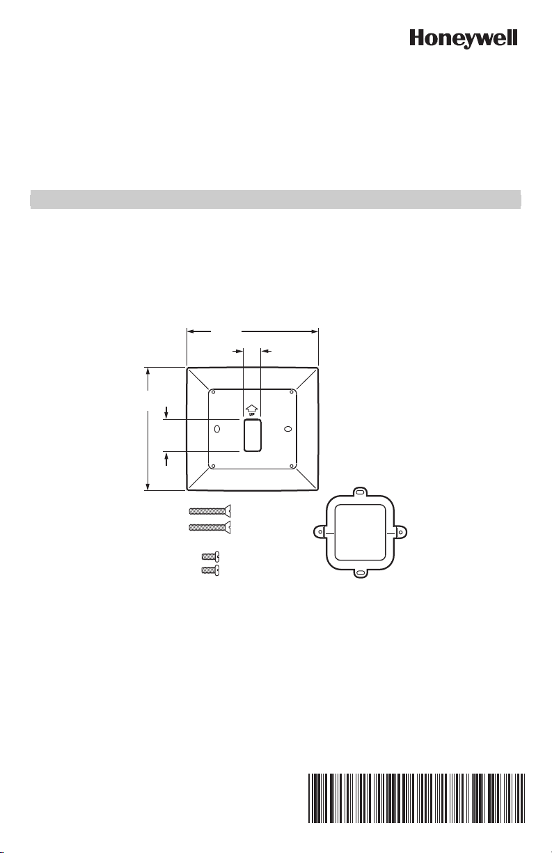
Cover Plate Assembly
INSTALLATION GUIDE
APPLICATION
Use the THP2400A1019 cover plate assembly with the RedLINK™ VisionPRO® thermostats.
Use the THP2400A1019 cover plate assembly to cover marks on the wall or to mount the thermostat to a 2 in. x 4 in.
electrical box.
The THP2400A1019 cover plate assembly contains one cover plate, one bracket, two #6-32 x 5/8 flat head screws and
two #6-32 x 1/4 pan head screws. See Fig. 1.
6-5/32
5-3/4
(146)
1-1/2
(38)
(156)
25/32
(20)
TWO #6-32 X 5/8 FLAT HEAD SCREWS
TWO #6-32 X 1/4 PAN HEAD SCREWS
Fig. 1. THP2400A1019 cover plate assembly.
LEVEL
BRACKET
LEVEL
M34258
INSTALLATION
When Installing this Product…
1. Read these instructions carefully. Failure to follow them could damage the product or cause a hazardous
condition.
2. Check ratings given in the instructions and on the product to make sure the product is suitable for your
application.
3. Installer must be a trained, experienced service technician.
4. After installation is complete, check out product operation as provided in these instructions.
69-2762EFS-01
Page 2
THP2400A1019 COVER PLATE ASSEMBLY
CAUTION
WALL OPENING
WALL ANCHORS (2)
(PROVIDED WITH
THERMOSTAT)
DRILLED HOLES (2)
WALL
MOUNTING SCREWS (2)
(PROVIDED WITH
THERMOSTAT)
M34259
WIRE
WIRE HOLE
COVER PLATE
MOUNTING HOLES (2)
THERMOSTAT
WIRE HOLE
WALL PLATE
MOUNTING HOLES (2)
Electrical Hazard.
Can cause electrical shock or equipment damage.
Disconnect power before beginning installation.
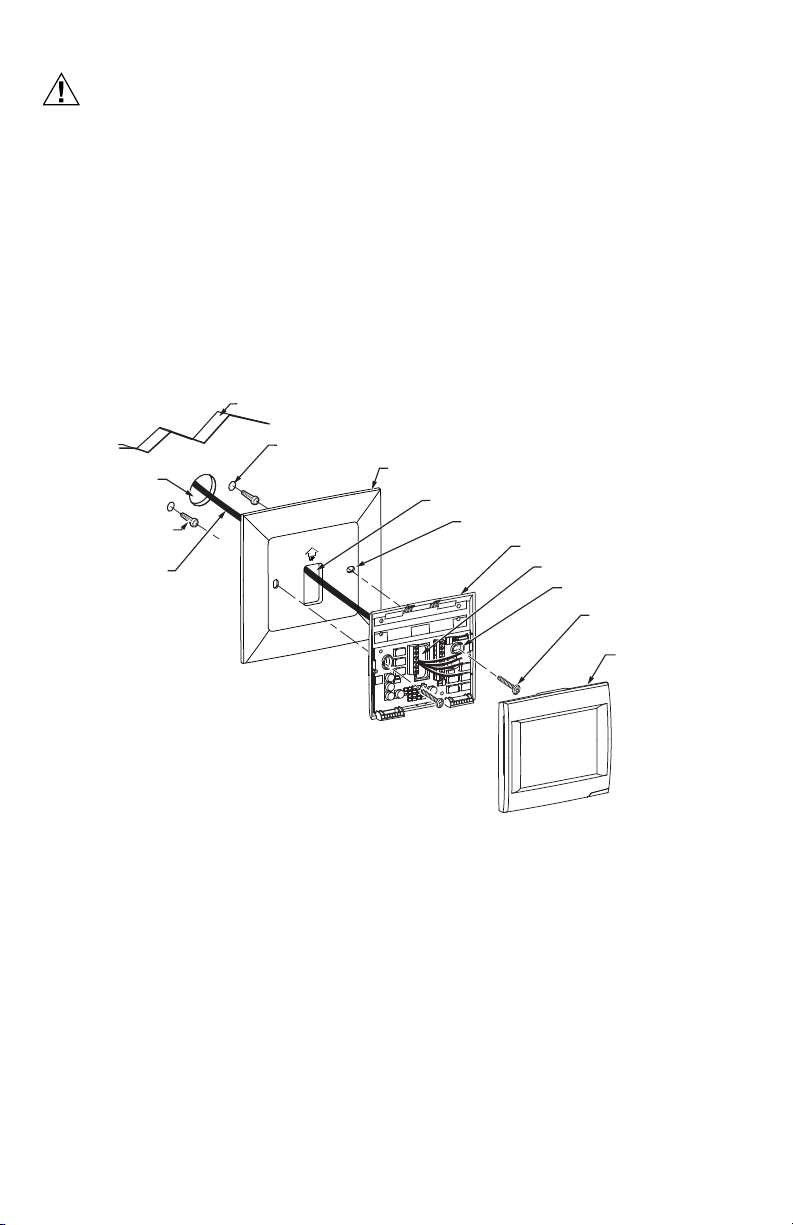
Mount Cover Plate
Mount Cover Plate Directly to Wall (See Fig. 2)
1. Pull the wires through the wire hole on the cover plate and wall plate.
2. Position the cover plate and wall plate on the wall with the arrows pointing up. Level the wall plate for appearance
only.
3. Use a pencil to mark the mounting holes for your thermostat.
4. Remove the cover plate and wall plate from the wall and drill two 3/16-in. holes in the wall (if drywall) as marked.
For firmer material such as plaster, drill two 7/32-in. holes. Tap the wall anchors (provided with the thermostat)
into the holes, until the anchor collar touches the wall.
5. Pull the wires through the wire hole on the cover plate and wall plate. Position the cover plate and wall plate on
the wall anchors.
6. Insert the mounting screws (provided with the thermostat) into the wall anchors. Check leveling, if desired, and
tighten the mounting screws.
Fig. 2. Mount cover plate, wall plate and thermostat directly to wall.
69-2762EFS—01 2
Page 3
THP2400A1019 COVER PLATE ASSEMBLY
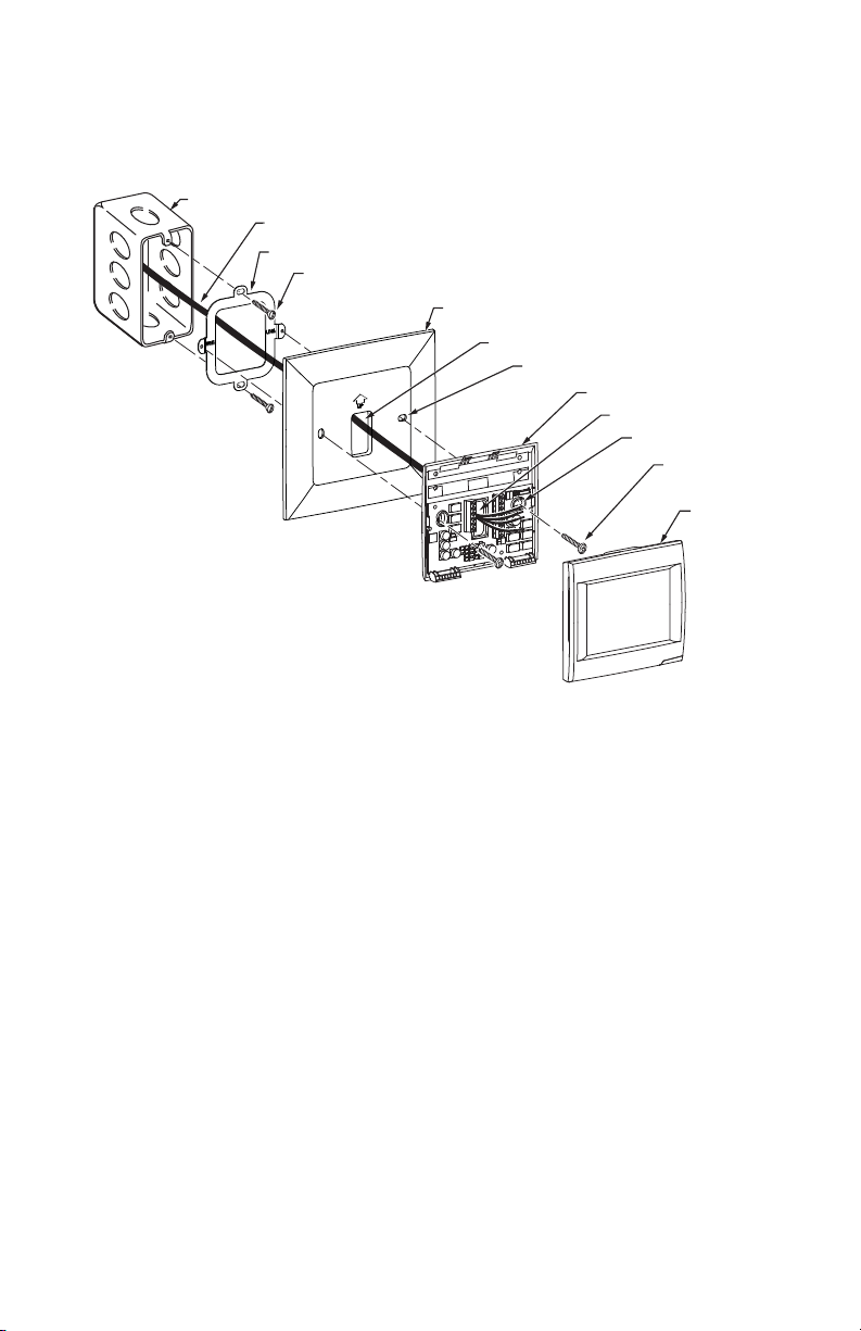
Mount Cover Plate to a Vertical 2 in. X 4 in. Electrical Box (See Fig. 3)
1. Position the bracket on the electrical box. Insert two #6-32 X 5/8 flat head screws. Check leveling, if desired, and
tighten the flat head screws.
2. Pull the wires through the wire hole on the cover plate and wall plate. Position the cover plate and wall plate on
the bracket with the arrows pointing up.
3. Insert two #6-32 X 1/4 pan head screws and tighten.
ELECTRICAL BOX
WIRE
BRACKET
#6-32 X 5/8 FLAT
HEAD SCREWS (2)
COVER PLATE
WIRE HOLE
MOUNTING HOLES (2)
WALL PLATE
WIRE HOLE
MOUNTING HOLES (2)
#6-32 X 1/4 PAN
HEAD SCREWS (2)
THERMOSTAT
M34260
Fig. 3. Mount bracket, cover plate, wall plate and thermostat to a vertical 2 in. X 4 in. electrical box.
3 69-2762EFS—01
Page 4
THP2400A1019 COVER PLATE ASSEMBLY
#6-32 X 5/8 FLAT
HEAD SCREWS (2)
M34261
ELECTRICAL BOX
WIRE
WIRE HOLE
COVER PLATE
MOUNTING HOLES (2)
THERMOSTAT
WIRE HOLE
WALL PLATE
MOUNTING HOLES (2)
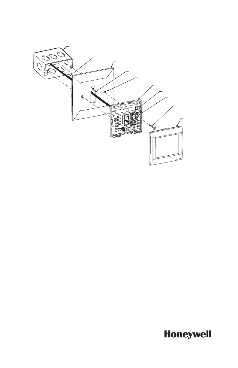
Mount Cover Plate to a Horizontal 2 in. X 4 in. Electrical Box (See Fig 4)
1. Pull the wires through the wire hole on the cover plate and wall plate. Position the cover plate and wall plate on
the electrical box with the arrows pointing up.
2. Insert two #6-32 X 5/8 flat head screws. Check leveling, if desired, and tighten the flat head screws.
Fig. 4. Mount cover plate, wall plate and thermostat to a horizontal 2 in. X 4 in. electrical box.
Automation and Control Solutions
Honeywell International Inc.
1985 Douglas Drive North
Golden Valley, MN 55422
customer.honeywell.com
® U.S. Registered Trademark
© 2012 Honeywell International Inc.
69-2762EFS—01 M.S. 10-12
Printed in United States
Page 5

Ensemble de plaques de
MF34258
DEUX VIS À TÊTE PLATE NO 6-32 X 5/8
DEUX VIS À TÊTE CYLINDRIQUE
BOMBÉE NO 6-32 X 1/4
SUPPORT
LEVEL
LEVEL
20
(25/32)
156
(6-5/32)
38
(1-1/2)
146
(5-3/4)
recouvrement THP2400A1019
GUIDE D’INSTALLATION
APPLICATION
Utiliser l'ensemble de plaques de recouvrement THP2400A1019 avec les thermostats RedLINK™ VisionPRO®.
Utiliser l'ensemble de plaques de recouvrement THP2400A1019 pour couvrir les marques laissées sur le mur ou pour
installer le thermostat dans une boîte électrique de 2 po x 4 po.
L'ensemble de plaques de recouvrement THP2400A1019 contient une petite et une moyenne plaques de
recouvrement, un support, deux vis à tête plate n
la Fig. 1.
o
6-32 x 5/8 et deux vis à tête cylindrique bombée no 6-32 x 1/4. Voir
INSTALLATION
Avant d'installer ce produit...
1. Lire attentivement les instructions. Le fait de ne pas les suivre risque d'endommager le produit ou de constituer
un danger.
2. Vérifier les caractéristiques nominales indiquées dans les instructions et sur le produit, et s'assurer que celui-ci
correspond bien à l'application prévue.
3. L'installateur doit être un technicien d'expérience ayant reçu la formation pertinente.
4. Une fois l'installation terminée, vérifier le fonctionnement du produit comme l'indiquent les présentes instructions.
Fig. 1. Ensemble de plaque de recouvrement THP2400A1019.
Page 6

ENSEMBLE DE PLAQUES DE RECOUVREMENT THP2400A1019
MISE EN GARDE
Risque de choc électrique.
Peut provoquer des chocs électriques ou endommager le matériel.
Couper l'alimentation électrique avant d'effectuer le raccordement.
Installation de la plaque de recouvrement
Installer la plaque de recouvrement directement au mur (voir la Fig. 2)
1. Faire passer les fils par la plaque de recouvrement et la plaque murale.
2. Placer la plaque de recouvrement sur la plaque murale de façon à ce que les flèches pointent vers le haut. Mettre
la plaque murale de niveau (pour l'apparence seulement).
3. Marquer au crayon les ouvertures de montage pour votre thermostat.
4. Retirer la plaque de recouvrement et la plaque murale, puis percer des ouvertures de 3/16 po dans le mur (s'il
s'agit de placoplâtre) aux endroits marqués. Si le mur est d'une matière plus solide, percer deux ouvertures de
7/32 po. Enfoncer doucement les chevilles d'ancrage (fournies avec le thermostat) dans les ouvertures pratiquées dans le mur jusqu'à ce qu'elles affleurent.
5. Faire passer les fils par la plaque de recouvrement et la plaque murale. Placer la plaque de recouvrement et la
plaque murale sur les chevilles.
6. Insérer les vis de fixation (fournies avec le thermostat) dans les chevilles et les resserrer. Vérifier si le thermostat
est au niveau, puis resserrer les vis de fixation.
MUR
OUVERTURES PERCÉES
OUVERTURE
DANS LE MUR
CHEVILLES D’ANCRAGE (2)
(FOURNIES AVEC
LE THERMOSTAT)
FIL
DANS LE MUR (2)
PLAQUE DE RECOUVREMENT
OUVERTURE POUR LES FILS
OUVERTURES DE
FIXATION DANS LE MUR (2)
PLAQUE MURALE
OUVERTURE POUR
LES FILS
OUVERTURES DE FIXATION
DANS LE MUR (2)
VIS DE FIXATION (2)
(FOURNIES AVEC
LE THERMOSTAT)
THERMOSTAT
MF34259
Fig. 2. Installation de la plaque de recouvrement, de la plaque murale et du thermostat directement au mur.
69-2762EFS—01 6
Page 7

ENSEMBLE DE PLAQUES DE RECOUVREMENT THP2400A1019
Installation d'une plaque de recouvrement moyenne sur une boîte électrique de 2
po x 4 po (voir la Fig. 3)
1. Placer le support sur la boîte électrique. Insérer deux vis à tête plate no 6-32 x 5/8. Vérifier si le thermostat est au
niveau, puis resserrer les vis à tête plate.
2. Faire passer les fils par la plaque de recouvrement et la plaque murale. Poser la plaque de recouvrement et la
plaque murale sur le support en faisant pointer les flèches vers le haut.
3. Insérer deux vis à tête cylindrique bombée n
BOÎTE ÉLECTRIQUE
FIL
SUPPORT
VIS À TÊTE PLATE
O
6-32 X 5/8 (2)
N
o
6-32 x 1/4 et resserrer.
PLAQUE DE RECOUVREMENT
OUVERTURE POUR LES FILS
OUVERTURES DE
FIXATION DANS LE MUR (2)
PLAQUE MURALE
OUVERTURE POUR
LES FILS
OUVERTURES DE FIXATION
DANS LE MUR (2)
VIS À TÊTE CYLINDRIQUE
O
6-32 X 1/4 (2)
BOMBÉE N
THERMOSTAT
MF34260
Fig. 3. Installation du support, de la plaque de recouvrement et de la plaque murale sur une boîte électrique de
2 po x 4 po.
7 69-2762EFS—01
Page 8

ENSEMBLE DE PLAQUES DE RECOUVREMENT THP2400A1019
VIS À TÊTE PLATE
N
O
6-32 X 5/8 (2)
MF34261
BOÎTE ÉLECTRIQUE
FIL
OUVERTURE POUR LES FILS
PLAQUE DE RECOUVREMENT
OUVERTURES DE
FIXATION DANS LE MUR (2)
THERMOSTAT
OUVERTURE POUR
LES FILS
PLAQUE MURALE
OUVERTURES DE FIXATION
DANS LE MUR (2)
Installation d'une petite plaque de recouvrement sur une boîte électrique de 2 po x
4 po (voir la Fig. 4)
1. Faire passer les fils par la plaque de recouvrement et la plaque murale. Poser la plaque de recouvrement et la
plaque murale sur le support en faisant pointer les flèches vers le haut.
2. Insérer deux vis à tête plate n
plate.
o
6-32 x 5/8. Vérifier si le thermostat est au niveau, puis resserrer les vis à tête
Fig. 4. Installation de la plaque de recouvrement, et la plaque murale et du thermostat sur une boîte électrique
de 2 po x 4 po.
Solutions de régulation et d’automatisation
Honeywell International Inc.
1985 Douglas Drive North
Golden Valley, MN 55422
customer.honeywell.com
® Marque de commerce déposée aux États-Unis
© 2012 Honeywell Inter national Inc.
Tous droits réservés
69-2762EFS—01 M.S. 10-12
Imprimé aux États-Unis
Page 9

THP2400A1019
MS34258
DOS TORNILLOS CABEZA PLANA No. 6-32 X 5/8
DOS TORNILLOS CABEZA
TRONCOCÓNICA No. 6-32 X 1/4
SOPORTE
LEVEL
LEVEL
25/32
(20)
6-5/32
(156)
1-1/2
(38)
5-3/4
(146)
Conjunto de la placa de
cobertura
GUÍA DE INSTALACIÓN
APLICACIÓN
Utilice el conjunto de la placa de cobertura THP2400A1019 con los termostatos RedLINK™ VisionPRO®.
Utilice el conjunto de la placa de cobertura THP2400A1019 para cubrir marcas en la pared o para instalar el termostato
en un cajetín eléctrico de 2 in. x 4 in. (5,1 cm x 10,2 cm).
El conjunto de la placa de cobertura THP2400A1019 contiene una placa de cobertura, un soporte, dos tornillos cabeza
plana No. 6-32 x 5/8 y dos tornillos cabeza troncocónica No. 6-32 x ¼. Ver Fig. 1.
INSTALACIÓN
Cuando instale este producto...
1. Lea detenidamente estas instrucciones. De no seguirlas se podría dañar el producto o provocar una situación
peligrosa.
2. Verifique los valores nominales especificados en las instrucciones y en el producto para asegurarse de que el
producto sea adecuado para su aplicación.
3. El instalador debe ser un técnico de servicio capacitado y experimentado.
4. Después de terminar la instalación, verifique el funcionamiento del producto tal como se indica en estas instruc-
ciones.
Fig. 1. Conjunto de la placa de cobertura THP2400A1019.
Page 10

THP2400A1019 CONJUNTO DE LA PLACA DE COBERTURA
PRECAUCIÓN
Peligro eléctrico.
Puede causar una descarga eléctrica o daños al equipo.
Desconecte la energía antes de comenzar la instalación.
Monte la placa de cobertura
Monte la placa de cobertura directamente en la pared (Ver Fig. 2)
1. Hale los cables a través del agujero para el cableado en la placa de cobertura y en la placa de pared.
2. Coloque la placa de cobertura y la placa de pared en la pared, con las flechas hacia arriba. Nivele la placa de
pared para fines estéticos únicamente.
3. Marque con un lápiz los orificios de montaje de su termostato.
4. Quite la placa de cobertura y la placa de pared y taladre dos orificios de 3/16 in. (4,8 mm) en la pared (si es panel
de yeso), tal como los marcó. Si el material es más firme, como yeso, taladre dos orificios de 7/32 in. (5,6 mm).
Inserte los anclajes de pared (incluidos con el termostato) en los orificios hasta que queden al nivel de la pared.
5. Hale los cables a través del agujero para el cableado en la placa de cobertura y en la placa de pared. Coloque la
placa de cobertura y la placa de pared sobre los anclajes de pared.
6. Inserte los tornillos de montaje (que se suministran con el termostato) en los anclajes de pared. Verifique la nivel-
ación, si lo desea, y apriete los tornillos de montaje.
PARED
AGUJEROS TALADRADOS (2)
ABERTURA EN
LA PARED
ANCLAJES DE PARED (2)
(SE PROPORCIONAN
CON EL TERMOSTATO)
CABLE
PLACA DE COBERTURA
AGUJERO PARA EL CABLEADO
AGUJEROS DE MONTAJE (2)
PLACA DE PARED
AGUJERO PARA EL CABLEADO
AGUJEROS DE MONTAJE (2)
TORNILLOS DE MONTAJE
(SE PROPORCIONAN
CON EL TERMOSTATO)
TERMOSTATO
Fig. 2. Coloque la placa de cobertura, la placa de pared y el termostato directamente en la pared.
69-2762EFS—01 10
MS34259
Page 11

THP2400A1019 CONJUNTO DE LA PLACA DE COBER TURA
TORNILLOS CABEZA
PLANA No. 6-32 X 5/8 (2)
CAJETÍN ELÉCTRICO
BRACKET
CABLE
AGUJERO PARA EL CABLEADO
PLACA DE COBERTURA
AGUJEROS DE MONTAJE (2)
TORNILLOS CABEZA
TRONCOCÓNICA
No. 6-32 X 1/4 (2)
TERMOSTATO
AGUJERO PARA EL CABLEADO
PLACA DE PARED
AGUJEROS DE MONTAJE (2)
MS34260
Monte la placa de cobertura en un cajetín eléctrico vertical de 2 in. x 4 in. (5,1 cm x
10,2 cm) (Ver Fig. 3)
1. Coloque el soporte en el cajetín eléctrico. Inserte dos tornillos cabeza plana No. 6-32 X 5/8. Verifique la nivel-
ación, si lo desea, y apriete los tornillos cabeza plana.
2. Hale los cables a través del agujero para el cableado de la placa de cobertura y la placa de pared. Coloque la
placa de cobertura y la placa de pared en el soporte con las flechas orientadas hacia arriba.
3. Inserte dos tornillos cabeza troncocónica No. 6-32 X 1/4 y apriete.
Fig. 3. Monte el soporte, la placa de cobertura, la placa de pared y el termostato en un cajetín eléctrico vertical
de 2 in. x 4 in. (5,1 cm x 10,2 cm).
11 69-2762EFS—01
Page 12

THP2400A1019 CONJUNTO DE LA PLACA DE COBERTURA
Monte la placa de cobertura en un cajetín eléctrico horizontal de 2 in. x 4 in. (5,1 cm
x 10,2 cm) (Ver Fig. 4)
1. Hale los cables a través del agujero para el cableado de la placa de cobertura y la placa de pared. Coloque la
placa de cobertura y la placa de pared en el cajetín eléctrico con las flechas orientadas hacia arriba.
2. Inserte dos tornillos cabeza plana No. 6-32 X 5/8. Verifique la nivelación, si lo desea, y apriete los tornillos
cabeza plana.
CAJETÍN ELÉCTRICO
CABLE
Fig. 4. Monte la placa de cobertura, la placa de pared y el termostato en un cajetín eléctrico horizontal de 2 in.
x 4 in. (5,1 cm x 10,2 cm).
PLACA DE COBERTURA
AGUJERO PARA EL CABLEADO
AGUJEROS DE MONTAJE (2)
PLACA DE PARED
AGUJERO PARA EL CABLEADO
AGUJEROS DE MONTAJE (2)
TORNILLOS CABEZA
PLANA No. 6-32 X 5/8 (2)
TERMOSTATO
MS34261
Automatización y control desenlace
Honeywell International Inc.
1985 Douglas Drive North
Golden Valley, MN 55422
customer.honeywell.com
® Marca Registrada e n los Estados Unidos
© 2012 Honeywell Inter national Inc. todos
Los Derechos Reservados
69-2762EFS—01 M.S. 10-12
Impreso en Estados Unidos
 Loading...