

Page 1
Programmable
M29433
MCR29434
FocusPRO
Digital
Thermostat
6000
Installation
Instructions
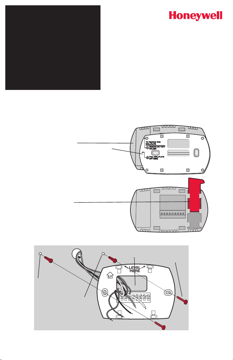
Wallplate installation
Remove the wallplate from the thermostat,
then follow directions below for mounting.
1. Remove battery holder.
2. Pull here to remove wallplate from new
thermostat.
3. Pull wires through wire hole.
4. Position wallplate on wall, level and mark
hole positions with pencil.
5. Drill holes at marked positions as shown
below, then tap in supplied wall anchors.
6. Place wallplate over anchors, insert and
tighten mounting screws.
7. Insert reference card.
®
Series
Drill 3/16"
holes for
drywall.
Drill 7/32"
holes for
plaster.
Wire hole
Mounting
screws
Page 2

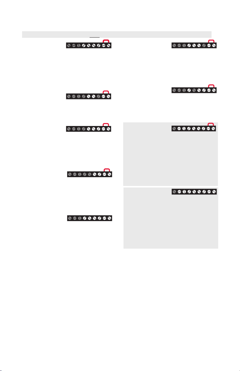
Power options
TH6110D
TH6110D
LR
TH6220D
E
LR
TH6320U
MCR29438A
Keep wires in this
shaded
area
Remove factoryinstalled jumper
only for twotransformer
systems.
Insert batteries for primary
or backup power.
MCR29436
Connect C for primary AC power
(optional if batteries are installed).
Wiring terminal designations
Shaded areas below apply only to TH6320U/TH6220D or as otherwise noted.
Conventional Terminals:
Rc 24VAC power from cooling
transformer
R 24VAC power from heating
transformer
W Heat relay (stage 1)
W2 Heat relay (stage 2)
Y Compressor contactor (stage 1)
Y2 Compressor contactor (stage 2)
G Fan relay
C 24VAC common. For 2 transformer
systems, use common wire from
cooling transformer.
Heat Pump Terminals:
Rc 24VAC power from cooling
transformer
R 24VAC power from heating
transformer
O/B Changeover valve
Y Compressor contactor
Y2 Compressor contactor (stage 2)
-TH6320U only
G Fan relay
Aux/E Auxiliary/Emergency heat relay
L Sends output when set to Em. Heat
C 24VAC common
RcYWGRC
TH6220D
TH6320U
RcYGRC
G
RcYWGW2Y2 RC
RcYWGW2Y2 RC
Aux
E
Y2
C
RcY
RcYGAux
C
2
Page 3
Wiring conventional systems
RcYWGRC
RcWRC
RcYWRC
RcYRC
RcYWG RC
RcWG RC
RcYG RC
RcYWGW2Y2 RC
RcYWGW2Y2 RC
Shaded areas below apply only to TH6320U/TH6220D or as otherwise noted.
1H/1C System
(1 transformer)
Rc Power [1]
R [R+Rc joined by jumper]
Y Compressor contactor
C 24VAC common [3]
W Heat relay
G Fan relay
Heat-only System
Rc Power [1]
R [R+Rc joined by jumper]
C 24VAC common [3]
W Heat relay
Heat-only System
(Series 20) [5]
Rc [R+Rc joined by jumper]
R Series 20 valve terminal “R” [1]
Y Series 20 valve terminal “W”
C 24VAC common [3]
W Series 20 valve terminal “B”
Heat-only System
(normally open zone
valve) [5]
Rc [R+Rc joined by jumper]
R Power [1]
Y Normally open zone valve
C 24VAC common [3]
1H/1C System
(2 transformers)
Rc Power (cooling transformer) [1, 2]
R Power (heating transformer) [1, 2]
Y Compressor contactor
C 24VAC common [3, 4]
W Heat relay
G Fan relay
Heat-only System
with Fan
Rc Power [1]
R [R+Rc joined by jumper]
C 24VAC common [3]
W Heat relay
G Fan relay
Cool-only System
Rc Power [1]
R [R+Rc joined by jumper]
Y Compressor contactor
C 24VAC common [3]
G Fan relay
2H/2C System
(1 transformer) [6]
Rc Power [1]
R [R+Rc joined by jumper]
Y Compressor contactor (stage 1)
C 24VAC common [3]
W Heat relay (stage 1)
G Fan relay
W2 Heat relay (stage 2)
Y2 Compressor contactor (stage 2)
2H/2C System
(2 transformers) [6]
Rc Power (cooling transformer) [1, 2]
R Power (heating transformer) [1, 2]
Y Compressor contactor (stage 1)
C 24VAC common [3, 4]
W Heat relay (stage 1)
G Fan relay
W2 Heat relay (stage 2)
Y2 Compressor contactor (stage 2)
NOTES
Wire specifications:
Use 18- to 22-gauge thermostat wire.
Shielded cable is not required.
[1] Power supply. Provide disconnect means
and overload protection as required.
[2] Remove jumper for 2-transformer systems.
[3] Optional 24VAC common connection.
[4] Common connection must come from cool-
ing transformer.
[5] In Installer Setup, set system type to
Heat Only.
[6] In Installer Setup, set system type to
2Heat/2Cool Conventional.
[7] In Installer Setup, set changeover valve to
O or B.
[8] In Installer Setup, set system type to
2Heat/1Cool Heat Pump.
[9] In Installer Setup, set system type to
2Heat/2Cool Heat Pump.
[10] In Installer Setup, set system type to
3Heat/2Cool Heat Pump.
[11] L terminal sends a continuous output when
thermostat is set to Em. Heat. Connect
to Honeywell zoning panels to switch the
panel to Emergency Heat.
3
Page 4
MCR29453
Rc
E
LR
Rc
E
LR
Rc
LR
Rc
E
LR
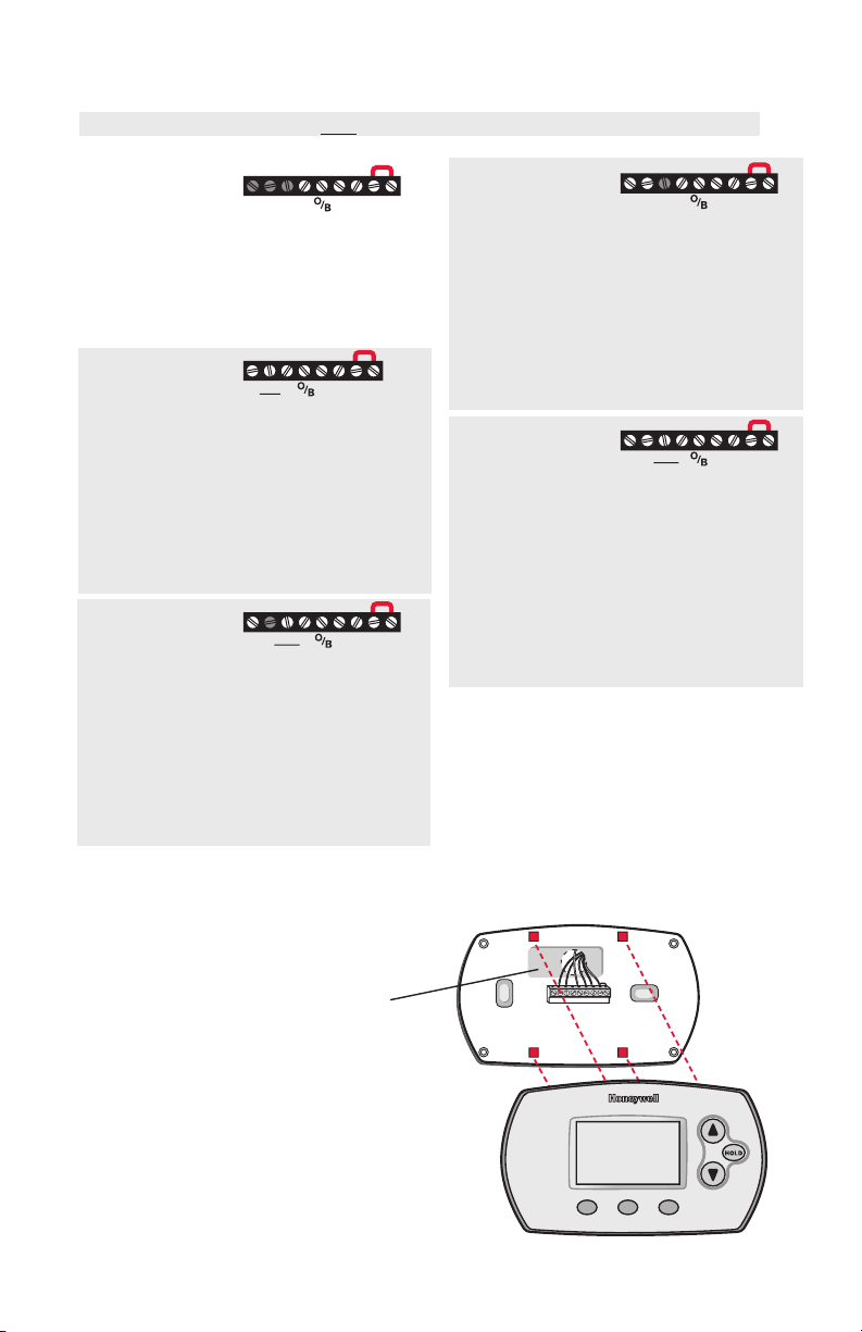
Wiring heat pump systems
Rc
GR
Shaded areas below apply only to TH6320U/TH6220D or as otherwise noted.
1H/1C Heat Pump
Y
System
Rc Power [1]
R [R+Rc joined by jumper]
Y Compressor contactor
C 24VAC common [3]
O/B Changeover valve [7]
G Fan relay
C
2H/1C Heat Pump
System (TH6220D
YGAux
C
only) [8]
Rc Power [1]
R [R+Rc joined by jumper]
Y Compressor contactor
C 24VAC common [3]
O/B Changeover valve [7]
G Fan relay
Aux/E Auxiliary/Emergency heat relay
L Sends output when set to Em. Heat [11]
2H/1C Heat Pump
System (TH6320U
only) [8]
Rc Power [1]
R [R+Rc joined by jumper]
Y Compressor contactor
C 24VAC common [3]
O/B Changeover valve [7]
G Fan relay
Aux/E Auxiliary/Emergency heat relay
L Sends output when set to Em. Heat [11]
YGAux
C
2H/2C Heat Pump
YGY2
System (TH6320U
C
only) [9]
Rc Power [1]
R [R+Rc joined by jumper]
Y Compressor contactor (stage 1)
C 24VAC common [3]
O/B Changeover valve [7]
G Fan relay
Y2 Compressor contactor (stage 2)
L Sends output when set to Em. Heat [11]
3H/2C Heat Pump
System (TH6320U
only) [10]
Rc Power [1]
R [R+Rc joined by jumper]
Y Compressor contactor (stage 1)
C 24VAC common [3]
O/B Changeover valve [7]
G Fan relay
Aux/E Auxiliary/Emergency heat relay
Y2 Compressor contactor (stage 2)
L Sends output when set to Em. Heat [11]
See Notes on page 3.
Y2
YGAux
C
Thermostat mounting
1. Push excess wire back into the
wall opening.
2. Plug wall opening with non-
flammable insulation.
3. Align the 4 tabs on the wallplate
with corresponding slots on the
back of the thermostat.
4. Push gently until the thermostat
snaps in place.
4
Page 5
1
0
Done Next
MCR29454
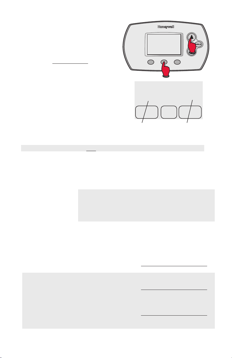
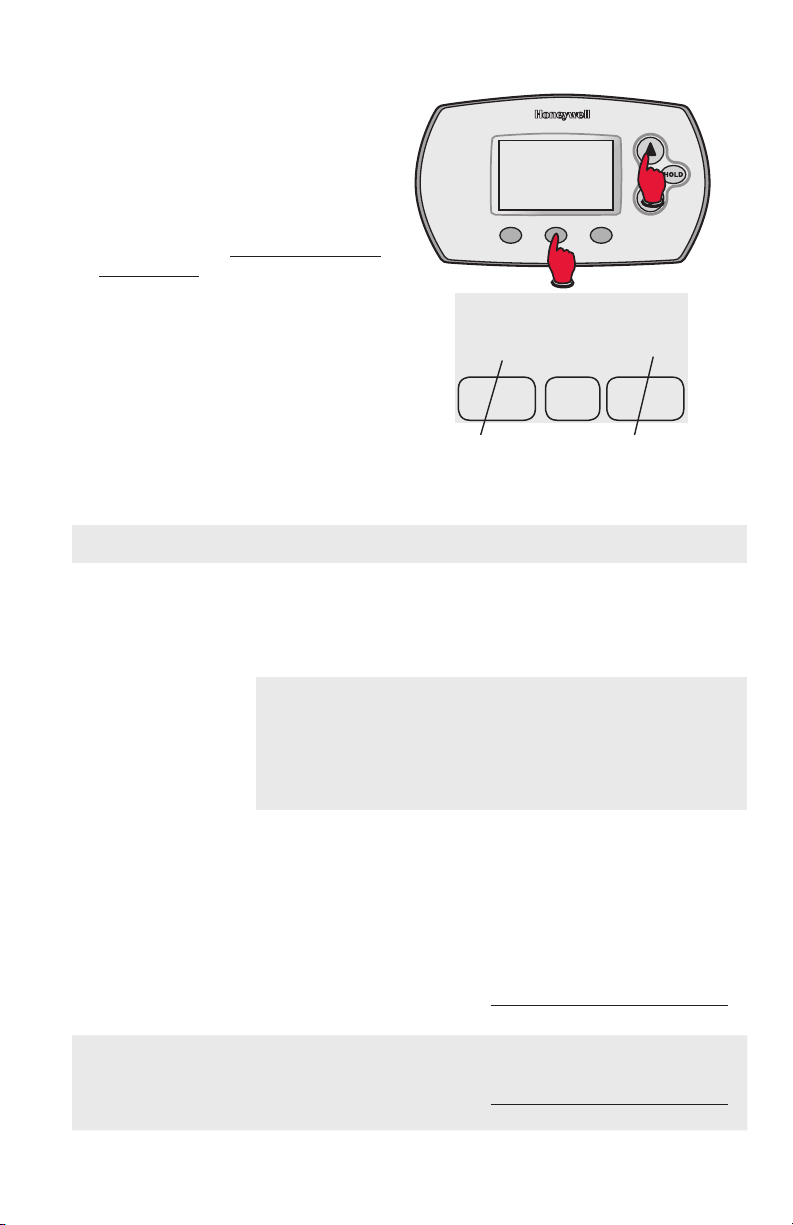
Installer setup
Follow the procedure below to configure
the thermostat to match the installed
heating/cooling system, and customize
feature operation as desired.
1. To begin, press and hold the
and FAN buttons until the display
changes.
2. Press
3. Press NEXT to advance to next
4. Press DONE to exit and save
s or t to change settings.
function.
settings.
s
1
Done Next
0
Function
number
Setting
MCR29454
Setup function Settings & options (factory default in bold)
Shaded areas below apply only to TH6320U/TH6220D or as otherwise noted.
1 System type
2 Changeover valve
(O/B terminal)
3 Fan control
(heating)
5 Stage 1 heat cycle
rate
(CPH: cycles/hour)*
6 Stage 2 heat cycle
rate/Auxiliary heat
cycle rate (CPH)*
7 Auxiliary heat
cycle rate (CPH)*
Only TH6320U
for 3H/2C Heat
Pumps
*[Other cycle rate options: 2, 4, 6, 7, 8, 10, 11 or 12 CPH]
0 1 heat/1 cool conventional
1 1 heat/1 cool heat pump (no aux. heat)
2 Heat only — 2-wire systems, 3-wire zone valves (Series 20),
and normally open zone valves
3 Heat only with fan
4 Cool only
5 2 heat/1 cool heat pump (with aux. heat)
6 2 heat/2 cool conventional
7 2 heat/1 cool conventional
8 1 heat/2 cool conventional
9 2 heat/2 cool heat pump (no aux. heat) - TH6320U only
10 3 heat/2 cool heat pump (with aux. heat) - TH6320U only
0 Changeover valve (O/B terminal energized in cooling)
1 Changeover valve (O/B terminal energized in heating)
0 Gas or oil furnace — equipment controls fan in heating
1 Electric furnace — thermostat controls fan in heating
5 For gas or oil furnaces of less than 90% efficiency
1 For steam or gravity systems
3 For hot water systems & furnaces of over 90% efficiency
9 For electric furnaces
5 For gas or oil furnaces of less than 90% efficiency
1 For steam or gravity systems
3 For hot water systems & furnaces of over 90% efficiency
9 For electric furnaces
5 For gas or oil furnaces of less than 90% efficiency
1 For steam or gravity systems
3 For hot water systems & furnaces of over 90% efficiency
9 For electric furnaces
5
Page 6

Setup function Settings & options (factory default in bold)
Shaded areas below apply only to TH6320U/TH6220D or as otherwise noted.
9 Stage 1 compressor
cycle rate (CPH)
10 Stage 2 compressor
cycle rate (CPH)
12 Manual/Auto
changeover
13 Adaptive Intelligent
Recovery™
14 Temperature
display
15 Compressor
protection
3 Recommended for most compressors
[Other cycle rate options: 1, 2, 4, 5 or 6 CPH]
3 Recommended for most compressors
[Other cycle rate options: 1, 2, 4, 5 or 6 CPH]
0 Manual changeover (Heat/Cool/Off)
1 Auto changeover (Heat/Cool/Auto/Off)
2 Auto changeover only (Auto)
1 On**See page 8
0 Off
0 Fahrenheit
1 Celsius
5 Five-minute compressor off time
[Other options: 0, 1, 2, 3 or 4-minute off time]
16 Schedule format
26 Auxiliary heat
control
27 Heat temperature
range stops
28 Cool temperature
range stops
0 5/2 (programmable weekdays and weekends)
1 5/1/1 (weekdays, Saturday & Sunday programmable)
0 Comfort
1 Economy
90 Max. heat temperature setting is 90 °F (32 °C)
[Other options: 40 °F to 89 °F (4.5 °C to 31.5 °C)]
50 Min. cool temperature setting is 50 °F (10 °C)
[Other options: 51 °F to 99 °F (10.5 °C to 37 °C)]
Special function
Auto Changeover (Setup Function 12): When set to Auto, the thermostat
automatically selects heating or cooling depending on the indoor temperature.
The thermostat will automatically adjust heat and cool settings to maintain
a 3-degree separation (fixed). Note: If you select Auto Changeover Only,
the System Setting on the thermostat will stay locked in the Auto position,
preventing the user from changing it to Em Heat, Heat, Cool or Off.
Adaptive Intelligent Recovery™ (Setup Function 13): Allows the thermostat
to “learn” how long the furnace and air conditioner take to reach programmed
temperature settings, so the temperature is reached at the scheduled time.
Compressor Protection (Setup Function 15): Forces the compressor to wait
a few minutes before restarting, to prevent damage. During the wait time, the
message Cool On or Heat On (heat pumps only) will flash on the display.
6
Page 7

5
10
0
Installer system test
1. To begin, press and hold the
s and t buttons until the
display changes.
2. Press s / t to turn system
on/off.
3. Press NEXT to advance to next
test
4. Press DONE to terminate
system test.
10
System test
number
System test System status
Shaded areas below apply only to TH6320U/TH6220D or as otherwise noted.
10 Heating system
0 Heat and fan turn off.
1 Stage 1 heat turns on. Fan turns on if Setup Function 1 is
set to 1, 5, 9 or 10 OR Setup Function 3 is set to 1
2 Stage 2 heat turns on
3 Stage 3 heat turns on - TH6320U only
0
MCR2945
System
status
20 Emergency heating
system
30 Cooling system
40 Fan system
0 Heat and fan turn off
1 Heat and fan turn on
0 Compressor and fan turn off
1 Compressor and fan turn on
2 Stage 2 compressor turns on
0 Fan turns off
1 Fan turns on
Specifications
Temperature Ranges
Heat: 40° to 90°F (4.5° to 32°C)
Cool: 50° to 99°F (10° to 37°C)
Operating Ambient Temperature
32° to 120°F (0° to 48.9°C)
Shipping Temperature
-20° to 120°F (-28.9° to 48.9°C)
Operating Relative Humidity
5% to 90% (non-condensing)
Physical Dimensions
3-9/16” H x 5-13/16” W x 1-1/2” D
91 mm H x 147 mm W x 38 mm D
Electrical Ratings
Terminal Voltage (50/60Hz) Running Current
W Heating 20-30 Vac 0.02-1.0 A
(Powerpile) 750 mV DC 100 mA DC
W2 (Aux/E) Heating 20-30 Vac 0.02-1.0 A
Y Cooling 20-30 Vac 0.02-1.0 A
Y2 Cooling 20-30 Vac 0.02-1.0 A
G Fan 20-30 Vac 0.02-0.5 A
O/B Changeover 20-30 Vac 0.02-0.5 A
L Output 20-30 Vac 0.02-0.5 A
7
Page 8
69-2695EFS-05
Customer assistance
For assistance with this product, please
visit customer.honeywell.com.
Or call Honeywell Customer Care tollfree at 1-800-468-1502.
CAUTION:
EQUIPMENT DAMAGE HAZARD
Compressor protection is bypassed during testing. To prevent equipment damage, avoid
cycling the compressor quickly.
CAUTION:
ELECTRICAL HAZARD
Can cause electrical shock or equipment damage. Disconnect power before beginning
installation.
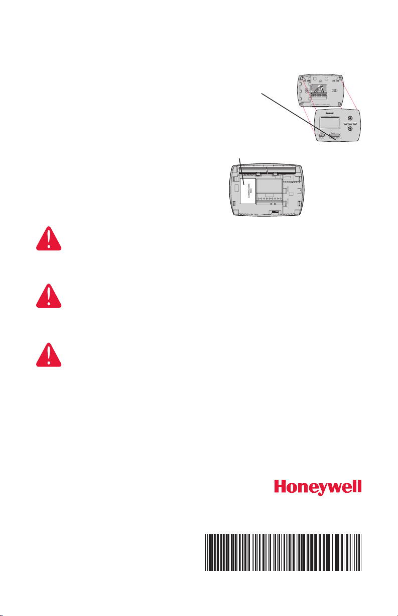
Pull at bottom
to remove
thermostat
from
wallplate.
Turn thermostat
over to find model
number and date
code.
CAUTION:
MERCURY NOTICE
If this product is replacing a control that contains mercury in a sealed tube, do not
place the old control in the trash. Contact your local waste management authority for
instructions regarding recycling and proper disposal.
Automation and Control Solutions
Honeywell International Inc.
1985 Douglas Drive North
Golden Valley, MN 55422
Honeywell Ltd
705 Montrichard Avenue
Saint-Jean-sur-Richelieu, Québec
J2X 5K8
customer.honeywell.com
® U.S. Registered Trademark.
© 2014 Honeywell International Inc.
69-2695EFS— 05 M.S. Rev. 03-14
Printed in U.S.A.
Page 9

Thermostat
M29433
MCR29434
FocusPRO
numérique
programmable
6000 Série
Notice
D’installation
Installation de la plaque murale
Séparer la plaque murale du thermostat
comme, puis suivre les directives
d’installation.
1. Retirer le porte-pile.
2. Tirer ici pour enlever la plaque murale du
thermostat neuf.
3. Faire passer les fils par l’ouverture
réservée aux fils.
4. Placer la plaque murale sur le mur,
mettre de niveau et marquer au crayon
l’emplacement des trous.
5. Percer les trous aux endroits marqués à
l’aide d’une perceuse, puis insérer les
chevilles d’ancrage fournies.
6. Apposer la plaque murale sur les
chevilles, insérer puis resserrer les vis de
fixation.
7. Insérer la carte de référence.
®
Utiliser une
mèche de
3/16 po si le
mur est en
placoplâtre
Utiliser une mèche
de 7/32 po si le
mur est en plâtre.
Trou du fil
Vis de montage
Page 10

Options d’alimentation
TH6110D
TH6220
TH6320
TH6110D
LR
TH6220D
E
LR
TH6320U
MCR29438A
Garder les fils dans
cettezone
ombragée
Enlever le cavalier
installé en usine
uniquement pour
les systèmes
à deux
transformateurs.
Insérer les piles pour l’alimentation
primaire ou de secours.
Brancher C pour l’alimentation
CA primaire (facultatif si des piles
sont installées).
Désignation des bornes
Les zones ombragées ci-dessous s’appliquent seulement au TH6320U/
TH6220D ou selon les indications.
Bornes traditionnelles :
Rc Alimentation de 24 V CA pour
le transformateur de climatisation
R Alimentation de 24 V CA pour
le transformateur de chauffage
W Relais de chauffage (stade 1)
W2 Relais de chauffage (stade 2)
Y Contacteur du compresseur (stade 1)
Y2 Contacteur du compresseur (stade 2)
G Relais de la soufflante
C Neutre 24 V CA Pour les systèmes
à 2 transformateurs, utiliser le neutre
pour le transformateur de climatisation
Bornes de thermopompe :
Rc Alimentation de 24 V CA pour
le transformateur de climatisation
R Alimentation de 24 V CA pour
le transformateur de chauffage
O/B Robinet de substitution
Y Contacteur de compresseur
Y2 Contacteur du compresseur (stade 2)
-TH6320U seulement
G Relais de la soufflante
Aux/E Relais auxiliaire de chauffage/
de chauffage d’urgence
L Envoie le signal de sortie lorsque réglé
à Em. Chauffage
C Neutre 24 V CA
MCR29436
RcYWGRC
D
U
RcYGRC
G
C
RcYWGW2Y2 RC
RcYWGW2Y2 RC
Aux
E
Y2
RcY
C
RcYGAux
2
Page 11

Guide de câblage – systèmes traditionnels
RcYWGRC
RcWRC
RcYWRC
RcYRC
RcYWG RC
RcWG RC
RcYG RC
RcYWGW2Y2 RC
RcYWGW2Y2 RC
Les zones ombragées ci-dessous s’appliquent seulement au TH6320U/
TH6220D ou selon les indications.
Système 1C/1F
(1 transformateur)
Rc Alimentation [1]
R [R+Rc relié par le cavalier]
Y Contacteur de compresseur
C Neutre 24 V CA [3]
W Relais de chauffage
G Relais de la soufflante
Système de chauffage
seulement
Rc Alimentation [1]
R [R+Rc relié par le cavalier]
C Neutre 24 V CA [3]
W Relais de chauffage
Système de chauffage
seulement (Série 20) [5]
Rc [R+Rc reliés par le cavalier]
R Borne de soupape « R » de Série 20 [1]
Y Borne de soupape « W » de Série 20
C Neutre 24 V CA [3]
W Borne de soupape « B » de Série 20
Système de chauffage
seulement (soupape de
zone normalement ouverte) [5]
Rc [R+Rc reliés par le cavalier]
R Alimentation [1]
Y Soupape de zone normalement ouverte
C Neutre 24 V CA [3]
Système 1C/1F
(2 transformateurs)
Rc Alimentation (transformateur de
climatisation) [1, 2]
R Alimentation (transformateur de
chauffage) [1, 2]
Y Contacteur de compresseur
C Neutre 24 V CA [3, 4]
W Relais de chauffage
G Relais de la soufflante
Système de
chauffage seulement
avec soufflante
Rc Alimentation [1]
R [R+Rc reliés par le cavalier]
C Neutre 24 V CA [3]
W Relais de chauffage
G Relais de la soufflante
Système de
climatisation
seulement
Rc Alimentation [1]
R [R+Rc reliés par le cavalier]
Y Contacteur de compresseur
C Neutre 24 V CA [3]
G Relais de la soufflante
Système 2C/2F
(1 transformateur) [6]
Rc Alimentation [1]
R [R+Rc reliés par le cavalier]
Y Contacteur du compresseur (stade 1)
C Neutre 24 V CA [3]
W Relais de chauffage (stade 1)
G Relais de la soufflante
W2 Relais de chauffage (stade 2)
Y2 Contacteur du compresseur (stade 2)
Système 2C/2F
(2 transformateurs) [6]
Rc Alimentation (transformateur de
climatisation) [1, 2]
R Alimentation (transformateur de
chauffage) [1, 2]
Y Contacteur du compresseur (stade 1)
C Neutre 24 V CA [3, 4]
W Relais de chauffage (stade 1)
G Relais de la soufflante
W2 Relais de chauffage (stade 2)
Y2 Contacteur du compresseur (stade 2)
REMARQUES
Spécifications des fils :
Utiliser du fil pour thermostat de calibre 18 à 22. Il
n’est pas nécessaire d’utiliser des câbles blindés.
[1] Alimentation. Procure un moyen de débrancher
et une protection contre la surcharge au besoin.
[2] Retirer le cavalier pour les systèmes à 2
transformateurs.
[3] Connexion facultative au neutre 24 V CA.
[4] La connexion du neutre doit venir du
transformateur de climatisation.
[5] Lors de la configuration, régler le type de
système à Chauffage seulement (Heat Only).
[6] Lors de la configuration, régler le type
de système à Traditionnel 2 chauffages/2
climatisations (2Heat/2Cool Conventional).
[7] Lors de la configuration, régler le type de
système à O ou à B.
[8] Lors de la configuration, régler le type de
système à Thermopompe 2 chauffages/1
climatisation (2Heat/1Cool Heat Pump).
[9] Lors de la configuration, régler le type de
système à Thermopompe 2 chauffages/2
climatisation (2Heat/2Cool Heat Pump).
[10] Lors de la configuration, régler le type de
système à Thermopompe 3 chauffages/2
climatisation (3Heat/2Cool Heat Pump).
[11] La borne L envoie un signal continu lorsque le
thermostat est réglé à Em. Chauffage Brancher
aux panneaux de zones Honeywell pour
commuter le panneau au chauffage d’urgence.
3
Page 12

MCR29453
Guide de câblage – systèmes de thermopompes
RcYGRC
Rc
E
LR
Rc
E
LR
RcYGY2LRC
Rc
E
LR
Les zones ombragées ci-dessous s’appliquent seulement au TH6320U/
TH6220D ou selon les indications.
Système de
thermopompe 1C/1F
Rc Alimentation [1]
R [R+Rc reliés par le cavalier]
Y Contacteur de compresseur
C Neutre 24 V CA [3]
O/B Robinet de substitution [7]
G Relais de la soufflante
Système de
thermopompe 2C/1F
YGAux
C
(TH6220D seulement) [8]
Rc Alimentation [1]
R [R+Rc reliés par le cavalier]
Y Contacteur de compresseur
C Neutre 24 V CA [3]
O/B Robinet de substitution [7]
G Relais de la soufflante
Aux/E Relais auxiliaire de chauffage/
de chauffage d’urgence
L Envoie le signal de sortie lorsque réglé
à Em. Chauffage [11]
2H/1C Heat Pump
System (TH6320U
seulement) [8]
Rc Power [1]
R [R+Rc joined by jumper]
Y Compressor contactor
C 24VAC common [3]
O/B Changeover valve [7]
G Fan relay
Aux/E Auxiliary/Emergency heat relay
L Sends output when set to Em. Heat [11]
YGAux
C
Système de
thermopompe 2C/2F
(TH6320U seulement)
[9]
Rc Alimentation [1]
R [R+Rc reliés par le cavalier]
Y Contacteur du compresseur (stade 1)
C Neutre 24 V CA [3]
O/B Robinet de substitution [7]
G Relais de la soufflante
Y2 Contacteur du compresseur (stade 2)
L Envoie le signal de sortie lorsque réglé
à Em. Chauffage [11]
Système de
thermopompe 3C/2F
(TH6320U seulement)
Y2
YGAux
C
[8]
Rc Alimentation [1]
R [R+Rc reliés par le cavalier]
Y Contacteur du compresseur (stade 1)
C Neutre 24 V CA [3]
O/B Robinet de substitution [7]
G Relais de la soufflante
Aux/E Relais auxiliaire de chauffage/
de chauffage d’urgence
Y2 Contacteur du compresseur (stade 2)
L Envoie le signal de sortie lorsque réglé
à Em. Chauffage [11]
Voir Remarques à la page 3.
Montage du thermostat
1. Repousser le fil en excès dans
l’ouverture dans le mur.
2. Boucher l’ouverture dans le
mur au moyen d’un isolant
ininflammable.
3. Faire correspondre les 4
languettes de la plaque murale
avec les fentes correspondantes
au dos du thermostat.
4. pousser doucement jusqu’à ce
que le thermostat fasse entendre
un déclic.
4
Page 13

Mode de configuration par l’installateur
1
0
Done Next
MCR29454
Suivre les directives ci-dessous pour
configurer le thermostat pour qu’il
corresponde au système de chauffagerefroidissement installé, et pour
personnaliser son fonctionnement.
1. Pour commencer, appuyer sur les
touches s et FAN les maintenir
enfoncés jusqu’à ce que l’affichage
change.
2. Appuyer sur la touche s ou t pour
modifier les réglages.
3. Appuyer sur NEXT pour passer à la
1
fonction suivante.
4. Appuyer sur DONE pour quitter et
enregistrer réglages.
Done Next
Numéro de
fonction
Fonctions Réglage et options (réglages de l’usine en gras)
Les zones ombragées ci-dessous s’appliquent seulement au TH6320U/
TH6220D ou selon les indications.
1 Type de système 0 Traditionnel 1 chauffage/1 climatisation (1 heat/1 cool conventional)
2 Robinet de
substitution (Borne
O/B)
3 Commande
de soufflante
(chauffage)
5 Rythme de
cycle de chauffage
de stade 1 (CPH:
cycles par heure)*
6 Rythme de cycle
de chauffage de
stade 2/rythme de
cycle de chauffage
*[Autres options de rythme de cycle : 2, 4, 6, 7, 8, 10, 11 ou 12 cycles par heure]
auxiliaire (CPH)*
1 Thermopompe 1 chauffage/1 climatisation (aucun chauffage auxiliaire) (1 heat/1
cool heat pump)
2 Chauffage seulement (Heat only) – systèmes à 2 fils, soupapes de zone à 3 fils
(Série 20) et soupapes de zone normalement ouvertes
3 Chauffage seulement avec soufflante (Heat only with fan)
4 Climatisation seulement (Cool only)
5 Thermopompe 2 chauffage/1 climatisation (avec chauffage auxiliaire) (1 heat /1
cool heat pump with aux. heat)
6 Traditionnel 2 chauffage/2 climatisation (2 heat/2 cool conventional)
7 Traditionnel 2 chauffage/1 climatisation (2 heat/1 cool conventional)
8 Traditionnel 1 chauffage/2 climatisations (1 heat/2 cool conventional)
9 Thermopompe 2 chauffage/2 climatisation (aucun chauffage auxiliaire) (2 heat/2
cool heat pump) - TH6320U seulement
10 Thermopompe 3 chauffage/2 climatisation (avec chauffage auxiliaire) (3 heat /2
cool heat pump with aux. heat) - TH6320U seulement
0 Robinet de substitution (Changeover valve) (borne O/B activée
lors de la climatisation)
1 Robinet de su bstitution (Changeover valve) (b orne O/B ac tivée lor s du chauf fage)
0 Fournaise au gaz ou au mazout (Gas or oil furnace) –
l’équipement commande la soufflante durant le chauffage
1 Fournaise électrique – le thermostat co mmande la soufflante durant
le chauf fage
5 Pour systèmes au gaz naturel ou au mazout d’une ef ficacité inférieure à 90 %
1 Pour systèmes à l a vapeur ou gr avitaire s
3 Pour systèmes à l ’eau chaude et systèmes de chauffa ge d’une ef ficacité supérie ure à
90 %
9 Pour fournaises électriques
5 Pour systèmes au gaz naturel ou au mazout d’une ef ficacité inférieure à 90 %
1 Pour systèmes à l a vapeur ou gr avitaire s
3 Pour systèmes à l ’eau chaude et systèmes de chauffa ge d’une ef ficacité supérie ure à
90 %
9 Pour fournaises électriques
5
MCR29454
Réglage
0
Page 14

Fonctions Réglage et options (réglages de l’usine en gras)
Les zones ombragées ci-dessous s’appliquent seulement au TH6320U/
TH6220D ou selon les indications.
7 Rythme de cycle de
chauffage auxiliaire
(CPH)*
Seulement le
TH6320U pour les
thermopompes à
3C/2F
9 Rythme de
cycle de
compresseur de
stade 1 (CPH)
10 Rythme de
cycle de
compresseur de
stade 2 (CPH)
12 Substitution
manuelle/
automatique
13 Adaptive Intelligent
Recovery™
14 Affichage de la
température
15 Protection du
compresseur
16 Format
de l’horaire
26 Commande de
chauffage auxiliaire
27 Crans de la
fourchette de
température de
chauffage
28 Crans de la
fourchette de
température de
climatisation
5 Pour systèmes au gaz naturel ou au mazout d’une ef ficacité inférieure à 90 %
1 Pour systèmes à l a vapeur ou gr avitaire s
3 Pour systèmes à l ’eau chaude et systèmes de chauffa ge d’une ef ficacité supérieure à
90 %
9 Pour fournaises électriques
3 Recommandé pour la plupart des compresseurs
[Autres options de r ythme de cycle : 1, 2, 4, 5 ou 6 CPH]
3 Recommandé pour la plupart des compresseurs
[Autres options de r ythme de cycle : 1, 2, 4, 5 ou 6 CPH]
0 Substitution manuelle (Heat/Cool/Off)
1 Substitution automatique (Heat/Cool/Auto/Off)
2 Substitution automatique seulement (Auto)
1 On **Voir page 8
0 Off
0 Fahrenheit
1 Celsius
5 Désactivation du compresseur de cinq minutes
[Autres options : dé sactivation de 0, 1, 2, 3 ou 4 mi nutes]
0 5/2 (programmation de jours de semaine et de week- ends)
1 5/1/1 (programmation des jours de semaine, du samedi et du dimanche)
0 Confort
1 Économie
90 Réglage maximum de température de chauf fage est 90 °F (32 °C) [Au tres opti ons :
40 °F à 89 °F (4.5 °C à 31.5 °C)]
50 Réglage minimum de température de climatisation est 50 °F (10 °C) [Autres optio ns
: 51 °F à 99 °F (10.5 °C à 37 °C)]
*[Autres options de rythme de cycle : 2, 4, 6, 7, 8, 10, 11 ou 12 cycles par heure]
Fonction spéciale
Substitution automatique (Fonction de configuration 12) : Lorsque réglé à Auto, le thermostat
sélectionne automatiquement le chauffage ou la climatisation selon la température intérieure. Le
thermostat ajuste automatiquement les réglages pour maintenir un écart de 3 degrés (fixe). Remarque :
Si vous sélectionnez Substitution automatique seulement, le réglage du système dans le thermostat
demeurera verrouillé à la position Auto, empêchant l’utilisateur de le changer à Em Heat, Heat, Cool ou
Off.
Adaptive Intelligent Recovery™ (Fonction de configuration 13) : Permet au thermostat « d’apprendre »
combien de temps la fournaise ou le climatiseur prend pour atteindre la température programmée afin que
la température atteigne la température voulue au moment voulu.
Protection du compresseur (Fonction de configuration 15) : Force le compresseur à attendre quelques
minutes avant de redémarrer pour prévenir les dommages. Durant la période d’attente, le message Cool
On ou Heat On (thermopompes seulement) clignotera sur l’affichage.
6
Page 15

Test du système par l’installateur
5
10
0
1. Pour commencer, enfoncer
et tenir les touches s et t
jusqu’à ce que l’affichage
change.
2. Appuyer sur s / t pour
activer ou désactiver le
système.
3. Appuyer sur NEXT pour passer
à l’essai suivant.
4. Appuyer sur DONE pour
terminer l’essai du système.
10
Numéro de test
du système
Test du système État du système
Les zones ombragées ci-dessous s’appliquent seulement au TH6320U/
TH6220D ou selon les indications.
10 Système de
chauffage
20 Système de
chauffaged’urgence
30 Système de
climatisation
40 Système de
soufflante
0 Arrêter le chauffage et la soufflante.
1 Activation du chauffage de stade 1. La soufflante entre en
fonction si la fonction de configuraton 1 est réglée à 1 ou 5
OU si la fonction de configuration 3 est réglée à 1.
2 Activation du chauffage de stade 2
3 Activation du chauffage de stade 3 - TH6320U seulement
0 Arrêter le chauffage et la soufflante.
1 Mise en fonction du chauffage et de la soufflante.
0 Arrêter le chauffage et la soufflante
1 Mise en fonction du compresseur et de la soufflante
2 Activation du compresseur de stade 2
0 Désactivation de la soufflante.
1 Activation de la soufflante.
0
MCR2945
État du
système
Caractéristiques techniques
Gammes de température
Chauffage : 4,5 ° à 32 °C (40 ° à 90 °F)
Refroidissement : 10 ° à 37 °C (50 ° à 99 °F)
Gamme de température ambiante de service
0 ° à 48,9 °C (32 ° à 120 °F)
Température à l’expédition
-28,9 ° à 48,9 °C (-20° à 120 °F)
Humidité relative de service
5 % à 90 % (sans condensation)
Encombrement
3-9/16 po H x 5-13/16 po L x 1-1/2 po P
91 mm H x 147 mm L x 38 mm P
Caractéristiques électriques nominales
Terminal service Tension (50/60Hz) Intensité de
W Chauffage 20-30 V CA 0,02-1,0 A
(Pile) 750 mVCC 100 mA CC
W2 (Aux/E) Chauffage 20-30 Vac 0,02-1.0 A
Y Refroidissement 20-30 V CA 0,02-1,0 A
Y2 Refroidissement 20-30 V CA 0,02-1,0 A
G Soufflante 20-30 V CA 0,02-0,5 A
O/B Substitution 20-30 V CA 0,02-0,5 A
L Sortie 20-30 V CA 0,02-0,5 A
7
Page 16

69-2695EFS-05
Services à la clientèle
Pour obtenir de l’aide avec ce produit,
veuillez consulter le site customer.
honeywell.com.
ou vous adresser aux Services à la
clientèle de Honeywell en composant le
1-800-468-1502.
MISE EN GARDE : RISQUE DE DOMMAGE MATÉRIEL
Le système ne tient pas compte du temps d’arrêt minimal du compresseur pendant
le test par l’installateur. Pour éviter d’endommager le matériel, éviter les cycles de
fonctionnement trop rapides du compresseur.
MISE EN GARDE : RISQUE DE CHOC ÉLECTRIQUE
Peut provoquer des chocs électriques ou endommager le matériel. Couper l’alimentation
électrique avant d’effectuer le raccordement.
Tirer le
thermostat par
le bas pour le
détacher de la
plaque murale.
Retourner le
thermostat pour
trouver le numéro
de modèle et le
code de date.
AVIS SUR LE MERCURE
Si le nouveau thermostat remplace un ancien régulateur contenant un contact à
mercure, ne pas mettre l’ancien régulateur aux poubelles. Communiquer avec le service
local de cueillette des déchets pour obtenir de l’information sur le recyclage ou sur la
bonne façon de disposer d’un ancien régulateur contenant un contact à mercure.
Solutions de régulation et d’automatisation
Honeywell International Inc.
1985 Douglas Drive North
Golden Valley, MN 55422
Honeywell Ltd
705 Montrichard Avenue
Saint-Jean-sur-Richelieu, Québec
J2X 5K8
customer.honeywell.com
® Marque de commerce déposée aux É.-U.
© 2014 Honeywell International Inc.
69-2695EFS— 05 M.S. Rev. 03-14
Imprimé aux États-Unis
Page 17

Termo st ato
M29433
MCR29434
FocusPRO
digital
programable
6000
Instrucciones para
la instalación
Instalación de la placa para pared
Quite la placa para pared del termostato, y
luego siga las instrucciones para el montaje.
1. Extraiga el soporte de la batería.
2. Hale de aquí para quitar la placa para
pared del nuevo termostato.
3. Hale los cables a través del agujero para
los cables.
4. Coloque la placa en la pared, nivele y
marque las posiciones de los agujeros.
5. Realice agujeros en las posiciones
marcadas como se muestra abajo e
introduzca las anclas de expansión con
golpes leves.
6. Coloque la placa para pared sobre las
anclas de expansión, introduzca los
tornillos de montaje y ajústelos.
7. Inserte la tarjeta de referencia.
®
Series
En
tablarroca,
realice
agujeros
de 3/16".
En yeso,
realice
agujeros
de 7/32".
Agujero para
el cable
Tornillos de
montaje
Page 18

Opciones de fuentes de energía
TH6110D
TH6220
TH6320
TH6110D
LR
E
LR
MCR29438A
Mantenga los
cables en
esta área
sombreada
Quite el puente
instalado en la
fábrica sólo en
los sistemas
con dos
transformadores.
Coloque las baterías para suministro
de energía principal o de respaldo.
MCR29436
Conecte C para suministrar corriente CA
(opcional si las baterías están instaladas).
Designación de terminales
Las áreas sombreadas que aparecen abajo sólo se utilizan para los modelos
TH6320U y TH6220D o según se indique.
Terminales convencionales:
Rc 24 V CA desde el transformador
del sistema de refrigeración
R 24 V CA desde el transformador
de la calefacción
W Relé de calor (etapa 1)
W2 Relé de calor (etapa 2)
Y Interruptor automático del compresor
(etapa 1)
Y2 Interruptor automático del compresor
(etapa 2)
G Relé del ventilador
C 24 V CA. Para los sistemas de
2 transformadores, utilice cables
comunes desde el transformador
de la refrigeración.
Terminales de la bomba de calor:
Rc 24 V CA desde el transformador
de la refrigeración
R 24 V CA desde el transformador
de la calefacción
O/B Válvula inversora
Y Interruptor automático del compresor
(etapa 1)
Y2 Interruptor automático del compresor
(etapa 2) (únicamente TH6320U)
G Relé del ventilador
Aux/E Relé de calor auxiliar/de emergencia
L Cuando se fija en Em. Heat, envía
un flujo de aire caliente
C 24 V CA
RcYWGRC
D
U
RcYGRC
TH6220D
G
C
RcYWGW2Y2 RC
Aux
E
RcY
TH6320U
RcYWGW2Y2 RC
Y2
RcYGAux
C
2
Page 19

Cableado: sistemas convencionales
RcYWGRC
RcWRC
RcYWRC
RcYRC
RcYWG RC
RcWG RC
RcYG RC
RcYWGW2Y2 RC
RcYWGW2Y2 RC
Las áreas sombreadas que aparecen abajo sólo se utilizan en el caso de los
modelos TH6320U y TH6220D o según se indique.
Sistema de 1
calentador y 1
refrigerador
(1 transformador)
Rc Electricidad [1]
R [R+Rc unidos por un puente]
Y Interruptor automático del compresor
C 24 V CA [3]
W Relé de calor
G Relé del ventilador
Sistema de calefacción
únicamente
Rc Electricidad [1]
R [R+Rc unidos por un puente]
C 24 V CA [3]
W Relé de calor
Sistema de calefacción
únicamente
(Serie 20) [5]
Rc [R+Rc unidos por un puente]
R Terminal “R” de la válvula de la serie 20 [1]
Y Terminal “W” de la válvula de la serie 20
C 24 V CA [3]
W Terminal “B” de la válvula de la serie 20
Sistema de calefacción
únicamente (válvula de
separación normalmente abierta) [5]
Rc [R+Rc unidos por un puente]
R Electricidad [1]
Y Válvula de separación normalmente abierta
C 24 V CA [3]
Sistema de 1
calentador y 1
refrigerador (2 transformadores)
Rc Electricidad (transformador de
refrigeración) [1, 2]
R Electricidad (transformador de calefacción)
[1, 2]
Y Interruptor automático del compresor
C 24 V CA [3, 4]
W Relé de calor
G Relé del ventilador
NOTAS
Especificaciones del cable:
Use cable para termostato de calibre 18 a 22. No
se requiere cable blindado.
[1] Fuente de alimentación. Proporciona el
medio de desconexión y la protección contra
sobrecargas requeridos.
[2] Para sistemas de 2 transformadores quite el
puente.
[3] Conexión común de 24 V CA opcional.
[4] La conexión común debe provenir del
transformador de refrigeración.
[5] Durante la configuración de instalación, coloque
el tipo de sistema en “Heat Only”.
[6] Durante la configuración de instalación,
coloque el tipo de sistema en
Convencionalde 2 calentadores y 2
refrigeradores.
Sistema de
calefacción
únicamente con
ventilador
Rc Electricidad [1]
R [R+Rc unidos por un puente]
C 24 V CA [3]
W Relé de calor
G Relé del ventilador
Sistema únicamente
de refrigeración
Rc Electricidad [1]
R [R+Rc unidos por un puente]
Y Interruptor automático del compresor
C 24 V CA [3]
G Relé del ventilador
Sistema de 2
calentadores y dos
refrigeradores (1 transformador) [6]
Rc Electricidad [1]
R [R+Rc unidos por un puente]
Y Interruptor automático del compresor
(etapa 1)
C 24 V CA [3]
W Relé de calor (etapa 1)
G Relé del ventilador
W2 Relé de calor (etapa 2)
Y2 Interruptor automático del compresor
(etapa 2)
Sistema de 2
calentadores y dos
refrigeradores (2 transformadores) [6]
Rc Electricidad (transformador de
refrigeración) [1, 2]
R Electricidad (transformador de calefacción)
[1, 2]
Y Interruptor automático del compresor
(etapa 1)
C 24 V CA [3, 4]
W Relé de calor (etapa 1)
G Relé del ventilador
W2 Relé de calor (etapa 2)
Y2 Interruptor automático del compresor
(etapa 2)
[7] Durante la configuración de instalación, coloque
la válvula inversora en la posición O o B.
[8] Durante la configuración de instalación,
coloque el tipo de sistema en Bomba de
calor de 2 calentadores y 1 refri gerador.
[9] Durante la configuración de instalación,
coloque el tipo de sistema en Bomba de
calor de 2 calentadores y 2 refrigeradores.
[10] Durante la configuración de instalación,
coloque el tipo de sistema en Bomba de
calor de 3 calentadores y 2 refrigeradores.
[11] El terminal L envía un flujo continuo de aire
caliente cuando el termostato está en la
posición Em. Heat. Conéctelo a los paneles
de separación de Honeywell para cambiar a
Em. Heat.
3
Page 20

MCR29453
Cableado: sistemas de bomba de calor
Rc
GR
Rc
E
LR
Rc
E
LR
Rc
LR
Rc
E
LR
Las áreas sombreadas que aparecen abajo sólo se utilizan en el caso de los
modelos TH6320U y TH6220D o según se indique.
Sistema de bomba de
Y
calor de 1 calentador y 1
C
refrigerador
Rc Electricidad [1]
R [R+Rc unidos por un puente]
Y Interruptor automático del compresor
C 24 V CA [3]
O/B Válvula inversora [7]
G Relé del ventilador
Sistema de bomba de
YGAux
calor de 2 calentadores y
C
1 refrigerador (únicamente
TH6220D) [8]
Rc Electricidad [1]
R [R+Rc unidos por un puente]
Y Interruptor automático del compresor
C 24 V CA [3]
O/B Válvula inversora [7]
G Relé del ventilador
Aux/E Relé de calor auxiliar/de emergencia
L Cuando se fija en Em. Heat, envía un flujo
de aire caliente [11]
Sistema de bomba de
calor de 2 calentadores
YGAux
C
y 1 refrigerador
(únicamente TH6320U) [8]
Rc Electricidad [1]
R [R+Rc unidos por un puente]
Y Interruptor automático del compresor
C 24 V CA [3]
O/B Válvula inversora [7]
G Relé del ventilador
Aux/E Relé de calor auxiliar/de emergencia
L Cuando se fija en Em. Heat, envía un flujo
de aire caliente [11]
Sistema de bomba
YGY2
de calor de 2
C
calentadores y 2
refrigeradores (únicamente TH6320U) [9]
Rc Electricidad [1]
R [R+Rc unidos por un puente]
Y Interruptor automático del compresor
(etapa 1)
C 24 V CA [3]
O/B Válvula inversora [7]
G Relé del ventilador
Y2 Interruptor automático del compresor
(etapa 2)
L Cuando se fija en Em. Heat, envía un flujo
de aire caliente [11]
Sistema de bomba
de calor de 3
calentadores y
Y2
YGAux
C
2 refrigeradores
(únicamente TH6320U) [10]
Rc Electricidad [1]
R [R+Rc unidos por un puente]
Y Interruptor automático del compresor
(etapa 1)
C 24 V CA [3]
O/B Válvula inversora [7]
G Relé del ventilador
Aux/E Relé de calor auxiliar/de emergencia
Y2 Interruptor automático del compresor
(etapa 2)
L Cuando se fija en Em. Heat, envía un flujo
de aire caliente [11]
Vea las Notas en la página 3.
Montaje del termostato
1. Coloque el excedente de cable
en el interior de la abertura de la
pared.
2. Tape la abertura de la pared con
un aislamiento no inflamable.
3. Alinee las 4 lengüetas de
la placa para pared con las
ranuras de la parte posterior del
termostato.
4. Presione levemente hasta que el
termostato encaje en su lugar.
4
Page 21
Configuración de instalación
1
0
Done Next
MCR29454
Siga el procedimiento que aparece
a continuación para configurar el
termostato a fin de que se corresponda
con el sistema de calefacción y
refrigeración instalado, y seleccione las
funciones según lo desee.
1. Para comenzar, pulse y mantenga
presionados los botones s y FAN
hasta que cambie la pantalla.
2. Presione s o t para cambiar la
configuración.
3. Presione NEXT para avanzar a la
1
siguiente función.
4. Presione DONE para salir y guardar
la configuración.
Done Next
Número
Configuración
de función
Funciones de Configuraciones y opciones (las que vienen
la configuración desde la fábrica aparecen en negrita)
Las áreas sombreadas que aparecen abajo sólo se utilizan en el caso de los
modelos TH6320U y TH6220D o según se indique.
1 Tipo de sistema 0 1 calentador y 1 refrigerador convencional
2 Válvula inversora
(terminal O/B)
1 1 bomba de calor con calentador y 1 refrigerador (sin calor aux.)
2 Sólo calor —sistemas de dos cables, válvulas de separación de tres cables
(serie 20) y válvulas de separación normalmente abiertas
3 Sólo calor con ventilador
4 Sólo frío
5 Bomba de calor con 2 calentadores y 1 refrigerador (con calor aux.)
6 2 calentadores y 2 refrigeradores convencionales
7 2 calentadores y 1 refrigerador convencional
8 1 calentador y 2 refrigeradores convencionales
9 Bomba de calor con 2 calentadores y 2 refrigeradores (sin calor aux.)
únicamente en TH6320U
10 Bo mba de calor con 3 cale ntadore s y 2 refrigeradores (co n calor aux .)
únicamente TH6320U
0 Válvula inversora (terminal O/B con energía durante la refrigeración)
1 Válvula de inversora (terminal O/B con energía durante la calefacción)
0
MCR29454
3 Control del ventilador
(calefacción)
5 Velocidad del ciclo
térmico de la primera
etapa
(CPH: ciclos por hora)*
6 Velocidad de ciclo
térmico/ciclo de calor
auxiliar de la etapa 2
(CPH)*
* [Otras opciones de velocidad de ciclo: 2, 4, 6, 7, 8, 10, 11 ó 12 CPH]
0 Sistemas de calefacción a gas o a aceite (el equipo controla al ventilador
para calefacción)
1 Sistema de calefacción eléctrico (el termostato controla el ventilador para
calefacción)
5 Para sistemas de calefacción a gas o a aceite de menos de un 90% de
efectividad
1 Para sistemas de vapor o de gravedad
3 Para sistemas de agua caliente y sistemas de más de un 90% de efectividad
9 Para sistemas eléctricos
5 Para sistemas de calefacción a gas o a aceite de menos de un 90% de
efectividad
1 Para sistemas de vapor o de gravedad
3 Para sistemas de agua caliente y sistemas de más de un 90% de efectividad
9 Para sistemas eléctricos
5
Page 22

Funciones de Configuraciones y opciones (las que vienen
la configuración desde la fábrica aparecen en negrita)
Las áreas sombreadas que aparecen abajo sólo se utilizan en el caso de los
modelos TH6320U y TH6220D o según se indique.
7 Velocidad de ciclo de
calor auxiliar (CPH)*
Únicamente TH6320U
para sistemas de
bombas de calor de
3 calentadores y 2
refrigeradores
9 Rango de ciclos del
compresor de la etapa 1
(CPH)
10 Rango de ciclos del
compresor de la etapa
2 (CPH)
12 Conversión manual/
automática
13 Adaptive Intelligent
Recovery™
14 Visor de temperatura 0 Fahrenheit
15 Protección
del compresor
16 Formato del
programa
5 Para sistemas de calefacción a gas o a aceite de menos de un 90% de
efectividad
1 Para sistemas de vapor o de gravedad
3 Para sistemas de agua caliente y sistemas de más de un 90% de efectividad
9 Para sistemas eléctricos
3 Recomendado para la mayoría de los compresores
[Otras o pcione s de rango de ciclos: 1, 2, 4, 5 ó 6 CPH]
3 Recomendado para la mayoría de los compresores
[Otras o pcione s de rango de ciclos: 1, 2, 4, 5 ó 6 CPH]
0 Conversión manual (calor/frío/apagado)
1 Conversión automática (calor/frío/automático/apagado)
2 Sólo conversión automática (Auto)
1 Encendido * * Vea la página 8
0 Apagado
1 Celsius
5 Tiempo de apagado de 5 minutos para el compresor
[Otras o pcione s: tiempo d e apagado d e 0, 1, 2, 3 ó 4 minutos]
0 5/2 (programable los días de semana y los fines de semana)
1 5/1/1 (programable los días de semana, sábados y domingos)
26 Control de calor auxiliar 0 Comfort
27 Limitador de rango de
temperatura del sistema
de calefacción
28 Limitador de rango de
temperatura del sistema
de enfriamiento
1 Economía
90 La configuración máxima de temperatura es de 90 °F (32 °C)
[Otras o pcione s: 40 °F a 89 °F (4,5 °C a 31,5 °C)]
50 La configuración mínima de enfriamiento es de 50 °F (10 °C)
[Otras o pcione s: 51 °F a 99 °F (10,5 °C a 37 °C)]
* [Otras opciones de velocidad de ciclo: 2, 4, 6, 7, 8, 10, 11 ó 12 CPH]
Funciones especiales
Conveasor automático (configuración 12): Cuando el sistema está configurado en “Auto”,
el termostato elige automáticamente cuándo calentar o enfriar, dependiendo de la temperatura interior.
El termostato ajustará automáticamente las configuraciones de calor y frío a fin de
mantener una separación de 3 grados (fija). Nota: Si selecciona Auto Changeover Only (sólo
conversión automática), la configuración del termostato permanecerá bloqueada en la posición
“Auto”, de modo que el usuario no pueda cambiarla a Em.Heat, Heat, Cool u Off.
Adaptive Intelligent Recovery™ (Setup Function 13): Allows the thermostat to “learn” how long
the furnace and air conditioner take to (configuración 13): Permite al termostato “saber” cuánto
tiempo requiere el sistema de aire acondicionado para alcanzar las configuraciones de temperatura
programadas a fin de alcanzar la temperatura deseada a la hora programada.
Protección del compresor (configuración 15): Hace que el compresor espere unos minutos
antes de reiniciarse, para prevenir daños. Durante el tiempo de espera, el mensaje Cool On
o Heat On (sólo para las bombas de calor) aparecerá parpadeando en la pantalla del visor.
6
Page 23

Prueba del sistema
5
10
0
1. Para comenzar, pulse y mantenga
presionados los botones s y t
hasta que cambie la pantalla
2. Presione s / t para encender o
apagar el sistema.
3. Presione “NEXT” para avanzar
hacia la próxima prueba.
4. Presione “DONE” para finalizar la
10
prueba del sistema.
Número de prueba
del sistema
Prueba del sistema Estado del sistema
Las áreas sombreadas que aparecen abajo sólo se utilizan en el caso de los
modelos TH6320U y TH6220D o según se indique.
10 Sistema de
calefacción
20 Sistema de
calefacción de
emergencia
30 Sistema de
enfriamiento
40 Sistema del
ventilador
0 El calentador y el ventilador se apagan
1 El calentador de la etapa 1 se enciende. El ventilador se
enciende si la función 1 de la configuración se coloca en 1, 5, 9
o 10, o si la función 3 de la configuración se coloca en 1.
2 El calentador de la etapa 2 se enciende
3 El calentador de la etapa 3 se enciende únicamente en TH6320U
0 El calentador y el ventilador se apagan
1 El calentador y el ventilador se encienden
0 El compresor y el ventilador se apagan
1 El compresor y el ventilador se encienden
2 El compresor de la etapa 2 se enciende
0 El ventilador se apaga
1 El ventilador se enciende
0
MCR2945
Estado del
sistema
Especificaciones
Rangos de temperatura
Calor: De 40 °F a 90 °F (de 4,5 °C a 32 °C)
Frío: De 50 °F a 99 °F (de 10 °C a 37 °C)
Temperatura ambiente de funcionamiento
De 32 °F a 120 °F (de 0 ºC a 48,9 °C)
Temperatura de embalaje
De -20 °F a 120 °F (de -28,9 ºC a 48,9 °C)
Humedad relativa de funcionamiento
5% a 90% (no condensable)
Dimensiones físicas
3-9/16” de altura x 5-13/16” de ancho x
1-1/2” de profundidad
91 mm de altura x 147 mm de ancho x
38 mm de profundidad
Rangos eléctricos
Terminal Voltaje (50/60 Hz) Corriente
W Calefacción 20 a 30 V CA 0,02 a 1,0 A
(Powerpile) 750 mV CC 100 mA CC
W2 (Aux/E) Calefacción 20 a 30 V CA 0,02 a 1,0 A
Y Refrigeración 20 a 30 V CA 0,02 a 1,0 A
Y2 Refrigeración 20 a 30 V CA 0,02 a 1,0 A
G Ventilador 20 a 30 V CA 0,02 a 0,5 A
O/B Conversión 20 a 30 V CA 0,02 a 0,5 A
L Salida 20 a 30 V CA 0,02 a 0,5 A
7
Page 24

69-2695EFS-05
Asistencia al cliente
Para obtener asistencia relacionada
con este producto, visite
customer.honeywell.com.
O comuníquese con el número gratuito
del servicio de atención al cliente,
llamando al 1-800-468-1502.
PRECAUCIÓN: PELIGRO DE DAÑO EN EL EQUIPO
Durante la prueba, se desactiva la protección del compresor. Para evitar daños
en el equipo, no permita que el compresor funcione a velocidades altas.
PRECAUCIÓN: RIESGO ELÉCTRICO
Puede ocasionar descargas eléctricas o dañar el equipo. Desconéctelo de la fuente de
energía antes de comenzar la instalación.
Hale de la
parte inferior
para quitar el
termostato de la
placa para pared.
Gire el termostato
para ver el número
de modelo y el
código de fecha.
AVISO SOBRE EL MERCURIO
En caso de que este producto reemplace a un control que contenga mercurio en tubo
sellado, evite arrojar el viejo control a la basura. Póngase en contacto con la autoridad
local para el manejo de desechos a fin de obtener instrucciones sobre el reciclado y la
correcta eliminación de este tipo de desechos.
Automatización y control desenlace
Honeywell International Inc.
1985 Douglas Drive North
Golden Valley, MN 55422
Honeywell Ltd
705 Montrichard Avenue
Saint-Jean-sur-Richelieu, Québec
J2X 5K8
customer.honeywell.com
® Marca Registrada en los E.U.A
© 2014 Honeywell International Inc.
69-2695EFS— 05 M.S. Rev. 03-14
Impreso en EE. UU.
 Loading...