

Page 1
TH5110D Non-programmable
INSTALLATION INSTRUCTIONS
APPLICATION
The TH5110D Non-programmable Thermostat provides
electronic control of 24 Vac, single-stage heating and
Table 1. TH5110D Thermostat description.
Feature Description
Powering Methods • Battery only
System Types (Up to 1 Heat, 1 Cool) • Gas, oil or electric heat with air conditioning
Changeover Manual or auto changeover selectable
System Setting Heat-Off-Cool-Auto
Fan Setting Auto-On
• Common wire only
• Common wire with battery backup
• Warm air, hot water, high efficiency furnaces, heat pumps, steam
and gravity
• Heat only— includes power to open and power to close zone valves
(Series 20) and normally-open zone valves
• Heat only with fan
• Cool only
• 750 mV heating systems
cooling systems or 750 mV heating systems. See Table 1
for a description.
Thermostat
MERCURY NOTICE
If this control is replacing a control that contains
mercury in a sealed tube, do not place your old
control in the trash.
Contact your local waste management authority
for instructions regarding recycling and the
proper disposal of the old thermostat.
® U.S. Registered Trademark
Copyright © 2004 Honeywell International Inc. • • All Rights Reserved
69-1712—1
Page 2

TH5110D NON-PROGRAMMABLE THERMOSTAT
INSTALLATION
When installing this product…
1. Read these instructions carefully. Failure to follow
these instructions can damage the product or
cause a hazardous condition.
2. Check the ratings given in the instructions and on
the product to make sure the product is suitable for
your application.
3. Installer must be a trained, experienced service
technician.
4. After completing installation, use these instructions
to check out the product operation.
CAUTION
Electrical Hazard.
Can cause electrical shock or equipment
damage.
Disconnect power before beginning installation.
Select Thermostat Location
Select a location for the thermostat about 5ft (1.5m)
above the floor in an area with good air circulation at
average temperature. See Fig. 1.
NO
YES
NO
NO
5 FEET
[1.5 METERS]
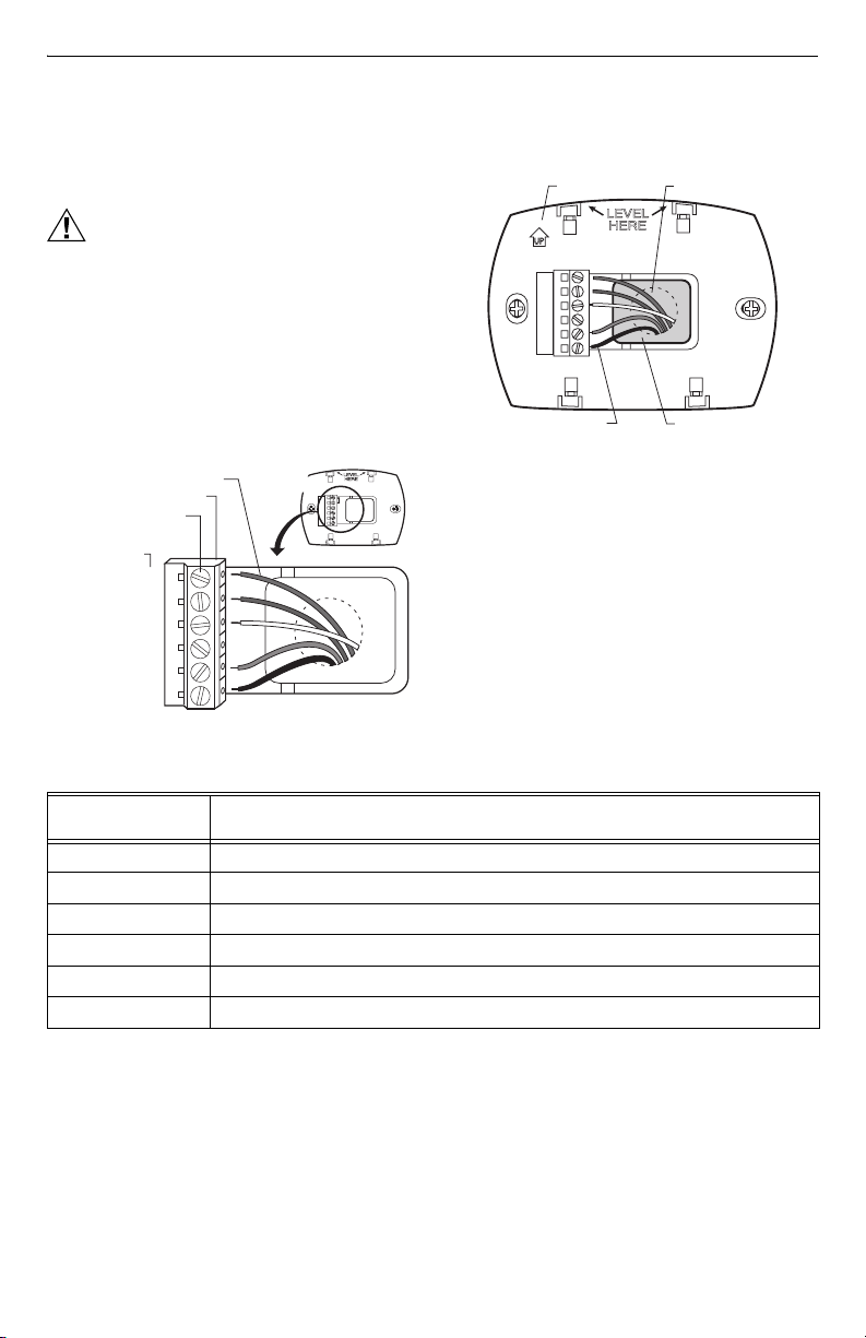
Separate Wallplate from Thermostat
1. Separate the wallplate from the thermostat. See
Fig. 2.
THERMOSTAT
WALLPLATE
WIRE HOLE
M22042
Fig. 2. Separate wallplate from thermostat.
Install Wallplate (See Fig. 3.)
Mount the thermostat horizontally on the wall:
1. Pull the wires through the wire hole on the
wallplate.
2. Position the wallplate on the wall with the arrow
pointing up. Level the wallplate for appearance
only.
3. Use a pencil to mark the mounting holes.
4. Remove the wallplate from the wall and drill
two 3/16-in. holes in the wall (if drywall) as marked.
For firmer material such as plaster, drill two 7/32-in.
holes. Tap the wall anchors (provided) into the
drilled holes until flush with the wall.
5. Pull the wires through the wire hole on the
wallplate and position the wallplate over the wall
anchors.
6. Insert the mounting screws into the wall anchors
and tighten.
M22085
Fig. 1. Select thermostat location.
Do not install the thermostat where it can be affected by:
— Drafts or dead spots behind doors and in corners.
— Hot or cold air from ducts.
— Radiant heat from sun or appliances.
— Concealed pipes and chimneys.
— Unheated (uncooled) areas such as an outside wall
behind the thermostat.
69-1712—1 2
DRILLED HOLES (2)
WALLPLATE
Fig. 3. Install wallplate.
WALL
ANCHORS (2)
R
c
R
Y
C
(O/B)
W
G
MOUNTING
SCREWS (2)
M22140
Page 3
WIRING
TH5110D NON-PROGRAMMABLE THERMOSTAT
All wiring must comply with local electrical codes and
ordinances. Refer to Table 2 for descriptions of terminal
designations. See Fig. 6-13 for wiring diagrams for
specific equipment applications.
2. Push excess wire back into the wall opening and
restrict wires to the shaded area. See Fig. 5.
WALLPLATE
WALL OPENING
CAUTION
Electrical Hazard.
Can cause electrical shock or equipment
damage.
Disconnect power before wiring.
IMPORTANT
Use 18-22 gauge thermostat wire. Shielded
cable is not required.
1. Loosen the screw terminals that are used for the
application. Insert the wires into the terminal block
and tighten each screw terminal. See Fig. 4.
TERMINAL BLOCK
SCREW TERMINALS
LETTER
DESIGNATIONS
O/B W
WIRES
RC
R
Y
C
G
WALLPLATE
RC
R
Y
W/O/B
G
M22141
Fig. 5. Restrict wires to shaded area of wire hole.
3. Plug the wall opening with nonflammable insulation
Fig. 4. Insert wires into terminal block.
Table 2. Terminal designation descriptions.
Terminal
Designation Description
Rc (see Note 1) Power for cooling—connect to secondary side of cooling system transformer
R (see Note 1) Power for heating—connect to secondary side of heating system transformer
Y Compressor contactor
C (see Note 2) Common wire from secondary side of cooling system transformer
O/B W (see Note 3) Heat relay or changeover valve terminal for heat pumps
GFan relay
Rc
R
Y
C
W
(O/B)
G
WIRE
SHADED AREA
to prevent drafts from affecting the thermostat.
M22142
NOTES:
1. When used in a single-transformer system, leave metal jumper in place between Rc and R. If used on a
two-transformer system, remove metal jumper between Rc and R.
2. Common wire is optional when thermostat is used with batteries.
3. If thermostat is configured for a heat pump in the Installer Setup, configure changeover valve
for cool (O-factory setting) or heat (B).
3 69-1712—1
Page 4
TH5110D NON-PROGRAMMABLE THERMOSTAT
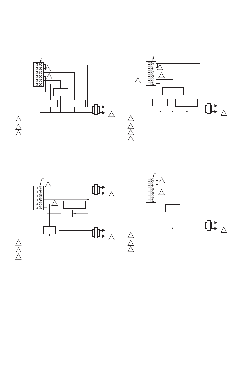
WIRING DIAGRAMS
THERMOSTAT WIRING TERMINALS
Rc
R
2
Y
C
O/B W
POWER SUPPLY. PROVIDE DISCONNECT MEANS AND OVERLOAD
1
PROTECTION AS REQUIRED.
2
FACTORY INSTALLED JUMPER.
OPTIONAL 24 VAC COMMON CONNECTION.
3
Fig. 6. Typical hookup of conventional 1H/1C system
O/B W
POWER SUPPLY. PROVIDE DISCONNECT MEANS AND OVERLOAD
1
PROTECTION AS REQUIRED.
2
REMOVE FACTORY INSTALLED JUMPER.
OPTIONAL 24 VAC COMMON CONNECTION.
3
Fig. 7. Typical hookup of conventional 1H/1C system
3
G
HEAT
RELAY
FAN
RELAY
with one transformer.
THERMOSTAT WIRING TERMINALS
2
Rc
R
Y
C
G
HEAT
RELAY
3
with two transformers.
COMPRESSOR
CONTACTOR
COMPRESSOR
CONTACTOR
FAN
RELAY
R
L1
(HOT)
C
L2
1
M22068
RC
L1
(HOT)
C
L2
1
R
L1
(HOT)
C
L2
1
M22069
THERMOSTAT WIRING TERMINALS
Rc
R
2
Y
C
O/B W
4
POWER SUPPLY. PROVIDE DISCONNECT MEANS AND
1
OVERLOAD PROTECTION AS REQUIRED.
2
FACTORY INSTALLED JUMPER.
OPTIONAL 24 VAC COMMON CONNECTION.
3
CONFIGURE SYSTEM TYPE TO HEAT PUMP AND CHANGEOVER
4
VALVE TO EITHER O OR B IN THE INSTALLER SETUP.
3
G
CHANGEOVER
VALVE
FAN
RELAY
COMPRESSOR
CONTACTOR
R
C
Fig. 8. Typical hookup of 1H/1C heat pump.
THERMOSTAT WIRING TERMINALS
Rc
2
R
Y
C
O/B W
POWER SUPPLY. PROVIDE DISCONNECT MEANS AND
1
OVERLOAD PROTECTION AS REQUIRED.
2
FACTORY INSTALLED JUMPER.
OPTIONAL 24 VAC COMMON CONNECTION.
3
3
G
HEAT
RELAY
R
C
Fig. 9. Typical hookup of heat only system.
L1
(HOT)
L2
M22070
L1
(HOT)
L2
M22071
1
1
69-1712—1 4
Page 5
THERMOSTAT WIRING TERMINALS
Rc
2
R
Y
C
O/B W
POWER SUPPLY. PROVIDE DISCONNECT MEANS AND
1
OVERLOAD PROTECTION AS REQUIRED.
2
FACTORY INSTALLED JUMPER.
OPTIONAL 24 VAC COMMON CONNECTION.
3
3
G
HEAT
RELAY
FAN
RELAY
R
L1
(HOT)
C
L2
1
M22072
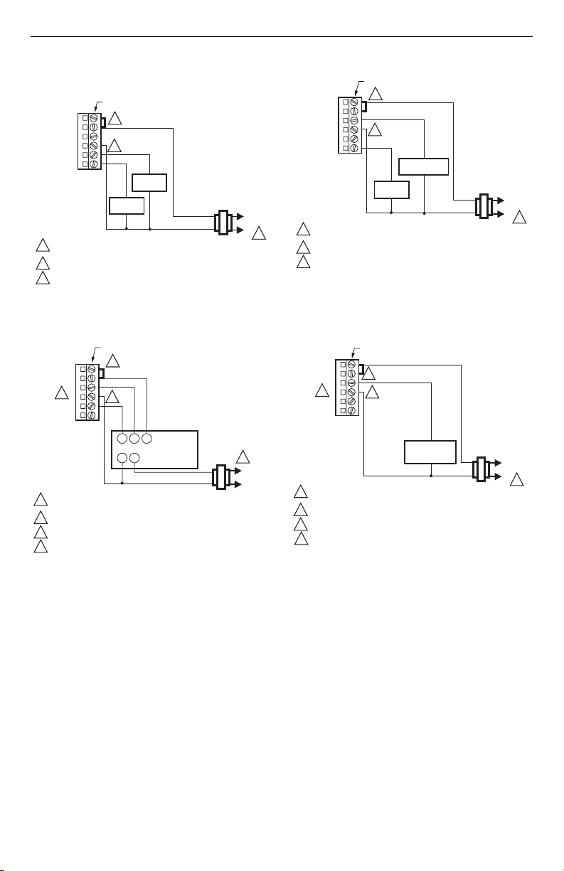
Fig. 10. Typical hookup of heat only system with fan.
TH5110D NON-PROGRAMMABLE THERMOSTAT
THERMOSTAT WIRING TERMINALS
2
Rc
R
Y
C
O/B W
POWER SUPPLY. PROVIDE DISCONNECT MEANS AND
1
OVERLOAD PROTECTION AS REQUIRED.
2
FACTORY INSTALLED JUMPER.
OPTIONAL 24 VAC COMMON CONNECTION.
3
3
G
COMPRESSOR
CONTACTOR
FAN
RELAY
R
C
Fig. 12. Typical hookup of cool only system.
L1
(HOT)
L2
M22074
1
THERMOSTAT WIRING TERMINALS
2
Rc
R
Y
4
C
O/B W
POWER SUPPLY. PROVIDE DISCONNECT MEANS AND
1
OVERLOAD PROTECTION AS REQUIRED.
2
FACTORY INSTALLED JUMPER.
OPTIONAL 24 VAC COMMON CONNECTION.
3
CONFIGURE SYSTEM TYPE TO HEAT ONLY IN THE INSTALLER SETUP.
4
Fig. 11. Typical hookup of heat only Series 20
3
G
POWER TO OPEN
B W R
AND POWER TO
CLOSE
MOTOR OR VALVE
TR TR
(SERIES 20)
R
C
system.
1
L1
(HOT)
L2
M22073
THERMOSTAT WIRING TERMINALS
Rc
R
2
Y
4
C
O/B W
POWER SUPPLY. PROVIDE DISCONNECT MEANS AND
1
OVERLOAD PROTECTION AS REQUIRED.
2
FACTORY INSTALLED JUMPER.
OPTIONAL 24 VAC COMMON CONNECTION.
3
CONFIGURE SYSTEM TYPE TO HEAT ONLY IN THE INSTALLER SETUP.
4
Fig. 13. Typical hookup of a heat only system with a
3
G
NORMALLY
ZONE VALVE
normally open zone valve.
OPEN
R
L1
(HOT)
C
L2
1
M22075
5 69-1712—1
Page 6
TH5110D NON-PROGRAMMABLE THERMOSTAT
POWER THE THERMOSTAT
You can choose from three methods to power the
thermostat:
• Batteries only (AAA alkaline).
• 24 Vac common wire only.
• 24 Vac common wire with battery backup (AAA
alkaline).
NOTE: Battery backup prevents blank displays during
power interruptions.
Wiring 24 Vac Common
• Single-Transformer System—Connect the common
side of the transformer to the C screw terminal of the
thermostat wallplate. Leave the metal jumper in place
between Rc and R.
• Two-Transformer System—Connect the common side
of the cooling transformer to the C screw terminal of
the thermostat wallplate. Remove the metal jumper
between Rc and R.
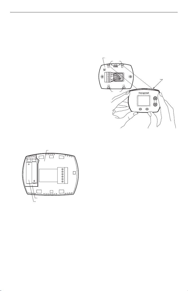
Installing Batteries
Install two AAA alkaline batteries on the back of the
thermostat as marked on the battery holder. See Fig. 14.
NOTE: After the thermostat is mounted on the
wallplate, the thermostat does not require
removal from the wallplate to replace the
batteries. Refer to the enclosed Operating
Instructions, 69-1713, for more information on
the removable battery holder.
BACK OF THERMOSTAT
Mount Thermostat to Wallplate
1. Align the four tabs on the wallplate with the four
slots on the back of the thermostat. Push the
thermostat straight onto the wallplate until it snaps
into place. See Fig 15.
WALLPLATE
TABS
Rc
R
Y
C
W(O/B)
G
TABS
Fig. 15. Mount thermostat to wallplate.
SLOTS ON
BACK OF
THERMOSTAT
M22078
BATTERY HOLDER
BATTERIES
M22056
Fig. 14. Installing batteries.
69-1712—1 6
Page 7

INSTALLER SETUP
Replace Batt
Se
eeded
g
Cool
de
an
o
Cool
System
Replace Batt
Se
eeded
e
t
Replace Batt
Se
eeded
e
t
U
P
Configure Installer Setup
1. Enter Installer Setup by pressing and holding the
Up and Fan buttons, at the same time, for
approximately five seconds, until the screen
changes. See Fig. 16.
Insi
Settin
rvice N
F
Aut
TH5110D NON-PROGRAMMABLE THERMOSTAT
rvice N
Don
Nex
M22143
Fig. 17. Configure Installer Setup.
Fig. 16. Enter Installer setup.
2. Release the Up and Fan buttons when the
display on the thermostat matches the display
in Fig. 17.
M22079
3. See Fig. 18 to review how the thermostat buttons
are used during Installer Setup. See Table 3 for the
Installer Setup Numbers and Settings.
rvice N
Don
Nex
Setup.
SETTING
UP BU
CHANGES SETTING
DOWN BU
CHANGES SETTING
N
EXT BUTTON
ADVANCES TO NEXT
INSTALLER SETUP
NUMBER
TTO
N
TTON
M22144
NSTALLER SET
I
NUMBER
DONE BU
TTON
EXITS THE
INSTALLER SETUP
AND SAVES YOUR SETTINGS
Fig. 18. Review thermostat buttons used for Installer
7 69-1712—1
Page 8

TH5110D NON-PROGRAMMABLE THERMOSTAT
Installer Setup Numbers and Settings
Table 3. Installer setup numbers and settings.
Installer Setup
Number Installer Setup Name Settings
1 System Type 0—gas, oil or electric heat with air conditioning (Factory Setting)
1—Heat pump
2—Heat only (two-wire systems or power to open and power to
close zone valves or normally-open zone valves)
3—Heat only with fan
4—Cool only
2
May not appear.
See Note a
3
May not appear.
See Note b
5
May not appear.
See Note c
9
May not appear.
See Note d
Changeover Valve-O/B
Terminal Energized in
Heating or Cooling
(Heat Pumps only)
Fan Control in Heating 0— Gas or oil furnace— equipment controls fan in heating
Heating Cycle Rate in
cycles per hour (cph)
Compressor Cycle Rate
in cycles per hour (cph)
0—Changeover valve—O/B terminal energized in cooling
(Factory Setting)
1—Changeover valve—O/B terminal energized in heating
(Factory Setting)
1— Electric furnace— thermostat controls fan in heating
5—5 cph used for gas or oil furnaces (less than 90% efficient)
(Factory Setting)
1—1 cph used for steam and gravity
3 —3 cph used for hot water and high efficiency furnaces (90%+)
9—9 cph used for electric furnaces
2, 4, 6, 7, 8, 10, 11, 12—Other cycle rate settings
3—3 cph recommended for compressors (Factory Setting)
1, 2, 4, 5, 6—Other cycle rate settings
12
May not appear.
See Note e
14 Temperature Display 0—Fahrenheit temperature display (Factory Setting)
15
May not appear.
See Note f
Press the Next button to go to the beginning of the Installer Setup or press the Done button to exit the
Installer Setup and save your settings.
Installer Setup Notes:
a—Installer Setup Number 2 does not appear if Installer Setup Number 1 is set to 0, 2, 3 or 4.
b—Installer Setup Number 3 does not appear if Installer Setup Number 1 is set to 1, 2 or 4.
c—Installer Setup Number 5 does not appear if Installer Setup Number 1 is set to 1 or 4.
d—Installer Setup Number 9 does not appear if Installer Setup Number 1 is set to 2 or 3.
e—Installer Setup Number 12 does not appear if Installer Setup Number 1 is set to 2, 3 or 4.
f— Installer Setup Number 15 does not appear if Installer Setup Number 1 is set to 2 or 3.
69-1712—1 8
System Setting
Adjustment
Compressor
Protection—
Minimum-Off Timer in
minutes
0—Manual changeover (Factory Setting) (Heat, Off, Cool)
1—Auto changeover (Heat, Off, Cool, Auto)
2—Auto changeover only (Auto)
1—Celsius temperature display
5—Five-minute compressor off-time setting (Factory Setting)
0, 1, 2, 3, 4—Other compressor off-time settings
Page 9

INSTALLER SYSTEM TEST
Replace Batt
Se
eeded
an
o
Cool
System
Replace Batt
Se
eeded
e
t
Use the Installer System Test to test the heating, cooling
and fan.
CAUTION
Equipment Damage Hazard.
Minimum compressor off time is bypassed
during Installer System Test
Avoid cycling compressor quickly.
How to Use the Installer System Test
1. Enter the Installer System Test by pressing and
holding down the Up and Down buttons at the
same time for approximately five seconds, until the
screen changes. See Fig. 19.
TH5110D NON-PROGRAMMABLE THERMOSTAT
SYSTE
M
TEST
NUMBER
D
ONE BUTTO
EXITS THE INSTALLER
SYSTEM TEST
SYSTE
STATUS
NUMBER
rvice N
Don
N
N
EXT BUTTO
ADVANCES TO NEXT
SYSTEM TEST NUMBER
UP BU
TTO
TURNS THE
SYSTEM ON
TTO
TURNS THE
SYSTEM OFF
N
N
M22146
M
Nex
DOWN BU
N
rvice N
Fig. 20. Review thermostat buttons used during
F
Aut
Installer System Test.
Installer System Tests
IMPORTANT
Use the Installer System Test to test the
heating, cooling and fan. The setting you
choose for System Type (Installer Setup
M22145
Fig. 19. Enter Installer System Test.
2. See Fig. 20 to review how the thermostat buttons
are used during the Installer System Test. See
Table 4 for available Installer System Tests.
Table 4. Installer System Tests.
System Test Number Test Type System Status Number and Description
10 Heating System Test 1—Heat turns on. When Installer Setup Number
30 Cooling System Test 1—Compressor and fan turns on.
40 Fan System Test 1—Fan turns on.
70 Thermostat Information
Press the Next button to go to the beginning of the Installer System Test or press the Done button to exit the
Installer System Test.
(For reference only)
Number 1) may prevent some System Test
Numbers from appearing.
1 is set to 1 or Installer Setup Number 3 is set to
1, the fan turns on immediately.
0—Heat and fan turns off.
0—Compressor and fan turns off.
0—Fan turns off.
71—Software revision number (Major)
72—Software revision number (Minor)
73—Configuration identification code (Major)
74—Configuration identification code (Minor)
75—Production configuration date code (Week)
76—Production configuration date code (Year)
9 69-1712—1
Page 10

TH5110D NON-PROGRAMMABLE THERMOSTAT
Replace Battery
eat
Cool
de
S
g
eat
Sy
m
an
O
o
M
E
LO
D
y
Service Needed
de
Cool
m
an
o
THERMOSTAT OPERATION
Thermostat Buttons and Battery Holder
See Fig. 21 for description of thermostat buttons and
battery holder.
BA
D
IGITAL DISPLAY
Inside
F
a
n
A
u
AN BU
TTO
N
F
SELECTS AUTO OR ON
C
o
S
o
l
e
tti
ng
C
S
o
o
y
l
s
O
to
te
n
m
C
o
o
l
SYSTEM BUTTO
SELECTS HEAT, OFF, COOL OR AUTO
TTERY HOLDER LAT
PRESS TO RELEASE
BATTERY HOLDER
PRESS
N
BA
TTERY
HOLDER
TWO AAA
ALKALINE
BATTERIES
TEMPERATURE
SETTI
NG BU
RAISES
TEMPERATURE
SETTING
TEMPERATURE
NG BU
SETTI
LOWERS
TEMPERATURE
SETTING
CH
TTO
TTO
M22084
N
N
Fig. 21. Review thermostat button description.
Display
See Fig. 22 for description of display.
INSIDE
TE
PERATUR
Insi
F
n Aut
INDICATES BATTERIES ARE
W AND MUST BE REPLACE
ettin
H
ste
H
CURRENT
FAN SETTING
AutoOff
CoolHeat
On
On
Cool
CURRENT
SYSTEM SETTING
TEMPERATURE
SETTING
INDICATES
THERMOSTAT IS
"CALLING" FOR
HEAT OR COOL
M22083
Fig. 22. Review display description.
System and Fan Settings
System
Heat—Thermostat controls the heating system.
Off—Both heating and cooling systems are off.
Cool—Thermostat controls the cooling system.
Auto—Thermostat automatically changes between
heating and cooling operation, depending on indoor
temperature.
Fan
Auto —Fan runs only when the heating or cooling
system is on.
On—Fan runs continuously.
Minimum-Off Timer Compressor Protection
The TH5110 has an adjustable Minimum-Off Timer that
can be set from zero to five minutes (Factory Setting—
five minutes). The Minimum-Off Timer can be bypassed
through the Installer System Test or it can be bypassed
permanently by setting the Minimum-Off Timer to 0
minutes in the Installer Setup.
The Minimum-Off Timer is activated after the compressor
turns off.
If the thermostat is system powered (common wire), the
Minimum-Off Timer is also activated upon initial startup
and after power interruptions.
If there is a call for cooling or heating during the
Minimum-Off Time, the thermostat flashes “Cool On” or
a
“Heat On”
On” or “Heat On”
compressor and fan turn on.
. When the Minimum Off Timer expires, “Cool
a
appears solid in the display and the
______________
a
Heat Pumps only.
Accessories/Replacement Parts
1. Cover Plates (see Fig. 23):
50001137-001 (Small) Cover Plate—
4-5/16 in. (109 mm) high x
5-1/2 in. (140 mm) wide.
50002883-001(Large) Cover Plate—
6 in. (152 mm) high x
8-5/16 in. (211 mm) wide.
M22185
Fig. 23. Cover plate.
2. Replacement Battery Holder (see Fig. 24):
50000951-001 Battery Holder.
BATTERY HOLDER
Insi
F
Replace Batter
Aut
LATCH
Syste
Fig. 24. Battery holder.
BATTERY HOLDER
M22111
69-1712—1 10
Page 11

TH5110D NON-PROGRAMMABLE THERMOSTAT
TROUBLESHOOTING
Table 5. Troubleshooting
Symptom Possible Cause Action
Display is blank. Thermostat is not powered. Check for 24 Vac between Rc and C.
Check that fresh AAA alkaline batteries are
installed as marked on the battery holder.
Temperature settings do
not change.
Heat does not turn on
(Heat On is solid in the
display).
Cooling does not turn on
(Cool On is solid in the
display).
Fan does not turn on in a
call for heat (electric
furnace).
Heat pump puts out cool
air in the heat mode and
warm air in the cool
mode.
Both the heating and
cooling equipment are
running at the same
time.
The highest or lowest temperature
setting was reached.
Heating equipment failure. Check for 24 Vac at the equipment on the
Loose or broken wire connection
between thermostat and heating
equipment.
Cooling equipment failure. Check for 24 Vac at the equipment on the
Loose or broken wire connection
between thermostat and cooling
equipment.
Fan Control in Heating (Installer Setup
Number 3) is set to Gas or Oil Furnace
(Setting 0).
Changeover Valve (Installer Setup
Number 2) is not configured to match the
changeover required by the installed
heat pump.
The heating equipment is not a heat
pump but the System Type (Installer
Setup Number 1) is set to Heat Pump
(Setting 1).
Heating and cooling wires are shorted
together.
Temperat ure setting range:
H e a t i n g : 4 0 ° F t o 9 0 ° F ( 4 . 5 ° C t o 3 2 ° C )
Cooling: 50° F to 99°F (10°C to 37°C)
secondary side of the transformer between
power and common. If voltage is not
present, check the heating equipment to
find the cause of the problem.
Check for 24 Vac between the heat terminal
(W) and transformer common. If 24 Vac is
present, the thermostat is functional. Check
the heating equipment to find the cause of
the problem.
Check for 24 Vac between the heat terminal
(W) and transformer common. If voltage is
not present, check wire connection (loose or
broken) between the thermostat and the
heating equipment.
secondary side of the transformer between
power and common. If voltage is not
present, check the cooling equipment to find
the cause of the problem.
Check for 24 Vac between the cool terminal
(Y) and transformer common. If 24 Vac is
present, the thermostat is functional. Check
the cooling equipment to find the cause of
the problem.
Check for 24 Vac between the cool terminal
(Y) and transformer common. If voltage is
not present, check the wire connection
(loose or broken) between the thermostat
and the cooling equipment.
Set Fan Control in Heating (Installer Setup
Number 3) to Electric Furnace (Setting 1).
Set Changeover Valve (Installer Setup
Number 2) to match the changeover
required by the installed heat pump.
Set System Type (Installer Setup Number 1)
to match the installed heating and/or cooling
equipment.
Separate the shorted heating and cooling
wires.
11 69-1712—1
Page 12

TH5110D NON-PROGRAMMABLE THERMOSTAT
Table 5. Troubleshooting
Symptom Possible Cause Action
Heating equipment is
running in the cool
mode.
Heating equipment does
not turn off and the heat
temperature setting is
set below the room
temperature (Heat On is
not in the display).
Cannot set the system
setting to Heat.
Cannot set the system
setting to Cool.
Heat On is not in the
display.
Cool On is not in the
display.
Heat On is flashing in the
display (Heat pumps
only).
Cool On is flashing in the
display.
Heating equipment is not a heat pump
but System Type (Installer Setup
Number 1) is set to Heat Pump
(Setting 1).
Heating equipment is not a heat pump
but System Type (Installer Setup
Number 1) is set to Heat Pump
(Setting 1).
System Type (Installer Setup Number 1)
is set to Cool Only (Setting 4).
System Setting Adjustment (Installer
Setup Number 12) is set to Auto
Changeover Only (Setting 2).
System Type (Installer Setup Number 1)
is set to Heat Only (Setting 2) or Heat
Only with Fan (Setting 3).
System Setting Adjustment (Installer
Setup Number 12) is set to Auto
Changeover Only (Setting 2).
System setting is not set to Heat and/or
the temperature setting is not set above
the room temperature.
System setting is not set to Cool and/or
the temperature setting is not set below
the room temperature.
Compressor minimum off timer is active. Wait up to five minutes for the heating
Compressor minimum off timer is active. Wait up to five minutes for the cooling
Set System Type (Installer Setup Number 1)
to match the installed heating and/or cooling
equipment.
Set System Type (Installer Setup Number 1)
to match the installed heating and/or cooling
equipment.
Set System Type (Installer Setup Number 1)
to match the installed heating and/or cooling
equipment.
Set System Setting Adjustment (Installer
Setup Number 12) to Manual Changeover
(Setting 0) or Auto Changeover (Setting 1).
Set System Type (Installer Setup Number 1)
to match the installed heating and/or cooling
equipment.
Set System Setting Adjustment (Installer
Setup Number 12) to Manual Changeover
(Setting 0) or Auto Changeover (Setting 1).
Set the system setting to Heat and set the
temperature setting above the room
temperature.
Set the system setting to Cool and set the
temperature setting below the room
temperature.
equipment to turn on.
equipment to turn on.
SPECIFICATIONS
Electrical Ratings:
Terminal
W Heating 20 - 30 Vac .02 - 1.0A
W Heating
(Powerpile)
Y Cooling 20 - 30 Vac .02 - 1.0A
G Fan 20 - 30 Vac .02 - .60A
Automation and Control Solutions
Honeywell International Inc. Honeywell Limited-Honeywell Limitée
1985 Douglas Drive North 35 Dynamic Drive
Golden Valley, MN 55422 Scarborough, Ontario
69-1712—1 J.S. Rev. 6-04 www.honeywell.com/yourhome
Voltage
(50/60 Hz) Running Current
750 mV dc 100 mA dc
M1V 4Z9
Temperature Setting Range:
Heating: 40°F to 90°F (4.5°C to 32°C).
Cooling: 50°F to 99°F (10°C to 37°C).
Operating Ambient Temperature: 37°F to 102°F
(2.8°C to 38.9°C).
Shipping Temperature: -30°F to 150°F
(-34.4°C to 65.6°C).
Operating Relative Humidity (Non-condensing):
5% to 90%.
Thermostat Dimensions: 3-7/16 in (86 mm) high x
4-1/2 in. (114 mm) wide x 1-5/16 in. (33 mm) deep.
 Loading...