

Page 1
Put Bar Code Here
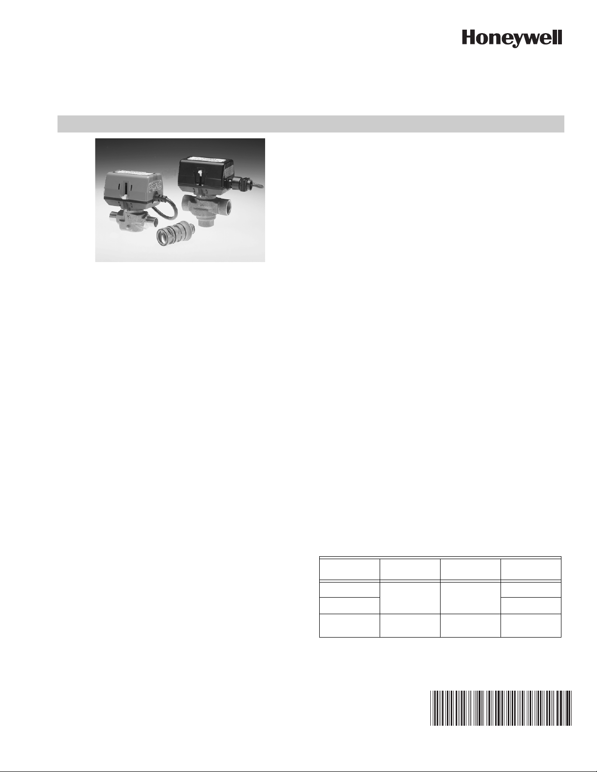
VC7900 Series
Modulating Control Valves
(2) With integral 1 meter (nominal 39") leadwire cable-
VC7931. OR
(3) With intergral 1 meter plenum-rated leadwire cable and 3/8”
flexible conduit connector (low voltage only)- VC7934
VC7934 meets UL94-5V requirements for installation in return
air plenums.
Operating ambient temperature: 0 to 65 °C (32 to 150 °F)
(VC7934 is 60 °C [140 °F] max.)
Shipping & storage temperature: -40 to +65 °C (-40 to
+150 °F)
PRODUCT DATA
The VC7900 Series Modulating Control Valves provide
optimum control of hot and/or chilled water flow in various
heating and cooling applications.
The VC hydronic valve consists of a valve body and
replaceable characterized cartridge assembly. When used with
a Honeywell VC7900 actuator, the valve provides proportional
flow in either diverting or mixing applications. They are
designed to provide sinusoidal valve actuator travel, and
therefore operate silently and resist water hammer. The
VC7900 series valve actuator is used with any 0-10 Vdc
controller.
SPECIFICATIONS
Supply Voltage: Colour coded label
24V, 50-60Hz; Class 2 circuit Blue
Control Signal:
Nominal 0/2 to 10 Vdc (actual 2 to 9 Vdc)
Input impedance 47.5 k ohms
Power consumption: 4 Watts Max. at nominal Voltage (during
valve position change). Use 24 V Class 2 transformer and
provide 6 VA for transformer and connection wire sizing.
Maximum Duty Cycle: 15%
Nominal timing: Opens in 2 minutes @ 60 Hz
Actual Full Stroke Timing is 140 sec
Note: Timing is approximately 20% longer @ 50 Hz
Electrical termination (3 versions available):
(1) Molex™ (header # 39-30-1060). Requires mating connector
(receptacle/housing # 39-01-2060)- VC7930. OR
Atmosphere:
Non-condensing, non-corrosive, non-explosive.
VC7934 meets UL94-5V requirements for installation in return
air plenums.
Min. & max. fluid temperatures: Max. – 4 Bar (60 psi)
Operating pressure differential: Max. – 4 Bar (60 psi)
Pressure rating:
Static – 20 Bar (300 psi)
Burst – 100 Bar (1500 psi)
Valve material: Body of bronze; cartridge of Ryton™
(polyphenylene sulphide) & Noryl™ (polyphenylene oxide);
O-ring seals of EPDM rubber; stainless steel stem.
Flow Characteristics: Linear
The specifications above are nominal and conform to generally
acceptable industry standards. Honeywell is not responsible for
damages resulting from misapplication or misuse of its
products.
Accessories and Replacement Parts:
40007029-002: Wrench for removing VC cartridge
VCZZ1100: 2-way characterized cartridge, unit pack
VCZZ6100: 3-way characterized cartridge, unit pack
Table 1. Series 70, 0/2-10 Vdc Actuator
Model Series
VC7930 24 Vac 120 seconds at
VC7931 1 meter cable
VC7934 24 Vac plenum-
Voltage
(50/60 Hz)
rated
Nominal
Stroke Timing
60 Hz
150 seconds at
50 Hz
Electrical
Connection
6-pin Molex™
1.5 m plenumrated cable
NOTE: Timing is approximately 20% longer @ 50 Hz.
95C-10831-04
Page 2
VC7900 SERIES MODULATING CONTROL VALVES
A
B
3-3/4 (94)
3-9/16
(90)
2-3/4 (68)
C
D
A
B
3-3/4 (94)
3-9/16
(90)
2-3/4 (68)
C
E
D
AB
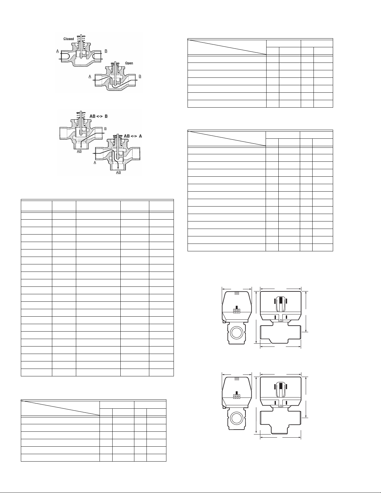
Fig. 1. Fluid flow of 2-way valves
Fig. 2. Fluid flow of 3-way valves
Table 2. Valve Body Models
2-way Valve
Number
AA11xx 3.2 1/2" Sweat MA61xx 3.8
AA15xx 0.7 1/2" Sweat
AA16xx 1.3 1/2" Sweat
AC11xx 2.1 3/8" Flare MB61xx 2.7
AD11xx 3.1 1/2" Flare MC61xx 3.8
AE11xx 3.2 1/2" Inv. Flare MD61xx 4.2
AF11xx 3.0 1/2" BSPP/15mm int ME61xx 3.7
AB11xx 3.4 1/2" BSPT int MN61xx 3.8
AM11xx 4.6 3/4" Sweat ML61xx 5.9
AH11xx 5.2 3/4" BSPP ext MG61xx 6.7
AJ11xx 5.2 3/4" BSPP int MH61xx 6.9
AK11xx 4.7 3/4" BSPT int MJ61xx 6.2
AL11xx 4.7 3/4" NPT int MK61xx 6.6
AG11xx 5.4 22mm Compression* MF61xx 6.9
AP11xx 6.6 1"BSPP int MP61xx 7.5
AQ11xx 6.2 1" BSPP ext MQ61xx 7.9
AS11xx 6.2 1" Sweat MS61xx 6.6
AR11xx 6.6 1" NPT int MR61xx 8.6
AT11xx 6.6 1" BSPT int MT61xx 8.1
AN11xx 6.3 28mm Compression* MM61xx 7.5
BB15xx 0.7 1/2" NPT
BB16xx 1.3 1/2" NPT
CV
Rating Body Fitting
3-way Valve
Number Cv Rating
*Includes compression nuts and olives
Table 3. 2-Way Nominal Dimensions (See Fig. 3)
Dimensions C D
Pipe Fitting Sizes
3/4" BSPP (int. & ext.), 3/4" BSPT (int.) 94 3-11/16 113 4-7/16
3/4" NPT (int.) 94 3-11/16 113 4-7/16
3/4" Sweat 94 3-11/16 113 4-7/16
22 MM* Compression 112 4-7/16 113 4-7/16
1" BSPP (int. & ext.), 1" NPT (int.) 94 3-11/16 113 4-7/16
1" Sweat 94 3-11/16 113 4-7/16
28 MM* Compression 116 4-9/16 113 4-7/16
mm inches mm inches
*Includes compression nuts and olives
Table 4. 3-Way Nominal Dimensions (See Fig. 4)
Dimensions C D
Pipe Fitting Sizes
3/8" Flare (no adapter) 98 3-7/8 136 5-11/32
1/2" Sweat 98 3-7/8 136 5-11/32
1/2" Flare (no adapter) 98 3-7/8 136 5-11/32
1/2" Inverted Flare (no adapter) 98 3 7/8 136 5-11/32
1/2" BSPP (int.), 15 MM Comp. 98 3-7/8 136 5-11/32
1/2" BSPP (int.) 98 3-7/8 136 5-11/32
3/4" BSPP (int.), 3/4" BSPT (int.) 94 3-11/16 130 5-3/32
3/4" BSPP (ext.) 94 3-11/16 130 5-3/32
3/4" NPT (int.) 94 3-11/16 130 5-3/32
3/4" Sweat 94 3-11/16 132 5-3/16
22 MM* Compression 112 4-7/16 140 5-1/2
1" BSPP (int. & ext.), 1" NPT (int.) 94 3-11/16 136 5-11/32
1" Sweat 94 3-11/16 136 5-11/32
28 MM* Compression 116 4-9/16 147 5-13/16
mm inches mm inches
*Includes compression nuts and olives
For example, to order a 120 second stroke timing actuator, with
a 1 meter cable and no auxiliary switch, on a 3-way 3/4” BSPP
internal thread body, you would order VC7931MH6111.
Fig. 3. 2-Way nominal dimensions in inches and
millimeters.
Table 3. 2-Way Nominal Dimensions (See Fig. 3)
Dimensions C D
Pipe Fitting Sizes
3/8" Flare (no adapter) 98 3 -7/8 111 4-3/8
1/2" Sweat 98 3 -7/8 111 4-3/8
1/2" Flare (no adapter) 98 3 -7/8 111 4-3/8
1/2" Inverted Flare (no adapter) 98 3 -7/8 111 4-3/8
1/2" BSPP (int.), 15 MM Comp. 98 3 -7/8 111 4-3/8
1/2" BSPP (int.) 98 3 -7/8 111 4-3/8
95C-10831—04 2
mm inches mm inches
Fig. 4. 3-Way nominal dimensions in inches and
millimeters.
Page 3

INSTALLATION
CAUTION
When Installing This Product...
1. Read these instructions carefully. Failure to follow them
could damage the product or cause a hazardous condition.
2. Check the ratings given in the instructions and on the
product to make sure the product is suitable for your
application.
3. Installer must be a trained, experienced service-person.
4. Always conduct a thorough checkout when installation is
completed.
5. While not necessary to remove the actuator from the
body, it can be removed for ease of installation. The actuator can be installed in any position to suit the most convenient wiring direction. Actuator latching mechanism
works only when the lengths of the actuator and the
valve body are parallel to each other.
6. An extra 25 mm head clearance is required to remove
the actuator.
VC7900 SERIES MODULATING CONTROL VALVES
Put the VC actuator manual lever in the manual open
or the fully open (down) position to allow initial system
flushing with the actuator mounted. This may be done
without electrical hook-up. Alternatively, reusable
flush caps, part # 272866B, may be purchased separately for use in initial flushing of dirty hydronic systems.
Do not use boiler additives, solder flux and wetted
materials which are petroleum based or contain mineral oil, hydrocarbons, or ethylene glycol acetate.
Compounds which can be used, with minimum 50%
water dilution, are diethylene glycol, ethylene glycol,
and propylene glycol (antifreeze solutions).
COMPRESSION MODELS
For compression fitted models, tighten the compression nuts
enough to make a watertight seal. TAKE CARE NOT TO OVER
TIGHTEN. Maximum torque limit is 45 Nm (33 ft-lb) for the
22 mm compression fitting, and 65 Nm (48 ft-lb) for the 28 mm
compression fitting.
1. Disconnect power supply before connecting wiring
to prevent electrical shock and equipment damage.
2. On 24V systems, never jumper the valve coil terminals, even temporarily. This may damage the thermostat.
PLUMBING
The valve may be plumbed in any angle but preferably not with
the actuator below the horizontal level of valve body. Make sure
there is enough room around the actuator for servicing or
replacement.
For use in diverting applications, the valve is installed with the
flow water entering through bottom port AB, and diverting
through end ports A or B. In mixing applications the valve is
installed with inlet to A or B and outlet through AB.
Mount the valve directly in the tube or pipe. Do not grip actuator
while making and tightening up plumbing connections. Either
hold valve body in your hand or attach adjustable spanner
(38 mm or 1-1/2") across the hexagonal or flat faces on the
valve body. (Figure 5).
M29716
Fig. 5. Plumbing of the VC valve.
SWEAT MODELS
On sweat fitted valves, the cartridge is shipped loose to avoid
being damaged during the solder operation.
1. Remove valve actuator from body and solder the connecting pipes in accordance with normal soldering practices.
2. After soldering and valve has cooled, remove cartridge
assembly from plastic bag, insert into the valve body and
tighten down with enclosed wrench (part# 40007029-
002) until it bottoms out. DO NOT OVER TIGHTEN
(maximum torque is 4.5Nm [40 in-lb]). The top surface of
the cartridge will be flush with the top edge of the body
casting.
3. Replace valve actuator.
TO INSTALL REPLACEMENT ACTUATOR
IMPORTANT
Installation of a new actuator does not require draining the system provided the valve body and valve cartridge assembly remain in the pipeline.
1. Check replacement part number and voltage ratings for
match with old device.
2. Disconnect power supply before servicing to avoid electrical shock or equipment damage.
3. Disconnect leadwires to actuator, or depress tab on
Molex™ connector and remove. Where appropriate,
label wires for rewiring.
4. The actuator head is automatically latched to the valve.
To remove, press up on the latch mechanism located
directly below the white manual open lever with thumb
(See Figure 6). Simultaneously press the actuator down
towards the body with moderate hand force and turn the
actuator counter-clockwise by 1/8 turn (45 degrees). Lift
actuator off the valve body.
IMPORTANT
For trouble-free operation of the product, good installation practice must include initial system flushing,
chemical water treatment, and the use of a 50 micron
(preferably 5 micron) 10% side stream system filter(s).
Remove all filter(s) before flushing. Limit flow through
the filter to 5~10% of total system flow to prevent
'starving' the system. Ensure filter cartridge is
changed frequently enough to prevent clogging.
NOTE: The actuator can also be installed at right
angles to the valve body but in this position the
latch mechanism will not engage.
5. Install the new actuator by reversing the process in (4).
6. Reconnect leadwires or Molex™ connector.
7. Restore power, and check out operation.
3 95C-10831—04
Page 4

VC7900 SERIES MODULATING CONTROL VALVES
2
OPERATIONS
WITH SERIES 70, 0/2 - 10 VDC CONTROLLER
(refer to Fig. 7)
In the VC7900, an electronic circuit compares the voltage of
the feedback potentiometer to the signal voltage. If they are
different, then the circuit closes the appropriate triac and
drives the motor in the direction that will bring the circuit back
into balance. In addition, the standard limit switches maintain
the travel to the normal operating range.
Fig. 6. Latch Mechanism to detach Actuator
MANUAL OPENER
The manual opener can be manipulated only when in the up
position. The motorized valve can be opened by firmly
pushing the white manual lever down to midway and in. In this
position both the “A” and “B” ports are open, and with auxiliary
switch models the switch is closed. This "manual open"
position may be used for filling, venting, or draining the
system, or for opening the valve in case of power failure. The
valve can be restored manually to the closed position by
depressing the white manual lever lightly and then pulling the
lever out. The valve and actuator will return to the automatic
position when power is restored.
NOTE: If the valve is powered open, it can not be manually
closed unless actuator is removed.
WIRING
See figures 7A and 7B for single unit wiring details.
Multiple valves may be connected in parallel to a single
controller and transformer, up to the current rating of the
controller and transformer.
In a direct acting model, 2 V signal will be fully closed, and 9 V
will be fully open. In a reverse acting model, 9 V is closed and
2 V is open. However, because of the soft close off of the VC
valve, initial (and final) movements of the actuator will not
cause any significant changes in the valve stem position.
On a loss of power, the actuator will remain in the last
position, and will resume normal operation on power up. On
loss of signal, a direct acting device will go to the closed
default position. A reverse acting device will go to the open
default position.
Fig. 8. Wiring Schematic of the VC7900 Series Actuator
SERVICE
This valve should be serviced by a trained, experienced
service technician.
Fig. 7a.Connector Pin Configuration for Molex™ Models
for 0-10 Vdc Controller (Series 70)
Fig. 7b. Wiring Colour Code for Cable Models for 0-10 Vdc
Controller (Series 70)
Automation and Control Solutions
Honeywell International Inc.
1985 Douglas Drive North
Golden Valley, MN 55422
customer.honeywell.com
® U.S. Registered Trademark
© 2011 Honeywell International Inc.
95C-10831—04 T.D. Rev. 02-11
Printed in U.S.A.
1. If the valve is leaking, drain system OR isolate valve
from the system. Do not remove body from plumbing.
2. Check to see if the cartridge needs to be replaced.
3. If the motor or other internal parts of the actuator is
damaged, replace the entire actuator assembly.
NOTE: Honeywell hydronic valves are designed and tested
for silent operation in properly designed and installed
systems. However, water noises may occur as a
result of excessive water velocity. Piping noises may
occur in high temperature (over 212°F [100°C]) systems with insufficient water pressure.
CHECKOUT
1. Raise the set point of the thermostat above room tem-
perature to initiate a call for heat.
2. Observe all control devices - 2 way valve should open.
Port A in 3 way valve should open, and port B should
close.
3. Lower the set point of the zone thermostat below room
temperature.
4. Observe the control devices. 2 way valve should close.
Port A in 3 way valve should close, and port B should
open.
 Loading...