

Page 1

Put Bar Code Here
Direct Drive Damper Actuator
M847D
INSTALLATION INSTRUCTIONS
APPLICATION
The M847D is a two position, 24 Vac spring return damper
actuator designed to operate directly driven zone dampers,
used to control air flow in ducts. The synchronous motor
actuator can be driven open (or closed) using any 24 volt
rated two position switch - e.g. a wall switch or a thermostat
subbase switch.
The M847D replaces the RDMH and RDMZ damper actuators
for use on Trol-A-Temp® ARD and ZD dampers.
SPECIFICATIONS
Electrical Rating: 24 Vac 60 Hz 0.32 Amp., 8 VA
Electrical Connection: 1/2” conduit
Nominal Angular Rotation: 90° (max. 105°)
Tor que: Min. 423 mNm* (60 in. oz) output torque available
when motor is energized and device is at the spring
returned initial start position.
Nominal Motor Timing: ( @ 25° C ambient)
Energized at rated load - 30 seconds.
De-energized (spring return) - 10 seconds.
Ambient Temperature Rating: 5 to 60° C (+40 to 140° F)
Finish: zinc plated steel, anodized aluminium
Direction of Shaft Rotation: clockwise, when energized and
viewed from the base or shaft end.
Mounting Means: direct connection to damper shaft.
Mounting Position: Multi-poise.
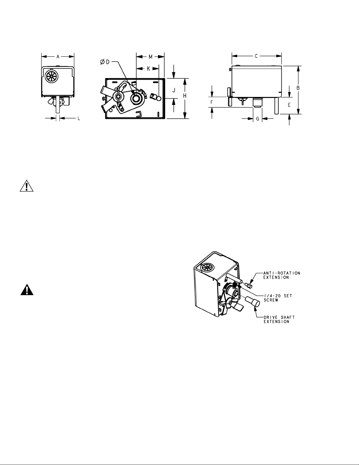
Dimensions: See Figure 1.
*mNm = milli newton meter.
mm
in
mm
in
Table 1. Nominal Device Dimension
ABCDEF
60 84.5 88 8.2 31.5 19.3
2-3/8 3-3/8 3-1/2 5/16 1-1/4 3/4
GHJ K LM
15.8 58.6 29.3 33.5 6.4 40.4
5/8 2-5/16 1-3/16 1-5/16 1/4 1-9/16
95C-10905-02
Page 2
DIRECT DRIVE DAMPER ACTUATOR M847D
CAUTION
WARNING
Fig. 1. Dimensional Details.
INSTALLATION AND CHECKOUT
1. Read these instructions carefully. Failure to follow them
could cause a hazardous condition.
2. Disconnect power supply before beginning of installation and wiring of control to prevent electrical shock or
equipment damage.
3. Check the ratings given in the instructions and on the
product to make sure the product is suitable for your
application.
4. All wiring must comply with local electrical codes, ordinances, and regulations.
5. Installer must be a trained, experienced service technician.
6. After installation is complete, check out the product
operation as provided in these instructions.
1. DO NOT install this actuator on a flue damper.
2. DO NOT attempt to rotate the actuator by turning
the connection coupling or the damper shaft when it
is connected to the actuator or damage to the gear
train may occur.
3. Observe that the damper blades are in the normal,
spring open or spring closed position.
4. Place the new motor onto the shaft and tighten the coupling.
5. Reconnect the motor wiring.
ALTERNATE MOUNTING (For 7/16” dia. coupling style
dampers)
Before installing the M847D actuator to a damper with a 7/16”
coupling, insert the drive shaft extension into the drive shaft
and tighten with the set screw provided. See Fig. 2. Also
install the anti-rotation extension to the end of the anti-rotation
rod. Install the actuator on the damper and tighten the
coupling screw.
STANDARD MOUNTING (For 5/16” dia. damper shaft)
The M847D can be attached directly to the protruding 5/16”
diameter damper shaft using the sleeve of the output shaft.
Drill a 5/16” (8 mm) hole 1-5/16” (33.5 mm) directly below the
damper shaft opening to accept the anti-rotation shaft
protruding from the base of the motor. The length of the
damper shaft to which the connection coupling is attached is
such as to firmly hold the actuator in a position to adequately
engage the anti-rotation pin in the warm air duct. See Figure 1
for the critical dimensions.
Replacing M847D on a Trol-A-Temp® ARD damper
1. Disconnect the motor wiring.
2. Using a 1/8 in. hex wrench to loosen the motor coupling
from the blade shaft, remove the existing motor assembly.
95C-10905—02 2
Fig. 2. For 7/16” Coupling Models Only.
Replacing M847D on a Trol-A-Temp® ZDS or ZDB damper
1. Disconnect the motor wiring.
2. Using a 3/16 in. hex wrench to loosen the Allen screw
located above the faceplate at the motor coupling.
3. Remove the existing motor.
4. Observe that the damper blades are in the open posi-
tion with the setscrew pointing toward the damper label.
5. Attach the new motor to the coupling. Make sure that
the standoff on the motor is positioned in the grommet
on the faceplate.
6. Tighten the set screw.
7. Reconnect the motor wiring.
Page 3

DIRECT DRIVE DAMPER ACTUATOR M847D
Wiring
See Figure 3 for typical wiring hook-ups of the M847D.
1
24 VAC
60 HZ
PROVIDE DISCONNECT MEANS AND OVERLOAD PROTECTION AS REQUIRED.
1
2
NOMINAL CURRENT 0.32 AMP.
ZONING SWITCH
ORANGE
YELLOW
2
OPERATOR
MOTOR
M32381
Fig. 3. Typical M847D Hookup.
CHECKOUT
After completing the installation, check that the equipment
operates correctly as follows:
1. When 24 Vac is applied to the motor leads, the motor
powers to the closed or open position.
2. When power is removed, the motor releases and spring
returns to the normal position.
If full opening and closing is not achieved, check the lower
adjustment lever is to the extreme left and the upper lever is to
the extreme right. See Fig. 4 (Air Flow Adjustments).
1. When viewed on end, the lower lever is normally positioned to the extreme left (See Fig. 4). This position
allows the damper to fully open 90° when de-energized.
2. To restrict the air flow in the open position, loosen (do
not removed) the wing nut and move the lower lever to
the right until the desired position is reached. Tighten
the wing nut. In the extreme right position the damper
should open approx. 50° with the power off.
3. The upper lever is normally positioned to the right to
provide complete shut off when the actuator is energized (See Fig. 4).
4. If desired, to prevent complete closure of the damper,
loosen (do not remove) the wing nut on the bottom of
the unit and move the upper lever to the left until the
desired position is achieved. Tighten the wing nut. In the
extreme left position the damper should close to approx.
40° with the power on.
5. If additional rotation is required beyond 90°, an additional 15° may be obtained by removing the Upper
Lever. To do this, first remove the actuator from the
damper. Remove the wing nut and retaining ring then
remove the levers. Reassemble and install.
Air Flow Adjustments
NOTE: The following describes the adjustments available
with the actuator installed in the power closed
mode. If the damper you are installing is to operate in
the power open mode, the function of the upper and
lower levers is reversed.
Fig. 4. Air Flow Adjustment
3 95C-10905—02
Page 4

DIRECT DRIVE DAMPER ACTUATOR M847D
Automation and Control Solutions
Honeywell International Inc.
1985 Douglas Drive North
Golden Valley, MN 55422
customer.honeywell.com
® U.S. Registered Trademark
© 2010 Honeywell International Inc.
95C-10905—02 T.D. Rev. 12-10
Printed in U.S.A.
 Loading...