


Installation and Assembly:
Paramount™ Flat and Tilt Wall Mount
for LCD and Plasma Flat Panel Screens
Product is UL rated for screen size
range and load capacity per chart below
Model# Screen size range Max UL Load Capacity
PFT640 23" - 46" 100 lb (45 kg)
PFT660 37" - 60" 175 lb (79 kg)
This product is intended for use with UL
R
Listed products and must be installed by a
qualified professional installer.
Features:
• Built-in flat and fixed-tilt feature
• Incremental tilt of 0°, 2°, 5° and 10°
1 of 27
Visit the Peerless Web Site at www.peerlessmounts.com
3215 W. North Ave. • Melrose Park, IL 60160 • (800) 865-2112 or (708) 865-8870 • Fax: (708) 865-2941 • www.peerlessmounts.com
For customer care call 1-800-865-2112 or 708-865-8870.
ISSUED: 05-17-07 SHEET #: 202-9208-3 5-7-08
Note: Read entire instruction sheet before you start installation and assembly.
WARNING
• Do not begin to install your Peerless product until you have read and understood the instructions and warnings
contained in this Installation Sheet. If you have any questions regarding any of the instructions or warnings, please
call Peerless customer care at 1-800-865-2112.
• This product should only be installed by someone of good mechanical aptitude, has experience with basic building
construction, and fully understands these instructions.
• Make sure that the supporting surface will safely support the combined load of the equipment and all attached hardware and components.
• Never exceed the Maximum UL Load Capacity. See page one.
• If mounting to wood wall studs, make sure that mounting screws are anchored into the center of the studs. Use of an
"edge to edge" stud finder is highly recommended.
• Always use an assistant or mechanical lifting equipment to safely lift and position equipment.
• Tighten screws firmly, but do not overtighten. Overtightening can damage the items, greatly reducing their holding
power.
• This product is intended for indoor use only. Use of this product outdoors could lead to product failure and personal injury.
• This product was designed and intended to be mounted to the following supporting surfaces checked below with the
hardware included in this product as specified in the installation sheet. To mount this product to an alternative supporting surface, contact Peerless customer care at 1 800 865-2112.
• This product was designed to be installed on the following wall construction only;
WALL CONSTRUCTION ADDITIONAL HARDWARE REQUIRED
x Wood Stud None
x Wood Beam None
x Solid Concrete None
x Cinder Block None
Metal Stud Do not attach except with Peerless accessory kit for metal studs;
Contact Customer Service for Peerless accessory kit for metal studs.
Brick Contact Customer Service
Other or unsure? Contact Customer Service
Tools Needed for Assembly
• stud finder ("edge to edge" stud finder is recommended)
• phillips screwdriver
• drill
• 1/4" bit for concrete and cinder block wall
• 1/2" bit for metal stud wall
• 5/32" bit for metal or wood stud wall
• level
Accessories
• 4 piece Metal Stud Fastener Kit (ACC 415) (Metal Stud
not evaluated by UL)
• 2 piece Metal Stud Fastener Kit (ACC 215) (Metal Stud
not evaluated by UL)
Table of Contents
Parts List .............................................................................................................................................................................. 3
Installation to Double Wood Stud Wall ..................................................................................................................................4
Installation to Triple Wood Stud Wall .................................................................................................................................... 5
Installation to Solid Concrete or Cinder Block ....................................................................................................................... 6
Installing Vertical Brackets ................................................................................................................................................... 7
Installing Flat Panel Screen to Wall Plate............................................................................................................................. 9
For customer care call (800) 865-2112 or (708) 865-8870.
ISSUED: 05-17-07 SHEET #: 202-9208-3 5-7-08
Visit the Peerless Web Site at www.peerlessmounts.com
2 of 27
For customer care call 1-800-865-2112 or 708-865-8870.
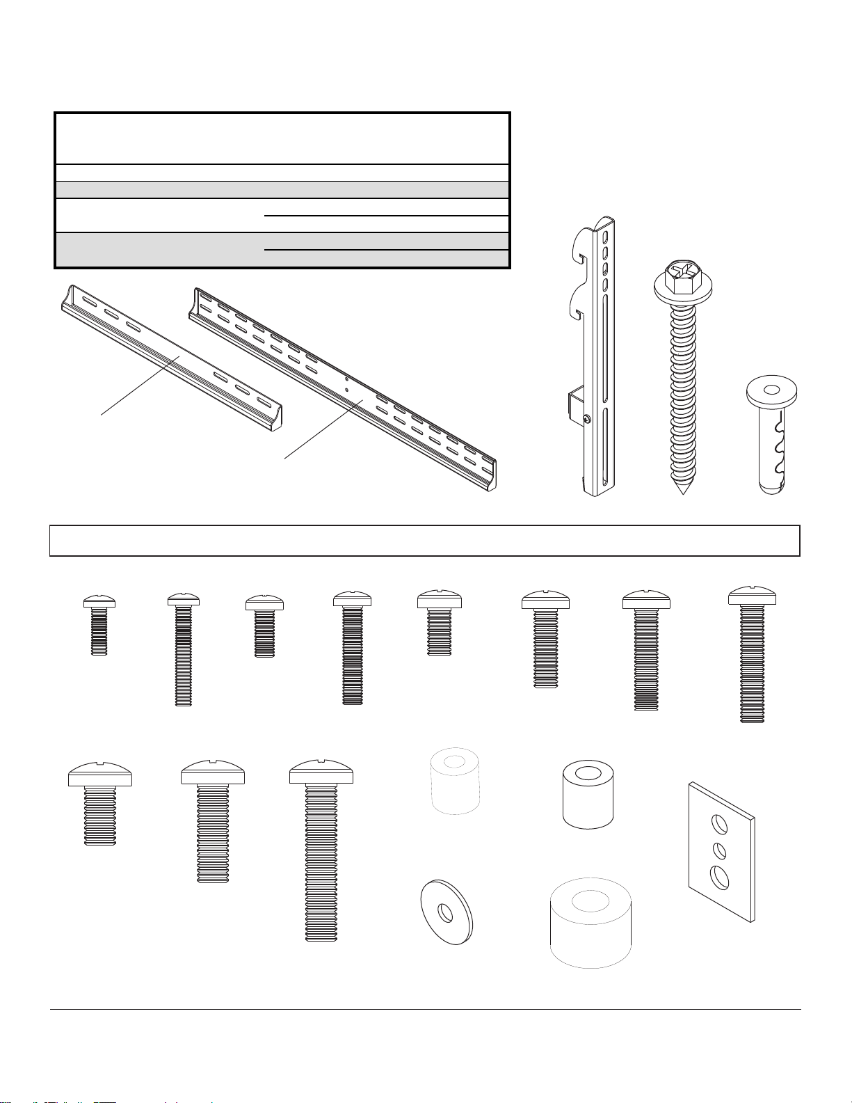
Before you begin, make sure all parts shown are included with your product.
PFT640 PFT660
Description Qty. Part # Part #
A
wall plate 1
201-P1300 201-P1311
B
vertical bracket 2
201-0370 201-0371
C
#14 x 2.5" wood screw 4
5S1-015-C03
6
5S1-015-C03
D
alligator® anchor 4
590-0097
6
590-0097
Parts List
Parts may appear slightly different than illustrated.
A
PFT640
WALLPLATE
A
PFT660
WALLPLATE
BC
D
Adapter Bracket Fasteners
Note: The sorted-for-you™ fastener pack included was made specifically for your product and may not contain all components
shown below.
M4 x 12 mm
504-9013
M4 x 25 mm
504-1015
M8 x 16 mm
520-9257
M8 x 25 mm
520-1031
Visit the Peerless Web Site at www.peerlessmounts.com
M5 x 12 mm
520-1027
M5 x 25 mm
520-9543
M8 x 40 mm
520-1136
M6 x 12 mm
520-1128
I.D. 5.6 mm
540-1057
I.D. 5.1 mm
540-1040
3 of 27
M6 x 20 mm
520-9402
I.D. 6.5 mm
540-1058
I.D. 8.7 mm
540-1059
ISSUED: 05-17-07 SHEET #: 202-9208-3 5-7-08
For customer care call 1-800-865-2112 or 708-865-8870.
M6 x 25 mm
520-1208
M6 x 30 mm
510-9109
multi-washer
580-1036

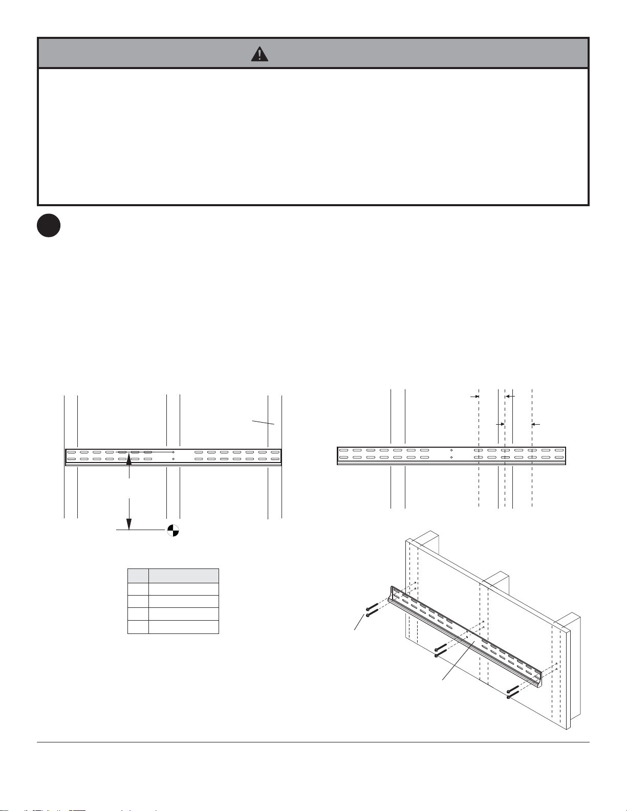
Installation to Double Wood Stud Wall
WARNING
• Installer must verify that the supporting surface will safely support the combined load of the equipment and all attached
hardware and components.
• Tighten wood screws so that wall plate is firmly attached, but do not overtighten. Overtightening can damage the
screws, greatly reducing their holding power.
• Never tighten in excess of 80 in. • lb (9 N.M.).
• Make sure that mounting screws are anchored into the center of the stud. The use of an "edge to edge" stud finder is
highly recommended.
• Hardware provided is for attachment of mount through standard thickness drywall or plaster into wood studs. Installers
are responsible to provide hardware for other types of mounting situations.
NOTE: If mounting equipment weighing greater than 100 lbs, triple stud mounting is strongly recommended.
Skip to page 5.
Wall plate (A) can be mounted to two studs that are 16" apart. Use a stud finder to locate the edges of the studs.
1
Use of an edge-to-edge stud finder is highly recommended. Based on their edges, draw a vertical line down each
stud’s center. Place wall plate on wall as a template. The top mounting slots should be located above the desired
screen center as shown in figure 1.1. Note: Screen tilt will determine wall plate location. Level plate, and mark the
center of the two mounting holes. Make sure that the mounting holes are on the stud centerlines. Drill two 5/32"
(4 mm) dia. holes 2-1/2" (65 mm) deep. Make sure that the wall plate is level, secure it using two #14 x 2.5" wood
screws (C) as shown in figure 1.2.
Skip to step 2 on page 7.
A
X
CENTER OF
SCREEN
Tilt X Distance
0° 5.8" (147 mm)
2° 2.8" (71 mm)
5° 5.8" (147 mm)
10° 2.8" (71 mm)
STUD
fig. 1.1
C
A
PFT640
WALLPLATE SHOWN
Visit the Peerless Web Site at www.peerlessmounts.com
4 of 27
fig. 1.2
ISSUED: 05-17-07 SHEET #: 202-9208-3 5-7-08
For customer care call 1-800-865-2112 or 708-865-8870.
Installation to Triple Wood Stud Wall
WARNING
• Installer must verify that the supporting surface will safely support the combined load of the equipment and all attached
hardware and components.
• Tighten wood screws so that wall plate is firmly attached, but do not overtighten. Overtightening can damage the
screws, greatly reducing their holding power.
• Never tighten in excess of 80 in. • lb (9 N.M.).
• Make sure that mounting screws are anchored into the center of the stud. The use of an "edge to edge" stud finder is
highly recommended.
• Hardware provided is for attachment of mount through standard thickness drywall or plaster into wood studs. Installers
are responsible to provide hardware for other types of mounting situations.
Wall plate (A) can be mounted to three studs that are 16" apart. Use a stud finder to locate the edges of the studs.
1
Use of an edge-to-edge stud finder is highly recommended. Based on their edges, draw a vertical line down each
stud’s center. Place wall plate on wall as a template. The top mounting slots should be located above the desired
screen center as shown in figure 1.3. Note: Screen tilt will determine wall plate location. Level plate, and mark the
center of the six mounting holes. Make sure that the mounting holes are on the stud centerlines. Drill six 5/32"
(4 mm) dia. holes 2-1/2" (65 mm) deep. Make sure that the wall plate is level, secure it using six #14 x 2.5" wood
screws (C) as shown in figure 1.4.
NOTE: When mounting equipment weighing greater than 100 lbs, triple stud mounting is strongly recommended. If
mounting to two studs, wall plate may be mounted up to 4" (102 mm) off-center as shown in figure 1.5.
Skip to step 2 on page 7.
X
fig. 1.3
Tilt X Distance
0° 9" (229 mm)
2° 6" (152 mm)
5° 9" (229 mm)
10° 6" (152 mm)
CENTER OF
SCREEN
STUD
4"
(102 mm)
fig. 1.5
C
Visit the Peerless Web Site at www.peerlessmounts.com
5 of 27
A
PFT660
WALLPLATE SHOWN
fig. 1.4
ISSUED: 05-17-07 SHEET #: 202-9208-3 5-7-08
For customer care call 1-800-865-2112 or 708-865-8870.
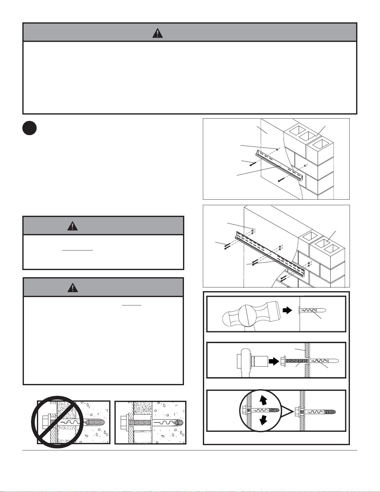
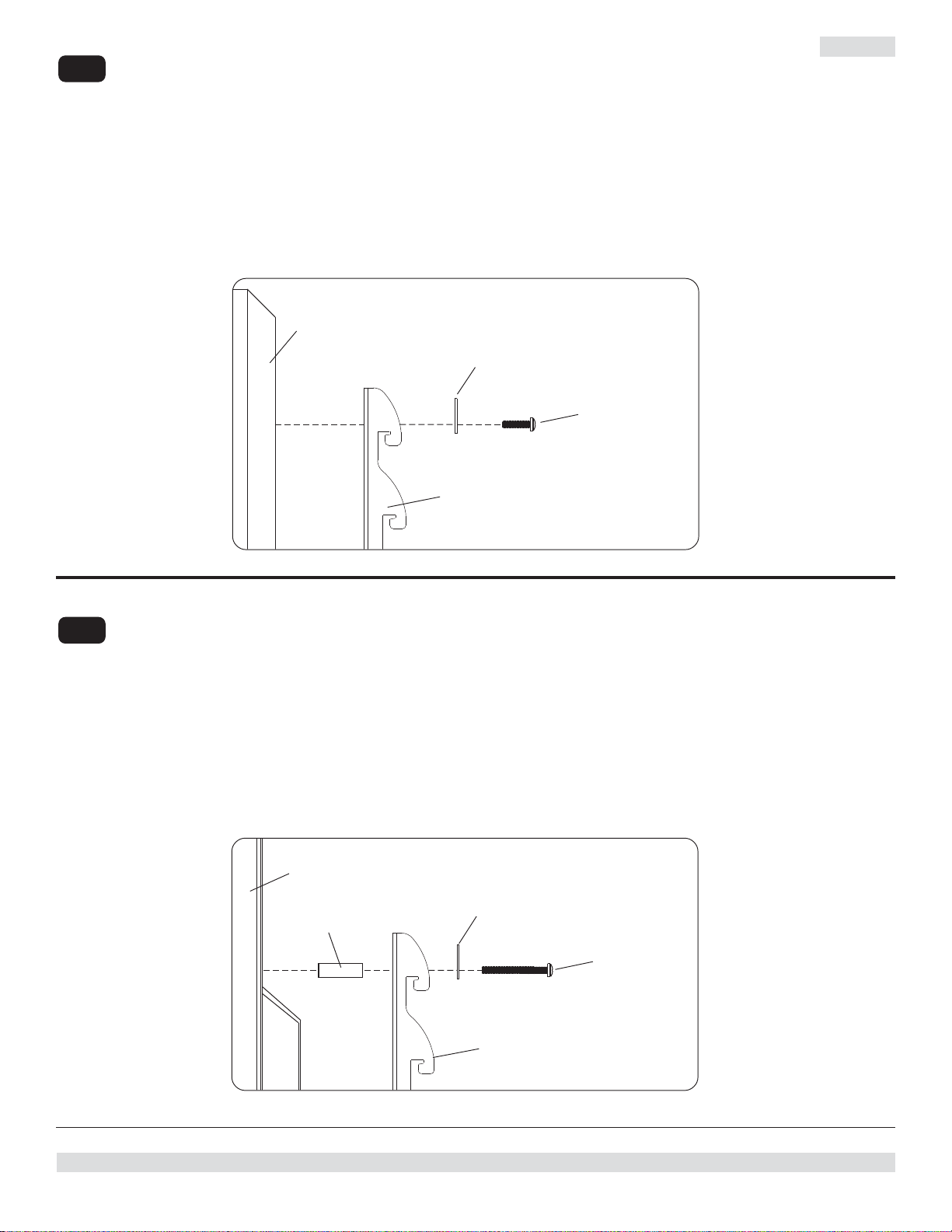
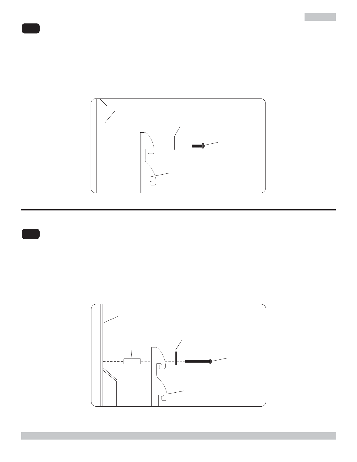
Installation to Solid Concrete or Cinder Block
WARNING
• When installing Peerless wall mounts on cinder block, verify that you have a minimum of 1-3/8" of actual concrete
thickness in the hole to be used for the concrete anchors. Do not drill into mortar joints! Be sure to mount in a solid
part of the block, generally 1" minimum from the side of the block. Cinder block must meet ASTM C-90 specifications. It is suggested that a standard electric drill on slow setting is used to drill the hole instead of a hammer drill to
avoid breaking out the back of the hole when entering a void or cavity.
• Concrete must be 2000 psi density minimum. Lighter density concrete may not hold concrete anchor.
• Make sure that the supporting surface will safely support the combined load of the equipment and all attached hardware and components.
Make sure that wall plate (A) is level, use it as a
1
template to mark two mounting holes. The top
mounting hole should be above the desired screen
center as shown in figure 1.1 on page 4 or figure 1.3 on
page 5. NOTE: Screen tilt will determine wall plate
location. Drill two 1/4" (6 mm) dia. holes to a minimum
depth of 2.5" (64 mm). Insert anchors (D) in holes flush
with wall as shown (right). Place wall plate over
anchors and secure with #14 x 2.5" screws (C). Level,
then tighten all fasteners.
NOTE: Six holes and six sets of fasteners are required
when mounting the PFT660 wall plate.
WARNING
• Tighten screws so that wall plate is firmly attached,
but do not overtighten. Overtightening can damage
screws, greatly reducing their holding power.
• Never tighten in excess of 80 in. • lb (9 N.M.).
WARNING
• Always attach concrete anchors directly to loadbearing concrete.
• Never attach concrete anchors to concrete covered
with plaster, drywall, or other finishing material. If
mounting to concrete surfaces covered with a finishing
surface is unavoidable, the finishing surface must be
counterbored as shown below. Be sure concrete
anchors do not pull away from concrete when tightening screws. If plaster/drywall is thicker than 5/8",
custom fasteners must be supplied by installer (not
UL approved).
solid concrete
cinder block
D
C
A
PFT640
WALLPLATE
solid concrete
D
cinder block
C
A
PFT660
WALLPLATE
1
concrete surface
D
Drill holes and insert anchors (D).
2
Place plate (A) over anchors (D) and secure with screws (C).
A
C
D
INCORRECT CORRECT
wall
plate
plaster/
CUTAWAY VIEW
Visit the Peerless Web Site at www.peerlessmounts.com
dry wall
concrete
wall
plate
plaster/
dry wall
concrete
6 of 27
3
Tighten all fasteners.
ISSUED: 05-17-07 SHEET #: 202-9208-3 5-7-08
For customer care call 1-800-865-2112 or 708-865-8870.
Installing Vertical Brackets
WARNING
• Tighten screws so adapter brackets are firmly attached. Do not tighten with excessive force. Overtightening can cause
stress damage to screws, greatly reducing their holding power and possibly causing screw heads to become
detached. Tighten to 40 in. • lb (4.5 N.M.) maximum torque.
• If screws don't get three complete turns in the screen inserts or if screws bottom out and bracket is still not tightly
secured, damage may occur to screen or product may fail.
To prevent scratching the screen, set a cloth on a flat, level surface that will support the weight of the screen. Place
2
screen face side down. If screen has knobs on the back, remove them to allow the adapter brackets to be attached.
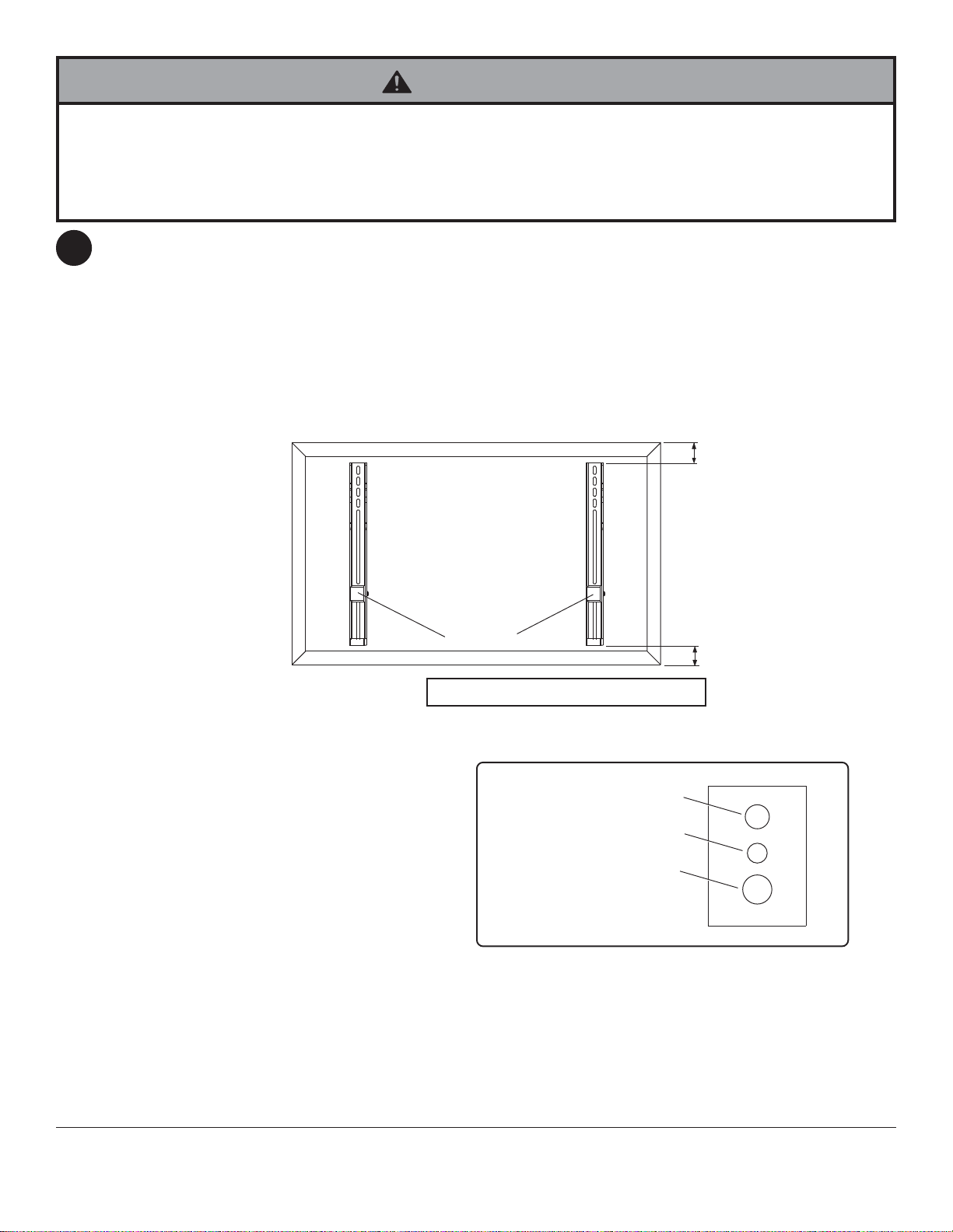
Place vertical brackets (B) on back of screen. Align to holes, and center on back of screen as shown in figure 2.1.
Attach the vertical brackets to the back of the screen using the appropriate combination of screws, multi-washers, and
spacers as shown in figure 2.3. NOTE: Be sure to attach vertical brackets with wall support brackets positioned at the
bottom of screen as shown in figure 2.1.
NOTE: Top and bottom mounting holes must be used for attaching brackets. Middle holes should also be used where
the fasteners and screens allow.
Verify that all holes are properly aligned, and then tighten screws using a phillips screwdriver.
fig. 2.1
Notes:
• Always use multi-washers when attaching
vertical brackets (B) to your screen.
• Use the corresponding hole in the multiwasher that matches your screw size as
shown in figure 2.2.
• Spacers may not be used, depending upon
the type of screen.
CENTER BRACKETS
X
VERTICALLY ON BACK OF
SCREEN
WALL
SUPPORT
BRACKETS
X
NOTE: "X" dimensions should be equal.
MULTI-WASHER
MEDIUM HOLE FOR M5 SCREWS
SMALL HOLE FOR M4 SCREWS
LARGE HOLE FOR M6 SCREWS
fig. 2.2
NOTE: For flat back screens proceed to step 2-3. For bump-out or recessed back screen skip to step 2-4
ISSUED: 05-17-07 SHEET #: 202-9208-3 5-7-08
Visit the Peerless Web Site at www.peerlessmounts.com
7 of 27
For customer care call 1-800-865-2112 or 708-865-8870.

For Flat Back Screen
If you have any questions, please call Peerless customer care at 1-800-865-2112 or visit our website at
2- 3
www.peerlessmounts.com/1 for PFT640 models or www.peerlessmounts.com/6 for PFT660 models, to locate
your screen compatibility chart.
Begin with the shortest length screw, hand thread through multi-washer and adapter bracket into screen as shown
below. Screw must make at least three full turns into the mounting hole and fit snug into place. Do not over tighten.
If screw cannot make three full turns into the screen, select a longer length screw from the baffled fastener pack.
Repeat for remaining mounting holes, level brackets and tighten screws.
NOTE: Spacers may not be used, depending upon the type of screen.
fig. 2.3
SCREEN
MULTI-WASHER
SCREW
ADAPTER BRACKET (B)
If you have any questions, please call Peerless customer care at 1-800-865-2112.
For Bump-out or Recessed Back Screen
If you have any questions, please call Peerless customer care at 1-800-865-2112 or visit our website at
2- 4
www.peerlessmounts.com/1 for PFT640 models or www.peerlessmounts.com/6 for PFT660 models, to locate
your screen compatibility chart.
Begin with longer length screw, hand thread through multi-washer, adapter bracket and spacer in that order into
screen as shown below. Screw must make at least three full turns into the mounting hole and fit snug into place.
Do not over tighten. If screw cannot make three full turns into the screen, select a longer length screw from the
baffled fastener pack. Repeat for remaining mounting holes, level brackets and tighten screws.
SCREEN
SPACER
fig. 2.4
MULTI-WASHER
SCREW
If you have any questions, please call Peerless customer care at 1-800-865-2112.
Visit the Peerless Web Site at www.peerlessmounts.com
ADAPTER BRACKET (B)
8 of 27
ISSUED: 05-17-07 SHEET #: 202-9208-3 5-7-08
For customer care call 1-800-865-2112 or 708-865-8870.
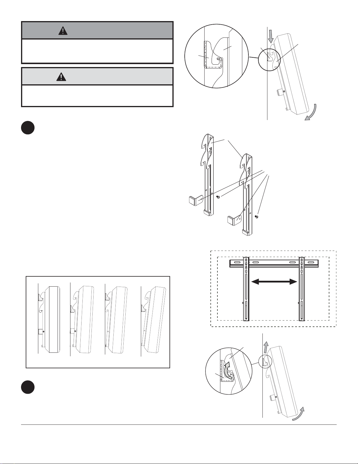
WARNING
• Always use an assistant or mechanical lifting equipment to safely lift and position the plasma television.
CAUTION
• Be careful not to pinch fingers when pushing screen
from the bottom.
Mounting Flat Panel Screen
To Mount Screen With No Tilt or 2° Tilt
3
Hook vertical brackets (B) onto wall plate (A)
using top hooks for no tilt and bottom hooks for 2°
tilt as shown in figure 3.3. Hooks of vertical
brackets must be engaged securely onto wall
plate as shown in detail 1, then slowly swing
screen toward wall as shown in figure 3.1.
Screen can be adjusted horizontally if desired as
shown in figure 3.4.
To Mount Screen With 5° or 10° Tilt
Remove wall support brackets and screws from
vertical brackets as shown in figure 3.2. Hook
vertical brackets (B) onto wall plate (A) using top
hooks for 5° tilt and bottom hooks for 10° tilt as
shown in figure 3.3. Hooks of vertical brackets
must be engaged securely onto wall plate as
shown in detail 1, then slowly swing screen
toward wall as shown in figure 3.1.
Screen can be adjusted horizontally if desired as
shown in figure 3.4.
A
DETAIL 1
fig. 3.2
B
B
fig. 3.1
BA
REMOVE
WALL SUPPORT
BRACKETS AND SCREWS
FOR 5° OR 10° TILT
FLAT
2° TILT
5° TILT
fig. 3.3
Removing Flat Panel Screen
To remove screen from mount, slowly swing
4
bottom of screen away from wall and slightly
push top of screen toward wall to disengage
hooks on vertical brackets (B) from wall plate (A).
Lift screen off of wall plate as shown in figure 4.1.
Visit the Peerless Web Site at www.peerlessmounts.com
10° TILT
fig. 3.4
B
A
fig. 4.1
9 of 27
For customer care call 1-800-865-2112 or 708-865-8870.
All other brand and product names are trademarks or registered trademarks of their respective owners.
ISSUED: 05-17-07 SHEET #: 202-9208-3 5-7-08
© 2008, Peerless Industries, Inc. All rights reserved.

Español
Instalación y ensamblaje:
Soporte de pared ParamountTM plano y con capacidad de
inclinación para televisores de pantalla plana de LCD o de plasm
Este producto está clasificado por Underwriters Laboratories (UL) para
utilizarse con pantallas dentro de las gamas de tamaños y de la
capacidad de soportar carga ____ según lo indicado en la tabla que
R
Este producto debe ser utilizado con productos
que lleven la marca UL (Underwrites Laboratory)
y tiene que ser instalado por un instalador
profesional calificado.
aparece continuación.
Nº de modelo Gama de tamaños de la pantalla Capacidad máxima de soportar carga según UL:
PFT640 23" - 46" 100 lb (45 kg)
PFT660 37" - 60" 175 lb (79 kg)
Características:
• Función integrada para instalación con o sin
inclinación de la pantalla
• Inclinación ajustable a 0°, 2°, 5° y 10°
10 de 27
3215 W. North Ave. • Melrose Park, IL 60160 • (800) 865-2112 ó (708) 865-8870 • Fax: (708) 865-2941 • www.peerlessmounts.com
Visite el sitio Web de Peerless en www.peerlessmounts.com Para el Servicio al cliente llame al 1-800-729-0307 ó 708-865-8870
PUBLICADO: 05-17-07 HOJA #: 202-9208-3 05-07-08

Nota: Lea la hoja de instrucciones completa antes de comenzar la instalación y el ensamblaje.
ADVERTENCIA
• No comience a instalar su producto de Peerless hasta haber leído y entendido las instrucciones y las advertencias
contenidas en la Hoja de Instalación. Si tiene alguna pregunta acerca de cualquiera de las instrucciones o las
advertencias, por favor, llame a Servicio al Cliente de Peerless al 1-800-865-2112.
• Este producto sólo debe ser instalado por una persona que tenga una aptitud mecánica, que tenga experiencia en
construcción básica de edificios y que entienda estas instrucciones en su totalidad.
• Asegúrese de que la superficie de apoyo sostendrá, con seguridad, la carga combinada del equipo y todos los
fijadores y componentes.
• Nunca sobrepase la capacidad máxima de soportar carga aceptada por Underwriters Laboratories. (Vea la página 9).
• Si va a instalar el producto en una pared con montantes de madera, asegúrese de que los tornillos de montaje estén
anclados en el centro de los montantes. Se recomienda utilizar un localizador de montantes de “borde a borde”.
• Siempre cuente con la ayuda de un asistente o utilice un equipo mecánico de izar para levantar y colocar el equipo
con más seguridad.
• Apriete los tornillos con firmeza, pero no en exceso. Apretarlos en exceso puede dañar los artículos y puede
disminuir significativamente su fuerza de fijación.
• Este producto está diseñado para uso en interiores solamente. Utilizar este producto en exteriores podría causar
fallas del producto y lesiones a individuos.
• Este producto fue diseñado con la intención de que se instale en las superficies de apoyo marcadas abajo con los
accesorios de instalación incluidos en este producto como se especifica en la hoja de instalación. Para instalar este
producto en otra superficie de apoyo, llame a Servicio al Cliente de Peerless al 1-800-865-2112.
• Este producto fue diseñado para ser instalado en paredes con la siguiente construcción solamente:
CONSTRUCCIÓN DE LA PARED ACCESORIOS ADICIONALES NECESARIOS
x Montante de madera Ninguno
x Viga de madera Ninguno
x Concreto macizo Ninguno
x Bloque de hormigón de escorias Ninguno
Montante de metal No lo instale excepto con el juego de accesorios de Peerless para
montantes de metal.
Llame a Servicio al Cliente para pedir el juego de accesorios de
Peerless para montantes de metal.
Ladrillo Comuníquese con Servicio al Cliente.
¿Otra superficie o no está seguro? Comuníquese con Servicio al Cliente.
Español
Herramientas necesarias para el ensamblaje
• localizador de montantes (se recomienda uno de “borde a borde”)
• destornillador phillips
• taladro
• broca de 1/4" para paredes de concreto y de bloque de hormigón de
escorias
• broca de 1/2" para paredes con montantes de metal
• broca de 5/32" para paredes con montantes de metal o de madera
• nivel
Accesorios
• Juego de accesorios de 4 piezas para la
fijación en montantes de metal (ACC 415)
(El montante de metal no ha sido evaluado
por UL)
• Juego de accesorios de 2 piezas para la
fijación en montantes de metal (ACC 215)
(El montante de metal no ha sido evaluado
por UL)
Tabla de contenido
Lista de piezas ............................................................................................................................................................. 12
Instalación en una pared con montantes de madera dobles ......................................................................................... 13
Instalación en una pared con montantes de madera triples .......................................................................................... 14
Instalación en una pared de concreto macizo o de bloques de hormigón de escorias .................................................. 15
Instalación de los soportes verticales ........................................................................................................................... 16
Instalación de la pantalla plana en la placa de pared .................................................................................................... 18
Para recibir servicio al cliente, llame al (800) 865-2112 o al (708) 865-8870.
11 de 27
Visite el sitio Web de Peerless en www.peerlessmounts.com Para el Servicio al cliente llame al 1-800-729-0307 ó 708-865-8870
PUBLICADO: 05-17-07 HOJA #: 202-9208-3 05-07-08

Antes de comenzar, asegúrese de que su producto contiene todas las piezas que se muestran.
PFT640 PFT660
Descripción Cantidad
N.o de pieza N.o de pieza
A placa de pared 1 201-P1300 201-P1311
B soporte vertical 2 201-0370 201-0371
C tornillo para madera de 14 x 2.5" 4 5S1-015-C03
6 5S1-015-C03
D anclaje alligator® 4 590-0097
6 590-0097
Lista de piezas
Las piezas pueden verse un poco distintas a la ilustración.
A
PLACA DE
PARED PTF640
A
PLACA DE
PARED PTF660
B
C
Español
D
Fijaciones para los soportes adaptadores
Nota: El juego de fijaciones Sorted-for-YouTM incluido con este producto fue hecho para su producto específicamente y es posible
que no contenga todos los componentes que se muestran abajo.
M4 x 12 mm
504-9013
M4 x 25 mm
504-1015
M8 x 16 mm
520-9257
M8 x 25 mm
520-1031
Visite el sitio Web de Peerless en www.peerlessmounts.com Para el Servicio al cliente llame al 1-800-729-0307 ó 708-865-8870
M5 x 12 mm
520-1027
M5 x 25 mm
520-9543
M8 x 40 mm
520-1136
M6 x 12 mm
520-1128
I.D. 5.6 mm
540-1057
I.D. 5.1 mm
540-1040
12 de 27
M6 x 20 mm
520-9402
I.D. 6.5 mm
540-1058
I.D. 8.7 mm
540-1059
PUBLICADO: 05-17-07 HOJA #: 202-9208-3 05-07-08
M6 x 25 mm
520-1208
M6 x 30 mm
510-9109
arandela múltiple
580-1036

Instalación en una pared con montantes de madera dobles
Español
ADVERTENCIA
• El instalador tiene que asegurarse de que la superficie de apoyo sostendrá, con seguridad, la carga combinada del
equipo y todos los fijadores y componentes.
• Apriete los tornillos de madera de manera que la placa de pared se fije firmemente, pero no en exceso. Apretarlos en
exceso puede dañar los tornillos y puede disminuir significativamente su fuerza de fijación.
• Nunca apriete a más de 80 pulg-lb (9 N•m).
• Asegúrese de que los tornillos de montaje estén anclados en el centro del montante. Se recomienda utilizar un
localizador de montantes de “borde a borde”.
• Los accesorios para la instalación que se proveen son para fijar el soporte a montantes de madera a través de tabique
de yeso-cartón o yeso de espesor estándar. Los instaladores son responsables de suministrar los accesorios
necesarios para otros tipos de instalaciones.
Nota: Si va a instalar un equipo que pese más de 100 lbs, se recomienda encarecidamente que lo instale en tres
(3) montantes.
Pase a la página 14.
La placa de pared (A) se puede instalar en dos montantes que tengan una separación de 16". Utilice un
1
localizador de montantes para localizar los bordes de los montantes. Se recomienda utilizar un localizador de
montantes de “borde a borde”. Tomando los bordes como punto de referencia, trace una línea vertical por el
centro de cada montante. Coloque la placa de pared contra la pared para utilizarla como plantilla. Las ranuras
superiores de montaje deben estar ubicadas encima del punto donde quiere que quede el centro de la pantalla,
como se muestra en la figura 1.1. Nota: La ubicación de la placa de pared dependerá de la inclinación de la
pantalla. Nivele la placa y marque el centro de los dos agujeros de montaje. Asegúrese de que los agujeros de
montaje estén sobre las líneas que trazó por el centro de los montantes. Taladre dos agujeros de 5/32" (4 mm)
de diámetro y 2-1/2" (65 mm) de profundidad. Asegúrese de que la placa esté nivelada, fíjela utilizando dos
tornillos para madera de 14 x 2.5" (C), como se muestra en la ilustración 1.2.
Proceda al paso 2 en la página 16.
MONTANTE
A
X
CENTRO DE
LA PANTALLA
Inclinación Distancia X
0° 5.8" (147 mm)
2° 2.8" (71 mm)
5° 5.8" (147 mm)
10° 2.8" (71 mm)
fig. 1.1
C
A
PFT640
PLACA DE PARED QUE
SE MUESTRA
fig. 1.2
13 de 27
Visite el sitio Web de Peerless en www.peerlessmounts.com Para el Servicio al cliente llame al 1-800-729-0307 ó 708-865-8870
PUBLICADO: 05-17-07 HOJA #: 202-9208-3 05-07-08

Instalación en una pared con montantes de madera triples
Español
ADVERTENCIA
• El instalador tiene que asegurarse de que la superficie de apoyo sostendrá, con seguridad, la carga combinada del
equipo y todos los fijadores y componentes.
• Apriete los tornillos de madera de manera que la placa de pared se fije firmemente, pero no en exceso. Apretarlos en
exceso puede dañar los tornillos y puede disminuir significativamente su fuerza de fijación.
• Nunca apriete a más de 80 pulg-lb (9 N•m).
• Asegúrese de que los tornillos de montaje estén anclados en el centro del montante. Se recomienda utilizar un
localizador de montantes de “borde a borde”.
• Los accesorios para la instalación que se proveen son para fijar el soporte a montantes de madera a través de tabique
de yeso-cartón o yeso de espesor estándar. Los instaladores son responsables de suministrar los accesorios
necesarios para otros tipos de instalaciones.
La placa de pared (A) se puede instalar en tres montantes que tengan una separación de 16". Utilice un localizador
1
de montantes para localizar los bordes de los montantes. Se recomienda utilizar un localizador de montantes de
“borde a borde”. Tomando los bordes como punto de referencia, trace una línea vertical por el centro de cada
montante. Coloque la placa de pared contra la pared para utilizarla como plantilla. Las ranuras superiores de
montaje deben estar ubicadas encima del punto donde quiere que quede el centro de la pantalla, como se muestra
en la figura 1.3. Nota: La ubicación de la placa de pared dependerá de la inclinación de la pantalla. Nivele la placa y
marque el centro de los seis agujeros de montaje. Asegúrese de que los agujeros de montaje estén sobre las líneas
que trazó por el centro de los montantes. Taladre seis agujeros de 5/32" (4 mm) de diámetro y 2-1/2" (65 mm) de
profundidad. Asegúrese de que la placa esté nivelada, fíjela utilizando seis tornillos para madera de 14 x 2.5" (C),
como se muestra en la ilustración 1.4.
Nota: Al instalar un equipo que pese más de 100 lbs, se recomienda encarecidamente que lo instale en tres (3)
montantes. Si la instalación se va a hacer en dos (2) montantes, la placa de pared se puede instalar a una distancia
de hasta 4" (102 mm) del centro, como se muestra en la figura 1.5.
Proceda al paso 2 en la página 16.
4"
fig. 1.5
MONTANTE
(102 mm)
X
fig. 1.3
CENTRO DE
LA PANTALLA
Inclinación Distancia X
0° 9" (229 mm)
2° 6" (152 mm)
5° 9" (229 mm)
10° 6" (152 mm)
C
PFT660
PLACA DE PARED QUE
SE MUESTRA
A
fig. 1.4
14 de 27
Visite el sitio Web de Peerless en www.peerlessmounts.com Para el Servicio al cliente llame al 1-800-729-0307 ó 708-865-8870
PUBLICADO: 05-17-07 HOJA #: 202-9208-3 05-07-08

Español
Instalación en una pared de concreto macizo o de bloques de hormigón de escorias
ADVERTENCIA
• Cuando vaya a instalar soportes de pared de Peerless en bloques de hormigón de escorias, asegúrese de que cuente
con una capa de concreto de un grosor mínimo de 1-3/8" en el agujero, que pueda usar para los anclajes para concreto. ¡No taladre en juntas de argamasa! Asegúrese de hacer la instalación en la parte sólida del bloque, por lo
general, a un mínimo de 1" del extremo del bloque. Los bloques de hormigón de escorias tienen que cumplir las
especificaciones de la ASTM C-90. Se sugiere utilizar un taladro eléctrico convencional a baja velocidad para hacer el
agujero en vez de un taladro percutor para no perforar el fondo del agujero al entrar en un vacío o una cavidad.
• El concreto tiene que tener una densidad mínima de 2,000 psi. Es posible que un concreto de menos densidad no
sostenga el anclaje para concreto.
• Asegúrese de que la superficie de apoyo sostendrá, con seguridad, la carga combinada del equipo y todos los
fijadores y componentes.
Asegúrese de que la placa de pared (A) esté nivelada y
utilícela como plantilla para marcar dos agujeros de montaje.
1
El agujero de montaje superior debe quedar encima del
punto donde quiere que quede el centro de la pantalla, como
se muestra en la figura 1.1 de la página 12 o en la figura 1.3
de la página 13. Nota: La ubicación de la placa de pared
dependerá de la inclinación de la pantalla. Taladre dos
agujeros de 1/4" (6 mm) de diámetro a una profundidad
mínima de 2.5" (64 mm). Inserte los anclajes (D) en los
agujeros a ras con la pared, como se muestra (a la derecha).
Coloque la placa de pared sobre los anclajes y fíjela con los
tornillos de 14 x 2.5" (C). Nivele y apriete todas las fijaciones.
NOTA: Se necesitan seis agujeros y seis juegos de fijaciones
para instalar la placa de pared PFT660.
ADVERTENCIA
• Apriete los tornillos de manera que la placa de pared
se fije firmemente, pero no en exceso. Apretarlos en
exceso puede dañar los tornillos y puede disminuir
significativamente su fuerza de fijación.
• Nunca apriete a más de 80 pulg-lb (9 N•m).
ADVERTENCIA
• Siempre fije los anclajes para concreto directamente
en la pared que sostiene la carga.
• Nunca fije los anclajes para concreto a una pared de
concreto recubierta con yeso, tabique de yeso-cartón
u otro material de acabado. Si es inevitable hacer la
instalación en una superficie de concreto recubierta
con una superficie de acabado, la superficie de
acabado tiene que ser escariada, como se muestra
abajo. Asegúrese de que los anclajes para concreto
no se separen del concreto cuando apriete los
tornillos. Si el grosor de la capa de yeso o tabique de
yeso-cartón tiene un grosor mayor de 5/8", el
instalador tiene que suministrar las fijaciones
especiales (no aprobado por UL).
INCORRECTO
placa de
pared
concreto
placa de
pared
CORRECTO
concreto
concreto macizo
bloque de
hormigón de
escorias
D
C
A
PFT640
PLACA DE PARED
concreto macizo
D
bloque de
hormigón de
escorias
C
A
PFT660
PLACA DE PARED
1
TECHO DE
CONCRETO
D
Taladre los agujeros e inserte los anclajes (D).
2
A
C
Coloque la placa (A) sobre los anclajes (D) y fíjela con los
tornillos (C).
3
D
VISTA EN CORTE
Visite el sitio Web de Peerless en www.peerlessmounts.com Para el Servicio al cliente llame al 1-800-729-0307 ó 708-865-8870
yeso / tabique de yeso-cartón
yeso / tabique de yeso-cartón
15 de 27
Apriete todas las fijaciones.
PUBLICADO: 05-17-07 HOJA #: 202-9208-3 05-07-08

Instalación de los soportes verticales
Español
ADVERTENCIA
• Apriete los tornillos de manera que los soportes adaptadores se fijen con firmeza. No los apriete con fuerza excesiva.
Apretar los tornillos en exceso puede causarles daño por forzarlos y puede disminuir significativamente su fuerza de
fijación y podría causar el desprendimiento de las cabezas de los tornillos. Apriete los tornillos a un máximo de 40
pulg-lb (4.5 N•m) de par torsor.
• Si no se les da tres vueltas completas a los tornillos en los insertos de la pantalla o si los tornillos topan fondo y el
soporte todavía no está firme, se podría dañar la pantalla o el producto podría no funcionar bien.
Para no rayar la pantalla, coloque un trapo sobre una superficie plana y nivelada que sostenga el peso de la pantalla.
2
Coloque la pantalla boca abajo. Si la pantalla tiene perillas en la parte trasera, quíteselas para poder fijar los soportes
adaptadores. Coloque los soportes verticales (B) en la parte trasera de la pantalla. Centralícelos con los agujeros en la
parte trasera de la pantalla, como se muestra en la figura 2.1. Fije los soportes verticales en la parte trasera de la pantalla
utilizando la combinación adecuada de tornillos, arandelas múltiples y espaciadores, como se muestra en la figura 2.3.
Nota: Asegúrese de fijar los soportes verticales con los soportes sostenedores de pared ubicados en la parte inferior de la
pantalla, como se muestra en la figura 2.1.
Nota: Siempre se tienen que usar los agujeros superiores y los inferiores para la instalación. También se deben usar los
agujeros centrales en los casos en los que las fijaciones y las pantallas lo permitan.
Verifique que todos los agujeros estén debidamente alineados y luego apriete los tornillos usando un destornillador
phillips.
fig. 2.1
Nota: Las dimensiones “X” deben ser iguales.
Notas:
• Siempre utilice arandelas múltiples al fijar los
soportes verticales (B) a la pantalla.
• Utilice el agujero correspondiente de la arandela
múltiple que sea del mismo tamaño del tornillo,
como se muestra en la figura 2.2.
• Es posible que no necesite usar los
espaciadores, dependiendo del tipo de pantalla.
CENTRALICE LOS
X
SOPORTES
VERTICALMENTE EN LA
PARTE TRASERA DE LA
PANTALLA
SOPORTES
SOSTENEDORES DE
PARED
X
ARANDELA MÚLTIPLE
AGUJERO MEDIANO PARA
TORNILLOS M5
AGUJERO PEQUEÑO
PARA TORNILLOS M4
AGUJERO GRANDE PARA
TORNILLOS M6
fig. 2.2
NOTA: En el caso de los televisores que tienen la parte posterior plana, pase al paso 2-3. En el caso de los
televisores que tienen la parte posterior abultada o empotrada, pase al paso 2-4.
16 de 27
Visite el sitio Web de Peerless en www.peerlessmounts.com Para el Servicio al cliente llame al 1-800-729-0307 ó 708-865-8870
PUBLICADO: 05-17-07 HOJA #: 202-9208-3 05-07-08
Instalación de un televisor que tiene la parte posterior plana
Refiérase a la Tabla de compatibilidad de las pantallas para determinar cuáles son los sujetadores adecuados
2- 3
para usarse. Acceda a www.peerlessmounts.com/1 si se trata de los modelos PFT640 o
www.peerlessmounts.com/6 si se trata de los modelos PFT660 para ver una tabla completa de las pantallas
compatibles con este soporte.
Comience con uno de los tornillos más cortos, enrósquelo, con la mano, a través de la arandela múltiple y el soporte
adaptador a la parte posterior de la pantalla, como se muestra abajo. El tornillo debe dar, por lo menos, tres vueltas
completas dentro del agujero de instalación y debe quedar ajustado en su lugar. No apriete los tornillos en exceso. Si el
tornillo no puede dar tres vueltas completas al entrar en la parte posterior de la pantalla, seleccione un tornillo más largo
de los sujetadores identificados y clasificados en las divisiones del empaque plástico. Siga el mismo procedimiento con
los agujeros de instalación restantes, nivele los soportes y apriete los tornillos.
NOTA: Es posible que no necesite usar los espaciadores, dependiendo del tipo de pantalla.
PANTALLA
ARANDELA
MÚLTIPLE
Español
fig. 2.3
TORNILLO
SOPORTE
ADAPTADOR (B)
Si tiene alguna pregunta, por favor, llame a Servicio al Cliente de Peerless al 1-800-865-2112.
Instalación de un televisor que tiene la parte posterior abultada o empotrada
Refiérase a la Tabla de compatibilidad de las pantallas para determinar cuáles son los sujetadores adecuados
2- 4
para usarse. Acceda a www.peerlessmounts.com/1 si se trata de los modelos PFT640 o
www.peerlessmounts.com/6 si se trata de los modelos PFT660 para ver una tabla completa de las pantallas
compatibles con este soporte.
Comience con uno de los tornillos más largos, enrósquelo, con la mano, a través de la arandela múltiple, el soporte
adaptador y el espaciador, en ese orden, a la parte posterior de la pantalla, como se muestra abajo. El tornillo debe
dar, por lo menos, tres vueltas completas dentro del agujero de instalación y debe quedar ajustado en su lugar. No
apriete los tornillos en exceso. Si el tornillo no puede dar tres vueltas completas al entrar en la parte posterior de la
pantalla, seleccione un tornillo más largo de los sujetadores identificados y clasificados en las divisiones del
empaque plástico. Siga el mismo procedimiento con los agujeros de instalación restantes, nivele los soportes y
apriete los tornillos.
PANTALLA
ESPACIADOR
ARANDELA
MÚLTIPLE
fig. 2.4
TORNILLO
SOPORTE
ADAPTADOR (B)
Si tiene alguna pregunta, por favor, llame a Servicio al Cliente de Peerless al 1-800-865-2112.
17 de 27
Visite el sitio Web de Peerless en www.peerlessmounts.com Para el Servicio al cliente llame al 1-800-729-0307 ó 708-865-8870
PUBLICADO: 05-17-07 HOJA #: 202-9208-3 05-07-08

ADVERTENCIA
Español
• Siempre cuente con un asistente o con un equipo
mecánico de izar para levantar y colocar el televisor
de plasma con más seguridad.
PRECAUCIÓN
• Tenga cuidado de no pincharse los dedos cuando
empuje la pantalla por la parte inferior.
Instalación de la pantalla plana
Para instalar la pantalla sin inclinación o con 2° de
3
inclinación
Enganche los soportes verticales (B) en la placa de pared (A) utilizando los
ganchos superiores para que la pantalla no tenga inclinación o los ganchos
inferiores para que tenga una inclinación de 2°, como se muestra en la figura
3.3. Los ganchos de los soportes verticales tienen que encajar con firmeza en
la placa de pared, como se muestra en el detalle 1; entonces empuje la
pantalla lentamente hacia la pared, como se muestra en la figura 3.1.
La pantalla se puede ajustar horizontalmente si lo desea, como se muestra
en la figura 3.4.
Para instalar la pantalla con 5° o 10° de inclinación
Quite los soportes sostenedores de pared y los tornillos de los soportes
verticales, como se muestra en la figura 3.2. Enganche los soportes verticales
(B) en la placa de pared (A) utilizando los ganchos superiores para que la
pantalla tenga una inclinación de 5° o los ganchos inferiores para que tenga
una inclinación de 10°, como se muestra en la figura 3.3. Los ganchos de los
soportes verticales tienen que encajar con firmeza en la placa de pared, como
se muestra en el detalle 1; entonces empuje la pantalla lentamente hacia la
pared, como se muestra en la figura 3.1.
La pantalla se puede ajustar horizontalmente si lo desea, como se muestra
en la figura 3.4.
A
DETALLE 1
B
fig. 3.1
fig. 3.2
B
BA
QUITE LOS
SOPORTES
SOSTENEDORES DE
PARED Y LOS
TORNILLOS PARA
QUE LA PANTALLA
TENGA UNA
INCLINACIÓN DE 5°
O 10°
PLANO
INCLINACIÓN
DE 2°
INCLINACIÓN
DE 5°
INCLINACIÓN
DE 10°
fig. 3.4
B
fig. 3.3
Desinstalación de la pantalla plana
Para quitar la pantalla del soporte, hale la pantalla lentamente por la parte inferior
4
para separarla de la pared y empuje suavemente la parte superior de la pantalla
hacia la pared para que los ganchos de los soportes verticales (B) se salgan de la
placa de pared (A). Levante la pantalla para quitarla de la placa de pared, como se
muestra en la figura 4.1.
18 de 27
Visite el sitio Web de Peerless en www.peerlessmounts.com Para el Servicio al cliente llame al 1-800-729-0307 ó 708-865-8870
Cualesquiera otras marcas y nombres de productos son marcas comerciales o registradas de sus respectivos dueños.
A
fig. 4.1
PUBLICADO: 05-17-07 HOJA #: 202-9208-3 05-07-08
© 2008, Peerless Industries, Inc. Todos los derechos reservados.

Installation et assemblage :
Français
Monture mur ale plate et inclinable Paramount
pour écrans LCD et Plasma plats
Ce produit est évalué par l’Underwriter’s Laboratory (UL) pour la
plage de dimensions d’écrans et la capacité de charge
R
de______indiquées dans le tableau ci-dessous
Modèle nº Plage de dimensions d’écrans Capacité de charge maximale établie par l’UL :
PFT640 57,5 cm (23 po) à 115 cm (46 po) 45 kg (100 lb)
PFT660 93,9 cm (37 po) à 150 cm (60 po) 79 kg (176 lb)
Caractéristiques :
• Dispositif d’inclinaison intégré plat et fixe
• Inclinaison incrémentielle de 0º, 5º et 10º
Cet appareil est conçu pour une utilisation
avec des produits homologués UL et doit
être installé par un installateur professionnel
qualifié.
TM
19 sur 27
3215 W. North Ave. • Melrose Park, IL 60160 • 800-865-2112 ou 708-865-8870 • Télécopie : 708-865-2941 • www.peerlessmounts.com
Adresse de notre site internet : www.peerlessmounts.com
PUBLIÉ LE : 05-17-07 FEUILLE no : 202-9208-3 05-07-08
Service clientèle : 1-800-729-0307 ou 708-865-8870

Remarque : lisez entièrement la fiche d’instructions avant de commencer l’installation et l’assemblage.
Français
AVERTISSEMENT
• Ne commencez pas à installer votre produit Peerless avant d’avoir lu et assimilé les instructions et les mises en garde
contenues dans cette fiche d’installation. Pour toute question concernant les instructions ou les mises en garde,
appelez le service à la clientèle de Peerless au 1-800-865-2112.
• Ce produit ne doit être installé que par une personne ayant de bonnes aptitudes en mécanique, expérimentée en
travaux de construction élémentaires, et démontrant une parfaite compréhension de ces instructions.
• Assurez-vous que la surface de support pourra soutenir sans danger la charge combinée de l’équipement, de toute sa
visserie et de tous ses composants.
• Ne dépassez jamais la capacité de charge maximum établie par l’UL. Reportez-vous à la page 17.
• Si vous effectuez le montage sur un mur à montants en bois, assurez-vous que les vis de montage sont ancrées au
centre des montants. L’usage d’un localisateur « bord à bord » est fortement conseillé.
• Pour lever et positionner l’équipement en toute sécurité, faites-vous toujours aider par une autre personne ou utilisez
un matériel de levage mécanique.
• Serrez fermement les vis, mais sans excès. Un serrage excessif peut endommager les éléments et en réduire
considérablement le pouvoir de maintien.
• Ce produit est conçu uniquement pour un usage intérieur. L’utilisation de ce produit à l’extérieur peut causer une
défaillance du produit et des blessures corporelles.
• Ce produit a été conçu et prévu pour être monté sur les surface de support mentionnées ci-après ; la visserie incluse
dans ce produit est celle spécifiée sur la fiche d’installation. Pour monter ce produit sur une autre surface de support,
adressez-vous au service clientèle de Peerless au 1-800-865-2112.
• Ce produit a été conçu pour être installé sur le type de mur suivant uniquement :
TYPE DE MUR VISSERIE SUPPLÉMENTAIRE REQUISE
x Montant en bois Aucune
x Poutre en bois Aucune
x Béton plein Aucune
x Bloc de béton de mâchefer Aucune
Montant métallique Ne fixer qu’avec le kit d’accessoires Peerless pour montants métalliques
Adressez-vous au service clientèle pour vous procurer le kit d’accessoires
Peerless pour montants métalliques.
Brique Adressez-vous au service clientèle
Autre, ou vous n’êtes pas sûr ? Adressez-vous au service clientèle
Outils nécessaires pour l’assemblage
• localisateur de montants (le localisateur de montants « bord à bord » est recommandé)
• tournevis cruciforme
• perceuse
• mèche de 1/4 po pour les murs en béton et les blocs de béton de mâchefer
• mèche de 1/2 po pour les murs à montants métalliques
• mèche de 5/32 po pour les murs à montants métalliques ou à montants en bois
• niveau
Accessoires
• Kit de fixations pour montants
métalliques, 4 pièces (ACC
415) (Le montant métallique n’a
pas été évalué par l’UL)
• Kit de fixations pour montants
métalliques, 2 pièces (ACC
215) (Le montant métallique n’a
pas été évalué par l’UL)
Table des matières
Liste des pièces ........................................................................................................................................................... 21
Installation sur un mur à doubles montants en bois ...................................................................................................... 22
Installation sur un mur à triples montants en bois......................................................................................................... 23
Installation sur du béton plein ou un bloc de béton de mâchefer ................................................................................... 24
Installation de supports verticaux .................................................................................................................................. 25
Installation de l’écran plat sur la plaque murale ............................................................................................................ 27
Pour le service à la clientèle, appelez le (800) 865-2112 ou le (708) 865-8870.
20 sur 27
Adresse de notre site internet : www.peerlessmounts.com
PUBLIÉ LE : 05-17-07 FEUILLE no : 202-9208-3 05-07-08
Service clientèle : 1-800-729-0307 ou 708-865-8870

Avant de commencer, assurez-vous que toutes les pièces indiquées sont incluses avec le produit.
PFT640 PFT660
Description Qté Pièce nº Pièce nº
A plaque murale 1 201-P1300 201-P1311
B support vertical 2 201-0370 201-0371
C vis à bois nº 14 x 2,5 po 4 5S1-015-C03
6 5S1-015-C03
D ancrage Alligator® 4 590-0097
6 590-0097
Liste des pièces
Il est possible que les pièces semblent légèrement différentes de l’illustration.
A
PLAQUE MURALE
PFT640
PLAQUE MURALE
A
BC
PFT660
Français
D
Fixations des supports adaptateurs
Remarque : les fixations « sorted-for-you™ » ci- incluses ont été fabriquées spécialement pour votre produit et le paquet peut ne
pas contenir tous les composants mentionnés ci-dessous.
M4 x 12 mm
504-9013
M4 x 25 mm
504-1015
M8 x 16 mm
520-9257
M8 x 25 mm
520-1031
M5 x 12 mm
520-1027
M5 x 25 mm
520-9543
M8 x 40 mm
520-1136
M6 x 12 mm
520-1128
I.D. 5.6 mm
540-1057
I.D. 5.1 mm
540-1040
M6 x 20 mm
520-9402
I.D. 6.5 mm
540-1058
I.D. 8.7 mm
540-1059
M6 x 25 mm
520-1208
rondelle universelle
M6 x 30 mm
510-9109
580-1036
21 sur 27
Adresse de notre site internet : www.peerlessmounts.com
PUBLIÉ LE : 05-17-07 FEUILLE no : 202-9208-3 05-07-08
Service clientèle : 1-800-729-0307 ou 708-865-8870

Installation sur un mur à doubles montants en bois
Français
AVERTISSEMENT
• L’installateur doit s’assurer que la surface de support pourra soutenir sans danger la charge combinée de
l’équipement, de toute sa visserie et de tous ses composants.
• Serrez les vis à bois de manière que la plaque murale soit fermement fixée, mais sans excès. Un serrage excessif
peut endommager les vis et en réduire considérablement le pouvoir de maintien.
• Ne serrez jamais à plus de 9 Nm (80 po-lb).
• Assurez-vous que les vis de montage sont ancrées au centre des montants. L’usage d’un localisateur de montants «
bord à bord » est fortement conseillé.
• La visserie est fournie pour fixer la monture à travers une cloison sèche ou du plâtre d’épaisseur standard et dans des
montants en bois. Il appartient aux installateurs de fournir la visserie nécessaire pour d’autres types de situations.
Remarque : si le matériel de montage pèse plus de 45 kg (100 lb), il est fortement conseillé d‘avoir recours au
montage à triples montants.
Allez à la page 23.
La plaque murale (A) peut être montée sur deux montants espacés de 40 cm (16 po). Utilisez un localisateur de
1
montants pour repérer les bords des montants. L’usage d’un localisateur bord à bord est fortement conseillé. En
fonction de leurs bords, tracez une ligne verticale le long des centres des montants. Utilisez la plaque murale
comme gabarit et placez-la sur le mur. Les fentes de montage supérieures doivent se trouver au-dessus du centre
souhaité de l’écran, comme illustré à la figure 1.1. Remarque : l’inclinaison de l’écran détermine l’emplacement
de la plaque murale. Mettez la plaque de niveau et marquez le centre des deux trous de montage. Assurez-vous
que les trous de montage se trouvent sur les axes des montants. Percez deux trous de 4 mm (5/32 po) de
diamètre et de 65 mm (2 1/2 po) de profondeur. Assurez-vous que la plaque murale est de niveau, fixez-la à l’aide
des deux vis à bois nº 14 x 2,5 po (C) comme illustré à la figure 1.2.
Passez à l’étape 2, page 25.
A
X
CENTRE DE
L’ÉCRAN
INCLINAISON X DISTANCE
0° 5.8" (147 mm)
2° 2.8" (71 mm)
5° 5.8" (147 mm)
10° 2.8" (71 mm)
MONTANT
fig. 1.1
C
A
PFT640
PLAQUE MURALE
ILLUSTRÉE
fig. 1.2
Adresse de notre site internet : www.peerlessmounts.com
22 sur 27
PUBLIÉ LE : 05-17-07 FEUILLE no : 202-9208-3 05-07-08
Service clientèle : 1-800-729-0307 ou 708-865-8870

Installation sur un mur à triples montants en bois
Français
AVERTISSEMENT
• L’installateur doit s’assurer que la surface de support pourra soutenir sans danger la charge combinée de
l’équipement, de toute sa visserie et de tous ses composants.
• Serrez les vis à bois de manière que la plaque murale soit fermement fixée, mais sans excès. Un serrage excessif
peut endommager les vis et en réduire considérablement le pouvoir de maintien.
• Ne serrez jamais à plus de 9 Nm (80 po-lb).
• Assurez-vous que les vis de montage sont ancrées au centre des montants. L’usage d’un localisateur de montants «
bord à bord » est fortement conseillé.
• La visserie est fournie pour fixer la monture à travers une cloison sèche ou du plâtre d’épaisseur standard et dans des
montants en bois. Il appartient aux installateurs de fournir la visserie nécessaire pour d’autres types de situations.
La plaque murale (A) peut être montée sur trois montants espacés de 40 cm (16 po). Utilisez un localisateur de
1
montants pour repérer les bords des montants. L’usage d’un localisateur bord à bord est fortement conseillé. En
fonction de leurs bords, tracez une ligne verticale le long des centres des montants. Utilisez la plaque murale
comme gabarit et placez-la sur le mur. Les fentes de montage supérieures doivent se trouver au-dessus du centre
souhaité de l’écran, comme illustré à la figure 1.3. Remarque : l’inclinaison de l’écran détermine l’emplacement de
la plaque murale. Mettez la plaque de niveau et marquez le centre des six trous de montage. Assurez-vous que les
trous de montage se trouvent sur les axes des montants. Percez six trous de 0,4 cm (5/32 po) de diamètre et de
6,25 cm (2 1/2 po) de profondeur. Assurez-vous que la plaque murale est de niveau, fixez-la à l’aide de six vis à bois
nº 14 x 2,5 po (C), comme illustré à la figure 1.4.
Remarque : si le matériel de montage pèse plus de 45 kg (100 lb), il est fortement conseillé d‘avoir recours au
montage à triples montants. La plaque murale peut être décentrée d’un maximum de 10,2 cm (4 po), comme indiqué
à la figure 1.5.
Passez à l’étape 2, page 25.
4"
(102 mm)
MONTANT
fig. 1.5
X
fig. 1.3
CENTRE DE
L’ÉCRAN
INCLINAISON X DISTANCE
0° 9" (229 mm)
2° 6" (152 mm)
5° 9" (229 mm)
10° 6" (152 mm)
C
A
PFT660
PLAQUE MURALE ILLUSTRÉE
fig. 1.4
Adresse de notre site internet : www.peerlessmounts.com
23 sur 27
PUBLIÉ LE : 05-17-07 FEUILLE no : 202-9208-3 05-07-08
Service clientèle : 1-800-729-0307 ou 708-865-8870

Installation sur du béton plein ou un bloc de béton de mâchefer
Français
AVERTISSEMENT
• Si vous installez des montures murales Peerless sur un bloc de béton de mâchefer, vérifiez que vous disposez d’une
épaisseur de béton d’au moins 0,34 cm (1 3/8 po) dans le trou destiné aux ancrages de béton. Ne percez pas dans
les joints de mortier ! Veillez à effectuer le montage dans une partie pleine du bloc, généralement à au moins 2,5 cm
(1 po) du côté du bloc. Le bloc de béton de mâchefer doit être conforme aux spécifications de l’ASTM C-90. Pour
percer le trou, il est conseillé d’utiliser une perceuse électrique standard sur un réglage bas au lieu d’un marteau
perforateur, afin d’éviter de briser la partie arrière du trou lorsque vous pénétrez un vide ou une cavité.
• Le béton doit avoir une densité minimale de 2 000 psi. Un béton de densité moindre risquerait de ne pas retenir un
ancrage de béton.
• Assurez-vous que la surface de support pourra soutenir sans danger la charge combinée de l’équipement, de toute
sa visserie et de tous ses composants.
Assurez-vous que la plaque murale (A) est de niveau, utilisez-la comme gabarit pour marquer les deux trous de
1
montage. Le trou de montage supérieur doit se trouver au-dessus du centre souhaité de l’écran, comme illustré
figure 1.1, page 20 ou figure 1.3 page 21. L’inclinaison de l’écran détermine l’emplacement de la plaque murale.
Percez deux trous de 6 mm (1/4 po) de diamètre à une profondeur minimum de 6,4 cm (2,5 po). Insérez les
ancrages (D) dans les trous au ras du mur, comme illustré (à droite). Placez la plaque murale sur les ancrages et
fixez avec des vis nº 14 x 2,5 po (C). Mettez-le de niveau, puis serrez toutes les fixations.
REMARQUE: six trous et six séries de fixations sont nécessaires pour monter la plaque murale PFT660.
béton plein
AVERTISSEMENT
• Serrez les vis de manière que la plaque murale soit
fermement fixée, mais sans excès. Un serrage
excessif peut endommager les vis et en réduire
considérablement le pouvoir de maintien.
• Ne serrez jamais à plus de 9 Nm (80 po-lb).
D
C
A
PFT640
PLAQUE MURALE
béton plein
D
bloc de béton
de mâchefer
bloc de béton
de mâchefer
AVERTISSEMENT
• Fixez toujours des ancrages de béton directement
sur du béton porteur.
• Ne fixez jamais d’ancrages sur du béton recouvert de
plâtre, une cloison sèche ou autre matériau de finition.
Si vous ne pouvez pas éviter d’effectuer le montage sur
du béton recouvert d’une surface de finition, celle-ci doit
être chambrée, comme indiqué ci-dessous. Assurezvous que les ancrages de béton ne se séparent pas du
béton lorsque vous serrez les vis. Si l’épaisseur du
plâtre / de la cloison sèche dépasse 1,5 cm (5/8 po),
des fixations adaptées devront être fournies par
l’installateur (non approuvées UL).
INCORRECT
plaque
murale
VUE EN COUPE
Adresse de notre site internet : www.peerlessmounts.com
plâtre / cloison sèche
béton
plaque
murale
CORRECT
plâtre / cloison sèche
béton
24 sur 27
C
A
PFT660
PLAQUE MURALE
1
SURFACE EN
BÉTON
D
Percez des trous et insérez les ancrages (D).
2
Placez la plaque (A) sur les ancrages (D) et fixez avec des
vis (C).
3
Serrez toutes les fixations.
PUBLIÉ LE : 05-17-07 FEUILLE no : 202-9208-3 05-07-08
Service clientèle : 1-800-729-0307 ou 708-865-8870
A
C
D

Installation de supports verticaux
Français
AVERTISSEMENT
• Serrez les vis de manière à fixer solidement les supports adaptateurs. N’employez pas une force excessive pour ce
faire. Un serrage excessif peut causer des contraintes risquant d’endommager les vis, de réduire considérablement
leur pouvoir de maintien et d’en détacher les têtes. Serrez les vis à un couple maximum de 4,5 Nm (40 po-lb).
• Si les vis ne sont pas enfoncées de trois tours complets dans les inserts ou si elles sont serrées au maximum sans
parvenir à maintenir solidement le support, l’écran peut être abîmé ou le produit détérioré.
Pour éviter de rayer l’écran, placez un chiffon sur une surface plate et horizontale capable de supporter le poids de
2
l’écran. Placez l’écran sens dessus dessous. Si l’écran est muni de boutons à l’arrière, enlevez-les pour pouvoir fixer
les supports adaptateurs. Placez les supports verticaux (B) à l’arrière de l’écran. Alignez-les sur les trous, et
centrez-les à l’arrière de l’écran, comme illustré à la figure 2.1. Fixez les supports verticaux à l’arrière de l’écran à
l’aide d’un ensemble approprié de vis, de rondelles universelles et de pièces d’écartement, comme illustré à la
figure 2.3. Remarque : pour fixer les supports verticaux, positionnez les supports muraux au bas de l’écran, comme
illustré à la figure 2.1
Remarque : les trous de montage supérieurs et inférieurs doivent être utilisés pour fixer les supports. Les trous
centraux doivent aussi être utilisés si les fixations et les écrans le permettent.
Vérifiez que tous les trous sont correctement alignés, puis serrez les vis à l’aide d’un tournevis cruciforme.
CENTREZ LES SUPPORTS
VERTICALEMENT À
L’ARRIÈRE DE L’ÉCRAN
fig. 2.1
Remarques :
• Utilisez toujours des rondelles universelles pour
fixer les supports (B) sur l’écran.
• Utilisez le trou de la rondelle universelle
correspondant à la dimension de la vis, comme
illustré à la figure 2.2.
• Il est possible que les pièces d’écartement ne
soient pas utilisées, suivant le type d’écran.
X
SUPPORTS
MURAUX
X
Remarque : les dimensions « X »
doivent être égales.
RONDELLE UNIVERSELLE
TROU MOYEN POUR VIS M5
PETIT TROU POUR VIS M4
GROS TROU POUR VIS M6
fig. 2.2
REMARQUE : Pour les écrans à dos plat, exécutez l’étape 2-3. Pour les écrans à dos convexes ou concaves
passez à l’étape 2-4
25 sur 27
Adresse de notre site internet : www.peerlessmounts.com
PUBLIÉ LE : 05-17-07 FEUILLE no : 202-9208-3 05-07-08
Service clientèle : 1-800-729-0307 ou 708-865-8870
Pour les écrans à dos plat
Le Tableau de compatibilité avec l’écran permet de déterminer quelle fixation utiliser.
2- 3
Visitez www.peerlessmounts.com/1 pour les modèles PFT640 ou www.peerlessmounts.com/6 pour les
modèles PFT660 pour obtenir un tableau de compatibilité complet pour ce support.
Commencez par la vis la plus courte et vissez-la manuellement à l’écran en la faisant passer à travers la rondelle
tout usage et le support adaptateur, comme indiqué ci-dessous. La vis doit effectuer au moins trois tours complets
dans le trou de fixation et tenir solidement en place. Ne pas trop serrer. S’il est impossible d’effectuer trois tours de
vis complets, choisissez une vis plus longue dans le jeu de fixations à compartiments. Répétez pour le reste des
trous de fixations, mettez les supports à niveau et resserrez les vis.
REMARQUE : Il n’est pas toujours nécessaire d’utiliser des entretoises, selon le type d’écran.
Français
ÉCRAN
Pour toute question, veuillez appeler le service à la clientèle de Peerless au 1-800-729-0307
Pour un écran à dos convexe ou concave
Le Tableau de compatibilité avec l’écran permet de déterminer quelle fixation utiliser.
2- 4
Visitez www.peerlessmounts.com/1 pour les modèles PFT640 ou www.peerlessmounts.com/6 pour les
modèles PFT660 pour obtenir un tableau de compatibilité complet pour ce support.
Commencez par la vis la plus longue et vissez-la manuellement à l’écran en la faisant passer à travers la rondelle
tout usage, le support adaptateur et l’entretoise comme indiqué ci-dessous. La vis doit effectuer au moins trois
tours complets dans le trou de fixation et tenir solidement en place. Ne pas trop serrer. S’il est impossible
d’effectuer trois tours de vis complets, choisissez une vis plus longue dans le jeu de fixations à compartiments.
Répétez pour le reste des trous de fixations, mettez les supports à niveau et resserrez les vis.
fig. 2.3
RONDELLE TOUT
USAGE
VIS
SUPPORT
ADAPTATEUR (B)
ÉCRAN
ENTRETOISE
Pour toute question, veuillez appeler le service à la clientèle de Peerless au 1-800-729-0307
Adresse de notre site internet : www.peerlessmounts.com
RONDELLE TOUT
USAGE
SUPPORT
ADAPTATEUR (B)
26 sur 27
fig. 2.4
VIS
PUBLIÉ LE : 05-17-07 FEUILLE no : 202-9208-3 05-07-08
Service clientèle : 1-800-729-0307 ou 708-865-8870

AVERTISSEMENT
Français
• Pour lever et positionner l’écran plasma en toute
sécurité, faites-vous toujours aider par une autre
personne ou utilisez un matériel de levage mécanique.
ATTENTION
• Prenez garde à ne pas vous pincer les doigts lorsque
vous poussez l’écran depuis le bas.
Montage de l’écran plat
Pour monter l’écran sans inclinaison ou à une inclinaison de 2º
3
Accrochez les supports verticaux (B) sur la plaque murale (A) en
utilisant les crochets du haut pour installer l’écran sans inclinaison
et ceux du bas pour une inclinaison de 2º comme illustré à la figure
3.3. Les crochets des supports verticaux doivent être bien enfoncés
dans la plaque murale, comme le montre le plan détaillé 2 ; l’écran
pivote alors lentement vers le mur, comme illustré à la figure 3.1
Au besoin, l’écran peut être ajusté horizontalement, comme illustré
à la figure 3.4.
Pour monter l’écran avec une inclinaison de 5 ou 10º
Retirer les supports muraux et les vis des supports verticaux
comme illustré à la figure 3.2 Accrochez les supports verticaux (B)
sur la plaque murale (A) en utilisant les crochets du haut pour une
inclinaison de 5º et ceux du bas pour une inclinaison de 10º comme
illustré à la figure 3.3. Les crochets des supports verticaux doivent
être bien enfoncés dans la plaque murale, comme le montre le plan
détaillé 2 ; l’écran pivote alors lentement vers le mur, comme illustré
à la figure 3.1
Au besoin, l’écran peut être ajusté horizontalement, comme illustré
à la figure 3.4.
B
A
PLAN DÉTAILLÉ 1
fig. 3.1
fig. 3.2
BA
B
ENLEVEZ LES
SUPPORTS MURAUX
ET LES VIS POUR
UNE INCLINAISON DE
5 OU 10º
PLAT
INCLINAISON
DE 2º
INCLINAISON
DE 5º
INCLINAISON
DE 10º
fig. 3.3
Dépose de l’écran plat
Pour enlever l’écran de la monture, faites pivoter lentement le
4
bas de l’écran pour l‘écarter du mur et pousser légèrement le
haut de l’écran vers le mur pour désengager les crochets des
supports verticaux (B) de la plaque mural (A) Soulevez l’écran
pour l’écarter du mur, comme illustré à la figure 4.1
Adresse de notre site internet : www.peerlessmounts.com
Tous les autres noms de marques et de produits sont des marques de commerce ou déposées de leurs propriétaires respectifs.
27 sur 27
fig. 3.4
B
A
fig. 4.1
PUBLIÉ LE : 05-17-07 FEUILLE no : 202-9208-3 05-07-08
Service clientèle : 1-800-729-0307 ou 708-865-8870
©2008 Peerless Industries, Inc. Tous droits réservés.
 Loading...