

Page 1
KLR62232, KLR64255
ENG
1
2019-06-14 #:150-9227-1
Page 2

WARNING
ENG - This product is designed to be installed on wood stud, solid concrete or cinder block walls. Hardware is
included for wood stud, solid concrete and cinder block installation. Do not begin to install product until you have
read and understood the instructions and warnings contained in this user guide. Before installing make sure
the supporting surface will support the combined load of the equipment and hardware. Screws must be tightly
secured. Do not overtighten screws or damage can occur and product may fail. Never exceed the Maximum
Load Capacity. Always use an assistant or mechanical lifting equipment to safely lift and position equipment. This
product is intended for indoor use only. Use of this product outdoors could lead to product failure or personal
injury. Be careful not to pinch ngers when operating the mount. To reduce the risk of electric shock or re, do not
expose product to water or moisture. Be sure power cord is routed so that it will not be tripped on, stepped on,
or pinched by heavy items. Avoid overloading electrical outlets or extension cords. Always disconnect the power
cord from the power outlet when installing, servicing, or not using the product for an extended period of time. Do
not block ventilation slots or fan exhaust on product. Blocking airow could damage product. Arrange product to
allow air to ow freely around product. Keep product away from direct sunlight or any source of heat. For support
please call 800-4-SIGNAGE.
ENG
Symbols
Do not overtighten screws.
ENG
WARNING
ENG
#
ENG
Skip to step.
2
2019-06-14 #:150-9227-1
Page 3

ENG
Tools Needed for Assembly.
To properly tighten screws: Tighten until screw
ENG
head makes contact, then tighten another 1/2
turn. Do not overtighten screws.
1
2
5/32"
(4mm)
5/16"
(8mm)
3
+1/2
4
3/8"
(10mm)
3
2019-06-14 #:150-9227-1
Page 4
ENG
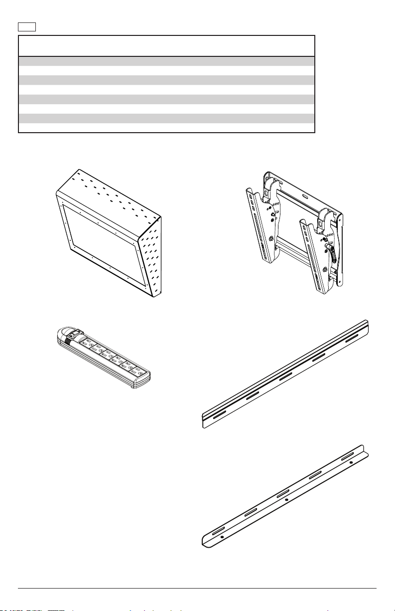
Parts (Before beginning, make sure you have all parts shown below).
Parts List
A enclosure 1 152-1544 152-1545
B wall mount 1 ST635 ST640
C #14 x 2-1/2" wood screw 4 5S1-015-C03 5S1-015-C03
D 8mm concete anchor 4 590-0320 590-0320
E power strip 1 600-0370 600-0370
F locking bracket 1 152-T1502 152-T1511
G hook on bracket 1 152-T1508 152-T1520
H M5 x 20mm 3 510-1065 510-1065
KLR62232
Part #
KLR64255
Part #Description Qty
(1)
A
enclosure
E
power strip
(1)
B
wall mount
(1)
G
hook-on
bracket
(1)
(1)
F
locking bracket
4
2019-06-14 #:150-9227-1
Page 5
(4)
C
#14 x 2-1/2" wood screw
(3)
H
M5 x 20mm
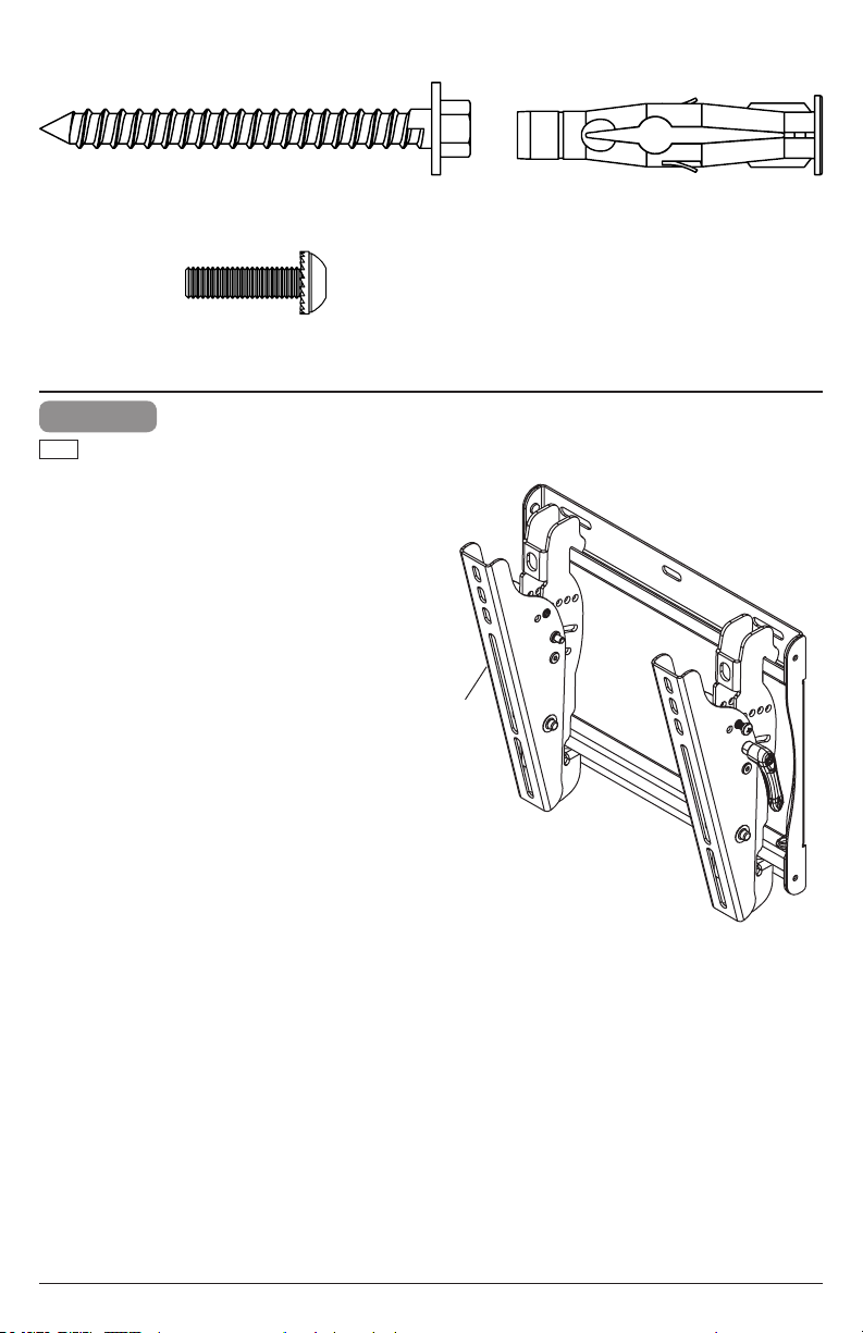
1
ENG
Follow and complete instructions for included wall
mount.
(4)
D
8mm concrete anchor
B
5
2019-06-14 #:150-9227-1
Page 6
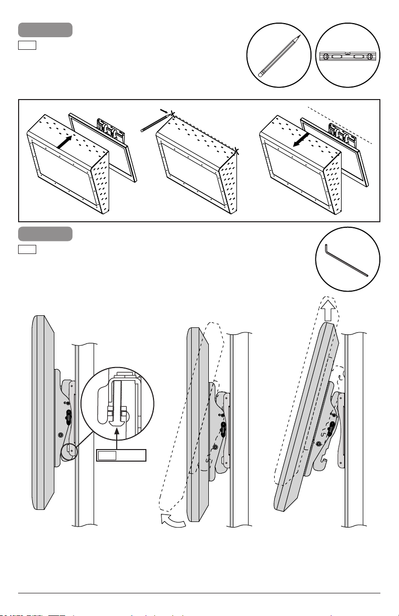
2
ENG
Hold enclosure over display in desired location,
and make sure that it is level. Mark the top
location of the enclosure.
B
A
3
ENG
Remove display.
ENG
4mm
Loosen.
6
2019-06-14 #:150-9227-1
Page 7

4
ENG
Wood stud wall.
4a
ENG
Concrete/Cinder block.
4b
4a
WARNING
ENG - When installing Peerless wall mounts on a wood stud wall covered with gypsum board (drywall), verify that
the wood studs are a minimum of 2" x 4" nominal size. Do not install over gypsum board thicker than 5/8".
ENG
4a-1
Use stud nder to locate and
mark stud center lines.
7
2019-06-14 #:150-9227-1
Page 8

4a-2
Mark mounting holes on stud center lines.
ENG
Mounting holes should be positioned 1/8" under
the horizontal cover line.
ENG
cover line
ENG
cover line
B
G
⅛"
G
B
8
2019-06-14 #:150-9227-1
Page 9

4a-3
2.5"
(64mm)
5/32"
(4mm)
Drill mounting holes into supporting surface
ENG
(2.5" (64mm) minimum depth required).
4a-4
Level wallplate. Install using wood screws provided.ENG
3/8"
(10mm)
G
C (2)
5/32"
(4mm)
ENG
Mounting hole must center on stud.
B
ENG
Maximum 80 in. • lb (9 N.M.).
5
9
2019-06-14 #:150-9227-1
Page 10

4b
WARNING
ENG - When installing Peerless wall mounts on a concrete wall, the wall must be at least 8" thick with a minimum
compressive strength of 2000 psi. When installing Peerless wall mounts on a cinder block wall, the cinder blocks
must meet ASTM C-90 specications and have a minimum nominal width of 8". Do not drill into mortar joints!
Be sure to mount in a solid part of the block, generally 1" (25 mm) minimum from the side of the block. It is
suggested that a standard electric drill on slow setting is used to drill the hole instead of a hammer drill to avoid
breaking out the back of the hole when entering a void or cavity. Never attach concrete expansion anchors to
concrete or cinder block covered with plaster, drywall or other nishing material.
4b-1
Mark mounting holes on stud center lines.
ENG
Mounting holes should be positioned 1/8" under
the horizontal cover line.
G
ENG
cover line
B
cover line
ENG
cover line
ENG
⅛"
G
4b-2
5/16"
(8mm)
Drill mounting holes into supporting surface
ENG
(2.5" (64mm) minimum depth required).
10
B
ENG
Do not drill into mortar joints.
2.5"
(64mm)
5/16"
(8mm)
2019-06-14 #:150-9227-1
Page 11

1b-34b-3
D (2)
4b-4
Level wallplate. Install using wood screws provided.ENG
ENG
Insert anchor ush to concrete.
D
3/8"
(10mm)
ENG
Maximum 80 in. • lb (9 N.M.).
C (2)
11
G
2019-06-14 #:150-9227-1
Page 12

5
Hang enclosure onto hook on bracket.ENG
G
A
6
ENG
Mark the bottom location of the enclosure.
B
G
ENG
Enclosure must fully seat
onto bracket.
GA
12
2019-06-14 #:150-9227-1
Page 13

7
ENG
Wood stud wall.
7a
ENG
Concrete/Cinder block.
7b
7a
WARNING
ENG - When installing Peerless wall mounts on a wood stud wall covered with gypsum board (drywall), verify that
the wood studs are a minimum of 2" x 4" nominal size. Do not install over gypsum board thicker than 5/8".
7a-1
23.98
(61cm)
B
1/16"
ENG
cover line
13
B
F
cover line
ENG
2019-06-14 #:150-9227-1
F
Page 14

7a-2
2.5"
(64mm)
5/32"
(4mm)
Drill mounting holes into supporting surface
ENG
(2.5" (64mm) minimum depth required).
7a-3
Level wallplate. Install using wood screws provided.ENG
3/8"
(10mm)
F
5/32"
(4mm)
ENG
Mounting hole must center on stud.
B
ENG
Maximum 80 in. • lb (9 N.M.).
14
C (2)
8
2019-06-14 #:150-9227-1
Page 15

This page intentionally left blank.ENG
15
2019-06-14 #:150-9227-1
Page 16

7b
WARNING
ENG - When installing Peerless wall mounts on a concrete wall, the wall must be at least 8" thick with a minimum
compressive strength of 2000 psi. When installing Peerless wall mounts on a cinder block wall, the cinder blocks
must meet ASTM C-90 specications and have a minimum nominal width of 8". Do not drill into mortar joints!
Be sure to mount in a solid part of the block, generally 1" (25 mm) minimum from the side of the block. It is
suggested that a standard electric drill on slow setting is used to drill the hole instead of a hammer drill to avoid
breaking out the back of the hole when entering a void or cavity. Never attach concrete expansion anchors to
concrete or cinder block covered with plaster, drywall or other nishing material.
7b-1
Mark mounting holes.
ENG
F
B
cover line
ENG
B
cover line
1/16"
ENG
7b-2
5/16"
(8mm)
Drill mounting holes into supporting surface
ENG
(2.5" (64mm) minimum depth required).
16
F
ENG
Do not drill into mortar joints.
2.5"
(64mm)
5/16"
(8mm)
2019-06-14 #:150-9227-1
Page 17

1b-37b-3
D (2)
7b-4
Level wallplate. Install using wood screws provided.ENG
ENG
Insert anchor ush to concrete.
D
3/8"
(10mm)
ENG
Maximum 80 in. • lb (9 N.M.).
17
F
C (2)
2019-06-14 #:150-9227-1
Page 18

8
9
10
ENG
ESP
FRN
DEU
NEL
ITL
ČEŠ
SLK
POR
TÜR
4mm
Tighten.
Apretar.
Serrer.
Anziehen.
Aandraaien.
Stringere.
Utáhněte.
Utiahnite.
Apertar.
Sıkmak.
18
2019-06-14 #:150-9227-1
Page 19

A
11
G
12
4mm
ENG
Do not overtighten screws.
19
H (3)
2019-06-14 #:150-9227-1
Page 20

Peerless Industries, Inc. (“Peerless-AV”) warrants to original end-users that each Peerless-AV® mounting product will be free from defects
LIMITED FIVE-YEAR WARRANTY
in material and workmanship, under normal use, for the applicable warranty period (from date of the original installation of the product).
At its option, Peerless-AV will repair or replace, or refund the purchase price of, any product which fails to conform with this warranty.
Any implied warranty of merchantability or tness for a particular purpose shall be limited to the period of the
express warranty set forth below.
In no event shall Peerless-AV be liable for incidental or consequential damages, whether or not secured by a
security device which may be included with the product.
Some states do not allow limitations on how long an implied warranty lasts, or the exclusion of incidental or consequential damages, so
the above limitation and/or the above exclusion may not apply to you.
This warranty does not cover damage caused by incorrect selection, installation or the failure to follow Peerless-AV instructions or
warnings when installing, using or storing the product.
This warranty gives specic legal rights, and you may also have other rights which vary from state to state. To make a warranty claim in
North America, contact Peerless-AV customer care at 1-800-865-2112. See complete global warranty information for regions outside North
America at www.peerless-av.com/en-uk/customer-care/warranties-returns.
Peerless-AV
2300 White Oak Circle
Aurora, IL 60502
Email: tech@peerlessmounts.com
Ph: (800) 865-2112
Fax: (800) 359-6500
www.peerless-av.com
© 2019, Peerless Industries, Inc.
Peerless-AV Europe
Unit 3 Watford Interchange,
Colonial Way, Watford, Herts,
WD24 4WP, United Kingdom
Customer Care
44 (0) 1923 200 100
www.peerless-av.com
© 2019, Peerless Industries, Inc.
Peerless-AV de Mexico
Ave de las Industrias 413
Parque Industrial Escobedo
Escobedo N.L Mexico 66062
Servicio al Cliente
01-800-849-65-77
www.peerless-av.com
© 2019, Peerless Industries, Inc.
 Loading...