

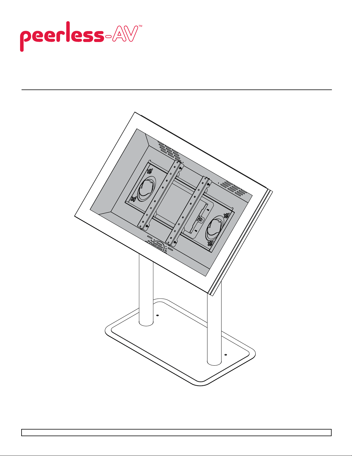
Installation and Assembly:
Indoor Digital Signage/Kiosk Enclosure - Landscape
Model: KL540-S, KL546-S, KL540-AB, KL546-AB, KL540-AW, KL546-AW
Maximum Load Capacity:
75 lb (28 kg)
1 of 7
Visit the Peerless Web Site at www.peerless-av.com For customer care call 1-800-865-2112 or 708-865-8870.
ISSUED: 03-27-12 SHEET #:125-9290-3 05-21-12
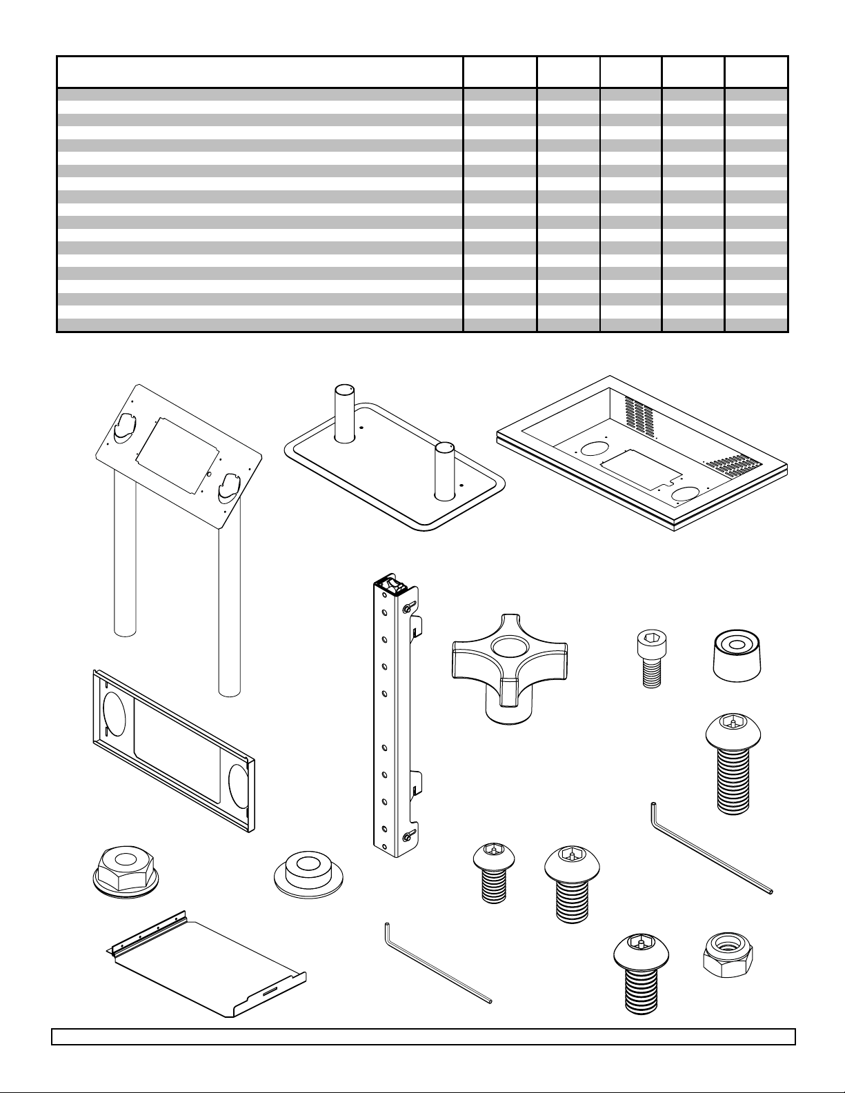
PARTS LIST KL540-S KL546-S KL540-AB KL546-AB KL540-AW KL546-AW
#
#
#
#
#
#
w
0
0
0
Description Qty. Part
A stand weldment 1 145-F4596 145-F4596 145-S1596 145-S1596 145-S2596 145-S2596
B base weldment 1 145-F4553 145-F4553 145-S1553 145-S1553 145-S2553 145-S2553
C enclosure assembly 1 145-F4600 145-F4599 145-S1600 145-S1599 145-S2600 145-S2599
D adapter plate 1 145-F4579 145-F4579 145-S1579 145-S1579 145-S2579 145-S2579
E adapter bracket 2 145-F4597 145-F4597 145-S1597 145-S1597 145-S2597 145-S2597
F 1/4-20 knob 4 560-1199 560-1199 560-1199 560-1199 560-1199 560-1199
G #8-32 socket cap screw 8 520-1210 520-1210 520-1210 520-1210 520-1210 520-1210
H rubber foot 8 590-1288 590-1288 590-1288 590-1288 590-1288 590-1288
I 1/4-20 flanged locknut 2 530-2021 530-2021 530-2021 530-2021 530-2021 530-2021
J nylon shoulder washer 4 590‐2233 590‐2233 590‐2233 590‐2233 590‐2233 590‐2233
K M6 x 12 mm socket pin screw 4 520-1050 520-1050 520-1050 520-1050 520-1050 520-1050
L M8 x 15 mm socket pin screw 4 520-1068 520-1068 520-1068 520-1068 520-1068 520-1068
M 4 mm allen wrench 1 560-9646 560-9646 560-9646 560-9646 560-9646 560-9646
N hinged door 1 145-F4598 145-F4598 145-S1598 145-S1598 145-S2598 145-S2598
O 9/64" allen wrench 1 560-9728 560-9728 560-9728 560-9728 560-9728 560-9728
P 1/4-20 x 1/2" socket pin screw 4 520-2069 520-2069 520-1054 520-1054 520-2069 520-2069
Q M4 nylock nut 2 530-9415 530-9415 530-9415 530-9415 530-9415 530-9415
R lock key (not shown) 3 565-0052A 565-0052A 565-0052A 565-0052A 565-0052A 565-0052A
S M8 x 20 socket pin scre
4 520-112
Part
520-112
Part
520-1120520-1120520-1120520-112
Part
Part
Part
D
A
B
E
C
F H
G
S
I J
K L
M
P
Q
O
N
2 of 7
Visit the Peerless Web Site at www.peerless-av.com For customer care call 1-800-865-2112 or 708-865-8870.
ISSUED: 03-27-12 SHEET #:125-9290-3 05-21-12
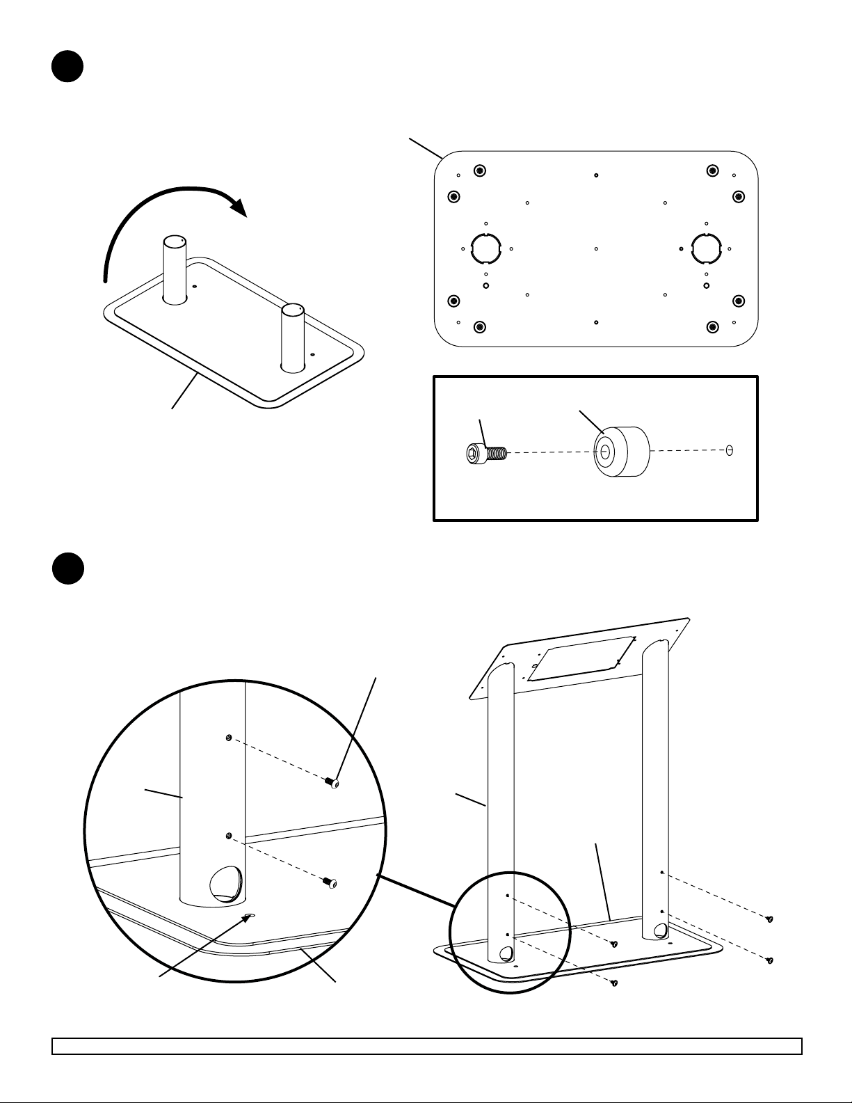
Tip base weldment (B) backward onto oor. Secure eight rubber feet (H) using eight #8-32 x 3/8” socket head cap
1
screws (G) to bottom of base weldment (B) using tool (O) as shown below.
NOTE: Do not over tighten.
B
B
BOTTOM OF BASE WELDMENT (B)
HG
Attach stand weldment (A) to base weldment (B) using four 1/4-20 socket pin screws (P).
2
NOTE: Loosely fasten all 1/4-20 socket pin screws (P), then tighten all screws using 4 mm allen wrench (M)
until stand weldment is secure.
DETAIL 1
A
P
A
B
NOTE: holes indicate
back of stand
Visit the Peerless Web Site at www.peerless-av.com For customer care call 1-800-865-2112 or 708-865-8870.
B
3 of 7
ISSUED: 03-27-12 SHEET #:125-9290-3 05-21-12
BACK

Position enclosure assembly (C), and adapter plate (D) on top of stand weldment (A).
3
Make sure that holes in enclosure assembly (C), and adapter plate (D) go over
threaded studs in stand weldment (A)
C
D
DETAIL 2
A
THREADED STUDS
Secure enclosure assembly (C) using two 1/4-20 anged locknuts (I) as shown in detail 3.
3
C
DETAIL 3
I
D A
THREADED STUDS
4 of 7
Visit the Peerless Web Site at www.peerless-av.com For customer care call 1-800-865-2112 or 708-865-8870.
ISSUED: 03-27-12 SHEET #:125-9290-3 05-21-12

Secure adapter plate (D) to enclosure assembly (C) using four 1/4-20 knobs (F) as shown in detail 4.
3
Adapter plate (D) can be adjusted vertically buy loosening 1/4-20 knobs (F) as shown in detail 4.
C
F
DETAIL 4
Attaching Hinged Door on back of Stand Weldment
NOTE: Make sure that lock is opened and positioned as shown in detail 5.
4
Position hinged door (N) inside door opening as shown in detail 5.
Position hinge on top of two threaded studs in stand weldment (A) as shown in detail 6.
Once hinged door (N) is in place, fasten two M4 nylock nuts (Q) as shown in detail 6.
Close lock.
DETAIL 5
D
F
DETAIL 6
N
N
Q
DOOR OPENING
Visit the Peerless Web Site at www.peerless-av.com For customer care call 1-800-865-2112 or 708-865-8870.
NOTE: MAKE SURE THAT
LOCK IS POSITIONED
AS SHOWN
5 of 7
DOOR THREADED STUDS
ISSUED: 03-27-12 SHEET #:125-9290-3 05-21-12

Attaching Adapter Brackets to Display
Attach adapter brackets (B) to back of display using four M6 x 12 mm socket pin screws (K) with nylon shoulder
5
washer (J), or four M8 x 15 mm socket pin screws (L), or M8 x 20 mm socket pin screws (S) as shown in detail 6.
NOTE: Some displays may have offset hole patterns. When using offset hole patterns make sure that adapter
brackets (B) are centered on back of display.
MAX VESA-600 mm
MIN VESA-200 mm
E
400 mm
300 mm
200 mm
BACK VIEW
Attach adapter brackets (E) and display onto channels on adapter
plate (D) as shown in detail 7.
Adapter Brackets (E) and display can be adjusted horizontally.
K, L, or S
J
E
TOP COVER
DISPLAY
DETAIL 6
6 of 7
Visit the Peerless Web Site at www.peerless-av.com For customer care call 1-800-865-2112 or 708-865-8870.
CHANNEL
ISSUED: 03-27-12 SHEET #:125-9290-3 05-21-12
DETAIL 7

Adapter Assembly Adjustment
Use legend below to determine position of display.
6
NOTE: Each knob can be adjusted independently for ne tuning adjustments.
Turn knob CLOCKWISE to tighten
Turn knob COUNTER-CLOCKWISE to loosen
IN
OUT
TILT FORWARD
TILT BACKWARD TILT RIGHT TILT LEFT
7 of 7
Visit the Peerless Web Site at www.peerless-av.com For customer care call 1-800-865-2112 or 708-865-8870.
ISSUED: 03-27-12 SHEET #:125-9290-3 05-21-12
 Loading...