

Page 1

GC-X360S-W
GC-X360S-B
Game Console Security
Cover for Xbox 360S
1
date:01/22/13 #:125-9401
Page 2
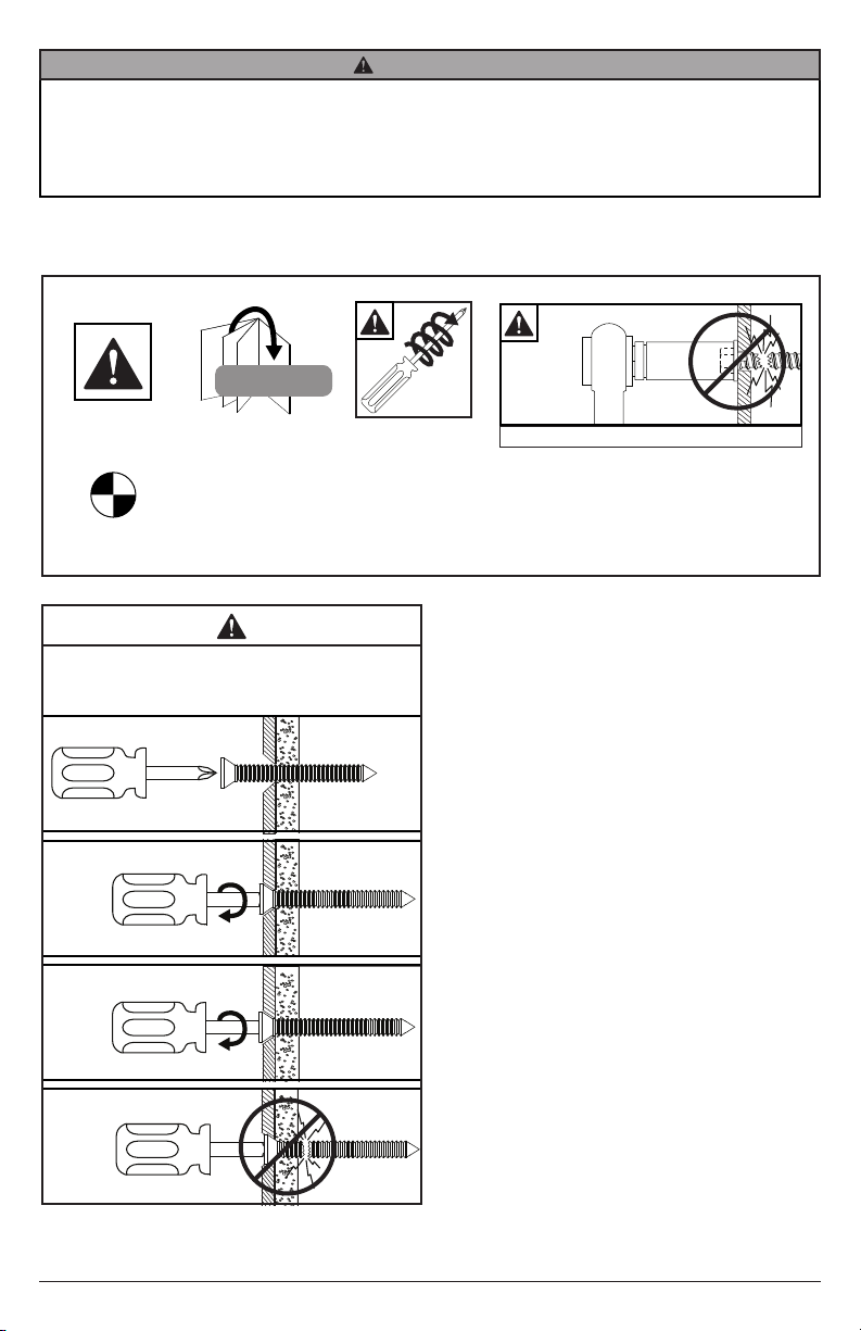
WARNING
ENG - This product was designed to be installed on wood stud, solid concrete or cinder block walls. Before installing make sure the supporting surface will support the combined load of the equipment and hardware. Screws
must be tightly secured. Do not overtighten screws or damage can occur and product may fail. Never exceed
the Maximum Load Capacity. Always use an assistant or mechanical lifting equipment to safely lift and position
equipment. This product is intended for indoor use only. Use of this product outdoors could lead to product failure
or personal injury. For support please call customer care at 1-800-865-2112.
Symbols
#
WARNING
Display
center.
To properly tighten screws: Tighten until screw head
makes contact, then tighten another 1/2 turn. Do not
overtighten screws.
Skip to step.
1
2
3
+1/2
Screws must get at
least three full turns
and t snug.
x3
Do not over tighten screws
4
2
date:01/22/13 #:125-9401
Page 3
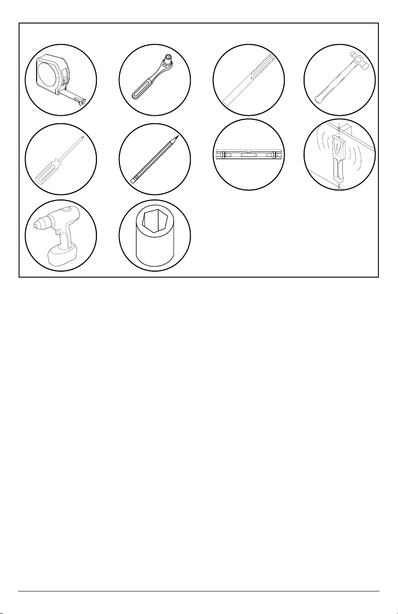
Tools Needed for Assembly.
5/16",
5/32", 1/2"
3/8"
(10mm)
3
date:01/22/13 #:125-9401
Page 4
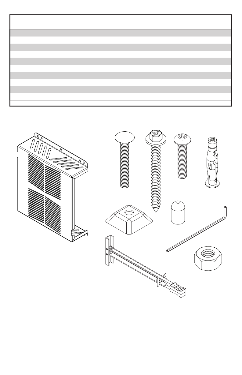
Parts List
Part Description Quantity Part Number (-B) Part Number (-W)
A
cover plate 1 125-P1455 125-2455
B
1/4-20 x 1.75" carriage bolt 4 520-1017 520-1017
C
#14 2 2.5" hex head wood screw 2 500-1005 500-1005
D
1/4-20 x 1.5" socket pin screw 4 520-1256 520-1256
E
concrete anchor 2 590-0320 590-0320
F
1/4 x 20 slope nut 3 530-0035 530-0035
G
plastic screw cap 4 590-1294 590-1294
H
4 mm allen wrench 1 560-9646 560-9646
I
1/4-20 plastic toggler 4 560-9708 560-9708
J
1/4-20 nylock nut 2 530-9413 530-9413
Before beginning, make sure you have all parts shown below
A
B
F
C
D
E
G
H
J
I
4
date:01/22/13 #:125-9401
Page 5

1
Wood stud wall.
Concrete/Cinder block.
1a
Drywall. Desktop
1c 1d
1b
5
date:01/22/13 #:125-9401
Page 6

1a
WARNING
When installing Peerless wall mounts on a wood stud wall covered with gypsum board (drywall), verify that the
woods studs are a minimum of 2”X4” nominal size. When installing to more than one stud, insure the spacing
between studs is at least 16” but does not exceed 24”. Do not install over gypsum board thicker than 5/8”.
1a-1
Use stud nder to locate and mark stud
center lines.
1a-2
Level cover plate. Mark mounting holes
on stud center lines.
6
date:01/22/13 #:125-9401
Page 7

1a-3
Drill mounting holes into supporting surface
(2.5" (64 mm) minimum depth required).
5/32"
(4mm)
1a-4
Level cover plate. Install using wood screws provided.
3/8"
(10mm)
2.5"
(64mm)
5/32"
(4mm)
Mounting hole must center on stud.
Maximum 80 in. • lb (9 N.M.).
C
2
7
date:01/22/13 #:125-9401
Page 8

1b
WARNING
ENG • When installing Peerless wall mounts on a concrete wall, the wall must be at least 8” thick with a minimum
compressive strength of 2000 psi.
• When installing Peerless wall mounts on a cinder block wall, the cinder blocks must meet ASTM C-90
specications and have a minimum nominal width of 8”. Do not drill into mortar joints! Be sure to mount in a solid
part of the block, generally 1” (25 mm) minimum from the side of the block. It is suggested that a standard electric
drill on slow setting is used to drill the hole instead of a hammer drill to avoid breaking out the back of the hole
when entering a void or cavity.
• Never attach expansion anchors to concrete or cinder block covered with plaster, drywall or other nishing
material.
1b-1
Level cover plate. Mark mounting holes.
1b-2
Drill mounting holes into supporting surface
(2.5" (64 mm) minimum depth required).
5/16"
(8mm)
2.5"
(64mm)
5/16"
(8mm)
Do not drill into mortar joints.
8
date:01/22/13 #:125-9401
Page 9

1b-31b-3
E
1b-41b-4
Level wallplate. Install using concrete
anchors and wood screws provided.
E
Insert anchor ush to concrete.
3/8"
(10mm)
Maximum 80 in. • lb (9 N.M.).
C
9
date:01/22/13 #:125-9401
Page 10

WARNING
Level cover plate and mark the center of the four mounting holes. Drill four 1/2" holes through drywall.
• Drywall must be 1/2" or thicker.
• Make sure that the wall will safely support the combined load of the equipment and all attached hardware and
components.
1c-1
NOTE: It may be necessary to drill 5/32" pilot holes prior to drilling 1/2" holes.
2.5"
(64mm)
1/2"
(12mm)
1c-2
g. 1.3
1
I
Pivot end of toggler (I).
2
I
drill
1/2"
hole
Push into hole.
3
D
I
Rotate toggler (I) clockwise to wedge it against
inside walls.
4
I
Slide plastic cap forward while pulling back
rmly on ring.
5
Break off excess.
I
10
date:01/22/13 #:125-9401
Page 11

1d-1
Level cover plate and mark the center of four
rectangular mounting holes
Drill four 5/16” (8 mm) dia. holes through desktop
ounting surface
(8 mm)
5/16"
B
BOTTOM OF DESK
NOTE: Avoid jamming both slope nuts (F) together,
doing so may make it difcult to remove slope nut
used for tightening.
After slope nut is secure remove bottom slope nut.
F
LEAVE SPACE
IN BETWEEN
SLOPE NUTS
F
BOTTOM OF DESK
TIGHTENING
SLOPE NUT B
F
F
J
B
TIGHTENING
SLOPE NUT
5/8" OPEN BOX WRENCH
11
date:01/22/13 #:125-9401
Page 12

Peerless Industries, Inc. (“Peerless”) warrants to original end-users of Peerless® products will be free from defects in material and
LIMITED FIVE-YEAR WARRANTY
workmanship, under normal use, for a period of ve years from the date of purchase by the original end-user (but in no case longer than
six years after the date of the product's manufacture). At its option, Peerless will repair or replace, or refund the purchase price of, any
product which fails to conform with this warranty.
In no event shall the duration of any implied warranty of merchantability or tness for a particular purpose be longer than the
period of the applicable express warranty set forth above. Some states do not allow limitations on how long a implied warranty lasts,
so the above limitation may not apply to you.
This warranty does not cover damage caused by (a) service or repairs by the customer or a person who is not authorized for such service
or repairs by Peerless, (b) the failure to utilize proper packing when returning the product, (c) incorrect installation or the failure to follow
Peerless' instructions or warnings when installing, using or storing the product, or (d) misuse or accident, in transit or otherwise, including
in cases of third party actions and force majeure.
In no event shall Peerless be liable for incidental or consequential damages or damages arising from the theft of any product,
whether or not secured by a security device which may be included with the Peerless® product. Some states do not allow the
exclusion or limitation of incidental or consequential damages, so the above limitation or exclusion may not apply to you.
This warranty is in lieu of all other warranties, expressed or implied, and is the sole remedy with respect to product defects. No dealer,
distributor, installer or other person is authorized to modify or extend this Limited Warranty or impose any obligation on Peerless in
connection with the safe of any Peerless® product.
This warranty gives specic legal rights, and you may also have other rights which vary from state to state.
Peerless-AV
2300 White Oak Circle
Aurora, IL 60502
Email: tech@peerlessmounts.com
Ph: (800) 865-2112
Fax: (800) 359-6500
www.peerless-av.com
© 2012, Peerless Industries, Inc.
12
date:01/22/13 #:125-9401
 Loading...