

Page 1
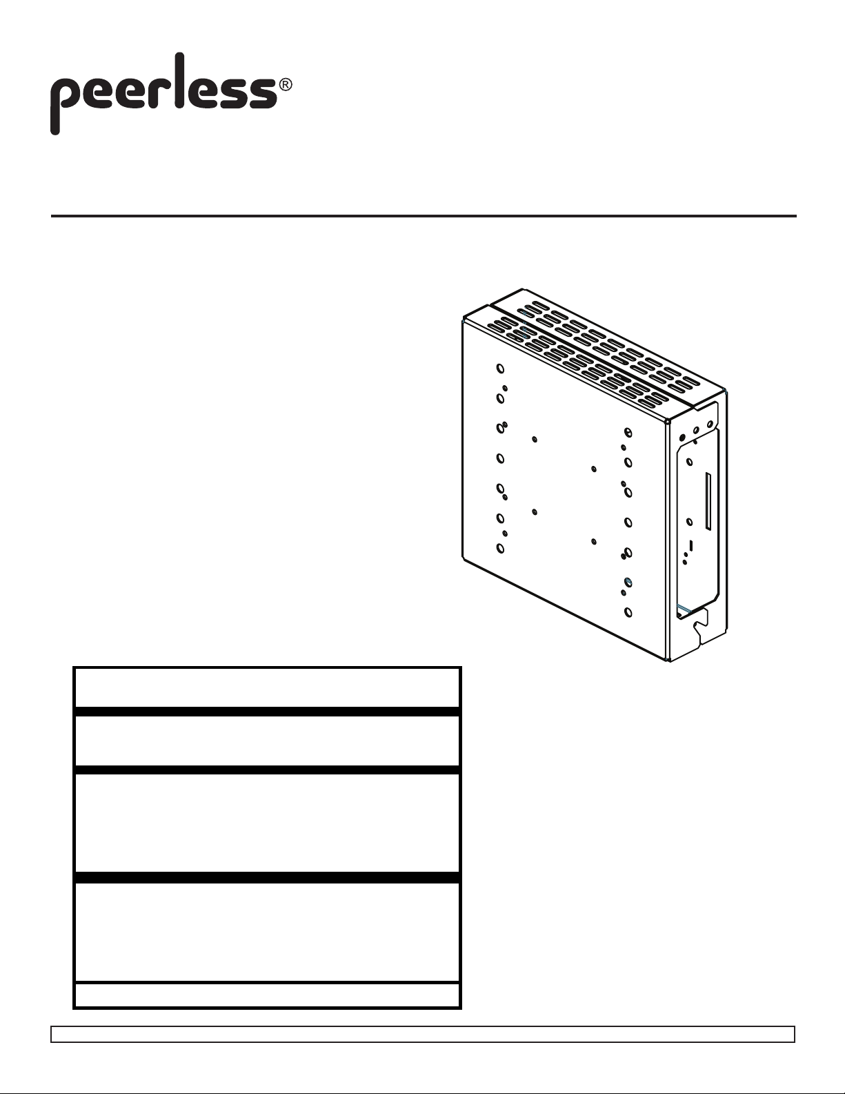
Installation and Assembly:
Wall Mount with Game Console Storage
Model: GC-UNV
When Mounting with
Model Max.Load
SP850 80lb(36kg)
FPS‐1000 80lb(36kg)
SA745PU 70lb(32kg)
SA750PU 80lb(36kg)
SA760PU 80lb(36kg)
SA770PU 80lb(36kg)
SA752PU 80lb(36kg)
SA761PU 80lb(36kg)
SA763PU 80lb(36kg)
SA771PU 80lb(36kg)
MountingDirectlytoScreen 80lb(36kg)
1 of 13
Visit the Peerless Web Site at www.peerlessmounts.com For customer care call 1-800-865-2112 or 708-865-8870.
© 2011 Peerless Industries, Inc. All rights reserved.
Peerless is a registered trademark of Peerless Industries, Inc.
Other parties’ marks are the property of their respective owners.
Peerless has no afliation with Sony Corporation of America
Microsoft , or Nintendo .
ISSUED: 01-28-11 SHEET #:125-9176-1
®®
Page 2
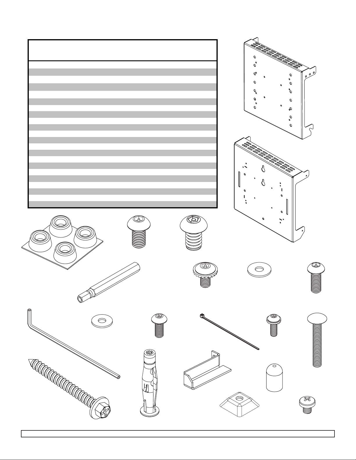
Before you begin, make sure all parts shown are included with your product.
)
Parts may appear slightly different than illustrated.
PARTS LIST
Description Qty. Part #
adapter plate 1 125-1213
A
wall plate 1 125-1214
B
rubber feet (pack of four) 1 570-1036
C
D
M8 x 15mm socket pin screw
E
M10 x 15 mm penta-pin screw
M10 penta-pin tool
F
M6 x 12 mm socket pin serrated washer head screw 4 510-1050
G
#10 flat washer 4 540-9400
H
4 mm allen wrench 1 560-9646
I
M6 x 16 mm socket pin screw
J
#8 flat washers
K
M5 x 12 mm socket pin screw
L
cable tie 4 560-9711
M
M4 x 12 mm socket pin serrated washer head screw
N
#14 x 2.5" hex head wood screw
O
concrete anchor
P
Wii™ lockdown bracket
Q
1/4-20 x 1.75" carriage bolt
R
1/4-20 slope nut 3 530-0035
S
plastic screw cap
T
M5 x 6 mm phillips screw
U
safety belt hardware (not shown
V
4 520-1068
4 520-9263
1 520-9260
4 520-1132
4 540-1001
4 520-1064
4 510-1079
3 5S1-015-C03
3 590-0320
3 125-1208
2 520-1017
2 590-1294
3 520-1023
1 170-8039-1
A
B
C D
F G H
I
K
O
P
L
E
M
Q
N
J
R
T
U
S
2 of 13
Visit the Peerless Web Site at www.peerlessmounts.com For customer care call 1-800-865-2112 or 708-865-8870.
ISSUED: 01-28-11 SHEET #:125-9176-1
Page 3
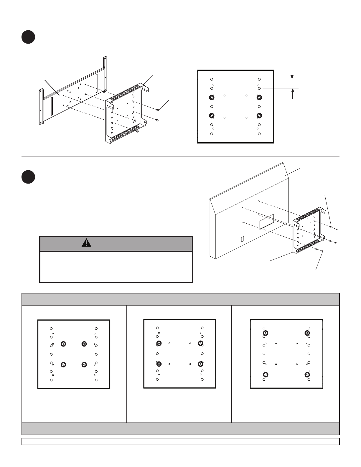
Attaching Wall Plate to dedicated adapter Plate:
Using the hole pattern shown in detail 1, attach the adapter plate (A) to dedicated adapter plate with four
1
M10 x 15 mm screws (E) as shown in gure 1.1. Tighten screws using M10 penta-pin tool (F). If attaching to
articulating mount use M10 x 15 mm screws (supplied with dedicated adapter plate).
MOUNTING PATTERN FOR
DEDICATED
ADAPTER PLATE
A
DEDICATED ADAPTER PLATES
1 5/8"
Figure. 1.1
Attaching Adapter Plate to Screen
Attaching adapter plate to screen with
1
VESA hole pattern:
Choose hole pattern and fasteners shown in detail 2 for
mounting screen with VESA mounting patterns. Hand thread
screws (N, L or G) through washers (K or H) and adapter
plate (A) into screen as shown (right). Screw must make at
least three full turns into the mounting hole and t snug into
place. Securely tighten screws using 4 mm allen wrench (I).
WARNING
• If screws don't get three complete turns in the screen
inserts or if screws bottom out and bracket is still
not tightly secured, damage may occur to screen or
product may fail.
E
TYPICAL
ADJUSTMENT
INCRAMENT
DETAIL 1
SCREEN
K or H
A
N, L or G
MOUNTING PATTERNS
VESA® 200 x 100 VESA® 200 x 200VESA® 100 x 100
M4 x 12 mm screws (N) with #8
washers (K) or M5 x 12 mm screws
(L) with #10 washers (H)
M4 x 12 mm screws (N) with #8
washers (K), M5 x 12 mm screws (L)
M4 x 12 mm screws (N) with #8
washers (K) or
M6 x 12 mm screws (G) with
#10 washers (H)
DETAIL 2
3 of 13
Visit the Peerless Web Site at www.peerlessmounts.com For customer care call 1-800-865-2112 or 708-865-8870.
ISSUED: 01-28-11 SHEET #:125-9176-1
Page 4
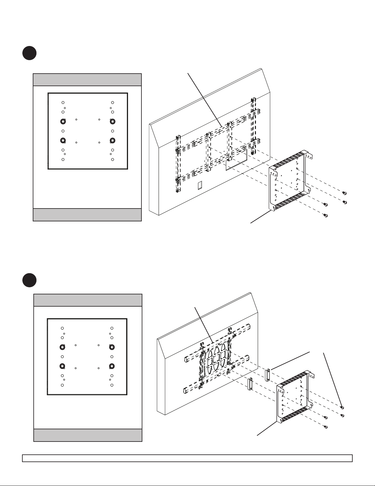
Attaching Adapter Plate to SA745PU, SA750PU, SA760PU, SA770PU
Universal Adapter Bracket
Secure adapter plate (A) to universal adapter bracket with four M10 x 15 mm screws (supplied with universal
1
adapter bracket) as shown below.
UNIVERSAL ADAPTER BRACKET
MOUNTING PATTERN
M10 x 15 mm
(supplied with
universal adapter bracket)
A
M10 X 15 MM SCREW
(UNIVERSAL ADAPTER BRACKET)
Attaching adapter Plate to SA752PU, SA761PU, SA763PU, SA771PU
(ACC950 Required) Universal Adapter Bracket
Secure adapter plate (A) to universal adapter bracket with four M10 x 40 mm screws (supplied with ACC950) as
1
shown in below.
MOUNTING PATTERN
UNIVERSAL ADAPTER BRACKET
ACC-950 SPACER AND
M10 X 40 MM SCREWS
(SUPPLIED WITH ACC950)
M10 x 40 mm
(supplied with ACC950)
A
4 of 13
Visit the Peerless Web Site at www.peerlessmounts.com For customer care call 1-800-865-2112 or 708-865-8870.
ISSUED: 01-28-11 SHEET #:125-9176-1
Page 5

PlayStation® 3 and XBOX 360™ Installation
Secure four rubber feet (C) to wall plate (B)
5
in approximate position as shown below.
GAME CONSOLE
(X-BOX360™ SHOWN BELOW)
B
C
TM
Press game console against wall plate (B) and tightly
secure safety belt hardware (V).
B
V
TM
GAME CONSOLE MAY APPEAR
DIFFERENT THAN ILLUSTRATED
Wii™ Installation
Secure four rubber feet (C) to wall plate (B)
in approximate position as shown below.
Secure Wii™ game console in place with three
lockdown brackets (Q) using three
M5 x 6 mm phillips screws (U).
B
MOUNTING PATTERN
C
M5 x 6 mm phillips screws (U)
USE TO FACE Wii™ RIGHT
Q
W ™ GAME CONSOLE ii
U
5 of 13
Visit the Peerless Web Site at www.peerlessmounts.com For customer care call 1-800-865-2112 or 708-865-8870.
ISSUED: 01-28-11 SHEET #:125-9176-1
Page 6

Select Mounting Application
3
Installation to Articulating Mounts....................................Continue Below Step 4
Installation to Wood Stud Wall................................................................PAGE 9
Installation to Solid Concrete or Cinder Block Wall.............................PAGE 10
Installation to Desktop Mounting Surface.............................................PAGE 11
Attaching Adapter Plate to Wall Plate
Fasten two M8 x 15 mm screws (D) into wall plate
4
(B) leaving 1/8" of exposed thread using 4 mm
allen wrench (I) as shown below.
B
Hook adapter plate (A) onto exposed M8 x 15 mm
screws, and secure using two M8 x 15 mm screws
(D) using 4 mm allen wrench (I) as shown below.
Tighten all screws.
A
D
B
D
Visit the Peerless Web Site at www.peerlessmounts.com For customer care call 1-800-865-2112 or 708-865-8870.
1/8"
6 of 13
M8 X 15 MM SCREW
ISSUED: 01-28-11 SHEET #:125-9176-1
Page 7

Attaching Wall Plate to SP850, FPS-1000
Thread two M10 x 15 mm penta-pin screws (E) into top
5
holes of wall plate (B) leaving 1/8" space between head
of screw and wall plate as shown below.
Hook wall plate (B) and two exposed M10 x 15 mm
penta-pin screws (E) into keyhole slots on mount.
B
E
KEYHOLE SLOT
E
1/8"
Secure with two M10 x 15 mm penta-pin screws (E)
using M10 penta-pin tool (F) as shown below.
E
Attaching Wall Plate to SA752PU, SA761PU, SA763PU, SA771PU
Thread two M10 x 15 mm penta-pin screws (E) into top
5
holes of wall plate (B) leaving 1/8" space between head
of screw and wall plate as shown below.
Hook wall plate (B) and two exposed M10 x 15 mm
penta-pin screws (E) into keyhole slots on mount.
Secure with two M10 x 15 mm penta-pin screws (E)
using M10 penta-pin tool (F) as shown below.
B
1/8"
E
KEYHOLE SLOT
7 of 13
Visit the Peerless Web Site at www.peerlessmounts.com For customer care call 1-800-865-2112 or 708-865-8870.
ISSUED: 01-28-11 SHEET #:125-9176-1
E
Page 8

Attaching Adapter Plate to SA745PU, SA750PU, SA760PU, SA770PU
Remove two M5 x 20 mm screws from the rollbrake. Lift adapter plate of wall arm mount out from tilt bracket as
5
shown.
NOTE: M5 X 25 mm screw may need to be loosened a few turns to allow adapter bracket to be removed using 4
mm allen wrench (N).
M5 X 20 MM SCREW
ROLL BRAKE
WALL ARM MOUNT
ADAPTER PLATE
TILT BRACKET
Secure adapter plate of wall arm mount to wall plate (A) with
four M10 x 15 mm penta-pin screws (E) using M10 penta-pin
tool (F) as shown below.
M5 X 25 MM SCREW
B
A
Insert the puck of adapter plate into the tilt
bracket slot as shown. Attach brake pad assembly so
that the brake pad is snug against the adapter plate.
Adjust roll position of adapter plate to level screen then
lock puck in place by tightening M5 x 25 mm screw on
the underside of tilt bracket.
Tighten all (M5 x 20 mm, M5 x 25 mm) screws.
M5 X 20 MM SCREW
ROLL BRAKE
ADAPTER PLATE
TILT BRACKET
WALL ARM MOUNT
E
ADAPTER PLATE
8 of 13
Visit the Peerless Web Site at www.peerlessmounts.com For customer care call 1-800-865-2112 or 708-865-8870.
M5 X 25 MM SCREW
ISSUED: 01-28-11 SHEET #:125-9176-1
Page 9

Installation to Wood Stud Wall
WARNING
• Installer must verify that the supporting surface will safely support the combined load of the equipment and all
attached hardware and components.
• Tighten wood screws so that wall plate is rmly attached, but do not overtighten. Overtightening can damage the
screws, greatly reducing their holding power.
• Never tighten in excess of 80 in. • lb (9 N.M.).
• Make sure that mounting screws are anchored into the center of the stud. The use of an "edge to edge" stud nder
is highly recommended.
• Hardware provided is for attachment of mount through standard thickness drywall or plaster into wood studs. Installers are responsible to provide hardware for other types of mounting situations
Use a stud nder to locate the edges of the stud. Use of an edge-to-edge stud nder is highly recommended.
4
Based on their edges, draw a vertical line down each stud center. Place wall plate (B) on wall as a template. Level,
and mark the center of the three mounting holes. Make sure that the mounting holes are on the stud center lines.
Drill three 5/32" (4 mm) dia. holes 2.5" (64 mm) deep. Fasten two #14 x 2.5" wood screws (O) leaving 1/4" of
thread exposed as shown in Figure 4.1.
Hook wall plate (B) onto exposed #14 x 2.5" wood screws (O). Secure using one #14 x 2.5" wood screws (O) as
shown in gure 4.2
Skip to Step 5.
O
1/4"
Figure 4.1
B
O
Figure 4.2
9 of 13
Visit the Peerless Web Site at www.peerlessmounts.com For customer care call 1-800-865-2112 or 708-865-8870.
ISSUED: 01-28-11 SHEET #:125-9176-1
Page 10

Installation to Solid Concrete or Cinder Block
WARNING
• When installing Peerless wall mounts on cinder block, verify that you have a minimum of 1-3/8" (35 mm) of actual concrete thickness in the hole to be used for the concrete anchors. Do not drill into mortar joints! Be sure to mount in a solid
part of the block, generally 1" (25 mm) minimum from the side of the block. Cinder block must meet ASTM C-90 specica-
tions. It is suggested that a standard electric drill on slow setting is used to drill the hole instead of a hammer drill to avoid
breaking out the back of the hole when entering a void or cavity.
• Concrete must be 2000 psi density minimum. Lighter density concrete may not hold concrete anchor.
• Make sure that the wall will safely support four times the combined load of the equipment and all attached hardware and
components.
Place wall plate (B) on wall as a template. Level, and mark the center of the three mounting holes. Drill three 5/16"
4
(8 mm) dia. holes to a minimum depth of 2.5" (64 mm). Insert anchors (P) in holes ush with wall as shown. Fasten
two #14 x 2.5" wood screws (O) leaving 1/4" of thread exposed as shown in Figure 4.3.
Hook wall plate (B) onto exposed #14 x 2.5" wood screws (O). Secure using one #14 x 2.5" wood screws (O) as
shown in gure 4.4. Skip to Step 5.
SOLID CONCRETE
SOLID CONCRETE
CINDER BLOCK
1/4"
P
O
Figure. 4.3
WARNING
• Tighten screws so that wall plate is rmly attached,
but do not overtighten. Overtightening can damage
screws, greatly reducing their holding power.
• Never tighten in excess of 80 in. • lb (9 N.M.).
• Always attach concrete expansion anchors directly
to load-bearing concrete.
• Never attach concrete expansion anchors to
concrete covered with plaster, drywall, or other
nishing material. If mounting to concrete surfaces
covered with a nishing surface is unavoidable,
the nishing surface must be counterbored as
shown below. Be sure concrete anchors do not
pull away from concrete when tightening screws. If
plaster/drywall is thicker than 5/8" (16 mm), custom
fasteners must be supplied by installer.
CINDER BLOCK
O
B
Figure. 4.4
1
concrete
surface
P
Drill holes and insert anchors (P).
2
Place plate (B) over anchors (P) and secure with screws (O).
B
O
P
INCORRECT CORRECT
wall
plate
plaster/
CUTAWAY VIEW
Visit the Peerless Web Site at www.peerlessmounts.com For customer care call 1-800-865-2112 or 708-865-8870.
dry wall
concrete
wall
plate
plaster/
dry wall
concrete
10 of 13
3
Tighten all fasteners.
ISSUED: 01-28-11 SHEET #:125-9176-1
Page 11

Mounting Surface Lock down Installation
Place wall plate (B) onto mounting surface as a template. Level, and mark the center of two rectangular mounting
4
holes. Drill two 5/16” (8 mm) dia. holes through mounting surface. Secure using two carriage bolts (R) through wall
plate (B) and mounting surface as shown in gure 4.1.
Hand tighten slope nut (S) through 1/4-20 x 1 3/4" carriage bolt (R) until snug against bottom of desktop surface as
shown in gure 4.2.
Thread another slope nut (S) upside-down, about two turns from rst slope nut (S). Insert a open box wrench
between both slope nuts (S) and tighten. NOTE: Avoid jamming both slope nuts (S) together, doing so may make it
difcult to remove slope nut used for tightening rst slope nut (S) as shown in gure 4.3.
After slope nut is secure remove bottom slope nut and add plastic cap (T) as shown in gure 4.4.
Repeat with remaining 1/4-20 x 1 3/4" carriage bolt (R).
TOP OF MOUNTING SURFACE
R
BOTTOM OF MOUNTING SURFACE
B
Figure. 4.1
R
S
Figure. 4.2 Figure. 4.3
Visit the Peerless Web Site at www.peerlessmounts.com For customer care call 1-800-865-2112 or 708-865-8870.
S
TIGHTENING
SLOPE NUT
11 of 13
S
Figure. 4.4
ISSUED: 01-28-11 SHEET #:125-9176-1
R
T
Page 12

PlayStation® 3 and XBOX 360™ Installation
Secure four rubber feet (C) to wall plate (B)
5
in approximate position as shown below.
GAME CONSOLE
(X-BOX360™ SHOWN BELOW)
B
C
TM
Press game console against wall plate (B) and tightly
secure safety belt hardware (V).
B
V
TM
GAME CONSOLE MAY APPEAR
DIFFERENT THAN ILLUSTRATED
Wii™ Installation
Secure four rubber feet (C) to wall plate (B)
in approximate position as shown below.
Secure Wii™ game console in place with three
lockdown brackets (Q) using three
M5 x 6 mm phillips screws (U).
B
MOUNTING PATTERN
C
M5 x 6 mm phillips screws (U)
USE TO FACE Wii™ RIGHT
W ™ GAME CONSOLE
Q
ii
U
12 of 13
Visit the Peerless Web Site at www.peerlessmounts.com For customer care call 1-800-865-2112 or 708-865-8870.
ISSUED: 01-28-11 SHEET #:125-9176-1
Page 13

Fasten two M8 x 15 mm screws (D) into wall plate
6
(B) leaving 1/8" of exposed thread using 4 mm
allen wrench (I) as shown below.
B
Hook adapter plate (A) onto exposed M8 x 15 mm
screws, and secure using two M8 x 15 mm screws
(D) using 4 mm allen wrench (I) as shown below.
Tighten all screws.
A
D
1/8"
Accessing Game Console
Loosen top bottom M8 x 15 mm screws (E) 1/4 turn and temporarily remove top two M8 x 15 mm screws (D) on
7
adapter plate (A) to remove screen as shown below.
REMOVE
SCREEN
D
M8 X 15 MM SCREW
A
REMOVE
B
Figure 7.1
B
LOOSEN 1/4 TURN ON
BOTH SIDES
13 of 13
Visit the Peerless Web Site at www.peerlessmounts.com For customer care call 1-800-865-2112 or 708-865-8870.
Peerless is a registered trademark of Peerless Industries, Inc. Other parties’ marks are the property of their respective owners.
ISSUED: 01-28-11 SHEET #:125-9176-1
© 2011 Peerless Industries, Inc. All rights reserved.
 Loading...