


Includes
Teacher's Notes
and
Typical
Experiment Results
Instruction Manual and Experiment Guide for the PASCO scientific
Model TD-8553/8554A/8555
012-04695D
03/99
|
|
|
|
|
|
|
|
THERMAL |
|
||||
RADIATION SYSTEM |
|||||||||||||
|
|
|
|
|
|
|
|
|
|
|
|
TD-8554A Radiation Cube |
|
|
|
|
|
|
|
|
|
|
|
|
|
(Leslie's Cube) |
|
|
|
|
|
|
|
|
|
|
|
|
|
|
TD-8555 |
|
|
|
|
|
|
|
|
|
|
|
|
|
STEFAN-BOLTZMAN |
|
|
|
|
|
|
|
|
|
|
|
|
|
LAMP |
|
|
|
|
|
|
|
|
|
|
|
|
|
CAUTION |
|
|
|
|
|
|
|
|
|
|
|
|
|
13 VDC MAX LAMP VOLTAGE |
|
|
|
|
|
|
|
|
|
|
|
TO |
R |
FOR MAXIMUM ACCURACY, |
|
|
|
|
|
|
|
|
|
RM |
IS |
|
MEASURE VOLTAGE AT |
|
|
|
|
|
|
|
|
|
N THE |
|
|
|
BINDING POSTS |
|
|
|
|
|
|
|
IO |
|
|
|
|
|||
|
|
|
|
|
|
|
|
|
|
|
|
||
|
|
|
|
|
T |
! |
|
|
|
|
4A |
|
|
|
|
|
|
|
U |
T |
|
|
|
|
USE NO.1196 BULB |
||
CAUTION: HOT! |
|
|
100W |
A |
|
|
|
|
D- |
855 |
|||
|
|
C HO |
|
|
M |
odelT |
|
|
|||||
|
4 |
5 |
BULB |
|
|
|
|
|
|
|
|
|
|
|
MAX. |
|
|
|
|
|
|
|
|
CUBE) |
|
||
ON |
3 |
|
6 |
|
|
|
|
(LESLIE'S |
|
|
|||
|
|
|
|
|
|
|
|
|
|||||
|
2 |
|
7 |
|
|
|
|
|
|
|
|
|
TD-8555 Stefan |
OFF |
1 |
|
8 |
|
|
|
|
|
|
|
|
|
|
LOW |
|
HIGH |
|
|
|
|
|
|
|
|
|
Boltzman Lamp |
|
|
|
|
|
|
|
|
|
|
|
|
|||
|
|
|
|
|
|
|
|
|
|
|
|
|
|
|
|
|
|
|
|
|
|
TD-8553 Radiation Sensor |
|
||||
© 1988 PASCO scientific |
$5.00 |
Thermal Radiation |
012-04695D |
The lightning flash with arrowhead, withinanequilateraltriangle,isintended to alert the user of the presence of uninsulated “dangerous voltage” within the product’s enclosure that may be of sufficient magnitude to constitute a risk of electric shock to persons.
CAUTION
RISK OF ELECTRIC SHOCK
DO NOT OPEN
CAUTION:
TO PREVENT THE RISK OF ELECTRIC SHOCK, DO NOT REMOVE BACK COVER. NO USER SERVICEABLE PARTS INSIDE. REFER SERVICING TO QUALIFIED SERVICE PERSONNEL.
The exclamation point within an equilateral triangle is intended to alert the user of the presence of important operating and maintenance (servicing) instructions in the literature accompanying the appliance.
2

012-04695D |
Thermal Radiation System |
|
|
Table of Contents
Section ...................................................................................................... |
|
Page |
Copyright and Warranty, Equipment Return .................................................. |
|
ii |
Introduction ..................................................................................................... |
|
1 |
Radiation Sensor .............................................................................................. |
|
1 |
Thermal Radiation Cube (Leslie’s Cube) ........................................................ |
|
2 |
Stefan-Boltzmann Lamp .................................................................................. |
|
3 |
Experiments: |
|
|
Experiment 1: Introduction to Thermal Radiation ................................... |
|
5 |
Experiment 2: Inverse Square Law .......................................................... |
|
9 |
Experiment 3: Stefan-Boltzmann Law (high temperature) |
..................... 13 |
|
Experiment 4: Stefan-Boltzmann Law (low temperature) ..................... |
17 |
|
Teacher’s Guide ............................................................................................. |
|
19 |
Technical Support ................................................................ |
Inside Back Cover |
|
i

Thermal Radiation System |
012-04695D |
Copyright, Warranty, and Equipment Return
Please— Feel free to duplicate this manual subject to the copyright restrictions below.
Copyright Notice
The PASCO scientific Model TD 8553/
8554A/8555 Thermal Radiation System manual is copyrighted and all rights reserved. However, permission is granted to non-profit educational institutions for reproduction of any part of the manual providing the reproductions are used only for their laboratories and are not sold for profit. Reproduction under any other circumstances, without the written consent of PASCO scientific, is prohibited.
Limited Warranty
PASCO scientific warrants the product to be free from defects in materials and workmanship for a period of one year from the date of shipment to the customer. PASCO will repair or replace at its option any part of the product which is deemed to be defective in material or workmanship. The warranty does not cover damage to the product caused by abuse or improper use. Determination of whether a product failure is the result of a manufacturing defect or improper use by the customer shall be made solely by PASCO scientific. Responsibility for the return of equipment for warranty repair belongs to the customer. Equipment must be properly packed to prevent damage and shipped postage or freight prepaid. (Damage caused by improper packing of the equipment for return shipment will not be covered by the warranty.) Shipping costs for returning the equipment after repair will be paid by PASCO scientific.
Credits
This manual authored by: Bruce Lee
Teacher’s guide written by: Eric Ayres
Equipment Return
Should the product have to be returned to PASCO scientific for any reason, notify PASCO scientific by letter, phone, or fax BEFORE returning the product. Upon notification, the return authorization and shipping instructions will be promptly issued.
ä NOTE: NO EQUIPMENT WILL BE ACCEPTED FOR RETURN WITHOUT AN AUTHORIZATION FROM PASCO.
When returning equipment for repair, the units must be packed properly. Carriers will not accept responsibility for damage caused by improper packing. To be certain the unit will not be damaged in shipment, observe the following rules:
The packing carton must be strong enough for the item shipped.
Make certain there are at least two inches of packing material between any point on the apparatus and the inside walls of the carton.
Make certain that the packing material cannot shift in the box or become compressed, allowing the instrument come in contact with the packing carton.
Address: |
PASCO scientific |
|
10101 Foothills Blvd. |
|
Roseville, CA 95747-7100 |
Phone: |
(916) 786-3800 |
FAX: |
(916) 786-3292 |
email: |
techsupp@pasco.com |
web: |
www.pasco.com |
ii
012-04695D |
Thermal Radiation System |
|
|
Introduction
The PASCO Thermal Radiation System includes three items: the TD-8553 Radiation Sensor, the TD-8554A Radiation Cube (Leslie's Cube), and the TD-8555 Stefan-Boltzmann Lamp. This manual contains operating instructions for each of these items plus instructions and worksheets for the following four experiments:
Introduction to Thermal Radiation,
Inverse Square Law,
Stefan-Boltzmann Law* (at high temperatures),
Stefan-Boltzmann Law* (at low temperatures).
*The Stefan-Boltzmann law states that the radiant energy per unit area is proportional to the fourth power of the temperature of the radiating surface.
In addition to the equipment in the radiation system, several standard laboratory items, such as power supplies and meters are needed for most experiments. Check the experiment section of this manual for information on required equipment.
If you don't have all the items of the radiation system, read through the operating instructions for the equipment you do have, then check the experiment section to determine which of the experiments you can perform. (A radiation sensor is required for all the experiments.)
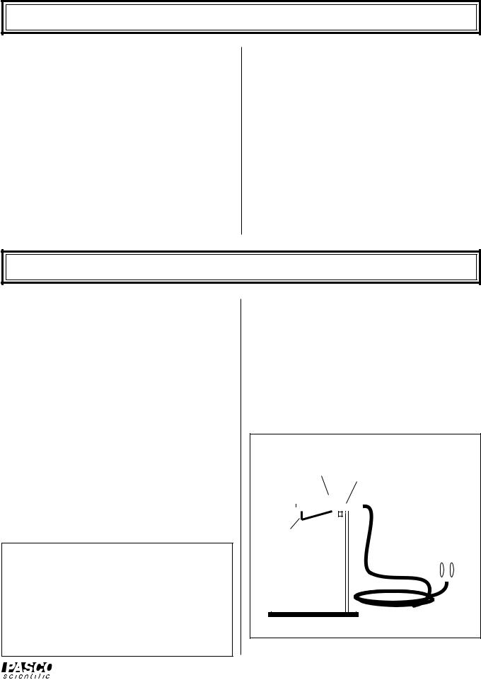
Radiation Sensor
The PASCO TD-8553 Radiation Sensor (Figure 1) measures the relative intensities of incident thermal radiation. The sensing element, a miniature thermopile, produces a voltage proportional to the intensity of the radiation. The spectral response of the thermopile is essentially flat in the infrared region (from 0.5 to 40 µm), and the voltages produced range from the microvolt range up to around 100 millivolts. (A good millivolt meter is sufficient for all the experiments described in this manual. See the current PASCO catalog for recommended meters.)
The Sensor can be hand held or mounted on its stand for more accurate positioning. A spring-clip shutter is opened and closed by sliding the shutter ring forward or back. During experiments, the shutter should be closed when measurements are not actively being taken. This helps reduce temperature shifts in the thermopile reference junction which can cause the sensor response to drift.
ä NOTE: When opening and closing the shutter, it is possible you may inadvertently change the sensor position. Therefore, for experiments in which the sensor position is critical, such as Experiment 3, two small sheets of opaque insulating foam have been provided. Place this heat shield in front of the sensor when measurements are not actively being taken.
The two posts extending from the front end of the Sensor protect the thermopile and also provide a reference for positioning the sensor a repeatable distance from a radiation source.
Specifications
Temperature Range: -65 to 85 °C. Maximum Incident Power: 0.1 Watts/cm2. Spectral Response: .6 to 30 m.
Signal Output: Linear from 10-6 to 10-1 Watts/cm2.
Shutter Ring: Slide |
|
Thumbscrew: Loosen to |
||||||||
|
reposition Sensor or to |
|||||||||
forward to open |
|
|||||||||
|
remove Sensor from stand |
|||||||||
shutter |
|
|||||||||
|
|
|
|
|||||||
|
|
|
|
|
|
|
|
|
|
|
|
|
|
|
|
|
|
|
|
|
|
|
|
|
|
|
|
|
|
|
|
|
|
|
|
|
|
|
|
|
|
|
|
|
|
|
|
|
|
|
|
|
||
Shutter |
|
|
|
|
||||||
|
|
|
|
|
|
|
|
|
|
|
|
|
|
|
|
|
|
|
|
|
|
Banana Connectors:
Connect to millivolt meter
Figure 1 Radiation Sensor
1
Thermal Radiation System |
012-04695D |
|
|
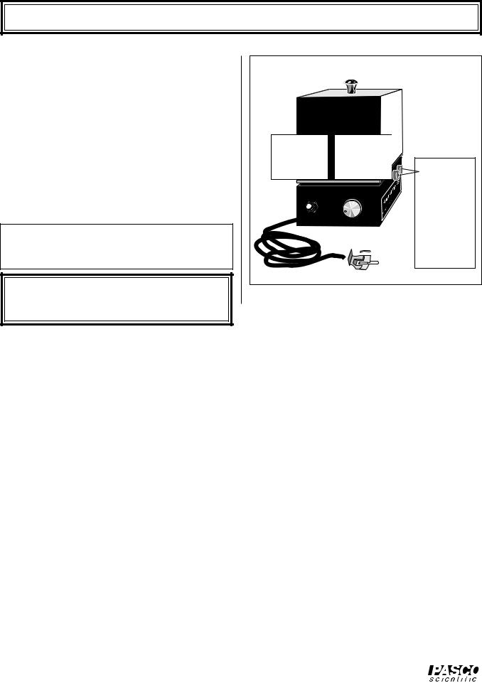
Thermal Radiation Cube (Leslie’s Cube)
The TD-8554A Radiation Cube (Figure 2) provides four different radiating surfaces that can be heated from room temperature to approximately 120 °C. The cube is heated by a 100 watt light bulb. Just plug in the power cord, flip the toggle switch to “ON”, then turn the knob clockwise to vary the power.
Measure the cube temperature by plugging your ohmmeter into the banana plug connectors labeled THERMISTOR. The thermistor is embedded in one corner of the cube. Measure the resistance, then use Table 1, below, to translate the resistance reading into a temperature measurement. An abbreviated version of this table is printed on the base of the Radiation Cube.
äNOTE: For best results, a digital ohmmeter should be used. (See the current PASCO catalog for recommended meters.)
äIMPORTANT: When replacing the light bulb, use a 100-Watt bulb. Bulbs of higher power could damage the cube.
CAUTION: Cube may be HOT!
Flip toggle switch to “ON” to turn on power.
CAUTION: HOT!
ON
OFF
Turn knob clockwise to increase temperature.
|
|
|
IO |
N |
|
|
|
T |
|
||
|
|
U |
T |
! |
|
|
100W |
A |
|
|
|
|
C HO |
|
|
|
|
4 5 |
BULB |
|
|
|
|
MAX. |
|
|
|
|
|
3 |
6 |
|
|
|
|
2 |
7 |
|
|
|
|
1 |
8 |
|
|
|
|
LOW HIGH
|
|
OR |
|
IST |
|
|
|
THERM |
|
|
|
|
|
A |
|
|
|
54 |
|
|
-85 |
|
|
elTD |
|
|
|
od |
|
|
) |
M |
|
BE |
|
|
|
|
|
|
|
CU |
|
SL |
IE |
|
|
(LE |
|
|
|
To 115 

 or
or
 200 VAC
Banana Connectors:
Measure thermistor resistance. Use table on back to determine cube temperature.
Figure 2 Radiation Cube (Leslie's Cube)
Table 1
Resistance versus Temperature for the Thermal Radiation Cube
Therm. |
Temp. |
Therm. |
Temp. |
Therm. |
Temp. |
Therm. |
Temp. |
Therm. |
Temp. |
Therm. |
Temp. |
Res. (Ω) (°C) |
Res. (Ω) (°C) |
Res. (Ω) (°C) |
Res. (Ω) (°C) |
Res. (Ω) |
(°C) |
Res. (Ω) (°C) |
|||||
|
|
|
|
|
|
|
|
|
|
|
|
|
|
|
|
|
|
|
|
|
|
|
|
207,850 |
10 |
66,356 |
34 |
24,415 |
58 |
10,110 |
82 |
4,615.1 |
106 |
2,281.0 |
130 |
197,560 |
11 |
63,480 |
35 |
23,483 |
59 |
9,767.2 |
83 |
4,475.0 |
107 |
2,218.3 |
131 |
187,840 |
12 |
60,743 |
36 |
22,590 |
60 |
9,437.7 |
84 |
4,339.7 |
108 |
2,157.6 |
132 |
178,650 |
13 |
58,138 |
37 |
21,736 |
61 |
9,120.8 |
85 |
4,209.1 |
109 |
2,098.7 |
133 |
169,950 |
14 |
55,658 |
38 |
20,919 |
62 |
8,816.0 |
86 |
4,082.9 |
110 |
2,041.7 |
134 |
161,730 |
15 |
53,297 |
39 |
20,136 |
63 |
8,522.7 |
87 |
3,961.1 |
111 |
1,986.4 |
135 |
153,950 |
16 |
51,048 |
40 |
19,386 |
64 |
8,240.6 |
88 |
3,843.4 |
112 |
1,932.8 |
136 |
146,580 |
17 |
48,905 |
41 |
18,668 |
65 |
7,969.1 |
89 |
3,729.7 |
113 |
1,880.9 |
137 |
139,610 |
18 |
46,863 |
42 |
17,980 |
66 |
7,707.7 |
90 |
3,619.8 |
114 |
1,830.5 |
138 |
133,000 |
19 |
44,917 |
43 |
17,321 |
67 |
7,456.2 |
91 |
3,513.6 |
115 |
1,781.7 |
139 |
126,740 |
20 |
43,062 |
44 |
16,689 |
68 |
7,214.0 |
92 |
3,411.0 |
116 |
1,734.3 |
140 |
120,810 |
21 |
41,292 |
45 |
16,083 |
69 |
6,980.6 |
93 |
3,311.8 |
117 |
1,688.4 |
141 |
115,190 |
22 |
39,605 |
46 |
15,502 |
70 |
6,755.9 |
94 |
3,215.8 |
118 |
1,643.9 |
142 |
109,850 |
23 |
37,995 |
47 |
14,945 |
71 |
6,539.4 |
95 |
3,123.0 |
119 |
1,600.6 |
143 |
104,800 |
24 |
36,458 |
48 |
14,410 |
72 |
6,330.8 |
96 |
3,033.3 |
120 |
1,558.7 |
144 |
100,000 |
25 |
34,991 |
49 |
13,897 |
73 |
6,129.8 |
97 |
2,946.5 |
121 |
1,518.0 |
145 |
95,447 |
26 |
33,591 |
50 |
13,405 |
74 |
5,936.1 |
98 |
2,862.5 |
122 |
1,478.6 |
146 |
91,126 |
27 |
32,253 |
51 |
12,932 |
75 |
5,749.3 |
99 |
2,781.3 |
123 |
1,440.2 |
147 |
87,022 |
28 |
30,976 |
52 |
12,479 |
76 |
5,569.3 |
100 |
2,702.7 |
124 |
1,403.0 |
148 |
83,124 |
29 |
29,756 |
53 |
12,043 |
77 |
5,395.6 |
101 |
2,626.6 |
125 |
1,366.9 |
149 |
79,422 |
30 |
28,590 |
54 |
11,625 |
78 |
5,228.1 |
102 |
2,553.0 |
126 |
1,331.9 |
150 |
75,903 |
31 |
27,475 |
55 |
11,223 |
79 |
5,066.6 |
103 |
2,481.7 |
127 |
|
|
72,560 |
32 |
26,409 |
56 |
10,837 |
80 |
4,910.7 |
104 |
2,412.6 |
128 |
|
|
69,380 |
33 |
25,390 |
57 |
10,467 |
81 |
4,760.3 |
105 |
2,345.8 |
129 |
|
|
|
|
|
|
|
|
|
|
|
|
|
|
2
012-04695D |
Thermal Radiation System |
|
|
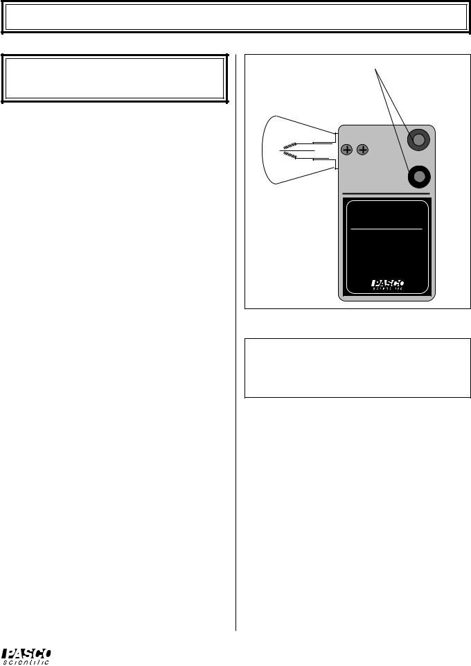
Stefan-Boltzmann Lamp
IMPORTANT: The voltage into the lamp should NEVER exceed 13 V. Higher voltages will burn out the filament.
The TD-8555 Stefan-Boltzmann Lamp (Figure 3) is a high temperature source of thermal radiation. The lamp can be used for high temperature investigations of the Stefan-Boltzmann Law. The high temperature simplifies the analysis because the fourth power of the ambient temperature is negligibly small compared to the fourth power of the high temperature of the lamp filament (see Experiments 3 and 4). When properly oriented, the filament also provides a good approximation to a point source of thermal radiation. It therefore works well for investigations into the inverse square law.
By adjusting the power into the lamp (13 Volts max, 2 A min, 3 A max), filament temperatures up to approximately 3,000 °C can be obtained. The filament temperature is determined by carefully measuring the voltage and current into the lamp. The voltage divided by the current gives the resistance of the filament.
Equipment Recommended
AC/DC LV Power Supply (SF-9584) or equivalent capable of 13 V @ 3 A max
T = |
R - Rref |
+ T |
|
|
aRref |
ref |
|
|
|
||
For small temperature changes, the temperature of the tungsten filament can be calculated using a, the temperature coefficient of resistivity for the filament:
where, |
|
|
T |
= |
Temperature |
R |
= |
Resistance at temperature T |
Tref |
= |
Reference temperature (usually room temp.) |
Rref = Resistance at temperature Tref |
||
a |
= |
Temperature coefficient of resistivity for the |
filament (α = 4.5 x 10⁻³ K-1 for tungsten)
For large temperature differences, however, a is not constant and the above equation is not accurate.
Banana Connectors:
Connect to Power Supply – 13 V MAX, (2 A min, 3 A max)
TD-8555 |
STEFAN-BOLTZMAN |
LAMP |
CAUTION |
13 VDC MAX LAMP VOLTAGE |
FOR MAXIMUM ACCURACY, |
PASCO scientific |
MEASURE VOLTAGE AT |
BINDING POSTS |
USE NO.1196 BULB |
Figure 3 Stefan-Boltzmann Lamp
REPLACEMENT BULB: GE Lamp No. 1196, available at most auto parts stores.
ä NOTE: When replacing the bulb, the leads should be soldered to minimize resistance.
For large temperature differences, therefore, determine the temperature of the tungsten filament as follows:
Accurately measure the resistance (Rref) of the tungsten filament at room temperature (about 300 °K).
Accuracy is important here. A small error in Rref will result in a large error in your result for the fila-
ment temperature.
When the filament is hot, measure the voltage and current into the filament and divide the voltage by the current to measure the resistance (RT).
Divide RT by Rref to obtain the relative resistance (RT/Rref).
Using your measured value for the relative resistivity of the filament at temperature T, use Table 2 on the following page, or the associated graph, to determine the temperature of the filament.
3

Thermal Radiation System |
012-04695D |
Table 2 Temperature and Resistivity for Tungsten
R/R300K |
Temp |
Resistivity |
R/R300K |
Temp |
Resistivity |
R/R300K |
Temp |
Resistivity |
R/R300K |
Temp |
Resistivity |
°K |
µΩ cm |
°K |
µΩ cm |
°K |
µΩ cm |
°K |
µΩ cm |
||||
|
|
|
|
|
|
|
|
|
|
|
|
1.0 |
300 |
5.65 |
5.48 |
1200 |
30.98 |
10.63 |
2100 |
60.06 |
16.29 |
3000 |
92.04 |
1.43 |
400 |
8.06 |
6.03 |
1300 |
34.08 |
11.24 |
2200 |
63.48 |
16.95 |
3100 |
95.76 |
1.87 |
500 |
10.56 |
6.58 |
1400 |
37.19 |
11.84 |
2300 |
66.91 |
17.62 |
3200 |
99.54 |
2.34 |
600 |
13.23 |
7.14 |
1500 |
40.36 |
12.46 |
2400 |
70.39 |
18.28 |
3300 |
103.3 |
2.85 |
700 |
16.09 |
7.71 |
1600 |
43.55 |
13.08 |
2500 |
73.91 |
18.97 |
3400 |
107.2 |
3.36 |
800 |
19.00 |
8.28 |
1700 |
46.78 |
13.72 |
2600 |
77.49 |
19.66 |
3500 |
111.1 |
3.88 |
900 |
21.94 |
8.86 |
1800 |
50.05 |
14.34 |
2700 |
81.04 |
26.35 |
3600 |
115.0 |
4.41 |
1000 |
24.93 |
9.44 |
1900 |
53.35 |
14.99 |
2800 |
84.70 |
|
|
|
4.95 |
1100 |
27.94 |
10.03 |
2000 |
56.67 |
15.63 |
2900 |
88.33 |
|
|
|
|
|
|
|
|
|
|
|
|
|
|
|
Relative
Resistivity
RT
R 300K
Temperature versus Resistivity for Tungsten
20
19
18
17
16
15
14
13
12
11
10
9
8
7
6
5
4
3
2
1
0
0 |
500 |
1000 |
1500 |
2000 |
2500 |
3000 |
3500 |
Temperature (Kelvin)
4
012-04695D |
Thermal Radiation System |
|
|
Experiment 1: Introduction to Thermal Radiation
EQUIPMENT NEEDED: |
|
— Radiation Sensor, Thermal Radiation Cube |
— Window glass |
— Millivoltmeter |
— Ohmmeter. |
ä NOTES:
If lab time is short, it's helpful to preheat the cube at a setting of 5.0 for 20 minutes before the laboratory period begins. (A very quick method is to preheat the cube at full power for 45 minutes, then use a small fan to reduce the temperature quickly as you lower the power input. Just be sure that equilibrium is attained with the fan off.)
Part 1 and 2 of this experiment can be performed simultaneously. Make the measurements in Part 2 while waiting for the Radiation Cube to reach thermal equilibrium at each of the settings in Part 1.
When using the Radiation Sensor, always shield it from the hot object except for the few seconds it takes to actually make the measurement. This prevents heating of the thermopile which will change the reference temperature and alter the reading.
Radiation Rates from Different Surfaces
Part 1
Connect the Ohmmeter and Millivoltmeter as shown in Figure 1.1.
Turn on the Thermal Radiation Cube and set the power switch to “HIGH”. Keep an eye on
the ohmmeter reading. When it gets down to |
|
|
|
|
|
|
|
|
|
|
|
|
about 40 kΩ, reset the power switch to 5.0. (If |
|
|
|
|
|
|
|
|
|
|
|
|
the cube is preheated, just set the switch to 5.0.) |
|
|
|
|
|
|
|
|
|
|
|
|
When the cube reaches thermal equilibrium— |
|
|
|
|
|
|
|
|
|
|
|
|
the ohmmeter reading will fluctuate around a |
|
|
|
|
|
|
|
|
|
|
|
|
relatively fixed value—use the Radiation |
|
|
|
|
|
|
|
|
|
|
|
|
Sensor to measure the radiation emitted from |
|
|
|
|
|
|
|
|
|
|
|
|
each of the four surfaces of the cube. Place |
|
|
|
|
UTIO! |
|
|
MIS |
TO |
R |
54A |
|
|
|
|
|
|
|
|
N TH |
ER |
|
|
|
|
|
|
|
|
|
|
|
|
|
|
|
||
|
CAUTION: HOT! |
|
|
100W |
A |
T |
|
|
|
-85 |
|
|
the Sensor so that the posts on its end are in |
|
|
C HO |
|
|
odelTD |
|
E) |
||||
ON |
4 |
5 |
BULB |
|
|
|
M |
|
|
|
||
MAX. |
|
|
|
(LES |
'SC |
UB |
||||||
|
|
3 |
|
|
|
|
|
|
|
|||
|
|
|
6 |
|
|
|
|
LIE |
|
|
||
contact with the cube surface (this ensures that |
|
2 |
|
7 |
|
|
|
|
|
|
|
|
OFF |
1 |
|
8 |
|
|
|
|
|
|
|
|
|
the distance of the measurement is the same for |
|
LOW |
|
HIGH |
|
|
|
|
|
|
|
|
|
|
|
|
|
|
|
|
|
|
|
Millivoltmeter |
|
all surfaces). Record your measurements in the |
|
|
|
|
|
|
|
|
|
|
|
|
|
|
|
|
|
|
|
|
|
|
|
|
|
appropriate table on the following page. Also |
|
|
|
|
|
|
|
|
|
|
|
|
measure and record the resistance of the ther- |
|
|
|
|
|
|
|
|
|
|
|
|
mistor. Use the table on the base of the cube to |
|
Ohmmeter |
|
|
|
|||||||
determine the corresponding temperature. |
|
|
|
|
||||||||
|
|
|
|
|
|
|
|
|
|
|
|
|
Increase the power switch setting, first to 6.5, then to 8.0, then to “HIGH”. At each
setting, wait for the cube to reach thermal equilibrium, then repeat the measurements of step 1 and record your results in the appropriate table.
5
 Loading...