


Includes
Teacher's Notes
and
Typical
Experiment Results
Instruction Manual and Experiment Guide for the PASCO scientific Model ME-9341
012-03051F 3/95
INTRODUCTORY
ROTATIONAL APPARATUS
|
|
|
|
|
|
|
|
|
|
|
|
|
|
|
|
|
|
|
|
|
|
|
|
|
|
|
|
|
|
|
|
|
|
|
|
|
|
|
|
|
|
|
|
|
|
|
|
|
|
|
|
|
|
|
|
|
|
|
|
|
|
|
|
|
|
|
|
|
|
|
|
|
|
|
|
|
|
|
|
|
|
|
|
|
|
|
|
|
|
|
|
|
|
|
|
|
|
|
|
|
|
|
|
|
|
|
|
|
|
|
|
|
|
|
|
|
|
|
|
|
|
|
|
|
|
|
|
|
|
|
|
|
|
|
|
|
|
|
|
|
|
|
|
|
|
|
|
|
|
|
|
|
|
|
|
|
|
|
|
|
|
|
|
|
|
|
|
|
|
|
|
|
|
|
|
|
|
|
|
|
|
|
|
|
|
|
|
|
|
|
|
|
|
|
|
|
|
|
|
|
|
|
|
|
|
|
|
|
|
|
|
|
|
|
|
|
|
|
|
|
|
|
|
|
|
|
|
|
|
|
|
|
|
|
|
|
|
|
|
|
|
|
|
|
|
|
|
|
|
|
|
|
|
|
|
|
|
|
|
|
|
|
|
|
|
|
|
|
|
|
|
|
|
|
|
|
|
|
|
|
|
|
|
|
|
|
|
|
|
|
|
|
|
|
|
|
|
|
|
|
|
|
|
|
|
|
|
|
|
|
|
|
|
|
|
|
|
|
|
|
|
|
|
|
|
|
|
|
|
|
|
|
|
|
|
|
|
|
|
|
|
|
|
|
|
|
|
|
|
|
|
|
|
|
|
|
|
|
|
|
|
|
|
|
|
|
|
|
|
|
|
|
|
|
|
|
|
|
|
|
|
|
|
|
|
|
|
|
|
|
|
|
|
|
|
|
|
|
|
|
|
|
|
|
|
|
|
|
|
|
|
|
|
|
|
|
|
|
|
|
|
|
|
|
|
|
|
|
|
|
|
|
|
|
|
|
|
|
|
|
|
|
|
|
|
|
|
|
|
|
|
|
|
|
|
|
|
|
|
|
|
|
|
|
|
|
|
|
|
|
|
|
|
|
|
|
|
|
|
|
|
|
|
|
|
|
|
|
|
|
|
|
|
|
|
|
|
|
|
|
|
|
|
|
|
|
|
|
|
|
|
|
|
|
|
|
|
|
|
|
|
|
|
|
|
|
|
|
|
|
|
|
|
|
|
|
|
|
|
|
|
|
|
|
|
|
|
|
|
|
|
|
|
|
|
|
|
|
|
|
|
|
|
|
|
|
|
|
|
|
|
|
|
|
|
|
|
|
|
|
|
|
|
|
|
|
|
|
|
|
|
|
|
|
|
|
|
|
|
|
|
|
|
|
|
|
|
|
|
|
|
|
|
|
|
|
|
|
|
|
|
|
|
|
|
|
|
|
|
|
|
|
|
|
|
|
|
|
|
|
|
|
|
|
|
|
|
|
|
|
|
|
|
|
|
|
|
|
|
|
|
|
|
|
|
|
|
|
|
|
|
|
|
|
|
|
|
|
|
|
|
|
|
|
|
|
|
|
|
|
|
|
|
|
|
|
|
|
|
|
|
|
|
|
|
|
|
|
|
|
|
|
|
|
|
|
|
|
|
|
|
|
|
|
|
|
|
|
|
|
|
|
|
|
|
|
|
|
|
|
|
|
|
|
|
|
|
|
|
|
|
|
|
|
|
|
|
|
|
|
|
|
|
|
|
|
|
|
|
|
|
|
|
|
|
|
|
|
|
|
|
|
|
|
|
|
|
|
|
|
|
|
|
|
|
|
|
|
|
|
|
|
|
|
|
|
|
|
|
|
|
|
|
|
|
|
|
|
|
|
|
|
|
|
|
|
|
|
|
|
|
|
|
|
|
|
|
|
|
© 1987 PASCO scientific |
$5.00 |
||||||||||||||||||||||||||||||||||||||||||||||||||||||

012-03051F |
Introductory Rotational Apparatus |
|
|
Table of Contents
Section ........................................................................................................ |
Page |
Copyright, Warranty and Equipment Return ................................................... |
ii |
Introduction ..................................................................................................... |
1 |
Equipment ........................................................................................................ |
2 |
Setup ............................................................................................................. |
4 |
Timing with a Photogate.................................................................................. |
6 |
Five Copy-Ready Experiments:....................................................................... |
7 |
Experiment 1: Angular Acceleration—1 .................................................. |
9 |
Experiment 2: Angular Acceleration—2 ................................................. |
11 |
Experiment 3: Gravitational - Rotational Energy .................................... |
15 |
Experiment 4: Frictional Torque ............................................................. |
17 |
Experiment 5: Rotational Collisions........................................................ |
19 |
Teacher's Guide .............................................................................................. |
23 |
Appendix ........................................................................................................ |
33 |
Technical Support .................................................................................... |
back cover |
i

Introductory Rotational Apparatus |
012-03051F |
|
|
Copyright, Warranty and Equipment Return
Please— Feel free to duplicate this manual subject to the copyright restrictions below.
Copyright Notice
The PASCO scientific Model ME-9341 Introductory Rotational Apparatus manual is copyrighted and all rights reserved. However, permission is granted to non-profit educational institutions for reproduction of any part of this manual providing the reproductions are used only for their laboratories and are not sold for profit. Reproduction under any other circumstances, without the written consent of PASCO scientific, is prohibited.
Limited Warranty
PASCO scientific warrants this product to be free from defects in materials and workmanship for a period of one year from the date of shipment to the customer. PASCO will repair or replace, at its option, any part of the product which is deemed to be defective in material or workmanship. This warranty does not cover damage to the product caused by abuse or improper use. Determination of whether a product failure is the result of a manufacturing defect or improper use by the customer shall be made solely by PASCO scientific. Responsibility for the return of equipment for warranty repair belongs to the customer. Equipment must be properly packed to prevent damage and shipped postage or freight prepaid. (Damage caused by improper packing of the equipment for return shipment will not be covered by the warranty.) Shipping costs for returning the equipment, after repair, will be paid by PASCO scientific.
Credits
This manual authored by: Ed Pitkin
This manual edited by: Dave Griffith
Teacher’s guide written by: Dave Griffith
Equipment Return
Should the product have to be returned to PASCO scientific for any reason, notify PASCO scientific by letter, phone, or fax BEFORE returning the product.
Upon notification, the return authorization and shipping instructions will be promptly issued.
ä NOTE: NO EQUIPMENT WILL BE ACCEPTED FOR RETURN WITHOUT AN AUTHORIZATION FROM PASCO.
When returning equipment for repair, the units must be packed properly. Carriers will not accept responsibility for damage caused by improper packing. To be certain the unit will not be damaged in shipment, observe the following rules:
The packing carton must be strong enough for the item shipped.
Make certain there are at least two inches of packing material between any point on the apparatus and the inside walls of the carton.
Make certain that the packing material cannot shift in the box or become compressed, allowing the instrument come in contact with the packing carton.
Address: |
PASCO scientific |
|
10101 Foothills Blvd. |
|
Roseville, CA 95747-7100 |
Phone: |
(916) 786-3800 |
FAX: |
(916) 786-3292 |
email: |
techsupp@pasco.com |
web: |
www.pasco.com |
ii
012-03051F |
Introductory Rotational Apparatus |
|
|
Introduction
With the PASCO ME-9341 Introductory Rotational Apparatus, your students can perform a variety of experiments in rotational mechanics, including investigations into torque, angular acceleration, moment of inertia, and conservation of angular momentum.
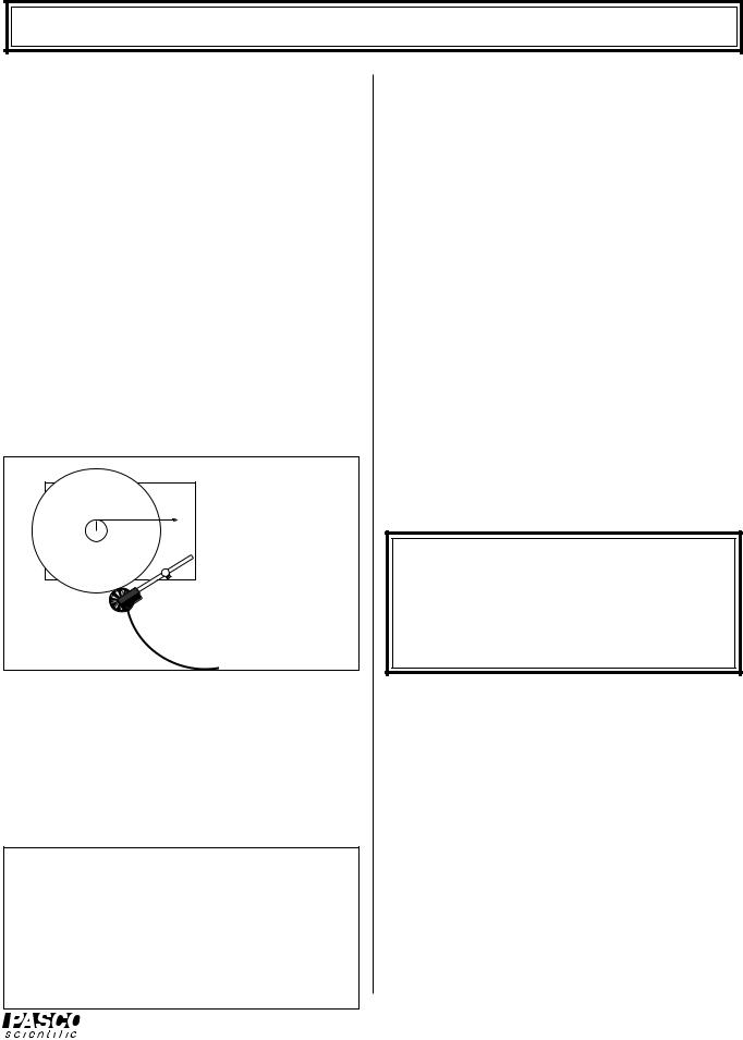
Setup is quick and operation is simple. As shown in Figure 1, a platter spins on low-friction ball bearing supports. Torques can be applied to the platter with various torque arms and forces, and the angular velocity of the platter can be monitored over time to determine angular acceleration. The moment of inertia of the rotating system can be varied by adding a second platter, a steel ring, or a steel block.
The motion of the platter is described mathematically by Newton's Second Law in its rotational form: t = Ia, where t is the applied torque, I is the moment of inertia of the spinning platter, and a is the angular acceleration of the platter.
|
F |
τ = r x F = Ια |
r |
|
|
|
|
 Smart Pulley with photogate (not included)
Figure 1 Rotational Diagram
Timing the Rotational Motion
A variety of timing systems can be used to measure the motion of the Introductory Rotational Apparatus. The most versatile option is the PASCO Smart Pulley.
However, standard photogate timers such as the PASCO model ME-9206A or ME-9215A can also be used.
NOTE: The original 3-hole Smart Pulley has been replaced . The new PASCO Smart Pulley has 10 spokes and less friction than the 3-hole pulley. If you currently have 3-hole pulleys and wish to replace them with 10-spoke pulleys an upgrade kit is available from PASCO. The upgrade kit includes software that allows use of either the 3-hole or 10-spoke pulleys. This manual makes reference to both pulleys.
Timing with the Smart Pulley
The Smart Pulley (see Figure 1) connects to your Apple II computer (II+, IIe, IIc, or IIGS), or IBM PC or compatible, providing automatic data collection, analysis, and graphing. As the platter spins, the pulley is held lightly against the rim of the platter, and therefore spins with the platter. The Smart Pulley photogate monitors the rotation of the pulley, sending its signals to the computer for timing and analysis. The software for the Smart Pulley includes options designed specifically for use with the Introductory Rotational Apparatus, producing tables and graphs showing angular displacement, velocity, and acceleration as a function of time.
The Smart Pulley is more than just a computer timer for the Rotational Apparatus. When used with an Apple II or IBM PC computer and standard laboratory equipment such as an air track or dynamics carts, the Smart Pulley provides a complete introductory lab in linear mechanics. See the PASCO catalog for more information about the Smart Pulley System, or Smart Pulley Timer and Accessories.
IMPORTANT: If you are using the Smart Pulley to time the motion of the Rotational Apparatus, you should begin by familiarizing yourself with the setup and operation of the Smart Pulley. See the Smart Pulley manual and the Smart Pulley Timer Software Manual.
Timing with a Standard Photogate
Timing for the Rotational Apparatus can also be performed using a standard photogate timer, such as PASCO model ME-9206A or ME-9215A. The five ready-to-use experiments in this manual assume you are using the Smart Pulley to time your experiments with the Rotational Apparatus. However, each of these experiments can be modified for standard photogate timing. See the section, "Timing with a Photogate." For more information about photogate timers, see the current PASCO catalog.
1

Introductory Rotational Apparatus |
012-03051F |
|
|
Equipment
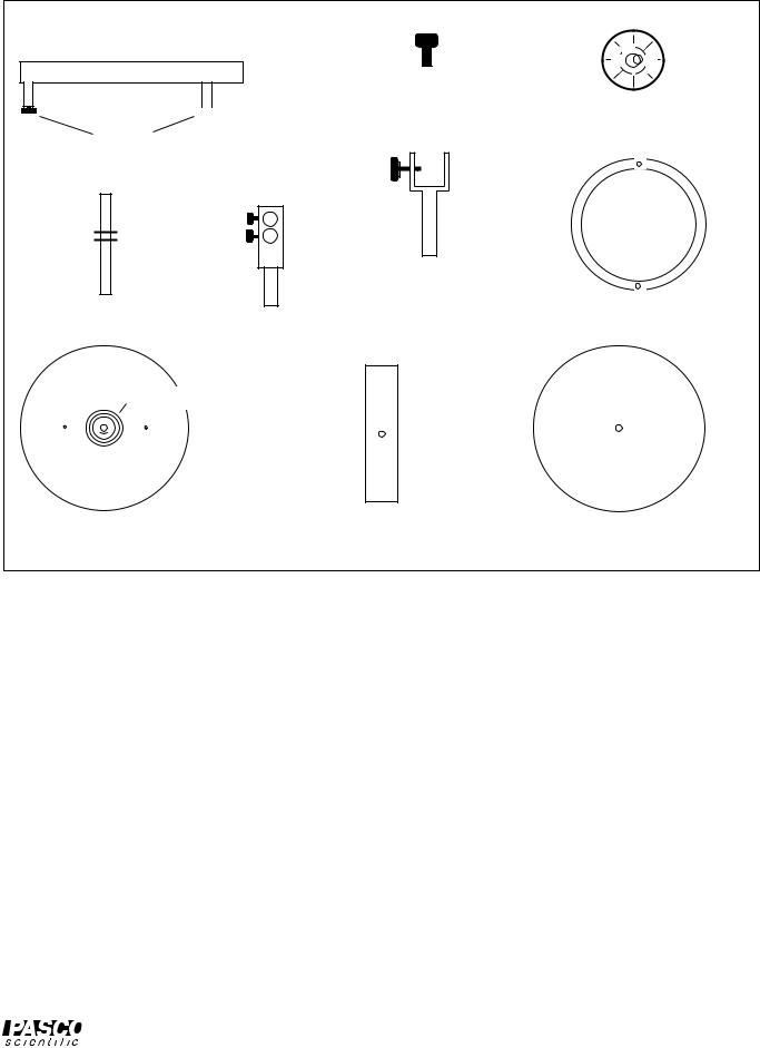
The following equipment is included with the ME-9341 Introductory Rotational Apparatus (see Figure 2):
–Base with leveling supports and main bearing
–Spindle
–Main platter with step pulley
–Pulley clamp
–Tensioning screw
–Level
–Photogate clamp
–Steel bar
–Auxiliary platter
–Steel ring
–Instruction manual and experiments guide
You will also need either:
A PASCO Smart Pulley System (Model ME-9420 or ME-9421) or one of the Smart Pulley Timers (ME9382, ME-9384, ME-9386, or ME-9388) - (Please see the PASCO catalog for complete details.) - and an Apple II or IBM PC (or compatible) computer.
or
A photogate timing system such as PASCO Model ME-9206A or ME-9215A.
Measuring Equipment Parameters
In experiments with the Rotational Apparatus, you will often be comparing experimentally determined values, such as moment of inertia or angular acceleration, with calculated values based on theory. These listed, precalculated values may be helpful in those calculations. For best results, however, we recommend that you make the necessary measurements yourself. The following suggestions may be helpful in making certain measurements accurately:
To measure the radii of the step pulley, use calipers to determine the diameter, then divide by two.
To measure the radius of the Smart Pulley groove, observe the LED on the top of the photogate as you pull a string over the pulley. Measure the distance, L, through which you pull the string for a predetermined number, n, of LED flashes. The radius of the pulley groove is then r = 3L/2 n for a 3-hole pulley or r = 10L/2 n for a 10-spoke pulley.
To measure the radius of the Smart Pulley outer circumference, roll the Smart Pulley over a smooth, flat surface. Measure the distance, L, over which you pull the pulley for a predetermined number, n, of LED flashes. Again, the radius of the outer circumference of the pulley is r = 3L/2 n for a 3-hole pulley or r = 10L/2 n for a 10-spoke pulley. (You can draw a mark on the edge of the rim of the Smart Pulley to use as a reference mark for measuring L.)
NOTE: If you would rather not make the measurements yourself, use the values in the box below. They should be valid to within 10 percent for your Rotational Apparatus.
Main platter: Mass = 991 gm; Radius = 12.7 cm; Moment of inertia = 7.50 x 10⁻³ kgm2
Step pulley: Radii = (1.50 cm, 2.00 cm, 2.50 cm)
Auxiliary platter: Mass = 894 gm; Radius = 12.7 cm; Moment of inertia = 7.22 x 10⁻³ kgm2
Steel bar: Mass = 690 gm; Dimensions = 22.2 x 5.1 cm; Moment of inertia = 2.98 x 10⁻³ kgm2
Steel ring: Mass = 701 gm; Outer radius = 6.4 cm; Inner radius = 5.4 cm;
Moment of inertia =2.46 x 10⁻³ kgm2
Smart Pulley: |
|
3-hole |
|
10-spoke |
|
|
|||
|
|
|
|
|
radius inside groove |
|
2.29 cm |
|
2.38 cm |
|
|
|
|
|
radius outside circum. |
|
2.51 cm |
|
2.54 cm |
moment of inertia |
|
15.3x10⁻⁷kgm2 |
|
18.6x10⁻⁷kgm2 |
Note: Platters of the earlier versions of the ME9341 were made from masonite. Their mass and moment of inertia are given below.
Main platter: Mass = 776 gm; Radius = 12.7 cm; Moment of inertia = 6.01 x 10⁻³ kgm2
Auxiliary platter: Mass = 694 gm; Radius = 12.7 cm; Moment of inertia = 5.82 x 10⁻³ kgm2
2
012-03051F |
|
Introductory Rotational Apparatus |
|
|
|
|
|
|
|
|
|
 Bearing
Base Tensioning
screws (2)


 Bubble level Leveling
supports
Steel ring
Photogate
clamp
Spindle
Pulley clamp
Step pulley
Main platter |
Steel bar |
Auxiliary platter |
Figure 2 Rotational Apparatus Equipment
3

Introductory Rotational Apparatus |
012-03051F |
|
|
Setup
Place the base on a flat table. Place the bubble level on top of the base, then adjust the leveling supports until the top of the base is level.
NOTE: Leveling the base is important. Not only does it ensure the accuracy of your experimental results, it also prevents uneven wear on the bearings.
Slide the spindle into the bushing of the bearing assembly. Either end of the spindle can face up, but you will want the long end facing up if you plan on using the auxiliary platter, the ring, or the bar.
Place the Main Platter over the spindle. The step pulley can face up or down, but should face down if you plan on using the auxiliary platter, the ring, or the bar.
If you are using a standard photogate timer:
See the "Timing with a Photogate" section.
If you are using the Smart Pulley:
Slide the stem of the Smart Pulley clamp into either of the two bushings near the edge of the base.
Place the Smart Pulley rod through the hole in the Smart Pulley clamp, level the pulley, and tighten the screw. (Use the upper hole in the clamp if the Step pulley is facing down, the lower hole if the step pulley is facing up.)
If you wish, attach a rubber band (not included) over the rod of the Smart Pulley and a leg under the base, as shown in Figure 3. This can be useful in collision experiments, in which an extra "hand" may be needed to keep the Smart Pulley in contact with the platter.
See the Smart Pulley System manual for connecting and using the Smart Pulley. For most experiments using the rotational apparatus, you will want to use Option M – MOTION TIMER from the Smart Pulley main menu. When you are ready to begin timing, just press the Smart Pulley lightly against the edge of the platter.
If you are applying torque with a hanging mass:
Attach a piece of thread to the step pulley using the screw to hold the thread, or tying it to the hole in the smallest pulley (see Figure 4).
Thread the thread through the holes in the step pulley to the desired level. (For instance, thread it through one hole if you are using the smallest pulley, two holes if you are using the medium size pulley, etc.)
|
Smart Pulley |
Smart Pulley clamp |
|
Spindle |
|
||
|
Rubber band |
||
Main platter |
|
||
|
|
||
|
|
Pulley |
|
|
|
Universal |
|
|
|
Clamp |
|
|
|
Hanging |
|
(SIDE VIEW) |
|
Mass |
|
|
Main platter |
||
|
|
Universal |
|
Spindle |
Clamp |
||
|
|||
Tensioning Screws |
Hanging |
||
Mass |
|||
|
|
||
|
|
Pulley |
|
|
|
Rubber band |
|
|
|
Smart Pulley clamp |
|
(TOP VIEW) |
Smart Pulley |
||
Figure 3 Setting Up the Rotational Apparatus
Thread parallel to platter.
Figure 4 Threading the Step Pulley
4

012-03051F |
Introductory Rotational Apparatus |
|
|
11Attach a pulley to the base of the apparatus using the Smart Pulley table clamp as shown in Figure 3. If you don't have the table clamp, a pulley mounted to a ring stand can be used, as long as the height and angle of the pulley are adjustable.
12Pass the thread over the pulley and adjust the pulley angle and height so the thread is parallel with the platter surface and with the groove in the pulley.
NOTE: When using a falling mass to accelerate the platter, there are two setup options.
Option a—This option requires the Smart Pulley and a second pulley, set up as shown in Figure 3. This method is slightly less accurate than option b, but conceptually simpler. When entering the graphing mode of the Smart Pulley software, you will be asked to identify the type of device being used to interrupt the photogate. If you are using the version of Smart Pulley Timer software that functions with either 10-spoke or 3-hole pulleys, simply choose ROTATIONAL APPARATUS. If you are using an older version of Smart Pulley Timer and a 3-hole pulley, choose ROTATIONAL APPARATUS. However, if you are using an
older version of Smart Pulley Timer software and a 10-spoke pulley, choose OTHER (ANGULAR MEASUREMENT). The computer will ask you to enter the angle in radians between the spokes. Enter 0.125 [calculated by using θ = 2π/10
(RSMART PULLEY/RMAIN PLATTER)]. The computer
will then automatically convert the measured times to determine the angular displacement, velocity, and acceleration of the platter. The slight decrease in accuracy results from the friction caused by the pressure of the Smart Pulley on the rim of the spinning platter.
Option b—In this option, use the Smart Pulley as the pulley that supports the hanging weight. No other pulley is needed. When asked by the computer to identify the type of device being used to interrupt the photogate, select option F—
OTHER (ANGULAR MEASUREMENT). You will then be asked to enter the angle between openings. Enter one of the values shown below, depending on which tier of the step pulley you are using and the type of Smart Pulley you have (these values are the angle, in radians, through which the platter turns for each signal sent to the computer by the Smart Pulley).
Tier of step pulley used |
|
3-hole |
|
10-spoke |
|
|
|
|
|
Smallest |
|
3.20 |
|
1.00 |
Middle |
|
2.49 |
|
0.75 |
Largest |
|
1.92 |
|
0.60 |
|
|
|
|
|
These values can be calculated using the formula:
θ = 2 |
/3 (R p/Rsp) |
for a 3-hole pulley |
or θ = 2 |
/10 (R p/Rsp) |
for a 10-spoke pulley |
where Rp is the radius of the Smart Pulley groove, and Rsp is the radius of the tier of the step pulley that is being used.
5
Introductory Rotational Apparatus |
012-03051F |
|
|
Timing with a Photogate
If you don't have the Smart Pulley system, a PASCO photogate can be used to time the Rotational Apparatus. Other photogates can be used as well. The Rotational Apparatus includes a mounting clamp that should work with most photogates.
To Use a Photogate:
Mount the photogate in the photogate clamp, and mount the photogate clamp in the pulley clamp, as shown in Figure 5.
Tape a piece of cardboard to the top of the platter to trigger the photogate. The shape of the cardboard depends on which of the following timing techniques you choose.
PASCO photogates have three timing modes: Pulse, Gate, and Pendulum. If your photogate has these timing modes, any of the following four timing techniques can be used:
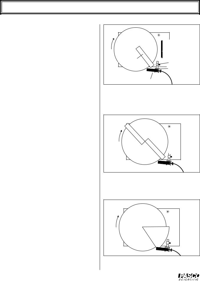
1.PULSE MODE (Method 1)— In pulse mode, the photogate will be triggered each time the leading edge of the cardboard interrupts the photogate beam (see Figure 5). The times displayed will therefore show the time for one full revolution of the platter. Experimenters will then have one revolution to record the time before a new time is displayed. (Just divide 2 by the measured time to determine the angular velocity of the platter in radians/second.)
2.PULSE MODE (Method 2)— Tape two pieces of cardboard to the main platter (see Figure 6). If the cardboard pieces are accurately placed so the leading edges are along a single diameter of the platter, the timing resolution is twice as good as with a single cardboard piece. The displayed times will show the time per 1/2 revolution of the platter.
3.GATE MODE— Tape a one radian sector of cardboard to the top of the main platter (see Figure 7). In gate mode, for each revolution of the platter, the timer will display the time during which the cardboard interrupted the photogate. The reciprocal of the measured times will therefore give the angular velocity in radians/second. (See the Appendix for a one radian sector that you can copy and use as a template for cutting the cardboard.)
6
Cardboard
Pulley clamp
Photogate clamp
Photogate
Figure 5 Pulse Mode (Method 1) and Pendulum
Mode
Figure 6 Pulse Mode (Method 2)
One Radian |
Sector |
Figure 7 Gate Mode
012-03051F |
Introductory Rotational Apparatus |
|
|
4.PENDULUM MODE— If the rotational speed is too great to record the times as they are displayed, use a single cardboard piece, as in Figure 5, and set the photogate to pendulum mode. The timer will display the time for two full revolutions of the platter, allowing one revolution time for reading and recording the value.
5.Alternative Methods
•Use the PASCO Model AI-6577A Apple Compatible Photogate System. This system offers many of the same advantages as Smart Pulley timing. However, since it was not designed specifically for the Rotational Apparatus, experiments will have to be adapted somewhat.
Five Copy-Ready Experiments
The following five experiments are written in worksheet form.
Feel free to photocopy them for use in your lab.
Some precautions will help keep your data as accurate as
possible:
Before conducting any experiment, always level the base as accurately as possible.
When using a thread to apply a torque to the platter, keep the thread as parallel to the platter as possible.
When measuring the radius of a tier of the step pulley, use calipers to measure the diameter, then divide by two.
NOTE: For more information about each of these labs, including relevant equations and suggested alternatives, see the LAB NOTES section, near the end of this manual.
7

Introductory Rotational Apparatus |
012-03051F |
|
|
Notes:
8
 Loading...