


 Loading...
Instruction Manual
012-13762D
Materials Testing Machine
ME-8236
Part of the
Comprehensive
Materials Testing System
ME-8244
WARNING: Provide proper eye protection when using the Materials Testing Machine or its Accessories. Operate the Materials Testing Machine behind protective Safety Shields.
USB Link*
*Items from the  ME-8230 Materials
Testing System
Tensile Samples*
(60)
Velcro® Hook
Material
Safety Shield (2)
Crankshaft
Sensor
Cable
Leadscrews
Velcro® Loop 
Material
 Load Bar
(crosshead)
7100 N
Load Cell
Base
|
|
Materials Testing |
Load Bar |
Calibration |
Machine |
Rod and Nut |
|
|
Round Nut |
|
|
|
|

Materials Testing Machine |
Introduction |
|
|
|
|
Materials Testing Machine (ME-8236)
.
Included Items |
Included Items |
|
|
Materials Testing Machine |
Calibration Rod and Nut |
|
|
Load Bar Round Nut |
Safety Shield (2) |
|
|
Required Items*
PASCO Interface (PASPORT compatible)
PASCO Capstone Data Collection Software
*See the PASCO catalog or web site at WWW.PASCO.COM
Materials Testing System (ME-8230)
The Materials Testing System includes the items in the Materials Testing Machine PLUS an interface, software, and sixty tensile samples as shown in Table 1.
Table 1: .Materials Testing System
Model |
Materials Testing System Items |
|
|
ME-8236 |
Materials Testing Machine |
|
|
PS-2100A |
USB Link |
|
|
UI-5401 |
PASCO Capstone Software |
|
|
ME-8231 |
Tensile Sample, Aluminum (10) |
|
|
ME-8232 |
Tensile Sample, Brass (10) |
|
|
ME-8233 |
Tensile Sample, Annealed Steel (10) |
|
|
ME-8234 |
Tensile Sample, Acrylic (10) |
|
|
ME-8235 |
Tensile Sample, Polyethylene (10) |
|
|
ME-8243 |
Tensile Sample, Steel (10) |
|
|
Comprehensive Materials Testing System (ME-8244)
The Comprehensive Materials Testing System includes all the items in the Materials Testing System shown in Table 1 PLUS the accessories and other items shown in Table 2.
Table 2: Comprehensive Materials Testing System
Model |
Comprehensive Materials Testing |
|
System Items |
|
|
ME-8230 |
Materials Testing System (MTS) |
|
|
ME-8229 |
Materials Testing System Base |
|
|
ME-8237 |
Materials Bending Accessory |
|
|
ME-8238 |
Materials Coupon Adapter |
|
|
ME-8239 |
Materials Shear Accessory |
|
|
ME-8240 |
Materials Shear Samples (3 ea. of 3) |
|
|
ME-8241 |
Materials Photoelasticity Accessory |
|
|
ME-8242 |
Materials Structures Beam Adapter |
|
|
ME-8245 |
Material Testing System Clevis Clip |
|
|
ME-8246 |
MTS 10-32 Adapter |
|
|
ME-8247 |
MTS Compression Accessory |
|
|
ME-8248 |
MTS Compression Samples (20) |
|
|
ME-8249 |
MTS Four-point Load Anvil |
|
|
ME-6983 |
Cast Beam Spares Kit (10 molds) |
|
|
ME-7011 |
Photoelastic I-Beams (24 each size) |
|
|
ME-7012 |
Thin I-Beams (24 each size) |
|
|
AP-8222* |
Coupons, Plastic (10 each of 4 types) |
|
|
AP-8223* |
Coupons, Metal (10 each of 5 types) |
|
|
*AP-8217A Replacement Test Coupons (Full Set) consists of the AP-8222 Plastic Coupons and the AP-8223 Metal Coupons.
Introduction
The PASCO Materials Testing Machine is a device for measuring force and displacement for various materials as the materials are stretched, compressed, sheared, or bent. The Materials Testing Machine has a built-in load cell (strain gauge transducer) capable of measuring up to 7100 newtons
(N) of force (1600 pounds), and an optical encoder module that measures displacement of the load bar. A crank-and-gear system raises or lowers the load bar on two leadscrews (also known as power screws or translation screws). Force data from the load cell and displacement data from the encoder module can be recorded, displayed, and analyzed by a PASCO Interface with PASCO Data Collection Software. The sensor cable from the Materials Testing Machine connects to a PASPORT input port. (See the PASCO catalog or web site at www.pasco.com for more information about PASCO interfaces and data collection software.)
2 |
012-13762D |
Model No.ME-8236 |
Materials Testing System |
Included Equipment
The Materials Testing Machine (ME-8236) includes a calibration rod and nut, a load bar round nut, and a pair of safety shields with Velcro® hook material.
Calibration Rod and Nut, Load Bar Round Nut, Safety Shields
•The calibration rod and nut can be used to determine how much the Machine itself flexes as force is applied, either in tension or in compression.
•The load bar round nut is used to connect one end of a tensile sample to the load bar, for example, or can be used to attach an accessory or adapter to the bottom side of the load bar.
•The safety shields attach to the Velcro® loop material on the front and back of the load bar.
Materials Testing System
The Materials Testing System (ME-8230) consists of the Materials Testing Machine, plus a PASPORT interface called the USB Link, PASCO Capstone Software, and sixty tensile samples.
The USB Link connects the sensor cable of the Materials Testing Machine to a USB port on a computer. The PASCO Capstone software records, displays, and analyzes the data from the Materials Testing Machine. (The software is available as an automatic digital download from PASCO.)
The tensile samples include four metals: aluminum, brass, annealed steel, and steel and two plastics: acrylic and polyethylene, for tensile strength testing. There are ten samples for each material.
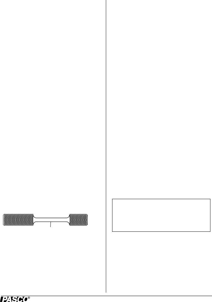
Tensile Sample Information
All the tensile samples (ME-8231 through ME-8235 and ME-8243) have an overall length of 90 millimeters (mm) or 3.5 inches. The center section of each sample has an approximate diameter of 3.3 mm or 0.131 inches. The threaded ends are metric M12 x 1.75.
|
|
31.7 mm |
|
|
|
|
|
|
|
|
|
|
diameter = 3.3 mm |
|
19 mm |
|
|
|
|
||
|
|
|
|
|
|
|
|
|||
|
|
|
|
|
|
|
||||
|
|
|
|
|
|
|
|
|
|
|
|
|
|
|
|
M12 x |
|
1.75 |
|||
|
|
|
||||||||
|
|
|
|
|
|
|
|
|
|
|
The tensile samples can be ordered separately.
The table shows typical values.
Table 3: Typical Values
Material |
Tensile |
Young’s |
|
Strength |
Modulus |
|
|
|
Aluminum (2024-T3) |
400 MPa |
70 GPa |
|
|
|
Brass (360) |
500 MPa |
80 GPa |
|
|
|
Steel (1018) |
700 MPa |
200 GPa |
|
|
|
Annealed Steel (1018) |
400 MPa |
200 GPa |
|
|
|
Polyethylene |
30 MPa |
1 GPa |
|
|
|
Acrylic |
80 MPa |
3 GPa |
|
|
|
Accessories
Table 2 lists accessories and adapters that are included in the Comprehensive Materials Testing System and are available separately for the Material Testing Machine.
Other accessories and adapters are being developed.
Replacement Items
Also available separately are replacement items such as the previously mentioned Tensile Samples, the Materials Shear Samples (ME-8240) with nine metal rods (three each of aluminum, brass, and steel), the Plastic Coupons (AP-8222) with ten samples each of four different plastics, the Metal Coupons (AP-8223) with ten samples each of five different metals, and the MTS Compression Samples (ME-8248).
About This Manual
The manual describes the basic setup of the Materials Testing Machine and the accessories and replacement items included in the Comprehensive Materials Testing System. It also describes the procedure for calibrating the Materials Testing Machine using the included calibration rod and nut.
Experiment Guide
NOTE: An Experiment Guide in electronic format is available to download from www.pasco.com.
Enter “Materials Testing System” in the Search window and look for the downloadable file(s) under “Resources”.
Operation
Caution: Be sure to wear adequate eye protection when using the Materials Testing Machine or its accessories. Operate the Machine from behind a protective shield.
Basic operation involves mounting the Materials Testing Machine firmly to a sturdy support, calibrating the Machine, mounting the item to be tested onto the Materials Testing Machine, connecting the Materials Testing Machine to an
012-13762D |
3 |
Materials Testing Machine |
Operation |
|
|
|
|
interface for data recording, and then turning the crank to apply tension (stretching), compression (squeezing), bending, or shearing (cutting) forces to the test item.
ME-8229 MTS Storage Base
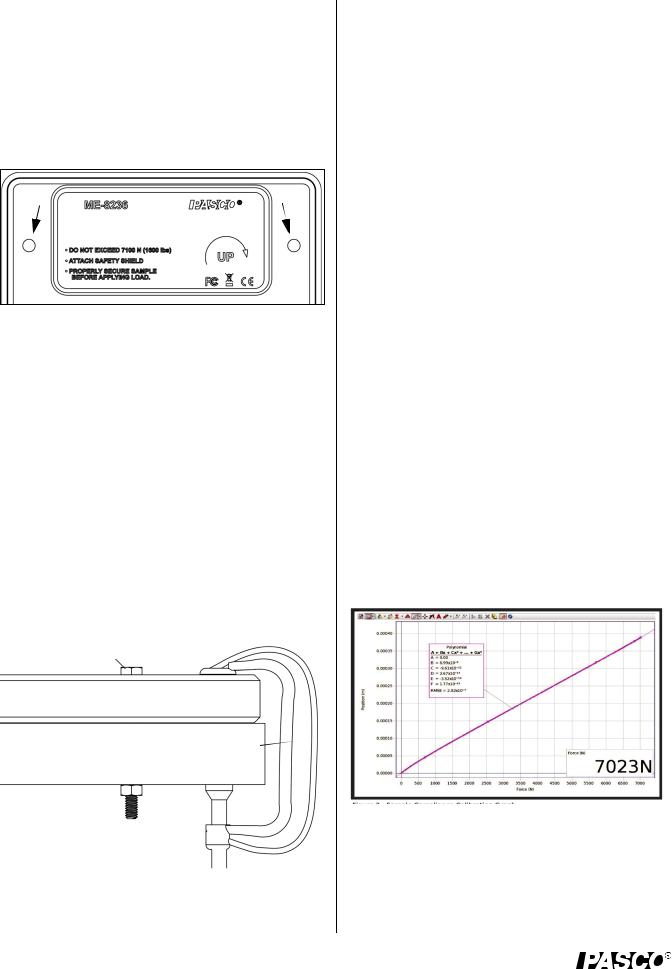
Secure the Materials Testing Machine
There are two holes through the base of the Materials Testing Machine that can be used for bolting the Machine to a sturdy support. The two 6 millimeter (mm) diameter holes are 15 centimeters apart; one on either side of the label.
Bolting the Machine will avoid the problem of the Machine moving during a sample test. The Materials Testing System Storage Base (ME-8229) is designed for two purposes: provide a sturdy base to which the Materials Testing Machine can be bolted, and serve as a storage place for accessories, tools, and other items in the Comprehensive Materials Testing System.
The Storage Base includes two screws and two washers and has two threaded holes that match the spacing of the holes in the Materials Testing Machine base. Place the Materials Testing Machine on the Storage Base. Put the washers on the screws, and put one screw through a hole in the base of the Materials Testing Machine. Align the screw with the threaded hole in the Storage Base, and tighten the screw using your fingers. Put the other screw through the base and align it with the other threaded hole. Use a 7/16 inch (11 mm) wrench to tighten the screws in place. Use C-clamps to fasten the Storage Base to a sturdy table or bench. An option is to bolt the Machine directly to a table or bench as shown. The Storage Base has through holes at each of its corners.
Bolt*
Storage Base
Sturdy support* |
C-clamp* |
Nut* 

(*Items not included)
Calibration Setup
The calibration rod and nut can be used for calibrating the Materials Testing Machine for compression or tension. The
PASCO Capstone data collection software includes a “calibration wizard” that allows the calibration information - called a “compliance calibration” - for the Materials Testing Machine to be stored for later use. (PASCO Capstone is provided in the ME-8230 Materials Testing System.)
Lab 02: Compliance Calibration Tutorial
NOTE: A PASCO Capstone workbook file about compliance calibration is available to download from the PASCO web site. Go to www.pasco.com and enter “Materials Testing System” in the Search window. In the web page that opens, select Materials Testing System. Click “Sample Labs” and then download the ZIP file for Lab 02.
Information covered in the Compliance Calibration Tutorial includes:
•How a compliance calibration works.
•How to create, save, and delete calibrations.
•Hints and practice in making an accurate calibration.
Reason for Calibration
The reason for the compliance calibration procedure is this: if the Materials Testing Machine were perfectly rigid it would give completely accurate measurements of force and displacement. However, the Machine is not perfectly rigid. To correct for the fact that the Machine “flexes” slightly, the stiffness of the Machine is characterized and a calculation is performed in the software to adjust the raw position data and compute the displacement that is due only to the distortion of the sample being tested. The compliance calibration information for the Machine can then be stored within the Machine or stored in a Capstone file.
The calibration rod will not change shape significantly under tension or compression. This means that any displacement measured when the calibration rod is used is due to the flexing of the Materials Testing Machine itself.
For example, the sample graph shows that the Machine flexes 0.2 mm per 3,500 newtons of force when the calibration rod is stretched. If you use the Machine to stretch a material sample, then the “flex” amount of 0.2 mm per 3,500 N would need to be subtracted.
4 |
012-13762D |
Model No.ME-8236 |
Operation |
Creating the Compliance Calibration Information
In the software, a polynomial curve fit is applied to the plot of position versus force data. The coefficients of the polynomial curve fit are saved as the calibration information.
Once the compliance calibration is created for the Machine, the software automatically subtracts the amount of “flex” from the raw data. After the calibration information is stored in the Machine, it cannot be edited. However, it you make a new calibration, it will replace the stored calibration data.
Saving the Calibration Information
The calibration information can be saved in two ways: in the Capstone file or in the Materials Testing Machine itself. If the calibration information is saved in the Capstone file, it can be used with any Materials Testing Machine. If the calibration information is stored in the Materials Testing Machine, the information stays with that unit (even when it is unplugged) and can be used with any Capstone file in the future.
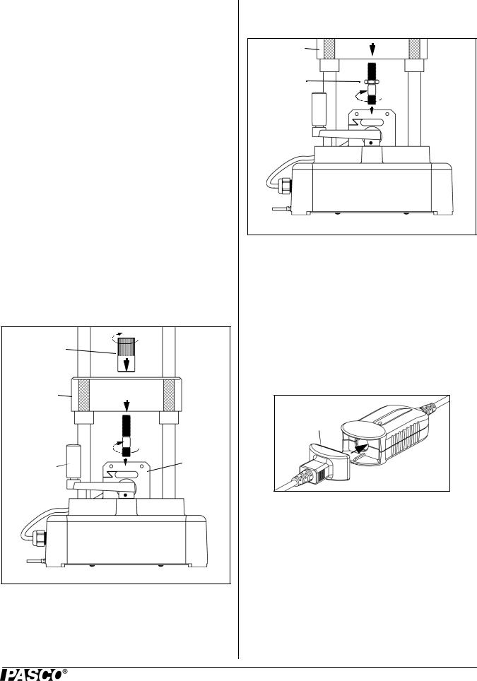
Mount the Calibration Rod for Tension
To mount the calibration rod for tension, screw the short-threaded end of the rod into the top of the load cell.
Lower the load bar until the threaded part at the top of the calibration rod goes through the hole in the load bar. Screw the load bar round nut onto the top of the calibration rod.
Load Bar
Round
Nut
Load Bar (crosshead)
Calibration
Rod
Crank |
Load |
|
Cell |
||
Handle |
||
|
Figure: Mount Calibration Rod for Tension
Mount the Calibration Rod for Compression
To mount the calibration rod for compression, screw the short-threaded end of the rod into the top of the load cell. Screw the calibration nut onto the top threaded part of the calibration rod until the nut is at the bottom of the threaded
section. Lower the load bar until the bottom of the load bar rests on the top of the calibration nut.
Load Bar (crosshead)
Calibration
Nut
Load
 Cell
Cell
Figure: Mount Calibration Rod and Nut for Compression
Attach the Safety Shields
Attach the Velcro® hook material on the two safety shields to the Velcro® loop material on the front and back of the Load Bar. Adjust the position of the shields so that they will block any fragments that may come from the calibration rod in case it accidentally breaks.
Prepare to Record Calibration Data
Connect the plug on the sensor cable into a PASPORT interface, such as the USB Link (included in the Materials Testing System). Connect the interface to a USB port on a computer.
Sensor
Cable Plug
USB Link
See Appendix A for details of the Calibration Procedure.
After the Calibration Procedure is complete, return to this point.
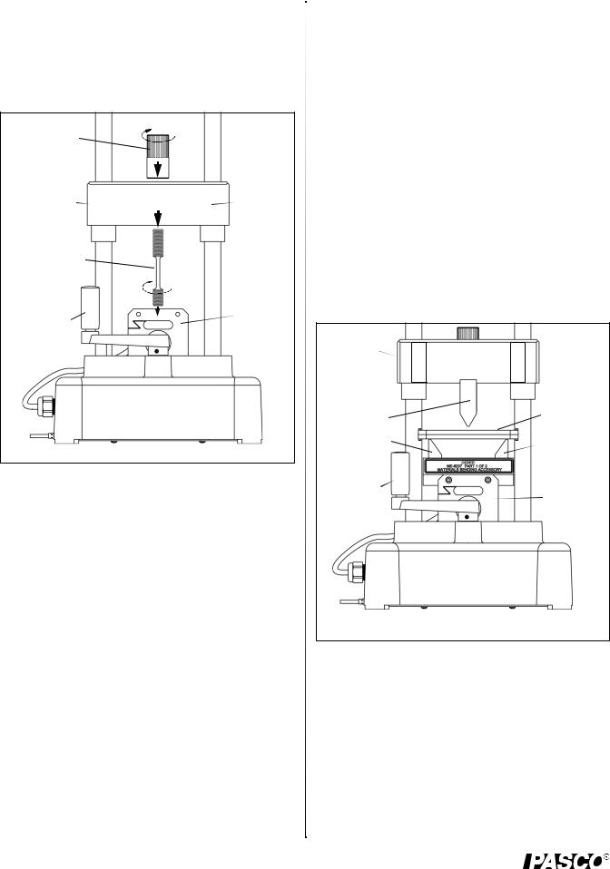
Mount a Tensile Sample
Select a tensile sample to mount onto the Materials Testing Machine. Put the end of the sample with the short threaded section into the threaded hole in the top of the load cell.
Screw in the sample until the top edge of the short threaded section is flush with the top of the load cell.
012-13762D |
5 |
Materials Testing Machine |
Operation |
|
|
|
|
Lower the load bar so that the longer threaded section of the sample goes up through the hole in the center of the load bar. Adjust the load bar until the bottom edge of the longer threaded section is flush with the bottom of the load bar. While holding the tensile sample so it does not turn, screw the sample nut onto the longer threaded section until the sample is held tightly in place.
Load Bar
Sample
Nut
Load Bar |
|
|
|
Loop |
|
|
|
Material |
|
(crosshead) |
|
|
|
|
|
|
|
for Safety |
|
|
|
|
|
|
|
|
|
|
Shield |
Tensile |
|
|||
|
|
|||
Sample |
|
|
||
Crank |
|
Load |
||
|
Cell |
|||
Handle |
|
|||
|
|
|||
Figure: Mount Tensile Sample
Attach the Safety Shields
Attach the Velcro® hook material on the two safety shields to the Velcro® loop material on the front and back of the Load Bar. Adjust the position of the shields so that they will block any fragments that may come from the sample.
Record Data
Prepare PASCO Capstone software to record data. (If there is a stored calibration file that is to be used, select it in the “Calibration” window.)
Start data recording. Turn the crank in a clockwise direction to apply a tension force to the tensile sample. Observe the graph display of force and position. (Note that the default for the Materials Testing Machine in the software shows force and position as ‘negative’ when a tension force is applied. See Appendix A for information about changing signs.))
When the sample breaks, or is stretched the maximum amount, stop data recording.
Materials Bending Accessory (ME-8237)
The Materials Bending Accessory includes a plunger, a adjustable support anvils, and a small hex key (allen wrench). The plunger is mounted on the bottom of the load
bar using the sample nut. The base for the adjustable anvils is screwed onto the top of the load cell.
The spacing between the two triangular support anvils can be adjusted. Use the hex key to loosen the screws holding the anvils and slide them closer together or farther apart. Tighten the screws securely.
Use the sample nut to secure the plunger in place on the load bar. Remove the screws from the base for the anvils and align the base on top of the load cell. Use the screws and the hex key to fasten the base in place.
Place a sample for testing on the two support anvils.
Attach the Safety Shields
Attach the Velcro® hook material on the two safety shields to the Velcro® loop material on the front and back of the Load Bar and adjust the position of the shields if needed.
Apply a Force
Turn the crank counterclockwise to apply a compression force through the plunger onto the sample.
 Sample Load Bar Nut
(crosshead)
Plunger |
Sample |
|
|
||
Anvil |
Anvil |
|
|
Base |
|
Crank |
Load |
|
Handle |
||
Cell |
||
|
Figure: Materials Bending Accessory
Materials Coupon Adapter (ME-8238)
The Materials Coupon Adapter includes two coupon clamps, a “tee-handle”, and a 3/8” socket (12 point). One clamp fits in the load cell and the other fits in the load bar. They can be used to mount a plastic coupon (AP-8222) or metal coupon (AP-8223) onto the Materials Testing Machine for testing of tensile strength.
6 |
012-13762D |
Loading...