


 Loading...
Compumotor
ZETA6104 Indexer/Drive
Installation Guide
|
Rx |
|
|
Rx+ |
6104 |
||||
|
Tx |
|
|
||||||
1COM |
GND |
|
|
|
|
DRIVE |
|||
|
- |
INDEXER |
|
||||||
GND |
|
|
|||||||
|
SHLD |
Rx |
|
||||||
|
- |
|
|
|
|
||||
|
+5V |
|
Tx+ |
|
|
|
|
||
|
Rx |
|
|
Tx |
|
|
|
|
|
2COM |
|
|
GND |
|
|
|
|
||
Tx |
|
|
|
|
|
ZETA |
|||
SHLD |
|
|
|
|
|
||||
|
SHLD |
|
|
|
|
|
|||
|
GND |
|
|
|
|
|
|
||
|
Z- |
|
|
|
|
POWER |
|
||
|
Z+ |
|
|
|
|
||||
ENCODER |
B |
- |
|
|
|
STEP |
TEMP |
||
|
|
|
|
INTERLOCK |
|||||
|
B+ |
|
|
|
OVER |
FAULT |
|||
|
A- |
|
|
|
|
|
|||
|
A+ |
|
|
|
MOTOR |
|
|||
|
+5V |
|
|
|
|
|
TAP |
||
|
GND |
|
|
|
CENTER |
MOTOR |
|||
|
HOM |
|
|
A |
|||||
LIMITS |
|
|
|
|
|||||
TRG- |
|
|
EARTH |
||||||
|
NEG |
|
|
A+ |
|
|
|||
|
POS |
-A |
|
|
|
||||
|
TRG-B |
|
A |
- |
|
|
|||
|
|
|
|
A |
|
|
|
|
|
|
OUT |
|
|
B+ |
|
|
|||
|
GND |
|
|
|
|
||||
|
P |
-CUT |
|
B- |
|
TAP |
|||
|
+5V |
P |
|
|
CENTER |
|
|||
I/O |
IN |
|
|
|
|
INTERLOCK |
|||
|
OUT |
|
|
B |
|
|
|
||
|
|
- |
P |
P |
|
|
|
|
|
|
AUX |
|
|
|
|
|
|
||
|
V |
_I/O |
|
|
|
|
|
||
|
|
|
|
|
|
|
|
|
|
|
|
|
Compumotor |
I/OPROGRAMMABLE |
Hz50/60 |
VAC132-95 |
POWERAC |
Compumotor Division Parker Hannifin Corporation p/n 88-014782-02B

User Information
! WARNING !
6000 Series products are used to control electrical and mechanical components of motion control systems. You should test your motion system for safety under all potential conditions. Failure to do so can result in damage to equipment and/or serious injury to personnel.
6000 Series products and the information in this user guide are the proprietary property of Parker Hannifin Corporation or its licensers, and may not be copied, disclosed, or used for any purpose not expressly authorized by the owner thereof.
Since Parker Hannifin constantly strives to improve all of its products, we reserve the right to change this user guide and software and hardware mentioned therein at any time without notice.
In no event will the provider of the equipment be liable for any incidental, consequential, or special damages of any kind or nature whatsoever, including but not limited to lost profits arising from or in any way connected with the use of the equipment or this user guide.
© 1995-7, Parker Hannifin Corporation
All Rights Reserved
Motion Architect is a registered trademark of Parker Hannifin Corporation.
Motion Builder, CompuCAM and DDE6000 are trademarks of Parker Hannifin Corporation.
Microsoft and MS-DOS are registered trademarks, and Windows, DDE and NetDDE are trademarks of Microsoft Corporation. Motion Toolbox is a trademark of Snider Consultants, Inc.
LabVIEW is a registered trademark of National Instruments Corporation.
Technical Assistance  Contact your local automation technology center (ATC) or distributor, or ...
North America and Asia: |
Europe (non-German speaking): |
Germany, Austria, Switzerland: |
Compumotor Division of Parker Hannifin |
Parker Digiplan |
HAUSER Elektronik GmbH |
5500 Business Park Drive |
21 Balena Close |
Postfach: 77607-1720 |
Rohnert Park, CA 94928 |
Poole, Dorset |
Robert-Bosch-Str. 22 |
Telephone: (800) 358-9070 or (707) 584-7558 |
England BH17 7DX |
D-77656 Offenburg |
Fax: (707) 584-3793 |
Telephone: +44 (0)1202 69 9000 |
Telephone: +49 (0)781 509-0 |
FaxBack: (800) 936-6939 or (707) 586-8586 |
Fax: +44 (0)1202 69 5750 |
Fax: +49 (0)781 509-176 |
BBS: (707) 584-4059 |
|
|
e-mail: tech_help@cmotor.com |
|
|
Internet: http://www.compumotor.com |
|
|
|
|
Product Feedback Welcome |
|
|
|
E-mail: 6000user@cmotor.com |
|
Automation |
|||
|
|||

Change Summary
ZETA6104 Installation Guide
Rev B
September 1997
The following is a summary of the primary technical changes to this document.
This book, p/n 88-014782-02B, supersedes 88-014782-02A and 88-014782-01B.
Revision B Change Wiring diagrams (series/parallel connections) for RSxxx-xxNPS and RSxxx-xxC10 motor options have been corrected – see page 9.
Revision A Changes (from 88-014782-01 B)
Topic |
Description |
|
|
|
|
New Hardware Revision |
These are the primary changes resulting from hardware enhancements: |
|
|
• |
New input circuit design for P-CUT, HOM, NEG, POS, TRG-A and TRG-B. To power these |
|
|
inputs, you must now connect 5-24VDC (from an on-board or external source) to the new |
|
|
V_I/O terminal on the I/O connector. If V_I/O is connected to +5V, AUX-P can be connected |
|
|
to a supply of up to +24V; if V_I/O is connected to an external +24V supply, AUX-P must |
|
|
also be connected to +24V (or to GND). Switching levels depend on the power applied to |
|
|
V_I/O (£1/3 of V_I/O voltage = low, ³2/3 of V_I/O voltage = high). |
|
• |
Jumper JU7 was added to the ZETA6104 PCA. The purpose of JU7 is to select either |
|
|
4-wire or 2-wire RS-485 communication. The default is 4-wire (JU7 in position 3). |
|
• A new chip is used for the programmable output circuit (UDK2559). |
|
|
|
|
New CE-marked OS Series |
This manual has been updated with data to support the new CE-marked OS Series and RS |
|
and RS Series Motors |
Series motors that may be ordered with your ZETA6104 system. |
|
Miscellaneous Corrections |
Corrections: |
|
and Clarifications |
• |
Operating temperature range is 32-113°F (0-45°C); |
|
|
previously documented as 32-122°F (0-50°C). |
|
• |
The ZETA6104 does not support RS-422 communication as noted in the previous rev. |
|
• The Static Torque specs for the ZETA motors were incorrect. The DMTSTT (static torque) |
|
|
|
command setting for the ZETA57-83 motor should be DMTSTT2 (not DMTSTT1). |
|
• The parallel motor wiring diagrams (see back cover and page 9) were in error and have |
|
|
|
now been corrected. |
|
• |
The encoder test procedure on page 21 was corrected. |
|
• |
The motor inductance requirements for non-Compumotor motors (see page 43) is: |
|
|
recommended range = 5.0 to 50.0 mH; minimum = 0.5 mH; maximum = 80.0 mH. |
|
Clarifications: |
|
|
• |
All inputs and outputs are optically isolated from the internal microprocessor (not from the |
|
|
other inputs and outputs). |
|
• The programmable outputs (including OUT-A) will sink up to 300mA, or source up to 5mA at |
|
|
|
5-24VDC. |
|
• You must select either the on-board +5V terminal or an external 5-24VDC power supply to |
|
|
|
power the AUX-P, IN-P or OUT-P pull-up resistors. Connecting AUX-P, IN-P or OUT-P to the |
|
|
+5V terminal and to an external supply will damage the ZETA6104. |
|
• |
If you are using an RS-232 connection between the host computer and the master |
|
|
ZETA6104 connected to multiple ZETA6104s in an RS-485 multi-drop, make sure the |
|
|
master ZETA6104 has these settings executed in the order given (you should place these |
|
|
settings in your power-up STARTP program): |
|
|
PORT1 (select RS-232 port, COM1, for configuration) |
|
|
ECHO3 (echo to both COM ports) |
|
|
PORT2 (select RS-485 port, COM2, for configuration) |
|
|
ECHO2 (echo to the other COM port, COM1) |
Continued . . .

LVD and EMC Installation |
The ZETA6104 is in compliance with the Low Voltage Directive (72/23/EEC) and the CE |
Guidelines |
Marking Directive (93/68/EEC) of the European Community. |
|
When installed according to the procedures in the main body of this installation guide, the |
|
ZETA6104 may not necessarily comply with the Low Voltage Directive (LVD). To install the |
|
ZETA6104 so that it is LVD compliant, refer to supplemental installation instructions provided |
|
in Appendix C. If you do not follow these instructions, the protection of the ZETA6104 may be |
|
impaired. |
|
The ZETA6104 is sold as a complex component to professional assemblers. As a component, |
|
it is not required to be compliant with Electromagnetic Compatibility Directive 89/336/EEC. |
|
However, Appendix D provides guidelines on how to install the ZETA6104 in a manner most |
|
likely to minimize the ZETA6104’s emissions and to maximize the ZETA6104’s immunity to |
|
externally generated electromagnetic interference. |
|
|

A B O U T T H I S G U I D E
Chapter 1. Installation |
|
Optimizing System Performance (OPTIONAL) ................................. |
26 |
|
What You Should Have (ship kit) ........................................................... |
2 |
Configuring Active Damping........................................................ |
26 |
|
Before You Begin ..................................................................................... |
2 |
Configuring Electronic Viscosity (EV) ........................................ |
29 |
|
Recommended Installation Process ............................................. |
2 |
Record Your System’s Configuration .................................................. |
30 |
|
Electrical Noise Guidelines ........................................................... |
2 |
Recommended Set-up Program Elements ................................ |
30 |
|
General Specifications ............................................................................ |
3 |
What’s Next? ......................................................................................... |
32 |
|
Pre-installation Adjustments................................................................... |
4 |
Program Your Motion Control Functions.................................... |
32 |
|
DIP Switch Settings – Motor Current, Address, Autobaud .......... |
4 |
Chapter 2. Troubleshooting |
|
|
Changing the COM 2 Connector from RS-232 to RS-485 .......... |
5 |
|
||
Mounting the ZETA6104.......................................................................... |
6 |
Troubleshooting Basics......................................................................... |
34 |
|
Electrical Connections ............................................................................ |
7 |
Reducing Electrical Noise........................................................... |
34 |
|
Grounding System.......................................................................... |
7 |
Diagnostic LEDs........................................................................... |
34 |
|
Pulse Cut-Off (P-CUT) — Emergency Stop Switch................... |
7 |
Test Options.................................................................................. |
34 |
|
Serial Communication ................................................................... |
8 |
Technical Support......................................................................... |
34 |
|
Motor (ZETA and OS/RS motors only) ........................................ |
9 |
Common Problems & Solutions........................................................... |
35 |
|
End-of-Travel and Home Limit Inputs......................................... |
11 |
Troubleshooting Serial Communication Problems............................. |
36 |
|
Encoder ......................................................................................... |
12 |
Product Return Procedure .................................................................... |
37 |
|
Trigger Inputs................................................................................ |
13 |
|
|
|
General-Purpose Programmable Inputs & Outputs ................... |
14 |
Appendix A (Resonance, Ringing & Damping) .......................... |
39 |
|
RP240 Remote Operator Panel................................................... |
18 |
Appendix B (Using Non-Compumotor Motors) |
43 |
|
Input Power |
18 |
|||
Appendix C (LVD Installation Instructions) |
|
|||
Lengthening I/O Cables ................................................................ |
19 |
47 |
||
Testing the Installation........................................................................... |
20 |
Appendix D (EMC Installation Guidelines) ................................. |
49 |
|
Matching the Motor to the ZETA6104 (OPTIONAL) ........................... |
22 |
|
|
|
Mounting & Coupling the Motor ............................................................ |
24 |
Index |
53 |
|
Mounting the Motor |
24 |
|||
|
|
|||
Coupling the Motor ....................................................................... |
25 |
|
|
|
|
|
|
|
Purpose of This Guide
This document is designed to help you install and troubleshoot your ZETA6104 hardware system. Programming related issues are covered in the 6000 Series Programmer’s Guide and the 6000 Series Software Reference.
“ZETA6104” Synonymous with “6104”
The ZETA6104 product is often referred to the as the “6104” because it is part of the 6000 family of products. The ZETA6104’s software and the 6000 Series software documentation (i.e., the Software Reference and the Programmer’s Guide) refer to this product as the “6104.”
What You Should Know
To install and troubleshoot the ZETA6104, you should have a fundamental understanding of:
•Electronics concepts, such as voltage, current, switches.
•Mechanical motion control concepts, such as inertia, torque, velocity, distance, force.
•Serial communication and terminal emulator experience: RS-232C and/or RS-485
Related Publications
•6000 Series Software Reference, Parker Hannifin Corporation, Compumotor Division; part number 88-012966-01
•6000 Series Programmer’s Guide, Parker Hannifin Corporation, Compumotor Division; part number 88-014540-01
•Current Parker Compumotor Motion Control Catalog
•Schram, Peter (editor). The National Electric Code Handbook (Third Edition). Quincy, MA: National Fire Protection Association
Online Manuals This manual (in Acrobat PDF format) is available from our web site: http://www.compumotor.com

LVD Installation Guidelines
The ZETA6104 is in compliance with the Low Voltage Directive (72/23/EEC) and the CE
Marking Directive (93/68/EEC) of the European Community.
When installed according to the procedures in the main body of this installation guide, the ZETA6104 may not necessarily comply with the Low Voltage Directive (LVD). To install the ZETA6104 so that it is LVD compliant, refer to supplemental installation instructions provided in Appendix C. If you do not follow these instructions, the protection of the ZETA6104 may be impaired.
The ZETA6104 is sold as a complex component to professional assemblers. As a component, it is not required to be compliant with Electromagnetic Compatibility Directive 89/336/EEC. However, Appendix D provides guidelines on how to install the ZETA6104 in a manner most likely to minimize the ZETA6104’s emissions and to maximize the ZETA6104’s immunity to externally generated electromagnetic interference.
ii ζ ZETA6104 Installation Guide

1C H A P T E R O N E
Installation
IN THIS CHAPTER
•Product ship kit list
•Things to consider before you install the ZETA6104
•General specifications table
•Optional pre-installation alterations
-DIP switch settings – motor current, device address, autobaud feature
-Changing the COM 2 port from RS-232C to RS-485
•Mounting the ZETA6104
•Connecting all electrical components (includes specifications)
•Testing the installation
•Matching the motor to the ZETA6104
•Motor mounting and coupling guidelines
•Using the damping features to optimize performance
•Preparing for what to do next
To install the ZETA6104 so that it is LVD compliant, refer to the supplemental instruc-
tions in Appendix C. Appendix D provides guidelines on how to install the ZETA6104 in a manner most likely to minimize the ZETA6104’s emissions and to maximize the ZETA6104’s immunity to externally generated electromagnetic interference.
What You Should Have (ship kit)
Part Name |
Part Number |
ZETA6104 standard product (with ship kit).............. |
ZETA6104 |
Ship kit: |
|
120VAC power cord.......................................... |
44-014768-01 |
Motor connector ................................................ |
43-008755-01 |
(ZETA series motors are factory wired with a motor connector)
Wire jumpers: Qty. 3....................................... |
44-015142-01 |
Qty. 1....................................... |
44-015741-01 |
Quick-reference magnet |
87-014873-01 |
(see side of ZETA6104 chassis) .................................. |
|
This user guide |
|
(ZETA6104 Installation Guide)......................... |
88-014782-02 |
6000 Series Software Reference ..................... |
88-012966-01 |
6000 Series Programmer’s Guide................... |
88-014540-01 |
Motion Architect disks: Disk 1 ...................... |
95-013070-01 |
Disk 2 ...................... |
95-013070-02 |
Driver & Samples... |
95-016324-01 |
MOTORS: These are the motors that can be ordered with the ZETA6104.
ZETA Motors: * |
|
ZETA57-51 .............. |
Size 23 single-stack (57-51) motor |
ZETA57-83 .............. |
Size 23 double-stack (57-83) motor |
ZETA57-102 ............ |
Size 23 triple-stack (57-102) motor |
ZETA83-62 .............. |
Size 34 single-stack (83-62) motor |
ZETA83-93 .............. |
Size 34 double-stack (83-93) motor |
ZETA83-135 ............ |
Size 34 triple-stack (83-135) motor |
*If you ordered a ZETA6104 and a ZETA motor as a “system”, the product part number reflects the motor size (e.g., ZETA6104-57-83).
OS Motors (CE Marked):
OS2HB-xxx-xx........ |
Size 23 half-stack (57-40) motor, 170VDC winding |
OS21B-xxx-xx......... |
Size 23 single-stack (57-51) motor, 170VDC winding |
OS21B-xxx-xx......... |
Size 23 double-stack (57-83) motor, 170VDC winding |
RS Motors (CE Marked): |
|
RS31B-xxx-xx......... |
Size 34 single-stack (83-62) motor, 170VDC winding |
RS32B-xxx-xx......... |
Size 34 double-stack (83-93) motor, 170VDC winding |
RS33B-xxx-xx......... |
Size 34 triple-stack (83-135) motor, 170VDC winding |
If an item is missing, call the factory (see phone numbers on inside front cover).
Before You Begin
WARNINGS
The ZETA6104 is used to control your system’s electrical and mechanical components. Therefore, you should test your system for safety under all potential conditions. Failure to do so can result in damage to equipment and/or serious injury to personnel.
Always remove power to the ZETA6104 before:
•Connecting any electrical device (e.g., motor, encoder, inputs, outputs, etc.)
•Adjusting the DIP switches, jumpers, or other internal components
Recommended Installation Process
This chapter is |
1. |
Review the general specifications |
organized |
2. |
Perform configuration/adjustments (if necessary) |
sequentially to best |
3. |
Mount the ZETA6104 |
approximate a typical |
4. |
Connect all electrical system components |
installation process. |
5. |
Test the installation |
6.Match the motor to the ZETA6104 — optional
7.Mount the motor and couple the load
8.Optimize performance (using the ZETA6104’s damping features) — optional
9.Record the system configuration (record on the information label and/or in a set-up program)
10.Program your motion control functions. Programming instructions are provided in the
6000 Series Programmer’s Guide and the 6000 Series Software Reference. We recommend using the programming tools provided in Motion Architect for Windows (found in your ship kit). You can also benefit from an optional iconic programming interface called Motion Builder (sold separately).
Electrical Noise Guidelines
•Do not route high-voltage wires and low-level signals in the same conduit.
•Ensure that all components are properly grounded.
•Ensure that all wiring is properly shielded.
•Noise suppression guidelines for I/O cables are provided on page 19.
•Appendix D (page 49) provides guidelines on how to install the ZETA6104 in a manner most likely to minimize the ZETA6104’s emissions and to maximize the ZETA6104’s immunity to externally generated electromagnetic interference.
2 ζ ZETA6104 Installation Guide

General Specifications
Parameter |
Specification |
Power |
|
AC input .................................................................... |
95-132VAC, 50/60Hz, single-phase |
|
(refer to page 18 for peak power requirements, based on the motor you are using) |
Status LEDs/fault detection...................................... |
Refer to Diagnostic LEDs on page 34 |
Environmental |
|
Operating Temperature .......................................... |
32 to 113°F (0 to 45°C) — over-temperature shutdown fault at 131°F (55°C) |
Storage Temperature............................................... |
-22 to 185°F (-30 to 85°C) |
Humidity ................................................................... |
0 to 95% non-condensing |
Performance |
|
Position Range & Stepping Accuracy ..................... |
Position range: ±2,147,483,648 steps; Stepping accuracy: ±0 steps from preset total |
Velocity Range, Accuracy, & Repeatability............ |
Range: 1-2,000,000 steps/sec; Accuracy: ±0.02% of maximum rate; |
|
Repeatability: ±0.02% of set rate |
Acceleration Range.................................................. |
1-24,999,975 steps/sec2 |
Motion Algorithm Update Rate................................ |
2 ms |
Serial Communication |
RS-485 requires internal jumper and DIP switch configuration (see page 5). |
Connection Options.................................................. |
RS-232C, 3-wire; RS-485 (default is 4-wire; for 2-wire move JU7 to position 1); |
|
Change internal jumpers JU1-JU6 to position 1 to select RS-485 communication |
Maximum units in daisy-chain or multi-drop......... |
99 (use DIP switch or ADDR command to set individual addresses for each unit) |
Communication Parameters................................... |
9600 baud (range is 19200-1200—see AutoBaud, page 4), 8 data bits, 1 stop bit, no parity; |
|
RS-232: Full duplex; RS-485: Half duplex (change jumper JU6 to position 1) |
Inputs |
All inputs are optically isolated from the microprocessor (not from the other inputs). |
HOM, POS, NEG, TRG-A, TRG-B, P-CUT .................. |
Powered by voltage applied to V_I/O terminal (switching levels: £1/3 of V_I/O voltage = low, |
|
³2/3 of V_I/O voltage = high). V_I/O can handle 5-24V with max. current of 100mA. Internal |
|
6.8 KW pull-ups to AUX-P terminal—connect AUX-P to power source (+5V terminal or an |
|
external 5-24V supply) to source current or connect AUX-P to GND to sink current; AUX-P can |
|
handle 0-24V with max. current of 50mA. Voltage range for these inputs is 0-24V. |
Encoder..................................................................... |
Differential comparator accepts two-phase quadrature incremental encoders with differential |
|
(recommended) or single-ended outputs. |
|
Maximum voltage = 5VDC. Switching levels (TTL-compatible): Low £ 0.4V, High ³ 2.4V. |
|
Maximum frequency = 1.6 MHz. Minimum time between transitions = 625 ns. |
16 General-Purpose Programmable ..................... |
HCMOS compatible* with internal 6.8 KW pull-ups to IN-P terminal—connect IN-P to power |
|
source (+5V pin #49 or an external 5-24V supply) to source current or connect IN-P to GND to |
|
sink current; IN-P can handle 0-24V with max. current of 100 mA. Voltage range = 0-24V. |
Outputs |
All outputs are optically isolated from the microprocessor (not from the other outputs). |
9 Programmable (includes OUT-A)......................... |
Open collector output with 4.7 KW pull-ups. Can be pulled up by connecting OUT-P to power |
|
source (+5V terminal or an external 5-24V supply); OUT-P can handle 0-24V with max. |
|
current of 50mA. Outputs will sink up to 300mA or source up to 5mA at 5-24VDC. |
|
8 general-purpose outputs on the Programmable I/O connector, OUT-A on the I/O connector. |
+5V Output................................................................ |
Internally supplied +5VDC. +5V terminals are available on the COM2, ENCODER and I/O |
|
connectors. Load limit (total load for all I/O connections) is 0.5A. |
*HCMOS-compatible switching voltage levels: Low £ 1.00V, High ³ 3.25V. TTL-compatible switching voltage levels: Low £ 0.4V, High ³ 2.4V.
Motor Specifications |
Size 23 ZETA Motors |
Size 34 ZETA Motors |
Size 23 OS Motors |
Size 34 RS Motors |
|||||||||||||||||
|
|
|
ZETA |
|
ZETA |
ZETA |
ZETA |
ZETA |
ZETA |
|
|
|
|
|
|
|
|
|
|
||
|
|
|
57-51 |
|
57-83 |
57-102 |
83-62 |
83-93 |
83-135 |
OS2HB |
OS21B |
OS22B |
RS31B |
RS32B |
RS33B |
||||||
Static Torque |
oz-in |
|
65 |
|
125 |
148 |
141 |
292 |
382 |
43 |
|
82 |
155 |
141 |
|
292 |
382 |
||||
|
(N-m) |
|
(0.46) |
|
(0.88) |
(1.05) |
(1.00) |
(2.11) |
(2.70) |
(0.30) |
|
(0.58) |
1.09) |
(1.00) |
|
(2.06) |
2.70) |
||||
Rotor Inertia |
oz-in2 |
|
0.546 |
|
1.1 |
1.69 |
3.47 |
6.76 |
10.47 |
0.386 |
|
0.656 |
1.390 |
3.204 |
|
6.563 |
9.652 |
||||
|
(kg-m2 x 10–6) |
(9.998) |
(20.1 ) |
(30.9) |
(63.4) |
(124) |
(191) |
(0.070) |
(0.119) |
(0.253) |
(0.583) |
|
(1.195) |
(1.757) |
|||||||
Bearings |
|
|
|
|
|
|
|
|
|
|
|
|
|
|
|
|
|
|
|
|
|
Thrust load |
|
lb |
25 |
|
25 |
25 |
|
50 |
50 |
50 |
|
13 |
|
13 |
13 |
|
180 |
|
180 |
180 |
|
|
|
(kg) |
(11.3) |
|
(11.3) |
(11.3) |
(22.6) |
(22.6) |
(22.6) |
(5.9) |
|
(5.9) |
(5.9) |
(81.6) |
|
(81.6) |
(81.6) |
||||
Radial load |
|
lb |
15 |
|
15 |
15 |
|
25 |
25 |
25 |
|
20 |
|
20 |
20 |
|
35 |
|
35 |
35 |
|
|
|
(kg) |
(6.8) |
|
(6.8) |
(6.8) |
(11.3) |
(11.3) |
(11.3) |
(9.1) |
|
(9.1) |
(9.1) |
(15.9) |
|
(15.9) |
(15.9) |
||||
End play (Reversing load |
in |
0.005 |
|
0.005 |
0.005 |
0.005 |
0.005 |
0.005 |
0.001 |
|
0.001 |
0.001 |
0.001 |
|
0.001 |
0.001 |
|||||
equal to 1 lb) |
|
(mm) |
(0.13) |
|
(0.13) |
(0.13) |
(0.13) |
(0.13) |
(0.13) |
(0.025) |
(0.025) |
(0.025) |
(0.025) |
|
(0.025) |
(0.025) |
|||||
Radial play |
|
in |
0.0008 |
0.0008 |
0.0008 |
0.0008 0.0008 |
0.0008 |
0.0008 |
0.0008 |
0.0008 |
0.0008 |
|
0.0008 |
0.0008 |
|||||||
(Per 0.5 lb load) |
|
(mm) |
(0.02) |
|
(0.02) |
(0.02) |
(0.02) |
(0.02) |
(0.02) |
(0.02) |
|
(0.02) |
(0.02) |
(0.02) |
|
(0.02) |
(0.02) |
||||
Weight |
|
lb |
1.6 |
|
2.4 |
3.2 |
|
3.8 |
5.1 |
8.3 |
|
1.0 |
|
1.5 |
2.5 |
|
3.2 |
|
5.3 |
7.6 |
|
(Motor+Cable+Connector) |
(kg) |
(0.7) |
|
(1.1) |
(1.5) |
(1.7) |
(2.3) |
(3.8) |
(0.45) |
|
(0.68) |
(1.14) |
(1.45) |
|
(2.41) |
(3.45) |
|||||
Certifications |
UL Rec. |
|
No |
|
No |
No |
|
No |
No |
No |
|
No |
|
No |
No |
|
Yes |
|
Yes |
Yes |
|
|
CE (LVD) |
|
No |
|
No |
No |
|
No |
No |
No |
|
Yes |
|
Yes |
Yes |
Yes |
|
Yes |
Yes |
||
|
CE (LVD & EMC) |
No |
|
No |
No |
|
No |
No |
No |
|
No |
|
No |
No |
|
w/C10 & EMC kit |
w/C10 & EMC kit w/C10 & EMC kit |
||||
Speed/Torque Curves |
|
------ |
Refer to page 10 |
------ |
------ |
Refer to page 10 |
------ |
------ |
Refer to page 10 |
------ |
------ |
Refer to page 10 |
------ |
||||||||
Dimensions |
|
|
------ |
Refer to page 24 |
------ |
------ |
Refer to page 24 |
------ |
------ |
Refer to page 24 |
------ |
------ |
Refer to page 24 |
------ |
|||||||
|
|
|
|
|
|
|
|
|
|
|
|
|
|
|
|
|
|
|
|
|
|
Chapter 1. Installation |
3 |
Pre-installation Adjustments
Factory Settings May Be Sufficient (if so, skip this section):
•Device address is set to zero (if daisy-chaining you can automatically establish with the ADDR command).
•Serial communication method is RS-232C.
DIP Switch Settings – Motor Current, Address, Autobaud
Move the
Cover
Top View of ZETA6104
|
|
|
|
|
|
|
|
|
|
|
|
|
|
|
|
|
|
|
|
|
|
|
|
|
|
|
|
|
|
|
|
|
|
|
|
|
|
|
|
|
|
|
|
|
|
|
|
|
|
|
|
|
|
|
|
|
|
|
|
|
|
|
|
|
|
|
|
|
|
|
|
|
|
|
|
|
|
|
|
|
|
|
|
|
|
|
CAUTION |
|
|
|
|
|
|
|
|
|
|
|
|
|
|
|
|
|
|
|
|
|
|
|
|
|
|
|
|
Do not set switches 6-11 to ON at the |
off |
|
|
|
|
|
|
|
|
|
|
|
|
|
|
|
|
|
|
|
|
|
|
|
|
|
|
|
same time. This invokes a factory test |
|
|
|
|
|
|
|
|
|
|
|
|
|
|
|
|
|
|
|
|
|
|
|
|
|
= off |
|
= on |
|
|
|
|
|
|
|
|
|
|
|
|
|
|
|
|
|
|
|
|
|
|
|
|
|
|
|||
mode in which the ZETA6104 executes |
|
|
|
|
|
|
|
|
|
|
|
|
|
|
|
|
|
|
|
|
|
|
|
|
|
|
||
|
|
|
|
|
|
|
|
|
|
|
|
|
|
|
|
|
|
|
|
|
|
|
|
|
|
|
|
|
a motion sequence upon power up. |
|
1 2 3 4 5 6 7 8 9 10 11 12 |
|
|
|
|
|
|
||||||||||||||||||||
|
|
|
|
|
|
|
|
|
|
|
|
|
|
|
|
|
|
|
|
|
|
|
|
|
|
|
|
|
Motor Current (Amps) |
0.14 |
off off off off off |
||||||
|
|
0.26 |
off off off off on |
|||||
|
|
0.39 |
off off off on off |
|||||
|
|
0.51 |
off off off on on |
|||||
|
|
0.64 |
off off on off off |
|||||
|
|
0.76 |
off off on off on |
|||||
|
|
0.89 |
off off on on off |
|||||
|
|
1.01 |
off off on on on |
|||||
|
|
1.14 |
off on off off off |
|||||
Zeta57-51 |
Series |
1.26 |
off on off off on |
|||||
Zeta57-83 |
Series |
1.38 |
off |
on |
off |
on |
off |
|
1.51 |
off |
on |
off |
on |
on |
|||
OS2HB |
Series |
|||||||
1.63 |
off on on off off |
|||||||
|
|
|||||||
Zeta57-102 |
Series |
1.76 |
off on on off on |
|||||
OS21B |
Series |
1.88 |
off on on on off |
|||||
|
|
2.01 |
off on on on on |
|||||
OS22B |
Series |
2.14 |
on off off off off |
|||||
Zeta83-62 |
Series |
2.26 |
on off off off on |
|||||
RS31B |
Series |
2.38 |
on off off on off |
|||||
Zeta57-51 |
Parallel |
2.51 |
on off off on on |
|||||
|
|
2.63 |
on off on off off |
|||||
Zeta83-93 |
Series |
2.76 |
on off on off on |
|||||
RS32B |
Series |
2.88 |
on off on on off |
|||||
OS2HB |
Parallel |
3.01 |
on off on on on |
|||||
Zeta57-83 |
Parallel |
3.13 |
on on off off off |
|||||
Zeta57-102 |
Parallel |
3.26 |
on on off off on |
|||||
Zeta83-135 |
Series |
3.38 |
on on off on off |
|||||
RS33B |
Series |
3.50 |
on on off on on |
|||||
OS21B |
Parallel |
3.63 |
on on on off off |
|||||
Zeta83-xxx |
Parallel |
3.75 |
on on on off on |
|||||
OS22B |
Parallel |
3.88 |
on on on on off |
|||||
RS3xB |
Parallel |
4.00 |
on |
on |
on |
on on |
||
Factory Settings: If you ordered a ZETA Series motor as part of your ZETA6104 “system” (e.g., ZETA6104-83-62), then the DIP switches will be factory-configured to operate your specific motor in a series wiring configuration.
If you ordered the ZETA6104 without a motor, or with an OS or RS Series motor, or if you ordered the ZETA Series motor separately (not as a “system”), all DIP switches are factory-set to the OFF position.
|
|
|
|
|
|
|
|
|
|
|
|
off |
off |
off |
off |
off 0 |
(default) |
Address |
|
|
|
off |
off |
off |
off |
on 1 |
|
|
|
|
|
off |
off |
off |
on |
off 2 |
|
|
|
|
|
off |
off |
off |
on |
on 3 |
|
|
|
|
|
off |
off |
on |
off |
off 4 |
|
|
|
|
|
off |
off |
on |
off |
on 5 |
|
|
|
|
|
off |
off |
on |
on |
off 6 |
|
|
|
|
|
off |
off |
on |
on |
on 7 |
|
|
|
|
|
off |
on |
off |
off |
off 8 |
|
|
|
|
|
off |
on |
off |
off |
on 9 |
|
|
|
|
|
off |
on |
off |
on |
off 10 |
|
|
|
|
|
off |
on |
off |
on |
on 11 |
|
|
|
|
|
off |
on |
on |
off |
off 12 |
|
|
|
|
|
off |
on |
on |
off |
on |
13 |
Automatic Addressing: |
|
|
|
off |
on |
on |
on |
off |
14 |
||
|
|
If you are connecting multiple |
|||||||
|
|
off |
on |
on |
on |
on |
15 |
||
|
|
units (see page 8), you can |
|||||||
|
|
on |
off |
off |
off |
off 16 |
|||
|
|
use the ADDR command to |
|||||||
|
|
on |
off |
off |
off |
on 17 |
establish a unique address for |
||
|
|
on |
off |
off |
on |
off 18 |
each unit. The ADDR |
||
|
|
on |
off |
off |
on |
on |
19 |
command overrides the DIP |
|
|
|
on |
off |
on |
off |
off |
20 |
switch setting. For details, |
|
|
|
refer to the 6000 Series |
|||||||
|
|
on |
off |
on |
off |
on |
21 |
||
|
|
Software Reference or the |
|||||||
|
|
on |
off |
on |
on |
off |
22 |
||
|
|
6000 Series Programmer's |
|||||||
|
|
on |
off |
on |
on |
on 23 |
|||
|
|
Guide. |
|
||||||
|
|
on |
on |
off |
off |
off 24 |
|
|
|
|
|
on |
on |
off |
off |
on 25 |
|
|
|
|
|
on |
on |
off |
on |
off 26 |
|
|
|
|
|
on |
on |
off |
on |
on 27 |
|
|
|
|
|
on |
on |
on |
off |
off 28 |
|
|
|
|
|
on |
on |
on |
off |
on 29 |
|
|
|
|
|
on |
on |
on |
on |
off 30 |
|
|
|
|
|
on |
on |
on |
on |
on 31 |
|
|
|
on |
off |
|
|
|
|
|
|
|
AutoBaud |
The default baud rate is 9600. As an alternative, you can use this procedure to automatically match your terminal's speed of 1200, 2400, 4800, 9600, or 19200 baud.
1.Set switch 6 to on and switch 7 to off.
2.Connect the ZETA6104 to the terminal.
3.Power up the terminal.
4.Cycle power to the ZETA6104 and immediately press the space bar several times.
5.The ZETA6104 should send a message with the baud rate on the first line of the response. If no baud rate message is displayed, verify steps 1-3 and repeat step 4.
6.Change switches 6 & 7 to off.
7.Cycle power to the ZETA6104. This stores the baud rate in non-volatile memory.
NOTE: Autobaud works only on the ZETA6104’s COM 1 serial port.
4 ζ ZETA6104 Installation Guide
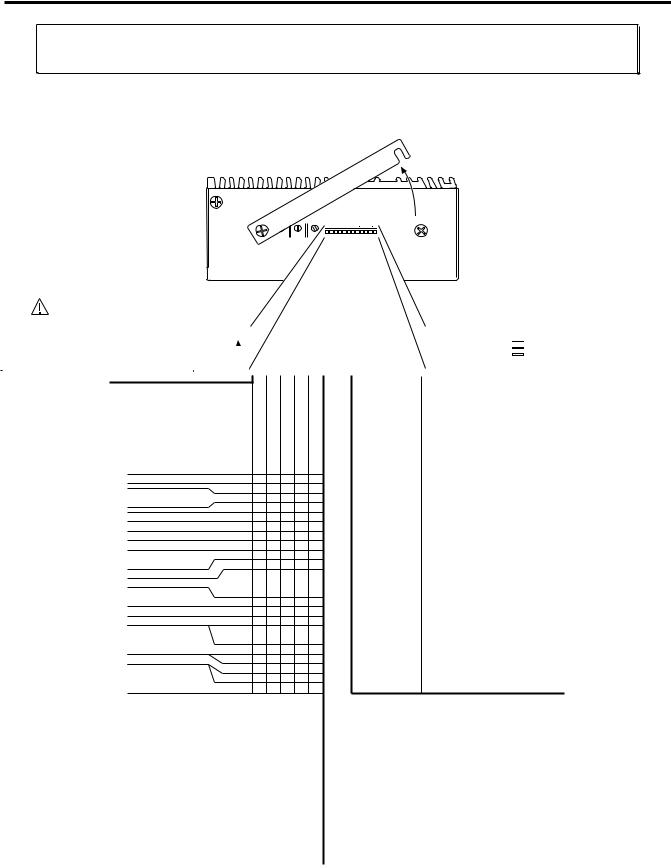
Changing the COM 2 Connector from RS-232 to RS-485
2 COM
|
|
+5V |
Rx+ |
|
|
GND |
Rx– |
|
|
||
|
|
Rx |
Tx+ |
|
|
||
|
|
Tx |
Tx– |
|
|
||
|
|
SHLD |
GND |
|
|
||
|
|
|
|
RS-485 (optional)
RS-232 (factory default)
RS-232C Users
The ZETA6104’s COM 2 port is factory configured for RS-232C communication (use the left-hand pin descriptions). If you do not need to use RS-485 communication, you may ignore this section and proceed to the Mounting instructions.
Remove the two retainer screws.
(one on the top of the chassis,
one on the bottom of the chassis) |
Heatsink |
Slide the chassis forward, then away from the heat sink.
(follow the dashed arrow)
Chassis 
Be careful not to catch the 50-pin header clips on the chassis.
Set the jumpers.
RS-232: Leave JU6 set to position 3 (factory default).
RS-485: Set jumper JU6 to position 1
(disables power-up messages, error messages, & echo).
COM 2 port for RS-232, set JU1-JU5 to position 3 (factory default).
COM 2 port for RS-485, set JU1-JU5 to position 1 (as illustrated). 
4-wire RS-485, set JU7 to position 3 (factory default).  (4-wire is full duplex: transmit and receive at the same time)
2-wire RS-485, set JU7 to position 1.
(2-wire is half duplex: transmit or receive at any time)
Set the DIP switches.
DIP switch #4: |
Rx Termination Resistor |
...........120 Ω |
DIP switch #3: |
Tx+ Bias Resistor..................... |
681 Ω |
DIP switch #2: |
Tx Termination Resistor........... |
120 Ω |
DIP switch #1: |
Tx– Bias Resistor..................... |
681 Ω |
N
O 1 2 3 4
NOTE: Set the switches to ON (as illustrated) to use the internal resistors. Do this for a single unit or for the last unit in a multi-drop only. If these resistor values are not appropriate for your application, set the switches to OFF and connect your own external resistors. See page 8 for resistor calculations and wiring instructions.
Reattach the chassis and replace the two retainer screws.
Chapter 1. Installation |
5 |
Mounting the ZETA6104
Before you mount the ZETA6104
Check the list below to make sure you have performed all the necessary configuration tasks that require accessing internal components (DIP switches, potentiometers, and jumpers). You may, however, be able to adjust DIP switches and pots after mounting, if you allow access to the top of the ZETA6104 chassis.
•Select motor current (DIP switches). If you ordered a ZETA motor with your system (e.g., ZETA6104-57-83) and you intend to use series motor winding, use the factory setting. If you need to change this setting, refer to page 4 for instructions.
•Select device address (DIP switches). If you are not connecting multiple ZETA6104 units in an RS-232C daisy chain or an RS-485 multi-drop, use the factory setting. If you need to change this setting, refer to page 4 for instructions.
•Select serial communication method (jumpers & DIP switches). If you are using RS-232C to communicate with the ZETA6104, use the factory settings. If you need to change these settings (i.e., for RS-485), refer to page 5 for instructions.
•Be aware that if you exercise the motor matching procedures on page 22, you will need to access the potentiometers at the top of the ZETA6104 chassis. (The motor matching procedures are placed after the Electrical Connections section of this manual because the process requires that you first understand how to connect the motor, serial communication, and AC power.)
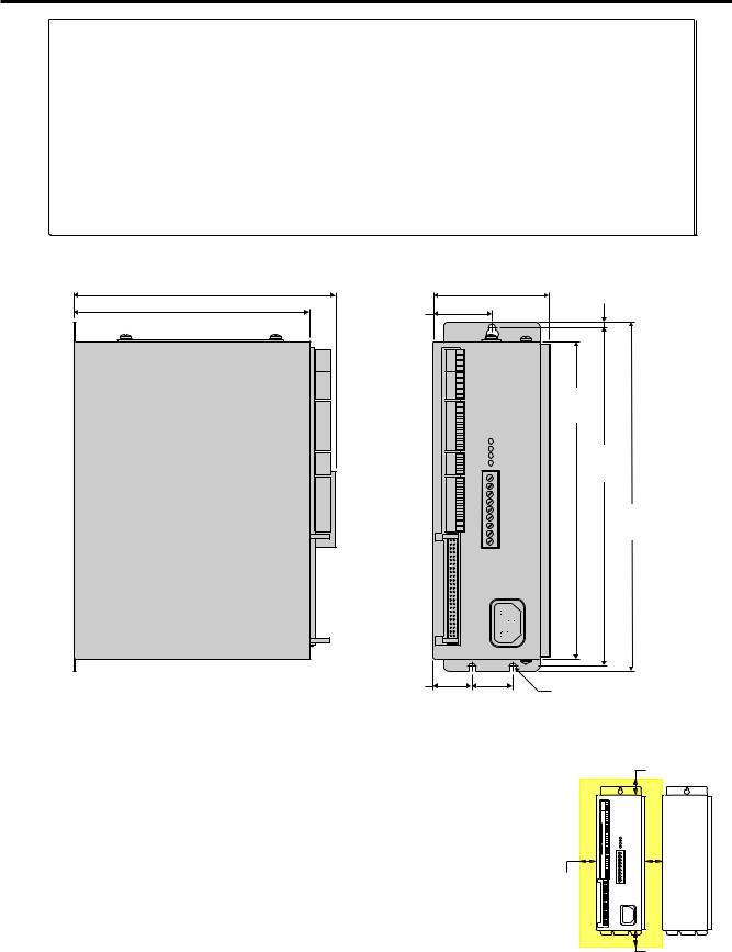
|
4.000 |
0.133 |
6.813 (173.1) |
(101.6) |
|
5.970 (151.6) |
1.465 |
(3.4) |
|
||
|
(37.2) |
|
8.000
(203.2)
8.600
(218.4)
8.850
(224.8)
Dimensions in inches (millimeters). |
0.965 |
|
3x Ø0.156 (3.9) |
|
(24.5) |
1.000 |
|||
|
(clearance for #6 (M3.5) |
(25.4) |
mounting screw) |
|
Environmental Temperature. Operate the ZETA6104 in ambient Considerations temperatures between 32°F (0°C) and 113°F (45°C). Provide a
minimum of 1 inch (25.4 mm) of unrestricted air-flow space around the ZETA6104 chassis (see illustration). The ZETA6104 will shut itself down if its internal sensor reaches 131°F (55°C).
Humidity. Keep below 95%, non-condensing.
Airborne Contaminants, Liquids. Particulate contaminants, especially electrically conductive material, such as metal shavings and grinding dust, can damage the ZETA6104 and the Zeta motor. Do not allow liquids or fluids to come in contact with the ZETA6104 or its cables.
Minimum Airflow Space = 1 inch
1.0 (25.4) |
1.0 |
(25.4) |
1.0 (25.4) |
6 ζ ZETA6104 Installation Guide
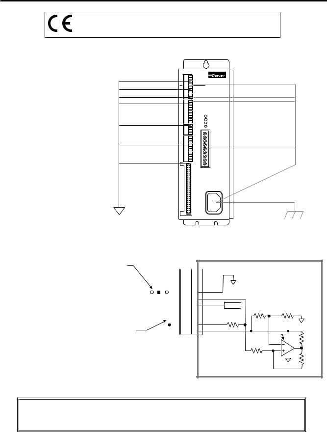
Electrical Connections
To install the ZETA6104 so that it is LVD compliant, refer also to the supplemental instructions in Appendix C. Appendix D provides guidelines on how to install the ZETA6104 in a manner most likely to minimize the ZETA6104’s emissions and to maximize the ZETA6104’s immunity to externally generated electromagnetic interference.
Grounding System
*The function of COM2’s terminals depends on whether it is configured for RS-232 (the factory default configuration) or for RS-485 (see page 5 for configuration).
NOTE: The inputs and outputs are isolated from the internal microprocessor, but are not isolated from the other inputs and outputs.
GND
GND (if COM2 is RS-232) *
GND (if COM2 is RS-485) *
GND
GND
GND
GND (even number pins)
Isolated
Ground
COM |
GND |
|
|
1 |
SHLD |
|
|
2COM |
|
|
|
GND |
|
|
|
|
SHLD |
GND |
|
|
SHLD |
|
|
|
GND |
|
|
ENCODER |
|
|
|
LIMITS |
GND |
|
|
|
|
MOTOR |
|
I/O |
GND |
|
|
|
|
EARTH |
|
12
I/OPROGRAMMABLE |
|
|
Compumotor |
49 |
Hz 50/60 |
VAC 132-95 |
POWERAC |
50 |
|
|
SHLD
SHLD (if COM2 is RS-232) *
SHLD
EARTH
Ground Pin
EARTH
Pulse Cut-Off (P-CUT) — Emergency Stop Switch
P-CUT connected to GND (normally-closed switch). |
|
|
|
|
I/O Connector |
||||||||
If this connection is opened, motion is killed and the |
|
|
|
|
|
|
|
|
|
|
|
|
TRG-A |
|
|
|
|
|
|
|
|
|
|
|
|
||
|
|
|
|
|
|
|
|
|
|
|
|
||
program in progress is terminated. |
|
|
|
|
|
|
|
|
|
|
|
|
TRG-B |
|
|
|
|
|
|
|
|
|
|
|
|
||
If the P-CUT input is not grounded when motion is |
|
|
|
|
|
|
|
|
|
|
|
|
|
|
|
|
|
|
|
|
|
|
|
|
|
OUT-A |
|
|
|
|
|
|
|
|
|
|
|
|
|
||
commanded, motion will not occur and the error message |
|
|
|
|
|
|
|
|
|
|
|
|
GND |
“WARNING: PULSE CUTOFF ACTIVE” will be displayed in |
|
|
|
|
|
|
|
|
|
|
|
|
P-CUT |
|
|
|
|
|
|
|
|
|
|
|
|
||
the terminal emulator. |
|
|
|
|
|
|
|
|
|
|
|
|
|
|
|
|
|
|
|
|
|
|
|
|
|
||
|
|
|
|
|
|
|
|
|
|
|
|
||
|
|
|
|
|
|
|
|
|
|
|
|
|
+5V |
|
|
|
|
|
|
|
|
|
|
|
|
|
OUT-P |
|
|
|
|
|
|
|
|
|
|
|
|
|
|
|
|
|
|
|
|
|
|
|
|
|
|
|
IN-P |
|
|
|
|
|
|
|
|
|
|
|
|
|
|
+5V connected to AUX-P and V_I/O (sourcing current). |
|
|
|
|
|
|
|
|
|
|
|
|
AUX-P |
|
|
|
|
|
|
|
|
|
|
|
|
V_I/O |
|
Provides +5V power to the P-CUT pull-up resistor. As an alternative, you can
connect AUX-P to an external supply of up to +24V (but do not use both the on-board +5V terminal and an external 5-24V supply). If V_I/O is connected to a +5V supply (on-board or external), AUX-P can be connected to a supply of up to +24V. If V_I/O is connected to an external +24V supply, AUX-P must also be connected to +24V (or to GND).
Switching levels depend on the voltage applied to V_I/O:
LOW £ 1/3 of V_I/O voltage; HIGH ³ 2/3 of V_I/O voltage
NOTE: AUX-P and V_I/O are also used by the HOM, NEG, POS & TRG inputs.
SINKING CURRENT: To make P-CUT (as well as HOM, NEG, POS & TRG) sink current, connect AUX-P to GND.
Internal Schematic
ISO GND
+5VDC
20.0 KΩ |
18.2 KΩ |
6.8 KΩ
LM 339
10.0 KΩ
12.1 KΩ
30.1 KΩ
CAUTION: You must select either the on-board +5V terminal or an external power supply to power the AUX-P pull-up resistor (for the P-CUT, HOM, NEG, POS, TRG-A, and TRG-B inputs). Connecting AUX-P to the +5V terminal and an external supply will damage the ZETA6104. (The same rule applies to the IN-P and OUT-P terminals, see page 14.)
Chapter 1. Installation |
7 |

Serial Communication
RS-232C Connections |
RS-232C Daisy-Chain Connections* |
|
|
Tx |
1COM |
Rx |
|
|
|
|
GND |
GND |
|
||
|
|
Rx |
|
Tx |
|
|
|
|
|
|
SHLD |
|
|
|
|
|
2 COM |
+5V |
Rx+ |
|
|
|
|
GND |
Rx– |
||
Serial Port Connection |
Rx |
Tx+ |
||||
Tx |
Tx– |
|||||
|
|
|
|
|||
9-Pin COM Port: |
|
25-Pin COM Port: |
|
SHLD |
GND |
|
|
|
|
|
|||
Pin 2 (Rx) |
Rx Pin 2 (Tx) |
|
|
|
||
Pin 3 (Tx) |
Tx |
Pin 3 (Rx) |
Rx |
|
|
|
GND |
Tx |
|
|
|||
Pin 5 (GND) |
Pin 7 (GND) |
|
|
|||
|
GND |
|
|
|||
|
|
|
|
|
||
NOTE: Maximum RS-232C cable length is 50 feet (15.25 meters)
RS-485 Connections (4-wire interface, plus ground)
|
Unit 0 |
Unit 1 |
Unit 2 |
||||||||||||
|
|
|
Rx |
|
|
|
|
|
Rx |
|
|
|
|
|
Rx |
|
|
|
Tx |
|
|
|
|
|
Tx |
|
|
|
|
|
Tx |
|
|
|
GND |
|
|
|
GND |
|
|
|
GND |
||||
|
|
|
|
|
|
|
|
|
|||||||
Tx |
|
|
SHLD |
|
|
|
SHLD |
|
|
|
SHLD |
||||
Rx |
|
|
|
|
|
|
|
|
|
|
|
|
|
|
|
GND |
|
|
|
|
|
|
|
|
|
|
|
|
|
|
|
Daisy Chain to a Computer or Terminal |
|||||||||||||||
|
Unit 0 |
Unit 1 |
Unit 2 |
|||||||||||
|
|
|
|
Rx |
|
|
|
|
Rx |
|
|
|
|
Rx |
|
|
|
|
Tx |
|
|
|
|
Tx |
|
|
|
|
Tx |
|
|
|
|
GND |
|
|
|
GND |
|
|
|
GND |
||
|
|
|
|
|
|
|
|
|
|
|||||
|
|
|
|
SHLD |
|
|
|
SHLD |
|
|
|
SHLD |
||
|
|
|
|
|
|
|
|
|
|
|
|
|
|
|
Stand-Alone Daisy Chain
*Be sure to set unique devices addresses for each unit. To set the address, use the DIP switch (see page 4),
or use the ADDR command (see 6000 Series Programmer’s Guide).
RS-485 Configuration
Before you can use RS-485 communication, you must reconfigure the COM 2 port by setting internal jumpers JU1-JU6 to position 1. 4-wire is default (to use 2-wire, set JU7 to position 1).
Refer to page 5 for instructions.
Unit #1
COM |
|
|
+5V |
Rx+ |
|
|
Rx |
Tx+ |
|
|
|
|
GND |
Rx– |
2 |
|
|
Tx |
Tx– |
|
|
|||
|
|
|||
|
|
|
||
|
|
|
SHLD GND |
|
|
|
|
||
|
|
|
|
|
Unit #2
COM |
|
|
|
+5V |
Rx+ |
|||
|
|
|
Rx |
Tx+ |
||||
2 |
|
|
|
GND |
Rx– |
|||
|
|
|
|
|
|
|
|
|
|
|
|
|
|
|
|
|
|
|
|
|
Tx |
Tx– |
|
|
||
|
|
|
|
|
||||
|
|
|
|
|
||||
|
|
|
|
|
||||
|
|
|
|
SHLD GND |
|
|||
|
|
|
|
|||||
|
|
|
|
|
|
|
|
|
Unit #3
COM |
|
|
|
+5V |
Rx+ |
|||
|
|
|
Rx |
Tx+ |
||||
2 |
|
|
|
GND |
Rx– |
|||
|
|
|
|
|
|
|
|
|
|
|
|
|
|
|
|
|
|
|
|
|
Tx |
Tx– |
|
|
||
|
|
|
|
|
||||
|
|
|
|
|
||||
|
|
|
|
|
||||
|
|
|
|
SHLD GND |
|
|||
|
|
|
|
|||||
|
|
|
|
|
|
|
|
|
Ground |
|
+5VDC |
Master |
|
Tx+ Unit
Tx– |
120 Ω |
|
|
Rx+ |
|
Rx– |
120 Ω |
|
|
Shield |
|
Calculating Resistor Values
Vcc
Ra
Vb |
Rc |
Balanced Cable. |
Rb |
Rd
5VDC |
120 Ω |
Unit #31 |
|
|
681Ω |
|
|
|
|
4 |
|
+5V |
Rx+ |
|
|
COM |
|||
|
23 |
|||
|
Rx |
Tx+ |
||
|
|
|
GND |
Rx– |
|
1 |
2 |
Tx |
Tx– |
681Ω |
O N |
|
SHLD GND |
|
120 Ω |
|
|
|
|
|
|
|
|
|
DIP switch selects internal resistor values (ON selects the resistor).
Use these resistors only for the last unit (or for a single unit).
If your application requires terminating resistors other than 120Ω, and/or bias resistors other than 681Ω, then make sure the internal DIP switches are set to OFF and connect your own external resistors. To calculate resistor values:
NOTE: Maximum RS-485 cable length is 4000 feet (1220 meters)
Example Assumptions: The cable's characteristic impedance (Zo) = 120Ω.
Rc and Rb are equal and are selected to match Zo (Rc = Rb = Zo = 120Ω).
Step 1 Calculate the equivalent resistance (Req)* of Rc / / Rb: Rc / / Rb = 120Ω / / 120Ω = 60Ω
Step 2 Calculate the pull-up and pull-down resistor values knowing that the FAILSAFE bias is 200mV and Vcc = 5V:
Vb = Vcc (Req / (Ra + Req + Rd)) solving for R' (defined as Ra + Rd) R' = ((Req) Vcc / Vb) - Req
R' = ((60Ω) 5V / 0.2V) - 60Ω = 1440Ω
Since Ra and Rd are equal, Ra = Rd = 1440Ω / 2 = 720Ω
Step 3 Recalculate the equivalent resistance of RC / / (Ra + Rd): Rc / / (Ra + Rd) = 120Ω / / (720Ω + 720Ω) = 110.77Ω
Since the equivalent resistance is close (within 10%) to the characteristic impedance of the cable (Zo), no further adjustment of resistor values is required.
* Actual calculation |
R1 R2 |
|
For further information, |
||
for equivalent resistance |
|
||||
(R1 + R2) |
|
consult a communications |
|||
(e.g., R |
1 |
/ / R ): |
|
||
|
2 |
|
|
interface reference. |
|
8 ζ ZETA6104 Installation Guide

Motor (ZETA and OS/RS motors only)
|
Motor Connector |
INTERLOCK |
|
ACENTERTAP |
|
A+ |
|
B+ MOTOR |
|
A– |
|
EARTH |
|
B– |
|
BCENTERTAP |
WARNING: Remove AC power |
INTERLOCK |
|
|
before connecting or disconnecting |
|
the motor. Lethal voltages are |
|
present on the screw terminals |
ZETA, OS and RS Motors
Specifications – see page 3. Speed/Torque curves – see page 10.
Considerations for series & parallel wiring – see page 10. Current settings – see page 4. Dimensions – see page 24. Cable extension – see table below.
ZETA & RSxxx-xxC10 motors include a rubber boot for safety.
Non-Compumotor Motors
If you intend to use a non-Compumotor motor, refer to Appendix B for connection instructions and current selection.
 ZETA, OS and RS Motor Connections
Series Connection
INTERLOCK |
Yellow |
|
Blue |
||
ACENTERTAP |
||
A+ |
Red |
|
Black |
||
A– |
||
Shield |
||
EARTH |
||
White |
||
B+ |
||
Green |
||
B– |
||
Orange |
||
BCENTERTAP |
||
|
||
INTERLOCK |
Brown |
|
|
Motor
Phase A |
Windings |
PM
Phase B
Windings
Do not lengthen or |
|
Shield is connected to the motor case and |
remove this jumper. |
|
is internally connected to the ground pin |
|
|
on the ZETA6104’s AC power connector. |
NOTE: ZETA motors are shipped from the factory wired to the connector in series.
Parallel Connection
INTERLOCK |
Red |
|
Blue |
||
ACENTERTAP |
||
Yellow |
||
A+ |
||
Black |
||
A– |
||
Shield |
||
EARTH |
||
White |
||
B+ |
||
Brown |
||
B– |
||
Orange |
||
BCENTERTAP |
||
Green |
||
INTERLOCK |
||
|
Motor
Phase A |
Windings |
PM
Phase B
Windings
See page 10 for guidelines about using a motor in parallel.
RSxxx-xxNPS and RSxxx-xxC10 Motor Connections
Series Connection |
Schematic View |
End Cover Removed |
|
|
INTERLOCK |
|
Phase A |
|
|
3 |
4 |
|
|
Windings |
|
|
||||
|
|
|
|
|
|||
ACENTERTAP |
|
|
|
|
|
||
Wire #1 |
1 |
|
|
|
6 |
8 |
|
A+ |
6 |
|
|
|
|||
Wire #3 |
|
|
|
|
|
||
|
PM |
|
|
|
|||
A– |
|
|
5 |
7 |
|||
|
Gnd (Grn/Ylw) |
5 |
|
|
|
||
EARTH |
|
|
Phase B |
1 |
2 |
||
Wire #2 |
|
|
|
||||
B+ |
3 |
|
|
Windings |
|
|
|
B– |
Wire #4 |
2 |
8 |
7 |
4 |
|
|
|
|
|
|||||
BCENTERTAP |
|
|
|
||||
|
|
|
|
|
|
|
|
INTERLOCK |
|
|
|
|
|
|
|
The green/yellow (Gnd) wire is for safety |
|
|
|
|
|
|
|
|
|
purposes. The shield connection to the motor |
|
|
|
|
|
|
|
|
|
case is for EMI purposes (the C10 cable kit |
Motor Terminal Number/Wire Number: |
|
Gnd |
1 |
3 |
2 |
4 |
|
|
provides hardware for the shield connection). |
|
|
|||||||
ZETA6104 Motor Connector Terminal: |
EARTH |
A+ |
A- |
B+ |
B- |
||||
C10 cable assembly instructions are provided |
|||||||||
|
|
|
|
|
|
|
|
||
in the C10 cable kit. |
|
|
|
|
|
|
|
|
|
Parallel Connection
INTERLOCK |
|
|
ACENTERTAP |
Wire #1 |
|
A+ |
||
Wire #3 |
||
A– |
||
Gnd (Grn/Ylw) |
||
EARTH |
||
Wire #2 |
||
B+ |
||
Wire #4 |
||
B– |
||
|
||
BCENTERTAP |
|
|
INTERLOCK |
|
Phase A
 Windings
1
6
PM
5
Phase B 3 Windings
2 |
8 |
4 |
|
7 |
3 |
4 |
6 |
8 |
5 |
7 |
1 |
2 |
|
The green/yellow (Gnd) wire is for safety |
|
|
|
|
|
|
|
|
|
purposes. The shield connection to the motor |
|
|
|
|
|
|
|
|
|
case is for EMI purposes (the C10 cable kit |
|
|
|
|
|
|
|
|
|
provides hardware for the shield connection). |
Motor Terminal Number/Wire Number: |
|
Gnd |
1 |
3 |
2 |
4 |
|
|
C10 cable assembly instructions are provided |
ZETA6104 Motor Connector Terminal: |
EARTH |
A+ |
A- |
B+ |
B- |
|||
in the C10 cable kit. |
|||||||||
|
|
|
|
|
|
|
|
||
|
|
|
|
|
|
|
|
||
Auto Current Standy Mode: Reduces motor current by 50% when step pulses from the ZETA6104 have stopped for one second (CAUTION: torque is also reduced). Full current is restored upon the first step pulse. Enable with the DAUTOS1 command; disable with the DAUTOSØ command (default is disabled). For more information, refer to the DAUTOS command in the 6000 Series Software Reference.
Extending ZETA Motor Cables
Standard length is 10 ft (3 m);
maximum extended length is 200 ft (61 m).
CAUTION: Cables longer than 50 feet (15 m) may degrade performance.
Max. Current |
< 100 ft (30 m) 100-200 ft (30-60 m) |
||||
Motor Type |
(amps) |
AWG |
mm2 |
AWG |
mm2 |
ZETA57-51(S) |
1.26 |
22 |
0.34 |
20 |
0.50 |
ZETA57-51(P) |
2.38 |
22 |
0.34 |
20 |
0.50 |
ZETA57-83(S) |
1.51 |
22 |
0.34 |
20 |
0.50 |
ZETA57-83(P) |
3.13 |
22 |
0.34 |
20 |
0.50 |
ZETA57-102(S) |
1.76 |
22 |
0.34 |
20 |
0.50 |
ZETA57-102(P) |
3.50 |
20 |
0.50 |
18 |
0.75 |
ZETA83-62(S) |
2.26 |
22 |
0.34 |
20 |
0.50 |
ZETA83-62(P) |
4.00 |
20 |
0.50 |
18 |
0.75 |
ZETA83-93(S) |
2.88 |
22 |
0.34 |
20 |
0.50 |
ZETA83-93(P) |
4.00 |
20 |
0.50 |
18 |
0.75 |
ZETA83-135(S) |
3.50 |
20 |
0.50 |
18 |
0.75 |
ZETA83-135(P) |
4.00 |
20 |
0.50 |
18 |
0.75 |
Extending OS and RS Motor Cables
-L10, -R10 & -C10 motors are shipped with 10 ft (3 m) cables; -FLY motor is shipped with 1 ft (0.3 m) flying leads.
-NPS motor does not include cable/leads; 10-foot: use 18 AWG (0.75 mm2) wire. LVD COMPLIANCE: Maximum DC resistance between the ZETA6104’s
“EARTH” terminal (“protective conductor terminal”) and motor body must not exceed 0.1 Ω. (This criteria must be taken into consideration when sizing cross-section (gage) for extended cable lengths.)
NON-LVD: Maximum extended length is 200 ft (61 m), but cables longer than 50 feet (15 m) may degrade performance. See table below for guidelines:
|
Max. Current |
< 100 ft (30 m) |
100-200 ft (30-60 m) |
||
Motor Type |
(amps) |
AWG |
mm2 |
AWG |
mm2 |
OS2HB(S) |
1.51 |
22 |
0.34 |
20 |
0.50 |
OS2HB(P) |
3.01 |
22 |
0.34 |
20 |
0.50 |
OS21B(S) |
1.88 |
22 |
0.34 |
20 |
0.50 |
OS21B(P) |
3.75 |
20 |
0.50 |
18 |
0.75 |
OS22B(S) |
2.14 |
22 |
0.34 |
20 |
0.50 |
OS22B(P) |
4.00 |
20 |
0.50 |
18 |
0.75 |
RS31B(S) |
2.26 |
22 |
0.34 |
20 |
0.50 |
RS31B(P) |
4.00 |
20 |
0.50 |
18 |
0.75 |
ZETA83-93(S) |
2.88 |
22 |
0.34 |
20 |
0.50 |
ZETA83-93(P) |
4.00 |
20 |
0.50 |
18 |
0.75 |
ZETA83-135(S) |
3.50 |
20 |
0.50 |
18 |
0.75 |
ZETA83-135(P) |
4.00 |
20 |
0.50 |
18 |
0.75 |
(S) = Series Configuration (P) = Parallel Configuration
NOTE: Rated current in wire sizes shown may result in a maximum temperature rise of 18°F (10°C) above ambient.
Chapter 1. Installation |
9 |
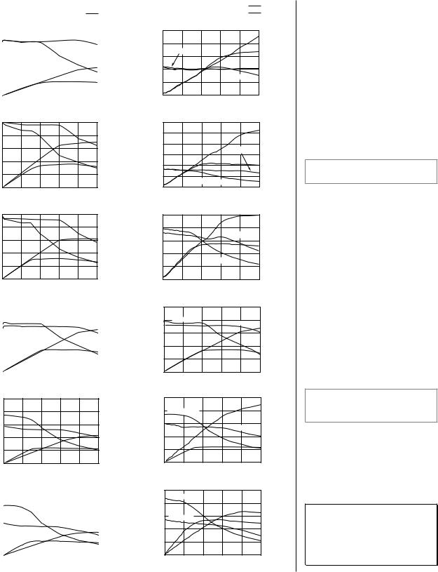
Selecting Series or Parallel Motor Wiring
Zeta Motor Curves |
|
|
|
|
= Torque |
||||||||
|
|
|
|
|
|
|
|
|
|
|
|
|
|
|
|
|
|
|
|
|
|
|
|
|
|
|
= Power |
|
oz-in (N-m) |
|
ZETA57–51 |
|
|
|
|
Power |
|||||
|
75 |
(0.53) |
|
|
|
|
|
|
watts (hp) |
||||
|
|
|
|
|
|
|
|
Parallel |
|
|
|
|
|
Torque |
60 |
(0.42) |
|
|
|
|
|
|
|
|
|
|
|
|
|
|
|
|
Series |
|
|
|
|
|
|||
45 |
(0.32) |
|
|
|
|
|
|
|
|
|
|
||
|
|
|
|
|
|
|
|
|
|
|
Parallel |
||
|
|
|
|
|
|
|
|
|
|
|
|||
|
|
|
|
|
|
|
|
|
|
|
|
|
|
|
|
|
|
|
|
|
|
|
|
|
|
||
|
30 |
(0.21) |
|
|
|
|
|
|
|
|
|
129 (0.18) |
|
|
|
|
|
|
|
|
|
|
|
||||
|
15 |
(0.11) |
|
|
|
|
|
|
|
|
|
|
Series |
|
|
|
|
|
|
|
|
|
|
||||
|
|
|
|
|
|
|
|
|
|
|
|
60 (0.08) |
|
|
|
0 |
|
|
|
|
|
|
|
|
|
|
|
|
|
|
|
|
|
|
|
|
|
|
|
|
|
|
|
0 |
10 |
20 |
30 |
40 |
50 |
||||||
Speed-RPS
Torque
oz-in (N-m)
125 (0.88)
100 (0.70)
75 (0.53)
50 (0.35)
25 (0.18)
0
|
|
ZETA57–83 |
Power |
||
|
|
watts (hp) |
|||
|
|
|
|
Parallel |
|
|
|
Series |
|
|
Parallel |
|
|
|
|
|
175 (0.23) |
|
|
|
|
|
Series |
|
|
|
|
|
80 (0.11) |
0 |
10 |
20 |
30 |
40 |
50 |
Speed-RPS
Torque
oz-in (N-m)
150 (1.05)
120 (0.84)
90 (0.63)
60 (0.42)
30 (0.21)
0
|
|
ZETA57–102 |
|
Power |
|
|
|
|
watts (hp) |
||
|
|
|
Parallel |
|
|
|
|
Series |
|
|
Parallel |
|
|
|
|
|
186 (0.25) |
|
|
|
|
|
Series |
|
|
|
|
|
80 (0.11) |
0 |
10 |
20 |
30 |
40 |
50 |
Speed-RPS
Torque
oz-in (N-m)
200 (1.40)
160 (1.12)
120 (0.84)
80 (0.56)
40 (0.28)
0
|
|
ZETA83–62 |
|
|
|
Power |
|||
|
|
|
|
|
watts (hp) |
||||
|
|
|
|
|
|
|
|
|
|
|
|
|
|
|
Parallel |
|
|
|
Parallel |
|
|
|
|
|
|
|
|
|
260 (0.35) |
|
|
|
|
|
|
|
|
|
|
|
|
|
|
Series |
|
|
|
|
|
|
|
|
|
|
|
|
|
|
Series |
|
|
|
|
|
|
|
|
|
|
|
|
|
|
|
|
|
|
|
|
|
|
|
|
|
|
|
|
|
120 (0.16) |
|
|
|
|
|
|
|
|
|
|
|
|
|
|
|
|
|
|
|
|
0 |
10 |
20 |
30 |
40 |
50 |
||||
Speed-RPS
Torque
oz-in (N-m)
400 (2.80)
320 (2.24)
240 (1.68)
160 (1.12)
80 (0.56)
0
|
|
ZETA83–93 |
|
Power |
|
|
|
|
watts (hp) |
||
|
|
Series |
|
|
|
|
|
Parallel |
|
|
Parallel |
|
|
|
|
|
350 (0.47) |
|
|
|
|
|
Series |
|
|
|
|
|
180 (0.24) |
0 |
10 |
20 |
30 |
40 |
50 |
|
|
|
|
|
|
Speed-RPS |
|
|
|
|
||
|
oz-in (N-m) |
|
ZETA83–135 |
|
|
|
Power |
|||||
|
500 |
(3.50) |
|
|
|
|
|
watts (hp) |
||||
|
400 |
(2.80) |
|
|
|
|
|
|
|
|
|
|
Torque |
|
|
Series |
|
|
|
|
|
|
|
||
|
|
|
|
|
|
|
|
|
|
|
||
300 |
(2.10) |
|
|
|
|
|
|
|
|
|
|
|
|
|
Parallel |
|
|
|
|
|
|
|
|
||
|
|
|
|
|
|
|
|
|
|
|
|
|
|
200 |
(1.40) |
|
|
|
|
|
|
|
|
|
Parallel |
|
|
|
|
|
|
|
|
|
|
355 (0.48) |
||
|
|
|
|
|
|
|
|
|
|
|
|
|
|
100 |
(0.70) |
|
|
|
|
|
|
|
|
|
Series |
|
|
|
|
|
|
|
|
|
|
|||
|
|
|
|
|
|
|
|
|
|
|
|
193 (0.26) |
|
|
0 |
|
|
|
|
|
|
|
|
|
|
|
|
0 |
10 |
20 |
30 |
40 |
50 |
|||||
Speed-RPS
O & R Motor Curves |
= Torque |
||||||
|
|
|
|
|
|
|
= Power |
|
oz-in (N-m) |
|
OS2HB |
|
Power |
||
|
100 |
(0.70) |
|
|
watts (hp) |
||
|
|
|
|
|
|
||
|
|
|
|
|
|
|
Parallel |
|
80 |
(0.56) |
|
|
|
|
91 (0.12) |
|
|
|
|
|
|
||
Torque |
|
|
Parallel (3.01Apk) |
|
|
|
Series |
60 |
(0.43) |
|
|
|
|
68 (0.09) |
|
|
|
|
|
|
|||
|
40 |
(0.28) |
|
|
|
|
|
|
|
|
|
|
|
Series (1.51Apk) |
|
|
20 |
(0.14) |
|
|
|
|
|
|
|
0 |
10 |
20 |
30 |
40 |
50 |
|
|
0 |
|||||
Speed-RPS
Torque
oz-in (N-m)
300 (2.13)
205 (1.42)
200 (1.42)
150 (1.07)
100 (0.71)
50 (0.36)
0
OS21B |
Power |
|
watts (hp) |
||
|
||
|
Parallel |
|
|
263 (0.36) |
Parallel (3.75Apk)
Series 102 (0.14)
Series (1.88Apk)
0 |
10 |
20 |
30 |
40 |
50 |
Speed-RPS
Torque
oz-in (N-m)
200 (1.42)
160 (1.14)
120 (0.85)
80 (0.56)
40 (0.28)
0
OS22B |
Power |
watts (hp) |
|
|
Parallel |
|
199 (0.27) |
|
Parallel (4Apk) |
|
Series |
|
104 (0.14) |
Series (2.26Apk)
0 |
10 |
20 |
30 |
40 |
50 |
Speed-RPS
|
oz-in (N-m) |
||
|
200 |
(1.40) |
|
Torque |
160 |
(1.12) |
|
120 |
(0.84) |
||
|
|||
|
80 |
(0.56) |
|
|
40 |
(0.28) |
|
|
|
0 |
|
|
|
0 |
|
|
oz-in (N-m) |
||
|
400 |
(2.80) |
|
Torque |
320 |
(2.24) |
|
240 |
(1.68) |
||
|
160 |
(1.12) |
|
|
80 |
(0.56) |
|
|
|
0 |
|
|
|
0 |
|
|
oz-in (N-m) |
||
|
500 |
(3.50) |
|
Torque |
400 |
(2.80) |
|
300 |
(2.10) |
||
|
200 |
(1.40) |
|
|
100 |
(0.70) |
|
|
|
0 |
|
|
|
0 |
|
|
RS31B |
|
Power |
|
|
|
watts (hp) |
||
Series (2.26Apk) |
|
|
Parallel (4.0Apk) |
|
|
|
|
Parallel |
|
|
|
|
|
230 (0.31) |
|
|
|
|
Series |
|
|
|
|
120 (0.16) |
10 |
20 |
30 |
40 |
50 |
|
Speed-RPS |
|
|
|
|
RS32B |
|
Power |
|
|
|
watts (hp) |
||
|
|
|
|
Parallel |
Series (2.88Apk) |
|
|
|
359 (0.48) |
|
|
|
|
|
|
|
|
Parallel (4Apk) |
|
|
|
|
|
Series |
|
|
|
|
186 (0.25) |
10 |
20 |
30 |
40 |
50 |
|
Speed-RPS |
|
|
|
|
RS33B |
|
Power |
|
|
|
watts (hp) |
||
Series (3.5Apk) |
|
|
|
|
|
|
|
|
Parallel |
Parallel (4Apk) |
|
|
|
327 (0.44) |
|
|
|
|
|
|
|
|
|
Series |
|
|
|
|
246 (0.33) |
10 |
20 |
30 |
40 |
50 |
|
Speed-RPS |
|
|
|
Use series wiring if your application permits.
ZETA motors come from the factory with a permanently attached motor cable wired to the motor connector for series motor current. The O and R Series motors have flying leads or pigtails that you must wire to the motor connector yourself. The operating temperature of a motor connected in series will be lower than that of a motor connected in parallel. Typically, series connections work well in high torque/low speed applications.
Series motor wiring diagrams are provided on page 9.
When to use parallel wiring.
At higher speeds, a motor connected in parallel will produce more torque than the same motor connected in series. Use caution, however, because the operating temperature of the motor in parallel will be much hotter. If you operate your motor in parallel, measure motor temperature under actual operating conditions. If the motor exceeds its maximum case temperature, reduce the duty cycle to limit motor heating. Compumotorsupplied motors have maximum case temperatures of 212°F (100°C).
To wire the motor for parallel motor current, refer to the wiring diagrams on page 9.
Non-Compumotor Motors: If you are using a nonCompumotor motor, refer to Appendix B for connection instructions and current-select DIP switch settings.
1 0 ζ ZETA6104 Installation Guide
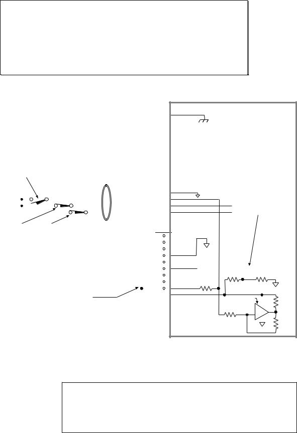
End-of-Travel and Home Limit Inputs
N O T E S
•CAUTION: Use either the on-board +5V terminal or an external power supply to power the AUX-P pull-up resistor (using both will damage the ZETA6104).
•Motion will not occur until you do one of the following:
-Install end-of-travel (POS & NEG) limit switches.
-Disable the limits with the LHØ command (recommended only if load is not coupled).
-Change the active level of the limits with the LHLVL command.
•Refer to the Basic Operation Setup chapter in the 6000 Series Programmer’s Guide for in-depth discussions about using end-of-travel limits and homing.
CONNECTIONS & INTERNAL SCHEMATICS
|
|
|
|
|
|
|
|
ENCODER Connector |
|
|
|
|
Internal Schematic |
||||||||||
|
|
|
|
|
|
|
|
|
|
|
|
|
SHLD |
|
|
|
|
|
|
|
|
|
|
|
|
|
|
|
|
|
|
|
|
|
|
|
|
|
|
|
|
|
|
|
|
|
|
HOM connected to GND (normally-open switch). |
|
|
|
|
|
GND |
Chassis Ground |
|
|
|
|
|
|
|
|||||||||
|
|
|
|
|
|
|
|
|
|
|
|
||||||||||||
|
|
|
|
|
|
|
|
|
|
|
|
||||||||||||
The home limit input is used during a homing move, which |
|
|
|
|
|
Z- |
|
|
|
|
|
|
|
|
|
|
|||||||
|
|
|
|
|
|
|
|
|
|
|
|
|
|
|
|||||||||
is initiated with the HOM command. After initiating the |
|
|
|
|
|
Z+ |
|
|
|
|
|
|
|
|
|
|
|||||||
homing move, the controller waits for the home switch to |
|
|
|
|
|
B- |
|
|
|
|
|
|
|
|
|
|
|||||||
|
|
|
|
|
|
|
|
|
|
|
|
|
|
|
|||||||||
close, indicating that the load has reached the “home” |
|
|
|
|
|
B+ |
|
|
|
|
|
|
|
|
|
|
|||||||
|
|
|
|
|
|
|
|
|
|
|
|
|
|
|
|||||||||
reference position. The active level (default is active low) |
|
|
|
|
|
|
|
|
|
|
|
|
|
|
|
||||||||
|
|
|
|
|
A- |
|
|
|
|
|
|
|
|
|
|
||||||||
can be changed with the HOMLVL command. You can |
|
|
|
|
|
|
|
|
|
|
|
|
|
|
|
||||||||
|
|
|
|
|
|
|
|
|
|
|
|
|
|
|
|||||||||
also use an encoder’s Z channel pulse, in conjunction with |
|
|
|
|
|
A+ |
|
|
|
|
|
|
|
|
|
|
|||||||
the home switch, to determine the home position (this |
|
|
|
|
|
+5V |
|
|
|
|
|
|
|
|
|
|
|||||||
|
|
|
|
|
|
|
|
|
|
|
|
|
|
|
|||||||||
feature is enabled with the HOMZ1 command). |
|
|
|
|
|
|
|
|
|
|
|
|
|
|
|
|
|||||||
LIMITS Connector |
GND |
Iso Ground |
|
|
|
|
|
|
|
||||||||||||||
|
|
|
|
|
|
|
|
|
|
|
|
|
|
|
|||||||||
|
|
|
|
|
|
|
|
|
|
|
|
|
|
|
|||||||||
|
|
|
|
|
|
|
|
|
|
|
|
|
|
|
|
|
|
|
|
||||
|
|
|
|
|
|
|
|
|
|
|
|
|
HOM |
|
|
|
|
|
|
|
|
|
|
|
|
|
|
|
|
|
|
|
|
|
|
|
|
|
|
|
|
|
|
|
|
|
|
|
|
|
|
|
|
|
|
|
|
|
|
|
NEG |
|
|
Similar circuits for NEG |
|
||||||
|
|
|
|
|
|
|
|
|
|
|
|
|
|||||||||||
|
|
|
|
|
|
|
|
|
|
|
|
|
POS |
|
|
and POS inputs. |
|
||||||
|
|
|
|
|
|
|
|
|
|
|
|
|
|||||||||||
|
|
|
|
|
|
|
|
|
|
|
|
|
|||||||||||
|
|
|
|
|
|
|
|
|
|
|
|
|
|
|
|
|
|
|
|
|
|
|
|
POS & NEG connected to GND (normally-closed switches). |
I/O Connector |
|
|
|
|
|
|
|
|
|
|
|
|||||||||||
Mount each switch such that the load forces it to open before it |
|
|
|
|
|
TRG-A |
|
|
|
|
|
|
|
|
|
|
|||||||
reaches the physical travel limit (leave enough room for the load to |
|
|
|
|
|
TRG-B |
|
|
|
|
|
|
|
|
|
|
|||||||
|
|
|
|
|
|
|
|
|
|
|
|
|
|
|
|||||||||
stop). When the load opens the switch, the axis stops at the decel |
|
|
|
|
|
|
|
|
|
|
|
|
|
|
|
||||||||
|
|
|
|
|
OUT-A |
|
|
|
|
|
|
|
|
|
|
||||||||
|
|
|
|
|
|
|
|
|
|
|
|
|
|
|
|||||||||
value set with the LHAD command. The motor will not be able to |
|
|
|
|
|
Iso |
|
|
|
|
|
|
|
||||||||||
|
|
|
|
|
|
|
|
|
|
|
|
||||||||||||
move in that same direction until you execute a move in the opposite |
|
|
|
|
|
GND |
Ground |
|
|
|
|
|
|
|
|||||||||
direction and clear the limit by closing the switch (or you can disable |
|
|
|
|
|
P-CUT |
|
|
|
|
|
|
|
|
|
|
|||||||
|
|
|
|
|
|
|
|
|
|
|
|
|
|
|
|||||||||
the limits with the LHØ command, but this is recommended only if the |
|
|
|
|
|
+5V |
|
|
|
|
|
|
|
|
|
|
|||||||
motor is not coupled to the load). The active level (default is active |
|
|
|
|
|
+5VDC |
20.0 KΩ |
18.2 KΩ |
|||||||||||||||
|
|
|
|
|
|
|
|||||||||||||||||
|
|
|
|
|
OUT-P |
|
|||||||||||||||||
low) can be changed with the LHLVL command. |
|
|
|
|
|
|
|||||||||||||||||
|
|
|
|
|
IN-P |
6.8 KΩ |
|
|
|
|
|
|
|
||||||||||
|
|
|
|
|
|
|
|
|
|
|
|
|
|
|
|
|
|
|
|
||||
|
|
|
|
|
|
|
|
|
|
|
|
|
|
|
|
|
|
|
|
||||
|
|
|
|
|
|
|
|
|
|
|
|
|
AUX-P |
|
|
|
|
|
|
|
|
|
|
|
|
|
|
|
|
|
|
|
|
|
|
|
|
|
|
|
|
|
|
|
|
|
|
+5V connected to AUX-P and V_I/O (sourcing current). |
|
|
|
|
|
V_I/O |
|
|
|
LM 339 |
|
|
|||||||||||
|
|
|
|
|
|
|
|
|
|
||||||||||||||
|
|
|
|
|
|
|
|
|
|
|
|||||||||||||
Provides +5V power to the POS, NEG, and HOM input pull-up resistors. As an alternative, |
|
|
|
|
|
|
|
|
|
10.0 KΩ |
|||||||||||||
you can connect AUX-P to an external supply of up to +24V (but do not use both the on-board +5V |
|
|
|
|
|
|
|
|
|
|
|
||||||||||||
|
|
|
|
|
|
|
|
|
|
|
|||||||||||||
terminal and an external 5-24V supply). If V_I/O is connected to a +5V supply (on-board or external), |
|
|
|
|
|
|
|
|
|
|
|
||||||||||||
AUX-P can be connected to a supply of up to +24V. If V_I/O is connected to an external +24V supply, |
|
|
12.1 KΩ |
|
|
|
|
|
|
|
|||||||||||||
AUX-P must also be connected to +24V (or to GND). |
|
|
|
|
|
|
|
|
|
|
|
|
|
|
30.1 KΩ |
||||||||
Switching levels depend on voltage at V_I/O (LOW £ 1/3 of V_I/O volts; |
HIGH ³ 2/3 of V_I/O volts). |
|
|
|
|
|
|
|
|
|
|
|
|||||||||||
NOTE: AUX-P and V_I/O are also used by the P-CUT & TRG inputs. |
|
|
|
|
|
|
|
|
|
|
|
|
|
|
|
|
|||||||
SINKING CURRENT: To make the limit inputs (as well as P-CUT & TRG) sink current, connect AUX-P to GND.
PIN OUTS & SPECIFICATIONS (4-pin LIMITS Connector)
Name |
In/Out |
Description |
GND |
— |
Isolated ground. |
HOM |
IN |
Home limit input. |
NEG |
IN |
Negative-direction end- |
|
|
of-travel limit input. |
POS |
IN |
Positive-direction end- |
|
|
of-travel limit input. |
|
|
|
Specification for all limit inputs
•Powered by voltage applied to V_I/O terminal (switching levels: Low £1/3 of V_I/O voltage,
High ³2/3 of V_I/O voltage). V_I/O can handle 5-24V with max. current of 100mA. Internal 6.8 KW pull-ups to AUX-P terminal—connect AUX-P to power source (+5V terminal or an external 5-24V supply) to source current, or connect AUX-P to GND to sink current; AUX-P can handle 0-24V with max. current of 50mA. Voltage range for these inputs is 0-24V.
•Active level for HOM is set with HOMLVL (default is active low, requires n.o. switch).
•Active level for POS & NEG is set with LHLVL (default is active low, requires n.c. switch).
Chapter 1. Installation |
1 1 |
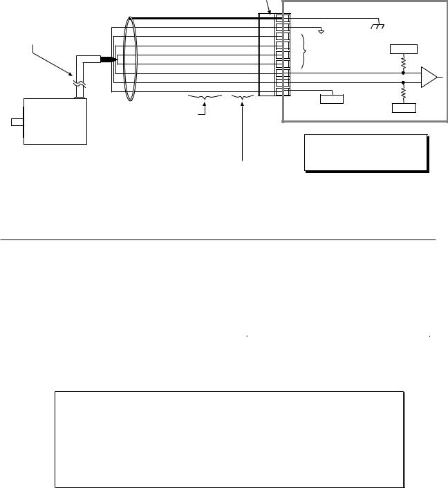
Encoder |
|
|
|
|
|
|
|
|
CONNECTIONS |
& |
INTERNAL SCHEMATICS |
|
|
|
|
||
|
|
|
|
ENCODER Connector |
|
|||
|
|
Shield |
Shield |
Shield |
|
|
Internal Schematic |
|
|
|
SHLD |
|
|||||
|
|
Ground |
Black |
Black |
|
|||
|
|
GND |
|
Chassis Ground |
||||
Max. Cable Length is 100 feet. |
Z Channel – |
Orange/White |
(n/a) |
Isolated Ground |
||||
Z- |
|
|||||||
Use 22 AWG wire. |
|
|
||||||
|
Z Channel + |
Orange |
Blue |
|
|
|||
|
|
Z+ |
Same Circuit |
|
||||
|
|
B Channel – |
Green/White |
(n/a) |
+1.8VDC |
|||
|
|
B- |
as A Channel |
|
||||
|
|
B Channel + |
Green |
Brown |
|
|||
|
|
B+ |
|
22 KΩ |
||||
|
|
A Channel – |
Brown/White |
(n/a) |
|
|||
|
|
A- |
|
|
||||
|
|
A Channel + |
Brown |
White |
|
|
||
|
|
A+ |
|
|
||||
|
|
+5VDC |
Red |
Red |
|
|
||
|
|
+5V |
|
22 KΩ |
||||
|
|
|
|
|
+5VDC |
|||
|
|
|
|
|
|
|
||
Incremental |
|
|
|
|
|
|
+5VDC |
|
|
Colors for Compumotor-supplied Encoders: |
|
|
|
|
|||
Encoder |
|
-E Series encoders |
|
|
|
|
|
|
|
-RE encoder on OS motor (OSxxx-xxx-RE) |
|
|
|
|
|||
|
|
-RC encoder on OS motor (OSxxx-xxx-RC) |
|
|
|
|
||
|
|
-EC encoder on RS motor (RSxxx-xxx-EC) |
|
|
NOTE |
|
||
|
|
|
|
|
|
|
||
|
|
If you are using a single-ended encoder, |
Colors for -HJ encoder on OS motor (OSxxx-xxx-HJ). |
|
leave the A-, B-, and Z- terminals on the |
|
ZETA6104 unconnected. |
|
|
|
PIN OUTS & SPECIFICATIONS (9-pin ENCODER Connector)
Pin Name |
In/Out |
Description |
|
|
SHLD |
----- |
Shield—Internally connected to chassis ground (earth). |
|
|
GND |
----- |
Isolated logic ground. |
|
|
Z– |
IN |
Z– Channel signal input. |
|
|
Specification for all encoder inputs |
|
|||
Z+ |
IN |
Z+ Channel signal input. |
|
|
Differential comparator accepts two-phase quadrature |
|
|||
|
|
|
|
|
B– |
IN |
B– Channel quadrature signal input. |
incremental encoders with differential (recommended) or |
|
B+ |
IN |
B+ Channel quadrature signal input. |
single-ended outputs. Max. frequency is 1.6 MHz. |
|
Minimum time between transitions is 625 ns. |
|
|||
|
|
|
|
|
A– |
IN |
A– Channel quadrature signal input. |
TTL-compatible voltage levels: Low £ 0.4V, High ³ 2.4V. |
|
A+ |
IN |
A+ Channel quadrature signal input. |
Maximum input voltage is 5VDC. |
|
|
|
|||
+5V |
OUT |
+5VDC output to power the encoder. |
|
|
|
|
|
|
|
Requirements for Non-Compumotor Encoders
•Use incremental encoders with two-phase quadrature output. An index or Z channel output is optional. Differential outputs are recommended.
•It must be a 5V (< 200mA) encoder to use the ZETA6104’s +5V output. Otherwise, it must be separately powered with TTL-compatible (low £ 0.4V, high ³ 2.4V) or open-collector outputs.
•The decoded quadrature resolution should be less than the motor resolution by a factor of four to take advantage of the ZETA6104’s position maintenance capability.
1 2 z ZETA6104 Installation Guide
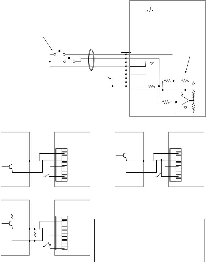
Trigger Inputs
TRG-A/B connected to GND (normally-open switches). |
|
ENCODER Connector |
SHLD |
|
|
|
Internal Schematic |
|||||||||||||||||||||||
|
|
|
|
|
|
|
|
|
|
|
|
|
|
|
|
|||||||||||||||
|
|
|
|
|
|
|
|
|
|
|
|
|
|
|
|
|||||||||||||||
The active level (default is active low) can be changed with the |
|
|
|
|
|
GND |
Chassis Ground |
|
|
|
|
|
|
|
|
|||||||||||||||
|
|
|
|
|
|
|
|
|
|
|
|
|
||||||||||||||||||
INLVL command. |
|
|
|
|
|
Z- |
|
|
|
|
|
|
|
|
|
|
|
|||||||||||||
|
|
|
|
|
|
|
|
|
|
|
|
|
|
|||||||||||||||||
These inputs are like the general-purpose inputs on the 50-pin |
|
|
|
|
|
Z+ |
|
|
|
|
|
|
|
|
|
|
|
|||||||||||||
|
|
|
|
|
|
|
|
|
|
|
|
|
|
|
|
|||||||||||||||
header. The differences are (1) the triggers are pulled up via |
|
|
|
|
|
B- |
|
|
|
|
|
|
|
|
|
|
|
|||||||||||||
|
|
|
|
|
|
|
|
|
|
|
|
|
|
|||||||||||||||||
the AUX-P pull-up terminal and powered by the voltage applied |
|
|
|
|
|
B+ |
|
|
|
|
|
|
|
|
|
|
|
|||||||||||||
|
|
|
|
|
|
|
|
|
|
|
|
|
|
|||||||||||||||||
to the V_I/O terminal; and (2) the triggers can be programmed |
|
|
|
|
|
|
|
|
|
|
|
|
|
|
|
|
|
|||||||||||||
|
|
|
|
|
A- |
|
|
|
|
|
|
|
|
|
|
|
||||||||||||||
|
|
|
|
|
|
|
|
|
|
|
|
|
|
|||||||||||||||||
with the INFNCi-H command to function as position capture |
|
|
|
|
|
|
|
|
|
|
|
|
|
|
|
|
||||||||||||||
|
|
|
|
|
|
|
|
|
|
|
|
|
|
|||||||||||||||||
inputs and registration inputs. |
|
|
|
|
|
A+ |
|
|
|
|
|
|
|
|
|
|
|
|||||||||||||
|
|
|
|
|
|
|
|
|
|
|
|
|
|
|
|
|
|
|
+5V |
|
|
|
|
|
|
|
|
|
|
|
|
|
|
|
|
|
|
|
|
|
|
|
|
|
|
|
|
|
|
|
|
|
|
|
|
|
|
|
|
|
|
|
|
|
|
|
|
|
|
|
|
|
|
|
|
|
|
|
|
|
|
|
|
|
|
|
|
|
|
|
|
|
|
|
|
|
|
|
|
|
|
|
|
|
|
|
I/O Connector |
TRG-A |
|
|
|
|
|
|
|
|
|
|
|
||||
|
|
|
|
|
|
|
|
|
|
|
|
|
|
|
|
|
|
|
|
|
|
|
|
|
||||||
|
|
|
|
|
|
|
|
|
|
|
|
|
|
|
|
|
|
|
|
|
|
Similar circuit for TRG-A. |
|
|||||||
|
|
|
|
|
|
|
|
|
|
|
|
|
|
|
|
|
|
|
TRG-B |
|
|
|
|
|
|
|
|
|
|
|
|
|
|
|
|
|
|
|
|
|
|
|
|
|
|
|
|
|
|
|
|
|
|
|
|
|
|
|
|
|
|
|
|
|
|
|
|
|
|
|
|
|
|
|
|
|
|
|
|
|
|
|
|
|
|
|
|
|
|
|
|
|
|
|
|
|
|
|
|
|
|
|
|
|
|
|
|
|
|
|
|
|
|
|
|
|
|
|
|
|
|
|
|
|
|
|
|
|
|
|
|
|
|
|
|
|
|
|
|
|
|
|
OUT-A |
|
|
|
|
|
|
|
|
|
|
|
|
|
|
|
|
|
|
|
|
|
|
|
|
|
|
|
|
|
|
|
|
|
|
|
|
|
|
|
|
|
|
|
|
|
|
|
|
|
|
|
|
|
|
|
|
|
|
|
|
|
|
|
|
|
|
|
|
|
|
|
|
|
|
|
|
|
|
|
|
|
|
|
|
|
|
|
|
|
|
|
|
GND |
Iso |
|
|
|
|
|
|
|
|
||
|
|
|
|
|
|
|
|
|
|
|
|
|
|
|
|
|
|
|
|
|
|
|
|
|
|
|
||||
|
|
|
|
|
|
|
|
|
|
|
|
|
|
|
|
|
|
|
P-CUT |
Ground |
|
|
|
|
|
|
|
|
||
|
|
|
|
|
|
|
|
|
|
|
|
|
|
|
|
|
|
|
|
|
|
|
|
|
|
|
||||
|
|
|
|
|
|
|
|
|
|
|
|
|
|
|
|
|
|
|
|
|
|
|
|
|
|
|
|
|
|
|
|
|
|
|
|
|
|
|
|
|
|
|
|
|
|
|
|
|
|
+5V |
|
|
|
|
|
|
|
|
|
|
|
+5V connected to AUX-P and V_I/O (sourcing current). |
|
|
|
|
+5VDC |
20.0 KΩ |
18.2 KΩ |
|||||||||||||||||||||||
|
|
|
|
OUT-P |
|
|||||||||||||||||||||||||
|
|
|
||||||||||||||||||||||||||||
Provides +5V power to the TRG-A & TRG-B input pull-up resistors. As an alternative, |
|
|
|
|
|
|
|
|
|
|
|
|
|
|
|
|||||||||||||||
|
|
|
|
IN-P |
6.8 KΩ |
|
|
|
|
|
|
|
|
|||||||||||||||||
you can connect AUX-P to an external supply of up to +24V (but do not use both the |
|
|
|
|
|
|
|
|
|
|
|
|
||||||||||||||||||
|
|
|
|
|
|
|
|
|
|
|
||||||||||||||||||||
on-board +5V terminal and an external 5-24V supply). If V_I/O is connected to a +5V |
|
|
|
|
AUX-P |
|
|
|
|
|
|
|
|
|
|
|
||||||||||||||
|
|
|
|
|
|
|
|
|
|
|
|
|
|
|
||||||||||||||||
|
|
|
|
|
|
|
|
|
|
|
|
|
|
|||||||||||||||||
supply (on-board or external), AUX-P can be connected to a supply of up to +24V. |
|
|
|
|
V_I/O |
|
|
|
LM 339 |
|
|
|
||||||||||||||||||
|
|
|
|
|
|
|
|
|
|
|
|
|
|
|
|
|
|
|
|
|
|
|
|
|
|
|||||
If V_I/O is connected to an external +24V supply, AUX-P must also be connected to |
|
|
|
|
|
|
|
|
|
|
10.0 KΩ |
|||||||||||||||||||
+24V (or to GND). |
|
|
|
|
|
|
|
|
|
|
||||||||||||||||||||
|
|
|
|
|
|
|
|
|
|
|
|
|||||||||||||||||||
Switching levels depend on voltage at V_I/O (LOW £ 1/3 of V_I/O volts; HIGH ³ 2/3 of V_I/O volts). |
|
|
12.1 KΩ |
|
|
|
|
|
|
|
|
|||||||||||||||||||
NOTE: AUX-P and V_I/O are also used by the HOM, NEG, POS & P-CUT inputs. |
|
|
|
|
|
|
|
|
30.1 KΩ |
|||||||||||||||||||||
|
|
|
|
|
|
|
|
|
|
|||||||||||||||||||||
|
|
|
|
|
|
|
|
|
|
|
|
|
|
|
|
|
|
|
|
|
|
|
|
|
|
|
|
|
||
SINKING CURRENT: To make the trigger inputs (as well as HOM, NEG, POS & P-CUT) sink |
|
|
|
|
|
|
|
|
|
|
|
|
||||||||||||||||||
current, connect AUX-P to GND. |
|
|
|
|
|
|
|
|
|
|
|
|
||||||||||||||||||
Connection to a Sinking Output Device
Electronic Device |
ZETA6104 |
The output should be able to sink at least 1mA of current.
Out 5-24 Volts
Output
Ground |
I/O Connector
|
TRG-A |
|
TRG-B |
|
OUT-A |
|
GND |
|
P-CUT |
|
+5V |
|
OUT-P |
|
IN-P |
Pulled up |
AUX-P |
to +5V |
V_I/O |
(sourcing) |
(see schematic |
|
drawing above) |
Connection to a Sourcing Output Device
Electronic Device |
ZETA6104 |
V1
 R1
R1
Output
Out 5-24 Volts
Ground |
I/O Connector
|
TRG-A |
|
|
TRG-B |
|
|
OUT-A |
|
|
GND |
|
|
P-CUT |
|
|
+5V |
|
|
OUT-P |
|
|
IN-P |
|
Pulled |
AUX-P |
|
down to |
V_I/O |
|
ground |
(see schematic |
|
(sinking) |
||
drawing above) |
Connection to a Combination of Sinking & Sourcing Outputs
Electronic Device |
ZETA6104 |
V1 |
I/O Connector |
|
|
||
R1 |
TRG-A |
|
|
TRG-B |
|
Output |
OUT-A |
|
GND |
||
|
||
Out 5-24 Volts |
P-CUT |
|
R |
+5V |
|
Ground |
OUT-P |
|
|
IN-P |
|
Pulled up |
AUX-P |
|
V_I/O |
||
to +5V |
||
(sourcing) |
(see schematic |
|
|
drawing above) |
Typical value for R = 450Ω (assuming R1 = 0)
Note: The value of R may vary depending on the value of R1 and V1.
If you will be connecting to a combination of sourcing and sinking outputs, connect AUX-P to +5-24V to accommodate sinking output devices. Then for each individual input connected to a sourcing output, wire an external resistor between the ZETA6104’s trigger input terminal and ground (see illustration). The resistor provides a path for current to flow from the device when the output is active.
PROGRAMMING TIP
Connecting to a sinking output? Set the trigger input’s active level to low with the INLVL command (Ø = active low, default setting).
Connecting to a sourcing output? Set the trigger input’s active level to high with the INLVL command (1 = active high).
Thus, when the output is active, the TIN status command will report a “1” (indicates that the input is active), regardless of the type of output that is connected.
For details on setting the active level and checking the input status refer to the INLVL and TIN command descriptions in the 6000 Series Software Reference.
Chapter 1. Installation |
1 3 |
Loading...