


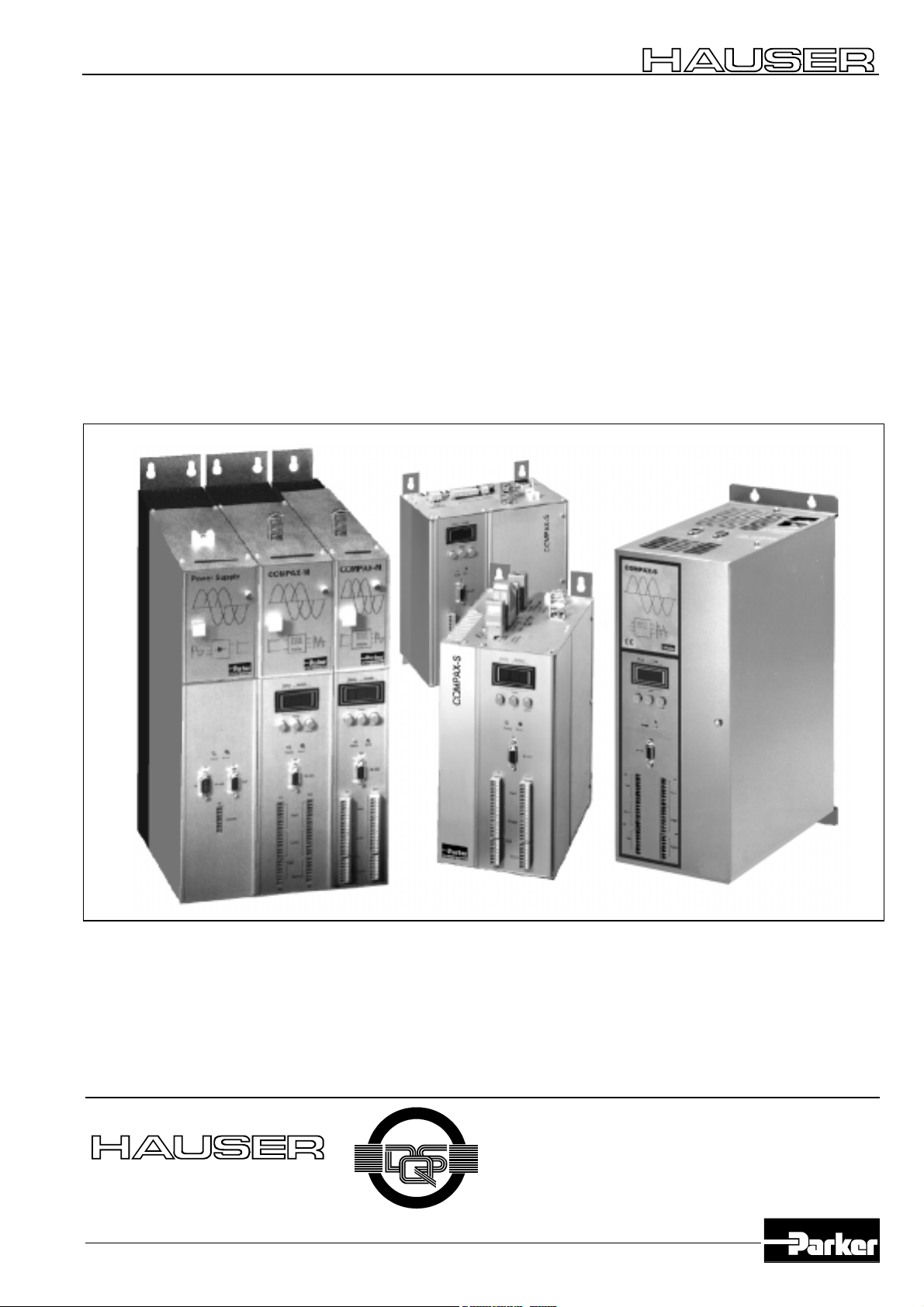
Hauser COMPAX 25 S F1 Series
Parker Hauser COMPAX 25 S F1 Series, Hauser COMPAX 45 S Series, Hauser COMPAX 25 S Series, Hauser COMPAX 45 S F5 Series, Hauser COMPAX 25 S F5 Series Operating Instructions Manual
...
COMPAX-M/S - RS485 - Option (F1, F5)
Operating Instructions
RS485 - Option (F1, F5)
Bus User Guide
For software versions V1.20 September 97
I
T
F
I
R
E
E
C
DIN E N ISO 90 01
We automate motion
Subject to technical change. Data represents the technical status at the time going to the press. 08.12.00 13:17 192-040026 N5
Q
U
A
L
Reg. Nr. 36 38
D
T
I
S
T
Y
Y
S
Parker Hannifin GmbH
EMD HAUSER
Robert-Bosch-Str. 22
D-77656 Offenburg, Germany
Phone: +49 (0)781 / 509-0
M
E
Fax: +49 (0)781 / 509-176
http://www.parker-emd.com
Parker Hannifin plc
EMD Digiplan
21 Balena Close
Poole, Dorset. BH17 7DX UK
Phone: +44 (0)1202 / 69-9000
Fax: +44 (0)1202 / 69-5750
http://www.parker-emd.com
COMPAX-M/S - RS485 - Option
Table of contents
1. Description of the RS485-interface ..............................2
2. RS485-Bus...................................................................3
2.1 Bus wiring ............................................................. 3
2.1.1 RS485 master at option F5..........................3
2.1.2 Via RS232-converter and option F1 - ..........4
2.1.3 Position plan of the cables...........................5
3. Device settings.............................................................6
3.1 Device address.....................................................6
3.2 Baud rate .............................................................. 6
3.3 RS485 operating mode.........................................6
3.3.1 Adjustment of operation mode at ASCII -
transmission .................................................6
3.3.2 Adjustment of field-bus protocol by option F56
3.3.3 Block-Check Character (BCC)..................... 6
3.3.4 Timeout monitoring ......................................6
4. Transmission protocol .................................................. 7
4.1 Frame format for transmitting from PC to
COMPAX ..............................................................7
4.2 Meaning of the various trans-mission elements... 7
4.3 Frame format of the COMPAX response .............7
4.4 Binary data transmission via RS485 ....................8
4.4.1 Meaning of the binary command code.........8
4.5 Program examples ...............................................9
4.5.1 BASIC program with BCC............................9
4.5.2 BASIC program without BCC.....................10
5. Parameters for the RS485 interface...........................11
6. Special error messages relating to the RS485 interface11
This documentation applies to the following devices:
!
COMPAX 25XXS with option F1 or F5
!
COMPAX 45XXS with option F1 or F5
!
COMPAX 85XXS with option F1 or F5
!
COMPAX P1XXM with option F1, or F5 without option N1
!
COMPAX 02XXM with option F1 or F5
!
COMPAX 05XXM with option F1 or F5
!
COMPAX 15XXM with option F1 or F5
"XX": any version number
"F1/F5": RS485 option
"N1": single-phase supply (not possible in combination
with F1)
Key to device designation:
e.g.: COMPAX 0260M:
COMPAX:Name
02: rated power class
60: version, e.g. "00" = standard device
M: device type where "M" = multi-axes device and
"S" = single-axis device
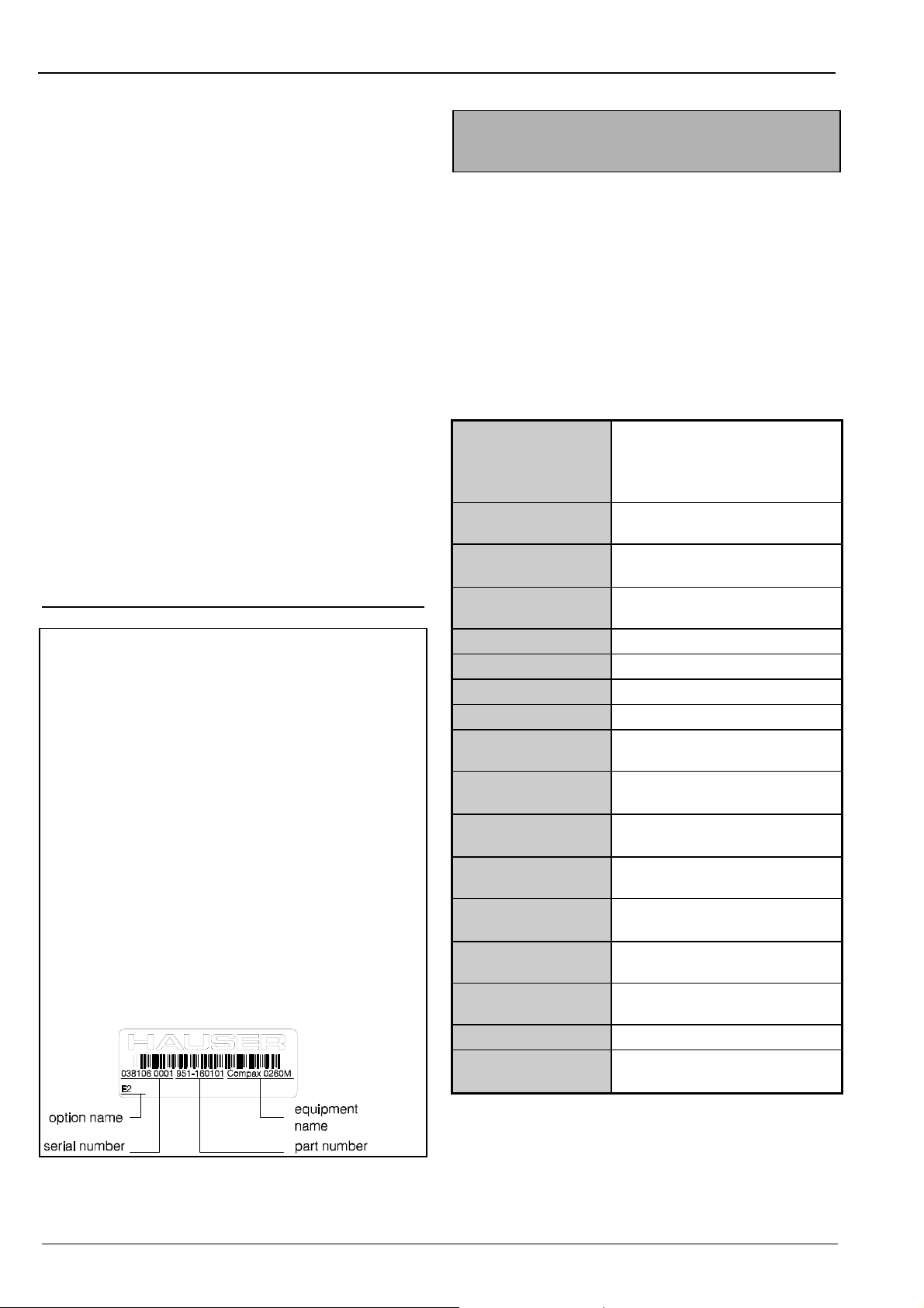
HAUSER-name-plate
The name-plate is located on the top of the device and
comprises:
1. Description of the RS485interface
You can, via the RS232 interface of a industrial computer
and an RS232-RS485 bus converter, communicate with up
to 31 COMPAX devices. The following functions are
supported:
!
direct command input and execution in on-line mode,
!
reading out status values,
!
reading and writing program blocks (full command set
available),
!
reading and writing parameters, and
!
transmission of control statements.
Interface parameter of the ASCII protocol:
Interface: F1: 4 wire for RS232-master
via RS232/RS485 converter.
F5: 2 wire - RS485
Baud rate:
Maximum line
length:
Devices on bus:
Address:
Character length:
Start bit:
Stop bit:
Parity:
Hardware
handshake:
Software
handshake:
Timeout monitoring
Block-Check
Character (BCC)
Input buffer:
Output buffer:
Data format:
End-of-text
character (ETX):
150 up to 115200, set by
parameter P195
1,2 kilometers
up to 31 COMPAX devices can be
connected
set by parameter P194
8 bits
1 bit
1 bit
none / even / odd, set by
parameter P196
no
XON/XOFF, set by parameter
P196
can be activated, by parameter
P196
can be activated, improves
transmission reliability
command string, maximum 40
characters
status string, maximum 40
characters
ASCII, except for BCC
CR: carriage return (0D hex)
2
2. RS485-Bus
2.1 Bus wiring
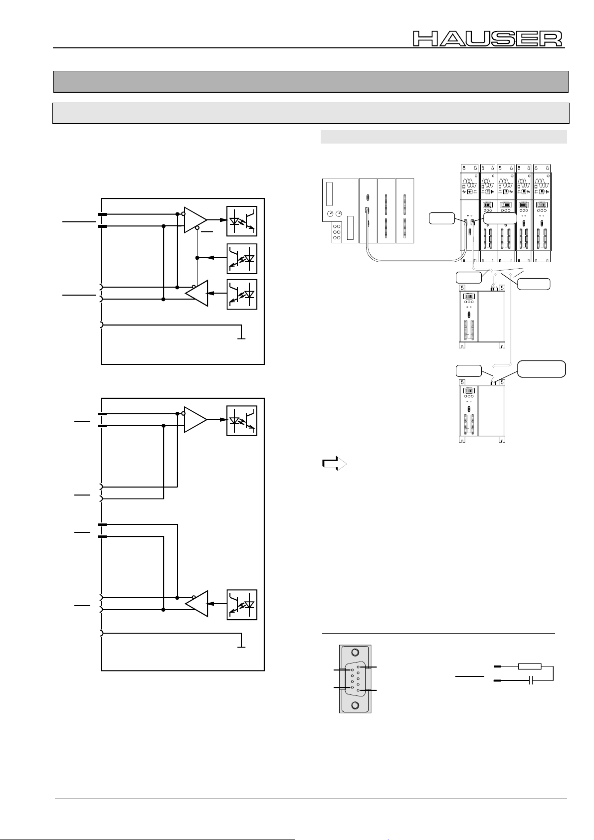
plug assignment of RS485-bus
COMPAX S: X5 / X7
NMD: X6 / X7
option F5
COMPAX S (NMD)
RxD/TxD
RxD/TxD
RxD/TxD
RxD/TxD
COMPAX -
GND
option F1
RxD
RxD
X5(6)/2
X5(6)/7
RE
DE
X7/2
X7/7
X7/3
COMPAX S (NMD)
X5(6)/1
X5(6)/6
COMPAX -
GND
2.1.1 RS485 master at option F5
NMD CPXM with Option F5
SPS
Siemens SPS Siemens SPS Siemens SPS Siemens SPS
RS 485
X1 X2
24 V
GND
ERDE
RS 485
RS 485
CPX S with option F5
CPX S with option F5
E1
A1
E2
A2
E3
A3
E4
A4
E5
A5
E6
A6
E7
A7
E8
A8
E9
A9
E10
A10
E11
A11
E12
A12
E13
E14
E15
E16
E17
E18
E19
E20
E21
E22
X6 IN X7 OUT
A13
A14
A15
A16
A17
A18
A19
A20
A21
A22
ΗΑΥΣΕΡ
ΠΟΩΕΡ ΣΥΠΠΛΨ
Ρεαδψ Ερρορ
Ξ6 Ξ7
ΡΣ485ΙΝ ΟΥΤ
Ξ8
X5 IN
StatusN umber
Value
-+Enter
Ready Error
X6
X8 X10
Input
Output
Test
Control
X9 X11
X5 IN
StatusN umber
Value
-+Enter
Ready Error
X6
X8 X10
Input
Output
Test
Control
X9 X11
ΗΑΥΣΕΡ
∆ΙΓΙΤΑΛ
ΧΟΜΠΑΞ−Μ
Στατυσ Νυµ βερ
ςαλυε
−+Εντερ
Ρεαδψ Ερρορ
Ξ6
ΡΣ232
Ξ8 Ξ10
Χοντρολ
Ινπυτ
Ουτπυτ
Τεστ
Χοντρολ
Ξ9 Ξ11
HAUSER
COMPAX-S
RS232
HAUSER
COMPAX-S
RS232
ΗΑΥΣΕΡ
∆ΙΓΙΤΑΛ
ΧΟΜΠΑΞ−Μ
Στατυσ Νυµβερ
ςαλυε
−+Εντερ
Ρεαδψ Ερρορ
Ξ6
ΡΣ232
Ξ8 Ξ10
Ινπυτ
Ουτπυτ
Τεστ
Χοντρολ
Ξ9 Ξ11
ΗΑΥΣΕΡ
ΗΑΥΣΕΡ
∆ΙΓΙΤΑΛ
∆ΙΓΙΤΑΛ
ΧΟΜΠΑΞ−Μ
ΧΟΜΠΑΞ−Μ
ΣτατυσΝυµβερ
Στατυσ Νυµβερ
ςαλυε
ςαλυε
−+Εντερ
−+Εντερ
Ρεαδψ Ερρορ
Ρεαδψ Ερρορ
Ξ6
Ξ6
ΡΣ232
ΡΣ232
Ξ8 Ξ10
Ξ8 Ξ10
Ινπυτ
Ινπυτ
Ουτπυτ
Ουτπυτ
Τεστ
Τεστ
Χοντρολ
Χοντρολ
Ξ9 Ξ11
Ξ9 Ξ11
SSK13/..
X7 OUT
to further
X7
bus subscribers
RxD
RxD
TxD
TxD
TxD
TxD
COMPAX -
GND
X7/1
X7/6
X5(6)/2
X5(6)/7
X7/2
X7/7
X7/3
COMPAX -
GND
Within a system group of COMPAX M and a power
module, the CAN-bus-signals are transmitted via the
already existing ribbon cable connection.
possible connections with SSK13/..:
!
power module X7 (OUT) → power module X6 (IN)
!
power module X7 (OUT) → COMPAX S X5 (IN)
!
COMPAX S X7 (OUT) → power module X6 (IN)
!
COMPAX S X7 (OUT) → COMPAX S X5 (IN)
bus termination option F5
the last device of the bus system must be terminated by a
resistor in order to guarantee interference-free operation.
F5: 120Ω and 10nF between X7/2 and X7/7 at power module
or at COMPAX S.
X7
120
6
9
1
5
RxD/TxD
RxD/TxD
2
7
9 pin sub-D male plug-connector
9 pin sub-D case
Ω
10nF
3
COMPAX-M/S - RS485 Option
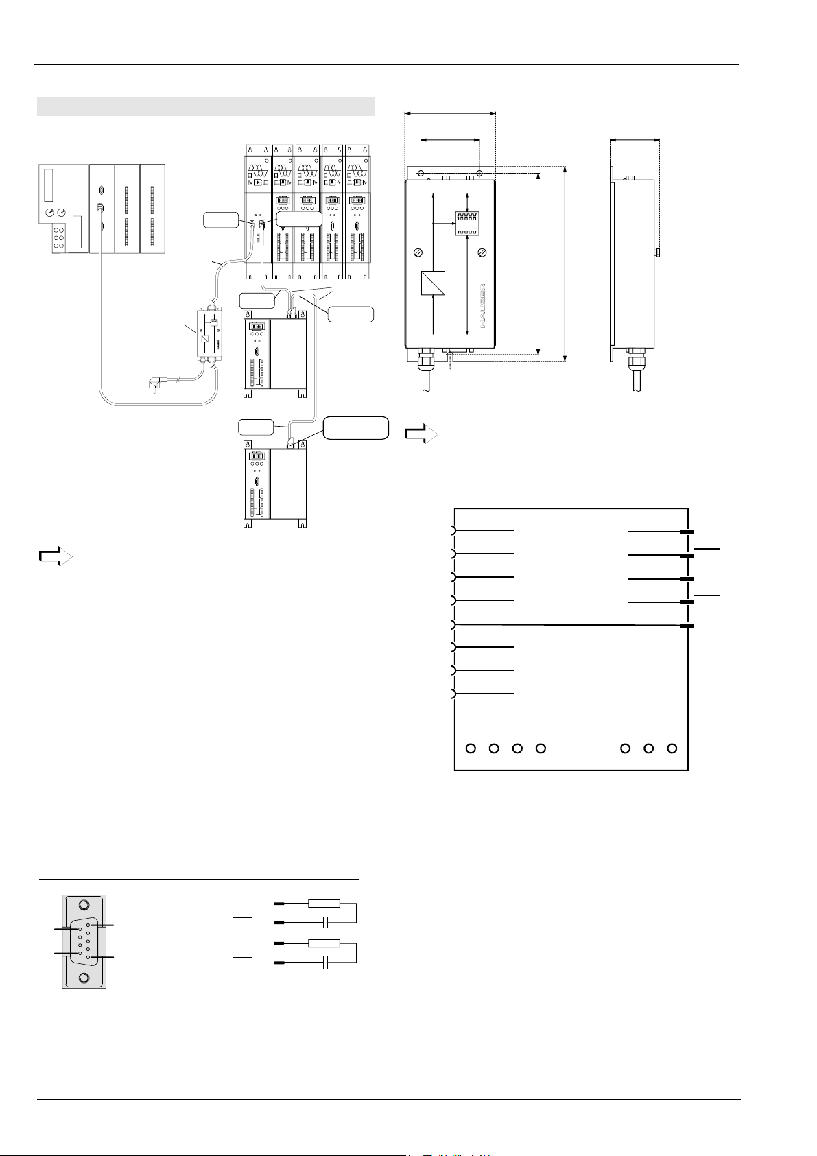
2.1.2 Via RS232-converter and option F1
NMD CPXM with option F1
Siemens SPS Siemens SPS Siemens SPS Siemens SPS
E1
A1
E2
A2
E3
A3
E4
A4
E5
A5
E6
A6
E7
A7
E8
A8
E9
A9
E10
A10
E11
A11
E12
A12
E13
A13
E14
A14
E15
A15
E16
A16
E17
A17
E18
A18
E19
A19
E20
A20
E21
A21
E22
A22
X6 IN
X1 X2
RS 485
RS 232
24 V
GND
ERDE
RS 485
SSK13/..
SPS
RS232 - RS485-
converter SSU1
Power on RS 485
AC / DC
Power
AC / DC
H1
5V DC
In a system group comprising a number of COMPAX
devices and a power module (NMD), the RS485
signals are transferred over the already existing
ribbon-cable connections.
possible connections with SSK13/..:
!
converter SSU1 → power module X6 (IN)
or
!
converter SSU1 → COMPAX S X5 (IN)
!
power module X7 (OUT) → power module X6 (IN)
!
power module X7 (OUT) → COMPAX S X5 (IN)
!
COMPAX S X7 (OUT) → power module X6 (IN)
!
COMPAX S X7 (OUT) → COMPAX S X5 (IN)
bus termination option F1
In order to guarantee interference-free operation, the last
device of the bus system must be terminated by 2 resistors.
F1: 120Ω and 10nF between X7/1 and X7/6 and X7/2 and
X7/7 at power module or at COMPAX S.
RS232 - RS485-converter: SSU1/01
X7
6
9
1
5
9 pin sub-D male plug-connector
9 pin sub-D case
HAUSER
HAUSER
HAUSER
HAUSER
HAUSER
DIGITAL
DIGITAL
DIGITAL
POWER SUPPLY
X6 X7
Ready Error
RS485IN OUT
X8
Control
COMPAX-M
StatusN umber
Value
-+Enter
Ready Error
X6
X7 OUT
RS232
X8 X10
Input
Output
Test
Control
X9 X11
COMPAX-M
Status Number
Value
-+Enter
Ready Error
X8 X10
Input
Output
Test
X9 X11
X6
RS232
Control
DIGITAL
COMPAX-M
COMPAX-M
StatusN umber
StatusNu mber
Value
Value
-+Enter
-+Enter
Ready Error
Ready Error
X6
X6
RS232
RS232
X8 X10
X8 X10
Input
Input
Output
Output
Test
Test
Control
Control
X9 X11
X9 X11
SSK13/..
X5 IN
X1
Status Number
COMPAX-S
HAUSER
Value
-+Enter
SSU
Ready Error
X6
X8 X10
X9 X11
RS232
Input
Output
Test
Control
X2
RS 232
X5 IN
Status Number
COMPAX-S
HAUSER
Value
-+Enter
Ready Error
X6
RS232
X8 X10
Input
Output
Test
Control
X9 X11
RxD
1
RxD
6
2
TxD
7
TxD
120
120
Ω
Ω
X7 OUT
CPX S with
option F1
to further
X7
bus subscribers
CPX S with
option F1
10nF
10nF
85
56
H1
X1
Power on RS 485
5V DC
AC/DC
X2
Power
RS 232
AC / DC
170
SSU
182
46
Attention!
The converter can only be used together with option
F1 (4 wire)!
plug assignment SSU1/01
SSU1/01
RxD
TxD
DTR
DSR
GND
RTS
CTS
+5V
X2/2
X2/3
X2/4
RS232 RS485
X2/6
X2/5
X2/7
X2/8
X2/9
X1/1
X1/6
X1/2
X1/7
X1/3
TxD
TxD
RXD
RXD
GND
X3 X4
/1 /2 /3 /4 /1 /2 /3
230V 110V N PE +24V 0V PE
Fixing: 3 screws M4.
the converter is fed via a power line (3m) by 230V AC.
the power supply can be adjusted to 110 V AV and 24 V DC.
. For doing this, the housing must be opened and the feed
lines have to be clamped as follows:
230V AC: X3/1 (L1); X3/3 (N) X3/4 (PE) (standard)
110V AC: X3/2 (L1); X3/3 (N) X3/4 (PE)
24V DC: X4/1 (+24V); X4/2 (0V) X4/3 (PE)
4
 Loading...