

Page 1

Pluto User Manual v1.38 Page 1 of 66
Version 1.38
21 October 2013
Pandora Technology sales@pandoratek.org
United Kingdom www.pandora-int.com October 2013
Page 2

Pluto User Manual v1.38 Page 2 of 66
PLUTO WARRANTY STATEMENT
Limited Warranty: The Pluto unit you have purchased includes a warranty on all electronic items of the
unit and manufacturing defects for a period of one year from the original shipment date. This Limited
warranty applies only to Pandora Technology branded hardware products sold or leased from Pandora
Technology [Starbow Ltd.], it's subsidiaries and authorised resellers or distributors.
During the lifetime of the product the Customer is authorised to download from our website any
software and/or firmware updates that are intended for the Model and Version of the Pluto unit
purchased. This will include bug fixes and feature revisions as detailed in the release notes that
accompany the update.
Exclusive Remedy: Subject to any conditions listed below the sole obligation of Pandora Technology
[Starbow Ltd.] under this Warranty is (at no extra charge) to correct, repair or replace the Equipment
(or part of it) to prevent a re occurrence of a particular defect during the warranty period.
Notification of Warranty claim: If a customer believes that the equipment is faulty in any way then the
customer should contact Pandora technology directly by phone or email at the addresses given below
with an full and accurate description of the problem. If after investigation Pandora Technology
determines that the equipment is faulty then it will be serviced or repaired according to the provisions
of the warranty. All repairs are carried out at our UK facility and it is the responsibility of the customer
to ensure that the equipment is properly packed and returned to us carriage paid.
Conditions:
The Limited Warranty does not cover the following:
– Cosmetic Damage
– Damage to any software applications or programmes, data or removable media.
– Damage due to :
(1) acts of God, accident or disaster, or any reason beyond Pandora Technology's reasonable control.
(2) Negligence or misuse including (but not limited to) failure to use the Equipment for its normal purpose of in
accordance with Pandora Technology's instructions on it's proper use and maintenance.
(3) Improper operation and maintenance of the Equipment (including unauthorized alterations and/or modifications by
anyone other than a Pandora Technology authorised service agent).
(4) Operation of the equipment with non-compatible equipment, products, accessories power supplies or attachments
outside of the published environmental and electrical parameters.
The Customers failure to notify Pandora Technology of a fault with the equipment during the Warranty Period, or the continued use of
the equipment after a fault has been detected, shall constitute an unqualified acceptance of such Equipment and a waiver by the
Customer of all claims thereto.
All Equipment (including any parts and components of Equipment) replaced by Pandora Technology becomes the property of Pandora
Technology to be kept or disposed of at Pandora Technology's discretion. Customers shall not be compensated or otherwise credited in
respect thereof.
From time to time Pandora Technology may release major new software features, product updates and/or new hardware revisions
Pandora Technology reserves the right to charge for these accordingly.
Please note that it is the responsibility of the customer to ensure that any firmware or software updates or patches are installed
according to the published instructions and that any updates are applied to the correctly matching hardware.
Limitation of Liability: The liability of Pandora Technology, if any, and Customers sole and exclusive remedy for damages for any claim of
any kind whatsoever shall not be greater than the actual purchase price of the Equipment with respect to which the claim is made. In
no event shall Pandora Technology be liable to the Customer for any special, indirect, incidental or consequential damages of any kind
including (but not limited to) compensation, reimbursement or damages on account of the loss of present or prospective profits or for
any other reason whatsoever.
For Further information or to report any problems please contact ….
Pandora Technology [Starbow Ltd.]
Ingress Coach House
Capability Way
Greenhithe
Kent DA9 9GY
UK
tel: +44 1322 374700 fax: +44 1322 374701
email: service@pandoratek.org
Pandora Technology sales@pandoratek.org
United Kingdom www.pandora-int.com October 2013
Page 3

Pluto User Manual v1.38 Page 3 of 66
Table of Contents
Chapter 1: Introduction............................................................................................................................3
1.1 What's new since v1.37.................................................................................................................3
1.2 Control Overview..........................................................................................................................4
Chapter 2: Hardware Overview................................................................................................................5
Chapter 3: Software Control.....................................................................................................................7
3.1 Main Pluto Window ......................................................................................................................7
3.2 Networking....................................................................................................................................8
3.3 Look Up Tables and How to Upload Them.................................................................................10
3.4 Copying and Moving LUTs.........................................................................................................12
3.5 Setup Tab.....................................................................................................................................13
3.6 Routing Tab.................................................................................................................................15
3.6.1 Single-Head Mode...............................................................................................................15
3.6.2 Dual Head Mode..................................................................................................................15
3.6.3 Stereo Mode.........................................................................................................................17
3.6.4 4K Mode..............................................................................................................................18
3.7 Preset Tab.....................................................................................................................................19
3.8 Patches Tab..................................................................................................................................20
3.9 Linus Tab.....................................................................................................................................21
3.10 Proc Amp Tab............................................................................................................................23
3.11 CDL Tab.....................................................................................................................................24
Chapter 4: Front Panel Control..............................................................................................................27
4.1 Overview.....................................................................................................................................27
4.2 Main Menu (Left hand knob, single press)..................................................................................28
4.3 Setup Menu (from Main Menu)...................................................................................................29
4.4 Blanking Menu (from Setup Menu) ...........................................................................................31
4.5 Network Menu (from Setup Menu).............................................................................................31
4.6 Date/Time Menu (from Setup Menu)..........................................................................................32
4.7 Clear Memory Menu (from Setup Menu)....................................................................................32
4.8 Dual Head Menu (from Main Menu)..........................................................................................33
4.9 Presets Menu (Left hand Knob, press-and-hold).........................................................................34
4.10 CDL Menu (Right hand knob, single press)..............................................................................35
4.11 Looks Menu (Right hand knob, press-and-hold).......................................................................36
Chapter 5: Live CDL Control Using a Kensington Trackball................................................................38
Chapter 6: Licensing..............................................................................................................................41
Chapter 7: Firmware...............................................................................................................................43
Appendix A1: Example of using a Pluto in Dual Head mode in a Post Production environment.........45
Appendix A2: Example of using a Pluto in Dual Head mode in an On-Set environment. ...................46
Appendix B: THX CineSpace workflow and set up..............................................................................47
Appendix C: Light Illusion's LightSpace workflow and set up.............................................................50
Appendix D: Setting up a Pluto in 4K mode..........................................................................................52
Appendix E: Keyboard Shortcuts (Hotkeys)..........................................................................................57
Appendix F: Specification......................................................................................................................58
Pandora Technology sales@pandoratek.org
United Kingdom www.pandora-int.com October 2013
Page 4

Pluto User Manual v1.38 Page 4 of 66
Chapter 1: Introduction
Pluto is the multi purpose Display Management system from Pandora. Designed
for use within the Production (On-Set) and Post-Production industries, the Pluto
is a hardware platform from which various applications can be loaded and
applied as demand dictates.
The Pluto's primary application is Look Up Table management, which allows the
user to quickly apply a given set of LUTs to the input video signal, without any
processing delay for display on any high quality monitor or projection system.
1.1 What's new since v1.37
• New “Routing” tab to setup the configuration of a node as Single-Head,
Dual-Head, Stereo or 4K. This replaces the “Stereo” tab from earlier
version, as well as the Dual Head options in the Preferences dialog and the
4K options in the Connections dialog.
See the release notes for history of changes in earlier versions. This can be
accessed by selecting Release Notes from the Help menu in the Software Control
(GUI) app.
Pandora Technology sales@pandoratek.org
United Kingdom www.pandora-int.com October 2013
Page 5

Pluto User Manual v1.38 Page 5 of 66
1.2 Control Overview
There are 2 methods of controlling the Pluto.
• Software. Download the Software Control App from Pandora website and
install onto Mac, PC or Linux. The software is non-licensed and can be run
on as many Workstations as required. Provided there are no firewalls
between the workstation and Pluto, the connection will be established. See
Chapter 2 for details.
• Hardware. Two control knobs on the front panel allow the user to control
the common functions of Pluto via an on-screen menu system. Everyday
operational functions are available in this way, to keep the menu simple
and fast to operate. More complex set up functions are only available via
the Software control App. The knobs are operated by click and rotate
actions. See Chapter 3 for details.
The front panel operation allows for the lock-out of software control to prevent
accidental over-ride from a remote workstation. Similarly, the software interface
allows for front panel lock out to give centralised control.
Pandora Technology sales@pandoratek.org
United Kingdom www.pandora-int.com October 2013
Page 6

Pluto User Manual v1.38 Page 6 of 66
Chapter 2: Hardware Overview
Pluto is available in 2 forms:
• Housed in a rack mountable 1U unit, it is intended to be located in either
the central apparatus room as a routable resource, or in close proximity
the monitor as a user controlled device. With ample space and power
inside, the pluto can be fitted with an additional board. That allows for 4
independent monitors to be driven separately from a single 1U box.
• In a ruggedised smaller profile - ideal for on-set use. This unit requires no
external cooling as the casing itself acts as a heat sink (an optional DC
input is also available).
Pandora Technology sales@pandoratek.org
United Kingdom www.pandora-int.com October 2013
Page 7

Pluto User Manual v1.38 Page 7 of 66
Power - Integrated self-switching PSU means no messy external PSUs. The
standard IEC connector can be used world-wide. The Pluto is a low power device
meaning no fans are required and hence it is silent in operation. An optional DC
input is also available.
Inputs - 2 BNC connectors provided for 422 (A1) or 444 (A1+B2) signals. The
Pluto self senses SD, HD or 3G and the frame rate of the incoming signal and
switches the outputs accordingly. Pluto works with all industry standard frame
rates. In 422 mode the Pluto can be used in “dual head mode” to allow separate
signal processing of 2 x 422 signals.
Outputs - 2 BNC connectors provided for output. The output standard and frame
rate will match that of the input. The output can be switched in the controls
between 422 and 444 and will transcode as required. Pluto can also be used to
convert from a 3G input to a dual stream 1.5G output.
Ethernet - RJ45 connector allows users to connect to their network. The Pluto
uses a broadcast mechanism to establish connection and identify itself to the
Pluto control software, even if the host computer is on a different subnet. Once
connected the user can change the IP address according the their own
requirements.
LED – No bright displays to distract the operator in the darkness. LED1 flashes
during a LUT being uploaded, LED2 is on when any LUT is active (applies only to
rack mount version).
Control Knob LEDs (2 Knob version) - Left Hand knob is BLUE when a LUT is
applied and GREEN in Bypass. Right Hand Knob is BLUE when CDL information
is available to download, otherwise GREEN. Knobs DIM to a very low level when
controls are not active.
USB – The Ruggedised Pluto has a USB Port for a Kensington Trackball Mouse to
control the CDL layer.
Pandora Technology sales@pandoratek.org
United Kingdom www.pandora-int.com October 2013
Page 8

Pluto User Manual v1.38 Page 8 of 66
Chapter 3: Software Control
Download the software control from the support pages of the Pandora website.
Separate versions available for Mac, Linux and Windows. See Specifications for
details.
www.pandora-int.com/support .php
Instructions on the different OS installations are located alongside the download
files.
Note that for versions 1.16 and upwards, the Pluto software is a "package"
containing all the required firmware, software and manuals. Refer to the
Firmware section for details on how to update the firmware.
3.1 Main Pluto Window
Shows currently connected Plutos
and their IP addresses in the left
hand pane, and the currently loaded
LUTs against the associated slot
numbers in the right hand pane.
Click on one Pluto and select Group
to allow LUT upload to all Plutos in
the same group.
The bottom section of the panel
shows information about the
highlighted unit's firmware versions,
the Input video Status and the
Output video settings.
Pandora Technology sales@pandoratek.org
United Kingdom www.pandora-int.com October 2013
Page 9

Pluto User Manual v1.38 Page 9 of 66
Double click on the Pluto Icon to edit the
name of the unit. This name will be adopted
by all other workstations when they connect.
Group multiple Pluto units together by giving
them identical group names.
This dialog can also be used to specify
whether or not to ask for Look Data when the
node is selected (see "Look Data" section)
and to setup the custom input and output
matrices if they are used.
Pandora Technology sales@pandoratek.org
United Kingdom www.pandora-int.com October 2013
Page 10

Pluto User Manual v1.38 Page 10 of 66
3.2 Networking
Pluto can be remotely controlled using ethernet and it is important that both the
PC and the Pluto are setup correctly before trying to upload any LUT's or
software to the Pluto.
In general we expect that the Pluto is connected directly to the controlling PC or
laptop either with a suitable cable between the two devices or via an ethernet
switch or hub. It is possible that many Pluto's can be setup on a large network
within a post-production facility but this is best done with the assistance of the
network administrator as there are so many ways that networks can be
configured we cannot cover them all here.
For the simple direct case please follow the notes below......
3.2.1 Basic Networking
All devices on the network need to be identified with a unique address so that
the various packets of data that get transmitted reach the correct destination.
The standard method for identification is Internet Protocol V4 [or IPv4] which
uses an address for each device consisting of four digits separated usually by a
period. i.e. 192.168.0.100
Each digit is an 8bit number [octet] which can represent a value of 0 to 255.
The IP address actually consists of two parts the NETWORK ADDRESS
[sometimes referred to as the DOMAIN] and the HOST ADDRESS.
The 'bits' of the IP address that represent the Domain and Host addresses can be
configured using the SUBNET MASK.
Every value in the subnet mask that is set to '1' marks a bit in the IP address for
the Network Address whilst the remaining bits represent the Host Address.
For our simple case the standard setting for the SUBNET MASK = 255.255.255.0
which sets the Network address to be the first three digits of the IP address and
the Host address to be the fourth digit. This configuration allows up to 255
devices to be connected together which for most small networks is more than
enough !!
If the network is a true LAN [Local Area Network] and has no other connection to
the internet or a corporate intranet then the numbers used for the IP address
can be chosen more or less at random. It is common practice however to use the
values of 192.168.0.xxx as the Network Address or Domain.
If you do have your Pluto's connected to a wider network where external
connections are required then the values must be chosen carefully to fit in with
the setup and configuration of the network. Please consult your Network
Administrator in that case.
The final networking consideration is the Gateway or Router address. This is
another IP address as part of the domain which represents the point at which
traffic intended for addresses outside of the domain can be connected. Quite
Pandora Technology sales@pandoratek.org
United Kingdom www.pandora-int.com October 2013
Page 11

Pluto User Manual v1.38 Page 11 of 66
often Router address will be configured to connect to a DSL router or network
switch which will route traffic out to the internet. For our simple case where
Pluto is connected directly to a laptop PC there probably will not be a gateway
device however it is important that the setting for this is not left empty or
defaulted to e.g. 0.0.0.0.
We recommend that the gateway address is set to a matching Network address
and the Host Address set to “1” e.g. 192.168.0.1
3.2.2 Network Settings on the PC or Laptop
Open the network settings on your machine. On a Windows PC this can normally
be done by clicking on the small icon on the bottom right of the toolbar.
You can also do this from the system control panel.
Choose “open Network and Sharing Center” to see something like
this …......
And now select “Local Area Connection” ...
Pandora Technology sales@pandoratek.org
United Kingdom www.pandora-int.com October 2013
Page 12

Pluto User Manual v1.38 Page 12 of 66
Click on “Properties”
And now select Internet Protocol Version 4 (TCP/IPv4) and click “Properties”.
Pandora Technology sales@pandoratek.org
United Kingdom www.pandora-int.com October 2013
Page 13

Pluto User Manual v1.38 Page 13 of 66
Finally you should arrive at the correct configuration menu and so set it to look
something like this …..
Note:: You will have to first select “Use the following IP address” radio button or
else the IP setup values will be grayed out.
You don't need to worry too much about the DNS server settings.... leave those
as they were before.
For a Macintosh Computer the procedure is similar.
First select “System Preferences” and then “Network”.
You should arrive at window similar to this ….......
Pandora Technology sales@pandoratek.org
United Kingdom www.pandora-int.com October 2013
Page 14

Pluto User Manual v1.38 Page 14 of 66
Make sure you choose the correct Ethernet connection from the list on the left of
the window. Some macs have more than one ethernet port so choose the right
one !!
FOR BOTH PC and MAC make sure that you SAVE or APPLY the settings before
exiting the menu's. You might need to restart the Pluto GUI application after
making any changes.
Also for both MAC and PC computers you need to make sure that any firewall or
security software is either disabled or configured correctly to allow
communication.
Pandora Technology sales@pandoratek.org
United Kingdom www.pandora-int.com October 2013
Page 15

Pluto User Manual v1.38 Page 15 of 66
3.2.3 Network Settings on the PLUTO
Pluto ships with a default IP address 192.168.0.198 but this can be easily
changed using the on screen display and the front panel knob.
You need to have video connected to the Pluto and the display showing on an HD
monitor.
Using the Left Hand control knob click once and then navigate to
SETUP-> NETWORK.
Here you can change the Ethernet settings for IP address / Subnet Mask and
Gateway.
Default settings should be IP 192.168.0.198
SUBNET 255.255.255.0
GATEWAY 192.168.0.1
If you have more than one Pluto on the same network change the last digit of
the IP address so that they are all unique.
Once you are done click on “Save and REBOOT” and the Pluto will restart with
the new values.
Remember THE BASIC RULES …...
[1] Each Device on the network should have the NETWORK ADDRESS set to the
SAME value [this is the fist three digits of the IP address]. e.g. 192.168.0.xxx
[2] Each Device on the network must have a unique setting for the HOST
ADDRESS [The fouth digit of the IP address].
Values can range between 1 and 255.
[3] The Subnet Mask on ALL devices should be set to 255.255.255.0
[4] The Gateway [or Router] address on ALL devices should be set to any other
unique address in the same domain usually “1”. e.g. 192.168.0.1
Pandora Technology sales@pandoratek.org
United Kingdom www.pandora-int.com October 2013
Page 16

Pluto User Manual v1.38 Page 16 of 66
If a Pluto is on a different subnet* to
the controlling host workstation it will
still identify itself but it will not be
controllable. In such a case the label
Domain Mismatch! will be shown
against the unit.
*i.e. the first three digits of the IP
addresses do not match.
Normally the Pluto's will identify themselves to the GUI even if they are
configured to be on a different domain. This is a useful feature to allow you to at
least find where Pluto's are connected but without special network configuration
it is not possible to control them properly until they are all configured for
matching domains.
In the “Edit->Preferences” menu of the Pluto GUI it is possible to turn off the
broadcast discovery feature and configure the application to talk to a specific IP
address. This can also be useful in more advanced installations where it might
be desirable e.g. to limit a workstation so that it can only control a particular
Pluto.
For the normal case we suggest that the “Listen to Broadcast” checkbox in this
menu is left checked and if you have any special requirements please contact us
at “service@pandoratek.org” where we will be happy to help with more advance
requirements.
Pandora Technology sales@pandoratek.org
United Kingdom www.pandora-int.com October 2013
Page 17

Pluto User Manual v1.38 Page 17 of 66
3.3 Look Up Tables and How to Upload Them
Pluto uses a series of “slots” that can be applied to the signal at any one time.
There are 16 slots in total and each slot can contain a sequence of 3 LUTs each
of which can be independently enabled or bypassed.
The LUTs are uploaded into the slots by use of the software control. Once the
LUT has uploaded it will remain in that slot until it is manually deleted or
replaced, even if the unit is powered down.
See specifications section for supported LUT file types.
Pandora Technology sales@pandoratek.org
United Kingdom www.pandora-int.com October 2013
Page 18

Pluto User Manual v1.38 Page 18 of 66
To upload a LUT click on the required slot and select Upload File. A browse
window will then appear. Navigate to the required file and select.
The software will automatically allocate 3D/1D LUTs to the correct location in
that slot.
Select "Activate Slot after Uploading"
(or "Activate slot on Side A/B" in dual
head or stereo modes) to automatically
activate the slot after uploading has
completed.
If "Don't Write file on Pluto" is selected,
the LUT is applied to the video outputs
but not written to a slot. Note that
"Activate slot" will also need to be on in
this case, otherwise nothing will
happen.
If a 1d LUT is selected for upload the
user is prompted to indicate whether it
is an Input or Output LUT.
If the file contains a 3D LUT, a couple
of extra options appear. Some
manufacturers create LUTs that are
orientated along different axis. Pluto
should set the orientation to the
correct value for most LUT types, but if it is incorrect, it can be changed here
and uploaded again.
3D LUTs created from the LightSpace colour management system use slightly
different scaling. Select the "LightSpace LUT" checkbox to automatically scale
for these if appropriate.
Pandora Technology sales@pandoratek.org
United Kingdom www.pandora-int.com October 2013
Page 19

Pluto User Manual v1.38 Page 19 of 66
Once the LUTs are uploaded they will
appear in the Right hand pane.
Click on the [+] next to the slot
number to expand the view to see
all 3 LUTS in that slot.
Double Click on the Slot name to
apply the group of LUTs. The
currently active slot is highlighted in
green.
Once loaded, LUTs can be Renamed
or Deleted using the buttons in this
panel.
By default all LUTs loaded into the slots are active
(applied). It is possible to bypass the entire slot, or
the individual LUTs.
Use the Bypass Slot selection to bypass all LUTs
loaded into current slot.
Click on the '+' symbol to expand the menu to allow
the individual LUTs to be bypassed.
3.4 Copying and Moving LUTs
Once LUTs are uploaded into the required slots they can be moved into other slot
positions by a simple drag and drop process. To copy, hold the Control key down
whilst dragging.
Entire slots or just the individual 1d or 3d elements can be moved/copied.
Pandora Technology sales@pandoratek.org
United Kingdom www.pandora-int.com October 2013
Page 20

Pluto User Manual v1.38 Page 20 of 66
3.5 Setup Tab
Click on the Setup tab to
access the Blanking and
Input / Output controls.
The Blanking section
automatically adjusts the
Pixel and line numbers
according to the input
standard detected. Each
control comes with a reset to
Default button.
Use the R, G & B values to
alter the colour of the
blanking as required.
The "Transparent" switch
allows you to see the part of
the picture that is being
blanked.
The Disable Front Panel button prevents accidental changes being made using
the control knob. The Disable Remote Access prevents the current workstation,
and any other workstation from making any accidental changes (particularly
useful during playback/layoff situations). When this box is checked all other
controls are greyed out.
The Legaliser section allows black and white levels to be soft clipped individually
at the user defined levels. Selecting the Show function causes the illegal colours
to be highlighted (flashing in the respective colour) on the outputs.
The Video Mode Selections for the Input and Output allow for the selection of
different colour spaces and Pluto can be used to transcode between these.
Internally (i.e. through the LUTs the Pluto is always operating in an RGB mode
with at least 14 bit precision. The following modes select the Input or Output
colour transform:
• YUV: [Actually YCrCb] is the normal mode of operation for 422 video.
Internally these signals are converted to RGB using either SMPTE REC601
or REC709 depending on video standard.
• RGB & XYZ: Technically these standards should only be in a Dual Link or
3G A-stream mode.
Pandora Technology sales@pandoratek.org
United Kingdom www.pandora-int.com October 2013
Page 21

Pluto User Manual v1.38 Page 21 of 66
• Custom: When this mode is selected, the Matrix values can be entered
manually to suit any colour transform. Go to Node > Properties to enter
the values.
Clicking in the Timecode Enable Burn-in box will cause the Pluto to display a
burnt in display of the current frame's timecode. Pluto hardware decodes the
RP188 timecode from the incoming video signal and passes it on to the output.
Check the Test Pattern box and use the mouse to select 1 of 15 available test
patterns such as Pluge, 100% bars, luma ramp etc. The Pattern will be applied
pre-LUT and legaliser to all outputs at the same standard as the input.
The False Colourmap switch toggles the False Colourmap exposure aid as defined
by Arri. This turns most of the image to greyscale, highlighting important areas
with colours, as follows:
What Signal Level Colour
White clipping 100%-99% Red
Just below white clipping 99%-97% Yellow
One stop over medium grey (Caucasian skin) 56%-52% Pink
18% medium grey 42%-38% Green
Just above black clipping 4%-2.5% Blue
Black clipping 2.5%-0% Purple
The 2K/4K crop option can be used to crop a 2K (2048 pixels) input to produce
an HD (1920 pixels) output. The slider can be used to set the horizontal position
(scan) for the crop. The presets will automatically set the position to the LHS
(0), centre (64) or RHS (127).
If the input is 4K (4096 pixels), this option can be used to produce a 3840-pixel
(2xHD) output. The position cannot be adjusted in 4K mode; it will always crop
to the centre of the image.
Pandora Technology sales@pandoratek.org
United Kingdom www.pandora-int.com October 2013
Page 22

Pluto User Manual v1.38 Page 22 of 66
3.6 Routing Tab
The Routing tab is used to set how the video inputs and outputs are configured
in the Pluto. There are four possible configurations: Single-Head, Dual-Head,
Stereo, or 4K. When the configuration is switched (through the drop-down menu
at the top of this tab, or the front-panel on the Pluto itself) a box will appear
with any options appropriate for that configuration.
3.6.1 Single-Head Mode
Single-head mode is the default. It
takes a single input, which can be
either 4:2:2 or 4:4:4, with a single
processing path. If the output is 4:2:2,
the same processed video is sent to
both the A and B outputs (labelled C1
and D1, or OUTA and OUTB).
There are no options for single-head
mode.
3.6.2 Dual Head Mode
Switching the Pluto into Dual Head
mode effectively "splits" the device into
2 separate and independently
controllable 4:2:2 video processing
paths:
Head A
Uses Input A1 and Output C1 on rear of
chassis. Head A has all features of the
Pluto available to it.
Head B
Uses Input B1 and Output D1 on rear
of chassis. Head B cannot be used for
patch generation, test signals or the
Pandora Technology sales@pandoratek.org
United Kingdom www.pandora-int.com October 2013
Page 23

Pluto User Manual v1.38 Page 23 of 66
Linus Cage Generator.
Always be careful when switching Dual Head Enable on or off as this may
interrupt the signal to another destination!
When configuration is set to Dual Head, an option appears to select which head
appears in the Pluto Node list from the Show Nodes drop down menu. Select
one of the choices, detailed below, and click OK.
Select Head A Only or Head B Only to independently control the required Head.
Note that this setting simply sets which head that THIS particular workstation is
controlling and is remembered even if the application is closed and restarted.
Another workstation can be used to control the other head simultaneously. The
setting is stored and recalled separately for each Pluto.
Select Heads A & B to allow independent control of both Heads from the same
GUI. In this case two nodes will appear in the main window node list (as shown
in the examples below).
Switching to or from dual-head, or switching between Show Nodes options,
causes the Pluto Node list to be rescanned as the nodes will change. This means
that the current node is unselected and the routing tab is disabled. Go to the
Pluto tab to reselect the appropriate node.
See Appendix A for examples of how a Pluto may be set up for use in
Dual Head Mode.
In Dual-head configuration, the Pluto Tab will indicate which Head of the Pluto is
currently being controlled by that workstation.
In this example, PLUTO 1 is in Standard mode. PLUTO 2
is in Dual Head mode, and this GUI is controlling Head A
only.
Pandora Technology sales@pandoratek.org
United Kingdom www.pandora-int.com October 2013
Page 24

Pluto User Manual v1.38 Page 24 of 66
In this example, the GUI is controlling Head A and Head B
of the same Pluto unit.
Hint: this is particularly useful when balancing 2 cameras.
3.6.3 Stereo Mode
For Stereoscopic monitoring, the Pluto
can multiplex 2 synchronous (left /
right eye) 422 inputs. From the 3d
(Stereo) drop down menu select one of
the following options as required.
- Side by Side
- Horizontal Wipe (with Slider control)
- Right minus Left
- Left minus Right
- Chequerboard (with Slider control)
- Anaglyph (4 types)
Additionally, the 2 x 4:2:2 Outputs
(labelled C1 & D1 or Out A & Out B)
can be changed independently (by
changing either Output A or Output B).
In Stereo mode, LUT slots can be applied independently to the Left and Right eye
signals. To do this, go back to the Pluto Tab.
Now, alongside the Slot names, an arrow cursor
will appear. left-click on the arrow to toggle it
between left (green), right (yellow) and left&right
(cyan).
With one of these modes selected double click on
the Slot name to apply it to the side selected.
Once applied the slot name will appear in the
corresponding colour.
Pandora Technology sales@pandoratek.org
United Kingdom www.pandora-int.com October 2013
Page 25

Pluto User Manual v1.38 Page 25 of 66
In this example the Slot named "warm" is applied to the left eye, and "fresco" to
the right.
Note: It is not currently possible to use 32 or 33 point LUTs in Stereo mode.
Use the Flip Left or Flip Right to flip either of the signals in the Horizontal axis.
Swap Left and Right can be used to change the signal paths over.
3.6.4 4K Mode
In 4K configuration, the Pluto can be
used to process 4K input and output
video. This requires two separate Pluto
boards, which can be supplied in a
single 1U unit (the silver box shown in
chapter 2). This isn't possible with the
rugged Pluto box. However, two
rugged Plutos can be used together to
process 4K images.
See Appendix D for details on setting up a 4K Pluto.
Pandora Technology sales@pandoratek.org
United Kingdom www.pandora-int.com October 2013
Page 26

Pluto User Manual v1.38 Page 26 of 66
3.7 Preset Tab
Five Presets allow the user a
quick and convenient method
of storing and recalling all
parameters of the Pluto
settings.
The Presets can also be
recalled using the front panel
control knob and On Screen
Display (OSD).
Hint: The presets also store
which LUT slot is loaded, so
this function can be used to
quickly switch between
different "looks".
To store the current parameters and LUTs simply click the Store button and then
the number of which preset to over-write. To recall, just press the number.
Note: Presets can also be recalled using the front panel control knobs.
Please refer to the Front Panel operation section for detailed
instructions.
Pandora Technology sales@pandoratek.org
United Kingdom www.pandora-int.com October 2013
Page 27

Pluto User Manual v1.38 Page 27 of 66
3.8 Patches Tab
Use the Patches area to generate
colour Patches to aid monitor
profiling. Click Enable to activate.
Clicking in the square sections will
load the current colour palette into
that section. Right clicking in a
section will load that colour into the
current palette. Double click in the
palette to bring up the colour palette
selector.
The Save XML button allows the user
to quickly save the current patch
size and colour for use on another
system or to be recalled quickly
using the Load XML button.
Automated patch generation for Monitor Profiling
Profiling software can produce 1D LUTS or 3D Cubes as required, which can then
be loaded back in to a Pluto slot for application to the signal. For a simple
monitor profile a 1D LUT is usually sufficient, meaning a more creative 3D cube
can be applied in the same slot. For example; a commercial plasma is used to
view a Film look using 3D Cube that was originally created for a rec709 colour
space. The monitor LUT (created using profiling) can be used to transform the
Plasma’s inherent colour / gamma shifts to a REC709 space before applying the
3D transform for the film look.
Pandora Technology sales@pandoratek.org
United Kingdom www.pandora-int.com October 2013
Page 28
Pluto User Manual v1.38 Page 28 of 66
Pluto can be used to partner the following software products to aid the profiling
process.
For information on how to set up a
Pluto / CineSpace profiling and LUT
management system refer to
Appendix B
For information on how to set up a
Pluto / LightSpace profiling and LUT
management system refer to
Appendix C
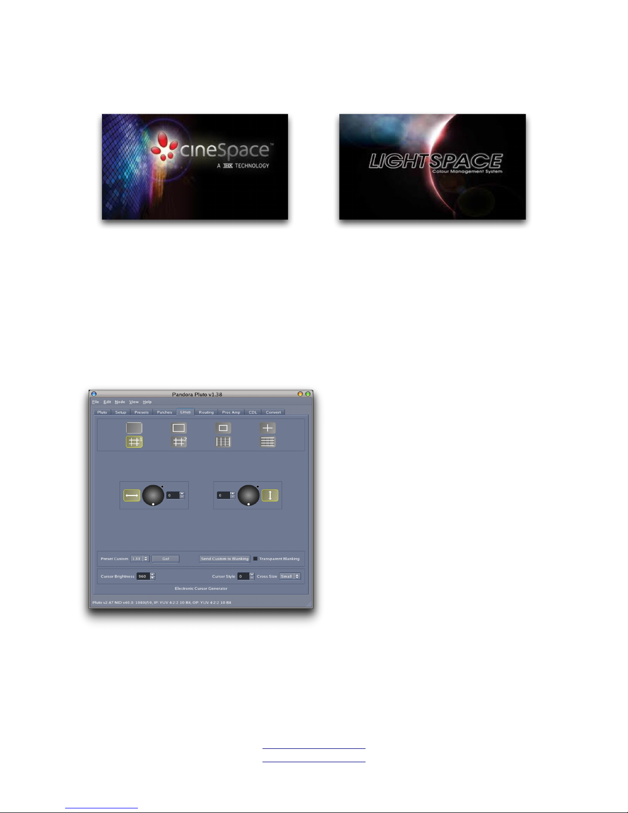
3.9 Linus Tab
For enabling / disabling cage and
cursor overlays.
The cages automatically adjust
according to the input standard.
All cages are applied downstream of
the LUTs.
Pandora Technology sales@pandoratek.org
United Kingdom www.pandora-int.com October 2013
Page 29

Pluto User Manual v1.38 Page 29 of 66
Active picture border
Safe action area [10% within active picture]
Safe title area [20% within active picture]
Central crosshairs
Vertical grid lines. Once selected, use the knobs to set the space
interval.
Horizontal grid lines. Once selected, use the knobs to set the space
interval.
Two user-defined custom areas. With the user-defined area selected,
use the mouse to rotate the horizontal and vertical knobs to adjust the
cage position on the screen. When in use, a readout at the top of the
screen shows the aspect ratio between the horizontal and vertical
markers, and the line and pixel numbers on which they are placed.
When the cross hairs are selected use the Cross size to toggle between small
and full screen.
When the custom areas are selected, Preset Custom can be used to set the area
to various commonly-used ratios such as 1.33, 1.78 and 2.35. Send Custom To
Blanking will match Blanking values to the custom area.
Transparent Blanking is the same as the Transparent switch in the Setup Tab and
shows the picture (in half-level brightness) under the blanking, allowing you to
see the part of the picture being blanked.
The Cursor Style selection changes the cages to combinations of dotted, solid or
yellow lines. Cursor Brightness can be adjusted to eliminate screen burn.
Pandora Technology sales@pandoratek.org
United Kingdom www.pandora-int.com October 2013
Page 30

Pluto User Manual v1.38 Page 30 of 66
3.10 Proc Amp Tab
A simple RGB based Proc Amp is
included in the processing chain. It is
after the LUTs but before the Legaliser.
This is especially useful if installations
require that all such built-in monitor
settings/menus be left at default.
The Sliders allow for fine adjustment
of Black and White points.
Both outputs can be controlled
independently.
Aperture
The Proc Amp tab also features an Aperture control. Use the H & V slider to
adjust levels of Horizontal and Vertical Aperture correction. The black clip allows
control of the edge enhancement in the low luminance areas. Both outputs can
be controlled independently.
Note: The Aperture control function is a special option and is not available in all
versions of Pluto. Please contact Pandora for more information.
Pandora Technology sales@pandoratek.org
United Kingdom www.pandora-int.com October 2013
Page 31

Pluto User Manual v1.38 Page 31 of 66
3.11 CDL Tab
The American Society of
Cinematographers Colour Decision
List (ASC CDL) is a format for the
exchange of basic primary colour
grading information between
equipment and software from
different manufacturers. The Pluto
software can be used to create,
modify or simply load and apply
CDLs.
To load an existing CDL, Ensuring Enable is selected, click Load to browse to
the .cdl or .cdn file and click Open. The CDL is then loaded in to the GUI as a
numerical and graphical representation of the file and applied to the video
signals.
If in Stereo mode, use the Left, Right or Both to apply the look to individual
camera feeds as required.
The CDL is treated as a 1D LUT by the Pluto. If the CDL is to be used in
conjunction with a 3d Cube, use the Input or Output to decide if the CDL should
be applied before or after the cube. For example, if the cube has been created
as a monitor transform LUT and the CDL is an on-set look; for this the CDL
should be Input.
The format defines the maths for three functions: Slope, Offset and Power. Each
function uses a number for the red, green, and blue colour channels for a total of
nine numbers comprising a single colour decision. A tenth number, Saturation,
specified in the Version 1.2 release, applies to the R, G, and B colour channels in
combination.
The functions can be modified in one of four ways; either with a Kensington
trackball, by entering numerical values directly in to the numerical fields, using
the up/down arrows to finely adjust the existing numbers, or using a mouse with
the graphical tracker ball view (see next page).
Pandora Technology sales@pandoratek.org
United Kingdom www.pandora-int.com October 2013
Page 32

Pluto User Manual v1.38 Page 32 of 66
These controls emulate the traditional functions of a Primary colour corrector.
Using a mouse, click and hold over either of the Lift, Gamma or Gain's Master or
Differential controls and drag to adjust the values. The R, G & B values will
update accordingly. The small Reset buttons will clear the change and return the
value to the previously loaded CDL. The first click will clear the Differential, the
second click will clear the Master.
The Clear button at the bottom of the panel will reset all controls to unity.
Once the set look is achieved this can then be saved as a CDL file using the Save
button. in addition to saving, the current look can be loaded directly in to a
Pluto Slot using the Send to Slot button.
The current CDL can be saved and applied to
either the current slot or, using the Slot Number
selector, it can be saved to any other inactive
slot.
Note: This process will over-write the existing
1d LUTs in that slot.
If Available, the Pluto will display RP188 Timecode in this window for both the A
and B channels.
Use the MARK button to log the current CDL data as a Look marked to the
current timecode. Later this can be used to build an ALE or EDL file which allows
the colour information to be used another external system. See the CDL menu
section in Chapter 3 for more information.
A scratchpad is also available, containing 10 positions in which looks can be
Pandora Technology sales@pandoratek.org
United Kingdom www.pandora-int.com October 2013
Page 33

Pluto User Manual v1.38 Page 33 of 66
stored and easily recalled. To store the current look in the scratchpad, hold
down Shift on the keyboard and press one of the numeric keys 1 – 0. To recall a
look from the scratchpad, simply press the numeric key. The look will be
restored into the current LUT (side and input/output), which does not necessarily
need to be the same LUT that was selected when the look was saved.
Pandora Technology sales@pandoratek.org
United Kingdom www.pandora-int.com October 2013
Page 34

Pluto User Manual v1.38 Page 34 of 66
Chapter 4: Front Panel Control
4.1 Overview
Both hardware versions of the Pluto feature an intuitive On Screen Menu system,
overlaid onto the output of SDI Output A.
In this section we give an overview of the menu system and how to navigate
through it. Always bear in mind that most functions can also be carried out
using the software.
There are 2 control knobs on the front panel, each of them is used to access
different menus. Both knobs have 3 actions: (1) Single Press; (2) Press and
Hold; (3) Rotate.
Left Hand Knob
- A single press on this knob will bring up the Main menu and the list of LUT
slots. Select a slot or menu item by turning the knob and then a single click will
apply the LUT's in that slot.
- press & hold will bring up an alternative menu with the list of PRESETS.
Knob will illuminate BLUE when a LUT is applied, otherwise GREEN.
Pandora Technology sales@pandoratek.org
United Kingdom www.pandora-int.com October 2013
Page 35

Pluto User Manual v1.38 Page 35 of 66
Right Hand Knob
- A single press will bring up the CDL setup options and this is really intended
to be used in conjunction with the Tracker ball option on Pluto Rugged.
- press & hold will bring up the Looks menu, which allows you to mark the
current look (CDL settings and slot selected) against the current timecode to
build an ALE or EDL file. It also displays a list of previously marked Looks.
Knob will illuminate BLUE when the CDL is active, otherwise GREEN
4.2 Main Menu (Left hand knob, single press)
Use a single press of the Left knob on the front panel to enable the main LUT onscreen-display (OSD) menu on Output A. The menu will disappear after 10
seconds of inactivity.
Rotate the knob to highlight the desired menu item or LUT Slot, and push the
button to select. Selecting a LUT Slot will apply all 3 LUTS in the slot. The
current slot applied will be highlighted in green.
Pandora Technology sales@pandoratek.org
United Kingdom www.pandora-int.com October 2013
Page 36

Pluto User Manual v1.38 Page 36 of 66
Each line starts with a combination of i, 3 and o to indicate which LUTs are
contained in the slot. If it has a 3D cube, the size of the cube is also shown. e.g.
(3, 17pt) - Indicates the slot has a 3d cube and it has 17 points per side
(i3o, 17pt) - Indicates the slot has an Input 1d, a 3d cube and an Output 1d
LUT; the 3D cube has 17 points per side.
To turn on test patterns, highlight Test and rotate the knob to step through the
15 available patterns. The Pattern will be applied pre-LUT/legaliser to all outputs
at the same standard as the input.
Highlight and select Setup item to navigate into the Setup menu.
Highlight and select Dual Head item to navigate into the Dual Head menu.
4.3 Setup Menu (from Main Menu)
Highlight and select Disable Remote to prevent Software override of current
settings.
Pandora Technology sales@pandoratek.org
United Kingdom www.pandora-int.com October 2013
Page 37

Pluto User Manual v1.38 Page 37 of 66
Highlight and select Disable Front Panel to prevent the control knob from making
accidental changes. When selected, the menu will disappear and can only be
accessed again by press and holding the front panel control knob for 5 seconds.
All current Input and Output settings are highlighted in green. To change these,
navigate to the item and press the knob, then rotate the knob to highlight the
choice and press again, to select.
Col Space - toggles between YUV, RGB, XYZ and Custom. Independent control of
both Input and Output colour spaces allows Pluto to convert from one space to
another.
The Video Mode Selections for the Input and Output allow for the selection of
different colour spaces and Pluto can be used to transcode between these.
Internally (ie through the LUTs the Pluto is always operating in an RGB mode
with at least 14 bit precision. The following modes select the Input or Output
colour transform...
YUV - [Actually YCrCb] is the normal mode of operation for 422 video. Internally
these signals are converted to RGB using either SMPTE REC601 or REC709
depending on video standard.
RGB & XYZ - Technically these standards should only be in a Dual Link or 3G A-
stream mode.
Custom - When this mode is selected, the Matrix values can be entered manually
to suit and colour transform. Go to Node > Properties to enter the values.
The Black and White legalisers can be turned on or off independently by
selecting Legal or Full respectively.
Highlight and select Blanking to navigate into the Blanking Menu.
Highlight and select Network to navigate into the Network Menu.
Highlight and select Date/Time to navigate into the Date/Time Menu.
Highlight and select Clear Memory to navigate into the Clear Memory Menu.
Pandora Technology sales@pandoratek.org
United Kingdom www.pandora-int.com October 2013
Page 38

Pluto User Manual v1.38 Page 38 of 66
4.4 Blanking Menu (from Setup Menu)
Highlight the required side and press to select. Rotate the knob to
increment/decrement the blanking area.
4.5 Network Menu (from Setup Menu)
Use the Network Menu to change the Network parameters of the Pluto. This can
only be done using the front panel control.
Highlight the parameter to change and press to select. Once selected, rotate the
knob to highlight the octet then press to select. Then rotate to increment /
decrement the number. Press again to store the change.
Once completed for all the parameters, select Save and Reboot. The OSD will
become inactive whilst the Pluto reboots.
Pandora Technology sales@pandoratek.org
United Kingdom www.pandora-int.com October 2013
Page 39

Pluto User Manual v1.38 Page 39 of 66
4.6 Date/Time Menu (from Setup Menu)
The date and time are useful when marking Looks, as the current date and time
are stored and displayed with each look (see Look menu). If you don't use this
feature, it is not necessary to set the correct date and time.
Highlight Date and press to select. Rotate to set the correct value for each
component of date, then press to move to the next component. Pressing the
knob after setting the year will take you back to Date and you can then rotate to
Time and set this. This uses a 24 hour clock. Finally highlight and select Save
to Store the date and time in the Pluto. You will need to have a battery installed
to maintain this.
4.7 Clear Memory Menu (from Setup Menu)
Highlight Clear all Look data to clear all previously stored Look data (CDL values
and selected slot) and reset the list. You cannot undo this. You will be prompted
to confirm this action.
Pandora Technology sales@pandoratek.org
United Kingdom www.pandora-int.com October 2013
Page 40

Pluto User Manual v1.38 Page 40 of 66
4.8 Routing Menu (from Main Menu)
Use the Routing Menu to set the routing configuration of the Pluto, and the
stereo options in Stereo mode. See section 3.6 for more details of the possible
routing configurations.
When Routing is set to Dual-Head or Stereo, the Main menu will now include an
additional Side option...
Note that you can now select Side A, B & Both. This selects the desired
processing path (Side or Head) to apply the LUT Slots to.
Using this Method it is possible to apply looks to 2 camera feeds as shown in
Appendix A2.
Pandora Technology sales@pandoratek.org
United Kingdom www.pandora-int.com October 2013
Page 41

Pluto User Manual v1.38 Page 41 of 66
4.9 Presets Menu (Left hand Knob, press-and-hold)
Press and Hold the Left Hand control knob to bring up the Preset Menu.
Rotate the Left Hand Control Knob and click to select the Preset of your choice.
To save the Presets please refer to the Preset Tab section in Chapter 3.
Pandora Technology sales@pandoratek.org
United Kingdom www.pandora-int.com October 2013
Page 42

Pluto User Manual v1.38 Page 42 of 66
4.10 CDL Menu (Right hand knob, single press)
To access the CDL menu, press the right hand control knob once.
Side A, Side B or Both Sides - this setting determines which signal path the
Pluto trackball mouse is going to alter, if it is used. The next chapter describes
how to use the trackball mouse. Note that this does not affect the side that is
controlled from the CDL tab in the GUI (see the CDL tab section in chapter 3).
These options only appear if the Pluto is Dual Head mode is turned on.
INPUT or OUTPUT - this setting determines whether the CDL grade is applied
before or after the 3d Cube in a Slot (when controlling the CDL with the
trackball, not from the CDL tab in the GUI). Also, when the CDL is sent to slot it
will determine whether it is saved in the Input or Output 1d L UT position. Refer
to LUT slot section in Chapter 2 for more information.
Slot - By Default the CDL will be saved into the Input or Output of the current
selected Slot. Use this setting to choose an alternative slot if required.
Send to Slot - click on this to save the current CDL data into the selected slot.
Mark Grade - click on this to save the current CDL data into the Pluto memory
for future download. This is identical to the Mark Look option in the Looks Menu.
Pandora Technology sales@pandoratek.org
United Kingdom www.pandora-int.com October 2013
Page 43

Pluto User Manual v1.38 Page 43 of 66
4.11 Looks Menu (Right hand knob, press-and-hold)
To access the Looks menu, press and hold the Right hand control knob. A Menu
similar to the following will appear on Output A.
Mark Look is initially highlighted, so to mark the current CDL values and slot in
use just press the knob again. The look will be stored and the menu will
disappear. This makes it very easy to mark the current look without having to
navigate through the menus. If you are in dual-head or stereo mode, two look
entries are added, one for side A and one for side B.
This example shows only four stored looks for simplicity (three on side A and one
on side B), but when you open the menu the most recent 10 looks are shown in
the list. The looks are shown in descending order, with the most recent at the
top. The date and time when the look was stored is shown, together with the
video timecode, side A/B, which slot was active at the time (0 will be shown if no
slot was active) and whether or not CDL data was stored on the input and
output. The actual CDL values are not shown.
Page Up and Page Down will show the next/previous ten looks in the list. Use
these buttons to find the looks you are interested in, then rotate to the looks and
press the knob to select them. The look will be highlighted in green when
selected.
If a look is selected, Recall CDL will recall the input and output CDL values into
the current output. This lets you copy a previously stored look and use it again.
If you are in dual-head mode, this option is replaced by two new options: Recall
Pandora Technology sales@pandoratek.org
United Kingdom www.pandora-int.com October 2013
Page 44

Pluto User Manual v1.38 Page 44 of 66
CDL into A and Recall CDL into B.
Only one look should be selected for the Recall CDL function. If you have more
than one look selected no action is taken. Only the CDL values are recalled. The
slot is not loaded.
Note that you do not have to recall the CDL values into the same side that they
were in when the look was stored. In the example menu on the previous page,
the Pluto is in single-head mode and so all looks are recalled to the A side, even
Look number 58, which was stored from the B side. In dual-head mode you can
choose which side to recall into. This makes it very easy to copy a CDL from one
side to the other.
If you have one or more looks selected, Delete Selected will flag all of the
selected looks for deletion. This will stop them from being shown in the list, and
also stop them from appearing in the EDL/ALE files when the Look data is
uploaded to the GUI.
Note that the looks aren't actually deleted. They are only flagged for deletion.
This means that they are not removed from the Look database and, if you keep
marking and deleting, eventually the database will fill up and you won't be able
to mark any more looks. The only two ways to really clear the data are to check
the Clear Data After Upload checkbox in the GUI when uploading the data or
with the Clear All Look Data option in the Clear Memory SubMenu from the Setup
menu of the OSD. It is important that you select one of these options
occasionally when the Look data is no longer needed.
Undo Last Deleted will remove the Deleted flags that were most recently set
from the Delete Selected action. This can only be done immediately after the
deletion to correct a mistake. If you close the menu or mark any more looks you
can no longer undo the last deletion.
Pandora Technology sales@pandoratek.org
United Kingdom www.pandora-int.com October 2013
Page 45

Pluto User Manual v1.38 Page 45 of 66
Chapter 5: Live CDL Control Using a Kensington Trackball
Pandora Technology sales@pandoratek.org
United Kingdom www.pandora-int.com October 2013
Page 46

Pluto User Manual v1.38 Page 46 of 66
The CDL colour look can be set directly on the Pluto off camera, without using
the GUI. The CDL look can then be stored in a slot, or logged for uploading into
an EDL or ALE file. The following steps describe this process.
Step 1: Plug in the Kensington Trackball Mouse into the USB port of the Pluto.
Step 2: Press the
Left Hand mouse button
Left Hand mouse button. In the Top left hand corner of the SDI
output A, the current status of the CDL control is shown. By Default the status is
"CDL is Off".
Step 3: Press and hold the
Left Hand mouse button
Left Hand mouse button, until the status changes. A
single press of the left button will then toggle through the following controls.
The Trackball gives colour differential control and the Control Ring gives a master
level control for the following:
Lift - Colour and level control in the low lights.
Gamma - Colour and gamma curve control
Gain - Colour and level control in the highlights
Saturation - The control ring controls Chroma saturation (trackball not used).
Pandora Technology sales@pandoratek.org
United Kingdom www.pandora-int.com October 2013
Page 47

Pluto User Manual v1.38 Page 47 of 66
Step 4: Use the
Right Hand mouse button
Right Hand mouse button to
Reset
Reset the previous changes made.
A single press resets the colour differential; a double press resets the master
level control as well.
Step 5: Store the CDL information as a Look. Press and hold the Right hand
control Knob on the Pluto to bring up the Look menu, then select Mark Look.
"Stored current Look" is displayed on the SDI output. The CDL values, slot
number, current time/date and the associated Timecode (decoded from the input
SDI stream) are saved for later download.
Note: the original CDL specifications allow for Power, Slope and Offset. Pluto
applies a matrix internally to allow the operator to work in Lift, Gamma, Gain to
give the "feel" of a traditional primary colour corrector. When the current grade
is saved, the resulting CDL data is calculated and saved as Power, Slope and
Offset to comply with the ASC's specification.
Step 6: Download the CDL data. When the Pluto is next connected via ethernet
to the software control app, click on the Pluto in the Left Hand Pane (see Chapter
2 for details). If there is previously unsaved CDL data in the Pluto Memory the
following Pop Up Window will appear.
Click to choose if the data should be cleared after
download, then click OK to download the data. A
new popup will appear, shown below.
Select an output directory and whether you wish to
create ALE files and/or EDL files, then press OK.
Separate files are created for each date that
has data stored (make sure the date is
correctly set on the Pluto, through the Setup
menu), as well as for each video standard that
was feeding the Pluto at the time. Along with
CDL values, the names of any 3D LUT in use is
also added as a comment. The actual 3D data
is not stored.
Step 7: An alternative to saving the CDL data as an ALE is to directly store the
current grade into a slot of the Pluto. Use the Right hand control Knob on the
front panel to bring up the CDL Menu, as described in the next section.
Pandora Technology sales@pandoratek.org
United Kingdom www.pandora-int.com October 2013
Page 48

Pluto User Manual v1.38 Page 48 of 66
Chapter 6: Licensing
The Pluto is capable of running all the applications described in this manual
simultaneously, provided they are licensed. The following require a license:
• LUT management
• Stereoscopic Processing
• Cursor Generator
• CDL functions
• Aperture controls
The scope of this manual is to provide detailed information on how to use each
of these applications. For further information of what functionality is included
within each License please download the Pluto Data Sheet from the Products
section of the Pandora website or contact sales@pandoratek.org
To view the current license information, do the following:
• Click on the required Pluto in the left hand Pane.
• In the menus, click on Node
• Click on License Info
This window shows the currently selected
Pluto(s) and related license information.
Multiple units can be selected and all of them
will appear in the pull-down list. These follow
the “Upload” radio buttons in the main Pluto
tab. If the upload type is set to “Single” then
only the single selected Pluto will appear in the
license window (with the exception of 4K
units). If the upload type is set to “Group” or
“All”, then the list will contain all Plutos in the
same group, or all Plutos on the network.
Note that 4K units physically consist of two
standard Plutos (usually in the same unit) and
so this list will always contain at least two
Plutos if a 4K unit is selected.
The node information at the top (Pluto name, IP, serial number and current
timestamp) is then followed by the details of all licenses currently on this unit.
Pandora Technology sales@pandoratek.org
United Kingdom www.pandora-int.com October 2013
Page 49

Pluto User Manual v1.38 Page 49 of 66
To request an additional license for all of the Plutos listed in this
window, do the following:
• Click on Create Request
• Save the xx.plr file to the desktop
• Email the xx.plr file to service@pandoratek.org detailing the requirements.
It woud be very helpful to include the serial numbers of the units (shown in
the license window) with the request, especially if you are requesting
licenses for more than one unit.
• Upon receipt of the newlicence.pll file, save it to the desktop.
• Click on Upload License. This will check that the license file is intended for
the currently selected units and upload the each new license in the file to
the appropriate Pluto.
Pandora Technology sales@pandoratek.org
United Kingdom www.pandora-int.com October 2013
Page 50

Pluto User Manual v1.38 Page 50 of 66
Chapter 7: Firmware
The Pluto requires firmware to operate, which is loaded automatically from flash
memory when powered on. Pluto does not require the software control interface
to operate, enabling it to be pre-loaded with LUTs and used on-set.
Pluto Version 1.16 and upwards is a complete package of Software and
compatible Firmware that features a self-check mechanism to ensure the correct
versions are currently loaded.
When a Pluto is selected from the GUI, the following pop-up will appear if the
firmware is not the current version:
If that is the case, simply select Update. A dialog will then appear asking you to
enter the security PIN. This is a simple level of protection to stop users from
switching firmware accidentally (for example, when trying an older version of the
GUI) and allows you to control who can do the update. The PIN defaults to
1111 but can be changed through the Edit->Preferences menu on the GUI. The
old PIN is not required to set a new one. Note that the PIN is stored for each
GUI, not for each Pluto.
After entering the PIN and pressing OK, the firmware will be loaded and the Pluto
will automatically reboot.
In order to manually check the Pluto is up to date, take the following steps:
• First download the latest version of the Pluto Control app from the web
page www.pandora-int.com/support.php
• Run the Pluto app and click on the Pluto you wish to check in the left hand
pane.
• Select Node from the Upper menu, then select Firmware.
Pandora Technology sales@pandoratek.org
United Kingdom www.pandora-int.com October 2013
Page 51

Pluto User Manual v1.38 Page 51 of 66
• One of the following pop-up windows will appear:
• If everything is Up-to-date, close the window.
• If either of the firmware is showing in Red as requiring an Update, then
click on Update.
• The firmware is downloaded into the flash memory.
• The Pluto will automatically reboot.
The Pluto has 2 firmware memories internally, which are identical when shipped.
The 1st bank cannot be changed and is a 'Factory" back-up. If the updated
firmware is corrupted for whatever reason, or the process fails, the Pluto will
automatically use the Factory version. The update process can then be reattempted.
Note: The Factory firmware can be manually recalled by holding in the control
knob whilst powering up.
Pandora Technology sales@pandoratek.org
United Kingdom www.pandora-int.com October 2013
Page 52

Pluto User Manual v1.38 Page 52 of 66
Appendix A1: Example of using a Pluto in Dual Head mode in a
Post Production environment.
In this example Suite B is using the Pluto to apply a constant 3d cube and a
legaliser to the output of the router on to the monitor in the room. Meanwhile
Suite A is using the Pluto to do patch generation for monitor profiling whilst
applying, or bypassing, a 3d cube.
In each Suite the Mac-mini (it could be any PC) is running the Pluto App to
control only their side of the Pluto chassis, which is located in a central apparatus
room, over the house network.
Pandora Technology sales@pandoratek.org
United Kingdom www.pandora-int.com October 2013
Page 53

Pluto User Manual v1.38 Page 53 of 66
Appendix A2: Example of using a Pluto in Dual Head mode in an
On-Set environment.
In this example the Pluto is use in Dual head mode whilst On-Set. Head A is
being used to apply a 3d Cube to Camera A feed, whilst Head B is being used to
apply a CDL on the fly, using the trackball mouse, to Camera B.
By doing this, it is possible to colour balance 2 cameras using just 1 Pluto.
Pandora Technology sales@pandoratek.org
United Kingdom www.pandora-int.com October 2013
Page 54

Pluto User Manual v1.38 Page 54 of 66
Appendix B: THX CineSpace workflow and set up
The Pluto can be used as part of a closed loop monitor profiling set up, utilising
THX's CineSpace software suite. With Pandora's Pluto Plug-in installed, the Pluto
forms a hardware partnership with the CineProfiler software.
The Pluto will automatically generate the patches as commanded by CineProfiler
and collect data from the Probe simultaneously to build a profile.
To enable this functionality, first download the Plug-In from the Support area of
the Pandora Website.
www.pandora-int.com/support
On the workstation where CineSpace is
installed, navigate to the plugins
directory within the CineSpace
installation directory. Copy the
PlutoPlugin.dll into this location.
On the next Launch of CineProfiler the
Pluto Calibration Plugin should be
displayed in the plugin area.
The Pluto software control app is not
required at any point, but ensure all
LUTs are enabled/disabled as required
before commencing profiling.
Pandora Technology sales@pandoratek.org
United Kingdom www.pandora-int.com October 2013
Page 55

Pluto User Manual v1.38 Page 55 of 66
Click on the Pluto Calibration check box to bring up the Pluto Plugin parameter
box.
IP Address – enter the IP address of
the Pluto required to generate patches.
Black and White – Set the black and
white points in terms of 10bit
numbering in accordance with the
monitors capabilities. Generally Black
will be 0 or 64, White will be 1023 or
940. Luminance values of the Patches
will be scaled between these 2 values.
Patch Size – Used to generate less than full screen patches. Particularly useful
on Plasma's where luminance values can vary widely depending on screen size.
Screensaver – Pluto will automatically send Black to the monitor if it does not
receive a command to send another patch within the given period period in
seconds. This useful feature will protect the screen from Burn-ins in the event of
OS crash during profiling, or can enable the engineer to leave the profile
unattended overnight. If set to 0 the feature is disabled.
Once profiling commences, several things happen automatically to the Pluto:
1) Local (front panel) and remote (software) control are locked out. This is done
to prevent accidental interference of the procedure.
2) Black and White Legalisers are turned off
3) Linus Cages are turned off
4) Patches are generated in accordance with the size set in CineProfiler plugin
and sent to all outputs.
To regain control of the Pluto, CineProfiler must be closed. Once closed, the Pluto
resumes its original state and settings.
Note: if the Pluto is in Dual-head mode, profiling can only be carried out using
head A.
Pandora Technology sales@pandoratek.org
United Kingdom www.pandora-int.com October 2013
Page 56

Pluto User Manual v1.38 Page 56 of 66
Figure B1: Schematic of Pluto/CineSpace profiling set up.
Pandora Technology sales@pandoratek.org
United Kingdom www.pandora-int.com October 2013
Page 57

Pluto User Manual v1.38 Page 57 of 66
Appendix C: Light Illusion's LightSpace workflow and set up
The Pluto can be used as part of a closed loop monitor profiling set up, utilising
Light Illusion's LightSpace software suite. The Pluto will automatically generate
the patches as commanded by LightSpace and collect data from the Probe
simultaneously to build a profile.
To enable this functionality, open a Pluto software control app and click on the
Patches Tab.
Click in the Listen to server check box to allow the Pluto to communicate with
LightSpace for automatic patch generation. This will pop up a window for IP
details. Enter the IP address of the workstation running LightSpace.
Leave the Pluto Software open for the duration of the profiling process as
LightSpace communicates with the Pluto via this app.
Hint: For greater ease of use, run the Pluto Software on the same workstation as
the LightSpace
In LightSpace, open the Network settings and check the IP address of the
workstation running Pluto software is being displayed. Refer to LightSpace
manual for further information.
Note: that when Listen to server is selected, test pattern 16 will automatically be
selected to avoid confusion. It is possible to select Disable Front panel and
Disable Remote Access during the profiling process as a way to ensure to there
is no external interference during this sometimes lengthy process. Remember to
Bypass all LUTS if required before starting the process.
Pandora Technology sales@pandoratek.org
United Kingdom www.pandora-int.com October 2013
Page 58

Pluto User Manual v1.38 Page 58 of 66
Figure C1: Schematic of Pluto/LightSpace profiling set up
Pandora Technology sales@pandoratek.org
United Kingdom www.pandora-int.com October 2013
Page 59

Pluto User Manual v1.38 Page 59 of 66
Appendix D: Setting up a Pluto in 4K mode
The Pluto has been tested with the Sony F55 4K camera and 4K OLED display.
Pandora recommends connecting the F55 to the OLED Monitor directly at first.
When the Camera is correctly set up to produce a 4K image then the Pluto can
be inserted.
The Four SDI Channels on both the OLED Monitor and the Camera are labelled 1
to 4 and correspond to the following sections of the 4K display:
CHANNEL ONE must be present as the monitor uses this as a timing reference. If not present NO OUTPUT.
Other channels can be removed and the remaining part of the image stays on the screen.
Pandora Technology sales@pandoratek.org
United Kingdom www.pandora-int.com October 2013
Page 60

Pluto User Manual v1.38 Page 60 of 66
The Connections to Pluto are attached as Follows:
F55 Camera Configuration
To Change Video Frame Rate, Choose the SYSTEM menu and set FREQUENCY.
To Change Video Output Mode, Choose VIDEO menu and select SDI Mode, then
set to 4096 x 2160 XADV
Camera must also be set to YUV Output mode [4K not possible in RGB Mode]
Pandora Technology sales@pandoratek.org
United Kingdom www.pandora-int.com October 2013
Page 61

Pluto User Manual v1.38 Page 61 of 66
Setting up 4K Pluto from the GUI:
• Make sure Pluto firmware is up-to-date (The GUI contains the latest
firmware and will warn you if it's not uploaded – do not ignore this
warning!)
• Both board must be connected to ethernet as well as the PC used for
control and setup. An ethernet hub or switch will be required.
• Setup the IP addresses on the two boards so that they are different and
note the IP of the board that is to be the master and the board that is to
be the slave. If you have a 2-board 4K unit supplied as a single rack, the
master will be the board on the left (when viewed from the front) next to
the front panel control knobs. See the notes on IP addresses below.
• Go to the “Routing” tab and set configuration to “4K”.
• In the “Slave IP Address” box, enter the IP of the second Pluto board (the
one on the right). MAKE SURE THAT YOU DON’T TYPE IN THE IP
ADDRESS OF THE MASTER BOARD (or else it will talk to itself!)
• When you switch to the “Pluto” tab, the two Pluto boards shown in the
Node’s window should become one and will be displayed with a 4K icon.
There are two things happening now:
• firstly both boards are automatically set to Dual Head mode so that there
are four active streams of video.
• All commands sent to the first board from the GUI or from the Front panel
knob get passed to both boards so that e.g. the same LUTs or CDLs are
loaded in all four channels. When uploading LUTs, they will be
automatically uploaded to both boards with the same slot position.
If required (for debug purposes) you can see both boards of the 4K Pluto
individually in the GUI. To do this, open the EDIT->PREFERENCES menu and
select “Show 4K Slaves”.
Pluto will remember the mode that it is set to, so if you configure for 4K
operation and switch off when the unit is powered up again it will [after booting]
reconfigure to 4K mode with the two boards linked together.
The communication between the two boards is via ethernet so you MUST have
both boards plugged into an ethernet hub or switch.
Pandora Technology sales@pandoratek.org
United Kingdom www.pandora-int.com October 2013
Page 62

Pluto User Manual v1.38 Page 62 of 66
It is possible to operate pluto in the 4k mode without using a computer.
In this case the two ethernet ports on the rear of the Pluto must be connected
together using an ethernet crossover cable.
Compatible functions:
The following Items have now been tested together with Sony F55 Camera and 4K OLED Display:
F55 Camera Video Modes
4096 x 2160 Output. All Video Modes Supported.
24P / 25P / 29.97P / 50P / 59.97P
Note that this camera produces four streams of HD Video at 2048 x 1080 lines.
24/25/29.97 are True Progressive Standards at 1.485GHz
50 / 59.97 are PsF using 3G-SDI Signalling.
4K OLED Display
It is necessary to manually switch between 1.485GHz and 3G Input Modes.
Tested Pluto Functions
• 4096 x 2160 [4K DCI] Video Inputs in 1.485 and 3G SDI Standards
• 3840 x 2160 [Quad HD] Video Inputs
• Frame Rates ….
23.98/24/25/29.97/30 PROGRESSIVE Standards
47.96/48/50/59.94/60 INTERLACED or PsF Standards
We do not currently support 50 / 60 Progressive standards using 3G-SDI Level A Signalling.
(For the F55 Camera when switched to 50P operation, output is in fact 50PsF so we
support all possibilities for this camera).
• 444/422 Operation is supported in All standards.
• YUV/RGB or XYZ Modes in All standards.
• 1D LUTs
• 3D LUTs all supported standards up to 33 nodes.
Note that when set to 4K Operation the front panel knob on Pluto will correctly select LUTs on both
boards. An ethernet connection is required for this to work so please see installation details.
• ASC CDL & Saturation
Tested in full 4K mode from Pandora GUI and PomFort LiveGrade.
• VIDEO LEGALISER: black / white / custom
Not Yet Supported On Pluto (but coming soon)
• VIDEO BLANKING … Note that this is not disabled in the current software but it will not
produce correct results for now make sure Blanking is set to full frame.
• TEST PATTERN GENERATOR:
Pandora Technology sales@pandoratek.org
United Kingdom www.pandora-int.com October 2013
Page 63

Pluto User Manual v1.38 Page 63 of 66
For the moment Test Patterns are produced in two quadrants of the 4K display only.
We will alter the software to produce Full Frame 4K Test patterns soon.
False Colour Display is working OK in 4K Display Modes.
Pandora Technology sales@pandoratek.org
United Kingdom www.pandora-int.com October 2013
Page 64

Pluto User Manual v1.38 Page 64 of 66
Appendix E: Keyboard Shortcuts (Hotkeys)
Key Tab Description
Left arrow All Previous tab
Right arrow All Next tab
Up arrow Pluto Select previous node
Down arrow Pluto Select next node
1 – 0 Pluto Load slot 1 – 10
Shift + (1 – 0) Pluto Load slot 11 – 16
1 – 5 Presets Load preset 1 – 5
Shift + (1 – 5) Presets Save preset 1 – 5
1 – 0 CDL Load scratchpad look 1 – 10
Shift + (1 – 0) CDL Save scratchpad look 1 – 10
m CDL Mark grade
a CDL Select side A (also on Pluto)
b CDL Select side B (also on Pluto)
c CDL Select both sides (also on Pluto)
Pandora Technology sales@pandoratek.org
United Kingdom www.pandora-int.com October 2013
Page 65

Pluto User Manual v1.38 Page 65 of 66
Appendix F: Specification
SDI Video Inputs and Outputs
Physical
Sampling
Colour Space
SD Formats
HD Formats
HD 3G
SDI Audio
SD Compliance
HD Compliance
Timecode Compliance
2 x BNCin + 2 x BNCout 270MHz/1.484GHz/2.997GHz
4:2:2/4:4:4 – 8/10 Bit [16bit internal processing]
Y:U:V/ R:G:B / X:Y:Z
625/25, 525/29.97
720x1280 @23.98p, 24p, 25p, 29.97p, 30p, 50p, 60p
1080x1920 @ 23.98psf, 24psf, 50i, 59.94, 60i
1080x2048 @ 23.98psf, 24psf, 50i, 59.94i, 60i
B stream mode only [dual link on single cable]
Note: Pluto can convert from 3G input to dual stream 1.5G output if
required.
Embedded 8 channels @ 48khz, 24bit, passed through to outputs
ITU-656, ITU-601
SMPTE 274M, SMPTE 296M, SMPTE 352M
SMPTE RP188 Decoded and passed through to outputs
Physical
1U Chassis
Power
Cooling
Dimensions
Rugged Chassis
Power
Cooling
Dimensions
1U Rackmountable or
85-264VAC 50-60HZ 0.22A Max at 240V
No Fan, Ensure top vents are clear
W: 430mm, D: 220mm, H: 44mm
Rugged Aluminium Extruded Chassis
85-264VAC, 50-60HZ 0.22A Max at 240V
Heatsink via chassis only.
W: 173mm, D: 253mm, H: 56mm
LUTs
1D
ASC CDL support
3D
.mga (Pandora MegaGamma), .lut (Autodesk)
1D LUTs up to 1024 points x 16-bit RGB
Yes. CDL, CDN loaded as Input or Output 1D LUTs
.m3d (Pandora) .3dl (Kodak, BlackMagic, Autodesk), .dat (DaVinci),
.cms (Nucoda), .itx (Iridas), .cub (Truelight), .lut (Autodesk)
3D Cubes may be 16, 17, 32, 33 points and use 16-bit internal
architecture
Linus
Title Safe Cage
Action Safe Cage
90% Marker. HD width is pixel 95-1824, SD width is pixel 35-685
80% Maker. HD width is pixel 192-1728, SD width is pixel 71-650
Software
Pluto Management software
Supported Profiling software
Mac OSX 10.5-10.8, Windows XP/Vista/7, Linux Red Hat Ent 4
Lightspace CMS by Light Illusion
CineProfiler by THX
Pandora Technology sales@pandoratek.org
United Kingdom www.pandora-int.com October 2013
Page 66

Pluto User Manual v1.38 Page 66 of 66
Pandora Technology sales@pandoratek.org
United Kingdom www.pandora-int.com October 2013
 Loading...