

Page 1
Operating Instructions
WV-X8570N
Network Camera
Model No. WV-X8570N
WV-S8530N
Before attempting to connect or operate this product, please read these instructions
carefully and save this manual for future use.
The model number is abbreviated in some descriptions in this manual.
Page 2

X8570N
S8530N
Preface
Preface
About the user manuals
There are 3 sets of operating instructions as follows.
• Operating Instructions (this document): Explains how to perform the settings and how to operate this
camera.
• Important Information: Provides information about the cautions required for safely using and installing this
camera.
• Installation Guide: Explains how to install and connect devices.
The screens used in these operating instructions show the case of WV-X8570N. Depending on the model
used, the screens shown in the explanations may differ to the actual camera screens.
Note
• “Control No.:C****” used in this document should be used to search for information on the Panasonic
support website and will guide you to the right information.
About notations
The following notations are used when describing the functions limited for specified models.
The functions without the notations are supported by all models.
: The functions with this notation are available when using the model WV-X8570N.
: The functions with this notation are available when using the model WV-S8530N.
Abbreviations
The following abbreviations are used in these operating instructions.
Microsoft Windows 10 is described as Windows 10.
Microsoft Windows 8.1 is described as Windows 8.1.
Microsoft Windows 7 is described as Windows 7.
Windows Internet Explorer 11 is described as Internet Explorer.
SDXC/SDHC/SD memory card is described as SD card or SD memory card.
Universal Plug and Play is described as UPnP™ or UPnP.
For administrator registration
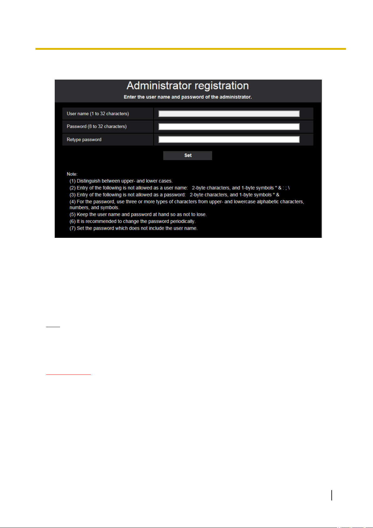
At the time of first access to the camera (or at the time of initialization), the registration screen will be displayed.
2 Operating Instructions
Page 3
Preface
Define the user name and the password for the administrator, and enter them correctly. Hereafter, they can
be used for login.
[User name (1 to 32 characters)]
Enter the user name of the administrator.
Available number of characters: 1 - 32 characters
Unavailable characters: 2-byte characters, and 1-byte symbols " & : ; \
[Password (8 to 32 characters)]/[Retype password]
Enter the administrator password.
Available number of characters: 8 - 32 characters
Unavailable characters: 2-byte characters, and 1-byte symbols " &
Note
• Distinguish between upper- and lower cases.
• For the password, use three or more types of characters from upper- and lowercase alphabetic
characters, numeric characters, and symbols.
• Set the password which does not include the user name.
IMPORTANT
• If you forgot or do not know the password or user name, the camera must be initialized. Because all
settings other than preset position settings are deleted when the camera is initialized, make sure to
keep the information secure from third parties. Refer to “Parts and functions” section in the Important
Information in the supplied CD-ROM for more information about initializing the camera.
• It is recommended to change the password periodically.
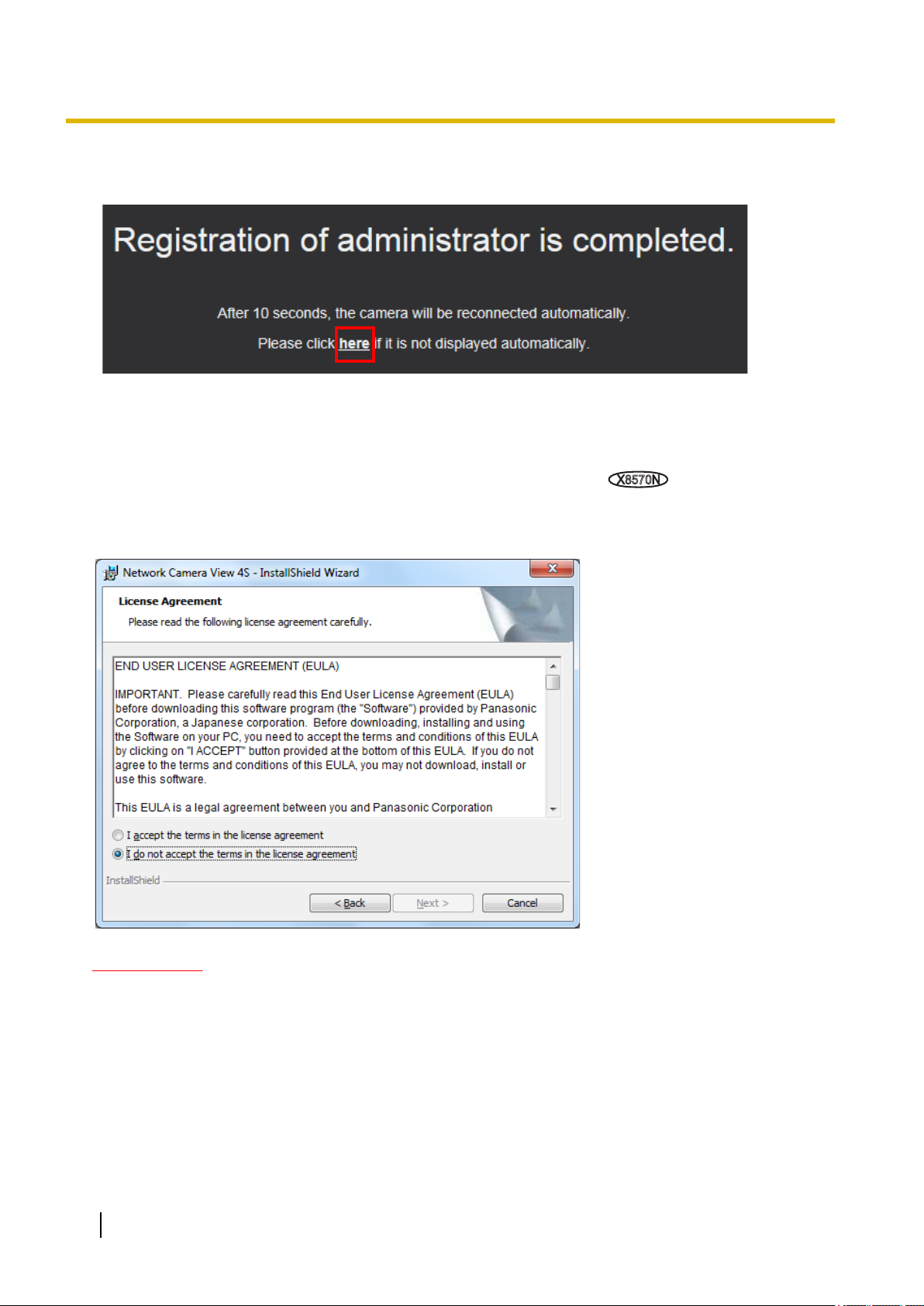
The registration completion screen will be displayed after registering a user name and password of the
administrator. After 10 seconds, the camera will be reconnected automatically. Please click “here” if it is not
displayed automatically.
Operating Instructions 3
Page 4
X8570N
Preface
When the camera is reconnected to, an authentication window is displayed. Enter the registered user name
and password to start operation.
Viewer software
In order to display H.265 (or H.264) images, receive audio from the camera
on the SD memory card, the “Network Camera View 4S” (ActiveX®) viewer software must be installed. This
software can be installed directly from the camera or by selecting the [Install] button next to [Viewer
Software] on the menu of the CD-ROM provided, and then following the on-screen instructions.
, and play images saved
IMPORTANT
• The default setting of “Automatic installation” is “On”. Follow the instructions on page 209 when the
message is displayed on the information bar of the browser.
• Depending on the software environment of your PC, it may take time for the message to be displayed
on the information bar of the browser.
• If you display the “Live” page on a PC and click the [Viewer Software] button, the installation screen
for ActiveX, which is required for viewing camera images, is displayed. Follow the on-screen
instructions and install the software. When displayed JPEG images (still images), there is no need to
install ActiveX.
• When the install wizard is displayed again even after completing the installation of the ActiveX, restart
the PC.
4 Operating Instructions
Page 5

Preface
• The viewer software used on each PC should be licensed individually. The number of installations of
the viewer software from the camera can be checked on the [Upgrade] tab of the “Maintenance” page
(®page 183). Refer to your dealer for the software licensing.
Operating Instructions 5
Page 6

X8570N
X8570N
X8570N
X8570N
S8530N
S8530N
Table of Contents
Table of Contents
1 Operations ................................................................................................9
1.1 Monitor images on a PC ...................................................................................................9
1.1.1 Monitor camera images ....................................................................................................9
1.1.2 About the “Live” page .....................................................................................................12
1.2 Monitor images on a mobile terminal or tablet device ................................................16
1.2.1 Monitor images on a mobile terminal (including smartphones) ......................................16
1.2.2 Monitor images on a tablet device ..................................................................................20
1.3 Record images on the SD memory card manually ......................................................24
1.4 Action at an alarm occurrence .......................................................................................26
1.4.1 Alarm type ......................................................................................................................26
1.4.2 Action at an alarm occurrence ........................................................................................26
1.5 Display the log list ..........................................................................................................28
1.6 Playback of images on the SD memory card ...............................................................32
1.6.1 Playback “Stream(1)”/“Stream(2)” images saved to the SD memory card .....................33
2 Settings ...................................................................................................36
2.1 About the network security ............................................................................................36
2.1.1 Equipped security functions ...........................................................................................36
2.2 Display the setup menu from a PC ................................................................................37
2.2.1 How to display the setup menu ......................................................................................37
2.2.2 How to operate the setup menu .....................................................................................38
2.2.3 About the setup menu window .......................................................................................39
2.3 Use Easy Setup [Easy Setup] ........................................................................................41
2.3.1 Configure Easy installation [Easy installation] ................................................................41
2.3.2 Configure the Internet settings [Internet] ........................................................................42
2.3.3 Configure an event action [Event action] ........................................................................44
2.3.3.1 Configure the schedule/alarm (event function type setup menu) ................................45
2.3.3.2
2.3.3.3 Alarm: Sets the recording stream (recording stream setup menu). .............................48
2.3.3.4 Alarm: Configure the details for recording conditions ..................................................49
2.3.3.5
2.3.3.6 Alarm: configure the mail notifications and mail server ...............................................50
2.3.3.7 Schedule: Configure SD recording (Recording format setup menu) ...........................52
2.3.3.8 Schedule: Set SD memory recording (video recording setup menu) ..........................52
2.4 Configure the basic settings of the camera [Basic] ....................................................55
2.4.1 Configure the basic settings [Basic] ...............................................................................55
2.4.2 Configure the settings relating to the SD memory card [SD memory card] ....................62
2.4.3 Configure the settings relating to alteration detection [Alteration detection] ..................68
2.4.4 How to configure alteration detection settings ................................................................70
2.4.4.1 Generation of the CRT key (encryption key) ...............................................................70
2.4.4.2 Generation of CSR (Certificate Signing Request) .......................................................71
2.4.4.3 Installation of the certificate issued by CA ...................................................................73
2.4.4.4 Configuration of alteration detection ............................................................................74
2.4.5 Access copy images saved on the SD memory card onto the PC [SD memory card
2.4.6 Configure the directory of the PC that images will be downloaded to [Log] ...................76
2.5
2.5.1
2.5.2 Configure the settings relating to JPEG images [Image] ................................................78
2.5.3 Configure the settings relating to Stream [Image] ..........................................................80
Alarm: Configure the terminal
Alarm: Configure the output terminal
and VMD (alarm setup menu) ........................46
.............................................................50
images] ...........................................................................................................................75
Configure the settings relating to images and audio
Image
] .................................................................................................................77
Configure the settings relating to the image capture mode [Image]
[Image/Audio
..................77
,
6 Operating Instructions
Page 7

X8570N
X8570N
X8570N
Table of Contents
2.5.4 Configure the settings relating to image adjust, privacy zone, and VIQS [Image
quality] ............................................................................................................................87
2.5.4.1 Configure the settings relating to image quality (“Image adjust” setup menu) ............87
2.5.4.2 Set mask areas ............................................................................................................97
2.5.4.3 Configure the settings relating to the privacy zone (“Privacy zone” setup
menu) ........................................................................................................................100
2.5.4.4 Configure the VIQS setting ........................................................................................102
2.5.4.5 Configure the VIQS area ...........................................................................................104
2.5.5
Configure the settings relating to audio [Audio]
..............................................106
2.6 Configure the alarm settings [Alarm] ..........................................................................108
2.6.1 Configure the settings relating to the alarm action [Alarm] ...........................................108
2.6.2
2.6.3
Configure the settings relating to the output terminal [Alarm]
Change the AUX name [Alarm]
......................................................................112
........................110
2.6.4 Configure the settings relating to the camera action on alarm occurrence
[Alarm] ..........................................................................................................................113
2.6.4.1 Configure settings relating to alarm E-mail notifications ............................................114
2.6.4.2 Configure settings relating to recording to an SD memory card when an alarm
occurs ........................................................................................................................115
2.6.4.3 Configure settings relating to Panasonic alarm protocol notification when an alarm
occurs ........................................................................................................................116
2.6.4.4 Configure settings relating to HTTP alarm notification when an alarm occurs ..........117
2.6.5 Configure the VMD settings [VMD area] ......................................................................117
2.6.6 Set the VMD areas [VMD area] ....................................................................................119
2.6.7 Configuration of the settings relating to alarm notification [Notification] .......................121
2.6.7.1 Configure the settings relating to Panasonic alarm protocol .....................................122
2.6.7.2 Configure the settings relating to HTTP alarm notification ........................................124
2.7 Configure the settings relating to the authentication [User mng.] ...........................126
2.7.1 Configure the settings relating to the user authentication [User auth.] .........................126
2.7.2 Configure the settings relating to the host authentication [Host auth.] .........................129
2.7.3 Configure the settings relating to the priority stream [System] .....................................130
2.7.4 Configure IEEE 802.1X [IEEE 802.1X] .........................................................................131
2.7.5 Configure the data encryption settings [Data encryption] .............................................132
2.8 Configuring the network settings [Network] ..............................................................134
2.8.1 Configure the network settings [Network] .....................................................................134
2.8.2 Configure advanced network settings [Advanced] .......................................................138
2.8.2.1 Configure the settings related to sending E-mails .....................................................139
2.8.2.2 Configure the settings relating to the NTP server ......................................................143
2.8.2.3 Configure the UPnP settings .....................................................................................144
2.8.2.4 Configure the HTTPS settings ...................................................................................146
2.8.2.5 Configure the settings relating to DDNS ....................................................................147
2.8.2.6 Configure the settings relating to SNMP ...................................................................149
2.8.2.7 Configure the QoS settings .......................................................................................150
2.8.3 How to configure HTTPS settings ................................................................................152
2.8.3.1 Select the certificate to use when accessing with HTTPS .........................................153
2.8.3.2 Obtaining the root certificate ......................................................................................153
2.8.3.3 Configuration of HTTPS connections ........................................................................159
2.8.3.4 Generation of the CRT key (SSL encryption key) .....................................................160
2.8.3.5 Generation of CSR (Certificate Signing Request) .....................................................161
2.8.3.6 Installation of the CA certificate .................................................................................162
2.8.4 Access the camera using the HTTPS protocol (for pre-installed certificate) ................163
2.8.4.1 Configuration of the host file ......................................................................................163
2.8.5 Access the camera using the HTTPS protocol (for CA Certification) ...........................168
2.8.6 How to configure the settings relating to DDNS ...........................................................169
Operating Instructions 7
Page 8

Table of Contents
2.8.6.1 Configuration of the DDNS service (Example of the “Viewnetcam.com”
service) ......................................................................................................................170
2.8.6.2 When using “Dynamic DNS Update” .........................................................................173
2.8.6.3 When using “Dynamic DNS Update(DHCP)” ............................................................174
2.9 Configure the settings relating to the schedules [Schedule] ...................................175
2.9.1 How to set the schedules .............................................................................................178
2.9.2 How to delete the set schedule ....................................................................................180
2.10 Maintenance of the camera [Maintenance] .................................................................182
2.10.1 Check the system log [System log] ..............................................................................182
2.10.2 Upgrade the firmware [Upgrade] ..................................................................................183
2.10.3 Check the status [Status] .............................................................................................184
2.10.4 Reset the settings/Reboot the camera [Default reset] ..................................................187
2.10.5 Settings data/backing up or restoring logs [Data] .........................................................188
2.11 Display the Panasonic support website [Support] ....................................................190
3 Others ....................................................................................................191
3.1 Using the CD-ROM ........................................................................................................191
3.1.1 About the CD launcher .................................................................................................191
3.1.2 Installing Panasonic “IP Setting Software” ...................................................................192
3.1.3 Installing the manuals ...................................................................................................193
3.1.4 Installing the Viewer software .......................................................................................193
3.1.5 Configure the network settings of the camera using the Panasonic “IP Setting
Software” ......................................................................................................................194
3.2 About the displayed system log ..................................................................................197
3.3 Troubleshooting ............................................................................................................201
3.4 Directory structure of drive B ......................................................................................211
8 Operating Instructions
Page 9
1 Operations
1.1 Monitor images on a PC
The following are descriptions of how to monitor images from the camera on a PC.
1.1.1 Monitor camera images
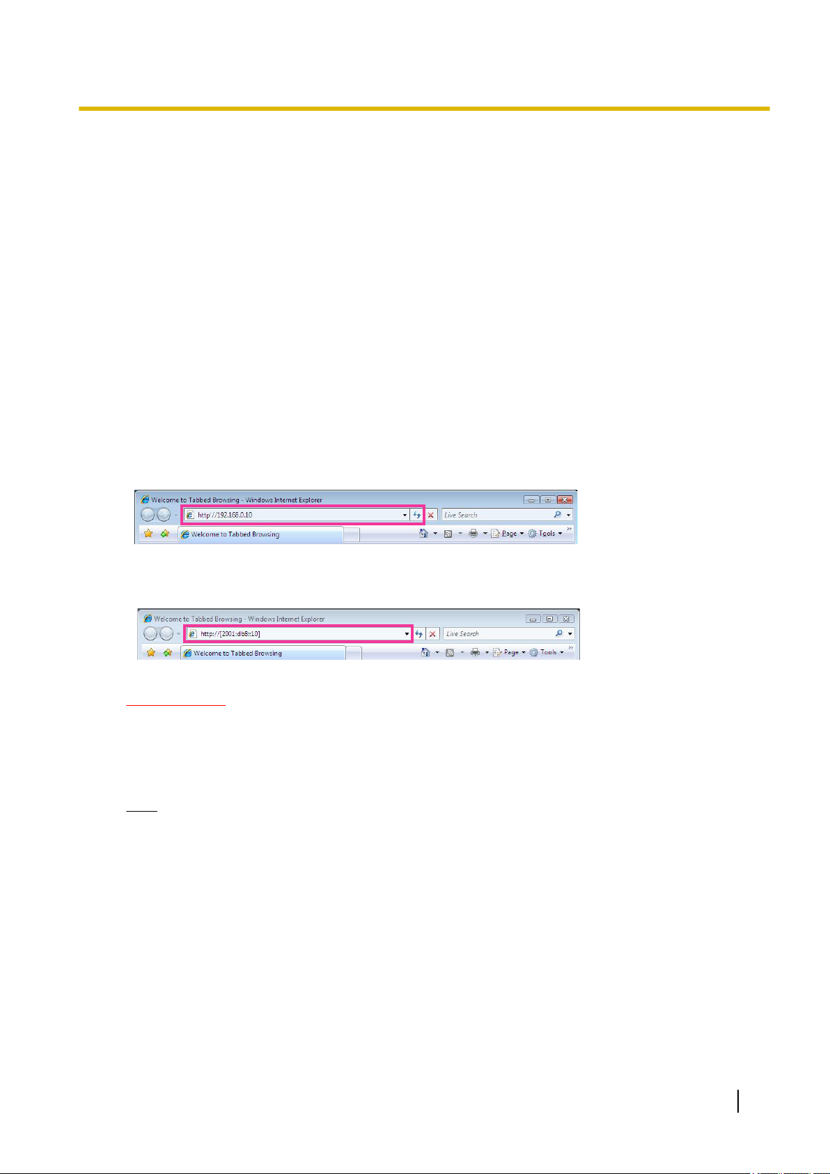
1. Start up the web browser.
2. Enter the IP address designated using the Panasonic “IP Setting Software” in the address box of the
browser.
• Example when entering an IPv4 address: http://URL registered using IPv4 address
http://192.168.0.10/
• Example when entering an IPv6 address: http://[URL registered using IPv6 address]
http://[2001:db8::10]/
<Example of IPv4 access>
1 Operations
<Example of IPv6 access>
IMPORTANT
• When the HTTP port number is changed from “80”, enter “http://IP address of the camera + : (colon)
+ port number” in the address box of the browser. (Example: http://192.168.0.11:8080)
• When the PC is in a local network, configure the proxy server setting of the web browser (under
[Internet Options...] under [Tools] of the menu bar) to bypass the proxy server for the local address.
Note
• Refer to page 163 and page 168 for further information about the case in which “HTTPS” is
selected for “HTTPS” - “Connection” on the [Advanced] tab of the “Network” page (®page 134).
Operating Instructions 9
Page 10
X8570N
S8530N
1 Operations
3. Press the [Enter] key on the keyboard.
→ The “Live” page will be displayed. Refer to page 12 for further information about the “Live” page.
When “On” is selected for “User auth.”, the authentication window will be displayed before displaying live
images for the user name and password entries.
IMPORTANT
• It is recommended to change the password periodically.
• When displaying multiple H.265 (or H.264) images on a PC, images may not be displayed depending
on the performance of the PC.
Note
• The maximum number of concurrent access user is 24including users who is receiving H.265 (or H.
264) images and users who are receiving JPEG images. Depending on the set values for “Bandwidth
control(bit rate)” and “Max bit rate (per client)*”, the maximum concurrent access number may be 24
or less users. When 24 users are concurrently accessing, the access limit message will be displayed
for users who subsequently attempt to access. When “Multicast” is selected for “Transmission type” of
“Stream”, only the first user who accessed to monitor H.265 (or H.264) images will be included in the
maximum number. The second and subsequent users who are monitoring H.265 (or H.264) images
will not be included in the maximum number.
• If you set the “Stream transmission” (®page 80) to “On”, an H.265 (or H.264) image will be displayed
based on the settings of the “Stream encoding format”. If you set the “Stream transmission” (®page
80) to “Off”, a JPEG image will be displayed. A JPEG image can be displayed even if the “Stream
transmission” is set to “On”, but in that case, the transmission interval of the JPEG image will be
restricted.
• The refresh interval may become longer depending on a network environment, PC performance,
photographic subject, access traffic, etc.
<Refresh interval of JPEG images>
When “On” is selected for “Stream transmission”
max. 1 fps (at 3840´2160), max. 2 fps (at 2560´1440), max. 5 fps (at 1280´720, 640´360, 320´180)
max. 5fps
10 Operating Instructions
Page 11

When “Off” is selected for “Stream transmission”
X8570N
S8530N
max. 15fps
max. 30fps
1 Operations
Operating Instructions 11
Page 12

O
A
C
H
M
G
D
E
F
I
J
K
L
N
Q R S T U
V
P
B
1 Operations
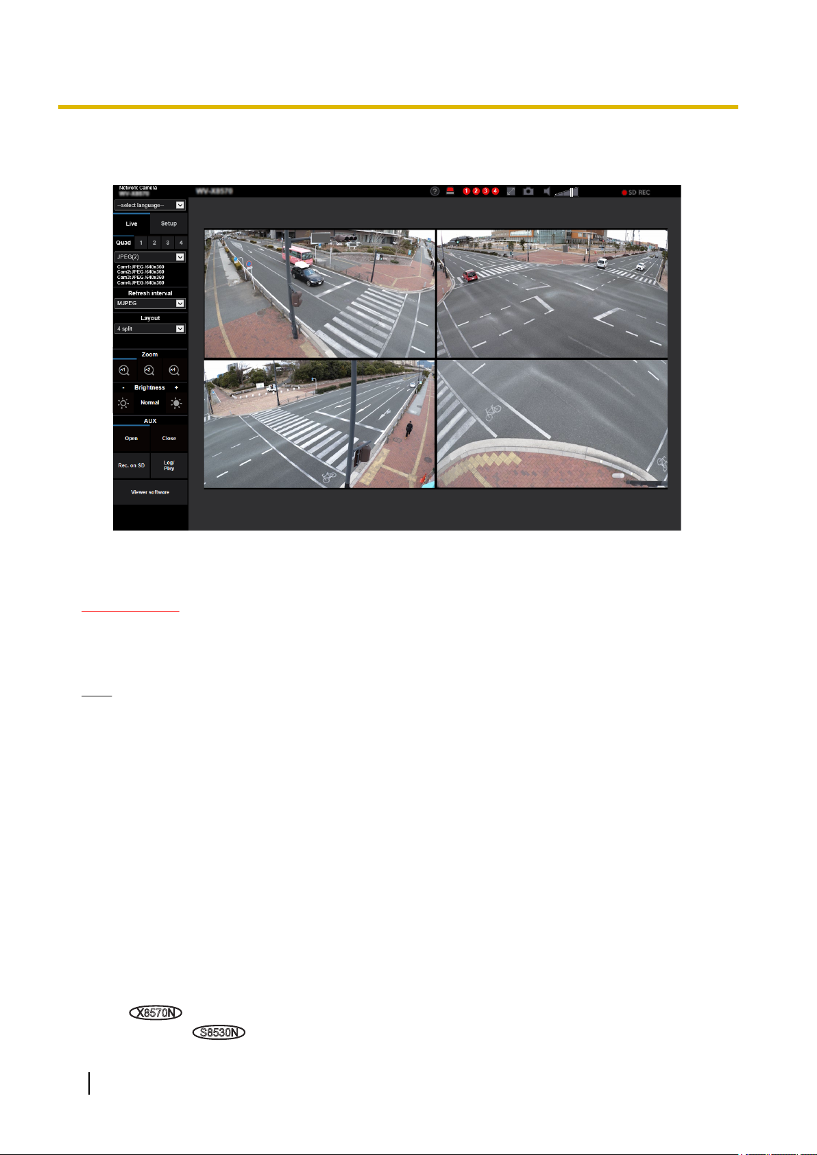
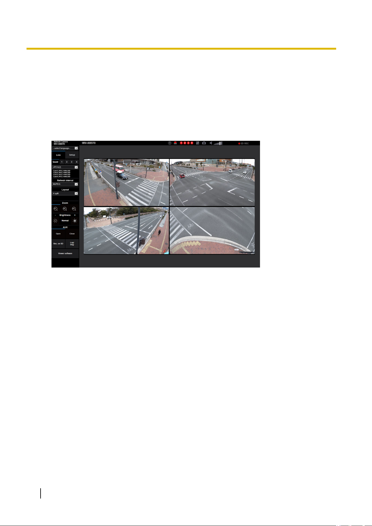
1.1.2 About the “Live” page
Note
• The buttons and setting items displayed on the “Live” page can be changed depending on the user
rights of the accessing user. You can set the user right settings from “User auth.” under “User mng.”.
(®page 126)
[select language] pull-down-menu
The camera’s display language can be selected. The default language can be set in the [Menu language]
in the [Basic] settings. (®page 55)
[Login] button
This button is displayed when “User auth.” is “On” and a person other than the administrator logs in, or
when “User auth.” is “Off” and “Guest User” is set to “Use”. (®page 126)
If login fails, close all the browsers, open the “Live” page and login once again.
[Setup] button
Displays the setup menu.
Select camera to be displayed
Select the camera to be displayed in the main area.
Quad: Displays images of Cam. 1, 2, 3, and 4 in 4-split screen.
1: Displays images from Cam. 1.
2: Displays images from Cam. 2.
3: Displays images from Cam. 3.
12 Operating Instructions
*1
Page 13

1 Operations
4: Displays images from Cam. 4.
[Live view] pull-down menu
You can select and switch to the image to be displayed in the main area from the following:
When “Quad” is selected: Stream(2)/JPEG(2)
When “1”, “2”, “3”, or “4” is selected: Stream(1)/ Stream(2)/ JPEG(1)
The image in the main area is displayed based on the contents set in Stream(1) – (2) (®page 80) or
JPEG(1) – (2) (®page 79).
Also the first stream displayed when you accessed the camera can be set from “Initial display stream” of
the [Image] tab.
Note
• When “1”, “2”, “3”, or “4” is selected and the image capture size is one of “3840´2160”, “2560
´1440”, “1600´1200”, “1920´1080”, “1280´960” or “1280´720”, the image may become smaller
than the actual size depending on the window size of the web browser. When “Quad” is selected,
it may become smaller than the actual size depending on the window size of the web browser.
Stream information display
Displays the setup for stream encoding format, image capture size, bit rate, and frame rate for the live view
of a stream.
Note
• Displays the values set in the stream. The actual bit rate and frame rate vary depending on the
network environment and the used PC.
[Refresh interval] pull-down menu
This pull-down menu will be displayed only when a JPEG image is displayed. Use it to select the display
method of the JPEG image.
• MJPEG: Uses viewer software to display JPEG images successively as MJPEG (Motion JPEG). Not
available if the viewer software is not installed.
• Refresh interval : 1s/Refresh interval : 3s/Refresh interval : 5s/Refresh interval : 10s/Refresh
interval : 30s/Refresh interval : 60s: Refreshes JPEG format (still images) images at the specified
interval.
Note
• Depending on the network environment or the PC used, JPEG format (still images) images may
not be refreshed at the specified interval.
• When “JPEG(2)” is selected for “Quad”, “Refresh interval: 1s” and “Refresh interval: 3s” are not
available.
[Layout] pull-down menu
This pull-down menu will be displayed only when the images are displayed in “Quad”.
Select the layout of the camera images to be displayed in the main are from “4 split”, “360 deg.”, or “270
deg. + right below”.
[Zoom] buttons
Images will be zoomed in on with the electronic zoom by the viewer software “Network Camera View
4S”. When selecting “Quad”, this button will not be displayed.
• [x1] button: The images in the main area will be displayed at x1.
• [x2] button: The images in the main area will be displayed at x2.
• [x4] button: The images in the main area will be displayed at x4.
[Brightness] buttons
The brightness is adjustable from 0 to 255. Click the button to make the image brighter, or click the
button to make the image darker. If you click the [Normal] button, the display will be reset to default.
When selecting “Quad”, this button will not be displayed.
*2
Operating Instructions 13
Page 14

X8570N
X8570N
1 Operations
[AUX] button
These buttons will be displayed only when “Terminal 3” of “Alarm” is set to “AUX output” on the setup menu.
(®page 46)
• [Open] button: The status of the AUX connector will be open.
• [Close] button: The status of the AUX connector will be closed.
Note
[Rec. on SD] button
The [Rec. on SD] button will be displayed only when “Manual” is selected for “Save trigger” on the [SD
memory card] tab. (®page 66)
Click this button to manually record images on the SD memory card. Refer to page 24 for descriptions
of how to manually record images on the SD memory card.
[Log] button
When the [Log] button is clicked, the log list will be displayed and images saved on the SD memory card
can be played.
Refer to page 28 for further information about the log list and for how to play images on the SD memory
card.
[Viewer Software] button
Starts installation of the viewer software for display. This button will not be available if the viewer software
is already installed on the PC, or if the “Automatic installation” of the [Viewer software
(nwcv4Ssetup.exe)] in the [Basic] tab is set to “Off”. (®Page 59)
Camera title
The camera title entered for “Camera title” on the [Basic] tab will be displayed. (®page 56)
Support button
When this button is clicked, the support site below will be displayed in a newly opened window. This website
contains technical information, FAQ, and other information.
https://security.panasonic.com/support/
Alarm occurrence indication button
This button will blink at an alarm occurrence, and the camera of alarm occurrence (one of (1) to (4) buttons)
will light. When this button is clicked, all the alarm output terminal will be reset
will disappear. (®page 26)
• The names of “AUX”, “Open” and “Close” can be changed. (®page 112)
*2
*2
and this button
Note
• Since the blinking of the alarm occurrence indication button is not coupled to recording images to
the SD memory card, forwarding E-mails, or other operations, check the settings of each operation
separately.
Full screen button
Images will be displayed on a full screen. If the full screen button is clicked once when the image displayed
in the main area is smaller than the main area, the image is displayed corresponding to its image capture
size. If the full screen button is clicked once when images are displayed corresponding to their image
capture sizes, images are displayed in full screen. To return to the “Live” page when displaying an image
in full screen, press the [Esc] key. When selecting “Quad”, this button will not be displayed.
Snap shot button
Click this button to take a picture (a still picture). The picture will be displayed on a newly opened window.
When right-clicking on the displayed image, the pop-up menu will be displayed. It is possible to save the
image on the PC by selecting “Save” from the displayed pop-up menu.
When “Print” is selected, printer output is enabled. When selecting “Quad”, this button will not be displayed.
Note
• The pop-up menu [Save] and [Print] will not be displayed if the viewer software is not installed.
• The following settings may be required.
14 Operating Instructions
Page 15

X8570N
1 Operations
Open Internet Explorer, click [Tools] ® [Internet Options] ® [Security] ® [Trusted Sites] ®
[Sites]. Register the camera address on [Website] of the displayed trusted windows. After
registration, close the web browser, and then access the camera again.
• When it takes longer than the specified period to obtain the snap shot picture due to the network
environment, the snap shot picture may not be displayed.
• If the image capture size specified for JPEG cannot be obtained, JPEG images are displayed with
the image capture size that could be obtained.
Therefore, when JPEG images obtained with snap shot are displayed on a PC, the displayed image
size may differ from the captured sized.
Mic input button
Turns on/off the audio reception (hear audio from the camera on a PC). This button will be displayed only
when “Mic input” is selected for “Audio transmission mode” in the setup menu. (®page 106)
When the audio reception is turned off, the button will turn into the
button and audio from the camera
will not be heard.
Audio volume can be adjusted (Low/ Middle/ High) by moving the volume cursor .
Note
• When “Adjust Mic input” is set to “Audio volume control mode” in the setup menu, the volume cursor
is not displayed when using “Audio recording”.
• When the camera is restarted, the adjusted volume level (for the reception) will return to the level
that had been set on the [Audio] tab on the setup menu. (®page 106)
• Actual volume level will change in three steps even though the volume cursor can be adjusted
minutely.
• If multiple camera browsers are open at the same time on the same computer, audio cannot be
heard from the camera browsers that were opened later. Please only access 1 camera at a time.
SD recording status indicator
The status of the SD recording can be checked with this indicator.
When the SD recording starts, the SD recording status indicator will light red. It will go off when the SD
recording stops.
This indicator will be displayed when “Manual” or “Schedule” is selected for “Save trigger” on the setup
menu. (®page 62)
Main area
Images from the camera will be displayed in this area.
The current time and date will be displayed according to the settings configured for “Time display format”
and “Date/time display format”. (®page 55)
In addition, when being adjusted, the status of brightness (®Page 58) will be displayed as well as the
characters configured for “Camera title on screen” (®Page 57).
A zoom operation can be performed using the mouse wheel. (except “Quad”)
When clicking a desired point while displaying live images at x2 or x4 in the main area, the camera will
move to locate the clicked point at the center of the main area.
Note
• When the camera is operated by a user with a low access level, images displayed on the screen
may be changed temporarily. This does not affect operation of the camera.
• Depending on the PC in use, screen tearing* may occur when the shooting scene drastically
changes due to the GDI restrictions of the OS.
*A phenomenon in which portions of the screen are displayed out of alignment.
*1
Only operable by users whose access level is “1. Administrator”.
*2
Only operable by users whose access level is “1. Administrator” or “2. Camera control” when “On” is selected for “User
auth.” (®page 126)
Operating Instructions 15
Page 16

1 Operations
1.2 Monitor images on a mobile terminal or tablet device
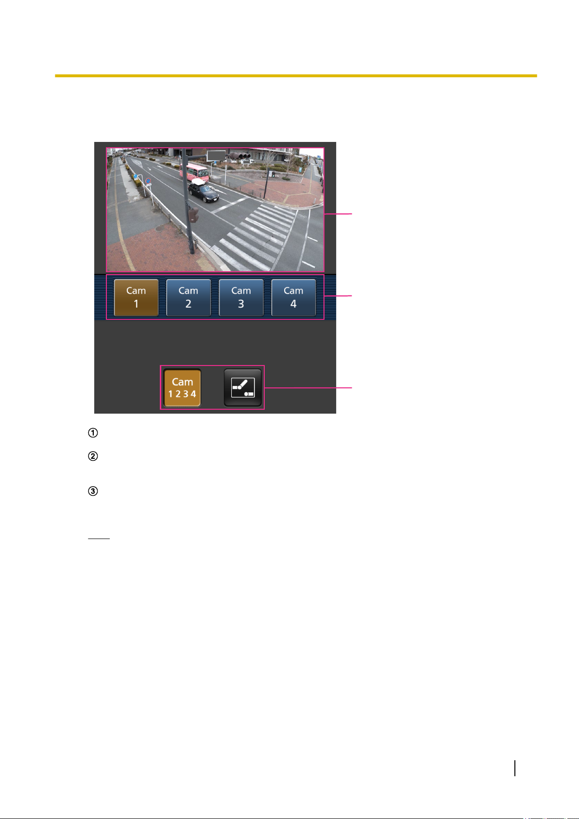
1.2.1 Monitor images on a mobile terminal (including smartphones)
It is possible to connect to the camera using a mobile terminal via the Internet and monitor images (MJPEG
or JPEG) from the camera on the screen of the mobile terminal. It is also possible to refresh images to display
the latest image.
The compatible mobile terminals are shown as follows. (As of March, 2018)
– iPad, iPhone (iOS 4.2.1 or later)
– Android™ mobile terminals
When an Android terminal is used, an MJPEG format image is displayed by the Firefox® browser, and a JPEG
format image is displayed by the standard browser.
For further information about compatible devices, refer to our website.
(https://security.panasonic.com/support/info/ <Control No.: C0108>)
IMPORTANT
• When the authentication window is displayed, enter the user name and password.
To enhance the security, it is recommended to change the password periodically. (®page 126)
Note
• It is necessary to configure the network settings of the mobile terminal in advance to connect to the
Internet and monitor images from the camera. (®page 134)
16 Operating Instructions
Page 17
C
B
A
1 Operations
1. Access to “http://IP address/cam”
*1
or “http://Host name registered in the DDNS server/cam”*2 using a
mobile terminal.
→ Images from the camera will be displayed.
Live images area
Displays images from the camera.
Operation buttons area
When functions are selected in the function selection area C, buttons to operate those functions are
displayed.
Function selection area
When functions that can be operated are selected, operation buttons are displayed in the operation
buttons area B.
Note
• The operations button displayed on the mobile terminal screen may not be available depending on
the user rights and access level of the accessing user. To display the operations button, it is
necessary to set the user rights and access level (“User auth.” in “User mng.”). (®page 126)
Operating Instructions 17
Page 18
A B
X8570N
1 Operations
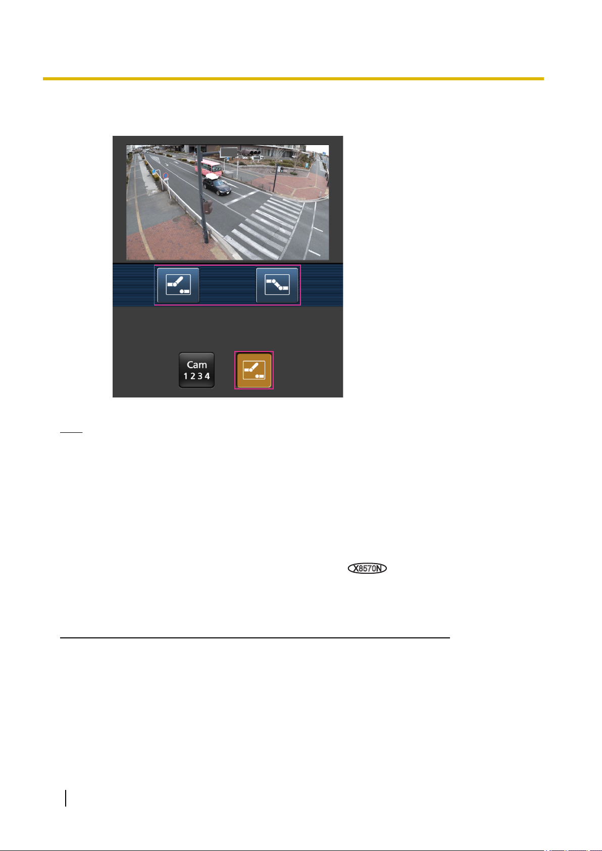
2. Click the button of the function that you want to operate.
Switch camera
AUX control
Each function is explained below.
Switch camera
Press this button to display the buttons used to select the camera on the screen.
The camera to be displayed can be switched by selecting one of the displayed buttons.
18 Operating Instructions
Page 19
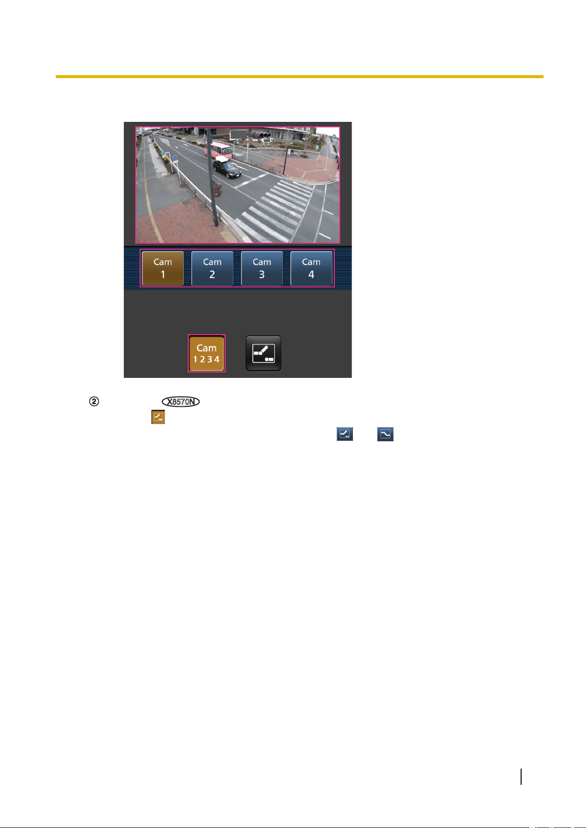
The images from Cam. 1, 2, 3, or 4 are displayed in 640x360 or JPEG of VGA.
X8570N
1 Operations
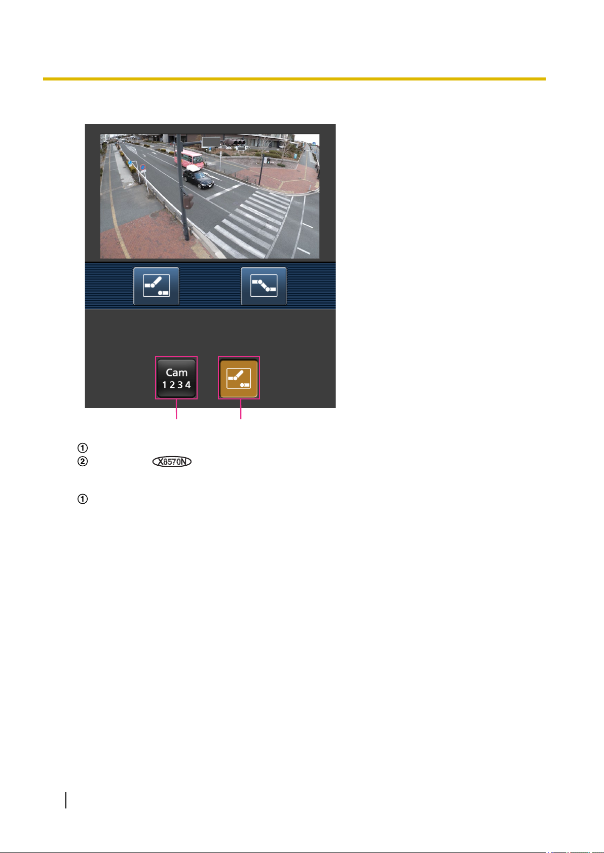
AUX control
Press the button to display the buttons used to operate the AUX output on the screen.
The AUX output terminals can be controlled with the and buttons.
Operating Instructions 19
Page 20
X8570N
1 Operations
This function is only displayed when [Terminal 3] is set to [AUX output] on the settings menu.
(®page 46)
Note
• When the HTTP port number is changed from “80”, enter “http://IP address: (colon) + port number/
cam”*1 in the address box of the browser. When using the DDNS function, access to “http://Host name
registered in the DDNS server: (colon) + port number/cam”*2.
• When “HTTPS” is selected for “HTTPS” - “Connection” on the [Advanced] tab of the “Network” page,
enter as follows.
“https://IP address: (colon) + port number/cam” or “https://Host name registered in the DDNS server:
(colon) + port number/cam”
• When the authentication window is displayed, enter the user name of an administrator or user and
password. Depending on the mobile terminal in use, password entry may be required each time the
screen is switched.
• It is impossible to receive audio using a mobile terminal.
• Depending on the mobile terminal in use, larger size images may not be displayed. In this case,
selecting a setting close to the lowest quality setting for “Image quality setting” of “JPEG” (®page
78) may sometimes solve this problem.
• Depending on the mobile terminal in use or its contract plan, it may be impossible to access.
*1
IP address is the global WAN IP address of the router that can be accessed via the Internet. However, when accessing the same
LAN as the camera with a wireless compatible mobile terminal, the IP address is the local IP address.
*2
Only when accessing the camera via the Internet.
1.2.2 Monitor images on a tablet device
It is possible to connect to the camera using a tablet device via the Internet and monitor images (MJPEG or
JPEG) from the camera on the screen of the tablet device. It is also possible to refresh images to display the
latest image.
20 Operating Instructions
Page 21
C D
G
H
I
J
K
F
Setup menu
E
A
B
1 Operations
The compatible mobile terminals are shown as follows. (As of March, 2018)
– iPad, iPhone (iOS 4.2.1 or later)
– Android™ mobile terminals
When an Android terminal is used, an MJPEG format image is displayed by the Firefox® browser, and a JPEG
format image is displayed by the standard browser.
For further information about compatible devices, refer to our website
(https://security.panasonic.com/support/info/ <Control No.: C0108>).
IMPORTANT
• When the authentication window is displayed, enter the user name and password.
To enhance the security, it is recommended to change the password periodically. (®page 126)
Note
• It is necessary to configure the network settings of the tablet device in advance to connect to the Internet
and monitor images from the camera. (®page 134)
• Depending on the device model, the same screen as the PC may be displayed. In that case, access
to “http://IP address/live/tab.html” or “http://Host name registered in the DDNS server/live/tab.html”.
• A mobile terminal can be connected. However, it is recommended to use a tablet device since the
screen is optimized for the tablet devices.
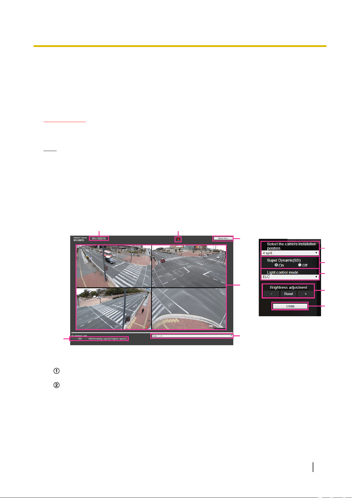
1. Access to “http://IP address/” or “http://Host name registered in the DDNS server/” using a tablet device.
→ Images from the camera will be displayed.
[Setup menu] button
*1
Displays the setup menu.
Display camera switching pull-down menu
Selects the camera image to be displayed in the display area E.
Cam. 1-4: Displays camera images of Cam. 1, 2, 3, and 4 simultaneously. The display is subject to the
settings of “G Layout setup pull-down menu”.
Cam. 1: Displays live images from Cam. 1 on a 1-split screen.
Cam. 2: Displays live images from Cam. 2 on a 1-split screen.
Cam. 3: Displays live images from Cam. 3 on a 1-split screen.
Cam. 4: Displays live images from Cam. 4 on a 1-split screen.
Default: Cam. 1-4
Operating Instructions 21
Page 22

1 Operations
Camera title
The camera title entered for “Camera title” on the [Basic] tab will be displayed. (®page 56)
Alarm occurrence indication button
*2
When an alarm occurs, the display flashes. When this button is clicked, the output terminal will be reset
and this button will disappear. (®page 26)
Note
• Since the blinking of the alarm occurrence indication button is not coupled to recording images
to the SD memory card, forwarding E-mails, or other operations, check the settings of each
operation separately.
Main area
The live images from the camera will be displayed in this area.
Remaining capacity
Displays the remaining capacity and total capacity of the SD memory card.
Layout setup pull-down menu
Select the layout of the camera images to be displayed in the area E from “4 split”, “360 deg.”, or “270
deg. + right below”. The layout setting pull-down menu is displayed when “Cam. 1-4” is selected in the
display camera switching pull-down menu.
360 deg.: Displays the images of Cam. 1, 2, 3, and 4 in “360 deg.”. Select when installing the camera
4 horizontally in order to shoot the surroundings widely. When it is selected, the setting of
“Upside-down” of the camera 4 will be changed to “Off”.
270 deg. + right below: Displays the images of Cam. 1, 2, 3, and 4 in “270 deg. + right below”. Select
when installing the camera 4 facing downward in order to shoot the surrounding and right below. When
it is selected, the setting of “Upside-down” of the camera 4 will be changed to “On”.
4 split: Displays the images of Cam. 1, 2, 3, and 4 in the 4 Screens. The “Upside-down” setting of
Cam. 4 is maintained.
Default: 360 deg.
Super Dynamic setting
Select “On” or “Off” to determine whether or not to activate the super dynamic function. Refer to the
description “Super Dynamic function” (®page 89) about the super dynamic function.
On: The super dynamic function will work.
Off: The super dynamic function will not work.
Default: On
Note
• When the following are observed depending on the light condition, select “Off” for “Super
Dynamic(SD)”.
– When flickering appears or the color changes on the screen
– When noise appears in the brighter area on the screen
[Light control mode] pull-down menu
Select the light control mode from the following.
Indoor scene (50 Hz)/Indoor scene (60 Hz): The shutter speed will automatically be adjusted to
prevent flicker caused by fluorescent light. Select 50 Hz or 60 Hz corresponding to the location where
the camera is in use.
ELC: Uses shutter speed adjustment to control light.
Default: ELC
[Brightness adjustment] button
Adjust the brightness. The [Brightness adjustment] button is not displayed when Cam. 1-4 is selected
with the display camera switching pull-down menu.
Click the [+] button to make the image brighter.
Click the [-] button to make the image darker.
Click the [Reset] button to reset to the default brightness setting.
[Close] button
Close the setup menu.
22 Operating Instructions
Page 23

X8570N
1 Operations
Note
• When the HTTP port number is changed from “80”, enter “http://IP address: (colon) + port number”
the address box of the browser. When using the DDNS function, access to “http://Host name registered
in the DDNS server: (colon) + port number”*3.
• When “HTTPS” is selected for “HTTPS” - “Connection” on the [Advanced] tab of the “Network” page,
enter as follows.
“https://IP address: (colon) + port number” or “https://Host name registered in the DDNS server: (colon)
+ port number”
• When the authentication window is displayed, enter the user name of an administrator or user and
password. Depending on the mobile terminal in use, password entry may be required each time the
screen is switched.
• It is impossible to receive audio using a tablet device.
• Depending on the tablet device in use, larger size images may not be displayed. In this case, selecting
a setting close to the lowest quality setting for “Image quality setting” of “JPEG” (®page 78) may
sometimes solve this problem.
• Depending on the tablet device in use or its contract plan, it may be impossible to access.
*1
Only operable by users whose access level is “1. Administrator”.
*2
Only operable by users whose access level is “1. Administrator” or “2. Camera control” when “On” is selected for “User
auth.” (®page 127)
*3
Only when accessing the camera via the Internet.
*1
in
Operating Instructions 23
Page 24
1 Operations
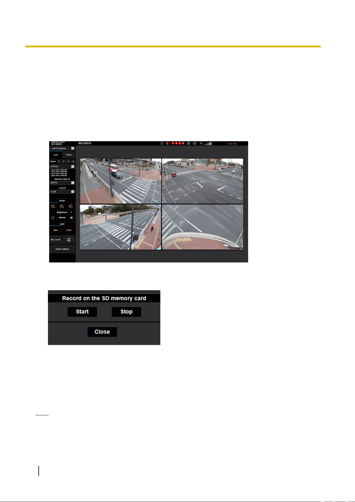
1.3 Record images on the SD memory card manually
Images displayed on the “Live” page can be recorded on the SD memory card manually. This button is operable
only when “Manual” is selected for “Save trigger” on the [SD memory card] tab on the “Basic” page of the setup
menu. (®page 66)
It is possible to select the stream to record from “Stream(1) Cam. 1” to “Stream(1) Cam. 4” or “Stream(2)
Cam. 1” to “Stream(2) Cam. 4” on “Recording format” of the setup menu (®page 65). When “Manual” is
selected, Cam. 1, 2, 3, and 4 are simultaneously recorded.
Images recorded on the SD memory card can be copied onto the PC. (®page 75)
1. Display the “Live” page. (®page 9)
2. Click the [Rec. on SD] button.
→ The SD recording window will open.
3. Click the [Start] button to start recording images on the SD memory card. The SD recording status indicator
will light red (®page 12) while images are being recorded on the SD memory card.
The image saving interval can be configured on the [SD memory card] tab of the “Basic” page.
(®page 62)
4. Click the [Stop] button to stop saving images on the SD memory card.
® The SD recording status indicator will turn off.
5. Click the [Close] button to close the window.
Note
• Image data saved on Drive B can be obtained by executing “Access img.” on the [SD memory card]
tab and logging in from the user authentication window (®page 75).
The destination to save image data is a fixed directory on Drive B (®page 211).
24 Operating Instructions
Page 25

1 Operations
• When the [Start] button is clicked immediately after the [Stop] button is clicked, saving of images may
not start. In this case, click the [Start] button again.
Operating Instructions 25
Page 26

X8570N
X8570N
1 Operations
1.4 Action at an alarm occurrence
The alarm action (camera action at an alarm occurrence) will be performed when the following alarms occur.
1.4.1 Alarm type
• Terminal alarm: When connecting an alarm device such as a sensor to the alarm input terminal of the
camera, the alarm action will be performed when the connected alarm device is activated.
• VMD alarm: When motion is detected in the set VMD area, the alarm action will be performed.
*VMD stands for “Video Motion Detection”.
• Command alarm: When a Panasonic alarm protocol is received from the connected device via a network,
the alarm action will be performed.
1.4.2 Action at an alarm occurrence
Display the alarm occurrence indication button on the “Live” page
The alarm occurrence indication button will be displayed on the “Live” page at an alarm occurrence.
(®page 12)
IMPORTANT
• When “Polling(30s)” is selected for “Status update mode” (®page 55), the Alarm occurrence
indication button will be refreshed in 30-second intervals. For this reason, it may take a maximum of
30 seconds until the alarm occurrence indication button is displayed on the “Live” page at an alarm
occurrence.
Notify of alarm occurrences to the device connected to the output terminal
It is possible to output signals from the output terminal of the camera and sound the buzzer when an alarm
occurs. The settings for the alarm output can be configured in the [Alarm] tab of the “Alarm” page.
(®page 110)
Save images on the SD memory card
When an alarm occurs, images (H.265/H.264) will be saved on the SD memory card. The settings to save
images on the SD memory card can be configured on the [SD memory card] tab (®page 62) of the “Basic”
page and the [Alarm] tab of the “Alarm” page. (®page 113)
Notify of alarm occurrences by E-mail
Alarm E-mail (alarm occurrence notification) can be sent at an alarm occurrence to the E-mail addresses
registered in advance. Up to 4 addresses can be registered as recipients of the alarm E-mail. An alarm image
(still picture) can be sent with the alarm E-mail as an attached file. The settings for alarm E-mail can be
configured in the “Alarm E-mail notification” section on the [Alarm] tab of the “Alarm” page (®page 113) and
the [Advanced] tab of the “Network” page (®page 139).
26 Operating Instructions
Page 27

1 Operations
Notify of alarm occurrences to the designated addresses (Panasonic alarm
protocol notification)
This function is available only when a Panasonic device, such as the network disk recorder, is connected to
the system. When “On” is selected for “Panasonic alarm protocol”, the connected Panasonic device will be
notified that the camera is in the alarm state. The settings for Panasonic alarm protocol can be configured in
the “Panasonic alarm protocol notification” section of the [Notification] tab of the “Alarm” page. (®page 122)
Notify of alarm occurrences to the designated HTTP server (HTTP alarm
notification)
Alarm occurrence notifications can be sent at an alarm occurrence to the HTTP servers registered in advance.
Up to 5 HTTP servers can be registered as recipients of alarm notifications. The URL sent to HTTP servers
with alarm notifications can be specified. The settings for HTTP alarm notification can be configured on the
[Notification] tab of the “Alarm” page. (®page 124)
Operating Instructions 27
Page 28
1 Operations
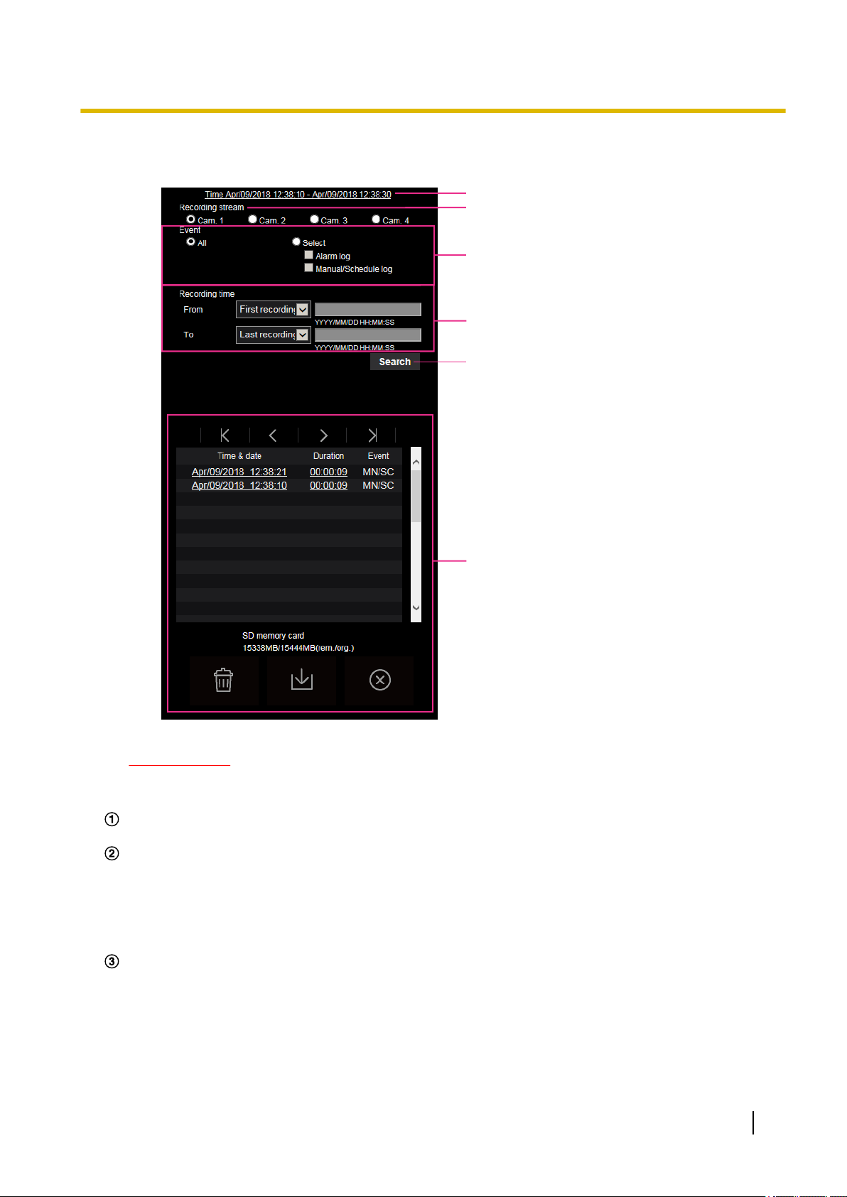
1.5 Display the log list
The history of various logs will be displayed in list form.
• Alarm log: Logs of the alarm occurrences such as time and date of the alarm occurrences, the image
recording period and the alarm type will be displayed.
• Manual/Schedule log: Logs filed when images have been recorded manually or during the period of the
schedule, and the image recording period will be displayed.
1. Display the “Live” page.
28 Operating Instructions
Page 29
2. Click the [Log] button.
A
B
C
D
E
F
→ The log list will be displayed in a newly opened window (log list window).
1 Operations
IMPORTANT
• Only a single user can operate the log list window. Other users cannot access the log list window.
Time
Displays the time period of the data recorded on the SD memory card.
Recording stream
Select the recording stream that you want to display logs for.
• Cam. 1: The logs recorded by “Recording stream” of Cam. 1 will be displayed.
• Cam. 2: The logs recorded by “Recording stream” of Cam. 2 will be displayed.
• Cam. 3: The logs recorded by “Recording stream” of Cam. 3 will be displayed.
• Cam. 4: The logs recorded by “Recording stream” of Cam. 4 will be displayed.
Event
Select a log type to display on the log list.
• All: All logs will be displayed.
• Select: Only the logs of the selected log type will be displayed.
– Alarm log: The log when an alarm is detected will be displayed.
– Manual/Schedule log: Manual and Schedule logs will be displayed.
• Default: All
Operating Instructions 29
Page 30

X8570N
X8570N
X8570N
1 Operations
Recording time
Configure the time period of logs displayed on the log list.
• From: Configure the starting period of logs displayed on the log list.
• To: Configure the ending period of logs displayed on the log list when “First recording” or “Date/time”
[Search] button
Searches for logs according to the conditions specified in “Event” and “Recording time”.
The search result will be displayed on the log list.
Log list
Displays the log search results.
You can play back recorded data by clicking on the time or duration of the recorded data displayed under
[Time & date] and [Duration].
– First recording: Displays from the first log recorded on the SD memory card.
– Today: Displays the logs recorded today.
– Yesterday: Displays the logs recorded from yesterday to the present day.
– Last 7 days: Displays the logs recorded from 6 days ago to the present day.
– Last 30 days: Displays the logs recorded from 29 days ago to the present day.
– Date/time: Displays the logs recorded from the entered date and time on “Date/time” box.
is selected for “From”.
– Last recording: Displays until the last log recorded on the SD memory card.
– Date/time: Displays the logs recorded until the entered date and time on “Date/time” box.
•
(Top) button: Click this button to display the log listed at the top.
• (Prev. page) button: Click this button to display the previous page of the log list.
• (Next page) button: Click this button to display the next page of the log list.
•
(Last) button: Click this button to display the log listed at the bottom.
• [Time & date]: Time and date when each log has been recorded will be displayed.
Note
• When “Off” is selected for “Time display format”, the alarm occurrence times are displayed in
24 hour time format.
• The recording timing of logs is as follows.
– Alarm log: Alarm occurrence time and date will be filed as a log.
– Manual/Schedule log: Time and date when recording of images onto the SD memory card
started manually or during the period of the schedule will be filed as a log. In sequential
recording, the logs will be filed every hour from the time when recording is started. The
timing of log recording may differ among Camera 1 to 4.
• [Duration]: Displays the period of time that the data has been recorded on the SD memory card.
Note
• The difference between the recording end time and recording start time of the image is
calculated by rounding off to the nearest tenth of a second.
• [Event]: The event type will be displayed.
– MN/SC: Log by “Manual/Schedule”
– TRM1
– TRM2
– TRM3
: Alarm by alarm input to Terminal 1
: Alarm by alarm input to Terminal 2
: Alarm by alarm input to Terminal 3
– VMD: Alarm by VMD alarm
– COM: Alarm by command alarm
30 Operating Instructions
Page 31

1 Operations
• [SD memory card]: Available capacity and the original capacity of the SD memory card will be
displayed.
•
(Delete) button: Deletes log lists from all pages. When logs are searched for, only the searched
logs are deleted. Images associated with deleted logs will also be deleted.
IMPORTANT
• If there are many recorded data files on the SD memory card, it may take time to delete all of
them. (For example, when the total size is 1 GB, it may take about 1 hour to delete the files.)
In this case, format the SD memory card. However, please note that formatting will delete all
of the files on the SD memory card.
• In the process of the deletion, “Alarm” and “Manual/Schedule” cannot be operated.
• Do not turn off the power of the camera until the deletion is complete. When the power of the
camera is turned off in the process of the deletion, some images may remain on the SD memory
card. In this case, click the button on the same log list window used to delete the logs.
•
(Download) button: Click this button to download all logs of the selected log list onto the PC.
Note
• The following settings may be required.
Open Internet Explorer, click [Tools] ® [Internet Options] ® [Security] ® [Trusted Sites] ®
[Sites]. Register the camera address on [Website] of the displayed trusted windows.
After registration, close the web browser, and then access the camera again.
• Up to 50,000 logs per camera can be downloaded to the SD memory card. When more than
50,000 logs are filed, the older logs will be overwritten by the newer logs. In this case, the oldest
log is the first to be overwritten.
If there are many logs, it may take time to download the logs.
•
(Close) button: Click this button to close the log list window.
Operating Instructions 31
Page 32

1 Operations
1.6 Playback of images on the SD memory card
When clicking a time and date listed on the log list window, the “Live” page will turn to the “Playback” page.
When images associated with the clicked time and date are on the SD memory card, the first image of them
will be displayed.
IMPORTANT
• Refresh interval of images may become slow during playback or download.
• When many images are saved on the SD memory card, it may take time to display images on the
“Playback” page.
• When the aspect ratio is “4:3”, images will be displayed in VGA size on the “Playback” page regardless
of the image capture size of the images saved on the SD memory card. When the aspect ratio is
“16:9”, images will be displayed in “640x360” on the “Playback” page regardless of the image capture
size of the images saved on the SD memory card. Therefore, images may look coarse on the
“Playback” page.
• The playback refresh interval may become slower when recording data to the SD memory card.
Note
• The streams of Cam. 1, 2, 3, and 4 cannot be played back simultaneously. The playback can be
performed by single camera.
32 Operating Instructions
Page 33

A
X8570N
1 Operations
1.6.1 Playback “Stream(1)”/“Stream(2)” images saved to the SD memory card
IMPORTANT
• Depending on the network environment, download of video data may fail. If downloading failed while
playing images, you may be able to download images after stopping the currently played images and
starting the download again.
• Depending on the network environment and status of the camera, you may not be able to operate each
operation on this screen consecutively.
Slider bar
By operating the slider bar, you can select where to start playing images from. The slider bar can only be
used before playing images, or when playing is paused or stopped.
(PAUSE) button
Playback will be paused when this button is clicked during playback.
(PLAY) button
When this button is clicked, recorded data will be played.
Note
• If audio is recorded, it can be played back, but the image and audio will not be synchronized. Therefore,
images and audio may not always match. When data is being recorded to the SD memory card, audio
may sound as if it is cutting out and the audio quality may be reduced.
• When recorded audio is played back, the refresh interval of live images and playback may become
slow.
Operating Instructions 33
Page 34

X8570N
X8570N
X8570N
X8570N
1 Operations
• Recorded audio is not played back when “Off” is selected for “Audio transmission mode” on the
[Audio] tab of the “Image/Audio” page.
(FF) button
Each time this button is clicked, the playback speed will change. When the button is clicked during fast
playback, playback speed will return to the normal playback speed.
Note
• The maximum speed of the fast playback varies depending on the setting of “Bit rate” - “Stream
recording” of the SD memory card.
• Recorded audio will not be played back during fast playback.
(5s backward) button
Each time this button is clicked, the recorded data goes back by 5 seconds and starts playing.
(5s forward) button
Each time this button is clicked, the recorded data goes forward by 5 seconds and starts playing.
(STOP) button
Playback will stop and the “Playback” window will turn to the “Live” page.
[Time & date]
Time and date when each log has been recorded will be displayed.
[Duration]
Displays the period of time that the data has been recorded on the SD memory card.
[Event]
The event type will be displayed.
• MN/SC: Log by “Manual/Schedule”
• TRM1
• TRM2
• TRM3
: Alarm by alarm input to Terminal 1
: Alarm by alarm input to Terminal 2
: Alarm by alarm input to Terminal 3
• VMD: Alarm by VMD alarm
• COM: Alarm by command alarm
(Start) button
The selected image will be downloaded onto the PC.
Before downloading images, designate the destination directory in advance. (®page 76)
The message window will be displayed to ask if it is OK to start download when the
the [OK] button.
button is clicked. Click
Note
• The image playing screen cannot be operated while downloading. Perform operations after the
downloading is completed.
• When the [Cancel] button is clicked in the process of the download, the download will be canceled. In
this case, video data already downloaded before clicking the [Cancel] button will be saved on the PC.
• Video data are saved in the files of approx. 20 MB. When the file size of video data is more than 20
MB, two or more files will be downloaded.
34 Operating Instructions
Page 35

1 Operations
• It is possible to play back H.264 video data saved on the PC using such applications as Windows
Media® Player. However, we are not liable for performance relating to these applications.
• Depending on the status of the SD memory card or Windows Media Player, H.264 video data cannot
be played back.
• For information on playing back H.265 video data, refer to the following Panasonic website below.
https://security.panasonic.com/support/info/ <Control No.: C0303>
Operating Instructions 35
Page 36

2 Settings
2 Settings
2.1 About the network security
2.1.1 Equipped security functions
The following security functions are featured in this camera.
Access restrictions by the host authentication and the user authentication
It is possible to restrict users from accessing the camera by setting the host authentication and/or the user
authentication to “On”. (®page 126, page 129)
Access restrictions by changing the HTTP port
It is possible to prevent illegal access such as port scanning, etc. by changing the HTTP port number.
(®page 136)
Access encryption by the HTTPS function
It is possible to enhance the network security by encrypting the access to cameras using the HTTPS
function. (®page 152)
IMPORTANT
• Design and enhance security countermeasures to prevent leakage of information such as image data,
authentication information (user name and password), alarm E-mail information, DDNS server
information, etc. Perform the countermeasure such as access restriction (using the user authentication)
or access encryption (using the HTTPS function).
• After the camera is accessed by the administrator, make sure to close the browser for added security.
• Change the administrator password periodically for added security.
Note
• When user authentication (authentication error) has failed to pass 8 times within 30 seconds using the
same IP address (PC), access to the camera will be denied for a while.
36 Operating Instructions
Page 37

2.2 Display the setup menu from a PC
The settings of the camera can be configured on the setup menu.
IMPORTANT
• The setup menu is only operable by users whose access level is “1. Administrator”. Refer to
page 126 for how to configure the access level.
2.2.1 How to display the setup menu
1. Display the “Live” page. (®page 9)
2. Click the [Setup] button on the “Live” page.
→ The setup menu will be displayed. Refer to page 39 for further information about this menu.
2 Settings
Operating Instructions 37
Page 38

A B
A
A-1
B
B-1
2 Settings
2.2.2 How to operate the setup menu
Menu buttons
Setup page
1. Click the desired button in the frame on the left of the window to display the respective setup menu.
When there are tabs at the top of the “Setup” page displayed in the frame on the right of the window, click
the desired tab to display and configure the setting items relating to the name of the tab.
2. Complete each setting item displayed in the frame on the right of the window.
3. After completing each setting item, click the [Set] button to apply them.
IMPORTANT
• When there are two or more [Set], [Register], and [Execute] buttons on the page, click the respective
button to the edited setting item.
<Example>
When completing the setting items in field A, click the [Set] button (B) below field (A).
The edited settings in field A will not be applied unless the [Set] button (B) below field (A) is clicked.
In the same manner as above, click the [Set] button (D) below field C when completing the setting
items in field C.
38 Operating Instructions
Page 39

2.2.3 About the setup menu window
A
B
C
D
E
F
G
H
I
J
K
L
M
X8570N
S8530N
X8570N
S8530N
X8570N
S8530N
2 Settings
[Setup] button
Display the “Setup” page.
[Live] button
Display the “Live” page.
[Easy Setup] button
Displays the “Easy Setup” page. The “Easy Setup” page is used to set up Easy installation, the connectivity
to the Internet, as well as event actions such as alarm settings and camera action on alarm.
(®page 41)
[Basic] button
Displays the “Basic” page. The basic settings such as time and date and camera title, and the settings
relating to the SD memory card can be configured on the “Basic” page. (®page 55)
[Image/Audio] button
Displays the “Image/Audio” page
[Image] button
, “Image” page
. The settings relating to the camera
such as image quality, image capture size, etc. of JPEG, H.265, and H.264 can be configured on the
“Image/Audio” page
or “Image” page
. (®page 77)
[Alarm] button
Displays the “Alarm” page. The settings relating to alarm occurrences such as settings for the alarm action
at an alarm occurrence, the alarm occurrence notification, and the VMD area settings can be configured
on the “Alarm” page. (®page 108)
[User mng.] button
Displays the “User mng.” page. The settings relating to the authentication such as users and PCs
restrictions for accessing the camera can be configured on the “User mng.” page. (®page 126)
[Network] button
Displays the “Network” page. The network settings and the settings relating to DDNS (Dynamic DNS),
SNMP (Simple Network Management Protocol), the NTP server, and QoS can be configured on the
“Network” page. (®page 134)
Operating Instructions 39
Page 40

2 Settings
[Schedule] button
Displays the “Schedule” page. On the “Schedule” page, it is possible to designate time zones to allow to
activate the VMD detection function. (®page 175)
[Maintenance] button
Displays the “Maintenance” page. System log check, firmware upgrade, status check and initialization of
the setup menu can be carried out on the “Maintenance” page. (®page 182)
[Support] button
Displays the support page. In the support page, how to access to the Panasonic support web site is
described. (®page 190)
Camera title
The title of the camera whose settings are currently being configured will be displayed.
Setup page
Pages of each setup menu will be displayed. There are tabs for some setup menus.
The bottom of the settings page has been omitted.
40 Operating Instructions
Page 41

2.3 Use Easy Setup [Easy Setup]
The “Easy Setup” page uses simple operations to set the following:
– Configure the installation settings.
– Make the camera image available on the Internet
– Set event actions such as recording of a schedule/alarm to the SD memory card
The “Easy Setup” page consists of the [Easy installation] tab, the [Internet] tab and [Event action] tab.
2.3.1 Configure Easy installation [Easy installation]
Click the [Easy installation] tab on the “Basic” page. (®page 37, page 38)
The layout selection menu will be displayed.
The items relating to the adjustment of angular field of view at the camera installation can be set.
2 Settings
•
Horizontal (360 deg. view): Select when installing the camera 4 horizontally in order to shoot the
surrounding widely.
• Downward (270 deg. + right below view): Select when installing the camera 4 facing downward in order
to shoot the surrounding and right below.
Note
• When “Downward (270 deg. + right below view)” is selected, only the image of camera 4 will turn
upside-down.
Operating Instructions 41
Page 42

A
B
C
E
D
When selecting “Horizontal (360 deg. view)”
When selecting “Downward (270 deg. + right below view)”
S8530N
2 Settings
[Next] button
Click the [Next] button to display the camera image.
Main area
The live images from the camera will be displayed in this area.
Layout
The images of Cam. 1, 2, 3, and 4 are zoomed out according to the selected layout (“Horizontal (360 deg.
view)” or “Downward (270 deg. + right below view)”) for each camera.
To select the camera image to be displayed in the area A, click the camera image (Cam. 1, 2, 3, or 4).
The displayed image is refreshed periodically.
[Cross line display] button
When the [Cross line display] button is clicked, the auxiliary line (a cross dotted line) will be displayed on
the display A. It helps to check the horizontality and verticality of the displayed image. To turn off the
auxiliary line, click the [Cross line display] button while it is displayed.
[Focus assist] button
Clicking the [Focus assist] button displays the focus assist on the camera image shown in A.
For how to use the focus assist function, refer to the supplied “Installation Guide”.
The focus assist can be turned off if the [Focus assist] button is clicked while it is displayed.
[Close] button
The display returns to the layout selection menu.
2.3.2 Configure the Internet settings [Internet]
Click the [Internet] tab of the “Basic” page. (®page 37, page 38)
42 Operating Instructions
Page 43

2 Settings
The settings relating to UPnP (Auto port forwarding), DDNS (Viewnetcam.com), and network settings for the
Internet can be configured on this page.
[UPnP (Auto port forwarding)]
Select “On” or “Off” to determine whether or not to use the port forwarding function of the router.
To use the auto port forwarding function, the router in use must support UPnP and the UPnP must be enabled.
• Default: Off
Note
• Due to auto port forwarding, the port number may sometimes be changed. When the number is
changed, it is necessary to change the port numbers registered in the PC and recorders, etc.
• The UPnP function is available when the camera is connected to the IPv4 network. IPv6 is not
supported.
• To check if auto port forwarding is properly configured, click the [Status] tab on the “Maintenance” page,
and check that the “Enable” is displayed for “Status” of “UPnP”. (®page 184)
When “Enable” is not displayed, refer to “Cannot access the camera via the Internet.” in
3.3 Troubleshooting.
• When the “UPnP (Auto port forwarding)” setting is changed, the “Auto port forwarding” setting under
“UPnP” on the [Advanced] tab of the “Network” page also changes to the same setting.
[Area]
Select the region where the camera is installed.
Global/Japan
Note
• If the camera is used in Japan, select “Japan”. If the camera is used outside of Japan, select
“Global”. The “Viewnetcam.com” service that is displayed when “Global” is selected cannot be used in
Japan.
[Service]
Select “Viewnetcam.com” or “Off” to determine whether or not to use “Viewnetcam.com”.
By selecting “Viewnetcam.com” and clicking the [Set] button, the registration window for “Viewnetcam.com”
will be displayed in a newly opened window.
Follow the on-screen instructions to register with “Viewnetcam.com”.
Refer to page 171 or the “Viewnetcam.com” website (http://www.viewnetcam.com/) for further information.
• Default: Off
Note
• When the “DDNS” setting is changed, the “DDNS” setting on the [Advanced] tab of the “Network” page
also changes to the same setting.
Operating Instructions 43
Page 44

X8570N
S8530N
X8570N
S8530N
2 Settings
[Recommended network setting for internet]
The recommended settings for connecting to the Internet are performed here.
By clicking the [Set] button, a dialog displaying how the following settings will change is displayed.
Click the [OK] button after checking the settings to change the settings to the displayed values.
– [Image] tab on the “Image/Audio” page
“Image” page
[JPEG(1)]
[Image capture size]: QVGA/320x180
[Stream(1)]/[Stream(2)]
[Internet mode (over HTTP)]: On
[Transmission priority]: Best effort
[Max bit rate (per client)*]: 1024 kbps
[Stream(1)]
[Image capture size]: 2560x1440
1280x960/1280x720
[Stream(2)]
[Image capture size]: VGA/640x360
– [Network] tab on the “Network” page
[Common]
[Max RTP packet size]: Limited(1280byte)
[HTTP max segment size(MSS)]: Limited(1280byte)
2.3.3 Configure an event action [Event action]
Click the [Event action] tab in the “Easy Setup” page. (®page 37, page 38)
The current settings are displayed here.
The event actions for SD schedule recording and alarm detection can be set in the [Event action] tab. Once
the settings are completed in each setup menu, click the [Next] button to proceed.
The setup flow is as follows.
Note
• If you click the [Next] button, the settings in the screen will be saved.
44 Operating Instructions
Page 45

Flow of event action setup
X8570N
X8570N
2 Settings
Event function type:
Select the trigger
according to the
purpose of setting.
Event action setup:
Configure the action
conditions selected in
the event function type
setup.
Event detailed setup:
Configure the details of
the settings in event
action setup.
Alarm
(®page 44)
Terminal
SD memory recording:
H.265/H.264
(®page 49)
Settings of recording conditions Settings of recording conditions
Alarm output (terminal)
/VMD
Schedule
(®page 52)
SD memory recording:
H.265/H.264
(®page 52)
E-mail settings Schedule settings
Completed Completed
2.3.3.1 Configure the schedule/alarm (event function type setup menu)
Here, select the function type of the event.
[Trigger]
• Alarm: Select when setting the alarm detection settings.
• Schedule: Select during “SD memory recording”
Operating Instructions 45
Page 46

X8570N
X8570N
2 Settings
• Default: Alarm
[SD memory card format]
To format the SD memory card, click the [Execute] button.
Once you click the [Execute] button, the “Format” confirmation screen will be displayed.
If you click the [OK] button, the formatting will start.
Once the “Format” completion screen is displayed, press the
button.
IMPORTANT
• All data saved on the SD memory card will be deleted when the SD memory card is formatted.
• Do not turn off the power of the camera during formatting.
[Next] button
If you select “Alarm”, and click the [Next] button, the alarm setup menu will be displayed. (®page 46)
If you select “Schedule”, and click the [Next] button, the schedule function type setup menu will be displayed.
(®page 52)
2.3.3.2 Alarm: Configure the terminal
and VMD (alarm setup
menu)
The settings relating to actions when an alarm is detected can be configured in this section.
Alarm
[Terminal 1]
Determine how to use terminal 1.
• Off: Not used.
• Alarm input(TRM1): Receives terminal alarm input.
– Close: An alarm is detected when the terminal status is changed to “On”.
– Open: An alarm is detected when the terminal status is changed to “Off”.
Also, the pull-down menu for selecting the camera number will be displayed when “Alarm input(TRM1)” is
selected.
– Cam. 1: Functions as an alarm input of Cam. 1.
– Cam. 2: Functions as an alarm input of Cam. 2.
– Cam. 3: Functions as an alarm input of Cam. 3.
– Cam. 4: Functions as an alarm input of Cam. 4.
• Black & white input: Receives the black & white input. (When the input is set to “On”, the black & white
mode is activated)
46 Operating Instructions
Page 47

X8570N
X8570N
2 Settings
• Auto time adjustment: Receives time setting through terminal input. When the signal is entered, if the
time difference from the hour (every hour) is less than 29 minutes, the time is adjusted to 00 minutes 00
seconds. The time is not changed in operations which reset the time under 5 seconds. If you select auto
time adjustment, the pull-down menu to select close or open is displayed.
– Close: Performs auto time adjustment when the terminal status is changed to “Close”.
– Open: Performs auto time adjustment when the terminal status is changed to “Open”.
• Default: Off
[Terminal 2]
Determine how to use terminal 2.
• Off: Not used.
• Alarm input(TRM2): Receives terminal alarm input.
– Close: An alarm is detected when the terminal status is changed to “On”.
– Open: An alarm is detected when the terminal status is changed to “Off”.
Also, the pull-down menu for selecting the camera number will be displayed when “Alarm input(TRM2)” is
selected.
– Cam. 1: Functions as an alarm input of Cam. 1.
– Cam. 2: Functions as an alarm input of Cam. 2.
– Cam. 3: Functions as an alarm input of Cam. 3.
– Cam. 4: Functions as an alarm input of Cam. 4.
• Alarm output: Alarm output will be carried out according to the settings for “Output terminal” (®page
110).
Also, the pull-down menu for selecting the camera number will be displayed when the “Alarm output” is
selected.
– Cam. 1: Outputs when an alarm is detected with Cam. 1.
– Cam. 2: Outputs when an alarm is detected with Cam. 2.
– Cam. 3: Outputs when an alarm is detected with Cam. 3.
– Cam. 4: Outputs when an alarm is detected with Cam. 4.
• Default: Off
[Terminal 3]
Determine how to use terminal 3.
• Off: Not used.
• Alarm input(TRM3): Receives terminal alarm input.
– Close: An alarm is detected when the terminal status is changed to “On”.
– Open: An alarm is detected when the terminal status is changed to “Off”.
Also, the pull-down menu for selecting the camera number will be displayed when “Alarm input(TRM3)” is
selected.
– Cam. 1: Functions as an alarm input of Cam. 1.
– Cam. 2: Functions as an alarm input of Cam. 2.
– Cam. 3: Functions as an alarm input of Cam. 3.
– Cam. 4: Functions as an alarm input of Cam. 4.
• Alarm output: Alarm output will be carried out according to the settings for “Output terminal” (®page
110).
Also, the pull-down menu for selecting the camera number will be displayed when the “Alarm output” is
selected.
– Cam. 1: Outputs when an alarm is detected with Cam. 1.
– Cam. 2: Outputs when an alarm is detected with Cam. 2.
– Cam. 3: Outputs when an alarm is detected with Cam. 3.
– Cam. 4: Outputs when an alarm is detected with Cam. 4.
• AUX output: AUX output is carried out. The [AUX] button will be displayed on the “Live” page.
• Default: Off
Operating Instructions 47
Page 48

2 Settings
VMD alarm
• On: If the VMD area is not configured, the entire region is configured. To configure the VMD area, use the
[VMD area] tab on the “Alarm” page. (®page 119)
• Off: Disables all VMD states.
• Default: Off
[Alarm deactivation time]
Set the duration for which detection is not to be performed after an alarm has been detected. For example, by
using this function you can prevent mail from being sent too often when the E-mail notifications are configured
to be sent to cellular phones when an alarm is detected.
5 – 600 seconds
• Default: 5s
Note
• The duration of the alarm deactivation time can be specified for each type of alarm. For example,
during the time when detections for “Terminal alarm 1” are not made, detections for “VMD alarm”
can be made.
[Next] button
Click the [Next] button to display the recording stream setup menu (®page 48)
Note
• If you click the [Next] button, the setting items in the screen are saved.
[Back] button
If you click the [Back] button, the event function type setup menu will be displayed. (®page 45)
2.3.3.3 Alarm: Sets the recording stream (recording stream setup menu).
Select the type of stream to record on the SD memory card.
[Recording format]
Select the stream encoding format for the images to be recorded from Stream(1) or Stream(2).
[Next] button
Click the [Next] button to display the video recording setup menu.
Note
• If you click the [Next] button, the setting items in the screen are saved.
[Back] button
If you click the [Back] button the alarm setup menu will be displayed. (®page 46)
48 Operating Instructions
Page 49

X8570N
2 Settings
2.3.3.4 Alarm: Configure the details for recording conditions
A Configure SD memory recording (H.265 or H.264) (video recording setup
menu)
The SD memory recording (H.265 or H.264) when an alarm is detected is configured in this section.
[Audio recording]
Select On/Off to determine whether or not to record audio data.
• On: Saves audio data to videos (MP4 format).
• Off: Does not save audio data to videos (MP4 format).
[Frame rate]
Select a frame rate for the H.265 (or H.264) to be recorded.
Note
• Refer to [Frame rate*] in “2.3.3.8 Schedule: Set SD memory recording (video recording setup
menu)” for information about available frame rates and the bit rates that are set according to the frame
rate.
[Pre alarm (recording) duration]
Determine whether or not to perform the pre alarm recording. Set the duration to save image data on the SD
memory card.
Off/ 1s/ 2s/ 3s/ 4s/ 5s/ 8s/ 10s/ 15s/ 20s/ 25s/ 30s/ 40s/ 50s/ 60s/ 90s/ 120s
• Default: Off
Note
• The values change depending on the bit rate and the image capture size of the recorded stream. As
the selected bit rate increases, the available maximum value for the pre alarm duration decreases.
[Post alarm (recording) duration]
Set the duration to save image data on the SD memory card after an alarm occurrence.
10s/ 20s/ 30s/ 40s/ 50s/ 60s/ 120s/ 180s/ 240s/ 300s
• Default: 30s
* The actual recording time may sometimes be longer than the duration selected for this setting.
[Next] button
If you select “Alarm output” in the alarm setup menu and click the [Next] button, the alarm output setup menu
will be displayed. (®page 50)
If you click the [Next] button in the alarm setup menu without selecting “Alarm output”, the mail setup menu
will be displayed. (®page 50)
Operating Instructions 49
Page 50

X8570N
2 Settings
Note
• If you click the [Next] button, the setting items in the screen are saved.
[Back] button
If you click the [Back] button, the recording stream setup menu will be displayed. (®page 48)
2.3.3.5 Alarm: Configure the output terminal
Alarm output is configured in this section.
• To configure settings relating to the output terminal:
Refer to page 110 for information about how to configure the above screen.
[Next] button
If you click the [Next] button, the mail setup menu will be displayed. (®page 50)
Note
• If you click the [Next] button, the setting items in the screen are saved.
[Back] button
If you click the [Back] button, the video recording setup menu (®page 49) will be displayed.
2.3.3.6 Alarm: configure the mail notifications and mail server
The settings relating to e-mail can be configured in this section.
50 Operating Instructions
Page 51

• To configure e-mail related settings:
2 Settings
Refer to page 139 for information about how to configure the above screen.
[Set] button
If you click the [Set] button, setup will be completed.
[Back] button
If you click the [Back] button, the video recording setup menu (®Page 52) or the alarm output setup menu
(®page 50) will be displayed.
Operating Instructions 51
Page 52

X8570N
X8570N
2 Settings
2.3.3.7 Schedule: Configure SD recording (Recording format setup menu)
Select the type of stream to record on the SD memory card.
[Recording format]
Select the stream to be recorded from Stream(1) or Stream(2).
[Next] button
Click the [Next] button to display the video recording setup menu. (®page 52)
Note
• If you click the [Next] button, the setting items in the screen are saved.
[Back] button
If you click the [Back] button, the event function type setup menu will be displayed. (®page 45)
2.3.3.8 Schedule: Set SD memory recording (video recording setup menu)
Here, SD memory recording (H.265 or H.264) is configured according to the schedule.
[Audio recording]
Determine whether or not to perform audio recording.
• On: Saves audio data to videos (MP4 format).
• Off: Does not save audio data to videos (MP4 format).
• Default: Off
IMPORTANT
• When the [Overwrite] setting is changed from “Off” to “On”, if the remaining capacity of the SD memory
card is low, old images may be deleted in order to prepare to save new images.
[Frame rate*]
Select a frame rate for the H.265 or H.264 to be recorded from the following.
52 Operating Instructions
Page 53

1fps/ 3fps/ 5fps*/ 7.5fps*/ 10fps*/ 12fps*/ 15fps*
S8530N
X8570N
S8530N
S8530N
S8530N
X8570N
X8570N
1fps/ 3fps/ 5fps*/ 7.5fps*/ 10fps*/ 12fps*/ 15fps*/ 20fps*/ 30fps*
• Default: 15fps*
30fps*
Note
• If you click the [Next] button, the “Transmission priority” will be set to “Frame rate”. (®page 82)
The bit rate is set as follows depending on the selected image capture size and frame rate.
Unit: kbps
2 Settings
Image capture
size
320´180
1 3 5 7.5 10 12 15 20 30
128 256 256 256 256 256 256 256 384
Frame rate (fps)
QVGA 128 256 256 256 256 256 256 256 384
640´360
256 384 384 384 384 384 384 512 512
VGA 256 384 384 384 384 384 384 512 512
1280´720
1280´960
1600´1200
1920´1080
2560´1440
3840´2160
384 512 512 512 768 768 768 768 1024
512 768 768 768 768 1024 1024 1024 1024
768 1024 1024 1024 1536 1536 1536 2048 2048
768 1024 1024 1024 1536 1536 1536 2048 2048
1536 2048 2048 2048 2048 2048 2048 – –
3072 4096 4096 4096 4096 4096 4096 – –
[Overwrite]
Determine whether or not to overwrite images when the remaining capacity of the SD memory card becomes
insufficient.
• On: Overwrites when the remaining capacity of the SD memory card becomes insufficient. (The oldest
image is the first to be overwritten.)
• Off: Stops saving images on the SD memory card when the SD memory card becomes full.
• Default: Off
IMPORTANT
• When the [Overwrite] setting is changed from “Off” to “On”, if the remaining capacity of the SD memory
card is low, old images may be deleted in order to prepare to save new images.
[Next] button
If you click the [Next] button, the setup menu to set the schedule for recording into the SD memory card will
be displayed. (®page 54)
[Back] button
If you click the [Back] button, the schedule function type setup menu will be displayed. (®page 52)
Operating Instructions 53
Page 54

2 Settings
• To configure the schedule settings:
Refer to page 175 for information about how to set the above screen.
[Set] button
If you click the [Set] button, setup will be completed.
[Back] button
If you click the [Back] button, the (video recording setup menu will be displayed. (®page 52)
Note
• Video recording is not performed if “SD memory recording” is not selected in the “Schedule mode”.
54 Operating Instructions
Page 55

2.4 Configure the basic settings of the camera [Basic]
The basic settings such as camera title, time and date, SD memory card and the logs can be configured on
the “Basic” page. The “Basic” page has the [Basic] tab, the [SD memory card] tab, and the [Log] tab.
2.4.1 Configure the basic settings [Basic]
Click the [Basic] tab on the “Basic” page. (®page 37, page 38)
The settings such as the camera title, time and date, etc. can be configured on this page.
2 Settings
Operating Instructions 55
Page 56

2 Settings
[Menu language]
Select the language to initially display when the camera is accessed from the following.
Auto/English/Japanese/Italian/French/German/Spanish/Chinese/Russian/Portuguese
• Auto: The language used by the browser is automatically selected. If the language used by the browser
is not supported by the camera, English is selected.
• Default: Auto
The language displayed on the “Live” page can also be changed. (®page 12)
Note
• When Japanese is selected, diagnostic e-mails and the tablet screen are displayed in Japanese.
When Chinese is selected, the tablet screen is displayed in Chinese.
When any other language is selected, diagnostic e-mails and the tablet screen are displayed in English.
[Camera title]
Enter the title of the camera. Click the [Set] button after entering the title of the camera. The entered title will
be displayed in the “Camera title” field.
• Available number of characters: 0 - 20 characters
• Unavailable characters: " &
• Default: The model No. is displayed.
[Date/time]
Enter the current time and date. When “12h” is selected for “Time display format”, “AM” or “PM” can be selected.
• Available range: Jan/01/2013 00:00:00 - Dec/31/2035 23:59:59
IMPORTANT
• Use an NTP server when the more accurate time & date setting is required for the system operation.
(®page 143)
[Time display format]
Select the time display format from “24h” and “12h”. Enter the current hour reflecting this setting when entering
the current time and date for “Date/time”.
• Default: 24h
[Date/time display format]
Select a date/time display format. When “2018/04/01 13:10:00” is set for “Date/time” after selecting “24h” for
“Time display format”, time & date will be respectively displayed as follows.
• DD/MM/YYYY: 01/04/2018 13:10:00
• MM/DD/YYYY: 04/01/2018 13:10:00
• DD/Mmm/YYYY: 01/Apr/2018 13:10:00
• YYYY/MM/DD: 2018/04/01 13:10:00
• Mmm/DD/YYYY: Apr/01/2018 13:10:00
• Default: Mmm/DD/YYYY
[NTP]
When “NTP >>” is clicked, the [Advanced] tab of the “Network” page will be displayed. (®page 143)
[Time zone]
Select a time zone corresponding to the location where the camera is in use.
• Default: (GMT +09:00) Osaka, Sapporo, Tokyo
[Summer time (daylight saving)]
Select “In”, “Out” or “Auto” to determine whether or not to apply daylight saving time. Configure this setting if
the summer time (daylight saving time) is applied in the location where the camera is in use.
56 Operating Instructions
Page 57

2 Settings
• In: Applies summer time. An asterisk (*) will be displayed on the left side of the displayed time and date.
• Out: Does not apply summer time.
• Auto: Applies summer time in accordance with the settings for “Start time & date” and “End time &
date” (month, week, day of the week, time).
• Default: Out
[Start time & date] [End time & date]
When “Auto” is selected for “Summer time (daylight saving)”, select the time & date for the start time and the
end time (month, week, day of the week, time).
[Display on screen]
Cam. 1/ Cam. 2/ Cam. 3/ Cam. 4: Select each camera and set up.
• [Date/time display]
Select On/Off to determine whether or not to display the date and time on an image. To hide the date and
time, select “Off”. Checking the “Apply the settig of Cam. 1 to Cam. 2, 3, 4” check box reflects the setting
changed with Cam. 1 in other cameras, Cam. 2, 3, and 4.
• Default: On
• [Date/time position]
Select the position to display the time and date in an image. Checking the “Apply the settig of Cam. 1 to
Cam. 2, 3, 4” check box reflects the setting changed with Cam. 1 in other cameras, Cam. 2, 3, and 4.
• Upper left: The information will be displayed at the upper left corner of the screen.
• Lower left: The information will be displayed at the lower left corner of the screen.
• Upper center: The information will be displayed at the upper center of the screen.
• Lower center: The information will be displayed at the lower center of the screen.
• Upper right: The information will be displayed at the upper right corner of the screen.
• Lower right: The information will be displayed at the lower right corner of the screen.
• Default: Upper left
Note
• Only upper left or lower left can be configured for the OSD display position when “90 °” or “270 °”
is selected for “Image rotation”.
• [Camera title on screen display]
Select “On” or “Off” to determine whether or not to display the camera title on the screen. When “On” is
selected, the character string entered for “Camera title on screen” will be displayed at the position selected
for “Camera title position”. Checking the “Apply the settig of Cam. 1 to Cam. 2, 3, 4” check box reflects the
setting changed with Cam. 1 in other cameras, Cam. 2, 3, and 4.
• Default: On
• [Camera title position]
Select the position where the character string is displayed on the screen. Checking the “Apply the settig
of Cam. 1 to Cam. 2, 3, 4” check box reflects the setting changed with Cam. 1 in other cameras, Cam. 2,
3, and 4.
• Upper left: The character string will be displayed in the upper left part of the screen.
• Lower left: The character string will be displayed in the lower left part of the screen.
• Upper center: The character string will be displayed in the upper center part of the screen.
• Lower center: The character string will be displayed in the lower center part of the screen.
• Upper right: The character string will be displayed in the upper right part of the screen.
• Lower right: The character string will be displayed in the lower right part of the screen.
• Default: Upper left
• [Camera title on screen]
Enter a character string to be displayed on the image. The character string set for each Cam. 1, Cam. 2,
Cam. 3, and Cam. 4 is displayed in the stream image of the camera.
• Available number of characters: 0 - 20 characters
Operating Instructions 57
Page 58

2 Settings
• Available characters: 0-9, A-Z, a-z and the following marks.
! " # $ % & ' ( ) * + , - . / : ; = ?
• Default:
– Camera 1: Cam. 1
– Camera 2: Cam. 2
– Camera 3: Cam. 3
– Camera 4: Cam. 4
[Character size]
Select the character size of the date and time as well as text displayed in the image.
• 100%: Displays in the standard size.
• 150%: Displays in 150% of the standard size.
• 200%: Displays in 200% of the standard size.
• Default: 100%
IMPORTANT
• If the settings for [Date/time position] and [Camera title position] are different, the frame rate may be
lower than the specified value.
• If the settings for [Date/time position] and [Camera title position] are different, characters may be
displayed incorrectly or overlapped depending on the [Character size] setting and the number of
characters used. After completing the settings, confirm the result on the “Live” page.
• If “150%” or “200%” is selected for [Character size], the frame rate may be lower than the specified
value.
• Depending on the setting and the numbers of characters used for [Character size] and the image
capture size, characters displayed on the screen may be cut off. After completing the settings, confirm
the result on the “Live” page.
[Brightness status display]
Select “On” or “Off” to determine whether or not to display the status of brightness on images displayed on the
“Live” page when adjusting brightness.
• Default: On
[Upside-down]
Set whether or not to turn the image (JPEG, H.265, or H.264) upside-down. On/Off can be set per Cam. 1,
Cam. 2, Cam. 3, Cam. 4.
• Default:
Cam. 1: Off
Cam. 2: Off
Cam. 3: Off
Cam. 4: Off
IMPORTANT
• If the settings for “Upside-down” are changed while the following area settings are set, the areas need
to be checked and reset.
– Mask area (®page 97)
– Privacy zone (®page 100)
– VMD area (®page 117)
– VIQS area (®page 102)
[Indicator]
Determine whether or not to use the following indicators. Select “On” to use the following indicators to check
the operational status by lighting them.
58 Operating Instructions
Page 59

– Link indicator (LINK)
X8570N
X8570N
– Access indicator (ACT)
– SD memory card error indicator (SD ERROR)
– SD MOUNT lamp (SD MOUNT)
• Default: On
Note
• Link indicator (LINK) (orange): This indicator will light when communication with the connected
device is available.
• Access indicator (ACT) (green): This indicator will blink when accessing a network.
• SD memory card error indicator (SD ERROR) (red): Lights when data cannot be saved to the SD
memory card.
• SD MOUNT lamp (SD MOUNT) (green): Lights when data can be saved to the SD memory card. It
blinks or is off when data cannot be saved to the SD memory card.
– Indicator is off: Indicates “Not use” is selected for SD memory card, or an error occurred for the SD
memory card.
– Indicator blinks: Indicates the SD memory card is being recognized or is performing the necessary
processing for the SD memory card to be removed.
– Indicator lights: Indicates data can be saved to the SD memory card.
[Status update mode]
Select an interval of the camera status notification from the following.
When the status of the camera changes, the alarm occurrence indication button, [AUX] button
the “SD recording status indicator” will be displayed in the “Live” page to notify of the camera status.
• Polling(30s): Updates the status each 30 seconds and provide notification of the camera status.
• Real time: Provide notification of the camera status when the status has changed.
• Default: Real time
2 Settings
, or
Note
• Depending on the network environment, notification may not be provided in real time.
• When multiple cameras are using the same “Status reception port”, even if “Real time” is selected for
“Status update mode”, status notification is not provided in real time. In this case, change the “Status
reception port” settings.
[Status reception port]
When selecting “Real time” for “Status update mode”, designate a port number to which the status change
notification is to be sent.
• Available port number: 1 - 65535
• Default: 31004
The following port numbers are unavailable since they are already in use.
20, 21, 23, 25, 42, 53, 67, 68, 69, 80, 110, 123, 161, 162, 443, 995, 10669, 10670
[Viewer software (nwcv4Ssetup.exe)] - [Automatic installation]
Determine whether or not to install the viewer software from this camera.
• On: Installs the viewer software from the camera automatically.
• Off: The viewer software cannot be installed from the camera.
• Default: On
IMPORTANT
• For PCs that do not have the viewer software “Network Camera View 4S” installed, JPEG images are
displayed. Displaying H.265 (or H.264) images or receiving audio
from the camera is not
Operating Instructions 59
Page 60

X8570N
2 Settings
possible. In order to display H.265 (or H.264) images or receive audio
installation of the viewer software is required. Click “Viewer Software” on the “Live” page
from the camera,
• The number of the viewer software installations can be checked on the [Upgrade] tab of the
“Maintenance” page.
[Viewer software (nwcv4Ssetup.exe)- [Drawing method]
Perform image display settings when displaying camera images with the viewer software.
• GDI: The drawing method generally used in Windows.
• Direct2D: Can reduce choppy drawing of images.
• Default: GDI
IMPORTANT
• Use “Direct2D” with a computer that has the latest graphic driver version installed to it.
• When using “Direct2D”, set “Smoother live video display on the browser (buffering)” to “On”.
If “Off” is selected for “H.264 Smoother live video display on the browser (buffering)”, “Direct2D” may
not be very effective.
Note
• If your computer’s operating system is Windows 7 and the Aero function is disabled, “Direct2D” may
not be very effective.
• When “Direct2D” is selected for “Drawing method”, video may not be displayed or the displayed image
may be seen as it is partially corrupted depending on the PC in use.
• Refer to the Panasonic support website for information of PCs for which “Direct2D” is selectable.
Panasonic website (https://security.panasonic.com/support/info/ <Control No.: C0313>)
[Viewer software (nwcv4Ssetup.exe)] - [Decoding Options]
Select the decoding method for H.265/H.264 images on the “Live” page.
• Software: Decoding is performed by software.
• Hardware: Uses the Hardware Acceleration (QSV/DXVA) function that performs fast decoding.
• Default: Software
IMPORTANT
• “Hardware” may not be able to be used depending on the computer used.
One of the following messages is displayed when the [Confirm] button is clicked.
– The hardware decode is available for both H.265 and H.264 on your PC.
→ Depending on your PC environment, images may not be able to be outputted. In this case,
select “Software” for “Decoding Options”.
– The hardware decode is available for H.264 on your PC, but unavailable for H.265 on your PC.
→ Depending on your PC environment, images may not be able to be outputted. In this case,
select “Software” for “Decoding Options”.
– “The hardware decode is not available on your PC.”
→ Select “Software” for “Decoding Options”.
Note
• When “Hardware” is selected for “Decoding Options”, video may not be displayed or the displayed
image may be seen as it is partially corrupted depending on the PC in use.
• Refer to the Panasonic support website below for information of PCs for which “Hardware” is selectable.
Panasonic website (https://security.panasonic.com/support/info/ <Control No.: C0313>)
[Viewer software (nwcv4Ssetup.exe)] - [Smoother live video display on the browser
(buffering)]
Perform settings to display camera images on the viewer software.
60 Operating Instructions
Page 61

2 Settings
• On: Images are temporarily stored on the computer and are displayed smoother.
• Off: Images are displayed in real-time and are not stored on the computer.
• Default: On
[Viewer software (nwcv4Ssetup.exe)] - [Frame Skip Options (When PC is Heavy Processing
Load]
Perform settings to display camera images on the viewer software.
• Auto: If there is a delay in displaying images from the camera, the delay can be resolved by automatically
skipping frames.
• Manual: If there is a delay in displaying images from the camera, frames are not skipped automatically.
• Default: Auto
Note
• When “Manual” is selected, “Off”, “1 Frame Skip”, “2 Frames Skip”, “4 Frames Skip”, “6 Frames
Skip”, or “8 Frames Skip” can be selected for frame skip by right-clicking on the “Live” page. The value
selected here will revert to “Off” when the browser is closed.
[Viewer software (nwcv4Ssetup.exe)] - [Contrast enhancement(RGB:0 to 255)]
Select “On” or “Off” to determine whether or not to enhance the contrast of H.265 images or H.264 images on
the “Live” page.
If “On” is selected, the range of RGB signal on display is extended from 16-235 to 0-255.
When there is a bright part in an image, the intensity may be overexposed. Select a setting suitable to your
usage environment.
• Default: Off
Note
• This setting is only available when viewing images on the “Live” page with Internet Explorer.
• Even if this setting is changed, transmitted image data and data saved on the SD memory card are not
changed.
Operating Instructions 61
Page 62

X8570N
2 Settings
2.4.2 Configure the settings relating to the SD memory card [SD memory card]
Click the [SD memory card] tab on the “Basic” page. (®page 37, page 38)
The settings relating to the SD memory card can be configured on this page.
Operating mode
[SD memory card]
Select “Use” or “Not use” to determine whether or not to use the SD memory card.
• Default: Use
[Audio recording]
Select whether or not to save audio data when saving video data in MP4 format.
• Off: Does not save audio data to videos (MP4 format).
• On: Saves audio data to videos (MP4 format).
• Default: Off
62 Operating Instructions
Page 63

2 Settings
[Remaining capacity notification]
When the E-mail notification function or the Panasonic alarm protocol function is used to provide notification
of the remaining capacity of the SD memory card, select a level to be notified at from the following.
50%/ 20%/ 10%/ 5%/ 2%
• Default: 50%
Note
• Notification will be provided each time the remaining capacity goes below each of the specified values.
For example, notification will be provided each time the remaining capacity reaches 50%, 20%, 10%,
5% and 2% when “50%” is selected. Notification may not always be made at the very moment when
the remaining capacity of the SD memory card has reached each value.
[Overwrite]
Determine whether or not to overwrite when the remaining capacity of the SD memory card becomes
insufficient.
• On: Overwrites when the remaining capacity of the SD memory card becomes insufficient. (The oldest
image is the first to be overwritten.)
• Off: Stops saving images on the SD memory card when the SD memory card becomes full.
• Default: Off
IMPORTANT
• Select “Not use” when operating without an SD memory card.
• When an SD memory card is inserted when “Use” is selected, data will be saved in accordance with
the setting of “Save trigger”.
• After inserting the SD memory card, it is necessary to select “Use” to use the SD memory card.
• When the image refresh interval is short, notification/recording timing or interval may become incorrect.
Notification/recording may also not be performed correctly as configured when multiple users are
receiving images. In this case, set the refresh interval longer.
• There are limited times to overwrite on an SD memory card. When having a high frequency of
overwriting, the lifetime of the SD memory card may become shorter.
• A lifetime of an SD memory card should be influenced by the number of the image files stored and log
savings on the SD memory card. Selecting smaller value for “Max bit rate (per client)*” of the stream
to be recorded can reduce the number of files that can be stored on the SD memory card.
• If the data writing speed goes down after data is repeatedly written on an SD memory card, we
recommend replacing the SD memory card.
• When the setting is changed from “Off” to “On”, if the remaining capacity of the SD memory card is low,
old images may be deleted in order to prepare to save new images.
SD memory card security
[Additional info for detecting alteration]
Select whether or not to add information to enable detection when the data in the SD memory card is altered.
Alteration detection supports video data (MP4 format) only and can be checked using exclusive software.
For further information about exclusive software for alteration detection and how to use it, refer to our website
below.
https://security.panasonic.com/support/info/ <Control No.: C0304>
Click the [Setup>>] button to display the setup menu that can configure the settings relating to additional info
for detecting alteration. The setup menu will be displayed in a newly opened window. (®page 68)
Operating Instructions 63
Page 64

2 Settings
[SD memory card password lock]
Configure a password for the SD memory card. When configuring a password, devices other than the camera
will be unable to write to or read the SD memory card. If the SD memory card is stolen or lost, the risk of
recorded data being leaked can be reduced.
[Set]
When an SD memory card with no configured password is inserted, a password can be configured using the
[Set] button.
[Password]/[Retype password]
Enter the password.
Available number of characters: 4 - 16 characters
Unavailable characters: " &
Default: None (blank)
[Remove]
When an SD memory card with a configured password is inserted, the password can be removed using the
[Remove] button.
[Password]
Enter the password.
Available number of characters: 4 - 16 characters
Unavailable characters: " &
[Change]
When an SD memory card with a configured password is inserted, the password can be changed using the
[Change] button.
[Old password]/[New password]/[Retype new password]
Enter the password.
Available number of characters: 4 - 16 characters
Unavailable characters: " &
64 Operating Instructions
Page 65

X8570N
S8530N
X8570N
S8530N
2 Settings
[Status]
Display the configuration status of the password lock.
• Lock: A password is configured on the SD memory card, and the lock function is enabled.
• Unlock: The lock function is disabled.
Also display the password configuration status of SD memory card respectively.
• Password is set.: The password is configured correctly.
• Error(Unsupported SD memory card): A card that does not support password lock is inserted. Check
that an SDHC memory card or SDXC memory card is inserted.
• Error(Password mismatch): The SD memory card cannot be used because the password configured for
the SD memory card and the password configured for the camera do not match. Check that the passwords
are correct.
• Error(Undefined error): Displayed when the SD memory card is formatting, locked (write-protected), or
when an error occurs in the SD memory card. Check the SD memory card.
Note
• The password lock function supports only SDHC memory cards and SDXC memory cards.
• If you will use the SD memory card on a device other than the camera with password lock configured,
remove the password using the password lock remove button before removing the SD memory card.
The password cannot be removed on devices (such as PCs) other than the camera.
• When the “Status” of “SD memory card password lock” is “Lock”, if an SD memory card with
noconfigured password is inserted, the password is automatically configured to the SD memory card.
IMPORTANT
• If you forget the configured password, the password cannot be removed. The SD memory card with
the configured password will become unusable, so manage passwords with great care.
• If you forget the configured password and you want to replace the SD memory card with a new one,
perform one of the following step to set the “Status” of “SD memory card password lock” to “Unlock”
before replacing the SD memory card.
• Use the password lock remove button to enter a password and then press the [Set] button. In this case,
even if you enter an incorrect password, the “Status” will change to “Unlock”.
– Initialize settings from the “Maintenance” page.
Recording stream 1
[Recording format]
Select the type of image data to be recorded on the SD memory card.
• Off: Does not record data.
• Stream(1) Cam. 1 to Cam. 4: Records video data (Stream(1)) in the MP4 video encoding format. The data
is recorded in accordance with the settings of “Stream(1)” on the [Image] tab of the “Image/Audio” page
or “Image” page
• Stream(2) Cam. 1 to Cam. 4: Records video data (Stream(2)) in the MP4 video encoding format. The data
is recorded in accordance with the settings of “Stream(2)” on the [Image] tab of the “Image/Audio” page
or “Image” page
• Default: Off
.
.
IMPORTANT
• If using an SD memory card whose speed is other than the SD Speed Class 10, set the maximum bit
rate of “Stream(1)” and “Stream(2)” selected in “Recording format” to 1536 Mbps.
• If using an SD memory card whose speed is SD Speed Class 10, set the maximum bit rate of
“Stream(1)” and “Stream(2)” selected in “Recording format” to 4096 Mbps.
• For SD memory cards with an SD Speed Class 10, use a card that supports UHS-I.
Operating Instructions 65
Page 66

X8570N
S8530N
X8570N
S8530N
X8570N
X8570N
X8570N
2 Settings
(Ultra High Speed-I)
• When recording the stream of 3840´2160 image capture size, other than the SD Speed Class 10
cannot be used.
Note
• When “Stream(1)” is selected, the settings for “Stream(1)” on the [Image] tab of the “Image/Audio” page
or “Image” page
When “Stream(2)” is selected, the settings for “Stream(2)” on the [Image] tab of the “Image/Audio” page
or “Image” page
will be changed to the settings for “Stream(1) & recording”.
will be changed to the settings for “Stream(2) & recording”.
• When “Stream(1)” or “Stream(2)” is selected for “Recording format”, the settings of the following
functions may be corrected.
– When “VBR” is selected for “Transmission priority”, “Frame rate” is set.
– When “2s”, “3s”, “4s” or “5s” is selected for “Refresh interval”, “1s” is set.
• The name of the saved file will be given automatically.
• When “Stream(1)” or “Stream(2)” is selected for “Recording format”, the number of users that can
access the camera may be reduced.
• When “On” is selected for “Additional info for detecting alteration”, the maximum value of the available
bit rate for “Stream” will be limited.
[Save trigger]
Select a trigger to save images on the SD memory card from the following.
• Alarm input: Saves images at an alarm occurrence.
• Manual: Saves images manually.
• Schedule: Saves images in accordance with the settings for “Schedule” (®page 175).
• Default: Manual
If you have selected “Alarm input” in the [Save trigger], you can select the alarm type from the following:
• Terminal 1
• Terminal 2
• Terminal 3
: Save the image when an alarm occurs in Terminal 1.
: Save the image when an alarm occurs in Terminal 2.
: Save the image when an alarm occurs in Terminal 3.
• VMD: Save the image when motion detection occurs.
• Command alarm: Save the image when a command alarm is entered.
Note
• To enable alarms to occur, alarm settings must be configured in advance on the [Alarm] tab.
Stream recording(Alarm)
This setting is only available when “Stream(1)” or “Stream(2)”, is selected for “Recording format” of the SD
memory card, and “Alarm input” is selected for “Save trigger”.
[Pre alarm (recording) duration]
Determine whether or not to perform the pre alarm recording. Set the duration to save image data on the SD
memory card.
Off/ 1s/ 2s/ 3s/ 4s/ 5s/ 8s/ 10s/ 15s/ 20s/ 25s/ 30s/ 40s/ 50s/ 60s/ 90s/ 120s
• Default: Off
66 Operating Instructions
Page 67

Note
• The available values change depending on the bit rate and image capture size for “Stream” selected
for recording. As the selected bit rate increases, the available maximum value for the pre alarm
duration decreases.
[Post alarm (recording) duration]
Set the duration to save image data on the SD memory card after an alarm occurrence.
10s/ 20s/ 30s/ 40s/ 50s/ 60s/ 120s/ 180s/ 240s/ 300s
• Default: 30s
* The actual recording time may sometimes be longer than the duration selected for this setting.
SD memory card information
[Remaining capacity]
Total capacity and remaining capacity of the SD memory card will be displayed.
Depending on the status of the SD memory card, the size indications will differ as follows.
2 Settings
Indication
----------MB/----------MB No SD memory card is inserted. Failed to obtain available capacity
due to error, etc.
**********MB/**********MB The SD memory card is unformatted, or locked (write-protected).
##########MB/
##########MB
Note
The SD memory card password lock cannot be unlocked.
Description
• When “Off” is selected for “Overwrite” and the available size of the SD memory card is “0 MB”, images
will not be saved on the SD memory card. When the notification function is on, a notification will be
sent to the registered addresses and destinations of the Panasonic alarm protocol when the SD
memory card becomes full. (®page 114, page 121)
[Format]
To format the SD memory card, click the [Execute] button.
IMPORTANT
• Before formatting the SD memory card, it is necessary to select “Use” for “SD memory card” on the
[SD memory card] tab of the “Basic” page (®page 62).
• Use the SD memory card after formatting it using the [SD memory card] tab. If using the SD memory
card that has not been formatted on the [SD memory card] tab, the following functions may not work
correctly.
– Save/obtain alarm images
– Save/obtain images saved manually
– Save/obtain images in accordance with the schedule settings
– Save/obtain the alarm logs, the manual/schedule logs, and the system logs
– Play/download images on the SD memory card
• When an SD memory card is formatted while another user is in operation, the operation will be
canceled.
• It is impossible to access the SD memory card during the process of formatting.
• All data saved on the SD memory card will be deleted when the SD memory card is formatted.
• Do not turn off the power of the camera during the process of formatting.
Operating Instructions 67
Page 68

2 Settings
• After formatting the SD memory card, available size may be smaller than the total size since the default
directory is automatically created in the SD memory card.
• For information on compatible SD memory cards (option), refer to the Important Information in the
supplied CD-ROM.
• Refer to our website (https://security.panasonic.com/support/info/ <Control No.:C0107>) for latest
information about the compatible SD memory cards.
• When repeatedly recording images on an SD memory card using the auto overwrite function, make
sure to use an SD memory card with high reliability and durability.
• Use the SD memory card that complies with UHS-1(Ultra High Speed-1) in the case of SD Speed
Class10.
SD memory card images
[Access img.]
Images on the SD memory card can be obtained. Click the [Execute] button. Refer to page 75 for how to
access images.
2.4.3 Configure the settings relating to alteration detection [Alteration detection]
Selecting alteration detection enables detection using exclusive software when the data on the SD memory
card is altered.
Alteration detection supports video files (MP4 format) only.
Refer to page 70 for information on how to configure alteration detection.
For further information about exclusive software for alteration detection and how to use it, refer to our website
below.
https://security.panasonic.com/support/info/ <Control No.: C0304>
68 Operating Instructions
Page 69

2 Settings
[Select certificate]
Select the certificate to be used with HTTPS.
Pre-installed: Selects a pre-installed certificate.
CA: Selects a “CA Certificate”. Only displayed when the “CA Certificate” is installed.
Default: Pre-installed
[Additional info for detecting alteration]
Select whether or not to give information for alteration detection to video files (MP4 format) to be saved on the
SD memory card.
Note
• When the certificate (CA certificate) issued by CA (Certificate Authority) is not valid, “On” cannot be
selected.
[Pre-installed certificate - Certificate download]
Click the [Execute] button and download the root certificate for the pre-installed certificate. By installing the
root certificate to your PC, you can get signature verification for the pre-installed certificate.
Note
• Refer to the Panasonic website (https://security.panasonic.com/support/info/ <Control No.:C0305>) for
further information about how to install certificates on your PC.
[CA Certificate - CRT key generate]
CRT key (encryption key) used for alteration detection is generated. To generate the CRT key, click the
[Execute] button to display “CRT key generate” dialog box.
[CA Certificate - Generate Certificate Signing Request]
When using the CA certificate issued by CA as the CA certificate used for alteration detection, the CSR
(Certificate Signing Request) will be generated.
To generate the CSR, click the [Execute] button to display the “CA Certificate - Generate Certificate Signing
Request” dialog window.
[CA Certificate - Certificate install]
Installs the certificate (CA certificate) issued by CA and displays the information of the installed certificate (CA
certificate).
To install the certificate (CA certificate), click the [Browse...] button to display the [Open] dialog box, and select
the file of the certificate (CA certificate) issued by CA, and click the [Execute] button.
If the certificate (CA certificate) is already installed, the file name of the installed certificate will be displayed.
[CA Certificate - Information]
Displays the information of the certificate (CA certificate) issued by CA.
When the [Confirm] button is clicked, the registered information of the installed certificate (CA certificate) will
be displayed in the “CA Certificate - Confirm” dialog box. If the certificate (CA certificate) is not installed, the
content of the generated CSR file will be displayed.
When the [Delete] button is clicked, the installed certificate (CA certificate) will be deleted.
[CA Certificate - Certificate download]
Downloads the certificate (CA certificate) issued by CA from the camera.
When implementing alteration detection of video data (MP4 files) on the SD memory card using exclusive
software, the downloaded certificate is used.
Operating Instructions 69
Page 70

Generation of the CRT key (encryption key)
Configuration of the additional info for detecting alteration
Application for the approval by CA
(Certificate Authority) - Issue of the certificate
Generation of CSR (Certificate Signing Request)
Installation of the certificate
When using the certificate issued by CAWhen using a pre-installed certificate
2 Settings
IMPORTANT
• Before deleting the valid certificate (CA certificate), confirm that there is a backup file of the certificate
(CA certificate) on the PC or another media. The backup file will be required when installing the
certificate (CA certificate) again.
2.4.4 How to configure alteration detection settings
The settings relating to alteration detection that detects when data in the SD memory card is altered or edited
can be configured on this page.
The alteration detection settings will be configured in the following procedure.
2.4.4.1 Generation of the CRT key (encryption key)
IMPORTANT
• When the certificate (CA certificate) issued by CA is valid, it is impossible to generate the CRT key.
• When the certificate (CA certificate) issued by CA is used, the available key size varies depending on
the CA. Check the available key size in advance.
• To generate the CRT key, it may take about 2 minutes. Do not operate the web browser until the
generation of CRT key is complete. While the CRT key is being generated, the refresh interval and line
speed may be lower.
70 Operating Instructions
Page 71

2 Settings
1. Click the [Execute] button of “CRT key generate”.
→ The “CRT key generate” dialog box will be displayed.
2. Click the [Execute] button.
→ The generation of CRT key will be started. When the generation is finished, the key size and generation
time & date of the generated key will be displayed on “Current CRT key”.
Note
• To change (or update) the generated CRT key, perform step 1 to 2. The CRT key and certificate issued
by CA are valid in a set. When the CRT key is changed, it is necessary to re-apply for the certificate
issued by CA.
• When the CRT key is updated, the log of the previous CRT key is saved. When the [History] button of
“Current CRT key” on the “CRT key generate” dialog box is clicked, the “Previous CRT key” dialog box
will be displayed, and it is possible to check the key size and generation time & date of the previous
key. When the [Apply] button is clicked on the “Previous CRT key” dialog box, it is possible to replace
the current CRT key with the previous one.
2.4.4.2 Generation of CSR (Certificate Signing Request)
IMPORTANT
• If the CRT key is not generated, it is impossible to generate the CSR.
• Before generating the CSR file, configure the following settings on [Internet Options] of the web browser
in advance. Click [Internet Options...] under [Tools] of the menu bar of Internet Explorer, and then click
the [Security] tab.
– Register the camera for [Trusted Sites].
– Click the [Custom level…] button to open the [Security Settings] window, and check the [Enable]
radio button of [File Download] under [Downloads].
– Click the [Custom level…] button to open the [Security Settings] window, and check the [Enable]
radio button of [Automatic prompting for file downloads] under [Downloads].
Operating Instructions 71
Page 72

2 Settings
1. Click the [Execute] button of “CA Certificate - Generate Certificate Signing Request”.
→ The “CA Certificate - Generate Certificate Signing Request” dialog box will be displayed.
2. Enter the information of the certificate to be generated.
Item
[Common Name] Enter the camera address or host name. 64 characters
[Country] Enter the country name. 2 characters (Country code)
[State] Enter the state name. 128 characters
[Locality] Enter the locality name. 128 characters
[Organization] Enter the organization name. 64 characters
[Organizational
Unit]
[CRT key] Displays the key size and generation time & date
Enter the unit name of the organization. 64 characters
of the current key.
Description Available number of characters
—
3. Click the [OK] button after entering the items.
→ The [Save As] dialog box will be displayed.
4. Enter a file name for the CSR in the [Save As] dialog box to save on the PC.
→ The saved CSR file will be applied to the CA.
IMPORTANT
• The certificate will be issued for the set of the generated CSR and CRT key. If the CRT key is
re-generated or updated after applying to the CA, the issued certificate will be invalidated.
Note
• This camera generates the CSR file in the PEM format.
72 Operating Instructions
Page 73

2.4.4.3 Installation of the certificate issued by CA
IMPORTANT
• If the CSR file is not generated, it is impossible to install the certificate (CA certificate) issued by CA.
• For the installation of the certificate issued by CA, the CA certificate issued by CA is required.
1. Click the [Browse...] button of “CA Certificate - Certificate install”.
→ The [Open] dialog box will be displayed.
2. Select the certification file and click the [Open] button. Then, click the [Execute] button.
→ The certification will be installed.
Note
• The host name registered in the installed certificate will be displayed on “CA Certificate -
Information”. Depending on the status of the certificate, the following are displayed.
2 Settings
Indication
Invalid The CA certificate is not installed.
[Host name of the certificate] The certificate has already been installed and
validated.
Expired The certification has already expired.
Description
• When the [Confirm] button is clicked, the registered information of the installed certificate (CA
certificate) will be displayed in the “CA Certificate - Confirm” dialog box. (Only “Organizational
Unit” will be displayed with an asterisk (*).)
• When the [Delete] button is clicked, the installed certificate (CA certificate) will be deleted.
• When “On” is selected for “Additional info for detecting alteration”, it is impossible to delete the
certificate (CA certificate) issued by CA.
• To change (or update) the certificate issued by CA, perform step 1 and 2.
IMPORTANT
• Before deleting the valid certificate (CA certificate), confirm that there is a backup file of the certificate
(CA certificate) on the PC or another media. The backup file will be required when installing the
certificate (CA certificate) again.
• The expiration date of the certificate issued by CA can be checked by double-clicking the server
certification file issued by CA.
Operating Instructions 73
Page 74

2 Settings
2.4.4.4 Configuration of alteration detection
1. Select “On” for “Additional info for detecting alteration”, and click the [Set] button.
2. Extensive information for alteration detection will be added to video files (MP4 format) recorded after
changing the setting.
IMPORTANT
• When the “Additional info for detecting alteration” setting is changed, manual recording on the SD
memory card will stop. Start manual saving again as necessary.
Note
• Alteration detection can be performed on video files (MP4 format) recorded when “On” is selected for
“Additional info for detecting alteration” using exclusive software.
For further information about exclusive software and how to use it, refer to our website below.
https://security.panasonic.com/support/info/ <Control No.: C0304>
74 Operating Instructions
Page 75

2 Settings
2.4.5 Access copy images saved on the SD memory card onto the PC [SD memory card images]
Click the [SD memory card] tab on the “Basic” page. (®page 37, page 38)
The following are descriptions of how to copy images saved on the SD memory card onto the PC. It is necessary
in advance to select “Allow” for “FTP access to camera” on the [Network] tab of the “Network” page.
(®page 134)
IMPORTANT
• It may sometimes be impossible to operate when another user is accessing images on the SD memory
card. In this case, retry later.
• Depending on the settings of a proxy server or a firewall, images may not be obtained via a network.
In this case, refer to the network administrator.
1. Click the [Execute] button of “SD memory card images”.
→ The user authentication window will be displayed.
2. Click the [OK] button after entering the user name and password of the camera administrator.
→ The folder in which images are to be saved will be displayed.
Note
• When the FTP server of the camera is logged to access images, the SD memory card is assigned to
Drive B.
Images are saved in different directories according to “Save trigger”.
Move to the directory corresponding to the desired images and copy them.
Refer to page 211 for further information about the directory structure.
Possible duration of stream images (H.265 or H.264) that can be saved on
the SD memory card (as indications)
For possible duration of stream images (H.265 or H.264) that can be saved on the SD memory card, refer to
our website below.
https://security.panasonic.com/support/info/ <Control No.: C0307>
Operating Instructions 75
Page 76

2 Settings
2.4.6 Configure the directory of the PC that images will be downloaded to [Log]
Click the [Log] tab on the “Basic” page. (®page 37, page 38)
The directory of the PC that images recorded on the SD memory card will be downloaded to can be configured
in this section.
Alarm
The settings related to the directory of the PC that recorded images of when alarms occur will be downloaded
to can be performed.
[Cam. 1]
Enter the name of the directory of the PC to which the recorded images of Cam. 1 are to be downloaded. For
example, enter “C:\alarm” to designate the folder “alarm” under drive C.
• Available number of characters: 3 - 128 characters
• Available characters: Alphanumeric characters, the slash (/), the backslash (\), the colon (:) and the
underscore (_).
[Cam. 2]
Enter the name of the directory of the PC to which the recorded images of Cam. 2 are to be downloaded.
[Cam. 3]
Enter the name of the directory of the PC to which the recorded images of Cam. 3 are to be downloaded.
[Cam. 4]
Enter the name of the directory of the PC to which the recorded images of Cam. 4 are to be downloaded.
Manual/Schedule
The settings related to the directory name of the PC that images recorded by manual saving or schedule saving
will be downloaded to can be performed.
Designate the destination folder in the same manner as for “Alarm”.
76 Operating Instructions
Page 77

X8570N
X8570N
S8530N
X8570N
X8570N
S8530N
X8570N
S8530N
X8570N
S8530N
2 Settings
2.5 Configure the settings relating to images and
audio
The settings relating to the camera such as image quality and audio
be configured on the “Image/Audio” page
The “Image/Audio” page
and the [Audio] tab
[Image/Audio
or the “Image” page
.
, Image
or “Image” page
has the [Image] tab, the [Image quality] tab,
]
of JPEG, H.265, and H.264 can
.
2.5.1 Configure the settings relating to the image capture mode [Image]
Click the [Image] tab on the “Image” page. (®page 37, page 38)
[Image capture mode]
• 2 mega pixel [16:9](30fps mode)/2 mega pixel [4:3](30fps mode))
– Default: 2 mega pixel [16:9](30fps mode)
IMPORTANT
• The positions of areas may move out of alignment when the “Image capture mode” setting is changed
when the following area settings are configured. Therefore we recommend that you configure each
area setting after configuring the “Image capture mode”.
– mask area (®page 97)
– privacy zone (®page 100)
– VMD area (®page 117)
– VIQS area (®page 102)
Operating Instructions 77
Page 78

X8570N
S8530N
X8570N
S8530N
X8570N
S8530N
2 Settings
2.5.2 Configure the settings relating to JPEG images [Image]
Click the [Image] tab on the “Image/Audio” page
or “Image” page
. (®page 37, page 38)
“Live” page (Initial display)
Configure the settings relating to the initial images displayed on the “Live” page.
[Initial display stream]
Select the image to display on the “Live” page from the following.
Quad display Stream(2)/ Quad display JPEG(2)/ Cam.1 Stream(1)/ Cam.1 Stream(2)/ Cam.1 JPEG(1)/ Cam.
2 Stream(1)/ Cam.2 Stream(2)/ Cam.2 JPEG(1)/ Cam.3 Stream(1)/ Cam.3 Stream(2)/ Cam.3 JPEG(1)/ Cam.
4 Stream(1)/ Cam.4 Stream(2)/ Cam.4 JPEG(1)
• Default: Quad display Stream(2)
Note
• When “Quad display JPEG(2)”, “Cam.1 JPEG(1)”, “Cam.2 JPEG(1)”, “Cam.3 JPEG(1)”, or “Cam.4
JPEG(1)” is selected, the refresh interval can be selected.
MJPEG/Refresh interval: 1s/ Refresh interval: 3s/ Refresh interval: 5s/ Refresh interval: 10s/ Refresh
interval: 30s/ Refresh interval: 60s
When “Quad display JPEG(2)” is selected for “Initial display stream”, “Refresh interval: 1s” and
“Refresh interval: 3s” are not available.
• When “Quad display Stream(2)” or “Quad display JPEG(2)” is selected, the display method for
4-screen display can be selected.
360 deg./ 270 deg. + right below/ 4 split
Default: 4 split
[Refresh interval (JPEG)*]
Select an interval to refresh the displayed JPEG image from the following.
0.1fps/0.2fps/0.33fps/0.5fps/1fps/2fps*/3fps*/5fps*/6fps*/10fps*/12fps*/15fps*
0.1fps/0.2fps/0.33fps/0.5fps/1fps/2fps/3fps/5fps/6fps*/10fps*/12fps*/15fps*/30fps*
• Default: 1fps
Note
, 5fps
• When “On” is selected for “Stream transmission”, the refresh interval may be longer than the set value
when any value with an asterisk (*) on the right is selected.
78 Operating Instructions
Page 79

• Depending on factors such as the network environment, the resolution, the image quality, or the number
X8570N
S8530N
of computers concurrently accessing the camera, the transmission interval may be longer than the set
value.
• If images are not delivered in the specified transmission interval, you can make the images be delivered
closer to the specified time by lowering the resolution or image quality.
JPEG
Configure the settings such as “Image capture size”, “Image quality” of “JPEG(1)” and “Image quality” of
“JPEG(2)” on this section. Refer to page 80 for further information about the settings relating to H.265 (or H.
264) images.
[Image capture size]
Select the image capture size to display the JPEG image.
2 Settings
Product No./Image capture mode
WV-X8570N
WV-S8530N
2 mega pixel [16:9](30fps mode)
WV-S8530N
2 mega pixel [4:3](30fps mode)
• Default:
– JPEG(1): 3840´2160, JPEG(2): 640´360
– JPEG(1): 1920´1080, JPEG(2): 640´360
Note
• This setting is common among Cam. 1, 2, 3, and 4.
JPEG(1) JPEG(2)
3840´2160
2560´1440
1280´720
640´360
320´180
1920´1080
1280´720
640´360
320´180
1600´1200
1280´960
VGA
QVGA
640´360
640´360
VGA
[Image quality]
Select the image quality of JPEG images for each image capture size.
0 Super fine/ 1 Fine/ 2/ 3/ 4/ 5 Normal/ 6/ 7/ 8/ 9 Low
• Default: 5 Normal
Note
• This setting is common among Cam. 1, 2, 3, and 4.
Operating Instructions 79
Page 80

X8570N
S8530N
2 Settings
2.5.3 Configure the settings relating to Stream [Image]
Click the [Image] tab on the “Image/Audio” page
Configure the settings relating to H.265 (or H.264) image such as “Max bit rate (per client)”, “Image capture
size”, “Image quality”, etc. in this section. Refer to page 78 for the settings relating to JPEG images.
or “Image” page
. (®page 37, page 38)
Stream(1)/Stream(2)
[Stream transmission]
• [Cam. 1]: Select “On” or “Off” to determine whether or not to transmit H.265 (or H.264) images of Cam. 1.
• [Cam. 2]: Select “On” or “Off” to determine whether or not to transmit H.265 (or H.264) images of Cam. 2.
• [Cam. 3]: Select “On” or “Off” to determine whether or not to transmit H.265 (or H.264) images of Cam. 3.
• [Cam. 4]: Select “On” or “Off” to determine whether or not to transmit H.265 (or H.264) images of Cam. 4.
• On: Transmits H.265 (or H.264) images.
• Off: Does not transmit H.265 (or H.264) images.
• Default: On
Note
• When “On” is selected for “Stream transmission” in “Stream(1)” or “Stream(2)” displaying of H.265 (or
H.264) images or JPEG images on the “Live” page will become available.
80 Operating Instructions
Page 81

X8570N
S8530N
2 Settings
• When “On” is selected for one of “Cam. 1”, “Cam. 2”, “Cam. 3”, and “Cam. 4” of “Stream
transmission” for “Stream(1)” or “Stream(2)”, the refresh interval of JPEG images is limited to a
maximum of 5 fps.
[Stream encoding format]
Select the stream encoding format for transmission.
• H.265: Transmits H.265 images.
• H.264: Transmits H.264 images.
• Default: H.265
Note
• This setting is common among Cam. 1, 2, 3, and 4.
[Internet mode (over HTTP)]
Select “On” when transmitting H.265 (or H.264) images via the Internet. It is possible to transmit stream without
changing the broadband router settings configured for JPEG image transmission.
• On: H.265 (or H.264) images and audio will be transmitted using the HTTP port. Refer to page 136 for
further information about the HTTP port number settings.
• Off: H.265 (or H.264) images and audio will be transmitted using the UDP port.
• Default: Off
Note
• When “On” is selected, only “Unicast port (AUTO)” will be available for “Transmission type”.
• When “On” is selected, it may take time to start displaying stream images.
• When “On” is selected, stream images may not be displayed depending on the number of the
concurrent access user and audio data availability, etc.
• When “On” is selected, only IPv4 access is available.
• This setting is common among Cam. 1, 2, 3, and 4.
[Image capture size]
Select the image capture size from the following. What can be selected may be limited depending on the image
capture size already selected.
Product No./Image capture mode
WV-X8570N
WV-S8530N
2 mega pixel [16:9](30fps mode)
WV-S8530N
2 mega pixel [4:3](30fps mode)
Stream(1) Stream(2)
3840´2160
2560´1440
1920´1080
1280´720
1600´1200
1280´960
1280´720
640´360
320´180
1280´720
640´360
320´180
1280´960
VGA
QVGA
This setting is common among Cam. 1, 2, 3, and 4.
• Default:
– Stream(1): 3860´2160
– Stream(2): 640x360
Operating Instructions 81
Page 82

X8570N
S8530N
X8570N
S8530N
X8570N
S8530N
2 Settings
– Stream(1): 1920´1080
– Stream(2): 640x360
[Transmission priority]
Select a transmission priority for “Stream” from the following.
• Constant bit rate: H.265 (or H.264) images will be transmitted with the bit rate selected for “Max bit rate
(per client)*”.
• VBR: H.265 (or H.264) images will be transmitted with the frame rate selected for “Frame rate*” while
maintaining the image quality level selected in “Image quality”. In this case, images will be transmitted with
the bit rate kept within the maximum bit rate that is set for “Max bit rate (per client)*”. The image quality is
fixed, and the recording capacity changes according to the “Image quality” setting and conditions of the
subject.
• Frame rate: H.265 (or H.264) images will be transmitted with the frame rate selected for “Frame rate*”.
• Best effort: In accordance with the network bandwidth, H.265 (or H.264) images will be transmitted with
the maximum bit rates that are set for “Max bit rate (per client)*”.
• Default: Frame rate
Note
• When “Frame rate” is set for “Transmission priority”, number of users who can access the camera may
be limited.
• This setting is common among Cam. 1, 2, 3, and 4.
[Frame rate*]
Select a frame rate from the following.
1fps/ 3fps/ 5fps*/ 7.5fps*/ 10fps*/ 12fps*/ 15fps*
1fps/ 3fps/ 5fps*/ 7.5fps*/ 10fps*/ 12fps*/ 15fps*/ 20fps*/ 30fps*
• Default: 15fps*
Note
, 30fps*
• “Frame rate*” is restricted by “Max bit rate (per client)*”. For this reason, the frame rate may be lower
than the specified value when any value marked with an asterisk (*) is selected. When “VBR” is selected
for “Transmission priority”, depending on the settings of “Max bit rate (per client)*” and “Image
quality”, transmission of images may periodically be paused. Check the transmission of images after
changing settings.
• This setting is common among Cam. 1, 2, 3, and 4.
• Depending on the number users connecting at the same time or the combination of features used, the
frame rate may be lower than the configured value. Check the transmission of images after changing
settings.
[Max bit rate (per client)*]
Select an H.265 (or H.264) bit rate per a client from the following.
64kbps/ 128kbps*/ 256kbps*/ 384kbps*/ 512kbps*/ 768kbps*/ 1024kbps*/ 1536kbps*/ 2048kbps*/ 3072kbps*/
4096kbps*/ 6144kbps*/ 8192kbps*/ 10240kbps*/ 12288kbps*/ 14336kbps*/ 16384kbps*/ 20480kbps*/
24576kbps*/--FREE ENTRY-When “--FREE ENTRY--” is selected, the bit rate can be freely entered .
• Default:
– Stream(1): 8192kbps*
– Stream(2): 1536kbps*
82 Operating Instructions
Page 83

S8530N
S8530N
S8530N
S8530N
X8570N
X8570N
S8530N
S8530N
S8530N
S8530N
X8570N
X8570N
2 Settings
– Stream(1): 3072kbps*
– Stream(2): 1536kbps*
* The range of bit rates that can be configured for H.265 (or H.264) bit rates differs depending on the
“Transmission priority” and “Image capture size”.
When “Constant bit rate”, “Frame rate”, or “Best effort” is selected for “Transmission priority”
• QVGA
• 1280x960
• 1920x1080
• 2560´1440
• 3840´2160
When “VBR” is selected for “Transmission priority”
• QVGA
• 1280´960
• 1920x1080
• 2560´1440
• 3840´2160
Note
, VGA
and 1280x720: 128kbps* - 8192kbps*
: 256kbps* - 12288kbps*
: 768kbps* - 24576kbps*
: 2048kbps* - 24576kbps*
, VGA
and 1280x720: 128kbps* - 12288kbps*
: 256kbps* - 24576kbps*
: 768kbps* - 24576kbps*
: 2048kbps* - 24576kbps*
, 320x180, and 640x360: 64kbps - 4096kbps*
, 320x180, and 640x360: 64kbps - 12288kbps*
• The bit rate for “Stream” is restricted by “Bandwidth control(bit rate)” on the [Network] tab on the
“Network” page (®page 134). When a value with “*” attached is set, images may not be streamed.
• This setting is common among Cam. 1, 2, 3, and 4.
• Depending on the number users connecting at the same time or the combination of features used, the
bit rate may be lower than the configured value. Check the transmission of images after changing
settings.
[Image quality]
Select the image quality of H.265 (or H.264) images from the following.
• For “Constant bit rate”, “Frame rate”, and “Best effort”: Motion priority/Normal/Quality priority
• “VBR”: 0 Super fine/ 1 Fine/ 2/ 3/ 4/ 5 Normal/ 6/ 7/ 8/ 9 Low
• Default: 5 Normal
This setting is common among Cam. 1, 2, 3, and 4.
[Smart Coding] - [GOP control]
By using “GOP control”, the transmission data volume can be reduced when there is little motion in the image.
• When “H.265” is selected as the “Stream encoding format”: Off/On(Low)/On(Mid)/On(Advanced)/
On(Frame rate control)
• When “H.264” is selected as the “Stream encoding format”: Off/On(Low)/On(Mid)
• Default: Off
IMPORTANT
• When “On(Low)”, “On(Mid)”, “On(Advanced)”, or “On(Frame rate control)” is selected, recording to an
SD memory card cannot be performed.
Note
• When using “GOP control”, the refresh interval is increased when streaming H.265 (or H.264) images.
For this reason, do not use it when the network environment has frequent errors.
• “On(Low)”, “On(Mid)”, “On(Frame rate control)” are available only when “VBR” is selected for
“Transmission priority”. “On(Advanced)” can be set regardless of the “Transmission priority” setting.
Operating Instructions 83
Page 84

X8570N
X8570N
X8570N
X8570N
2 Settings
• When “On(Frame rate control)” is selected, the frame rate ranges from 1fps to the value set in [Frame
rate*] depending on the size of image changes.
• When “On(Frame rate control)” is selected, the display may temporarily become slower or faster when
changing frame rates.
• This setting is common among Cam. 1, 2, 3, and 4.
[Smart Coding] - [Auto VIQS]
Maintains high image quality in the areas of the image containing moving objects and reduces the transmission
data volume in other areas of the image.
• Off: Does not use “Auto VIQS”.
• On: Maintains high image quality in the areas of the image containing moving objects, and reduces the
transmission data volume in other areas of the image.
• Default: Off
Note
• If “Auto VIQS” is “On”, the VIQS setting set from the [Image/Position] tab is disabled.
• This setting is common among Cam. 1, 2, 3, and 4.
[Refresh interval]
Select an interval (I-frame interval; 0.2 - 5 seconds) to refresh the displayed H.265 (or H.264) images from the
following.
If using under a network environment with frequent error occurrences, shorten the refresh interval for H.265
(or H.264) to diminish image distortions. However, the refresh interval may be longer than the set value.
0.2s/ 0.25s/ 0.33s/ 0.5s/ 1s/ 2s/ 3s/ 4s/ 5s
• Default: 1s
Note
• When “On(Low)” is selected for “GOP control”, the refresh interval is set to Max. 8s.
• When “On(Mid)” is selected for “GOP control”, the refresh interval is set to Max. 16s.
• When “On(Advanced)” is selected for “GOP control”, the refresh interval is set to 60s.
• If “GOP control” is set to “On(Frame rate control)”, the frame rate ranges from 1fps to the value set in
[Frame rate*] depending on the size of image changes. The smaller the frame rate value, the longer
the refresh interval. When the frame rate is the value set in [Frame rate*], the refresh interval is at Max.
16s.
• This setting is common among Cam. 1, 2, 3, and 4.
[Transmission type]
Select the transmission type of H.265 (or H.264) images from the following.
• Unicast port (AUTO): Up to 24 users can access the camera concurrently. “Unicast port1(Image)” and
“Unicast port2(Audio)”
from the camera. When it is unnecessary to fix the port number for stream transmission such as
when using in a particular LAN environment, it is recommended to select “Unicast port (AUTO)”.
will automatically be selected when transmitting images and audio
• Unicast port (MANUAL): Up to 24 users can access the camera concurrently. It is necessary to select
“Unicast port1(Image)” and “Unicast port2(Audio)”
from the camera.
It is possible to fix the port number of the router used for stream transmission via the Internet by setting
“Unicast port (MANUAL)” (®page 134). Refer to the operating instructions of the router in use.
manually to transmit images and audio
• Multicast: Unlimited number of users can access the camera concurrently. Complete the entry field of
“Multicast address”, “Multicast port” and “Multicast TTL/HOPLimit” when transmitting stream with multicast.
Refer to page 9 for further information about the maximum concurrent access number.
• Default: Unicast port (AUTO)
84 Operating Instructions
Page 85

Note
• This setting is common among Cam. 1, 2, 3, and 4.
2 Settings
[Unicast port1(Image)]
Enter the unicast port number (used to transmit images from the camera).
*1
• Available port number: 1024 - 50000 (Only even numbers are available.)
• Default:
– [Cam. 1]:
– Stream(1): 32004
– Stream(2): 32014
– [Cam. 2]:
– Stream(1): 32006
– Stream(2): 32016
– [Cam. 3]:
– Stream(1): 32008
– Stream(2): 32018
– [Cam. 4]:
– Stream(1): 32010
– Stream(2): 32020
[Unicast port2(Audio)]
Enter the unicast port number (used to transmit audio from the camera).
*1
• Available port number: 1024 - 50000 (Only even numbers are available.)
• Default:
– [Cam. 1]:
– Stream(1): 33004
– Stream(2): 33014
– [Cam. 2]:
– Stream(1): 33006
– Stream(2): 33016
– [Cam. 3]:
– Stream(1): 33008
– Stream(2): 33018
– [Cam. 4]:
– Stream(1): 33010
– Stream(2): 33020
[Multicast address]
Enter the multicast IP address. Images and audio will be transmitted to the designated IP address.
*2
• Available IPv4 address: 224.0.0.0 - 239.255.255.255
• Available IPv6 address: Multicast address starting with “FF”
• Default:
– [Cam. 1]:
– Stream(1): 239.192.0.20
– Stream(2): 239.192.0.21
– [Cam. 2]:
– Stream(1): 239.192.0.22
– Stream(2): 239.192.0.23
– [Cam. 3]:
– Stream(1): 239.192.0.24
– Stream(2): 239.192.0.25
Operating Instructions 85
Page 86

X8570N
2 Settings
– [Cam. 4]:
Note
• Enter a multicast IP address after checking available multicast address.
– Stream(1): 239.192.0.26
– Stream(2): 239.192.0.27
[Multicast port]
*2
Enter the multicast port number (used to transmit images from the camera).
• Available port number: 1024 - 50000 (Only even numbers are available.)
• Default:
– [Cam. 1]: 37004
– [Cam. 2]: 37006
– [Cam. 3]: 37008
– [Cam. 4]: 37010
Note
• When audio is transmitted from the unit, the port number to be used will be the multicast port number
plus “1000”.
[Multicast TTL/HOPLimit]
*2
Enter a value for “Multicast TTL/HOPLimit”.
• Available value: 1-254
• Default: 16
Note
• This setting is common among Cam. 1, 2, 3, and 4.
IMPORTANT
• When transmitting stream images via the internet, the transmitted image sometimes may not be
displayed depending on the settings of a proxy server or a firewall. In this case, refer to the network
administrator.
• When two or more network interface cards are installed on the PC in use, the network interface
card(s) not used for receiving images should be invalidated when displaying images using the multicast
port.
*1
It is necessary to designate the unicast port number when “Unicast port (MANUAL)” is selected for “Transmission type”.
*2
It is necessary to designate the multicast IP address when “Multicast” is selected for “Transmission type”.
86 Operating Instructions
Page 87

X8570N
S8530N
X8570N
S8530N
2 Settings
2.5.4 Configure the settings relating to image adjust, privacy zone, and VIQS [Image quality]
Click the [Image quality] tab on the “Image/Audio” page
page 38)
When the [Setup>>] button of each setting item is clicked, the detailed settings menu will be displayed in a
newly opened window. The detailed settings can be configured while monitoring images displayed on the
[Image quality] tab.
The settings relating to the image adjust, privacy zone, and VIQS can be configured on this page.
or “Image” page
. (®page 37,
[Image adjust]
Click the [Setup>>] button to display the setup menu that can configure the settings relating to image quality.
The setup menu will be displayed in a newly opened window. (®page 87)
[Privacy zone]
Click the [Setup>>] button to display the setup menu that can configure the settings relating to the privacy
zone. The setup menu will be displayed. (®page 100)
[VIQS]
Click the [Setup>>] button to display the setup menu relating to VIQS. (® page 102)
2.5.4.1 Configure the settings relating to image quality (“Image adjust” setup menu)
Click the [Setup>>] button of “Image adjust” on the [Image quality] tab of the “Image/Audio” page
“Image” page
The settings relating to image quality can be configured with the setup menu displayed in a newly displayed
window. When the values are changed, the changed values will be applied to the currently displayed image
on the [Image quality] tab.
Click the “+” mark on the left of each item in the setup menu to expand the respective item, and enable detailed
settings.
Click the “-” mark on the left of an expanded item to return to the screen displayed before the item was
expanded.
. (®page 87)
or
Operating Instructions 87
Page 88

2 Settings
<Example: Super dynamic (SD)>
[Camera selection]
Select the camera to reflect the image quality setting.
• Common(Cam. 1-4): Configures the Cam. 1, 2, 3, and 4 simultaneously. The image displayed in the [Image
quality] tab is divided into 4-split display of Cam. 1, 2, 3, and 4.
• Cam. 1: Sets image quality of camera 1. The image displayed in the [Image quality] tab is image of Cam.
1.
• Cam. 2: Sets image quality of camera 1. The image displayed in the [Image quality] tab is image of Cam.
2.
• Cam. 3: Sets image quality of camera 1. The image displayed in the [Image quality] tab is image of Cam.
3.
• Cam. 4: Sets image quality of camera 1. The image displayed in the [Image quality] tab is image of Cam.
4.
• Default: Common(Cam. 1-4)
88 Operating Instructions
Page 89

Note
• When “Common(Cam. 1-4)” is set, the setting is available only the ones before the advanced setting
is expanded (“Super Dynamic”, “Light control mode”, “Day & Night(IR)” , “White balance” , “Intelligent
Auto”, and “Scene registration”). To perform advanced settings, select “Cam. 1”, “Cam. 2”, “Cam. 3”,
or “Cam. 4”.
Super Dynamic(SD)
[Super Dynamic(SD)]
Select “On” or “Off” to determine whether or not to activate the super dynamic function.
Refer to the description “Super Dynamic function” (®page 89) about the super dynamic function.
• On: The super dynamic function will work.
• Off: The super dynamic function will not work.
• Default: On
2 Settings
Note
• When the following are observed depending on the light condition, select “Off” for “Super
Dynamic(SD)”.
– When flickering appears or the color changes on the screen
– When noise appears in the brighter area on the screen
[Level]
Adjust the super dynamic (SD) level.
If you move the slider in the “+” direction, a subject with high contrast can be captured without over exposure
or under exposure.
If you move the slider in the “-” direction, the parts with medium brightness can be captured with rich gradation.
Click the [Reset] button to reset to the default setting.
• Default: 28
Note
• When the following are observed depending on the light condition, select “Off” for “Super
Dynamic(SD)”.
– When flickering appears or the color changes on the screen
– When noise appears in the brighter area on the screen
Super Dynamic function
When there is wide variation between the illumination of light and dark areas of the location being monitored,
the camera adjusts the lens iris in accordance with the brighter areas. This causes loss of detail in darker areas.
Conversely, adjusting the lens brightness for the darker areas causes the brighter areas to become washed
out.
Operating Instructions 89
Page 90

A
B
C
2 Settings
Super Dynamic digitally combines an image that is set up for a clear view of the brighter areas with an image
that is set up for a clear view of the darker areas, creating a final image that preserves overall detail.
A. Subject in the dark
area is hard to notice...
B. Subject in the bright
area is washed out...
C. Creates a clearer
image by digitally
combining images
[BLC/ HLC]
Select from the following. When “On” is selected for “Super Dynamic(SD)” or when “On” is selected for
“Intelligent Auto”, this setting is not available.
• Back light compensation (BLC): Activates the back light compensation (BLC) function.
• High light compensation(HLC): Activates the high light compensation (HLC) function. The high light
compensation function limits the over exposure of subjects caused bright light (such as light from headlights
of cars) at night.
• Off: Deactivates the back light compensation function and high light compensation function.
• Default: Off
[BLC level]
Adjust the BLC level.
If you move the slider in the “+” direction, the effect of back light compensation will increase.
If you move the slider in the “-” direction, the effect of back light compensation will decrease.
Click the [Reset] button to reset to the default setting.
• Default: 16
[HLC level]
Adjust the high light compensation level.
If you move the slider in the “+” direction, the effect of high light compensation (HLC) will increase.
If you move the slider in the “-” direction, the effect of high light compensation (HLC) will decrease.
Click the [Reset] button to reset to the default setting.
• Default: 16
90 Operating Instructions
Page 91

2 Settings
[Mask area]
When mask area is set, the selected area is masked and you can adjust brightness. When “On” is selected
for “Super Dynamic(SD)”, this setting is not available. When “Common(Cam. 1-4)” is selected, this setting is
not available. Set the mask area of the camera respectively.
Refer to page 97 for information on how to set the mask area.
Light control mode
[Light control mode]
Select the light control mode from the following.
• Indoor scene (50 Hz) / Indoor scene (60 Hz): The shutter speed will automatically be adjusted to prevent
flicker caused by fluorescent light. Select 50 Hz or 60 Hz corresponding to the location where the camera
is in use.
• ELC: Uses shutter speed adjustment to control light.
• Default: ELC
[Brightness]
Adjust the brightness.
If you move the slider in the “+” direction, the image will become brighter.
If you move the slider in the “-” direction, the image will become darker.
Click the [Reset] button to reset to the default brightness setting.
• Default: 64
[Maximum gain]
Adjusts the maximum gain. When the luminance of the subject becomes darker, gain will be automatically
increased and screen will become brighter. If you increase the gain, the noise may also increase.
If you move the slider in the “+” direction, the maximum gain will increase.
If you move the slider in the “-” direction, the maximum gain will decrease.
Click the [Reset] button to reset to the default setting.
• Default: 9
[Maximum shutter]
The maximum shutter time adjusts the storage time of the sensor. The following are available for the recording
duration.
Max.1/10000s, Max.1/4000s, Max.1/2000s, Max.1/1000s, Max.1/500s, Max.1/250s, Max.1/120s, Max.1/100s,
Max.2/120s, Max.2/100s, Max.3/120s, Max.1/30s, Max.2/30s, Max.4/30s, Max.6/30s, Max.10/30s, Max.
16/30s
• Default: Max.1/30s
Note
• When “0” is selected for “Maximum gain”, “Max. 2/30s” or higher is not available.
Operating Instructions 91
Page 92

2 Settings
[Light control speed]
Adjust the light control speed.
If you move the slider in the “+” direction, the light control speed will increase.
If you move the slider in the “-” direction, the light control speed will decrease.
Click the [Reset] button to reset to the default setting.
• Default: 16
Day & Night(IR)
[Day & Night(IR)]
Select switching between the color mode and the black & white mode from the following.
• Off: The color mode is selected.
• On: Always captured as black & white images.
• Auto1(Normal): The camera automatically switches between the color mode and the black & white mode
in accordance with the picture brightness (luminance).
• Auto2(IR Light): The camera automatically switches between the color mode and the black & white mode
in accordance with the picture brightness (luminance). Suitable when using near-infrared lighting at night.
• Auto3(SCC): Suitable to keep the color mode even under darker light condition. The Super Chroma
Compensation (SCC) function retains the color mode even with dim lighting.
• Default:Auto1(Normal)
Super Chrome Compensation (SCC) function
This function achieves faithful color images using the proprietary color compensation technology that
reproduce images even under low illumination where it is usually difficult to capture objects faithfully.
Note
• Since the color compensation technology is used for “Auto3(Super Chrome Compensation(SCC))”,
some colors may look different from the actual objects depending on the light condition (such as when
infrared lights are used).
• The operating sound might be heard when changing to black-and-white mode, however it does not
indicate any malfunction.
• The color mode and the black white mode may not be switched automatically depending on the
environment. In such a case, use the schedule function to switch the color and the black white mode.
For how to set up, refer to the following Panasonic support website.
https://security.panasonic.com/support/info/ <Control No.: C0314>
[Level]
Select the threshold illuminance level (brightness) to switch between the color mode and the black & white
mode. The descriptions about the following threshold illuminance levels are given when “Off” is selected for
“Super Dynamic(SD)”.
• High: Switches from the color mode to the black & white mode when the ambient brightness (illuminance)
of the camera is approx. 2 lx or less.
• Low: Switches from the color mode to the black & white mode when the ambient brightness (illuminance)
of the camera is approx. 1 lx or less.
• Default: High
92 Operating Instructions
Page 93

Note
• When a low value is selected for “Maximum gain”, it may be difficult to switch modes depending on the
environment.
[Dwell time]
Select a wait time for switching between the color mode and the black & white mode from the following.
2s/ 10s/ 30s/ 1min
• Default: 10s
White balance
2 Settings
[White balance]
Select a method of white balance adjustment from the following.
White color can be adjusted by “Red gain” and “Blue gain”.
• ATW1: Selects the automatic tracing white balance mode. The camera will constantly check the color
temperature of the light source and adjust the white balance automatically. Operating color temperature
range is approx. 2,700 K to 6,000 K.
• ATW2: Selects the automatic tracing white balance mode under a sodium lamp. The camera will adjust
the white balance automatically under a sodium lamp. Operating color temperature range is approx. 2,000
K to 6,000 K.
• AWC: Selects the automatic white balance control mode. This adjustment is suitable for a location where
a light source is stable. Operating color temperature range is approx. 2,000 K to 10,000 K.
• Default: ATW1
Note
• Under the following conditions, color may not be faithfully processed. In these cases, select “AWC”.
– When shooting a subject whose major part is a thick color
– When shooting blue sky or sun at sunset
– When shooting a subject whose luminance is too low
• When “AWC” is selected, click the [Set] button.
[Red gain]
Adjust the red color of images.
When the slider is moved in the “+” direction, the red color will become thicker. When the slider is moved in
the “-” direction, the red color will be thinner. Click the [Reset] button to reset the color to the default.
• Default: 128
[Blue gain]
Adjust the blue color of images.
When the slider is moved in the “+” direction, the blue color will become thicker. When the slider is moved in
the “-” direction, the blue color will be thinner. Click the [Reset] button to reset the color to the default.
• Default: 128
Operating Instructions 93
Page 94

2 Settings
[Mask area]
If you set the mask area, you can adjust the white balance after masking the set area. When “Common(Cam.
1-4)” is selected, this setting is not available. Set the mask area of the camera respectively.
Refer to page 97 for information about how to configure the mask area.
[Adjustment speed]
Adjust the white balance adjustment speed.
If you move the slider in the “+” direction, the white balance adjustment speed will increase. If you move the
slider in the “-” direction, the white balance adjustment speed will decrease. If you click the [Reset] button, the
slider position and white balance adjustment speed will be reset to default.
• Default: 16
Intelligent Auto
[Intelligent Auto]
Select On/Off to determine whether or not to activate the “Intelligent Auto” function.
“Intelligent Auto” can detect conditions (back lighting, outdoor, night time, etc.) and moving objects, and then
automatically adjust the camera's aperture, gain, shutter speed, and contrast in order to display the moving
objects more clearly.
• Default: On
[Motion priority level]
Adjusts the motion priority level when “Intelligent Auto” is activated.
If you move the slider in the “+” direction, it becomes difficult for the moving subjects to blur, but the noise of
dark subjects increases.
If you move the slider in the “-” direction, it becomes easier for the moving subjects to blur, but the noise of
dark subjects decreases.
Click the [Reset] button to reset to the default setting.
• Default: 128
94 Operating Instructions
Page 95

Detailed setting
2 Settings
[Auto contrast adjust]
Select On/Off(Manual) to determine whether or not to activate the auto contrast adjust function.
On: Activates the auto contrast adjust function.
Off: Stops the auto contrast adjust function.
• Default: On
Note
• When “On” is selected for “Intelligent Auto”, this setting is not available.
[Contrast level]
Adjust the contrast level.
If you move the slider in the “+” direction, the contrast of the image will increase.
If you move the slider in the “-” direction, the contrast of the image will decrease.
Click the [Reset] button to reset to the default setting.
• Default: 128
[Adaptive black stretch]
Adjust the brightness of the dark parts of the image.
If you move the slider in the “+” direction, the dark parts of the image will become brighter.
If you move the slider in the “-” direction, the dark parts of the image will become darker.
Click the [Reset] button to reset to the default setting.
• Default: 128
IMPORTANT
• The “adaptive black stretch” settings may cause the noise in the darker parts to increase, and the parts
around borders between the darker parts and the brighter parts may become darker/brighter than the
other darker/brighter parts.
Operating Instructions 95
Page 96

2 Settings
[Adaptive highlight stretch]
Adjust the brightness of the bright parts of the image.
If you move the slider in the “+” direction, the dark parts of the image will become brighter.
If you move the slider in the “-” direction, the bright parts of the image will become darker.
Click the [Reset] button to reset to the default setting.
• Default: 128
[Fog compensation]
Select “On” or “Off” to determine whether or not to activate the fog compensation function. When “On” is
selected for “Auto contrast adjust”, or when “On” is selected for “Intelligent Auto”, this setting is not available.
The fog compensation function can make dim images that have been affected by fog or other conditions clearer
using digital image processing.
• On: Activates the fog compensation function.
• Off: Stops the fog compensation function.
• Default: Off
[Level]
Adjust the fog compensation level.
The level of fog compensation will increase when the slider is moved in the “+” direction, and decrease when
the slider is moved in the “-” direction. Click the [Reset] button to reset to the default setting.
• Default: 4
[Chroma gain level]
Adjusts the chroma level (color density).
If you move the slider in the “+” direction, the colors will become loud and vivid. If you move the slider in the
“-” direction, the colors will become subdued. Click the [Reset] button to reset the color to the default.
• Default: 128
[Hue level]
Adjust the hue level of images.
If you move the slider in the “+” direction, the redness of skin color will increase, and the blueness of sky color
will decrease.
If you move the slider in the “-” direction, the redness of skin color will decrease, and the blueness of sky color
increase.
Click the [Reset] button to reset to the default setting.
• Default: 128
[Aperture level]
Adjust the aperture level (outline compensation).
If you move the slider in the “+” direction, the outline of the image will become sharper, and if you move it in
the “-” direction, the outline of the image will become softer. Click the [Reset] button to reset the color to the
default.
• Default: 16
[Pedestal level]
Adjust the black level of images by moving the slider.
When the slider is moved to the “+” direction, images will become brighter. When the slider is moved to the
“-” direction, images will be darker. Click the [Reset] button to reset the color to the default.
• Default: 128
[DNR]
The digital noise reduction function reduces noise automatically under the condition of low illuminance.
96 Operating Instructions
Page 97

2 Settings
If you move the slider in the “+” direction, the noise reduction effect is strengthened. There may be many
afterimages.
If you move the slider in the “-” direction, the noise reduction effect is weakened. There are fewer afterimages.
Click the [Reset] button to reset to the default setting.
• Default: 128
Scene registration
[Scene file]
The combination of settings used to adjust image quality can be saved as a scene file. The scene file can be
selected here.
Registered scene files can be configured in the “Schedule” page (®page 175). If the timing of when images
are viewed greatly affects the area where images are viewed, registering scene files to the schedule can let
you match a combination of settings to different times of day in order to view images in the best conditions.
[Scene file title]
The scene file name (up to 10 characters) displayed in “Scene file” can be changed. Only file names displayed
in “1:”, “2:”, “3:”, and “4:” can be changed.
• Unavailable characters: " &
[Load] button
Loads the setting data selected in “Scene file” and changes the current image accordingly.
[Register] button
The title of the scene file can be registered to the scene file.
2.5.4.2 Set mask areas
This explains how to mask an area of the image and adjust brightness.
When setting the mask area, set “Super Dynamic(SD)” to “Off”.
Operating Instructions 97
Page 98

2 Settings
1. Display the “Image adjust” setup menu. (®page 87)
2. Click “+” on the left of “Super Dynamic(SD)” to display the detailed SD menu.
3. Click the [Start] button of “Mask area”.
→ Borders will appear and the image displayed on the [Image quality] tab will be divided into 48 (6´8).
98 Operating Instructions
Page 99

4. Click the divided areas to be masked.
→ The clicked areas will be masked and will become white. To cancel masking, click the area again.
2 Settings
5. Click the [End] button after completing masking areas.
→ The borders on the image displayed on the [Image quality] tab will disappear.
IMPORTANT
• The mask area may move out of alignment when “Image capture mode” of the [Image] tab is changed.
Make sure to check the mask area after changing the “Image capture mode” setting.
Note
• When the [Reset] button is clicked, masking for all the masked areas will be canceled.
Operating Instructions 99
Page 100

X8570N
S8530N
2 Settings
2.5.4.3 Configure the settings relating to the privacy zone (“Privacy zone” setup menu)
Click the [Setup>>] button of “Privacy zone” on the [Image quality] tab of the “Image/Audio” page
“Image” page
When there is a zone that you do not want to display, set the zone as a privacy zone not to be displayed. Up
to 8 privacy zones can be set.
. (®page 87)
or
[Camera selection]
Select a camera to set the privacy zone from Cam. 1, Cam. 2, Cam. 3, or Cam. 4.
[Area]
The privacy zone will be set when an area is designated by dragging the mouse. Each zone can be overlapped.
The zones are numbered sequentially from area 1.
Note
• Set the privacy zone larger than the size of an object to be hidden.
[Status]
Select “On” or “Off” to determine whether or not to display the privacy zone.
• On: The privacy zone will be displayed.
• Off: The privacy zone will not be displayed.
• Default: Off
[Delete] button
Click the [Delete] button corresponding to the zone to be deleted.
100 Operating Instructions
 Loading...