

Page 1

Ceiling Mount Bracket
Instructions
Model No. WV-Q169
please read these instructions carefully and save this manual for future use.
Before attempting to connect or operate this product,
FRANÇAIS ENGLISH
Page 2
CONTENTS
Preface ....................................................................................................................................... 2
Precautions ................................................................................................................................ 2
Major Operating Controls and Their Functions .......................................................................... 4
Installations ................................................................................................................................ 4
Specifications ............................................................................................................................. 8
Standard Accessories ................................................................................................................ 8
Preface
The WV-Q169 is a ceiling embedded bracket that is exclusively designed to mount the color
CCTV camera, WV-NW484S, on a ceiling. This bracket can be used for an area with weak pullout strength such as plasterboard in a double ceiling, and the embedded type makes the visible part of the camera smaller.
Precautions
All work related to the installation of this product should be made by qualified service
personal or system installer.
Use this apparatus for indoor use only.
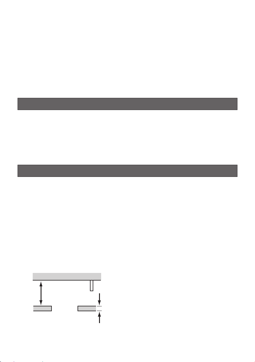
Installation area
• Consult the dealer about the installation area to select a strong ceiling area. Make sure that
the installation area is strong enough to hold the total weight of the camera assembly
(approx. 2.2 kg {4.85 lbs}) before installation.
• The installation area shall have 210 mm {8-1/4"} or more space behind the ceiling.
• The thickness of the ceiling board for installation can range from 9 to 40 mm {3/8" to 19/16"}.
210 mm {8-1/4"} or more
Ceiling board: from 9 to 40 mm {3/8" to 1-9/16"}
2
Page 3

Avoid installing in the following locations.
• Locations where it may get wet from rain or water splash
• Locations where a chemical agent is used such as a swimming pool (not only outdoor)
• Locations subject to steam and oil smoke such as a kitchen
• Locations where radiation or x-ray emissions are produced
• Locations where it may be damaged by briny air such as seashores
• Locations where the temperature is not within –10 °C to +50 °C {14 °F to 122 °F}.
• Locations subject to vibrations (This product is not designed for on-vehicle use.)
• Locations where the temperature may rapidly change such as the peripheral areas of the
air outlets of air conditioners or doors facing outside. (In case of installing the camera in
such locations, the dome cover may become foggy or condensation may be caused on the
cover.)
Tightening the screws and bolts
• The screws and bolts must be tightened with an appropriate tightening torque according to
the material and strength of the installation area. After tightening the screws or bolts, perform visual check to ensure tightening is enough and there is no backlash.
• Required pull-out capacity of a single screw/bolt is 196 N {44.1 lbf} or more.
Do not rub the edges of metal parts with your hand.
Failure to obsere this may cause injury.
Be sure to remove this apparatus if it is not in use.
Be sure to install the safety wire.
Use the specified camera only.
Failure to observe this may cause a fall of an inappropriate camera resulting in injury or accidents. Mount WV-NW484S on this bracket exclusively.
ENGLISH
Periodic inspections shall be conducted.
Rust on the metal parts or screws may cause a fall of the product resulting in injury.
Consult the dealer for the inspections.
3
Page 4

Major Operating Controls and Their Functions
Roof space
Safety wire angle (Accessory)
Safety wire (Accessory)
Roof space
WV-NW484S
* Read the Operating Instructions of
the camera as well.
Installations
Be sure to read "Precautions" on the page 2 before installation. The Operating Instructions of
the color CCTV camera, WV-NW484S, shall be read as well.
1. Put Template A (accessory) against the ceiling and make a hole.
q Make 4 holes of 12 mm {1/2"} in diameter.
w Remove the center part from the tem-
plate.
e Make a hole of 180 mm {7-1/16"} in diam-
eter.
Ceiling face
ø180 mm
{7-1/16"}
ø12 mm {1/2"}
(4 positions)
The ceiling holes are shown
in the drawing at right. →
Template A
4
Page 5
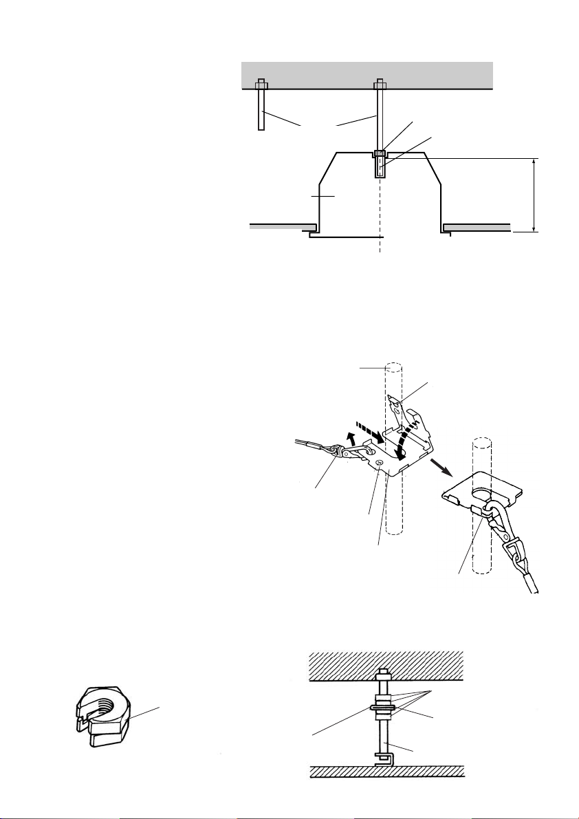
2. Install two anchor bolts (locally procured: M10 recommended) into the concrete ceiling.
q Install an anchor bolt in the
center of the hole made in the
step 1.
w Determine the anchor bolt
length by use of Template B
(accessory).
2nd Anchor bolt
(locally procured)
Anchor bolt
1st Anchor bolt (locally procured)
Nut (locally procured)
Determine the anchor
bolt length
e Use Template B (accessory) to
decide the nut position, and fix
it.
Template B
134 mm
{5-1/4"}
(Mount the nut so that the distance between the bottom surfaces of the nut and ceiling is
adjusted to 134 mm {5-1/4"}.)
Ceiling board
Install the anchor bolt in the center
of the hole
Note: If there is already an anchor bolt installed, the anchor bolt can be used as a 2nd anchor
bolt. Make sure that the distance between the 1st and 2nd anchor bolts is 1 000 mm {3.28'}
or less before use.
3. Mount the safety wire angle (accessory) on the 2nd anchor bolt and connect the safety wire (accessory) to the angle.
q Disconnect the safety wire from the safe-
ty wire angle.
w Engage the face marked q with the
anchor bolt.
Anchor bolt
w Insert
q Disconnect
Upper side
Mark w
e Bend
e Bend the face marked w.
r Connect the safety wire to the safety wire
angle again.
Safety wire
Mark q
Safety wire angle
Lower
side
r Connect
Note: To use the anchor bolt that was already installed, the use of 2 spacer nuts (locally pro-
cured) is helpful.
Spacer nuts
Spacer nuts
(locally procured)
Safety wire
Safety wire angle
Existing anchor bolt
5
Page 6

4. Connect this mount bracket to the tip
of the safety wire.
Roof space
Important: When securing this bracket
on the ceiling, make sure that the
four ceiling board fixing brackets are
open as shown in the following figure.
1st anchor bolt
Safety wire (Accessory)
Mount bracket
Insert the mount
bracket into the hole
5. Insert the 1st anchor bolt into the
mounting hole of the mount bracket.
Mounting hole
6. Secure the mount bracket to the ceiling board with the ceiling board fixing
screws (4 positions).
Turning the ceiling board fixing screws
clockwise provides ceiling board tightening between the bottom of the mount
bracket and ceiling board fixing bracket
resulting in mount bracket securing.
(Recommended tightening torque:
0.78N·m {0.58 lbf·ft})
Double nuts (locally
procured)
Ceiling
board fixing
screw
Ceiling board
Ceiling board
fixing bracket
Turn clockwise
7. Use double nuts (locally procured) to
secure the mount bracket after inserting the 1st anchor bolt.
8. Use the driver bit supplied with the
camera to remove the screws that
secure the camera enclosure and
remove the enclosure from the camera
main body.
Important: Refer to the Operating Inst-
ructions of the camera as well.
9. Perform camera wiring.
6
Page 7

10. Align the screw holes of the mount
bracket with the 4 mounting screws of
the camera main body and tighten
them.
(Recommended tightening torque:
0.78 N·m {0.58 lbf·ft})
Ceiling mount
bracket
Screw
holes
Screws of the main camera body
12. Mount the decorative cover on this
mount bracket.
• Mount the decorative cover on the camera mounting plate with engaging the
projections of the decorative cover with
the hooks for the decorative cover.
• Turn the decorative cover clockwise until
the cover clicks while pressing the cover
upward to lock the cover.
Hooks for the
decorative
cover
Projection
Note: The mount bracket supplied with
the camera is not used.
11. Mount the camera enclosure on the
camera main body.
7
Page 8

Specifications
Ambient temperature –10 °C to +50 °C {14 °F to 122 °F}
Dimensions 204.4 {8-1/16} mm in diameter x 143.4 {5-5/8} mm in height
Weight Approx. 705 g {1.55 lbs}
Finish Main body: Metal
Decorative cover: ABS resin with light silver coating
Standard Accessories
Instructions (this book) .................................. 1 pc.
The following are for installation.
Safety wire ..................................................... 1 pc.
Safety wire angle ........................................... 1 pc.
Template A .................................................... 1 pc.
Template B .................................................... 1 pc.
Decorative cover ........................................... 1 pc.
8
Page 9

TABLE DES MATIÈRES
Préface ......................................................................................................................................... 9
Mesures de précaution ................................................................................................................. 9
Principaux organes de commande et fonctions ......................................................................... 11
Installations ................................................................................................................................ 11
Caractéristiques techniques ....................................................................................................... 15
Accessoires standard ................................................................................................................. 15
Préface
Le modèle WV-Q169 est une platine de fixation encastrée en plafond exclusivement conçu
pour l'installation de la caméra vidéo couleur CCTV, WV-NW484S, au plafond. Cette platine de
fixation peut être utilisée pour une installation sur une surface possédant une faible résistance
à la traction telle qu'une plaque de plâtre dans un double plafond tandis que ce type encastré
offre l'avantage de rendre la partie visible de la caméra vidéo plus petite.
Mesures de précaution
Tous les travaux d’installation pour ce produit doivent être réalisés par des techniciens
qualifiés ou des installateurs de système confirmés.
Cet appareil est essentiellement conçu pour un usage sous abri.
Secteur d'installation
• Consulter le distributeur à propos de la surface d'installation afin de choisir une surface
d'installation au plafond suffisamment robuste. Il convient de s'assurer que la surface
d'installation est suffisamment robuste pour supporter le poids total de l'ensemble de
caméra vidéo (approximativement 2,2 kg {4,85 lbs}) avant l'installation.
• La surface d'installation doit pouvoir aménager 210 mm {8-1/4 po} ou davantage d'espace
derrière le plafond.
• L'épaisseur de panneau de plafond sélectionné pour faire l'installation peut se situer dans
les limites de 9 à 40 mm {3/8 po à 1-9/16 po}.
210 mm {8-1/4 po} ou
davantage
Panneau de plafond: De 9 à 40 mm {3/8 po à 1-9/16 po}
FRANÇAIS
9
Page 10

Éviter toute installation dans les emplacements suivants.
• Emplacements risquant d'être humides par la pluie ou des éclaboussures d'eau
• Emplacements où des agents chimiques sont utilisés comme dans le cas d'une piscine
(mais non limité à l'extérieur)
• Emplacements exposés à de la vapeur ou des émanations d'huile comme dans le cas
d'une cuisine
• Emplacements où il existe des radiations ou une émission de rayons X
• Emplacements où l'équipement risque d'être endommagé par de l'air salin comme au bord
de la mer
• Emplacements où la température ne se trouve pas dans les limites de –10 °C à +50 °C {14
°F to 122 °F}.
• Emplacements soumis à des vibrations (Cet appareil n'a pas été conçu pour être utilisé
dans un véhicule.)
• Emplacements où la température risque de changer rapidement comme cela se produit
dans les zones environnant les prises de refoulement d'air des climatiseurs ou des portes
dirigées vers l'extérieur. (Si toutefois la caméra vidéo est installée à ces emplacements, le
couvercle en dôme risque de s'embuer ou de la condensation peut se former sur le
couvercle.)
Serrage des vis de fixation et des boulons
• Les vis de fixation et les boulons d'installation doivent être serrés au couple de serrage
approprié en fonction des matériaux et de la résistance de la surface appelée à accueillir
la caméra vidéo. Une fois le serrage des vis de fixation ou des boulons terminé, procéder à
un examen visuel afin de s'assurer que le serrage est suffisant et qu'il n'y a pas de jeu.
• La force de traction d'une seule vis de fixation ou d'un seul boulon est de 196 N {44,1 lbf}
ou davantage.
Ne jamais frotter le bord des parties métalliques à mains nues.
Le fait de ne pas respecter cette précaution risque d'aboutir à des blessures.
Ne pas oublier de retirer cet appareil lorsqu'il n'est pas utilisé.
Ne pas oublier d'installer le câble de sécurité.
Se servir essentiellement de la caméra vidéo.
Le fait de ne pas observer ceci risque de provoquer une chute d'une caméra vidéo inadaptée
et par voie de conséquence de blesser quelqu'un voire engendrer des accidents. Installer le
modèle WV-NW484S exclusivement sur cette platine de fixation.
Des inspections périodiques doivent être effectuées.
Une formation de rouille sur les parties métalliques ou sur les vis de fixation peut engendrer
une chute de l'appareil et ceci peut entraîner des blessures.
Se mettre en rapport avec le distributeur en ce qui concerne les inspections à faire.
10
Page 11

Principaux organes de commande et fonctions
Espace de toit
Cornière de câble de sécurité
(accessoire)
Câble de sécurité (accessoire)
Espace de toit
WV-NW484S
* Lire également le manuel
d'utilisation de la caméra vidéo.
Installations
Il est indispensable de lire au préalable le passage intitulé "Mesures de précaution" de la page
16 avant d'effectuer l'installation. Il est également indispensable de lire le manuel d'utilisation
de la caméra vidéo couleur CCTV, WV-NW484S.
1. Placer le gabarit A (accessoire) contre la surface au plafond et percer une ouverture.
q Percer 4 ouvertures de 12 mm {1/2 po}
de diamètre.
w Retirer la partie centrale du gabarit.
e Percer une ouverture de 180 mm
{7-1/16 po} de diamètre.
Les ouvertures percées au
Surface du plafond
ø180 mm
{7-1/16 po}
ø12 mm {1/2 po}
(4 endroits)
plafond sont indiquées sur
le schéma ci-contre à
droite. →
Gabarit A
11
Page 12

2. Fixer deux boulons d'ancrage (à se procurer localement: M10 recommandé) dans le
plafond en béton.
q Fixer un boulon d'ancrage au
centre de l'ouverture faite au
cours de l'étape 1.
w Déterminer la longueur du
boulon d'ancrage en utilisant le
gabarit B (accessoire).
e Se servir du gabarit B
2ème boulon d'ancrage
(
à se procurer localement)
Boulon d'ancrage
1er boulon d'ancrage
(à se procurer localement)
Écrou (à se procurer localement)
Déterminer la longueur
du boulon d'ancrage
(accessoire) pour décider de la
position de l'écrou de fixation
et le fixer.
(Fixer l'écrou de fixation de
Gabarit B
134 mm
{5-1/4 po}
telle manière que la distance
entre les surfaces de base de
l'écrou de fixation et plafond
soient ajustées sur 134 mm
{5-1/4 po}.)
Panneau de
plafond
Fixer un boulon d'ancrage au
centre de l'ouverture
Remarque: Si un boulon d'ancrage est déjà installé, le boulon d'ancrage peut être utilisé
comme second boulon d'ancrage. S'assurer que la distance entre le 1er et le 2ème
boulons d'ancrage est de 1 000 mm {3,28 pd.} ou inférieure avant de l'utiliser.
3. Installer la cornière du câble de sécurité (accessoire) sur le 2ème boulon d'ancrage et
raccorder le câble de sécurité
(accessoire) à la cornière.
q Débrancher le câble de sécurité de la
cornière de câble de sécurité.
w Engager la surface identifiée par q sur
le boulon d'ancrage.
e Replier la surface identifiée par w.
Boulon d'ancrage
w Introduire
q Débrancher
Côté supérieur
Repère w
e Plier
r Raccorder à nouveau le câble de
sécurité à la cornière du câble de
sécurité.
Câble de sécurité
Repère q
Cornière de câble de
sécurité
Côté
inférieur
r Raccorder
Remarque: Il est utile de se servir de 2 écrous d'entretoise (à se procurer localement) pour
utiliser le boulon d'ancrage qui était déjà en place.
Écrous d'entretoise
(à se procurer localement)
Câble de
sécurité
Écrous d'entretoise
Cornière de câble de
sécurité
Boulon d'ancrage déjà en
place
12
Page 13

4. Relier cette platine de fixation à
l'extrémité du câble de sécurité.
Espace de toit
Introduire la platine
Câble de sécurité
(accessoire)
Platine de fixation
de fixation dans
l'ouverture
Important: Lorsque cette platine de fixation
est fixée au plafond, il convient de
s'assurer que les quatre platines de
fixation de panneau de plafond sont
ouvertes comme cela est représenté sur
la figure.
1er boulon d'ancrage
Double écrous
de fixation
(
à se procurer
localement)
Vis de fixation
de panneau
de plafond
5. Introduire le boulon du 1er ancrage
dans l'ouverture d'installation de la
platine de fixation.
Mounting hole
6. Fixer solidement la platine de fixation
au panneau de plafond avec les vis de
fixation de panneau de plafond
(4 endroits).
Le fait de tourner les vis de fixation de
panneau de plafond dans le sens des
aiguilles d'une montre a pour effet de
serrer le panneau de plafond entre la
base de la platine de fixation et la platine
de fixation de panneau de plafond, ce
qui offre une fixation robuste de la platine
de fixation.
(Couple de serrage recommandé:
0,78 N·m {0,58 lbf·ft})
Platine de fixation
de panneau de
Panneau de
plafond
plafond
Faire tourner dans le sens
des aiguilles d'une montre
7. Se servir de double écrous de fixation
(à se procurer localement) pour fixer la
platine de fixation d'installation de
caméra vidéo après avoir introduit le
1er boulon d'ancrage.
8. Se servir du foret de tournevis fourni
avec la caméra vidéo pour retirer les
vis de fixation qui retiennent
l'enveloppe de caméra vidéo et
séparer l'enveloppe du bloc principal
de la caméra vidéo.
Important: Se référer également au
manuel d'utilisation de la caméra
vidéo.
9. Réalisation des câblage de la caméra
vidéo.
13
Page 14

10. Aligner les trous de vis de fixation de
la platine de fixation d'installation
avec les 4 vis de fixation d'installation
du bloc principal de la caméra vidéo et
les serrer.
(Couple de serrage recommandé:
0,78 N·m {0,58 lbf·ft})
Platine de fixation
pour une installation au plafond
12. Monter le couvercle décoratif sur cette
platine de fixation.
• Monter le couvercle décoratif sur la
plaque d'installation de caméra vidéo en
engageant les parties saillantes du
couvercle décoratif dans les crochets
pour le couvercle décoratif.
• Faire tourner le couvercle décoratif dans
le sens des aiguilles d'une montre
jusqu'à ce que le couvercle émette un
déclic tout en le repoussant vers le haut
afin de verrouiller le couvercle.
Trous de vis
de fixation
Vis de fixation de bloc principal de caméra vidéo
Remarque: La platine de fixation d'in-
stallation de caméra vidéo fournit
avec la caméra vidéo n'est pas
utilisée.
11. Installer l'enveloppe de caméra vidéo
sur le bloc principal de caméra vidéo.
Crochets pour
couvercle
décoratif
Partie saillante
14
Page 15

Caractéristiques techniques
Température ambiante –10 °C à +50 °C {14 °F à 122 °F}
Dimensions 204,4 mm {8-1/16 po} de diamètre x 143,4 mm {5-5/8 po} de
Poids Approx. 705 g {1,55 lbs}
Finition Boîtier principal: Métal
haut
Couvercle décoratif: Résine ABS avec un revêtement argent
clair
Accessoires standard
Manuel d'utilisation (cette brochure) ............. 1 él.
Les éléments suivants sont utilisés pour l'installation.
Câble de sécurité .......................................... 1 él.
Cornière de câble de sécurité ....................... 1 él.
Gabarit A ....................................................... 1 él.
Gabarit B ....................................................... 1 él.
Couvercle décoratif ....................................... 1 él.
15
Page 16

Panasonic System Solutions Company,
Unit Company of Panasonic Corporation of North America
Security Systems
www.panasonic.com/security
For customer support, call 1.877.733.3689
Executive Office: Three Panasonic Way 2H-2, Secaucus, New Jersey 07094
Zone Office
Eastern: Three Panasonic Way, Secaucus, New Jersey 07094
Central: 1707 N. Randal Road, Elgin, IL 60123
Southern: 1225 Northbrook Parkway, Suwanee, GA 30024
Western: 6550 Katella Ave., Cypress, CA 90630
Panasonic Canada Inc.
5770 Ambler Drive,Mississauga,
Ontario, L4W 2T3 Canada (905)624-5010
http://www.panasonic.ca
Panasonic Sales Company
Division of Panasonic Puerto Rico Inc.
San Gabriel Industrial Park 65th Infantry Ave. KM. 9.5 Carolina
P.R. 00985(809)750-4300
© 2007 Matsushita Electric Industrial Co., Ltd. All Rights Reserved.
NM0407-0 3TR005064AAA Imprimé au Japon
Printed in Japan
 Loading...