

Panasonic WV-CZ352 User Manual
Colour CCTV Camera
Operating Instructions
Model No. WV-CZ352
ENGLISH
DEUTSCH
FRANÇAIS
ESPAÑOL
Before attempting to connect or operate this product,
please read these instructions carefully and save this manual for future use.
ITALIANO
РУССКИЙ
ENGLISH VERSION
Please read the label of the bottom before
connecting or operating this camera.
CAUTION
RISK OF ELECTRIC SHOCK
DO NOT OPEN
CAUTION: TO REDUCE THE RISK OF ELECTRIC SHOCK,
DO NOT REMOVE COVER (OR BACK).
NO USER-SERVICEABLE PARTS INSIDE.
REFER SERVICING TO QUALIFIED SERVICE PERSONNEL.
We declare under our sole responsibility that the product
to which this declaration relates is in conformity with the
standards or other normative documents following the
provisions of Directives EEC/73/23 and EEC/89/336.
Wij verklaren als enige aansprakelijke, dat het product waarop
deze verklaring betrekking heeft, voldoet aan de volgende normen of andere normatieve documenten, overeenkomstig de
bepalingen van Richtlijnen 73/23/EEC en 89/336/EEC.
Vi erklærer os eneansvarlige for, at dette produkt, som
denne deklaration omhandler, er i overensstemmelse med
standarder eller andre normative dokumenter i følge
bestemmelserne i direktivene 73/23/EEC og 89/336/EEC.
Vi deklarerar härmed värt fulla ansvar för att den produkt till
vilken denna deklaration hänvisar är i överensstämmelse
med standarddokument, eller andra normativa dokument
som framstölls i EEC-direktiv nr. 73/23 och 89/336.
Ilmoitamme yksinomaisella vastuullamme, että tuote,
jota tämä ilmoitus koskee, noudattaa seuraavia standardeja tai muita ohjeellisia asiakirjoja, jotka noudattavat direktiivien 73/23/EEC ja 89/336/EEC säädöksiä.
The lightning flash with arrowhead symbol, within an equilateral triangle, is intended to alert
the user to the presence of unin-
Vi erklærer oss alene ansvarlige for at produktet som denne
erklæringen gjelder for, er i overensstemmelse med følgende
normer eller andre normgivende dokumenter som følger
bestemmelsene i direktivene 73/23/ EEC og 89/336/EEC.
sulated “dangerous voltage”
within the product's enclosere
that may be of sufficient magnitude to constitute a risk of electric shock to the human body.
The exclamation point within
an equilateral triangle is intended to alert the user to the presence of important operating
and maintenance (servicing)
instructions in the literature
accompanying the appliance.
The serial number of this product may
be found on the rear of the unit. You
should note the serial number of this
unit in the space provided and retain this
book as a permanent record of your purchase to aid identification in the event of
theft.
Model No.
Serial No.
Warning:
To prevent fire or electric shock hazard, do not expose this appliance to rain or moisture.
The apparatus shall not be exposed to dripping or splashing and that no objects filled
with liquids, such as vases, shall be placed on the apparatus.
2

IMPORTANT SAFETY INSTRUCTIONS
1) Read these instructions.
2) Keep these instructions.
3) Heed all warnings.
4) Follow all instructions.
5) Do not use this apparatus near water.
6) Clean only with dry cloth.
7) Do not block any ventilation openings. Install in accordance with the manufacturer's
instructions.
8) Do not use near any heat sources such as radiators, heat registers, stoves, or other apparatus (including amplifiers) that produce heat.
9) Do not defeat the safety purpose of the polarized or grounding-type plug. A polarized
plug has two blades with one wider than the other. A grounding-type plug has two blades
and a third grounding prong. The wide blade or the third prong are provided for your
safety. If the provided plug does not fit into your outlet, consult an electrician for replacement of the obsolete outlet.
10) Protect the power cord from being walked on or pinched particularly at plugs, convenience receptacles and the points where they exit from the apparatus.
11) Only use attachments/accessories specified by the manufacturer.
12) Use only with the cart, stand, tripod, bracket, or table specified by the manufacturer, or
sold with the apparatus. When a cart is used, use caution when moving the cart/apparatus combination to avoid injury from tip-overs.
ENGLISH
S3125A
13) Unplug this apparatus during lightning storms or when unused for long periods of time.
14) Refer all servicing to qualified service personnel. Servicing is required when the apparatus has been damaged in any way, such as power-supply cord or plug is damaged, liquid
has been spilled or objects fallen into the apparatus, the apparatus has been exposed to
rain or moisture, does not operate normally, or has been dropped.
3

LIMITATION OF LIABILITY
THIS PUBLICATION IS PROVIDED "AS IS" WITHOUT WARRANTY OF ANY KIND, EITHER
EXPRESS OR IMPLIED, INCLUDING BUT NOT LIMITED TO, THE IMPLIED WARRANTIES OF
MERCHANTABILITY, FITNESS FOR ANY PARTICULAR PURPOSE, OR NON-INFRINGEMENT
OF THE THIRD PARTY’S RIGHT.
THIS PUBLICATION COULD INCLUDE TECHNICAL INACCURACIES OR TYPOGRAPHICAL
ERRORS. CHANGES ARE ADDED TO THE INFORMATION HEREIN, AT ANY TIME, FOR THE
IMPROVEMENTS OF THIS PUBLICATION AND/OR THE CORRESPONDING PRODUCT(S).
DISCLAIMER OF WARRANTY
IN NO EVENT SHALL MATSUSHITA ELECTRIC INDUSTRIAL CO., LTD. BE LIABLE TO
ANY PARTY OR REASONABLE MAINTENANCE OF THE PRODUCT, FOR THE CASES,
INCLUDING BUT NOT LIMITED TO BELOW:
(1) ANY DAMAGE AND LOSS, INCLUDING WITHOUT LIMITATION,DIRECT OR INDIRECT,
SPECIAL, CONSEQUENTIAL OR EXEMPLARY, ARISING OUT OF OR RELATING TO
THE PRODUCT;
(2) PERSONAL INJURY OR ANY DAMAGE CAUSED BY INAPPROPRIATE USE OR NEG-
LIGENT OPERATION OF THE USER;
(3) UNAUTHORIZED DISASSEMBLE, REPAIR OR MODIFICATION OF THE PRODUCT BY
THE USER;
(4) ANY PROBLEM, CONSEQUENTIAL INCONVENIENCE, OR LOSS OR DAMAGE, ARIS-
ING OUT OF THE SYSTEM COMBINED BY THE DEVICES OF THIRD PARTY;
(5) INCONVENIENCE OR ANY LOSS ARISING WHEN IMAGES ARE NOT DISPLAYED,
DUE TO ANY REASON OR CAUSE INCLUDING ANY FAILURE OR PROBLEM OF THE
PRODUCT;
(6) ANY CLAIM OR ACTION FOR DAMAGES, BROUGHT BY ANY PERSON OR ORGANI-
ZATION BEING PHOTOGENIC SUBJECT, DUE TO VIOLATION OF PRIVACY WITH
THE RESULT OF THAT SURVEILLANCE-CAMERAS PICTURE, INCLUDING SAVED
DATA, FOR SOME REASON, BECOMES PUBLIC OR IS USED FOR THE PURPOSE
OTHER THAN SURVEILLANCE.
4

CONTENTS
IMPORTANT SAFETY INSTRUCTIONS . . . . . . . . . . . . . . . . . . . . . . . . . . . . . . . . . . . . . . . . . .3
LIMITATION OF LIABILITY . . . . . . . . . . . . . . . . . . . . . . . . . . . . . . . . . . . . . . . . . . . . . . . . . . . 4
DISCLAIMER OF WARRANTY . . . . . . . . . . . . . . . . . . . . . . . . . . . . . . . . . . . . . . . . . . . . . . . . .4
CONTENTS . . . . . . . . . . . . . . . . . . . . . . . . . . . . . . . . . . . . . . . . . . . . . . . . . . . . . . . . . . . . . . . .5
PREFACE . . . . . . . . . . . . . . . . . . . . . . . . . . . . . . . . . . . . . . . . . . . . . . . . . . . . . . . . . . . . . . . . . .6
FEATURES . . . . . . . . . . . . . . . . . . . . . . . . . . . . . . . . . . . . . . . . . . . . . . . . . . . . . . . . . . . . . . . . .6
PRECAUTIONS . . . . . . . . . . . . . . . . . . . . . . . . . . . . . . . . . . . . . . . . . . . . . . . . . . . . . . . . . . . . .7
MAJOR OPERATING CONSTRUCTION AND THEIR FUNCTIONS . . . . . . . . . . . . . . . . . . . .9
CAMERA INSTALLATION . . . . . . . . . . . . . . . . . . . . . . . . . . . . . . . . . . . . . . . . . . . . . . . . . . . .10
CONNECTIONS . . . . . . . . . . . . . . . . . . . . . . . . . . . . . . . . . . . . . . . . . . . . . . . . . . . . . . . . . . . .10
SETTING PROCEDURE . . . . . . . . . . . . . . . . . . . . . . . . . . . . . . . . . . . . . . . . . . . . . . . . . . . . .14
■ Camera Setting . . . . . . . . . . . . . . . . . . . . . . . . . . . . . . . . . . . . . . . . . . . . . . . . . . . . . . .15
■ Preset Position Setting . . . . . . . . . . . . . . . . . . . . . . . . . . . . . . . . . . . . . . . . . . . . . . . . . .23
■ Special Setting . . . . . . . . . . . . . . . . . . . . . . . . . . . . . . . . . . . . . . . . . . . . . . . . . . . . . . . .26
■ Communication Setting . . . . . . . . . . . . . . . . . . . . . . . . . . . . . . . . . . . . . . . . . . . . . . . . .27
■ Password Lock Setting . . . . . . . . . . . . . . . . . . . . . . . . . . . . . . . . . . . . . . . . . . . . . . . . . .28
SPECIFICATIONS . . . . . . . . . . . . . . . . . . . . . . . . . . . . . . . . . . . . . . . . . . . . . . . . . . . . . . . . . .30
STANDARD ACCESSORIES . . . . . . . . . . . . . . . . . . . . . . . . . . . . . . . . . . . . . . . . . . . . . . . . . .30
5

PREFACE
Panasonic presents highly advanced CCTV technology that meets the demands of new
and ever-changing applications.
This high-performance colour camera is as a video surveillance device.
The camera incorporates Super Digital Signal Processor, 22x zoom lens and RS485 in a
compact enclosure.
A newly developed 1/4-type {1/4"} CCD is employed for use under extremely low light
conditions:
0.06 lx for Black & White and 1 lx for colour.
It also assures clear display of pictures in which bright and dark objects coexist without
mutual interference thanks to Super DSP. Setup menus allow the camera to fulfill
surveillance tasks by such means as Motion Detector, and Privacy Zones.
FEATURES
●
High quality picture of 752 x 582 pixels
●
Minimum illumination of 1 lx for colour
●
Minimum illumination of 0.06 lx for Day/Night mode
●
Privacy zone feature enables users to veil unwanted zones.
●
Protocol adaptability to Panasonic's protocol
●
Auto Day/Night mode enables the camera to switch between C/L and B/W in response
to input lights
●
Reduction in minimum illuminance to 0.03 lx in the Day/Night mode thanks to PIX
SENS UP
●
Built-in digital motion detector and alarm outputs
●
Up to 64 preset positions
●
Sync selectable from among internal and VD2
●
Automatic gain control circuit
●
Image hold
●
Digital noise reduction effect
●
Setting change executable only by authorized personnel thanks to the password lock
function
●
Enhanced horizontal resolution by resolution setting
6

PRECAUTIONS
1. Do not attempt to disassemble the camera.
To prevent electric shock, do not remove screws or covers.
There are no user-serviceable parts inside.
Ask qualified service personnel for servicing.
2. Handle the camera with care.
Do not misuse the camera. Avoid striking, shaking, etc.
The camera could be damaged by improper handling or storage.
3. Do not expose the camera to rain or moisture, nor try to operate it in
wet areas.
This product is designed for indoor use or locations where it is protected from rain and
moisture.
Turn the power off immediately and ask qualified service personnel for servicing.
Moisture can damage the camera and also create the danger of electric shock.
4. Do not use strong or abrasive detergents when cleaning the camera
body.
Use a dry cloth to clean the camera when it is dirty.
When the dirt is hard to remove, use a mild detergent and wipe gently.
Afterwards, wipe off the remaining detergent with a dry cloth.
5. Never aim the camera at the sun.
Whether or not the camera is in use, never aim it at the sun or other extremely bright
objects. Otherwise, blooming or smear may be caused.
6. Never aim the camera at strong light sources for an extended period
of time.
A light source such as a spot light causes burn-in on the display screen. Failure to
observe this may cause the image to become discoloured due to deterioration of the
colour filter in the CCD.
7. Do not operate the camera beyond the specified temperature,
humidity or power source ratings.
Do not use the camera in an extreme environment where high temperature or high
humidity exists. Do not place the camera near heat sources such as radiators, stoves
or other units that produce heat.
Use the camera under conditions where temperature is between -10 ˚C - +50 ˚C {14 ˚F
- 122 ˚F}, preferably +40 ˚C {104 ˚F}, and humidity is below 90 %.
The input power source is 9 V DC - 15 V DC.
7

8. Do not install the camera near the air outlet of an air conditioner.
The lens may become cloudy due to condensation if the camera is used under the following conditions.
●
Rapid temperature fluctuations by switching the air conditioner on and off.
●
Rapid temperature fluctuations due to frequent door opening and closing.
●
Do not use in an environment where eyeglasses become foggy.
●
Do not use in a room filled with cigarette smoke or dust.
If the lens becomes cloudy due to condensation, wipe all moist surfaces with a soft
cloth.
9. Consumables.
Parts having contacts such as the lens-drive motors, inside the camera are subject to
wear with time. Please ask the nearest service centre about replacement and maintenance of such parts.
8
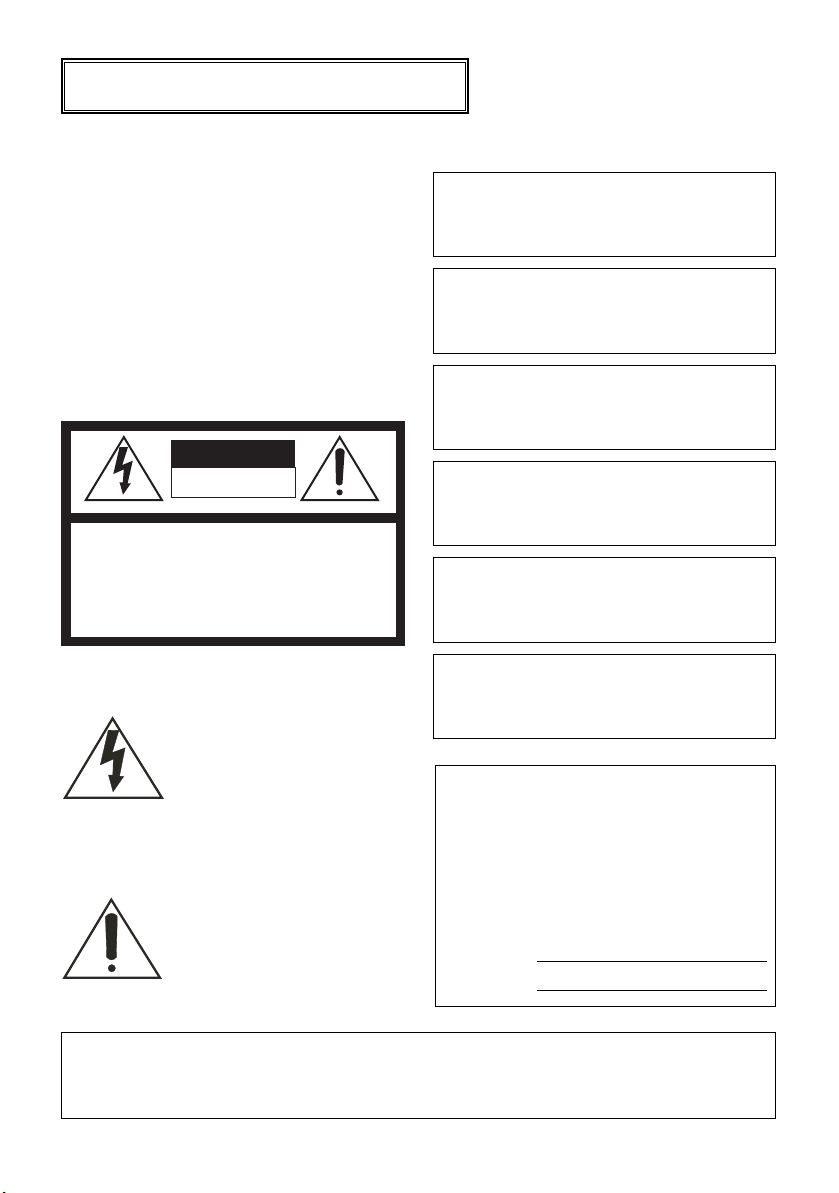
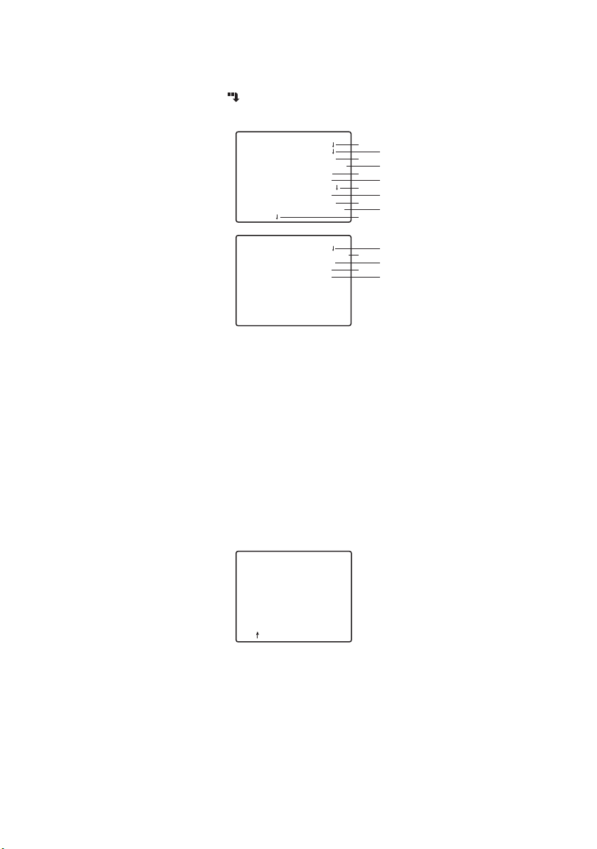
MAJOR OPERATING CONSTRUCTION AND THEIR FUNCTIONS
9
1
1 Camera Mounting Adapter
Mounts the camera onto a mounting
bracket.
2 DC Input Terminal
Supply 12 V DC from an external power
source.
3 Power Indicator (POWER)
4 Set Button((SET) AF/MENU)
Activates an item selected in the SETUP
menu.
This button is used to activate the Auto
Focus function.
5 Left Button((LEFT) NEAR)
Moves the cursor to the left, selects the
mode and adjusts some levels.
Moves the focus to NEAR.
6 Up Button((UP) TELE)
Moves the cursor upward and selects
items.
Moves the zoom to TELE.
7 Right Button((RIGHT) FAR)
Moves the cursor to the right, selects the
mode and adjusts some levels.
Moves the focus to FAR.
8 Down Button((DOWN) WIDE)
Moves the cursor downward and selects
items.
3
2
1
5
4
Moves the ZOOM to WIDE.
9 Video Output Connector
Connects the VIDEO IN connector of the
monitor.
0 Lens Control Terminal
Controls the Zoom, Focus and Iris of the
lens.
- Alarm Output Terminal (ALM OUT)
Connects to the alarm input connector
(terminal) of an external device. When
the camera detects motion, the alarm
output signal is supplied to the connected
external device(Open collector output: 16
V DC, 100 mA max).
= Day/Night Input Terminal (D/N IN)
This terminal is used for connecting the
camera to an external day/night detecting
sensor.
~ A/D Control Input Terminal (A/D IN)
Controls the camera by the voltage.
! RS485 Data In/Output Terminal
These terminals are used for RS485 site
communication. Connect RS485 cables
to these terminals.
@ RS485 2Wire/4Wire-Term Select
Switch
Terminates of the RS485 and selects
either half duplex or full duplex.
0
=
~
!
@
6
7
8
9
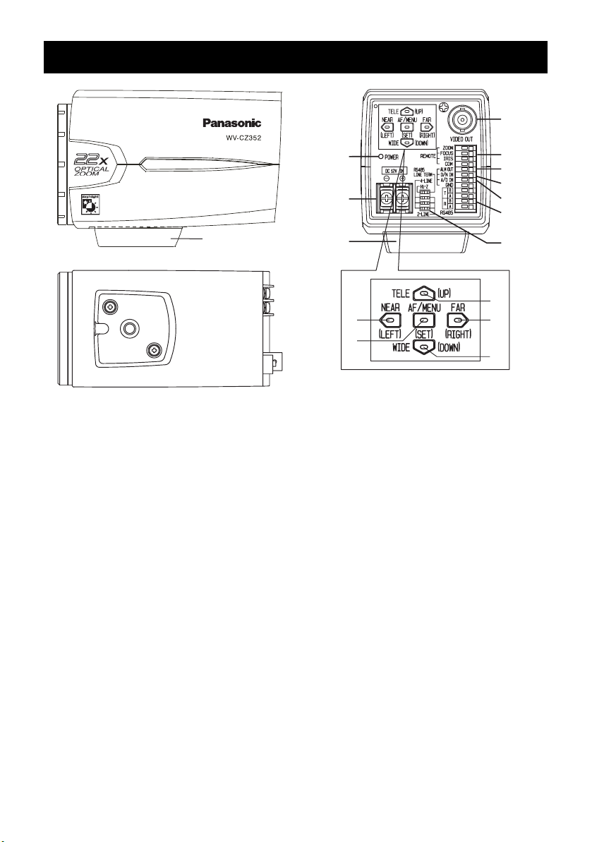
CAMERA INSTALLATION
●
Mounting from the top
Remove the Camera Mounting Adapter from the bottom of the camera by removing the
two fixing screws. Attach the Camera Mounting Adapter to the top as shown in the figure,
then mount the camera on the mounting bracket.
Cautions:
●
Be sure to use two original fixing screws for the
mounting adapter.
●
Longer screws may damage the inner components. Or shorter screws may cause the camera
drop.
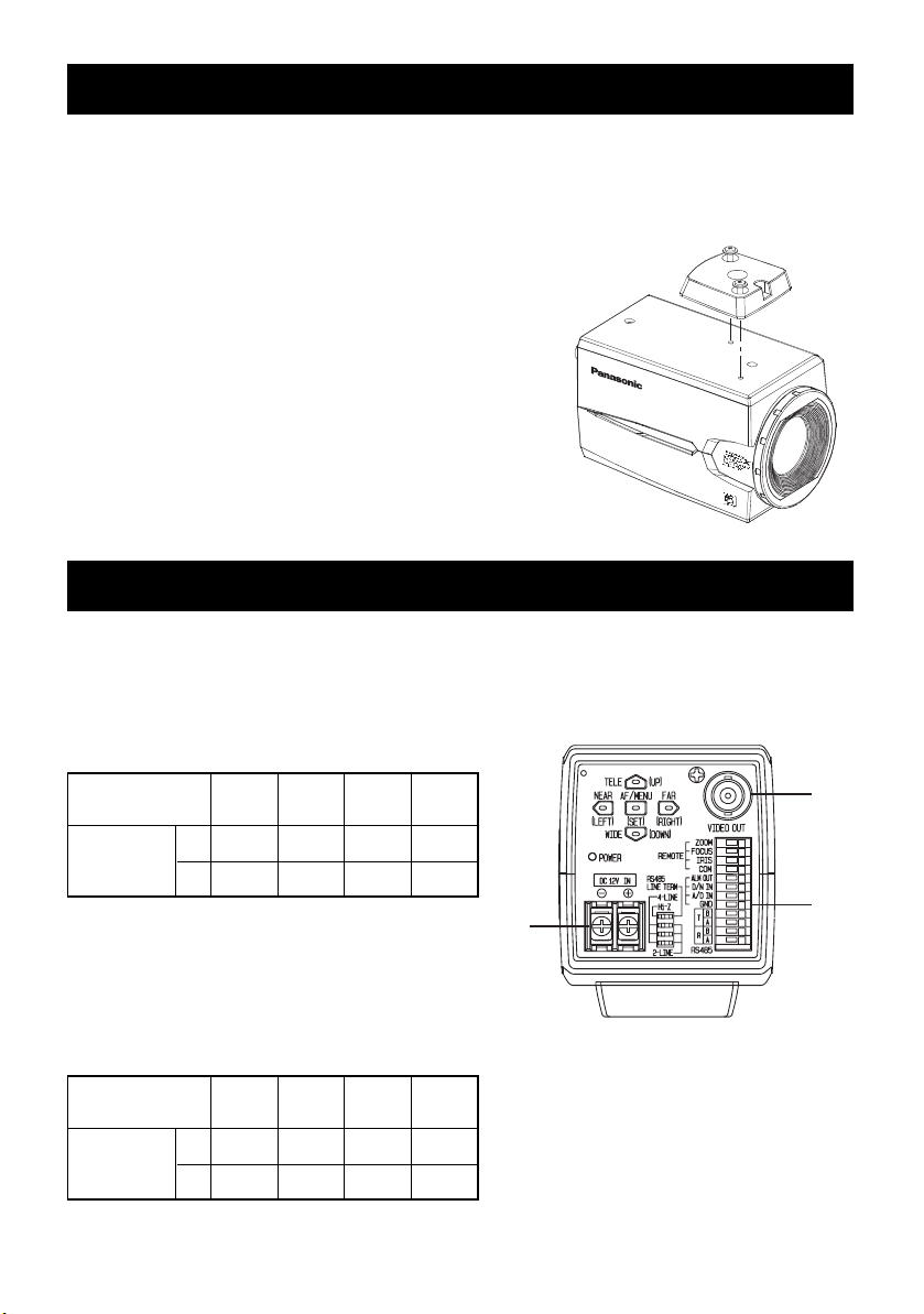
CONNECTIONS
Caution: The following connections should be made by qualified service personnel or
system installers in accordance with all local codes.
1 Video Cable
Type of coaxial
cable
Recommended maximum cable length
(m)
(ft)
RG-59/U
(3C-2V)
250 500 600 800
825 1 650 1 980 2 640
RG-6U
5
C-2V)
(
RG-
7
(
11
C-2V)
/U
2 Power Cable
Connect the power cord to the DC12 V IN
terminal.
Resistance of copper wire [at 20 ˚C {68 ˚F}]
Copper wire size
(AWG)
Resistance
#24
#22
2
(0.22 mm
)
(0.33 mm2)
0.078 0.050 0.03 0.018
Ω/m
Ω/
ft
0.026 0.017 0.010 0.006
(0.52 mm2)
#20
10
RG-
15
10
C-2V)
(
#18
(0.83 mm2)
/U
2
1
3
●
Calculation of the relation among the cable
length, resistance, and power supply:
9V DC ≤ VA - 2(R x 0.24 x L) ≤ 15V DC
L: Cable length (m)
R: Resistance of copper wire (Ω/m)
VA: DC output voltage of power supply unit
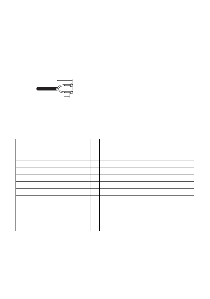
Cable Preparation
Power cable (with sealing at the side of the
camera)
20 mm {0.79"} or less
Cautions:
●
Shrinking the cable-entry seal is a onetime procedure. Do not shrink the cableentry seal until it has been ascertained
that the unit is functioning.
●
To prevent fire or electric shock hazard,
use a UL listed cable (WV-1, style 1007)
for the DC 12 V IN terminal.
●
Do not mistake “+” and “-” when connecting the power cable to the DC 12 V IN
terminal of the camera. It may cause
trouble.
●
This is not mobile equipment. Never feed
the power from a battery source.
Seal here
●
Connect to 12 V DC class 2 power supply
only.
3 Control Terminals
This is a cameral control terminal. Make correct connections according to the respective specifications.
NAME
1IN
ZOOM (TELE: +, WIDE: -) TELE (+3 V~+15 V) WIDE (-3 V~-15 V)
FOCUS (NEAR: +, FAR: -)
2
IRIS (OPEN: +, CLOSE:-)
3
COM (For ZOOM, FOCUS, IRIS)
4
ALARM
5
DAY/NIGHT
6
A/D
7
GND (For ALARM, DAY/NIGHT, A/D)
8
RS485 T (B)
9
RS485 T (A)
10
RS485 R (B)
11
RS485 R (A)
12
NOTICEI/O
IN
NEAR (+3 V~+15 V) FAR (-3 V~-15 V)
IN
OPEN (+3 V~+15 V) CLOSE (-3 V~-15 V)
Open collector-output max.16 V DC 100 mA OFF (OPEN)/ON (0 V)
OUT
Pulled up to 5.0 V DC OFF (open or 4 V DC-5 V DC)/ON (0V 0.2 mA)
IN
Pulled up to 3.3 V with 47 kΩ.
IN
OUT
OUT
IN
IN
Lens Control Terminals
Control is possible from external equipment by changing ZOOM, FOCUS, and IRIS to “+”
or “-”.
11
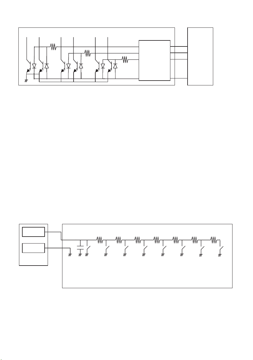
Internal Connection Diagram
3.6 kΩ
3.6 kΩ
3.6 kΩ
ZOOM
FOCUS
IRIS
external
controller
etc.
COM
*
If you use a lens control terminal, you should not use GND but the COM terminal.
*
The COM terminal is used in common with ZOOM, FOCUS, and IRIS.
*
To change the polarity of “+” or “-”, make a changeover with the SETUP MENU of ZOOM
INVERSE or FOCUS INVERSE.
Alarm Output Terminal
Connect an external device such as a buzzer or lamp to the ALM OUT terminal.
DAY/NIGHT Input Terminal
Connect an external sensor to the DAY/NIGHT IN terminal.
Notes:
●
Use a relay unit if the voltage or current of the connected device exceeds the rating.
●
To validate the Day/Night function, set BW mode to EXT on the menu.
A/D Control Input Terminal
This camera can be controlled through the A/D IN terminal by means of an analog voltage or a
resistance shunt circuit specified below.
12
A/D IN
GND
0.1 µF 6.8 kΩ 8.2 kΩ 12 kΩ 18 kΩ 33 kΩ 68 kΩ 180 kΩ
TELE WIDE NEAR CLOSE AF DAY/NIGHT
FAR OPEN
ACTION
1
2
3
4
5
TELE
WIDE
NEAR
FAR
OPEN
V-SW(V) ACTION V-SW(V)
0.4
0.8
1.2
1.6
0
6
7
8
9
CLOSE
AF
DAY/NIGHT
NONE
2.0
2.4
2.8
3.3
* A/D IN terminal is pulled up to 3.3 V with 47 kΩ.internally.
* Since the A/D IN terminal can be affected by noise, the cable length should be limited to
within 1.5 meters.
Note: The GND terminal comes in only one. If multiple GND lines are required, branches
should be made outside the equipment.
RS485 Setting
Follow the procedures as below.
1. Set RS485 2Wire/4Wire-term select switch to RS485 data input/output terminal for the furthermost camera from the RS232C/RS485 converter and Hi-Z for the other camera.
Switch Position
SW1
Right
Left
Function
Te rmination ON
Hi-Z
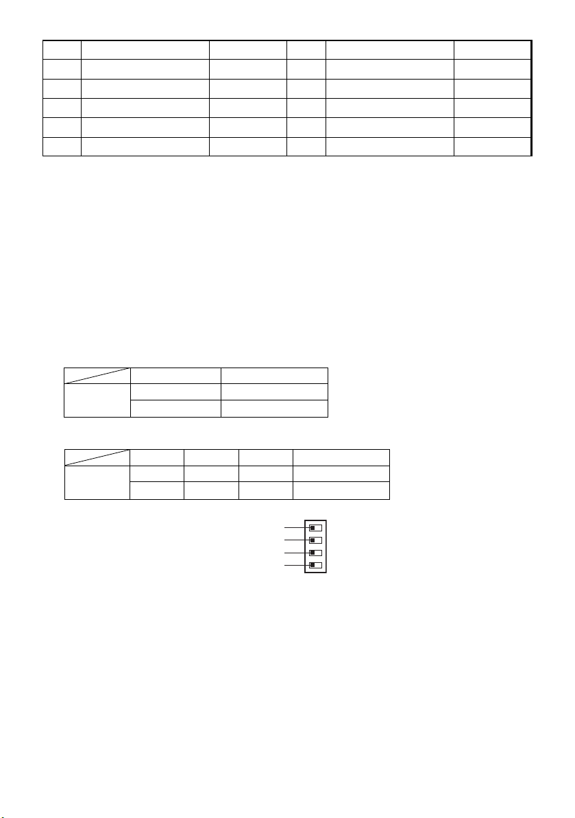
2. Select protocol by sliding triple full duplex/half duplex selection switches simultaneously.
Switch Position
SW2
Right
Left
SW3
Right
Left
SW4
Right
Left
Switch 1
Switch 2
Switch 3
Switch 4
Function
Half duplex (2-line)
Full duplex (4-line)
13
Notes:
T (B)
T (A)
R (B)
R (A)
T (B)
T (A)
R (B)
R (A)
●
Daisy chain connection is not available for full duplex.
●
With a distant unit, communication may fail to be maintained because of a GND potential
difference. In such a case, use the GND circuit in common, or use an RS isolator or the like
available on general market.
RS485 Terminals
Control data is transmitted and received to and from other peripherals.
Notes:
●
Two twisted pairs cable
●
Low impedance
●
Wire gauge size is thicker than AWG#22 (0.33 mm2)
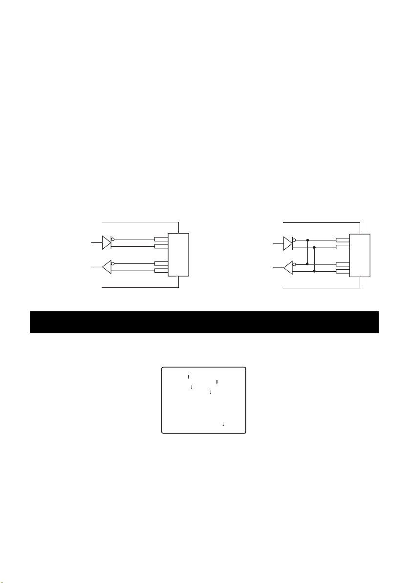
●
Internal Diagram
<Full duplex> <Half duplex>
Data Transmission
Data Reception
Data Transmission
Data Reception
SETTING PROCEDURE
Hold down the SET button to open the SETUP menu.
** WV-CZ352 SETUP **
CAMERA
PRESET POSITION
SPECIAL
COMMUNICATION
PASSWORD LOCK OFF
END
When the SET button is pressed for each item, each setting can be made.
Setting can not be made if ON setting has been made for PASSWORD LOCK. Setting should
be carried out after PASSWORD LOCK has been canceled.
Refer to Page 29 in regard to the method of PASSWORD LOCK canceling.
●
To close the menu from Camera Setup buttons, select END.
●
If no operation is performed for 6 minutes, the menu becomes automatically closed.
14
■ Camera Setting
●
To Display the Camera Setup Menu
Move the cursor to CAMERA , and press the SET button. The CAMERA SETUP menu
appears.
** CAMERA SETUP ** 1/2
CAMERA ID OFF
ALC/MANUAL ALC
SHUTTER AUTO
AGC ON(MID)
SENS UP OFF
SYNC INT
WHITE BAL ATW1
MOTION DET OFF
DNR LOW2
RESOLUTION NORMAL
BW MODE
** CAMERA SETUP ** 2/2
PRIVACY ZONE OFF
AF MODE STOP AF
ZOOM LIMIT x 22
UPSIDE-DOWN OFF
MIRROR OFF
RET TOP END
1 Camera Identification Setting (CAMERA ID)
You can use the camera identification (CAMERA ID) to assign a name to the camera.
The camera ID consists of up to 16 alphanumeric characters.
The camera ID display can be switched on or off on the monitor screen.
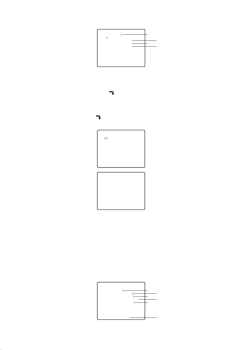
To edit the CAMERA ID
1. Move the cursor to CAMERA ID.
2. The cursor on the letter “0” is highlighted.
3. Move the cursor to the character you want to edit.
4. After selecting the character, press the SET button.
The selected character appears in the editing area.
5. Repeat the steps above until all characters are edited.
q
w
e
r
t
y
u
i
o
!0
!1
!2
!3
!4
!5
!6
CAMERA ID
0123456789
ABCDEFGHIJKLM
NOPQRSTUVWXYZ
().,'":;&#!?=
+-*/%$ДЬЦЖСЕ
SPACE
POSI RET RESET
................
To enter a blank space in the CAMERA ID
Move the cursor to SPACE and press the SET button.
To erase all characters in the editing area
Move the cursor to RESET and press the SET button. All characters in the editing area
disappear.
15

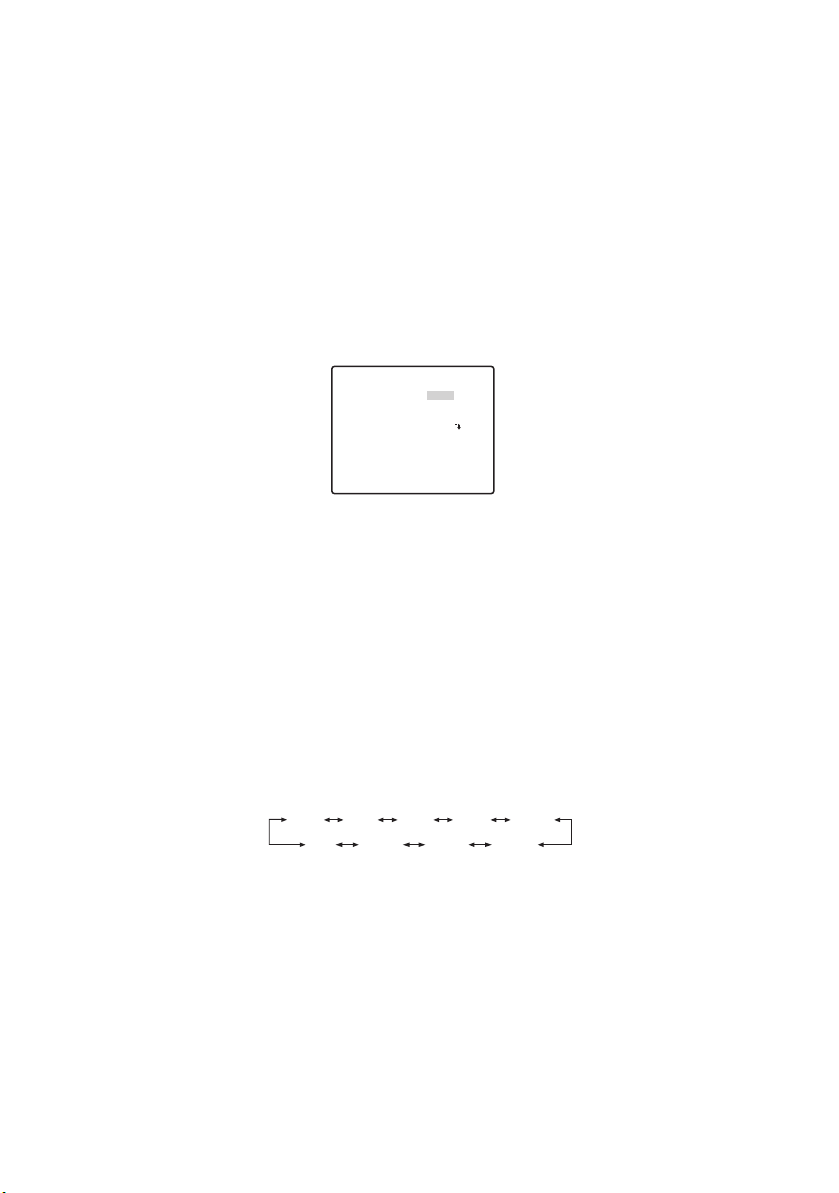
To determine the display position of the CAMERA ID
1. Move the cursor to POSI, and press the SET button.
The display in the figure appears and the CAMERA ID is highlighted.
2. Move the CAMERA ID to the desired position.
3. Press the SET button to fix the position of the CAMERA ID.
WV-CZ352
2 Light Control Setting (ALC/MANUAL)
1. Move the cursor to ALC/MANUAL and select ALC or MANUAL. When you select ALC,
backlight compensation ON or OFF can be set.
Note: The backlight compensation submenu associated with this menu is described
separately and should be set up after installing the camera at the site and observing the actual site picture.
2. When MANUAL is selected, quit the setup menu. Press the OPEN or CLOSE button on
the controller for iris adjustment.
Note: The camera menu cannot be used for iris control.
(1) ALC Mode with BLC ON
** ALC CONT **
BACK LIGHT COMP
BLC
MASK SET
LEVEL
RET TOP END
1. Press the SET button after selecting ALC. The ALC CONT menu appears.
** ALC CONT **
BACK LIGHT COMP
BLC
LEVEL
RET TOP END
2. Move the cursor to the BLC parameter and select ON.
3. If you want to adjust the video output level, adjust the “I” cursor for LEVEL.
OFF
••••|••••
- +
ON
••••|••••
- +
16
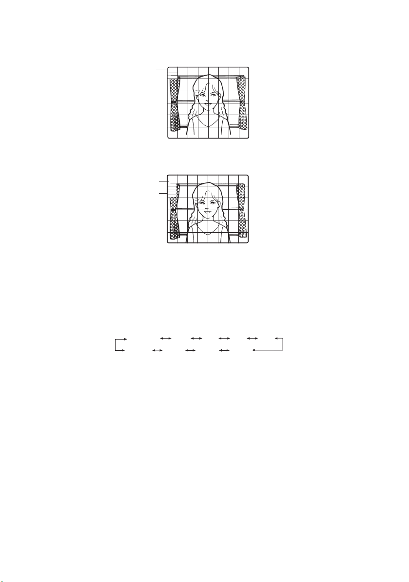
(2) ALC Mode with BLC OFF
1. Move the cursor to BLC and select OFF. (When you select MANUAL, BLC is not available.) MASK SET appears on the menu.
Blinking
2. To mask an area where backlight is bright, move the cursor to the area and press the
SET button. The mask turns white. Repeat this procedure to mask the desired areas.
Turns to white
Blinking
3. To cancel a masked area, move the cursor to the area, and press the SET button. To
delete all the masking area, press the RIGHT and LEFT buttons at the same time for
more than 2 seconds.
4. After masking is completed, press the SET button more than 2 seconds. 48 mask areas
on the monitor screen disappear and the ALC CONT menu appears.
3 Shutter Speed Setting (SHUTTER)
OFF (1/50) 1/120AUTO
1/10 000 1/4 000 1/2 000 1/1 000
●
In the AUTO mode, an object is clearly imaged under highlighted conditions by using
the combination technology of iris and shutter functions.
Note: When the selected shutter speed caused flicker on condition that fluorescent
lamps stay on, change this setting to “OFF”.
1/250 1/500
4 Gain Control Setting (AGC)
Select ON (LOW), ON (MID), ON (HIGH) or OFF.
Notes:
●
Even if AGC is set to ON and if the noise reduction function is enabled, after images
may be produced by shooting a moving object.
●
For more information, refer to Digital Noise Reduction on page 20.
17
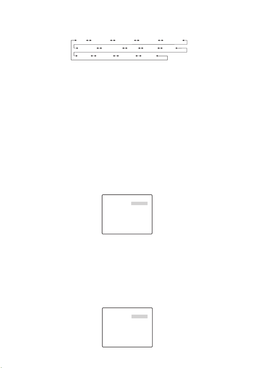
5 Electronic Sensitivity Enhancement (SENS UP)
The electronic sensitivity enhancement mode changes as follows:
OFF
X2 AUTO
X16 AUTO X32 AUTO X2 FIX
X6 FIX X10 FIX X16 FIX X32 FIX
●
While the SENS UP function is selected, noise or spots may appear in the picture when
X4 AUTO X6 AUTO X10 AUTO
X4 FIXOFF
the sensitivity of the camera is increased. This is a normal phenomenon.
6 Synchronization Setting (SYNC)
The priorities of SYNC modes are assigned as follows:
1. Multiplexed vertical drive (VD2)
2. Internal sync (INT)
Note: Whenever the vertical drive pulse (VD2) is supplied to the camera, the camera sync
mode is automatically switched to the multiplexed vertical drive pulse (VD2) regardless of the selected sync mode.
7 White Balance Setting (WHITE BAL)
1. Auto-Tracing White Balance Mode (ATW1/ ATW2)
The range of colour temperature is ATW1 2 600 K-6 000 K
ATW2 2 000 K-6 000 K
* ATW2 is suited to setting when a sodium lamp is used.
(1) The white balance of the camera is automatically adjusted at ATW1 and ATW2.
** ATW1 **
R
B
••••|••••
- +
••••|••••
- +
RET TOP END
(2) For fine adjustment of ATW1/ATW2, press the SET button. The ATW1/ATW2 fine
adjustment menu appears on the monitor screen.
2. Automatic White Balance Control Mode (AWC)
(1) Select AWC n PUSH SET.
(2) Press the SET button to start the white balance setup. PUSH SET is highlighted to
indicate that white balance is being set.
(3) PUSH SET returns to normal when balance setting is completed.
(4) For fine adjustment of the AWC, move the cursor to AWC and press the SET button.
The AWC fine adjustment menu appears on the monitor screen.
** AWC **
R
B
RET TOP END
••••|••••
- +
••••|••••
- +
18

8 Motion Detector Setting (MOTION DET)
1. Select ON or OFF.
2. If ON is selected, press the SET button. The MOTION DETECT menu appears.
You can mask the areas in this menu.
3. Move the cursor to MASK SET and press the SET button. 48 mask areas appear
on the monitor screen.
Refer to Light Control Setting on page 16 for masking operations.
4. After masking areas, press the SET button more than 2 seconds. The MOTION
DETECT menu appears on the monitor screen.
5. Move the cursor to ALARM and select ON or OFF.
ON: The alarm signal is supplied while the display mode is activated.
OFF: The alarm signal is not supplied while the display mode is activated.
6. Move the cursor to DISPLAY MODE.
Press the SET button to see the present setting. The areas that detect the motions blink.
7. Move the cursor to LEVEL.
Obtain the optimum detection level.
** MOTION DET **
LEVEL
DWELL TIME 2S
DISPLAY MODE
ALARM OFF
MASK SET
RET TOP END
8. Dwell Time
Move the cursor to DWELL TIME, and select a time. When the time specified here
elapses after motion detection, the camera will notify the connected device of the alarm
activation.
Selectable times (seconds): 2 s, 5 s, 10 s, 30 s.
••••|••••
- +
Important Notices:
● Motion detection should meet the following conditions.
1) The picture size on the screen should be larger than 1/48 of the actual picture size.
2) The contrast ratio between the object and the background picture should be more
than 5% at the maximum detection level.
3) The time that takes the object to move from one end of the screen to the other
should be more than 0.1 second.
● Also under the following conditions, mask or adjust the detection level to prevent mal-
function.
1) When leaves, curtains, etc. are swayed by the wind.
2) When a picture has a high noise content due to low light conditions.
3) When the object is illuminated by lighting equipment that constantly turns on and
off.
19

● Alarm signal will take approx. 0.2 seconds to reach the alarm terminal of the VTR
after the camera detects the object.
Because the alarm signal is multiplexed on the video signal, it may be mistakenly
interpreted by other video equipment as a time code signal. Therefore, when this
camera is not used in a Panasonic Intelligent CCTV System, select OFF to prevent
the above from occurring.
9 Digital Noise Reduction Setting (DNR)
DNR may be used to improve quality under low light conditions.
There are 4 levels of DNR, which may be selected depending on local site conditions.
LOW1: DNR level is low. The after-image remains.
LOW2: DNR level is low. The after-image is reduced.
HIGH1: DNR level is high. The after-image remains.
HIGH2: DNR level is high. The after-image is reduced.
0 Resolution Setting (RESLOUTION)
Move the cursor to RESOLUTION and select NORMAL or HIGH.
- Black and White Mode Setting (BW MODE)
You can set up the BW mode on this menu.
BW Setting
1. Move the cursor to BW and select EXT, AUTO, ON or OFF.
** BW MODE **
BW OFF
PIX SENS UP OFF
BURST(BW) OFF
RET TOP END
EXT: Changes between the colour and B/W mode according to the D/N IN terminal.
AUTO: The camera selects the black and white mode if the picture is dark, or the colour
mode if the picture is bright enough.
ON: The black and white mode is selected.
OFF: The colour mode is selected.
Note: At the time of EXT setup, the controller cannot be used for ON/OFF control.
2. When AUTO is selected, it becomes possible to set up the LEVEL DURATION
TIME.
3. Select HIGH or LOW for the threshold level at which the camera automatically
switches to BW or colour mode.
The illuminance shown below is based on the assumption that the camera is used in an
area lit by halogen lamps, and that AGC on the menu is set to MID.
20

HIGH: approximately 6 lx
LOW: approximately 2.5 lx
Note: When near-infrared lamps are used, the image may be displayed out of focus
and mode switching may not perform automatically.
4. Move the “I” cursor to set DURATION TIME.
The camera determines whether to switch the mode when the time set for holding a picture motionless on the screen has elapsed.
Available duration times: (S) 10 s n 30 s n 60 s n 300 s (L)
PIX SENS UP Setting
Move the cursor to PIX SENS UP and move the cursor to select OFF or X2 AUTO.
X2 AUTO: Sensitivity will be automatically doubled at the maximum in the black and
white mode.
OFF: Sensitivity will not be enhanced.
Notes:
● “X2 AUTO” is not available when AGC is set to OFF. “X2 AUTO” is automatically set
to OFF.
● When the picture becomes stable, the luminance may change for a moment.
BURST (BW) Setting
Move the cursor to select ON or OFF.
ON: The burst signal is supplied along with the black and white composite video.
OFF: The burst signal is not output.
Note: It is recommended to select ON usually.
= Privacy Zone Setting (PRIVACY ZONE)
Up to 4 unwanted zones can be masked on the monitor screen.
** ZONE NUMBER 1 /4 **
RET TOP END
When the cursor is positioned on a numeral, the setup zone number is selected with the
RIGHT, LEFT or SET button is pressed, the privacy zone mask setup screen is displayed.
** ZONE NUMBER 1 /4 **
ZOOM PUSH SET
POSITION PUSH SET
SCALE PUSH SET
SET DEL
RET TOP END
21

Zoom/Focus
Press the SET and then UP, DOWN, RIGHT or LEFT button to adjust the Zoom and Focus
positions.
Position
Press the SET and then UP, DOWN, RIGHT or LEFT button to set up the mask position
of the privacy zone.
Scale
Press the SET and then UP, DOWN, RIGHT or LEFT button to set up the mask size of the
privacy zone. If there is the cursor in SET, press the SET button to reflect the contents of
setup. If there is the cursor in DEL, press the SET button to delete the setup mask.
Note: If UPSIDE DOWN and MIRROR have been set up after the completion of privacy
zone setup, there may be some displacement of the mask position.
~ Auto Focus Setting (AF MODE)
MANUAL: In this mode, the AF mode activates when the SET button is pressed.
STOP AF: If STOP AF is selected following MANUAL, the AF mode activates during or
after lens operation.
AUTO: If AUTO is selected following STOP AF, the AF mode activates when the illumi-
nance is changed.
Notes:
● Long use in AUTO mode may shorten the service life of the lens drive.
● When the electronic sensitivity enhancement (SENS UP) is activated except in the x2
FIX or x2 AUTO mode, this function is automatically set to MANUAL.
● The auto focus lens may not function properly in the STOP AF and AUTO mode under
the following conditions.
1. Dirt or water on window glass.
2. Low lighting or illumination.
3. Bright objects or high intensity objects.
4. Single colour object such as a white wall or fine felt
5. No centre objects and sloping objects
! Zoom Limit Setting (ZOOM LIMIT)
A limitation is provided to prohibit the ZOOM operation in the direction of TELE, exceeding
the preset value. Optical is available up to X22, and electronic zoom becomes available for
higher levels.
@ Upside-Down Setting (UPSIDE-DOWN)
The video image is reversed upside down during ON setting.
# Mirror Setting (MIRROR)
The video image is reversed to the right and left during ON setting.
22
■ Preset Position Setting
** PRESET POSITION **
PRESET 1
MAP
HOME POSITION OFF
SELF RETURN OFF
IMAGE HOLD OFF
RET TOP END
1 Preset Menu Display
1. Displaying the preset menu directly
(1) Move the cursor to PRESET 1 and select the position number.
(2) Press the SET button. The preset setting menu appears on the monitor screen.
2. Displaying the preset menu from the PRESET NUMBER SET menu
(1) Move the cursor to MAP and press the SET button.
The PRESET NUMBER SET menu appears on the monitor screen.
** PRESET NUMBER SET **
2
1*
5
9
13
17
21
25
29
ID:DOOR
33-64 RET
** PRESET NUMBER SET **
33
37
41
45
49
53
57
61
ID:
1-32 RET TOP END
(2) Move the cursor to the position number to be set and press the SET button.
The preset setting menu appears on the monitor screen. To display any position
number between 33 and 64, move the cursor to “33-64” in the lower left of the
screen and press the SET button.
Notes:
● The * mark indicates that the position number has been preset.
● The character H refers to the home position.
●
The second line from the bottom shows the preset ID corresponding to the selected
number. “DOOR” next to “ID” in the example shown right is for preset position number 1.
34
38
42
46
50
54
58
62
6
10
14
18
22
26
30
3
7
11
15
19
23
27
31
TOP END
35
39
43
47
51
55
59
63
4
8
12
16
20
24
28
32
36
40
44
48
52
56
60
64
q
w
e
r
PRESET NO. 1
POSITION SET
PRESET ID ON
ALC/MANUAL ALC
AF MODE MANUAL
SCENE FILE OFF
RET TOP END DEL
A
B
C
D
E
F
23

APosition Setting (POSITION SET)
1. Move the cursor to POSITION SET on the preset setting menu and press the
SET button.
The POSITION setting menu appears.
(1) Move the cursor to PUSH SET for ZOOM/FOCUS and press the SET button.
** POSITION 1 **
ZOOM/FOCUS PUSH SET
RET TOP END
(2) Select a zoom position and a focus position, and then press the SET button.
The positions are set and the screen returns to the position setting menu.
Note: If you move the cursor to the position number and press the LEFT or RIGHT
button, the position number can be selected.
The selected preset position number can also be set after pressing the SET button.
BPreset Identification Setting (PRESET ID)
1. Move the cursor to PRESET ID on the preset setting menu and select ON or
OFF.
ON: Preset ID appears on the monitor screen.
OFF: Preset ID does not appear.
2. Press the SET button to display the preset ID setting menu.
To Enter a New Preset ID
For registration, refer to the items of CAMERA ID on Page 15.
24
To Copy a Preset ID from Another Position
(1) Move the cursor to COPY and press the SET button. The preset ID in the preced-
ing position is immediately shown. Each consecutive pressing of the SET button
displays the ID preceding the one currently displayed.
(2) Display the most prospective ID.
PRESET NO. 1*
0123456789
ABCDEFGHIJKLM
NOPQRSTUVWXYZ
().,'":;&#!?=
+-*/%$ДЬЦЖСЕ
SPACE
COPY POSI RET RESET
DOOR............
(3) Follow the step “To Change an Entered Preset ID” if necessary.
To Enter the Next ID without Returning to the Preset Setting Menu
(1) In the preset ID setting menu, move the cursor to the top line and select a desired
position number.
(2) Enter, copy, change or delete the ID as described above.
CLight Control Setting (ALC/MANUAL)
Refer to Light Control Setting on page 16.
DAuto Focus Setting (AF MODE)
Refer to Auto Focus Setting on page 22.
EScene File Setting (SCENE FILE)
1. To set a scene file number
Move the cursor to SCENE FILE and select a scene file number (1 to 10, or
OFF). No scene file is selected at OFF.
2. To set scene file details
Move the cursor to a scene file number and press the SET button. The setting menu
appears.
** SCENE FILE 1 **
SHUTTER
AGC
SENS UP
WHITE BAL
MOTION DET
RET TOP END
AUTO
ON(MID)
OFF
ATW1
OFF
FDeleting Preset Positions
Move the cursor to DEL and press the SET button.
2 Home Position Setting (HOME POSITION)
1. To set a position number for the home position Move the cursor to HOME POSITION and select a desired position number.
2. Select OFF if you are not using the home position function.
3 Self Return Setting (SELF RETURN)
This menu is used to set up the time needed to return to the home position automatically.
Move the cursor to SELF RETURN, select a return time from among the following
and press the SET button to confirm your selection.
2MIN 3MIN 5MIN 10MIN
1MIN
OFF
60MIN
30MIN 20MIN
MIN stands for minute(s).
4 Image Hold (IMAGE HOLD)
The camera picture remains as a still image on the monitor screen until the camera reaches the preset position. This function is useful for surveillance via local area network.
Move the cursor to IMAGE HOLD and select ON or OFF.
25

■ Special Setting
** SPECIAL SETUP **
CHROMA GAIN ••••|••••
AP GAIN ••••|••••
PEDESTAL ••••|••••
- +
PIX OFF
ZOOM INVERSE OFF
FOCUS INVERSE OFF
REFRESH PUSH SET
CAMERA RESET PUSH SET
RET TOP END
1 Chroma Level (CHROMA GAIN)
2 Aperture Level (AP GAIN)
3 Pedestal Level (PEDESTAL)
Move the cursor to CHROMA GAIN, AP GAIN and PEDESTAL and move the “I” cursor to
your desired position.
4 PIX OFF Setting (PIX OFF)
In this setting, you can assign a blemish position and compensate the blemish.
Move the cursor to PIX OFF and press the SET button. The PIX OFF menu appears.
1.
** PIX OFF **
1* 2* 3* 4*
5* 6* 7* 8
000 000
RET TOP END
2. Select a number and press the SET button. The blemish compensation position
setting screen appears.
Move the “+” cursor to the place on the blemish position. After moving the “+” cursor to
a position where the blemish looks inconspicuous, press the SET button. Consequently,
the blemish compensation position is set up and the PIX OFF menu is restored.
After a blemish compensation position is set up, “*” is attached at the right of the number.
q
w
e
r
t
y
u
i
3. If you would like to delete a blemish compensation position, move the cursor to
the applicable number and press the SET button.
The blemish compensation position setting screen appears.
+
The blemish compensation position is deleted and “*” is also deleted from the right
of the number by pressing the RIGHT and LEFT buttons for more than 2 seconds.
26

5 ZOOM INVERSE
The TELE/WIDE operation from the lens control terminal or the UP and DOWN buttons is
reversed during ON setting.
6 FOCUS INVERSE
The FAR/NEAR operation from the lens control terminal or the UP and DOWN buttons is
reversed during ON setting.
7 REFRESH
Move the cursor to REFRESH and press the RIGHT and LEFT buttons at the same time
for more than 2 seconds. Then, the Refresh operation is started.
8 CAMERA RESETTING (CAMERA RESET)
Move the cursor to CAMERA RESET and press the RIGHT, LEFT, and SET buttons at the
same time for more than 2 seconds.
The camera is reset to the factory default settings.
Notes:
● Any of the following cannot be reset to the factory defaults: Preset Position Setting
(POSITION SET, PRESET ID, ALC/MANUAL, AF MODE, SCENE FILE),
Communication Setting, Password Lock Setting, PIX OFF setting.
● In case of performing this operation on the condition that the cursor is positioned on
other than CAMERA RESET, you cannot perform the operations on the menu thereafter.
In that event, set the camera menu to ON again with the controller referring to page 23.
■ Communication Setting
**COMMUNICATION SETUP**
COMMUNICATION RS485
RET TOP END
Move to the cursor to “COMMUNICTION” and select RS485 or COAX or COAX (RCV).
COAX: Communication is carried out in the coaxial multiplex system.
COAX (RCV):
RS485: Communication is maintained through the RS485 terminal. When RS485 is set up
●
Changing the Camera Communication Parameters for RS485.
If our receiver (WV-RC100, WV-RC150, WV-RC170) is used, select COAX (RCV).
and the SET button is pressed, the RS485 setup screen is displayed.
** RS485 SET UP **
UNIT NUMBER
SUB ADDRESS
BAUD RATE
DATA BIT
PARITY CHECK
STOP BIT
XON/XOFF
WAIT TIME
ALARM DATA
DELAY TIME
RET TOP END
1
––––
19200
8
NONE
1
NOT USE
OFF
AUTO2
OFF
27

Move the cursor to the item and select the parameter.
Unit Number
In an RS485 chain each unit must have a unique number.
Sub Address
Do not set.
Baud Rate
Specifies the transmission speed (2 400, 4 800, 9 600, 19 200 bit per second) for the RS485
communication.
Data Bit
Specifies the number of data bits (7 or 8 bits) for the RS485 communication.
Parity Check
Specifies the parity check mode (NONE, ODD, EVEN).
Stop Bit
Specifies the number of stop bits (1 or 2 bits).
X ON/X OFF
Specifies whether to apply flow control or not (USE or NOT USE).
Wait Time
Specifies the time to wait until retrying after confirming that no data is received from the controller. (OFF: no retry, 100, 200, 400, 1 000 ms).
Alarm Data
Specifies the alarm transmission mode.
POLLING: Transmits the alarm data in response to requests from the controller.
AUTO 1: Transmits the alarm data each time an alarm signal is received by the camera.
AUTO 2 (Default): Transmits alarm data at intervals of 5 seconds.
Delay Time
Specifies the time to transmit the acknowledge request when communicating on a
2-line connection.
[----, 100 ms] Factory default setting: ---- (no set).
This menu appears only when a 2-line communication is used. Make sure to be 100
ms when connecting the camera with the Video Multiplexer or the Matrix Switcher in a 2-line
communication system.
The settings become effective with the closing of SETUP menu.
Note: Set the same parameters for the cameras, controllers and personal computers in an
RS485 chain.
■ Password Lock Setting
Caution: For security, do not operate your VTR for recording while the password menus are
displayed on the monitor.
A 3-digit number is used for a password to limit access to all settings.
28

1. Move the cursor to PASSWORD LOCK.
** PASSWORD? **
0 1 2 3 4 5 6 7 8 9
. . .
OK RESET
NEW PASSWORD
RET TOP END
↑
Note: ON or OFF can be selected only after going through the password verification.
OFF: You can change all settings.
ON: You cannot change all settings.
2. Press the SET button.
Password Verification
3. The password verification menu appears.
3-1 Select a numeral for the first digit with the cursor, and press the SET button. Though
the entered password is not displayed, the up-arrow moves one character to the right.
3-2 Repeat the above step for the 2nd and 3rd digits. Default: 123
3-3 The cursor moves to OK after all the three digits have been entered.
Unless you want to change the password, press the SET button.
If the correct password is entered, the screen returns to SETUP menu. ON and OFF
settings are the same as made on the SETUP menu is as set in step 1.
If a wrong password is entered, the screen returns to the verification menu. Repeat
steps 3-1 to 3-3 to verify the password.
3-4 To cancel an incomplete password, move the cursor to RESET, and press the SET
button. The screen returns to the verification menu.
New Password
4. To change the password in step 3-3 above, move the cursor from OK to NEW PASSWORD, then press the SET button. NEW PASSWORD menu appears.
** NEW PASSWORD? **
0 1 2 3 4 5 6 7 8 9
. . .
. . .
OK RESET
RET TOP END
↑
Note: The NEW PASSWORD menu is accessible only after the verification has been com-
pleted. The up-arrow mark appears indicating the first digit on the first line.
4-1 Enter a new three-digit password in the same way as in steps 3-1 to 3-2.
4-2 The cursor moves to OK after all the three digits have been entered. Press the SET
button to move the cursor to the first digit on the second line.
4-3 Enter the same password as the one you have entered on the first line.
4-4 The cursor moves to OK. Press the SET button. If the new password is successfully
entered, the screen returns to SETUP menu.
4-5 Retry steps 4-1 to 4-4. If the first entry for the password is different from the second
one, the screen returns to the NEW PASSWORD menu.
29

SPECIFICATIONS
1/4-type {1/4"} interline transfer CCDPick-up Device
752(H) x 582(V)Effective Pixels
3.65 mm (H) x 2.71 mm (V), 1/4-type {1/4"}Scanning Area
internal / multiplexed vertical drive (VD2)synchronization
Horizontal Scanning Frequency
Ver tical Scanning Frequency
Horizontal Resolution more than 510 TV lines at centre (C/L, HIGH),
Minimum Illumination in
Day/Night mode
Angular Field of
view
Ambient Operating Temperature
Weight
Day/Night IN
Alarm OUT
15.625 kHz
50.00 Hz
1.0 V [P-P] PAL composite/75 ΩVideo Output
more than 480 TV lines at centre (C/L, NORMAL),
570 TV lines at centre (Day/Night mode)
more than 400 TV lines at centreVer tical Resolution
50 dB (AGC OFF, weight on)Signal-to-Noise Ratio
1 lx {0.1 foot-candle} C/L at SENS UP OFF (AGC HIGH)Minimum Illumination
0.06 lx {0.006 foot-candle} with PIX SENS UP
OFF,B/W, SENS UP OFF (AGC HIGH)
0.03 lx {0.003 foot-candle} with PIX SENS UP x2 AUTO,
B/W, SENS UP OFF (AGC HIGH)
approx. 4.5 s (TELE/WIDE) in manual modeZoom Speed
approx. 5 s (FAR/NEAR) in manual modeFocus Speed
automatic (open/close is possible)/manualIris
1:1.6 (WIDE) - 3.0 (TELE)Maximum Aperture Ratio
3.79 - 83.4 mmFocal Length
2.6˚- 52.3˚
H
2.0˚ - 39.9˚
V
1/50 (OFF), AUTO 1/120, 1/250, 1/500, 1/1 000, 1/2 000, 1/4 000, 1/10 000 sElectronic Shutter
ON (LOW)/ON (MID)/ON (HIGH)/OFFAGC
MAX 32 times, AUTO/FIX Sens UpSens UP
selectable ON/OFF (SETUP MENU)BLC
x 22 +digital zoom x10Zoom Ratio
F1.6 - 22, CLOSEIris Range
12 V DCPower Source
490 mAPower Consumption
-10 ˚C - +50 ˚C {14 ˚F - 122 ˚F}
78 mm(H) x 62 mm(W) x 119 mm(L) {3.07 inch(H) x 2.44 inch(W) x 4.69 inch(L)}Dimensions
0.34 kg {0.75 lbs}
MANUAL/STOP AF/AUTOAuto Focus
preset ID, camera ID, up to 16 charactersCamera ID
ON/OFFMotion Detector
Input pulled up to 5.0 V DC OFF
(open or 4 V DC - 5 V DC) /ON (0 V 0.2 mA)
Output open collector - output max. 16 V DC, 100 mA
OFF (OPEN)/ON (0 V)
AUTO/ON/OFF/EXTB/W Mode
ON/OFF, up to 4 zonesPrivacy Zone
ON/OFFImage Hold
STANDARD ACCESSORIES
Operating instructions (this document) . . . . . . . . . . . . . . . . . . . . . . . . . . . . . . . . . . . . . . . . .1 pc
30
 Loading...