

Page 1
Before attempting to connect or operate this product,
please read these instructions carefully and save this manual for future use.
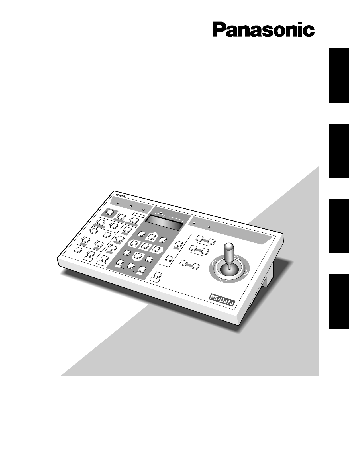
Model No. WV-CU360
System Controller
Operating Instructions
System Controller WV-CU
360
O
PERATE
LO
GIN
A
LARM
M
ONITOR
UNIT
CAM
ERA
BUSY
PROHIBITED
S
H
IFT
F
U
N
C
TIO
N
C
A
M
F
U
N
C
TIO
N
P
R
O
G
R
A
M
A
LM
R
E
SE
T
V
TR
C
AM
MULTI SCREEN SELECT
STILL
–
S
E
Q
P
A
U
S
E
S
E
Q
U
E
N
C
E
S
L
O
W
P
A
T
R
O
L
L
E
A
R
N
P
R
O
G
R
A
M
P
R
E
S
E
T
P
A
T
R
O
L
S
T
O
P
E
S
C
S
E
T
L
O
G
O
U
T
M
O
N
C
A
M
P
A
T
R
O
L
P
L
A
Y
+
A
U
X
1
W
IPE
R
H
O
M
E/P
R
E
SE
T
A
U
X
2
D
EF
U
N
IT
B
Z
O
O
M
W
ID
E
TE
LE
D
O
W
N
L
R
U
P
E
L
-Z
O
O
M
ALM
RECALL
ALM
S
U
SP
EN
D
A
U
TO
F
O
C
U
S
FA
R
N
E
AR
U
N
IT A
U
N
IT
B
/W
SETUP
CAM SETUP
CLOSE
IRIS
OPEN
IRIS RESET
AUTO FOCUS
8
9
7
0
4
5
6
2
3
1
ENGLISH
DEUTSCH
FRANÇAIS
ESPAÑOL
Page 2
2
ENGLISH VERSION
The serial number of this product may be found on the
bottom of the unit.
You should note the serial number of this unit in the
space provided and retain this book as a permanent
record of your purchase to aid identification in the event
of theft.
Model No. WV-CU360
Serial No.
The lightning flash with arrowhead symbol, within an equilateral triangle, is
interned to alert the user to the presence
of uninsulated "dangerous voltage" within the product's enclosure that may be of
sufficient magnitude to constitute a risk
of electric shock to persons.
The exclamation point within an equilateral triangle is intended to alert the user
to the presence of important operating
and maintenance (servicing) instructions
in the literature accompanying the appliance.
WARNING:
TO PREVENT FIRE OR ELECTRIC SHOCK HAZARD, DO NOT EXPOSE THIS APPLIANCE TO RAIN OR MOIS
TURE.
CAUTION:
TO REDUCE THE RISK OF ELECTRIC SHOCK,
DO NOT REMOVE COVER (OR BACK), NO USER
SERVICEABLE PARTS INSIDE.
REFER SERVICING TO QUALIFIED SERVICE
PERSONNEL.
CAUTION
RISK OF ELECTRIC SHOCK
DO NOT OPEN
CAUTION:
Before attempting to connect or operate this product, please read the label on the bottom.
Wij verklaren als enige aansprakelijke, dat het product waarop deze
verklaring betrekking heeft, voldoet aan de volgende normen of
andere normatieve documenten, overeenkomstig de bepalingen
van Richtlijnen 73/23/EEC en 89/336/EEC.
Vi erklærer os eneansvarlige for, at dette produkt, som denne
deklaration omhandler, er i overensstemmelse med standarder eller
andre normative dokumenter i følge bestemmelserne i direktivene
73/23/EEC og 89/336/EEC.
Vi deklarerar härmed värt fulla ansvar för att den produkt till vilken
denna deklaration hänvisar är i överensstämmelse med standarddokument, eller andra normativa dokument som framställs i EECdirektiv nr. 73/23 och 89/336.
Ilmoitamme yksinomaisella vastuullamme, että tuote, jota tämä
ilmoitus koskee, noudattaa seuraavia standardeja tai muita ohjeellisia asiakirjoja, jotka noudattavat direktiivien 73/23/EEC ja
89/336/EE. säädöksiä.
Vi erklærer oss alene ansvarlige for at produktet som denne
erklæringen gjelder for, er i overensstemmelse med følgende
normer eller andre normgivende dokumenter som følger bestemmelsene i direktivene 73/23/EEC og 89/336/EEC.
We declare under our sole responsibility that the product to which
this declaration relates is in conformity with the standards or other
normative documents following the provisions of Directives
EEC/73/23 and EEC/89/336.
Noi dichiariamo sotto nostra esclusiva responsabilità che il prodotto
a cui si riferisce la presente dichiarazione risulta conforme ai
seguenti standard o altri documenti normativi conformi alle disposizioni delle direttive CEE/73/23 e CEE/89/336.
Page 3

3
CONTENTS
PREFACE ...................................................................................................................................................................................... 4
FEATURES .................................................................................................................................................................................... 4
PRECAUTIONS ............................................................................................................................................................................. 4
MAJOR OPERATING CONTROLS AND THEIR FUNCTIONS ...................................................................................................... 5
■ Front View .............................................................................................................................................................................. 5
■ Rear View ............................................................................................................................................................................... 8
INSTALLATIONS .......................................................................................................................................................................... 9
■ Dip Switch Setting ................................................................................................................................................................. 9
■ Controller Number Setting ..................................................................................................................................................... 9
SETUP ........................................................................................................................................................................................ 10
■ Setup Procedures ................................................................................................................................................................ 10
KEY FUNCTIONS OF SETUP MENU ......................................................................................................................................... 10
SETUP MENU ............................................................................................................................................................................. 11
■ Setup Menu ........................................................................................................................................................................... 11
■ Displaying the Setup Menu ................................................................................................................................................... 11
SYSTEM CONNECTIONS ............................................................................................................................................................. 14
■ Connections to the WJ-MP204 Data Multiplex Units (Panasonic Security Data Mode) ......................................................... 14
■ Connections with the AC Adapter ......................................................................................................................................... 14
■ Connections in Panasonic Security Data Mode .................................................................................................................... 15
OPERATING PROCEDURES ........................................................................................................................................................ 16
BASIC OPERATING FLOW ........................................................................................................................................................ 16
LOG IN/LOG OUT ................................................................................................................................................................... 17
■ LOG IN ................................................................................................................................................................................... 17
■ LOG OUT ............................................................................................................................................................................... 17
SYSTEM SELECTION ............................................................................................................................................................... 18
■ System Unit Selection ............................................................................................................................................................ 18
■ Monitor Selection ................................................................................................................................................................... 19
■ Camera Selection .................................................................................................................................................................. 19
CONTROLLING SYSTEM FUNCTIONS ..................................................................................................................................... 20
CAMERA CONTROL FUNCTIONS ............................................................................................................................................ 22
■ Pan/Tilt Control ...................................................................................................................................................................... 22
■ Lens Control .......................................................................................................................................................................... 22
■ Operation of Combination Camera ........................................................................................................................................ 22
■ Camera Housing Control ....................................................................................................................................................... 26
■ External Device Control ......................................................................................................................................................... 26
ALARM CONTROL FUNCTIONS ............................................................................................................................................... 27
■ Alarm Operation .................................................................................................................................................................... 27
■ Alarm Reset ........................................................................................................................................................................... 27
■ Alarm Suspend ...................................................................................................................................................................... 27
■ Alarm Recall .......................................................................................................................................................................... 27
ALL RESET ................................................................................................................................................................................... 27
SYSTEM UNIT AND CAMERA SETUP .......................................................................................................................................... 28
SPECIFICATIONS ......................................................................................................................................................................... 31
STANDARD ACCESSORIES ......................................................................................................................................................... 31
ENGLISH
Page 4

4
PRECAUTIONS
• Refer all work related to the installation of this
product to qualified service personnel or system
installers.
• Do not attempt to disassemble the appliance.
To prevent electric shock, do not remove screws or
covers.
There are no user-serviceable parts inside. Contact
qualified service personnel for maintenance.
• Handle the appliance with care.
Do not strike or shake, as this may damage the appliance.
• Do not expose the appliance to water or moisture,
nor try to operate it in wet areas.
Do take immediate action if the appliance becomes
wet. Turn the power Off and refer servicing to qualified
service personnel. Moisture may damage the appliance and also cause electric shock.
• Do not use strong or abrasive detergents when
cleaning the appliance body.
Use a dry cloth to clean the appliance when it is dirty.
When the dirt is hard to remove, use a mild detergent
and wipe gently.
• Do not operate the appliance beyond its specified
temperature, humidity or power source ratings.
Do not use in the appliance in an extreme environment
where high temperature or high humidity exists.
Use the appliance at temperatures within –10˚C +50˚C (14˚F – 122˚F) and a humidity below 90 %. The
input power source for this appliance is 220 - 240 V AC
50 Hz by use of the AC Adapter supplied.
• Do not use other AC adapters than the supplied AC
adapter.
PREF ACE
The WV-CU360 System Controller is designed to control
multiple system units compatible with Panasonic Security
Data mode such as WJ-MP204 Data Multiplex Unit.
Combined with the WJ-MP204 Data Multiplex Unit, the WVCU360 can also control the operation of the cameras connected to the above devices, including their lenses, electronic zoom, auto focus, and pan/tilt heads.
Up to four WV-CU360s can be used in a system.
The WV-CU360 allows you to set up password protection.
Please also refer to the Operating instructions of the WVCU360 and other peripherals.
The WV-CU360 and other devices compatible with
Panasonic Security Data mode have the logo .
FEATURES
The WV-CU360 offers the following functions:
• Camera channel selection (Up to 199 cameras)
• Alarm (Display/Suspend/Recall/Reset)
• Camera and system unit setup
• Surveillance video switching
Remote control of the cameras using Panasonic Security
Data mode and the WV-CU360 System Controller, including:
• Pan/Tilt: Pan/Tilt/Auto Pan/Auto Sort/Auto
Sequence/Random Pan/Preset Position/Home
Position/Camera Patrol
• Lens functions: Iris/Focus/Auto Focus/Zoom
• Housing: Defroster/Wiper/Auxiliary 1, 2
• Other Camera Controls: Camera Function/Camera
Setup
Remote control of the system unit using Panasonic Security
Data mode and the System Controller WV-CU360, including:
Switching of Live and Playback/Changing of the number of Multiscreen Picture/Still/Electronic Zoom/
Sequence/
Monitor Selection (Up to 99 monitors)
System Unit Selection (Up to 99 system units)
Page 5
5
MAJOR OPERATING CONTROLS AND THEIR FUNCTIONS
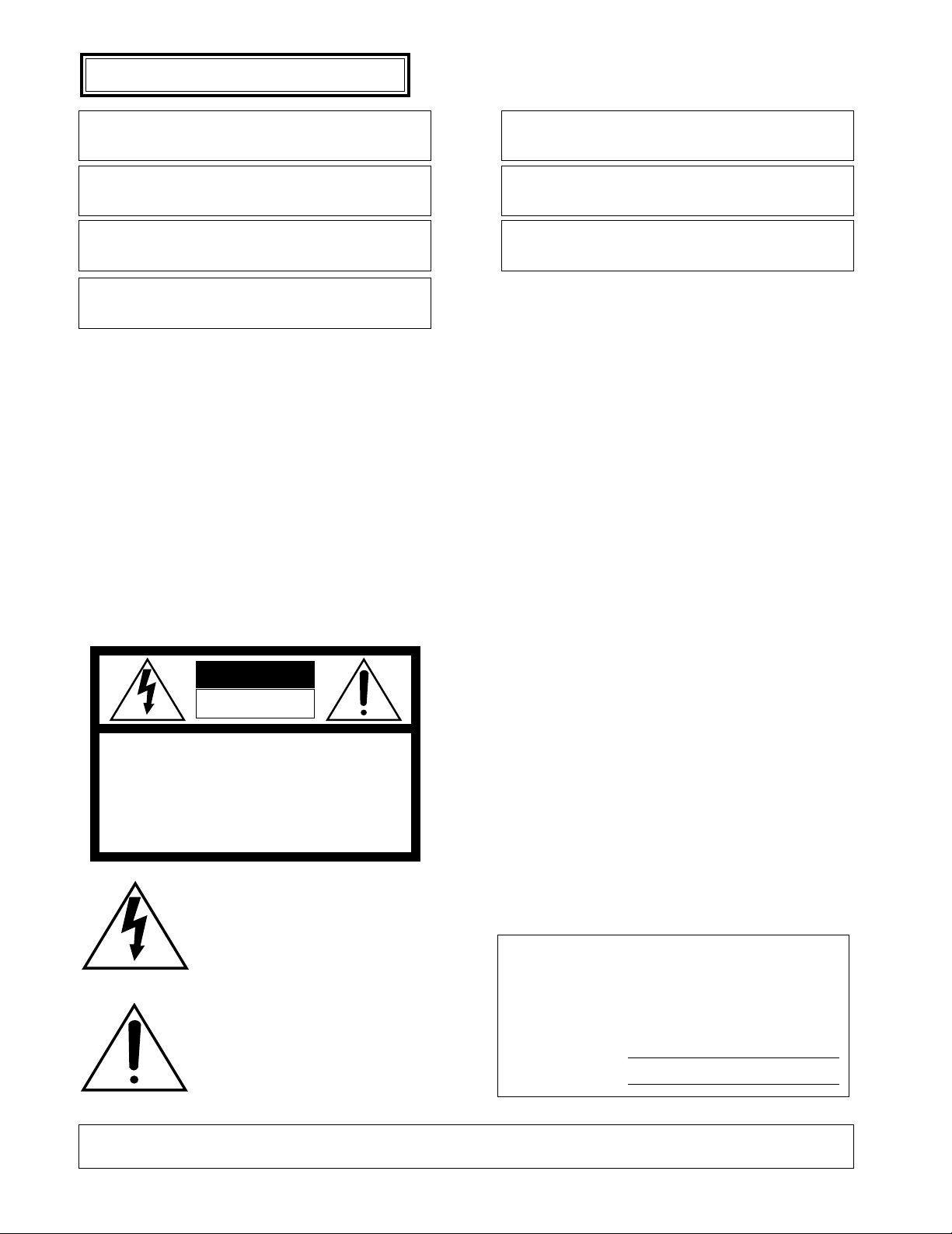
■ Front View
q Operate indicator (OPERATE)
Lights up while the power of the System Controller is
turned on.
w Login indicator (LOGIN)
Lights up when communication has been established
with the WJ-MP204 Data Multiplex Unit.
e Alarm indicator (ALARM)
Lights up when an alarm is activated.
The blink changes to steady light when the alarm is
automatically reset.
To turn the indicator off, press the Alarm Reset button.
r Monitor/Unit indicator ( MONITOR/ UNIT)
The monitor number displays when this indicator lights
up. The unit address displays when this indicator goes
off.
t LED Display
Displays to confirm the number of monitor, units and
camera currently controlled.
It also displays numeric input, error status, etc.
Monitor or Unit number displays after the communication established for the first time.
y Busy indicator (BUSY)
Lights up when you attempt to control a system unit (or
camera) that is already used by a higher priority operator, or when the higher priority operator selects the
camera or system unit equipped with busy indicator
you are currently operating.
Operations from the System Controller are disabled
until this indicator goes off.
u Prohibited indicator (PROHIBITED)
Lights up when you access to a function that is prohibited at operator level.
i Joystick Controller (UP/DOWN/L/R)
This joystick is used to manually operate the Pan/Tilt
Head, or move the cursor in the Setup menu on the
active monitor screen. The joystick can also be moved
in 8 directions.
Keeping the Joystick Controller pushed down in the
desired position will keep the cursor moving continuously in the Setup menu. (See page 10.)
UP: Upward
DOWN: Downward
L: Left
R: Right
OPERATE LOGIN ALARM
CAM SETUP
PROGRAM
PROGRAM
PRESET
UNIT A
IRIS
CLOSE OPEN
NEAR FAR
WIDE TELE
FOCUS
ZOOM
AUTO FOCUS
IRIS RESET
AUTO
SETUP
ALM SUSPEND
FUNCTION
CAM FUNCTION
MULTI SCREEN SELECT
DEF
WIPER
EL-ZOOM
SHIFT
ALM RESET
VTR CAM
STILL
–
+
ALM RECALL
PATROL
LEARN
PATROL
STOP
AUX 1
AUX 2
B/W UNIT
SEQ PAUSE
SLOW
SEQUENCE
PATROL PLAY
HOME/PRESET
UNIT B
MON
CAM
LOGOUT
ESC SET
UP
LR
DOWN
BUSY PROHIBITED
MONITOR
UNIT
CAMERA
System Controller
WV-CU
360
q
we rt yuo i
!1 !0!4!5!6!7
!8
@6
@3
@4
@5
!3
!2
@0
!9
@1
@2
@8
#0
#2
#1
@9
@7
Page 6

6
o Iris buttons (IRIS, CLOSE/OPEN)
These buttons are used to close or open the lens iris of
cameras equipped with the specified lens.
When these buttons are pressed simultaneously, the
lens iris is reset to the factory default settings.
!0 Focus buttons (FOCUS, NEAR/FAR)
These buttons are used to adjust the lens focus of cameras equipped with the specified lens.
When these buttons are pressed simultaneously, the
lens focus is set automatically if the specified camera is
used.
!1 Zoom buttons (ZOOM, WIDE/TELE)
These buttons are used for zooming cameras equipped
with the specified lens.
!2 Unit A/UNIT button (UNIT A/UNIT)
Selects a specific System Unit in a multiple Unit system.
To select a Unit, press this button after entered the unit
number with the Numeric button. Or to confirm a unit
number, press this button after pressing the SHIFT button. The selected unit address appears on the LED display (See page 18 and 28).
The unit that is assigned to number 1 can be selected
by pressing this button.
!3 Unit B button (UNIT B)
Selects a specific System Unit in a multiple Unit system.
To select a Unit, press this button after entered the unit
number with the Numeric button. The selected unit
address appears on the LED display (See page 18 and
28).
The unit that is assigned to the number 1 can be selected by pressing this button.
!4 Home/Preset/Program Preset button
(HOME/PRESET/PROGRAM PRESET)
This button is used to return the direction of a specific
camera to a home position.
In combination with the Numeric buttons, this button is
also used to assign a preset position to a specific camera.
Pressing it while holding down the Program/Camera
Setup/Camera Function button will program preset
position.
!5 Numeric buttons (0-9)
These buttons are used for numeric input, such as camera, monitor, unit numbers, and preset positions.
!6 Camera/Set button (CAM/SET)
CAM: Used for camera selection. To select a camera,
enter the desired Camera number with the Numeric
buttons, and then press this button.
SET: Executes the currently highlighted setting in the
Setup menu.
Pressing this button together with the MON/ESC button
for approximately 2 seconds will log out from the system.
!7 Monitor/Escape button (MON/ESC)
MON: Used for monitor selection and confirmation. To
select a monitor, enter the desired Monitor number
with the Numeric keys, and then press this button.
The selected monitor number appears on the LED
display.
To confirm a monitor number, simply this button.
ESC: This button is used to escape from the currently
highlighted selection and return to the previous
menu of the Setup Menu.
Pressing this button together with the CAM/SET button
for approximately 2 seconds will log out from the system.
!8 Program/Camera Setup/Camera Function button
(PROGRAM/CAM SETUP/CAM FUNCTION)
Pressing this button for 2 seconds or more will open the
camera setup menu. Pressing it in combination with the
Numeric buttons after pressing the Shift button will execute camera functions. The LED next to the button is lit
during the camera setup operation.
This button is used to program camera patrol learning
and preset position functions.
!9 Setup/Function button (SETUP/FUNCTION)
Pressing this button for 2 seconds or more will open the
Setup menu of system unit. Pressing it after pressing
the Shift button will function the system unit in combination with the Numeric buttons.
The LED next to the button is lit during the setup operation.
@0 Shift button (SHIFT)
Pressing this button in combination with buttons to
which special functions have been assigned will activate these functions.
The LED next to the button is lit when the button is
pressed.
The LED next to the button is gone off when the button
is pressed again.
@1 Auto Panning/Black and White button (AUTO/B/W)
Pressing this button will activate the auto panning function of cameras provided with this feature. Pressing it
after pressing the Shift button will display the picture
which changed to a black and white picture on the
monitor.
AUTO PAN ON or Functions that is set in combination camera: Simply press this button, or press
Numeric button 1 followed by this button.
AUTO SORT ON: Press Numeric button 2 followed by
this button.
AUTO SEQ ON: Press Numeric button 3 followed by
this button.
RANDOM PAN ON: Press Numeric button 4 followed
by this button.
Page 7

7
@2 Defroster/Auxiliary 2 button (DEF/AUX 2)
Pressing this button will activate the housing defroster
of cameras provided with this feature. Pressing it after
pressing the Shift button will turn on the AUX2 button
controlling accessories connected to the cameras or
the system.
The LED next to the button is lit while the defroster or
AUX2 mode is selected.
@3 Wiper/Auxiliary 1 button (WIPER/AUX 1)
Pressing this button will activate the housing wiper of
cameras provided with this feature. Pressing it after
pressing the Shift button will turn on the AUX1 button
controlling accessories connected to the cameras or
the system.
The LED next to the button is lit while the wiper or AUX1
mode is selected.
@4 Patrol Play/Patrol Learn button (PATROL PLAY/
PATROL LEARN)
Pressing this button will turn on the camera patrol play
function. Pressing this button while holding down the
Program/Camera setup/Camera function button, will
start to program the camera patrol learning function.
@5 Alarm Suspend button (ALM SUSPEND)
Pressing this button will activate the alarm suspension
mode (alarm input is ignored).
The LED next to the button is lit while alarm suspension
mode is selected.
@6 Alarm Reset/Alarm Recall button (ALM RESET/ALM
RECALL)
Pressing this button while the alarm function is activated will reset the alarm of the system.
Pressing this button after pressing the shift button will
recall the alarm logs (record of alarms activated in the
past).
Select a monitor, and then press this button to display
the alarm logs on the monitor screen. Pressing the button after pressing the shift button again will cancel the
function.
The LED next to the button is lit while Alarm Recall
mode is activated.
@7 Multiscreen Selection button (MULTI SCREEN
SELECT)
This button is used to operate the multiscreen monitor
connected to the MULTISCREEN OUT connector of the
Video Multiplexer.
Note: The above operation in not available unless a
multiscreen monitor is selected.
@8 VTR/Camera Selection button ( VTR/ CAM)
Selects to confirm VTR playback picture for display on
the multiscreen monitor.
The LED next to the button is lit while VTR mode is
selected.
@9 Electronic Zoom/Increment button (EL-ZOOM/+)
Pressing this button will zoom the camera picture or
VTR playback picture displayed on the multiscreen
monitor.
Pressing it after pressing the Shift button moves the
camera sequence one step forward from the step previously paused on the monitor by pressing the SEQ
PAUSE button (This function is available only to system
units with the sequence pause function).
Pressing this button after pressing the Shift button will
replace the currently selected camera with the next
higher camera number (This function is available to
Data Multiplex Unit such as the WJ-MP204).
The LED next to the button is lit while Electronic Zoom
mode is selected.
#0 Still/Decrement button (STILL/–)
Pressing this button will freeze the camera picture or
VTR playback picture displayed on the multiscreen
monitor.
Pressing it after pressing the Shift button moves the
camera sequence one step backward from the step
previously paused on the monitor by pressing the SEQ
PAUSE button (This function is available only to system
units with the sequence pause function).
Pressing it after pressing the Shift button will replace
the currently selected camera with the next lower camera number (This function is available to Data Multiplex
Unit such as the WJ-MP204).
The LED next to the button is lit while Still mode is
selected.
#1 Sequence/Patrol Stop button (SEQUENCE/PATROL
STOP)
Pressing this button will activate Sequence mode. In
this mode, a series of camera pictures is displayed in
succession on the monitor screen for the specified
duration. Pressing it while holding down the Program
/Camera Setup/Camera Function button will stop to program the camera patrol learning function.
The LED next to the button is lit while Sequence mode
is selected.
#2 Sequence Pause/Slow button (SEQ PAUSE/SLOW)
This button is used to bring a running sequence on the
selected monitor to a pause. In this mode, a series of
camera pictures is displayed in pause on the monitor
screen for the specified duration. If this button is
pressed while the joystick controller is moved, pan/tilt
speed will decrease.
Page 8
8
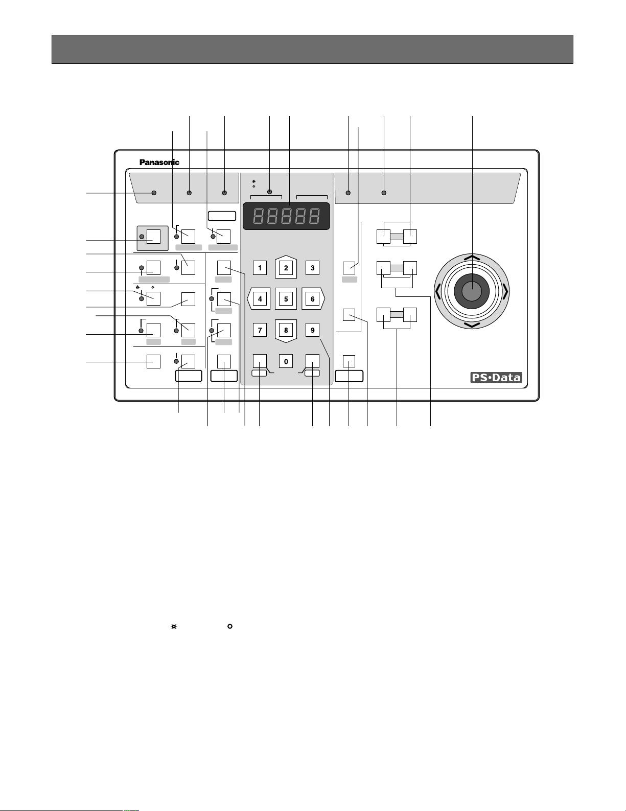
■ Rear View
DC 9V IN
DATAMODE
RISK OF ELECTRIC
SHOCK. DO NOT OPEN
RISQUE DE CHOCS ELECTROUES
NE PAS OUVRIR
0
9
8
7
6
5
4
3
2
1
#6
#7#5
CONTROLLER No.
#4
#3
#3 Controller Number switch (CONTROLLER No.)
This switch is used to set a controller number for the
System Controller to identify it in a system comprising
multiple System Controllers (See page 9). A system
may comprise up to four controllers.
Note: Keep the DC plug of the supplied AC adapter
disconnected from DC 9V Input Jack during controller number setting.
#4 Mode Selection switches (MODE)
The DIP switches are used to change the internal settings of the System Controller (see page 9).
#5 Data Ports (DATA)
These ports are used to exchange control data with the
WJ-MP204 Data Multiplex Unit via the supplied RS-485
cable.
#6 DC 9V Input Jack (DC 9V IN)
Jack for the DC plug of the supplied AC adapter.
#7 Clamper
The clamp fastens the power cord to the AC adapter.
Refer to the Operating Instructions of the Data Multiplex
Unit WJ-MP204 for further details.
NOTE
Page 9
9
INSTALLATIONS
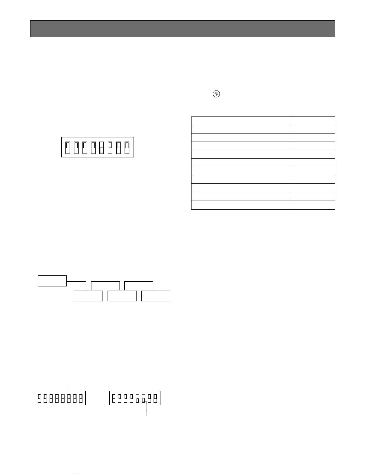
■ DIP Switch Setting
Set the DIP switches located on the rear of the system controller.
The initial factory settings are shown below.
Caution: Keep the power off before changing any DIP
switch setting.
MODE
12345678
OFF
ON
• DIP Switches 1, 2, 3, 4, 7, 8
These switches are reserved for mode setting.
Normally, keep them in the OFF position.
• DIP Switch 5
Used for termination setting.
Check that this switch is in the ON position.
Note: If two or more system controllers are used in a
system via RS-485, set SW5 on only one point at the
end position of the system controller to the ON position.
■ Controller Number Setting
Controller No. Switch of WV-CU360 Controller No.
0 Reserved
11
22
33
44
55
66
77
88
9 Reserved
Notes:
• Set the controller No. switch to No. 1 to use only one
system controller.
• Do not set the switch to No. 0 or 9 because these numbers are reserved.
• If a system has two or more system controllers, set different controller numbers to them. However, set the
controller No. switch in one of them to No.1.
• Keep the power off while setting controller numbers.
The set numbers are invalid if power is on.
CONTROLLER No.
0
9
8
7
6
5
4
3
2
1
The installation should be made by qualified service personnel or system installers only according to the following
instructions.
Turn the CONTROLLER No. (address
setting) switch till the arrow points the
desired number.
• DIP Switch 6
Used to select a mode for setup or normal operation.
Set DIP Switch 6 to OFF after completing the setup.
SW6 position for administrator setup mode: ON
SW6 position for operator mode: OFF
MODE
12345678
OFF
ON
MODE
12345678
OFF
ON
Operator mode
Administrator mode
System Unit
WV-CU360
Termination
OFF
Controller No. 3
Termination
OFF
Controller No. 2
Termination
ON
Controller No. 1
Termination
ON
WV-CU360 WV-CU360
Page 10
10
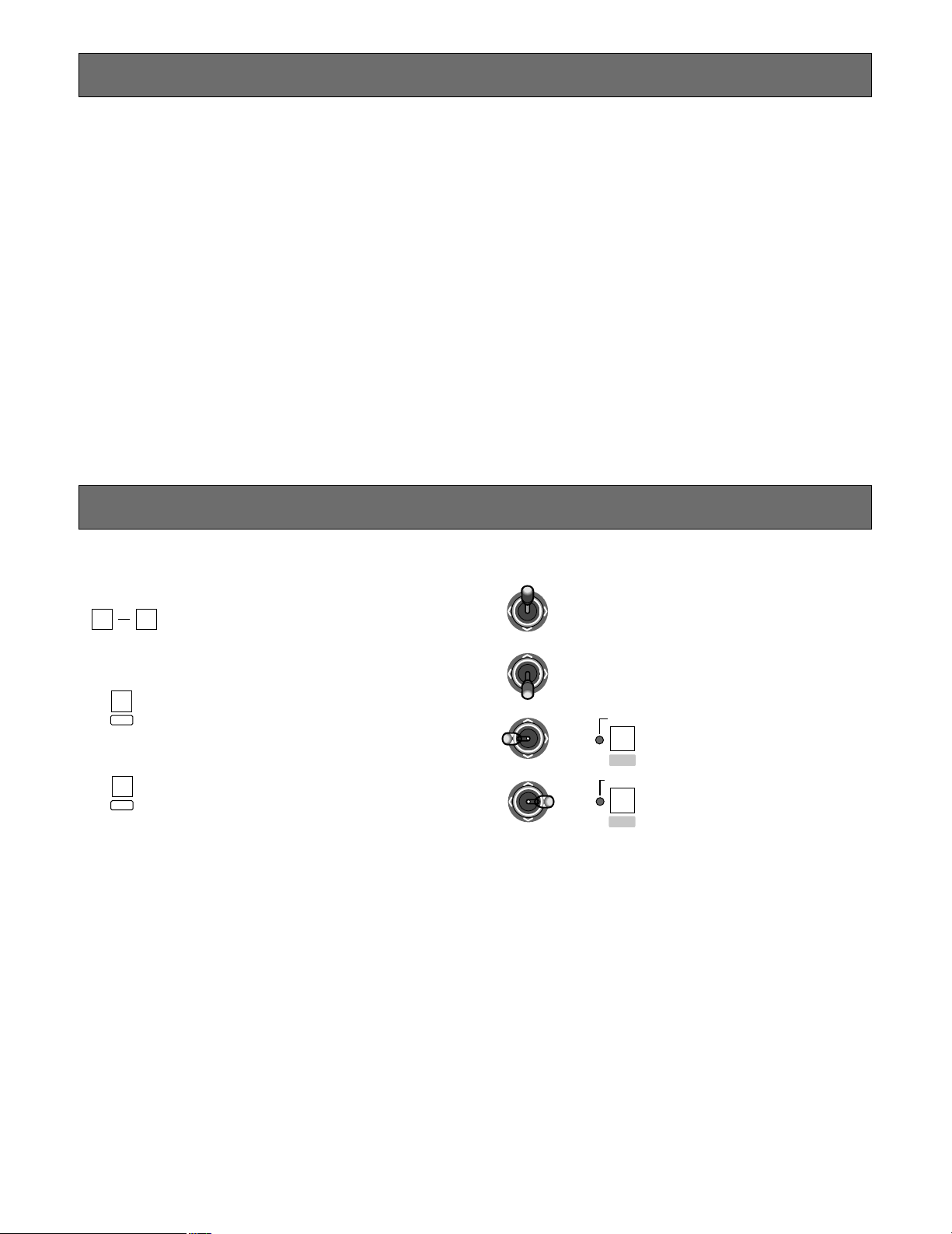
KEY FUNCTIONS OF SETUP MENU
Numeric buttons: To select modes and
parameters
CAM/SET button: To execute modes and
parameters
To enter a submenu
MON/ESC button: To return to the previous
menu
CAM
SET
DOWN
LR
UP
LR
UP
DOWN
R
UP
DOWN
LR
• Joystick Controller
Up: To select modes
Down: To select modes
Left: To decrease the parameter
Right: To increase the parameter
MON
ESC
EL-ZOOM
STILL
–
+
or
or
SETUP
The WV-CU360 can be set up as follows:
• WV-CU360 setup
• System unit setup for Panasonic Security Data mode
• System camera or combination camera setup (See page 28 and 29.)
■ Setup Procedures
1. DIP Switch Setting
2. Controller Number Setting
Use the controller number switch on the rear panel to set a controller number. To use two or more system controllers, connect them in a daisy-chain configuration.
3. Use the setup menu on the LED display of the System Controller WV-CU360. (See page 11.)
0
9
Page 11

11
SETUP MENU
■ Displaying the Setup Menu
1. Check that DIP Switch 6 is set to ON (Administrator
mode).
2. Connect the DC plug to the DC 9V IN jack and the AC
adapter to an AC outlet. The power of WV-CU360 is
supplied.
3. Check that the cameras and the other units are connected correctly and securely.
4. Switch the cameras and other system units on.
5. [SEtUP] appears.
6. Press the CAM/SET button. [˚ ˚ ˚ ˚ ˚] appears blinking.
7. Enter the Administrator Password. The default is
[12345]. Then press the CAM/SET button. [SPEEd]
appears.
8. You can proceed to another setting menu by moving
the joystick up or down.
9. Press the CAM/SET button.
The existing settings appear.
10. To change a parameter, press the CAM/SET button
after confirming the existing settings.
For details on changing the settings, see the corresponding parts of this page and the next.
11. Select a parameter by entering a number using numeric
buttons, by moving the joystick to the left or right, or by
pressing STILL/– button or EL ZOOM/+ button.
12. Press the CAM/SET button to set the entry. The set
value appears on the LED display. The set data is
saved in the memory of the WV-CU360. The setting is
completed. To return to the previous menu, press MON/
ESC button. To set another parameter, repeat procedures 8 to 12.
13. After disconnect the AC adapter from the AC outlet, set
Dip Switch 6 back to OFF (Operator mode).
Notes:
• If the administrator password fails in obtaining authorization, [Error] appears blinking for 2 seconds on the
LED display, followed by [SEtUP].
• After DIP Switch 6 is set to OFF (Operator mode), the
system is ready for setting up the cameras and the
other units . For details, see pages 28, 29 and 30.
• The Group Addresses of the WV-CU360 and System
Units on the Setup menu should be left as they are.
• All the settings must be compatible with the system
units connected.
• To return to the factory default settings, reset all (See
page 27).
● Baud Rate Setting (01)
1. Select [SPEEd] by moving the joystick up or down.
2. Press the CAM/SET button. [SP-96] appears.
3. Press the CAM/SET button.
4. Enter 3 (9 600), 4 (19 200), 1 (2 400), or 2 (4 800) using
numeric button. Or, select the desired baud rate 96
(9 600), 192 (19 200), 24 (2 400), or 48 (4 800) (bps) by
moving the joystick to the left or right.
The initial factory setting is 9600 bps.
5. Press the CAM/SET button.
6. To return to [SPEEd], press MON/ESC button.
Notes:
• The desired parameter is also selected by pressing
STILL/– button or EL-ZOOM/+ button.
• If the baud rate is set to 2 400 bps, instability of
data response may occur when the alarm is reset,
for example.
The Setup menu is used to set communication parameters and a user password etc. for system units compatible with
Panasonic Security Data mode.
■ Setup Menu
BAUD RATE
PARITY CHECK
WAIT TIME
CONTROLLER UNIT- GROUP ADDRESS
SYSTEM UNIT- GROUP ADDRESS
UNIT A NUMBER
UNIT B NUMBER
USER PASSWORD
ADMINISTRATOR (SUPER USER) PASSWORD
USER AUTHORIZATION (CERTIFICATION)
CAMERA CLEANING
UNIT CONNECTION TEST
Page 12

12
● Parity Check Setting (02)
1. Select [Prty] by moving the joystick up or down.
2. Press the CAM/SET button. [Pr-n] appears.
3. Press the CAM/SET button.
4. Enter 1 (n) or 2 (E) using numeric buttons. Or, select the
desired parity check n (NONE) or E (EVEN) by moving
the joystick to the left or right.
The initial factory setting is NONE.
5. Press the CAM/SET button.
6. To return to [Prty], press MON/ESC button.
Note: The desired parameter is also selected by press-
ing STILL/– button or EL-ZOOM/+ button.
● Wait Time Setting (03)
1. Select [WAIt] by moving the joystick up or down.
2. Press the CAM/SET button. [oFF] appears.
3. Press the CAM/SET button.
4. Enter 1 (OFF), 2 (100), 3 (200), 4 (400), or 5 (1 000)
using numeric buttons. Or, select the desired wait time
100, 200, 400, or 1 000 ms by moving the joystick to the
left or right. The initial factory setting is OFF (No retry).
5. Press the CAM/SET button.
6. To return to [WAIt], press MON/ESC button.
Note: The desired parameter is also selected by press-
ing STILL/– button or EL-ZOOM+ button.
● Controller Unit - Group Address Setting
[CU-gr] appears on the Setup menu, but leave the
default as it is.
● System Unit - Group Address Setting
[SU-gr] appears on the Setup menu, but leave the
default as it is.
● Unit Address Setting by UNIT A/UNIT
button (06)
1. Select [UA-no] by moving the joystick up or down.
2. Press the CAM/SET button. [A1-01] appears.
3. Enter an UNIT A number (1 to 9) using Numeric buttons.
4. Press the CAM/SET button.
5. Enter a 2-digit unit address (01 to 99) using Numeric
buttons.
6. Press the CAM/SET button.
7. To assign the other unit numbers, repeat procedures 36 after pressing CAM/SET button.
8. To return to [UA-no], press MON/ESC button.
Note: System units with unit addresses 1 to 9 are
assigned to the UNIT A/UNIT button in numerical
order A1 to A9 as initial factory settings. (See page
18).
● Unit Address Setting by UNIT B button (07)
1. Select [Ub-no] by moving the joystick up or down.
2. Press the CAM/SET button. [b1-01] appears.
3. Enter an UNIT B number (1 to 9) using Numeric buttons.
4. Press the CAM/SET button.
5. Enter a 2-digit unit address (01 to 99) using numeric
buttons. The initial factory setting is [b1-01].
6. Press the CAM/SET button.
7. To assign the other unit numbers, repeat procedures 36 after pressing CAM/SET button.
8. To return to [Ub-no], press MON/ESC button.
Note: System units with unit addresses 1 to 9 are
assigned to the UNIT B button in numerical order
B1 to B9 as initial factory settings (see page 18).
● User Password Setting (08)
1. Select [USrP] by moving the joystick up or down.
2. Press the CAM/SET button. [12345] appears.
3. Enter a 5-digit (00000 to 99999) using numeric buttons.
The LED blinks. The initial factory setting is [12345].
4. Press the CAM/SET button. The LED stops to blink.
5. To return to [USrP], press the MON/ESC button.
Note: If a 5-digit is not entered, the setting is invalid.
● Administrator (Super User) Password
Setting (09)
1. Select [SUSrP] by moving the joystick up or down.
2. Press the CAM/SET button. [12345] appears.
3. Enter a 5-digit (00000 to 99999) using numeric buttons.
The LED blinks. The initial factory setting is [12345].
4. Press the CAM/SET button. The LED stops to blink.
5. To return to [SUSrP], press the MON/ESC button.
Note: If a 5-digit is not entered, the setting is invalid.
● User Authorization(Certification)Setting(10)
1. Select [USr-C] by moving the joystick up or down.
2. Press the CAM/SET button. [UC-on] appears.
3. Press the CAM/SET button
4. Enter 2 (User Certification ON) or 1 (User Certification
OFF) using Numeric buttons. Or, select User
Certification ON or OFF by moving the joystick to the
left or right. The initial factory setting is User
Certification ON.
5. Press the CAM/SET button.
6. To return to [USr-C], press MON/ESC button.
Note: The desired parameter is also selected by press-
ing STILL/– button or EL-ZOOM/+ button.
● Camera Cleaning Setting (11)
Check that the power of the cameras and the other units
are switched on.
1. Select [CLEAn] by moving the joystick up or down.
2. Press the CAM/SET button [no-01] appears.
Page 13

13
3. Enter a camera number (01 to 199) for cleaning first
using Numeric buttons. The initial factory setting is [no01].
4. Press the CAM/SET button. Camera Cleaning starts.
5. The LED display shows a two-digit animations for cleaning on the left and a two-digit or a three-digit camera
numbers (01-199) on the right.
6. The last camera number appears when camera cleaning is over.
7. To return to the previous display, press the MON/ ESC
button.
Notes:
• To cancel the camera cleaning, press the MON/
ESC button.
• Camera surveillance is disabled while camera
cleaning continues.
• All cameras are automatically cleaned in order.
• Camera cleaning setting is valid only in cases
where a combination camera is connected to the
system.
● Unit Connection T est Setting (12)
Check that the power of the cameras and the other units
are switched on.
1. Select [UtESt] by moving the joystick up or down.
2. Press the CAM/SET button. [01-on] or [01-oF] appears.
3. Press the CAM/SET button. The unit connection test
starts (01-99).
4. The LED display shows a two-digit unit addresses on
the left and a two-digit animations for testing on the
right.
5. The last unit address appears when the unit test is over.
6. Press the CAM/SET button.
7. If you enter the unit address using numeric buttons after
finished it, you can confirm whether the unit is connected or not. Enter a 2-digit unit address to confirm the
connection. When [**-on] appears, the unit is connected. When [**-oF] (OFF) appears, the unit is not connected.
8. To return to the previous display, press the MON/ESC
button.
Notes:
•[**] displays the selected unit address (01-99).
• To cancel the unit connection test, press the MON/
ESC button.
• Camera surveillance is disabled while the unit connection test continues.
Page 14

14
SYSTEM CONNECTIONS
■ Connection to the WJ-MP204 Data Multiplex Units (Panasonic Security Data
Mode)
The supplied 6-conductor cable permits easy connection by simply plugging it into the data port (DATA) of the WJ-MP204
Data Multiplex Unit(s) and the other end into one end of the same port (DATA) of the System Controller.
If you are using locally purchased cables, make sure that they are 2-wire twisted pair shielded cables of data grade suited to
the RS-485. Low-grade cables will cause instability of system operation.
DC 9V IN
■ Connection with the AC Adapter
Insert the DC plug of the supplied AC adapter into the DC
9V input jack (DC 9V IN) on the System Controller. Then,
plug the AC adapter into an AC outlet.
SD RD
IN IN
CAMERA RS485
ABABG
VS/VDSPOT DATA
ALARM / REMOTE
MODE
SIGNAL GND
4321
OUT OUTINOUT
4321
TR
IN IN
CAMERA RS485
ABABG
VS/VDSPOT DATA
ALARM / REMOTE
MODE
SIGNAL GND
4321
OUT OUTINOUT
4321
Camera No. 1
Camera No. 2
Camera No. 3
Camera No. 4
Camera No. 5
Camera No. 6
Camera No. 7
Camera No. 8
VS/VD INPUT
SPOT OUT
SPOT SW OUT SPOT SW IN
SPOT IN
Unit Address 1Unit Address 2
WJ-MP204
WJ-MP204
Termination ON
Supplied 6-Conduntor Modular Cable
Up to four WV-CU360s
can be used in a system.
Monitor
MODE
VS/VD OUTPUT
4-Line
Panasonic Security
Data mode
Termination OFF
Panasonic Security
Data mode
4-Line
MODE
VD OUT
DC 9V IN
DATAMODECONTROLLER No.
0
9
8
7
6
5
4
3
2
1
0
9
8
7
6
5
4
3
2
1
Keep the OFF position
Keep the OFF position
Termination ON
Set the position to OFF
(for operator mode)
Controller No.1
Refer to DIP switch setting (See page 9)
CONTROLLER No.
Video Signal
RS-485 Signal
(Panasonic Security
Data mode)
:
:
Page 15

15
■ Connection in Panasonic Security Data Mode
● Basic Connection
Connect one of the DATA port on the System Controller to the same port on the WJ-MP204 with the supplied RS-485 cable (a
standard accessory to the system controller).
● Loop-through Connection
1. Plug the branch cable (optional accessory) into the DATA port on the Data Multiplex Unit WJ-MP204.
2. Plug the branch cable into the DATA port on the WJ-MP204, and connect one of the DATA port on the System Controller
with the RS-485 cable.
DATA
Data Multiplex Unit
WJ-MP204
System Controller
WV-CU360
DATA
RS-485 Cable
DATA
Data Multiplex Unit
WJ-MP204
Branch
Cable
System Controller
WV-CU360
DATA
RS-485 Cable
To use cables locally purchased, they must be of the data grade: BELDEN 9406 or equivalent. The pin assignments and
data flow are shown below.
1
6
1
6
No. No.
Name
Data Flow
1 1
GND
–
2 2
TX(B)
WV-CU360 → System Unit
3 3
TX(A)
WV-CU360 → System Unit
4 4
RX(B)
WV-CU360 ← System Unit
5 5
RX(A)
WV-CU360 ← System Unit
6 6
GND
–
WV-CU360 System Unit End
TX (B)
TX (A)
RX (B)
RX (A)
• Internal Diagram
Page 16

16
The operating instructions for using the System Controller in a system are described below. For further information, refer to the
Operating Instructions for the camera and for the individual system units.
BASIC OPERATING FLOW
OPERATING PROCEDURES
d
d
LOG IN
SYSTEM UNIT SELECTION
MONITOR SELECTION
LOG OUT
SYSTEM
OPERATION
• Alarm Reset
• Alarm Suspend
• Alarm Suspend
Cancel
SYSTEM UNIT
OPERATION
• System Unit Setup
• System Function
• Alarm Recall
CAMERA
OPERATION
• Camera Setup
• Pan/Tilt (Slow)
• Iris/Focus/Zoom
• Preset Position
• Home Position
• Switching of
Colour/Black &
White
• Auto Panning
• Camera Patrol
• Camera Patrol
Stop
• Camera Patrol
Learn
• Camera Function
• Wiper/Defroster
• Auxiliary Control
1/2
CAMERA
SELECTION
d
d
d
MONITOR
OPERATION
• Switching of VTR
and camera
• Multiscreen
Selection
• Still
• Electronic Zoom
• Sequence
• Sequence Pause
Page 17

17
SET
SET
ESC
UnauthorizedUnauthorized
OPERATE LOGIN ALARM
SET
Ready for user password entry
Authorized
User password entry
Blinks
The unit that is assigned to the UNIT A/UNIT
button as number 1 is selected automatically.
Indicates after authorized
Goes off after log out
LOGIN/LOGOUT
User authorization with password input is necessary for
access to the system controller. If [User Certification OFF]
is selected in the user authorization (certification) setting,
password input is not necessary because the system controller is automatically ready for operation when the power
is turned on.
■ LOG IN
1. Insert the DC plug into the DC 9V IN jack and connect
the AC adapter to an AC outlet.
2. The controller number, software version, and [LogIn]
appears in order on the LED display.
3. Press the CAM/SET button.
4. Enter a 5-digit user password with the Numeric buttons.
The password appears as each [–] digit.
Initial factory setting is [12345] (See page 12).
5. Press the CAM/SET button.
6. If the user password is successfully entered for user
authorization, LOGIN indicator lights up.
The unit that is assigned to the UNIT A/UNIT button as
number 1 is selected automatically.
If its entry has failed, [Error] appears on the display.
The display returns to [LogIn].
■ LOG OUT
1. Press the MON/ESC and CAM/SET buttons for about 2
seconds simultaneously.
2. [LogIn] appears on the display and the LOGIN indicator
goes off.
3. Disconnect the DC plug from the DC 9V IN jack and the
AC adapter from the AC outlet.
Note: If power remains on after finishing logout, the
alarm indicator and alarm suspend indicator keep
indicating the present system mode. The alarm indicator blinks in case of an alarm is activated after finishing logout. It changes to steady light when the
alarm is automatically reset.
Page 18

18
SYSTEM SELECTION
■ System Unit Selection
The following function is available only when connected to
System Units.
There are two ways of system unit selection. One is to enter
unit address using numeric buttons and the other is to
select a system unit by pressing the UNIT A/UNIT or UNIT
B button.
● Unit Selection
1. Check the unit number of each system unit.
2. Enter a unit number using numeric buttons.
MON
CAM
LOGOUT
ESC SET
3. Press the UNIT A/UNIT button after pressing the SHIFT
button.
SHIFT
UNIT A
UNIT
The selected unit number appears in the unit section of
the LED display.
The selected camera number appears in the camera
section of the LED display.
Notes:
• To confirm the selected unit number when the monitor number appears in the unit section of the LED
display, take procedure 3 or press MON/ESC button .
• If no unit is connected, [Err] appears a few seconds
after unit selecting operation is performed. In such
a case, repeat the above procedures after confirming the unit address.
• If the unit address of a system unit is unknown, consult the unit's administrator.
• When multiple system units such as Data Multiplex
Unit are connected to the System Controller and the
UNIT A/UNIT button is pressed, the camera number
on the controller's LED display will not agree with
the camera picture on the monitor.
In this case, select the monitor and camera as
described on the next page.
● Unit A/UNIT Button or UNIT B Button
Selection
The UNIT A/UNIT button or UNIT B button can be assigned
each till nine system units using Numeric buttons.
These buttons can be assigned to system units using the
Setup menu (See page 12).
If two or more system units are connected, the desired one
can be selected by pressing the corresponding numeric
button, then press the UNIT A/UNIT button or UNIT B button.
1. Enter an UNIT A or UNIT B number using numeric buttons.
This operation can be omitted if you select the unit
assigned to UNIT A number 1 or UNIT B number 1.
MON
CAM
LOGOUT
ESC SET
2. Press the UNIT A/UNIT button or the UNIT B button.
UNIT A
UNIT
The selected unit address appears in the unit section of
the LED display.
The selected camera number appears in the camera
section of the LED display.
Notes:
• In cases where the system unit is frequently used,
assign the UNIT A number [UA-no] or the UNIT B
number [Ub-no] (See page 12).
• If [A1-**] or [b1-**] is assigned to the system unit
as its UNIT A or UNIT B number, it can be selected
by simply taking procedure 2.
[**] displays the selected unit address (01-99)
• When multiple system units such as Data Multiplex
Unit are connected to the System Controller and the
UNIT A or UNIT B button is pressed, the camera
number on the controller's LED display will not
agree with the camera picture on the monitor.
In this case, select the monitor and camera as
described on the next page.
UNIT B
Page 19

19
■ Monitor Selection
Check that a monitor is connected to the system unit correctly and securely.
1. Select a system unit connected to the monitor.
2. Enter the monitor number using numeric buttons.
A monitor number is setup each system unit for output
to the monitors. For further information, refer to the
Operating Instructions for the individual units.
MON
CAM
LOGOUT
ESC SET
3. Press the MON/ESC button.
The selected monitor number appears in the monitor
section of the LED display. And then you can control
video operation for the selected monitor.
The selected camera number appears in the camera
section of the LED display.
Notes:
• To confirm the selected monitor number, simply
take procedure 3 when the unit address appears in
the monitor section of the LED display.
• The display of the unit section and the monitor section of the LED display changes alternately every
time the MON/ESC button is pressed.
• The setting is invalid if the unit in which a monitor
number has been set is not programmed.
• In the above case, repeat the same procedure after
confirming the monitor number. If you do not know
the monitor number, consult the administrator of it.
• When [--] appears in the monitor section of the LED
display, the selected system unit is not compatible
with the Monitor Selection.
• For further information, refer to the Operating Instructions for the system unit concerned.
MON
ESC
■ Camera Selection
1. To display the selected camera, select the desired system unit connected to cameras and the monitor.
2. Press the numeric buttons for the selected camera
number.
The camera number appears on the LED display.
3. Press the CAM/SET button to display the picture of the
selected camera.
The following function are available after selecting a camera.
• Pan/tilt
• Focus
• Zoom
• Iris
• Defroster ON/OFF (for camera housing)
• Wiper ON/OFF (for camera housing)
• Preset Position (for Combination Camera)
• Home position (for Combination Camera)
• Colour or B/W picture changing function (for
Combination Camera)
• Auto pan (for Combination Camera)
• Patrol Learn function (for Combination Camera)
• Camera functions (for Combination Camera)
Note: [--] appears in the camera section of the LED
display when an alarm is activated, when the multiscreen is displayed, or when sequence mode is on.
The following function is available only in cases where system units with the picture change function are connected.
• The currently selected camera can be replaced with the
camera of the next higher number by pressing the ELZOOM/+ button after pressing the SHIFT button.
• The currently selected camera can be replaced with the
camera of the next lower number by pressing the
STILL/– button after pressing the SHIFT button.
MON CAM
LOGOUT
ESC SET
Page 20

20
4. Press the EL-ZOOM/+ but-
ton again to zoom. The
zoom area can be moved
by the joystick in zoom
mode.
CONTROLLING SYSTEM FUNCTIONS
It is necessary to setup the system unit compatible with
Panasonic Security Data mode before using system
functions. For further information, refer to the Operating
Instructions for the system unit. You can also setup the system unit by this controller (See page 28). The operation differs depending on the system unit.
● Multiscreen Selection
The following function is available only in cases where system units with the multiscreen function are connected.
1. Select the desired system unit and monitor.
2. Press the MULTISCREEN SELECT button.
EL-ZOOM
+
3. Move the [+] mark into the
zoom area by moving the
joystick.
3. To cancel the still function, repeat procedures 1
and 2 above.
● Electronic Zoom Control
The following function is available only in cases where system units with the electronic zoom control function are connected.
1. Select the desired system unit, monitor and camera.
2. Press the EL-ZOOM/+ button. The EL-ZOOM/+ indica-
tor lights up and the [+] mark appears at the center of
the monitor screen.
MULTI SCREEN SELECT
¢
`
@
@
@
@
1
2
3 4
Example of Quad Picture
UP
LR
DOWN
3. A multiscreen appears. Each time the MULTISCREEN
SELECT button is pressed, the multiscreen changes.
The number of multiscreen pictures differ depending on
each system unit.
Note: This function is invalid unless a multiscreen moni-
tor is selected.
● Still Function
The following function is available only in cases where system units with the still function are connected.
1. Select the desired system unit, monitor and camera.
2. Press the STILL/– button to freeze the picture.
The STILL/– indicator lights up.
STILL
–
3. To cancel the still function, press the STILL/– button
again.
STILL
–
Notes:
• To freeze only a specific camera picture on the multiscreen
1. Select the desired system unit and monitor.
2. Select a camera number using numeric buttons.
3. Press the STILL/– button.
4. To cancel the still function, repeat procedures 2
and 3 above.
• To freeze all camera pictures on the multiscreen
1. Press numeric button 0.
2. Press the STILL/– button.
STILL
–
STILL
–
0
Page 21

21
The VTR/CAM indicator lights up. The playback picture
appears on the monitor.
Note: If the playback channel number etc. is not recog-
nized in winding the cassette fast forward or
rewinding it, the VTR/CAM indicator blinks.
3. To cancel the playback function, press the VTR/CAM
button again. The VTR/CAM indicator goes off. The
camera picture appears on the screen.
Note: To manually change playback pictures, set the
PLAYBACK AUTO ON in Setup menu of the system
unit to OFF.
● Sequence Function
The following function is available only in cases where a
system unit with the sequence function and sequence
pause function is connected.
1. Select the desired system unit and monitor.
2. Press the SEQUENCE/PATROL STOP button.
The SEQUENCE indicator lights up.
VTR CAM
5. To cancel the electronic zoom control, press the ELZOOM/+ button again. The EL-ZOOM/+ indicator goes
off.
● Displaying the Playback
The following function is available only in cases where a
system unit with the playback function is connected.
1. Select the desired system unit and monitor.
2. Press the VTR/CAM button.
3. To pause the sequence, press the SEQ PAUSE/SLOW
button.
SEQUENCE
PATROL
STOP
SEQ PAUSE
SLOW
5. To move the sequence one step backward, press the
STILL/– button.
STILL
–
3. Press the SETUP/FUNCTION button after pressing the
SHIFT button.
The system function corresponding to the entered number is controlled.
MON
CAM
LOGOUT
ESC SET
SHIFT
6. To cancel the sequence pause, press the SEQUENCE/
PATROL STOP button.
7. To cancel the sequence, select the desired camera.
Note: Procedures 3-5 apply only to system units with
the sequence pause function.
● System Function Control
The following function is available in cases where a system
unit capable of system function control with numeric buttons is connected. For further information, refer to the
Operating Instructions for the system unit used.
1. Select the desired system unit and monitor.
2. Select a system function number using numeric buttons.
FUNCTION
SETUP
EL-ZOOM
+
4. To move the sequence one step forward, press the ELZOOM/+ button.
Page 22

22
3. Press the ZOOM TELE button to optically bring the
object closer, or press the ZOOM WIDE button to optically widen the scene.
4. Press the IRIS CLOSE button to close the iris, or the
IRIS OPEN button to open the iris.
If the IRIS CLOSE and IRIS OPEN buttons are simulta-
neously pressed, the iris is reset to the default.
IRIS
CLOSE OPEN
IRIS RESET
WIDE TELE
ZOOM
■ Lens Control
The following functions are available to combination cameras with lens control capability.
1. Select the desired system unit, monitor and camera.
2. Press the FOCUS NEAR or FOCUS FAR button to
adjust the lens focus while watching the monitor.
If you are using a camera with an auto focus feature,
the lens focus can be automatically adjusted by pressing the FOCUS NEAR and FOCUS FAR buttons simultaneously.
NEAR FAR
FOCUS
AUTO FOCUS
CAMERA CONTROL FUNCTIONS
It is necessary to setup the camera before using camera
control functions. For further information, refer to the
Operating Instructions for the combination camera to setup
(See page 28). You can also setup it in camera setup menu
when you operate systems.
■ Pan/Tilt Control
The following function is available only to a combination
camera to which a pan/tilt head is connected to the system
unit.
1. Select the desired system unit, monitor and camera.
2. Move the pan/tilt head in the desired direction using the
joystick.
The camera can be moved in eight directions.
To move the pan/tilt head slow down, move the joystick
while holding down the SLOW button.
SEQ PAUSE
SLOW
Joystick
MON
CAM
LOGOUT
ESC SET
HOME/PRESET
PROGRAM
PRESET
The combination camera moves to the programmed
preset position and the picture of the camera in that
position appears on the monitor.
■ Operation of Combination Camera
It is necessary to setup the combination camera before
using the operation of it. For further information, refer to the
Operating Instructions for the combination camera to setup
(See page 28). You can setup in camera setup menu when
you operate systems.
● Changing Pictures of Preset Position
The following function is available only to cameras with the
preset function.
The preset function make the combination camera move to
the programmed preset position.
It is necessary to program preset positions in the combina-
tion camera beforehand.
1. Select the desired system unit, monitor and combination camera.
2. Select a preset number using numeric buttons, and
press the HOME/PRESET/PROGRAM PRESET button.
Page 23

23
● Changing the Pictures of Home Position
The following function is available only to cameras with the
preset function.
It is necessary to program the home position in the combination camera beforehand.
1. Select a system unit, monitor and combination camera.
2. Press the HOME/PRESET/PROGRAM PRESET button
to move the combination camera to the home position.
3. To cancel auto pan, move the joystick.
UP
LR
DOWN
The camera returns to the home position and the picture of
it appears on the monitor.
● Auto Pan
The following functions are available only to the camera
with a pan/tilt head specified for this operation.
It is necessary to program auto pan function in the combination camera beforehand.
1. Select the desired system unit, monitor and combination camera.
2. Press the AUTO/B/W button.
The auto panning activates according to the program in
the combination camera. The picture appears on the
monitor.
The following functions differ depending on the combination camera.
AUTO PAN ON or Functions that is set in combination camera: Simply press Numeric button 1 followed
by this button.
AUTO SORT ON: Press Numeric button 2 followed by
this button.
AUTO SEQ ON: Press Numeric button 3 followed by
this button.
RANDOM PAN ON: Press Numeric button 4 followed
by this button.
For further information, refer to the Operating
Instructions for the combination camera.
AUTO
B/W
● Changing to Black and White Pictures
The following function is available to the camera with a
colour-black and white switching function specified for this
operation.
1. Select the desired system unit, monitor and combination camera.
2. Press the AUTO/B/W button, after pressing the SHIFT
button, to change from colour to black and white picture. The black and white pictures appear on the monitor.
AUTO
B/W
SHIFT
3. To change black and white picture back to colour,
press the AUTO/B/W button again after pressing the
SHIFT button.
Note: When the changing black and white picture set-
ting is set to AUTO in the camera setup menu, this
function is disabled.
● Camera Patrol Function
The following function is available in cases where a combination camera with the camera patrol function is connected.
The camera patrol function enables the combination camera to learn joystick movements and zooming operation.
To program the camera patrol learning function, see page
29.
1. Select the desired combination camera.
2. Press the PATROL PLAY/PATROL LEARN button to
move the combination camera according to the data
saved in the memory.
PATROL PLAY
PATROL
LEARN
Camera patrol picture appears on the monitor.
3. To cancel patrol play function, move the joystick.
HOME/PRESET
PROGRAM
PRESET
UP
LR
DOWN
Page 24

24
MON
CAM
LOGOUT
ESC SET
CAM FUNCTION
SHIFT
CAM SETUP
• Electronic Shutter
The following function is available only to cameras with
the electronic shutter feature.
1. Select the desired combination camera.
2.. Press numeric buttons 1, 7, and 1.
MON
CAM
LOGOUT
ESC SET
3. Press the CAM SETUP/CAM FUNCTION button
after pressing the SHIFT button.
4. To cancel the electronic shutter function, press
numeric buttons 1, 7 and 2 in procedure 2 above.
5. To increase electronic shutter speed, press numeric
buttons 1, 7 and 3 in procedure 2 above.
6. To decrease electronic shutter speed, press numer-
ic buttons 1, 7 and 4 in procedure 2 above.
CAM FUNCTION
SHIFT
CAM SETUP
● Camera Cleaning Function
This function is used in cases of where the preset positions
of a combination camera have deviated. The function can
be set ready using the Setup menu. For further information,
refer to the description of Camera Cleaning setting in the
Setup menu. (See page 12.)
● Camera Functions
For further information, refer to the Operating Instructions
for the camera. Examples of camera functions are
described as follows.
• Super DynamicII
The following function is available only to cameras with
the Super DynamicII function.
1. Select the desired combination camera.
2. Press the numeric button 8 and 4.
3. Press the CAM SETUP/CAM FUNCTION button
after pressing the SHIFT button.
4. To cancel the Super DynamicII function, press
numeric buttons 8 and 5 in procedure 2 above.
Page 25

25
MON
CAM
LOGOUT
ESC SET
3. Press the CAM SETUP/CAM FUNCTION button
after pressing the SHIFT button.
CAM FUNCTION
SHIFT
CAM SETUP
4. To cancel the electronic sensitivity function, press
numeric buttons 1, 7 and 8 in procedure 2 above.
5. To increase electronic sensitivity, press numeric
buttons 1, 7 and 9 in procedure 2 above.
6. To decrease electronic sensitivity, press numeric
buttons 1, 8 and 0 in procedure 2 above.
• Camera Restart
The following function is available only to cameras with
the camera restart function.
1. Select the desired combination camera.
2. Press numeric buttons 1, 0 and 0.
3. Press the CAM SETUP/CAM FUNCTION button
after pressing the SHIFT button.
CAM FUNCTION
SHIFT
CAM SETUP
MON
CAM
LOGOUT
ESC SET
• Automatic Gain Control
The following function is available only to cameras with
the AGC feature.
1. Select the desired combination camera.
2. Press numeric buttons 1, 7 and 5.
3. Press the CAM SETUP/CAM FUNCTION button
after pressing the SHIFT button.
MON
CAM
LOGOUT
ESC SET
CAM FUNCTION
SHIFT
CAM SETUP
4. To cancel the AGC function, press numeric buttons
1, 7 and 6 in procedure 2 above.
• Electronic Sensitivity Up
The following function is available only to cameras with
the electronic sensitivity function.
1. Select the desired combination camera.
2. Press numeric buttons 1, 7 and 7.
Page 26

26
■ Camera Housing Control
● Defroster Control
The following function is available only in cases where the
camera housing connected has the defroster control function.
1. Select the desired system unit, monitor and camera.
2. Press the DEF/AUX 2 button to operate the defroster for
the selected camera.
The DEF/AUX 2 indicator lights up.
WIPER
AUX 1
DEF
AUX 2
3. To cancel the defroster control function, press the
DEF/AUX 2 button.
The DEF/AUX 2 indicator goes off.
DEF
AUX 2
DEF
WIPER
AUX 1
AUX 2
SHIFT
3. To cancel the auxiliary control function, press the
WIPER/AUX 1 or DEF/AUX 2 button after pressing the
SHIFT button.
Note: The auxiliary control function is invalid while the
zoom function or the pan/tilt head is in operation.
■ External Device Control
● Auxiliary Control
The following function is available only in cases where
external devices are connected.
1. Select the desired system unit connected to an external
device, a monitor and camera.
2. Press the WIPER/AUX 1 or DEF/AUX 2 button after
pressing the SHIFT button, to enable or disable the
user switch on the receiver. The WIPER/AUX 1 or
DEF/AUX 2 indicator lights up.
● Wiper Control
The following function is available only in cases where the
camera housing connected has the wiper control function.
1. Select the desired system unit, monitor and camera.
2. Press the WIPER/AUX 1 button to operate the wiper on
the selected camera.
The WIPER/AUX 1 indicator lights up.
3. To cancel the wiper control function, press the WIPER/
AUX 1 button. The WIPER/AUX 1 indicator goes off.
Caution: To prevent early wiper wear, be sure to turn
off the wiper whenever it is not needed, or before
selecting another camera for viewing.
Page 27

27
ALARM CONTROL FUNCTIONS
■ Alarm Operation
When the WV-CU360 receives an alarm signal from a system unit, the alarm indicator blinks.
The alarm indicator changes from blinking to steady light
when the alarm is automatically reset.
The camera number [---] appears in the camera section of
the LED display.
■ Alarm Reset
1. Press the ALM RESET/ALM RECALL button.
ALM RESET
ALM RECALL
The alarm indicator goes off.
Notes:
• Alarm reset operations (including auto reset) apply
to the whole system comprising the multiple system
units, not to a selected unit alone.
• Alarm reset mode differs depending on the system
unit connected to the WV-CU360 when an alarm is
reset.
• Confirm that the SHIFT button is released.
■ Alarm Suspend
The following function is available only in cases where system units with the alarm suspend function are connected.
1. Press ALM SUSPEND button. The ALM SUSPEND
indicator lights up.
1 2 3
4 6
7 8 9
0
5
PROGRAM
PRESET
ESC
HOME
SET
PRESET
The System Controller WV-CU360 can be reset to the
default settings as follows:
1. Turn the controller's power off (unplug the DC plug of
the AC adapter).
2. Plug in the DC plug of the AC adapter connected, while
pressing numeric buttons 2, 4 and 6 simultaneously.
3. When all indicators light up, resetting is completed.
Note: Keep the DC plug of the supplied AC adapter
connected to the DC 9V Input Jack until all resetting
completes.
ALM
SUSPEND
2. To cancel the alarm suspend function, press the ALM
SUSPEND button again.
Note: Alarm suspension applies to the whole system
comprising the multiple system units, not to a
selected unit alone.
■ Alarm Recall
The following function is available only in cases where system units with the alarm recall function are connected.
1. Select the desired system unit and monitor.
2. Press ALM RESET/ALM RECALL button after pressing
the SHIFT button. The ALM RECALL indicator lights
up. An alarm recall log appears on the monitor.
3. To cancel the alarm recall function, press the ALM
RESET/ALM RECALL button after pressing the SHIFT
button again.
ALL RESET
Input alarm is ignored even after the ALM SUSPEND is
set.
ALM
SUSPEND
ALM RESET
SHIFT
ALM RECALL
Page 28

28
SYSTEM UNIT AND CAMERA SETUP
You can setup the system unit and the camera with the
setup menu by this controller.
For further information, refer to the Operating Instructions
for system units and the individual combination cameras.
● System Unit Setup
1. Select the desired system unit compatible with
Panasonic Security Data mode.
2. Press the SETUP/FUNCTION button for more than 2
seconds. The SETUP indicator lights up.
The Setup menu for the system unit appears on the
monitor.
FUNCTION
SETUP
Example of Setup Menu in WJ-MP204
WJ-MP204 SETUP MENU x.xx
COMMUNICATION
SYSTEM
3. To complete the setup, press the SETUP/FUNCTION
button for 2 seconds or more.
The SETUP indicator goes off.
Notes:
• For the system unit defaults, refer to the Operating
Instructions for the individual system units.
• If you change the default baud rate or parity check, the
system unit setup function is disabled.
• The setup for system units differ depending on each
unit. Refer to the Operating Instructions for each unit
before setting up them.
Keys Used for System Unit with Setup Menu
Note: The key functions differ from one system to another.
Refer to the Operating Instructions for each unit before
operating its keys.
● Camera Setup
1. Select the desired camera.
2. Press the CAM SETUP/CAM FUNCTION button for 2
seconds or more to access the Camera Setup menu.
The CAM SETUP indicator lights up.
3. Select an item and parameter by pressing numeric buttons 2, 4, 6 and 8.
CAM FUNCTION
CAM SETUP
*** SET UP MENU ***
PRESET 1*
MAP
HOME POSITION
SELF RETURN
AUTO MODE
AUTO PAN KEY
DIGITAL FLIP
LOCAL/REMOTE
SPECIAL1
CAMERA
RS485 SET UP
15
10MIN
AUTO PAN
SEQ
OFF
LOCAL
(Example of Camera Setup menu)
MON
CAM
LOGOUT
ESC SET
4. Press the CAM/SET button to execute the parameter or
enter a submenu.
MON
CAM
LOGOUT
ESC SET
5. To return to the previous menu, press the MON/ESC
button.
6. Press the CAM SETUP/CAM FUNCTION button for 2
seconds or more to complete the camera setup.
To move the cursor.
To select a parameter.
To execute the parameter or
To enter a submenu
To return to the previous menu
CAM
SET
MON
ESC
DOWN
LR
UP
LR
EL-ZOOM
STILL
–
+
Page 29

29
7. Move the cursor to [SPECIAL] on the Setup menu, and
press numeric buttons 4 and 6 simultaneously for 2
seconds or more to display the special menu.
8. Move the cursor to [CAMERA RESET]* on the Setup
menu, and press buttons 4, 5 and 6 simultaneously to
cancel all the functions to the defaults.
* The menu to reset the camera functions differs
depending on the camera:
[SPECIAL] for the WV-CS650, [SPECIAL 2] for the WVCS850, and [END] for fixed cameras etc.
Caution: If camera setup is started using the buttons
on the camera, all future operations for setup must
be performed using the buttons on the camera.
If camera setup is started using the System
Controller, all future operations for setup must be
performed using the same controller.
Note: For further information, refer to the Operating
Instructions for the selected camera.
Keys Used for camera with Setup Menu
[LEARNING] appears on the monitor.
3. Patrol play the combination camera by using the joystick or zoom buttons etc. This enables the combination
camera to learn.
Maximum learning time is 30 seconds.
4. To stop the learning, press the SEQUENCE/PATROL
STOP button while holding down the PROGRAM/CAM
SETUP/CAM FUNCTION button.
The learning program
• Pan/Tilt (Joystick)
• Iris (Open/Close)
• Focus (Far/Near)
• Zoom (Tele/Wide)
• Preset Position
Note: The learning program differs depending on the cam-
era. For further information, refer to the Operating
Instructions for the camera to check the operations covered by the learning program before operating the camera.
[LEARNING] disappears on the monitor.
LEARNING
2
8
4
6
To move the cursor.
To select a parameter.
To execute the mode or
To enter a submenu
To return to the previous menu
CAM
SET
MON
ESC
● Camera Patrol Learning for Camera Patrol
Operation
There are two ways of setting camera patrol learning.
One is to set up using the Camera Setup menu and the
other is to set up while operating the camera.
Follow the procedures below to set up while operating a
combination camera.
1. Select the desired system unit, monitor and combination camera.
2. Press the PATROL PLAY/PATROL LEARN button
while holding down the PROGRAM/CAM SETUP/CAM
FUNCTION button.
PATROL PLAY
PATROL
LEARN
CAM FUNCTION
CAM SETUP
PROGRAM
SEQUENCE
PATROL
STOP
CAM FUNCTION
CAM SETUP
PROGRAM
Page 30

30
4. Press the HOME/PRESET/PROGRAM PRESET button
while holding down the PROGRAM/CAM SETUP/CAM
FUNCTION button.
The actual camera position of the preset number programmed in procedure 4 is learned as preset.
● Preset Position Setting
There are two ways of presetting camera positions.
One is to preset positions using the Camera Setup
menu of the combination camera and the other is to
preset them by operating the System Controller.
The following function is available in cases where a
selected combination camera compatible with each
function.
1. Select the desired system unit, monitor and camera.
2. Move the combination camera at preset position by
using the joystick, or zoom buttons etc.
3. Press the numeric button for the preset position to be
learned.
The preset position number is learned upon its entry.
UP
LR
DOWN
MON
CAM
LOGOUT
ESC SET
HOME/PRESET
PROGRAM
PRESET
CAM FUNCTION
CAM SETUP
PROGRAM
The preset data program
• Pan/Tilt (Joystick)
• Iris (Open/Close)
• Focus (Far/Near)
• Zoom (Tele/Wide)
Note: The preset data program differ depending on the
camera. For further information, refer to the Operating
Instructions for the camera to check the operations covered by the preset data program before operating the
camera.
Page 31

31
<Controller>
Power Source: 9 V DC, 400 mA (Use the supplied AC Adapter only)
Data Output/Input Port: 6-conductor modular jack (RS-485, Full Duplex)
Switching Functions (WJ-MP204): Camera selection
Switching Functions Monitor Selection/Switching of Live and Playback/Changing of the num-
ber of the Multiscreen Picture/Still/Electronic Zoom/Sequence
Controller Number 1-8 (Rotary Switch)
Unit Address Selection: 1-99
Monitor Number Selection: 1-99
Camera Number Selection: 1-199
Lens Functions: Iris: Open/Close/Preset (only with DC control lens)
Focus: Near/Far/Auto Focus
Zoom: Wide/Tele
Housing: Defroster: On/Off
Wiper: On/Off
Auxiliary 1: On/Off
Auxiliary 2: On/Off
Pan/Tilt: Manual Pan: Right/Left
Manual Tilt: Up/Down
Auto Pan, Auto Sort, Auto Sequence, Random Pan, Preset Position, Home
Position, Camera Patrol
Other Camera Controls: Camera Setup
Camera Function
System Operation: Camera selection
Alarm (Display/Suspend/Recall/Reset)
Setup
Ambient Operating Temperature: –10˚C - +50˚C (14˚F - 122˚F)
Ambient Operating Humidity: Less than 90%
Dimensions: 300 (W) mm x 74 (H) mm x 177 (D) mm
[11-13/16” (W) x 2-15/16” (H) x 6 15/16” (D)]
Weight: 1.3 kg (2.9 lbs.)
<AC Adapter>
Input Input
Power Source: 230 V AC, 50 Hz Power Source: 230 V - 240 V AC, 50 Hz
Power Consumption: 12 VA Power Consumption: 12 VA
Output or Output
Power Source: 9 V DC Power Source: 9 V DC
Power Consumption: 400 mA Power Consumption: 400 mA
Dimensions and weight are approximate.
Specifications are subject to change without notice.
SPECIFICATIONS
STANDARD ACCESSORIES
AC Adapter......................................................................1 pc.
6-conductor Modular Cable Assembly............................1 pc.
Page 32

NM1099-1040 YWV8QA5363BN Printed in Japan
N 19 Gedruckt in Japan
Imprimé au Japon
Impreso en Japón
© Matsushita Communication Industrial Co., Ltd. 2000
Matsushita Electric Industrial Co., Ltd.
Central P.O. Box 288, Osaka 530-91, Japan
 Loading...