

Panasonic WV-CU161C/G, WV-CU161C/B Operating Instructions Manual
Before attempting to connect or operate this product,
please read these instructions carefully and save this manual for future use.
The model number is abbreviated in some descriptions in this manual.
Model No. WV-CU161C/B
WV-CU161C/G
System Controller
Operating Instructions
S
y
s
te
m
C
o
n
tro
lle
r W
V
-C
U
C
5
4
1
S
H
I
F
T
ESC
A
L
A
R
M
A
L
A
R
M
O
P
E
R
A
T
E
R
E
S
E
T
CAMERA
SETUP
S
E
T
U
P
S
L
O
W
P
R
O
G
R
A
M
S
E
T
P
R
E
S
E
T
H
O
M
E
W
ID
E
W
IP
E
R
AUX 1
AUX 2
D
E
F
P
A
T
R
O
L
P
L
A
Y
C
L
O
S
E
N
E
A
R
F
A
R
L
R
UP
DOWN
O
P
E
N
T
E
L
E
Z
O
O
M
I
R
I
S
F
O
C
U
S
P
A
T
R
O
L
S
T
O
P
P
A
T
R
O
L
L
E
A
R
N
A
U
T
O
B
/
W
A
U
T
O
F
O
C
U
S
IRIS RESET
P
R
O
G
R
A
M
P
R
E
S
E
T
CAM
ERA
FUNCTION
SUSPEND
2
0
6
3
9
8
7
FRANÇAIS
DEUTSCH
ENGLISHESPAÑOL
ITALIANO
2
ENGLISH VERSION
The serial number of this product may be found on the
bottom of the unit.
You should note the serial number of this unit in the
space provided and retain this book as a permanent
record of your purchase to aid identification in the event
of theft.
Model No.
Serial No.
The lightning flash with arrowhead symbol, within an equilateral triangle, is
interned to alert the user to the presence
of uninsulated "dangerous voltage" within
the product's enclosure that may be of
sufficient magnitude to constitute a risk of
electric shock to persons.
The exclamation point within an equilateral triangle is intended to alert the user
to the presence of important operating
and maintenance (servicing) instructions
in the literature accompanying the appliance.
Power disconnection. Unit with or without
ON-OFF switches have power supplied
to the unit whenever the power cord is
inserted into the power source; however,
the unit is operational only when the ONOFF switch is in the ON position. The
power cord is the main power disconnect
for all units.
CAUTION: TO REDUCE THE RISK OF ELECTRIC SHOCK,
DO NOT REMOVE COVER (OR BACK).
NO USER-SERVICEABLE PARTS INSIDE.
REFER SERVICING TO QUALIFIED SERVICE PERSONNEL.
CAUTION
RISK OF ELECTRIC SHOCK
DO NOT OPEN
FOR YOUR SAFETY PLEASE READ THE FOLLOWING TEXT CAREFULLY.
This appliance is supplied with a moulded three pin mains plug for your
safety and convenience.
A 13 amp fuse is fitted in this plug.
Should the fuse need to be replaced please ensure that the replacement
fuse has a rating of 13 amp and that it is approved by ASTA or BSI to
BS1362.
Check for the ASTA mark
H or the BSI mark G on the body of the
fuse.
If the plug contains a removable fuse cover you must ensure that it is
refitted when the fuse is replaced.
If you lose the fuse cover the plug must not be used until a replacement
cover is obtained.
A replacement fuse cover can be purchased from your local Panasonic
Dealer.
IF THE FITTED MOULDED PLUG IS UNSUITABLE FOR THE SOCKET OUTLET IN YOUR HOME THEN THE FUSE SHOULD BE
REMOVED AND THE PLUG CUT OFF AND DISPOSED OF SAFELY.
THERE IS A DANGER OF SEVERE ELECTRICAL SHOCK IF THE
CUT OFF PLUG IS INSERTED INTO ANY 13 AMP SOCKET.
If a new plug is to be fitted please observe the wiring code as shown
below.
If in any doubt please consult a qualified electrician.
WARNING: This apparatus must be earthed.
IMPORTANT
The wires in this mains lead are coloured in accordance with the following code.
Green-and-yellow: Earth
Blue: Neutral
Brown: Live
As the colours of the wire in the mains lead of this appliance may not
correspond with the coloured markings identifying the terminals in your
plug, proceed as follows.
The wire which is coloured green-and-yellow must be connected to
the terminal in the plug which is marked with the letter E or by the earth
symbol
I or coloured green or green-and-yellow.
The wire which is coloured blue must be connected to the terminal in
the plug which is marked with the letter N or coloured black.
The wire which is coloured brown
must be connected to the terminal in
the plug which is marked with the letter L or coloured red.
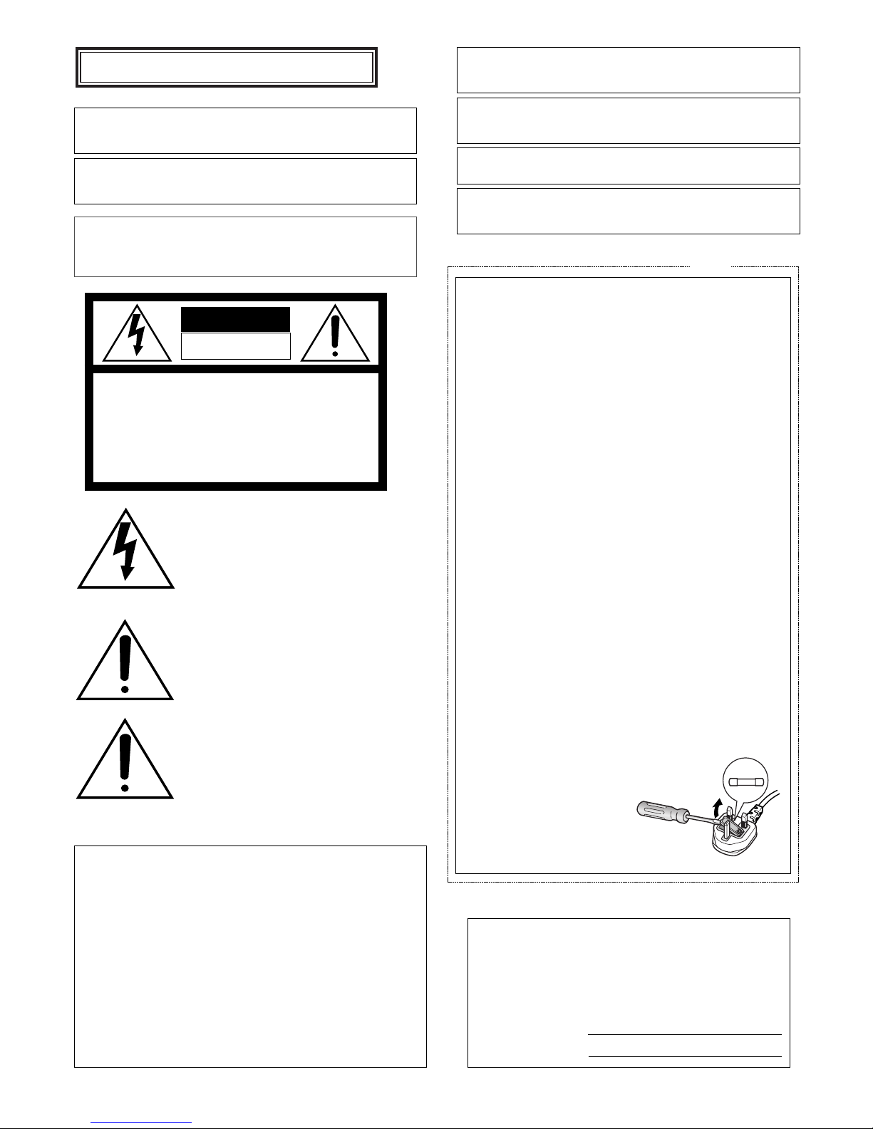
How to replace the fuse
Open the fuse compartment with
a screwdriver and replace the fuse
and fuse cover.
For U.K.
FUSE
WARNING:
• This apparatus must be earthed.
• Apparatus shall be connected to a mains socket outlet with a
protective earthing connection.
• The mains plug or an appliance coupler shall remain readily
operable.
• To prevent fire or electric shock hazard, do not expose this
apparatus to rain or moisture.
• The apparatus should not be exposed to dripping or splashing and that no objects filled with liquids, such as vases,
should be placed on the apparatus.
• All work related to the installation of this product should be
made by qualified service personnel or system installers.
• The connections should comply with local electrical code.
CAUTION:
Before attempting to connect or operate this product, please
read the label on the bottom.
Vi erklærer os eneansvarlige for, at dette produkt, som denne deklaration
omhandler, er i overensstemmelse med standarder eller andre normative
dokumenter i følge bestemmelserne i direktivene 2006/95/EC og
2004/108/EC.
Vi deklarerar härmed vårt fulla ansvar för att den produkt till vilken denna
deklaration hänvisar är i överensstämmelse med de standarder eller andra
normativa dokument som framställs i direktiv nr 2006/95/EC och
2004/108/EC.
Ilmoitamme yksinomaisella vastuullamme, että tuote, jota tämä ilmoitus
koskee, noudattaa seuraavia standardeja tai muita ohjeellisia asiakirjoja,
jotka noudattavat direktiivien 2006/95/EC ja 2004/108/EC säädöksiä.
Vi erklærer oss alene ansvarlige for at produktet som denne erklæringen
gjelder for, er i overensstemmelse med følgende normer eller andre
normgivende dokumenter som følger bestemmelsene i direktivene
2006/95/EC og 2004/108/EC.
Wij verklaren als enige aansprakelijke, dat het product waarop deze
verklaring betrekking heeft, voldoet aan de volgende normen of andere
normatieve documenten, overeenkomstig de bepalingen van Richtlijnen
2006/95/EC en 2004/108/EC.
We declare under our sole responsibility that the product to which this
declaration relates is in conformity with the standards or other normative
documents following the provisions of Directives 2006/95/EC and
2004/108/EC.

3
CONTENTS
Preface ............................................................................................................................................ 4
Features .......................................................................................................................................... 4
Limitation of Liability ........................................................................................................................ 5
Disclaimer of Warranty .................................................................................................................... 5
Precautions ...................................................................................................................................... 5
Major Operating Controls and Their Functions ............................................................................... 6
■ Front View ................................................................................................................................. 6
■ Rear View ................................................................................................................................. 8
Installation ....................................................................................................................................... 9
■ Mounting in the Rack ............................................................................................................... 9
Connection & Setting ...................................................................................................................... 10
■ System Connection .................................................................................................................. 10
■ Connection with a Time Lapse VTR ......................................................................................... 13
■ Cable-loss Compensation Setting ............................................................................................ 13
■ RS-485 Connection .................................................................................................................. 14
■ Switch Setting ........................................................................................................................... 15
Setup Menu ..................................................................................................................................... 18
■ Displaying the Setup Menu ......................................................................................................18
■ Buttons & Controls used in the Setup Menu ............................................................................ 18
■ Alarm Setup .............................................................................................................................. 19
■ System Setup ........................................................................................................................... 21
■ Preset Data Loading ................................................................................................................ 21
■ Communication Setup .............................................................................................................. 24
Operating Procedures .................................................................................................................... 25
CAMERA CONTROL FUNCTIONS ............................................................................................... 25
■ Pan/Tilt Control ......................................................................................................................... 25
■ Lens Control ............................................................................................................................. 25
■ Operation of Combination Camera .......................................................................................... 26
■ Camera Housing Control .......................................................................................................... 29
■ External Device Control ............................................................................................................ 29
ALARM CONTROL FUNCTIONS ................................................................................................. 30
■ Alarm Operation ....................................................................................................................... 30
■ Alarm Reset .............................................................................................................................. 30
■ Alarm Suspend ......................................................................................................................... 30
CAMERA SETUP .......................................................................................................................... 31
All Reset .......................................................................................................................................... 33
Specifications .................................................................................................................................. 34
Standard Accessories ..................................................................................................................... 34
ENGLISH

4
Preface
The WV-CU161C System Controller is designed for one-to-one use with a Combination Camera or WV-RC100/WV-RC150
Receiver that is provided with camera control functions. You can operate the pan/tilt head, lens and patrol play function from
the controller in normal operations. The camera setup upload/download and other functions are also available on the setup
menus. The distance between the camera and controller may vary depending on the system. The controller can transmit camera control commands via an RS-485 line or a coaxial cable. A time lapse VTR (VCR), alarm sensors and a video monitor can
be connected to the controller.
Features
The WV-CU161C offers the following features when used with a combination camera.
• Pan/tilt control: Manual Pan/Tilt Slow ON/OFF, Auto Panning ON/OFF, Sequence Sort/Random
• Lens control: Iris, Zoom, Focus with Auto-focus
• Preset position memories: Up to 64 positions including HOME
• Patrol: Learning/Play
• Image selection: Colour/Black and White
• Alarm control: Suspension ON/OFF, Reset
Note: The WV-CU161C will not perform audio communications even if an audio board is installed in the connected Receiver.

5
Precautions
• Refer all work related to the installation of this
appliance to qualified service personnel or system
installers.
• Do not block the ventilation opening or slots on the
cover.
To prevent the appliance from overheating, place it at
least 5 cm {2 inches} away from the wall.
• Do not drop metallic parts through slots.
This could permanently damage the appliance. Turn
the power off immediately and contact qualified service
personnel for service.
• Do not attempt to disassemble the appliance.
To prevent electric shock, do not remove screws or
covers.
There are no user-serviceable parts inside. Contact
qualified service personnel for maintenance.
• Do not expose nor operate the appliance in
wet/damp conditions.
Take immediate action if the appliance gets wet. Refer
servicing to qualified service personnel. Moisture could
damage the appliance and also cause electric shocks.
• Handle the appliance with care.
Do not strike or shake, as this may damage the appliance.
• Do not expose the appliance to water or moisture.
Do not try to operate it in wet areas.
Take immediate action if the appliance gets wet. Turn
the power off and refer servicing to qualified service
personnel. Moisture can damage the appliance and
also cause electric shocks.
• Do not use strong or abrasive detergents when
cleaning the appliance body.
Use a dry cloth to clean the appliance when it is dirty.
When the dirt is hard to remove, use a mild detergent
and wipe gently.
• Do not operate the appliance beyond its specified
temperature, humidity, or power source ratings.
Use the appliance under conditions where temperatures are between –10 °C and + 50 °C {14 °F to
122 °F}, and humidity below 90 %.
The input power source for this appliance is 220 V 240 V AC, 50 Hz.
• Only use the appliance indoors.
Do not install it in places where the appliance is
exposed to sunlight for long periods of time or near air
conditioning equipment. This will cause deformation,
discoloration, breakdown or malfunction.
Limitation of Liability
THIS PUBLICATION IS PROVIDED "AS IS" WITHOUT WARRANTY OF ANY KIND, EITHER EXPRESS OR IMPLIED,
INCLUDING BUT NOT LIMITED TO, THE IMPLIED WARRANTIES OF MERCHANTABILITY, FITNESS FOR ANY PARTICULAR PURPOSE, OR NON-INFRINGEMENT OF THE
THIRD PARTY’S RIGHT.
THIS PUBLICATION COULD INCLUDE TECHNICAL INACCURACIES OR TYPOGRAPHICAL ERRORS. CHANGES
ARE ADDED TO THE INFORMATION HEREIN, AT ANY
TIME, FOR THE IMPROVEMENTS OF THIS PUBLICATION
AND/OR THE CORRESPONDING PRODUCT (S).
Disclaimer of Warranty
IN NO EVENT SHALL Panasonic Corporation BE LIABLE
TO ANY PARTY OR ANY PERSON, EXCEPT FOR CERTAIN
WARRANTY PROGRAM OFFERED BY THE LOCAL DEALER OF PANASONIC, FOR THE CASES INCLUDING BUT
NOT LIMITED TO BELOW:
(1) ANY DAMAGE AND LOSS, INCLUDING WITHOUT LIM-
ITATION, DIRECT OR INDIRECT, SPECIAL, CONSEQUENTIAL OR EXEMPLARY, ARISING OUT OF OR
RELATING TO THE PRODUCT;
(2) PERSONAL INJURY OR ANY DAMAGE CAUSED BY
INAPPROPRIATE USE OR NEGLIGENT OPERATION
OF THE USER;
(3) UNAUTHORIZED DISASSEMBLE, REPAIR OR MODIFI-
CATION OF THE PRODUCT BY THE USER;
(4) INCONVENIENCE OR ANY LOSS ARISING WHEN
IMAGES ARE NOT DISPLAYED, DUE TO ANY REASON
OR CAUSE INCLUDING ANY FAILURE OR PROBLEM
OF THE PRODUCT;
(5) ANY PROBLEM, CONSEQUENTIAL INCONVENIENCE,
OR LOSS OR DAMAGE, ARISING OUT OF THE SYSTEM COMBINED BY THE DEVICES OF THIRD PARTY.
6
Major Operating Controls and Their Functions
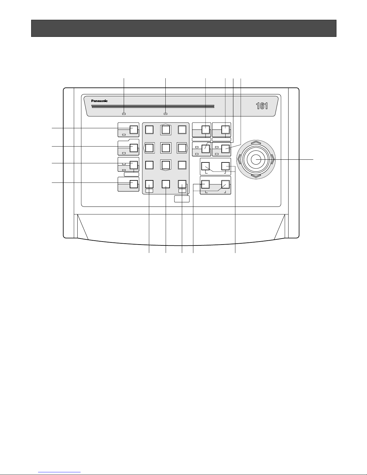
■ Front View
q Operate Indicator (OPERATE)
Lights up while the System Controller power is on.
w Alarm Indicator (ALARM)
Blinks when an alarm is activated.
The blink changes to a steady light when the alarm is
automatically reset.
Press the ALARM RESET button to turn the indicator off.
e Auto Panning/Black and White Selection/Patrol Stop
Button (AUTO/B/W/PATROL STOP)
AUTO: Pressing this button will activate the auto pan-
ning function of cameras that are provided with this
feature.
B/W: Pressing this while the SHIFT indicator is lit will
display the picture in black and white on the monitor.
PATROL STOP: Pressing this button while holding
down the CAMERA SETUP button will stop programming the camera patrol learning function.
The four following Auto Panning modes can be selected
by pressing the AUTO button in combination with buttons 1 to 4
For further information, refer to the Operating Instructions for the individual combination cameras.
AUTO PAN ON or Functions set on a combination
camera:
Simply press this button or press button 1 and
then this button.
AUTO SORT ON: Press button 2 and then this button.
AUTO SEQ ON: Press button 3 and then this button.
RANDOM PAN ON: Press button 4 and then this but-
ton.
r Patrol Play/Patrol Learn Button
(PATROL PLAY/ PATROL LEARN)
Pressing this button will start the camera patrol play
function. Pressing this button while holding down the
CAMERA SETUP button will start to program the camera patrol learning function.
System Controller WV-CU C
1 2 3
4 6
7 8 9
0
5
SHIFT
OPERATE ALARM
RESET
SLOW
SUSPEND
CAMERA
SETUP
PATROL
PLAY
PROGRAM
PRESET
CAMERA
FUNCTION
SETUP
ESC
HOME
SET
PRESET
WIDE TELE
NEAR
AUX1
B/W
AUTO
PATROL STOP PATROL LEARN
WIPER
AUX2
DEF
UP
DOWN
RL
FAR
FOCUS
IRIS
ZOOM
CLOSE OPEN
PROGRAM
ALARM
IRIS RESET
AUTO FOCUS
q w re
t
u
y
o!1 !0 i!2
!3
!4
!5
!6

7
t Wiper/Auxiliary 1 Button (WIPER/AUX1)
Pressing this button will turn the housing wipers on or
off for cameras provided with this function. Pressing this
while the SHIFT indicator is lit will turn on or off the
AUX1 function controlling accessories that are connected to the camera or the specified receiver.
The indicator next to the respective button is lit while
the wiper or AUX1 operates.
y Defroster/Auxiliary 2 Button (DEF/AUX2)
Pressing this button will turn the housing defroster on or
off for cameras provided with this function. Pressing this
while the SHIFT indicator is lit will turn on or off the
AUX2 function controlling accessories that are connected to the camera or the specified receiver.
The indicator next to the respective button is lit while
the defroster or AUX2 operates.
u Joystick Controller (UP/DOWN/L/R)
This joystick manually operates the Pan/Tilt Head and
moves the cursor in the Setup menu on the monitor
screen.
UP: Upward
DOWN: Downward
L: Left
R: Right
i Focus Buttons (FOCUS: NEAR/FAR)
These buttons are used to adjust the lens focus of cameras equipped with the specified lens.
When these buttons are pressed simultaneously, the
lens focus is set automatically when the specified camera is used.
o Zoom/Iris Buttons
(ZOOM: WIDE/TELE, IRIS: CLOSE/OPEN)
These buttons are used to zoom the camera image in
(TELE) and out (WIDE).
The lens iris is adjusted by pressing the OPEN or
CLOSE button while the SHIFT indicator is lit. Hold
down these buttons simultaneously for 1 second while
the SHIFT indicator is lit in order to reset the iris back to
the factory setting.
!0 Preset/Set/Program Preset Button
(PRESET/SET/PROGRAM PRESET)
PRESET: This button is used combined with the numer-
ic buttons to move a specific camera to a preset
position.
SET: This button is used to execute the currently high-
lighted setting in the Setup menu.
PROGRAM PRESET: Pressing this while holding down
the CAMERA SETUP/SETUP/PROGRAM button will
program a preset position.
!1 Numeric Buttons (0-9)
These buttons are used for the numeric input of preset
numbers and for executing parameters on the Camera
Setup menu.
!2 Home/Escape Button (HOME/ESC)
HOME: This button is used to return a specific camera
to the home position.
ESC: This button is used to escape from the currently
highlighted selection and return to the previous
menu of the Setup Menu.
!3 Shift button (SHIFT)
Pressing this button will enter or quit the shift mode.
While the SHIFT indicator is lit, press or hold down a
button that is assigned to a special function in the shift
mode in order to activate or deactivate the function.
!4 Alarm Reset/Suspend Button
(ALARM RESET/SUSPEND)
Pressing this button while the alarm function is activated will reset the system alarm.
Pressing this button while the SHIFT indicator is lit will
activate or deactivate the alarm suspension mode.
The LED next to the button is lit while the alarm suspension mode operates.
!5 Camera Setup/Setup/Program Button
(CAMERA SETUP/SETUP/PROGRAM)
Pressing this button for 2 seconds or more will open or
close the Camera Setup menu.
Pressing this button for 2 seconds or more while the
SHIFT indicator is lit will open or close the controller
setup menu. The indicator next to the respective button
is lit while the setup window is operated.
This button is also used to program the camera patrol
learning and preset position functions.
!6 Slow/Camera Function Button
(SLOW/CAMERA FUNCTION)
The pan/tilt speed will decrease if this button is pressed
while the joystick controller is moved.
Pressing this combined with the numeric buttons while
the SHIFT indicator is lit will execute the camera functions.
8
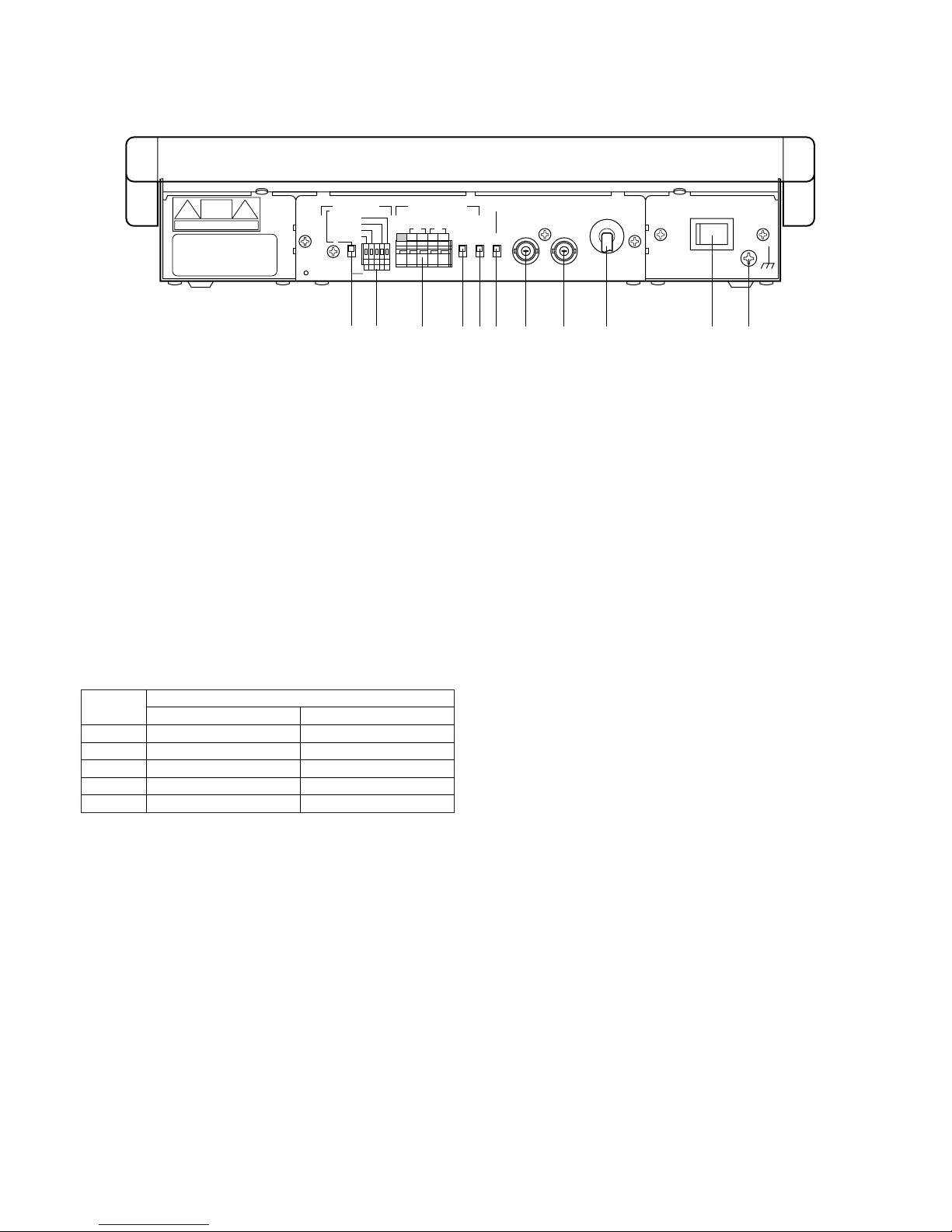
■ Rear View
POWER
OFF
SIGNAL GND
ON
CAMERA
IN
RS485ALARM DATA
TERM
VIDEO
OUT
RESET OUT
ALARM IN
RECOVER IN
ALARM OUT
ALARM IN
LINE
COAX
RS48542ONOFF
12G34
RT
ABABG
rty u i o !0 !1e
q w
q Alarm Switch
This switch is used to specify the functions for the 5-pin
terminal adjacent to the switch. When the switch is set
to the upper position, the terminals supply and accept
the alarm related signals with a Time Lapse VTR. When
the switch is in the lower position, the terminals accept
alarm inputs 1, 2, 3 and 4.
w Alarm Terminals
Terminal functions are specified by the alarm switch
position as shown in the table. Refer to page 13 for connection with a Time Lapse VTR.
e RS-485 Terminal
This terminal is used to exchange control data with the
camera site.
r Termination Switch (TERM ON/OFF)
This switch is used to terminate the RS-485 communication lines.
It should normally be kept in the ON position.
t Line Selection Switch (LINE 4/2)
This switch is used to select full-duplex (4-lines) or halfduplex (2-lines) for the communication lines.
y Data Selection Switch (DATA COAX/RS485)
This switch selects the data communication route from
among the multiplexing data on a coaxial cable or when
using an RS-485 line.
u Video Output Connector (VIDEO OUT)
This connector supplies composite video signals from
the camera.
i Camera Input Connector (CAMERA IN)
This connector accepts the multiplexed video and control data signals from the specified camera or a specified receiver.
o AC Cord
!0 Power Switch (POWER)
This switch is used to turn the System Controller power
on and off.
Caution: In the following cases, disconnect the AC
cord from the service outlet, or switch off an ALLPOLE MAIN SWITCH with a contact separation of at
least 3 mm in each pole incorporated in the electrical insulation of the building.
This is to be used when the controller needs to be
isolated from the AC mains, when the controller will
not be used for a long time, and when there is lightning.
!1 Signal Ground Terminal (SIGNAL GND)
Pin #
1
2
G
3
4
Switch Position
Up
Alarm Input
Alarm Output
Signal ground
Recover Input
Reset Output
Down
Alarm Input 1
Alarm Input 2
Signal ground
Alarm Input 3
Alarm Input 4
9
• Installation should be performed by qualified service personnel or system installers according to the following instructions.
• Disconnect the power cord from the service outlet before installation.
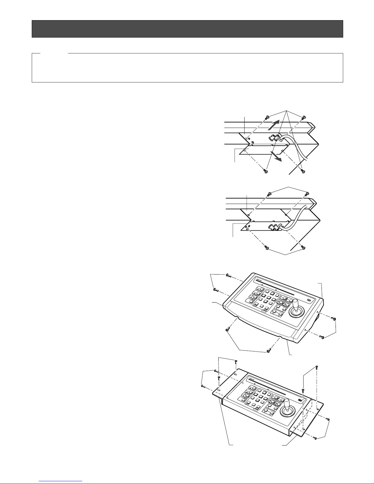
Installation
■ Mounting in the Rack
1. Remove the Connector Panel and Bottom Cover from
the controller by removing the four screws.
2. Mount the Connector Panel onto the bottom by using
the two screws that were removed above.
3. Mount the Bottom Cover onto the rear by using the two
screws that were removed above.
4. Remove the side panels by removing the four screws.
5. Remove the Palm Rest Panel by removing the two
screws.
6. Fix the Rack Mounting Angles onto both sides by using
the four screws.
7. Mount the controller in the EIA standard 19-inch rack.
Note: Always keep the temperature in the rack within 45 °C
{122 °F}.
Connector Panel
1
Bottom Cover
Bottom Cover
Connector Panel
3
2
S
y
s
t
e
m
C
o
n
t
r
o
l
l
e
r
W
V
-
C
U
5
4
1
2
0
6
3
9
8
7
S
y
s
t
e
m
C
o
n
t
r
o
ll
e
r
W
V
-
C
U
5
4
1
2
0
6
3
9
8
7
4
4
5
7 (Procured locally)
5 (Procured locally)
(Supplied:
WV-Q62)
6
6
(Supplied:
WV-Q62)
Rack Mounting Angle
(Optional Accessory: WV-Q62)
Palm Rest Panel
Side Panel
(Left)
Side Panel
(Right)
CAUTION
10
Connection & Setting
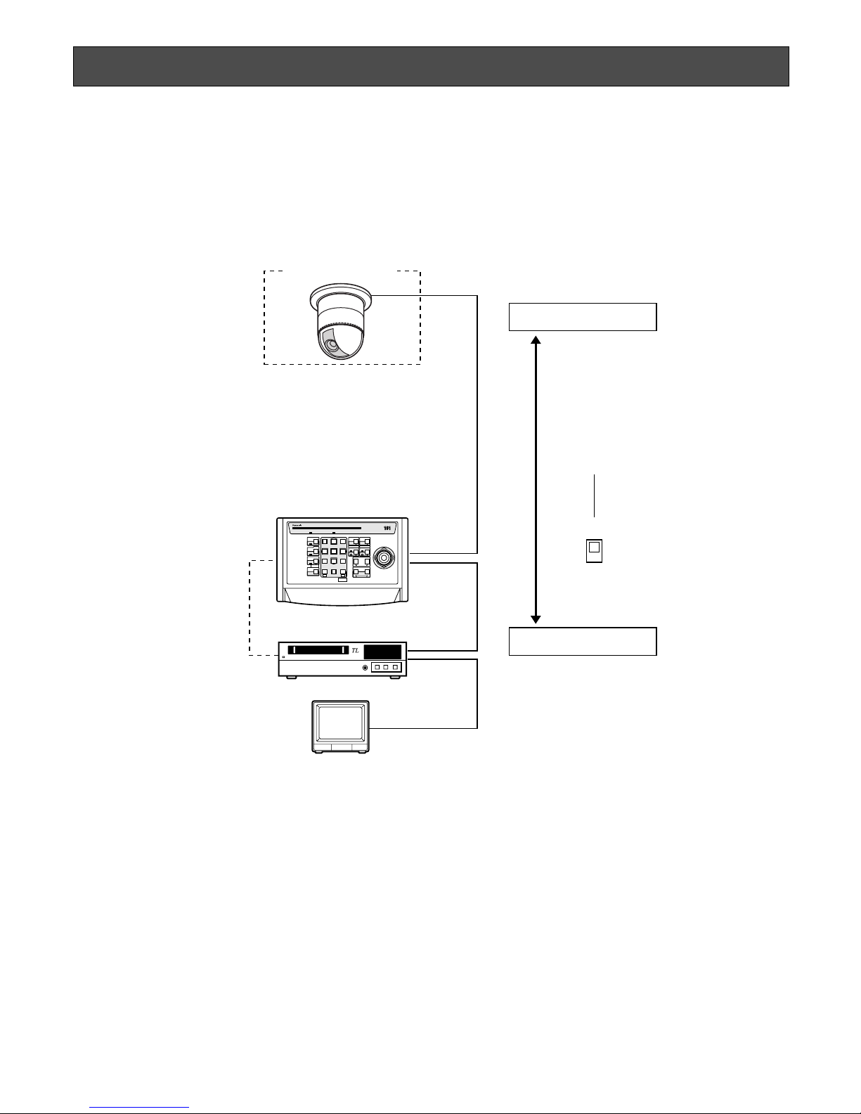
■ System Connection
● Basic Connection
The WV-CU161C can be connected with a camera, a Time Lapse VTR and a video monitor as in the typical system configuration shown below.
Combination Camera
WV-CU161C
Time Lapse VTR
System Controller WV-CU C
1 2 3
4 6
7 8 9
0
5
SHIFT
OPERATE ALARM
RESET
RESET
SUSPEND
CAMERA
SETUP
PATROL
PLAY
PROGRAM
PRESET
CAMERA
FUNCTION
SETUP
ESC
HOME
SET
PRESET
WIDE TELE
NEAR
AUX1
B/W
AUTO
WIPER
AUX2
DEF
UP
DOWN
RL
FAR
FOCUS
IRIS
CLOSS OPEN
PROGRAM
ALARM
IRIS RESET
AUTO FOCUS
Video Monitor
Camera Site
Control Site
ALARM INPUT/OUTPUT
(See page 13)
CAMERA
IN
VIDEO
OUT
VIDEO IN
VIDEO OUT
DATA
COAX
RS485
1 200 m or less
(with RG-6U or 5C-2V)
(Coaxial Multiplex
Communication)
Note: Refer to the operating instructions of each system component for connection and operation.
11
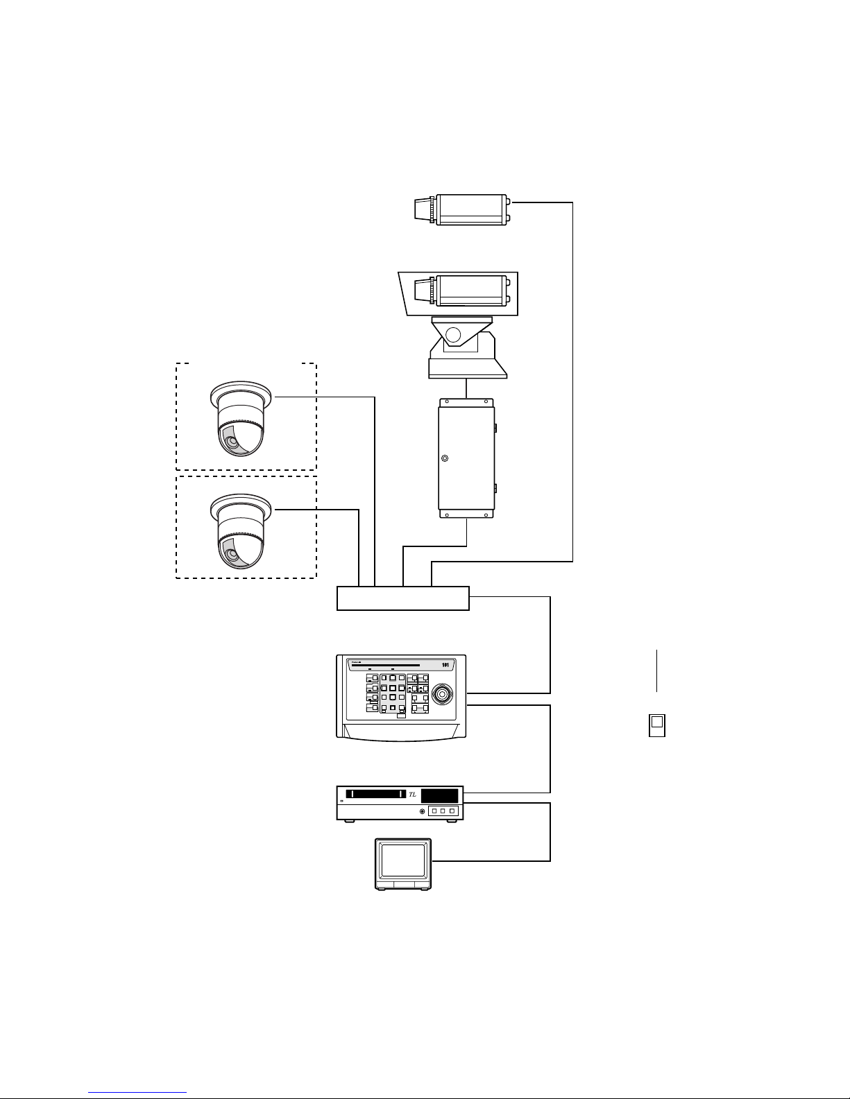
● Connecting more Cameras
A bi-directional video switcher purchased separately can be installed when connecting more than one camera. Video signal
reception, camera control and alarm input reception are only available between the camera selected and the controller due to
the nature of the switcher.
Combination Camera
Video Switcher
Camera Housing
Camera
Receiver
R
System Controller
WV-CU161C
System Controller WV-CU C
1 2 3
4 6
7 8 9
0
5
SHIFT
OPERATE ALARM
RESET
RESET
SUSPEND
CAMERA
SETUP
PATROL
PLAY
PROGRAM
PRESET
CAMERA
FUNCTION
SETUP
ESC
HOME
SET
PRESET
WIDE TELE
NEAR
AUX1
B/W
AUTO
WIPER
AUX2
DEF
UP
DOWN
L
FAR
FOCUS
IRIS
CLOSS OPEN
PROGRAM
ALARM
IRIS RESET
AUTO FOCUS
Video Monitor
Time Lapse VTR
DATA
COAX
RS485
CAMERA
IN
VIDEO
OUT
VIDEO IN
VIDEO OUT
Notes:
• When controlling a camera, wait for 5 seconds or more after camera selection. Camera control may not be available soon
after camera selection.
• Refer to the operating instructions of each system component for connection and operation.
12
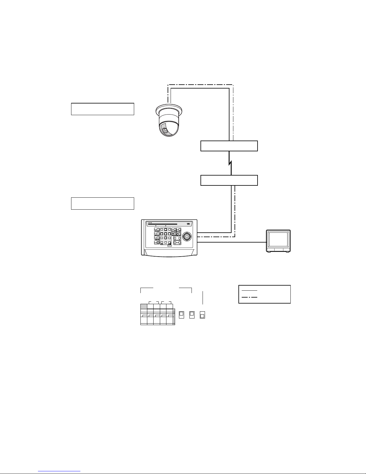
● Connecting with a Distant Camera Site
Using two Network Interface Units, that is a Transmitter and a Receiver, will help to extend the distance between the camera
and control sites. An RS-485 is used when the communication line is extended for more than 1 200 m {400 ft}.
WV-CS854A
Network Interface Unit
Network Interface Unit
R
System Controller
WV-CU161C
System Controller WV-CU C
1 2 3
4 6
7 8 9
0
5
SHIFT
OPERATE ALARM
RESET
RESET
SUSPEND
CAMERA
SETUP
PATROL
PAY
PROGRAM
PRESET
CAMERA
FUNCTION
SERUP
ESC
HOME
SET
PRESET
WIDE TELE
NEAR
AUX1
B/W
AUTO
WIPER
AUX2
DEF
UP
DOWN
L
FAR
FOCUS
IRIS
CLOSS OPEN
PROGRAM
ALARM
IRIS RESET
AUTO FOCUS
Video Monitor
DATA PORTTransmitter
Receiver
DATA PORTVIDEO OUT
CAMERA IN
VIDEO OUT
RS-485 Cable
Coaxial Cable
RS485 DATA
TERM LINE
COAX
RS485
4
2
ON
OFF
RT
ABABG
Public lines
Video signal
RS-485 signal
Camera Site
Control Site
Notes:
• Refer to the operating instructions for each system component for connecting and operating them.
• If the public line is busy, then it may cause instability for the system operation.
13
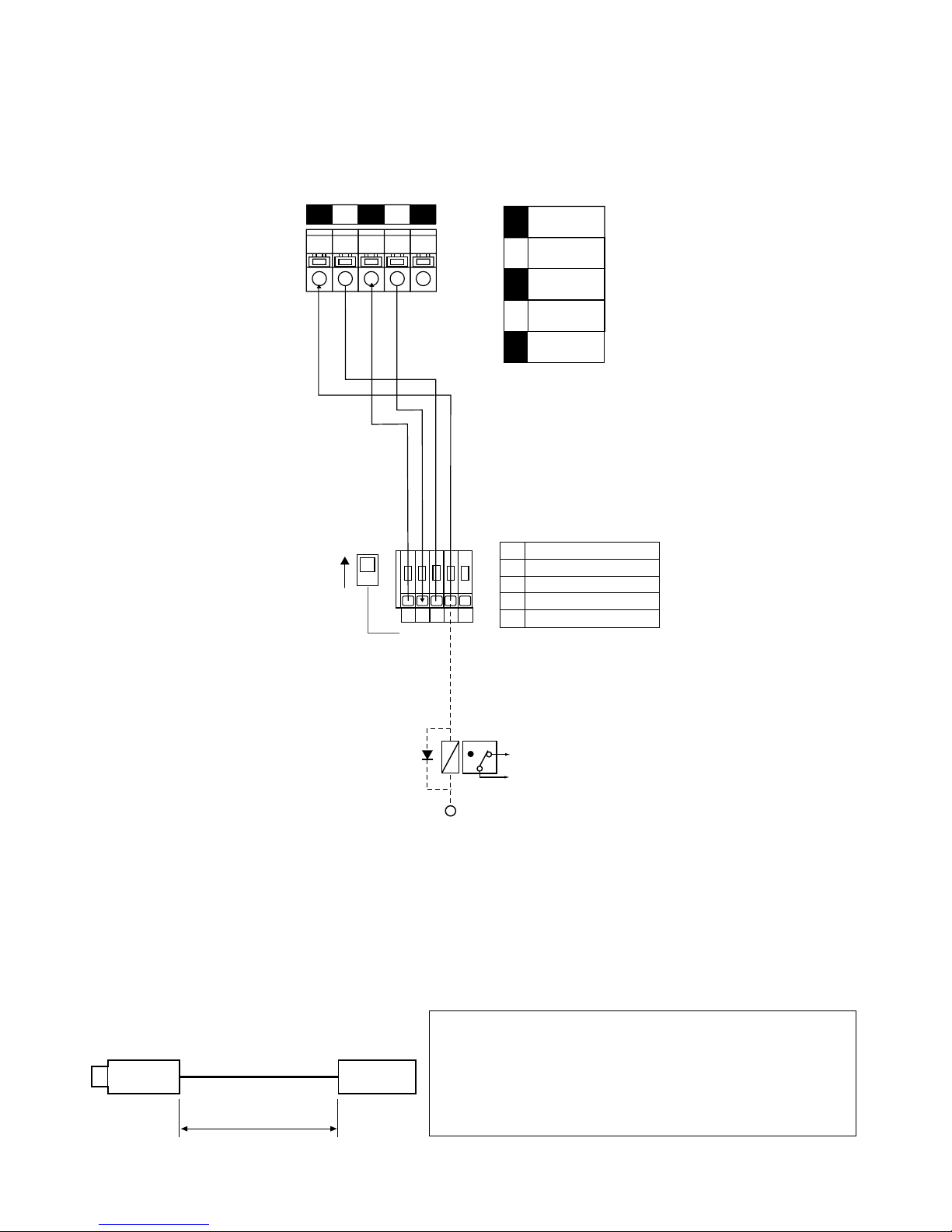
■ Connection with a Time Lapse VTR
Alarm in/out and recover-reset in/out are connected between the time lapse VTR and the rear of the controller.
Note: Use a relay as shown below when connecting an indicator such as a buzzer that exceeds 16 V DC 100 mA.
ALARM IN
1
2
G34
Relay
+12 V
NC
NO
Alarm Indicator etc.
Time Lapse VTR
1 ALARM IN
2 ALARM OUT
G GROUND
3 RECOVER IN
4 RESET OUT
NC: Normally Closed Contact
NO: Normally Open Contact
2 4
ALARM
IN
1
COM2
ALARM
RESET IN
3
ALARM
RECOVER OUT
4
ALARM
OUT
5
135
■ Cable-loss Compensation Setting
The maximum allowable cable length between a camera and a controller is 1 200 m {4 000 ft} when using an RG-6U or 5C-2V
or equivalent cable. Cable loss compensation can be adjusted in the setup menu as S, M or L.
Camera WV-CU161C
A m (A ft)
<Example>
0 {0} ≤ A < 500 {1 650} → S
500 {1 650} ≤ A < 900 {3 000} → M
900 {3 000} ≤ A < 1 200 {4 000}→ L
Cable compensation
parameter in WV-CU161C
Setup menu
Cable length (with RG-6U or 5C-2V)
Unit: m {ft}
14
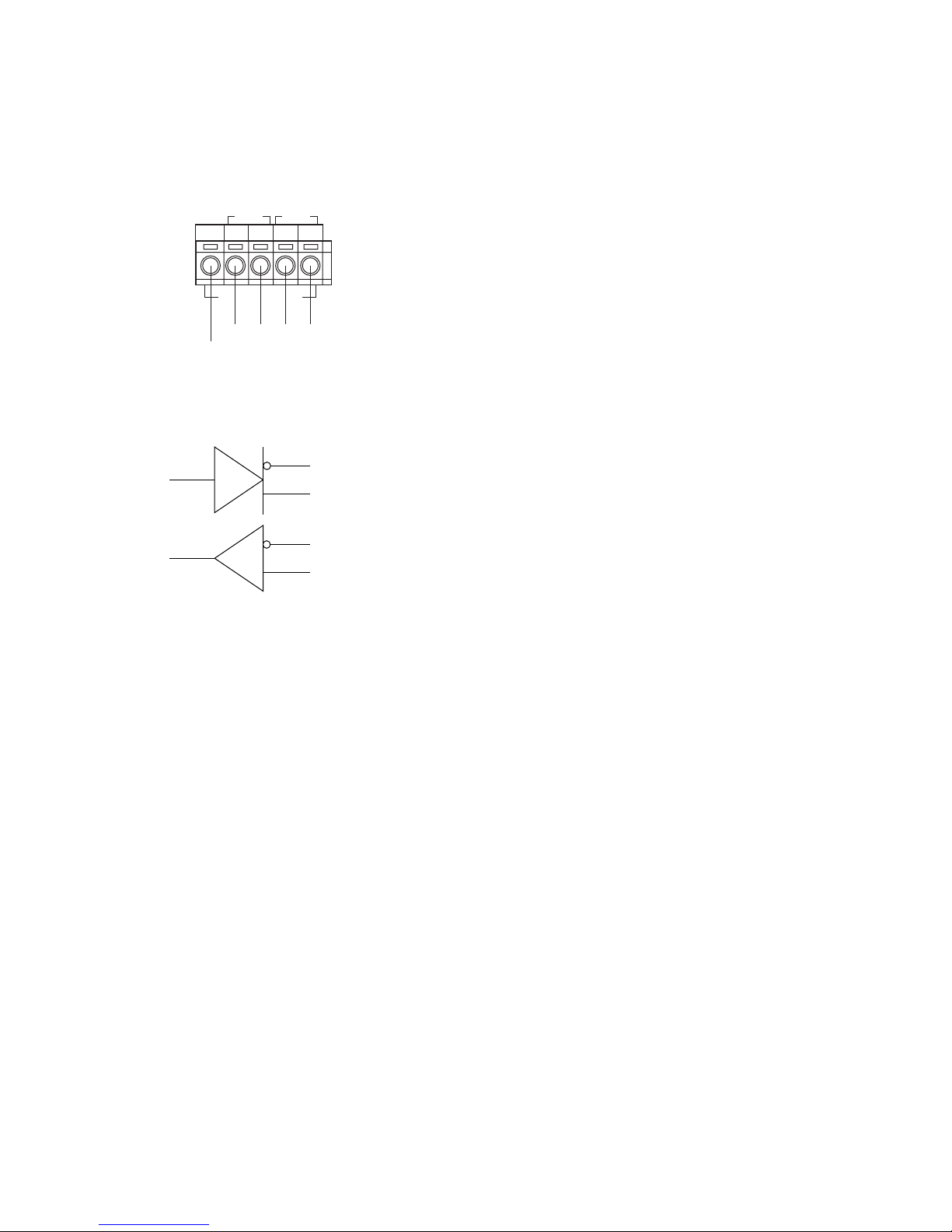
■ RS-485 Connection
Control data is transmitted and received between the controller and other peripherals. Use a shielded cable of data
communication grade, consisting of two twisted pairs suitable for RS485. Cable length may be extended up to
1 200 m {4 000 ft}.
● Internal Diagram
Note: Make sure to turn the DATA switch on the rear of the
controller to RS-485 position.
TR
RS485
ABABG
GND
5
TB TA RB RA
4321
RA
TB
4
3
2
1
TA
RB
15
■ Switch Setting
There are four switches on the rear of the controller for specifying the terminal definition and data communication conditions.
A signal form selection switch (SW1) and a character display mode switch (SW100) are mounted inside the controller. These
inner switches do not need to be adjusted when the controller is used with the factory default settings.
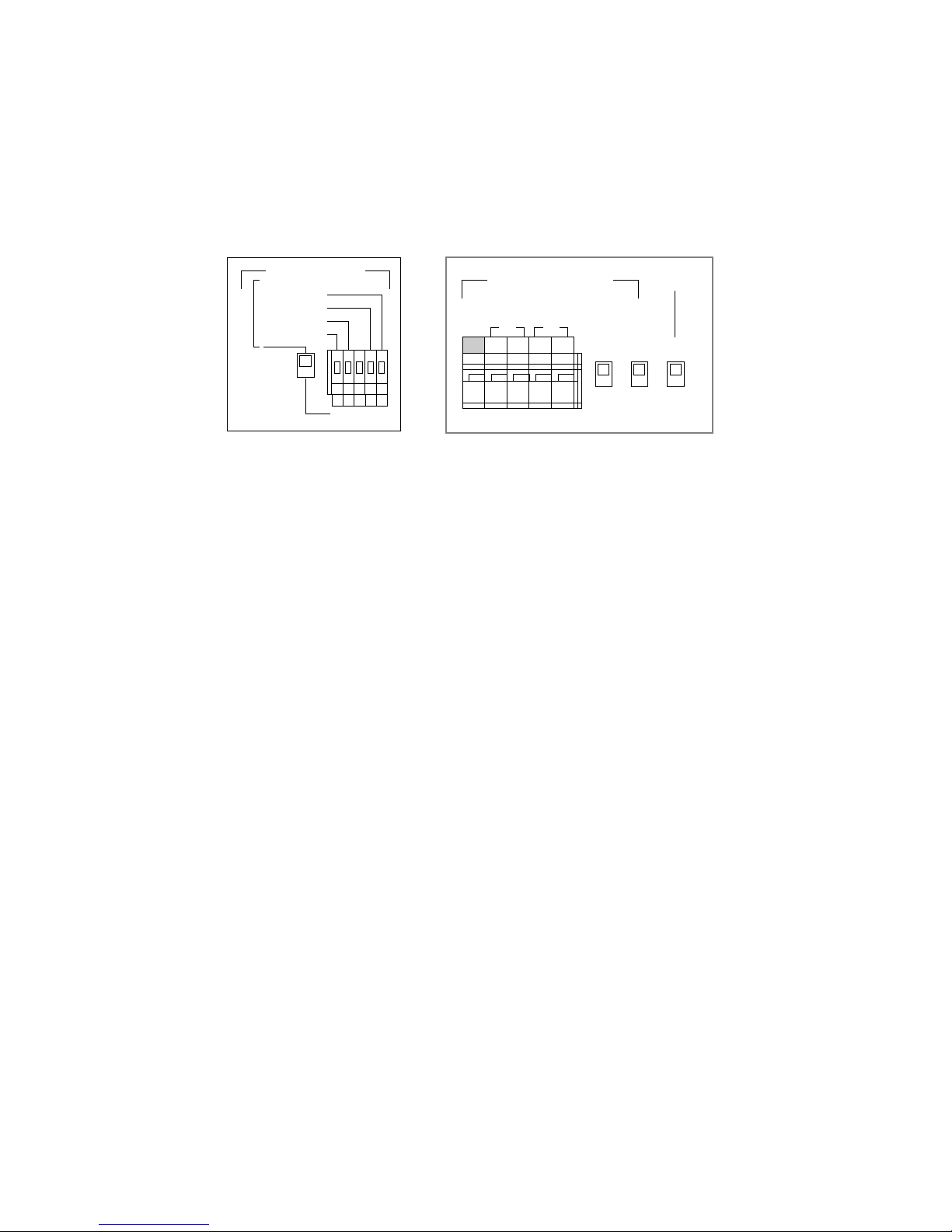
● Rear Panel Setting
Alarm Terminal Definition Switch
This switch specifies the functions for the 5-pin terminal. The default setting is the upper position.
Upper position: Used when connecting with a Time Lapse VTR. The terminals function as ALARM IN, ALARM OUT,
RECOVER IN and RESET OUT.
Lower position: Used when connecting with multiple alarm sensors. The terminals function as ALARM IN 1-4.
Termination Switch
This switch opens or terminates the RS-485 line. The default setting is ON.
ON: Used when connecting one to one. The line is terminated by a 150-ohm resister.
OFF: The line is open.
Line Switch
This switch specifies the RS-485 communication mode. Match it to the mode used by the connected devices. The default setting is 4.
4: 4-line full duplex
2: 2-line half duplex
Data Switch
This switch specifies the data communication route between the controller and the camera. The default setting is COAX.
COAX: Control commands and status information are transmitted and received through a coaxial cable.
RS485: Commands and status are transmitted and received through an RS-485 cable connected to the RS-485 terminal.
RS485 DATA
TERM LNE
COAX
RS485
4
2
ON
OFF
RT
ABABG
Rear Panel
ALARM
RESET OUT
ALARM IN
RECOVER IN
ALARM OUT
ALARM IN
12G34

16
Recover Output Switch (SW1)
1. Remove the bottom cover by removing the two screws.
The SW1 mounted inside the controller can be seen.
2. Set the SW1 to the desired position. The default setting
is 0/5V.
0/5V: 0 V or 5 V output, active when it is 5 V.
O.C: Open collector output, active when it is low.
Control capacity is 16 V 500 mA maximum.
3. Place the bottom cover as it was before and fasten the two screws.
Display mode Switch (SW100)
1. Remove the bottom cover as described above.
2. Remove the two side panels and the bottom panel by removing the twelve screws. The SW100 mounted inside the controller can be seen.
● Internal Switch Setting
Bottom
Cover
Panasonic
SW1
SW1
O.C 0/5V
SW100
Side Panel
Bottom Cover
Side Panel
• The internal switch setting should be performed by qualified service personnel or system installers.
• Unplug the controller power cord from the electric outlet before setting the internal switch in order to reduce the risk of
electric shocks.
Caution:
The internal switches, SW1 and SW100, can be readjusted to change the recover output signal form or character display mode
from the default settings.

17
3. Set the SW100 to the desired position. The default setting is NOR.
NOR: White letters are displayed with a black border.
REV: Black letters are displayed with a white border.
4. Place the side panels, bottom panel and bottom cover
in their previous positions and fasten the screws that
were previously removed.
SW100
NOR REV
18
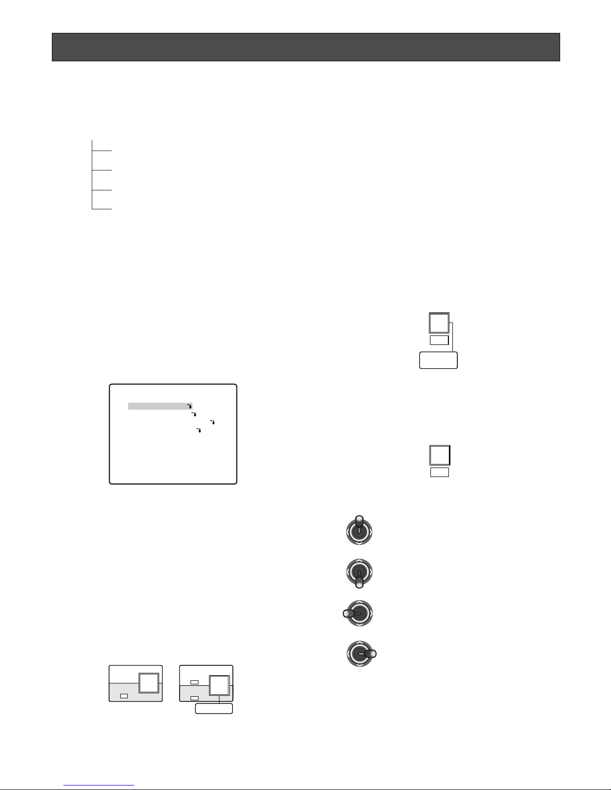
Setup Menu
The SETUP MENU has four main submenus: Alarm Setup, System Setup, Preset Data Load and Communication.
All of these main menus are further divided into submenus.
Alarm Setup (ALARM SETUP) ........................................................................................ Page 19
System Setup (SYSTEM SETUP) ................................................................................... Page 21
Preset Data Loading (PRESET DATA LOAD) .................................................................. Page 21
Communication Setup (COMMUNICATION) ................................................................... Page 24
Setup Menu (SETUP MENU)
■ Displaying the Setup Menu
1. Check that the camera, monitor and peripherals are
correctly and securely connected.
2. Switch all the system components on.
The operation indicator of the WV-CU161C lights up,
and the picture of the camera appears on the monitor.
3. Press the CAMERA SETUP/SETUP/PROGRAM button
for 2 seconds or more while the SHIFT indicator is lit.
4. The SETUP MENU appears.
Note: The COMMUNICATION parameter appears when the
DATA switch is set to RS-485 (See page 16).
■ Buttons & Controls used in the
Setup Menu
SHIFT button + CAMERA SETUP/SETUP/PROGRAM
button:
Press the CAMERA SETUP/SETUP/PROGRAM button
for 2 seconds or more while the SHIFT indicator is lit.
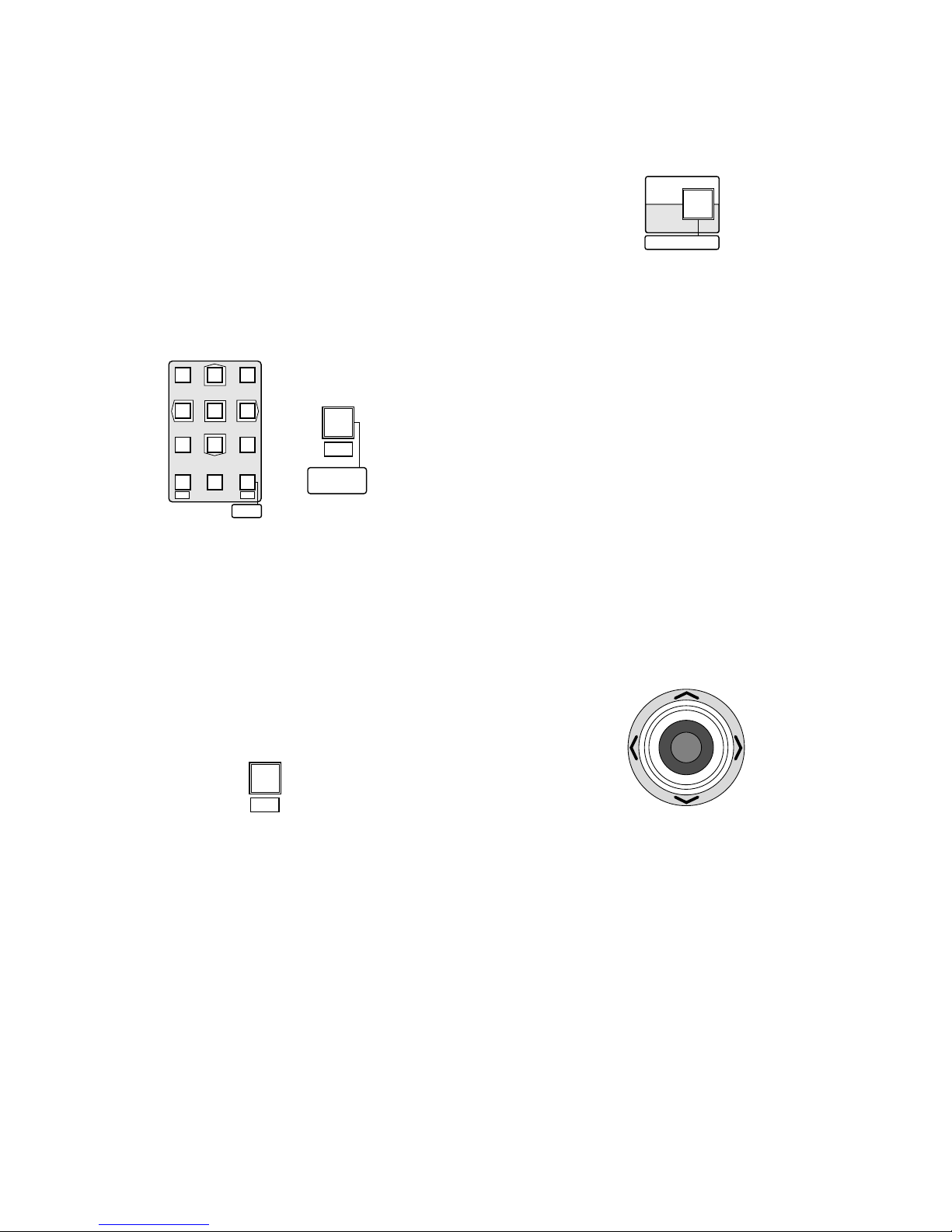
PRESET/SET/PROGRAM PRESET button:
Press this button to confirm the parameter selection or
to enter a submenu for an item marked with O.
HOME/ESC button:
Press this button to return to the previous menu.
WV-CU161C SETUP MENU *.**
ALARM SETUP
SYSTEM SETUP
PRESET DATA LOAD
COMMUNICATION
PROGRAM
PRESET
SET
PRESET
ESC
HOME
SHIFT
CAMERA
SETUP
SETUP
PROGRAM
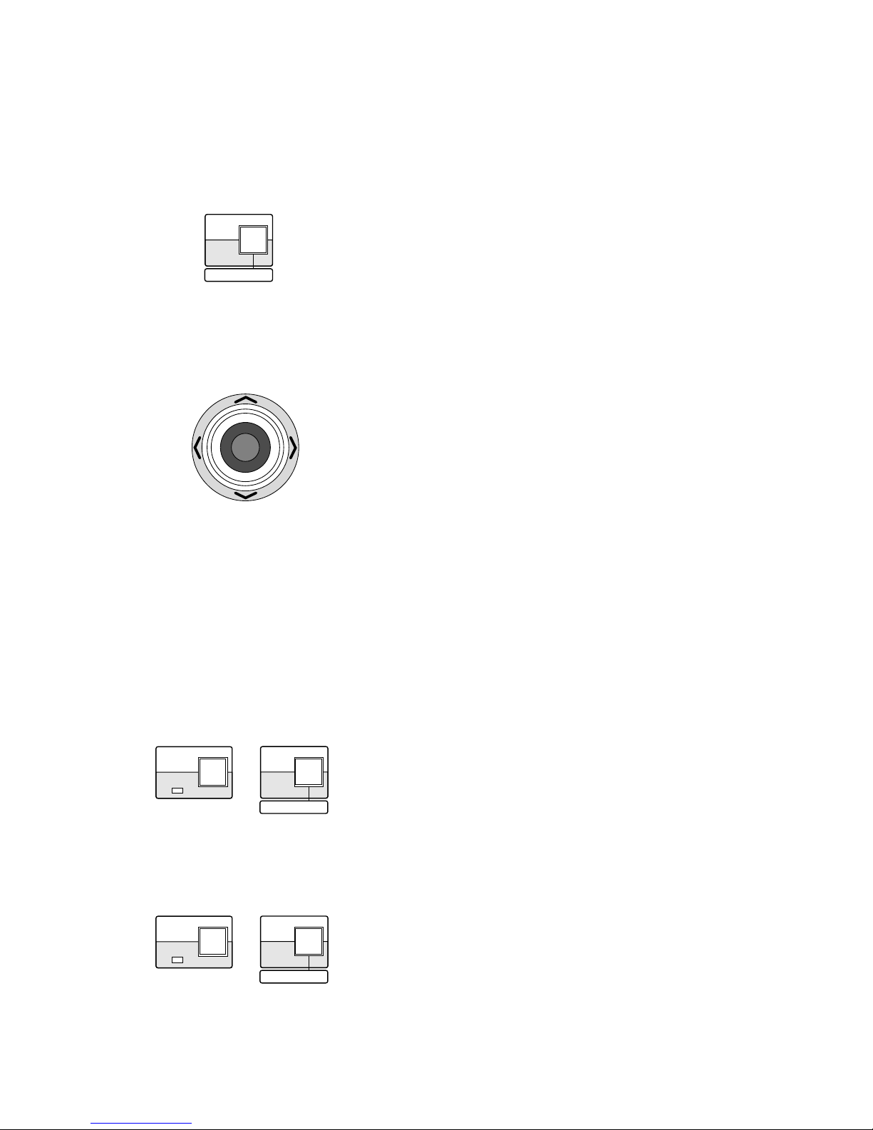
Up: To select a setup item.
Down: To select a setup item.
Left: To decrease the parameter.
Right: To increase the parameter.
DOWN
LR
UP
LR
UP
DOWN
R
UP
DOWN
LR
• Joystick Controller

19
• Closing Setup Menu
Press the PRESET/SET/PROGRAM PRESET button for 2
seconds or more while the SHIFT indicator is lit.
The SETUP indicator goes off.
Note: The new settings are not saved if the WV-
CU161C power is turned off before completing the
setup. Return to the WV-CU161C SETUP MENU,
complete the setup, and then turn the power off to
save the new settings.
■ Alarm Setup (ALARM SETUP)
Alarm related functions are set up.
1. Display the WV-CU161C SETUP MENU.
2. Move the cursor to ALARM SETUP O , and then press
the SET button.
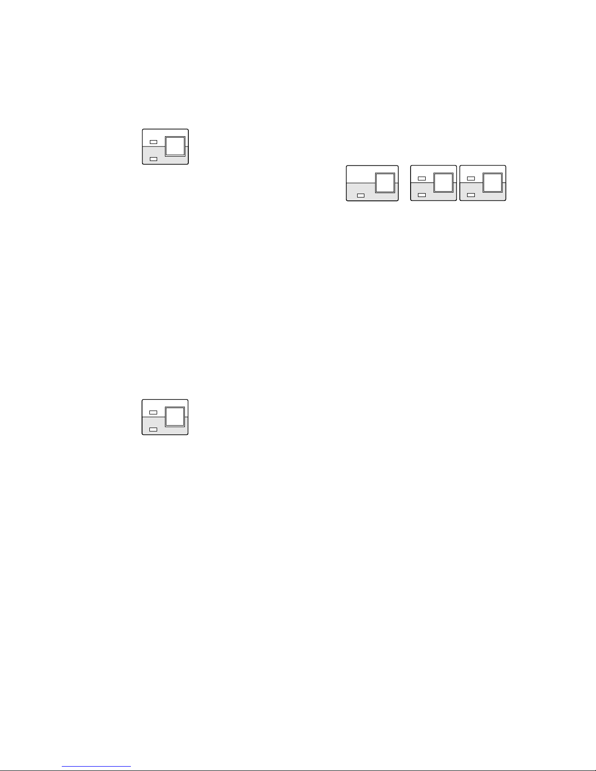
The setup menu appears depending on the ALARM
switch setting on the rear of the controller.
ALARM PRESET appears on the bottom of the menu
when the ALARM switch is set to the upper position to
connect with a time lapse VTR.
ALARM TERMINAL O appears on the bottom of the
menu when the ALARM switch is set to the lower position to connect with four sensors.
Alarm Display Setting (ALARM DISPLAY)
This item lets you select whether or not to display an
“ALARM” text line on the monitor when an alarm is activated.
1. Display the ALARM SETUP menu.
2. Move the cursor to ALARM DISPLAY.
3. Select ON or OFF using the joystick, and then press the
SET button. The factory setting is ON.
ON: Display is enabled.
OFF: Display is disabled.
Note: The display time differs depending on the Alarm
Output Setting.
Site Alarm Setting (SITE ALARM)
This item lets you enable or disable the controller to receive
the camera site alarm.
1. Display the ALARM SETUP menu.
2. Select SITE ALARM by moving the joystick up or down.
3. Select SITE ALARM ON or OFF by moving the joystick
to the right or left.
The initial factory setting is ON.
ON: The controller receives the site alarm (Video Motion
Detection: VMD) issued by the camera.
OFF: The site alarm is disabled.
Terminal Alarm Setting (TERM.ALARM)
This item lets you enable or disable the controller to receive
the alarm signal from the alarm connector.
1. Display the ALARM SETUP menu.
2. Select TERM.ALARM by moving the joystick up or
down.
3. Select TERM.ALARM ON or OFF by moving the joystick
to the right or left.
The initial factory setting is ON.
ON: Alarm activation through the terminal is received.
OFF: Alarm activation through the terminal is no
received.
Alarm Output Setting (ALARM OUTPUT)
This item lets you select the duration that the following three
functions continue working for after an alarm activation.
• The ALARM is displayed on the monitor (ALARM DISPLAY ON mode).
• The alarm is output to external devices (from the
ALARM OUTPUT connector).
• The buzzer sounds (ALARM BUZZER ON mode).
1. Display the ALARM SETUP menu.
2. Select ALARM OUTPUT by moving the joystick up or
down.
3. Select the desired alarm output duration of 1S-30S,
40S, 50S, 1MIN, 2MIN, 3MIN, 4MIN, 5MIN EXT or OFF
by moving the joystick to the right or left.
The initial factory setting is 10S.
EXT: The alarm signal continues to be output from the
alarm output connector until the alarm is reset. The
alarm is not automatically reset.
1S-5MIN: The alarm signal is only supplied from the
alarm output connector for the set time. The alarm is
automatically reset after the set time. The ALARM
indicator changes from blinking to a steady light.
OFF: No alarm output signal is supplied. (The alarm is
deactivated.)
ALARM SETUP
ALARM DISPLAY ON
SITE ALARM ON
TERM.ALARM ON
ALARM OUTPUT 10S
ALARM BUZZER ON
ALARM PRESET –
ALARM SETUP
ALARM DISPLAY ON
SITE ALARM ON
TERM.ALARM ON
ALARM OUTPUT 10S
ALARM BUZZER ON
ALARM TERMINAL

20
Alarm Buzzer Setting (ALARM BUZZER)
This item lets you select whether or not to sound the alarm
buzzer when an alarm is activated.
1. Display the ALARM SETUP menu.
2. Select ALARM BUZZER by moving the joystick up or
down.
3. Select ALARM BUZZER ON or OFF by moving the joystick to the right or left.
The initial factory setting is ON.
Note: The alarm buzzer time differs depending on (4) alarm
output setting.
Alarm Preset Position Setting
(ALARM PRESET)
This item lets you preset a camera position to an alarm
input. The camera will move its pan/tilt head to the position
when the alarm operates.
• The menu below appears when the ALARM switch on
the rear of the controller is set to the upper position to
connect with a Time Lapse VTR.
1. Display the ALARM SETUP menu.
2. Select ALARM PRESET by moving the joystick up or
down.
3. Move the joystick to the right or left to select the
desired preset numbers of the picture on the monitor in the range from 1-64 or [–] if no preset numbers are assigned.
The initial factory setting is – (No assignment).
1-64: Preset numbers
–: No assignment
Note: ALARM PRESET is only available when a
combination camera is connected.
Alarm Terminal (ALARM TERMINAL)
The menu below appears when the ALARM switch on the
rear of the controller is set to the lower position to receive
the four sensor inputs.
1. Display the ALARM SETUP menu.
2. Select ALARM TERMINAL by moving the joystick up or
down.
3. Press the PRESET/SET/PROGRAM PRESET button.
The ALARM TERMINAL menu opens.
4. Select the alarm terminal number by moving the joystick
up or down.
5. Move the joystick to the right or left to select the desired
preset numbers.
The initial factory setting is – (No assignment).
1-64: Preset numbers
–: No assignment
6. Press the HOME/ESC button to return to the previous
menu.
Notes:
• ALARM TERMINAL is only available when a combination camera is connected.
• If the camera has the Preset Alarm ON/OFF mode, then
set it to OFF.
ALARM SETUP
ALARM DISPLAY ON
SITE ALARM ON
TERM.ALARM ON
ALARM OUTPUT 10S
ALARM BUZZER ON
ALARM PRESET –
ALARM SETUP
ALARM DISPLAY ON
SITE ALARM ON
TERM.ALARM ON
ALARM OUTPUT 10S
ALARM BUZZER ON
ALARM TERMINAL
ALARM TERMINAL
ALARM PRESET
1 2 3 4 -
21
■ System Setup (System Setup)
1. Display the WV-CU161C SETUP MENU.
2. Select SYSTEM SETUP by moving the joystick up or
down.
3. Press the PRESET/SET/PROGRAM PRESET button.
The SYSTEM SETUP menu appears on the monitor.
Cable Compensation Setting (CABLE COMP)
This item lets you select a compensation level to match to
transmission loss caused by cable extension.
1. Display the SYSTEM SETUP menu.
2. Select CABLE COMP by moving the joystick up or
down.
3. Select the most appropriate cable length by moving the
joystick to the right or left.
The initial factory setting is S.
S: Less than 500 m {1 650 ft}
M: 500 m {1 650 ft} to 900 m {3 000 ft}
L: 900 m {3 000 ft} to 1 200 m {4 000 ft}
(with RG-6U or 5C-2V)
Switch Buzzer Setting (SWITCH BUZZER)
This item lets you select whether or not to sound the switch
buzzer when a button is pressed.
1. Display the SYSTEM SETUP menu.
2. Select SWITCH BUZZER by moving the joystick up or
down.
3. Select the ON or OFF mode by moving the joystick to
the right or left.
The initial factory setting is ON.
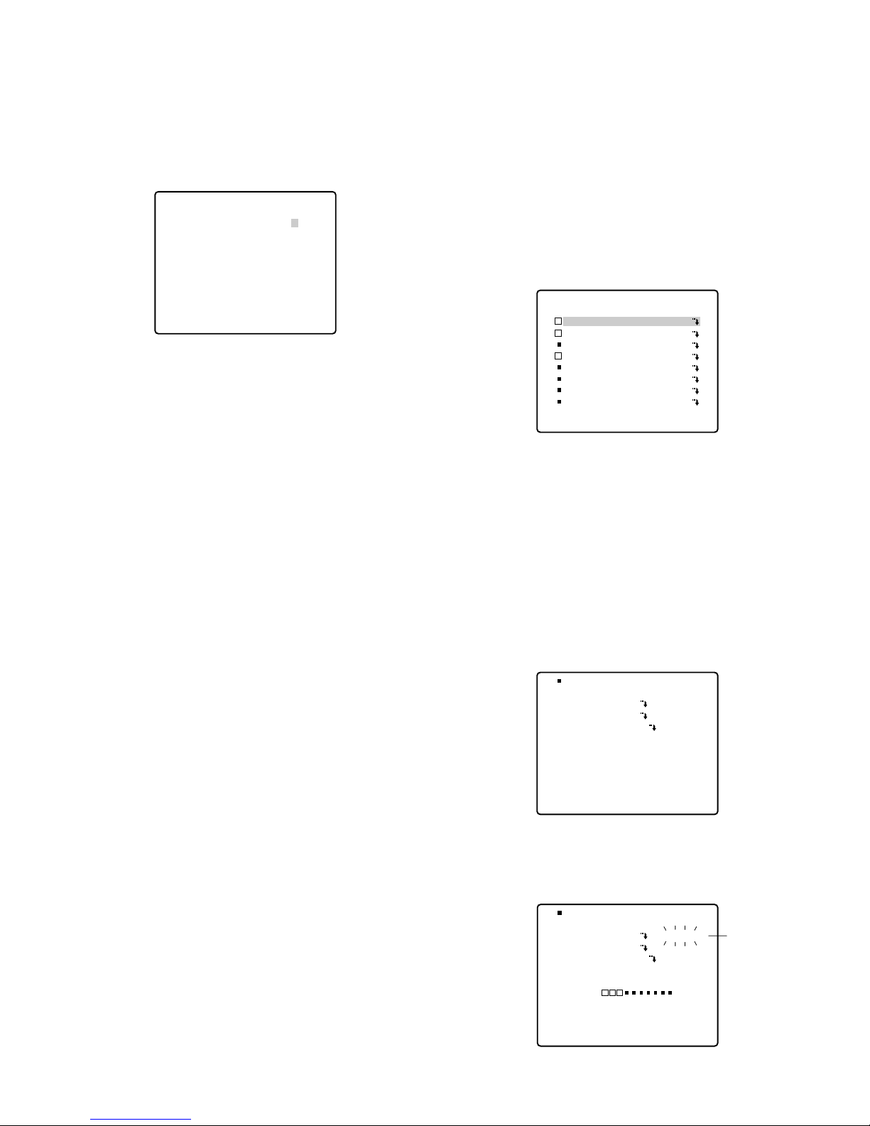
■ Preset Data Loading
(PRESET DATA LOAD)
The data settings preset to the camera are downloaded to
the controller. A set of preset data can be given a title by
the controller operation. The preset data with the title can
be uploaded to other cameras.
1. Display the WV-CU161C SETUP MENU.
2. Select PRESET DATA LOAD O by moving the joystick
up or down.
3. Press the PRESET/SET/PROGRAM PRESET button.
The PRESET DATA LOAD screen appears on the monitor as shown below.
P : Data saved.
■ : No Data saved. (The factory default setting for all
cameras from CAM1 to CAM8 is
■.)
Downloading (DOWN LOAD)
1. Display the PRESET DATA LOAD menu.
2. Select a camera number between CAM1 and CAM8 by
moving the joystick up or down.
3. Press the PRESET/SET/PROGRAM PRESET button.
The camera number and download menu appear on
the monitor as shown below.
4. Select DOWN LOAD by moving the joystick up or down.
5. Press the PRESET/SET/PROGRAM PRESET button.
Downloading starts.
SYSTEM SETUP
CABLE COMP S
SWITCH BUZZER ON
PRESET DATA LOAD
CAM1:
CAM2:
CAM3:
CAM4:
CAM5:
CAM6:
CAM7:
CAM8:
CAM1:
DOWN LOAD
UP LOAD
DATA TITLE
CAM1:
DOWN LOAD
UP LOAD
DATA TITLE
END
LOADING Blinking
22
6. The text line LOADING blinks on the right while downloading.
The bar graph changing from
■ to
P
displays the down-
loading progress.
7. END appears on the right after downloading has been
completed. The progress bar disappears.
8. Editing the DATA TITLE.
For further information, refer to Data Title on the next
page.
Notes:
• Preset data for up to 8 cameras can be downloaded.
• Downloading time is approximately 2 minutes per camera.
• Any previously preset data is overwritten by the downloaded data.
• Press the HOME/ESC button while downloading to terminate downloading. ERROR 3 appears. The progress
bar disappears.
• END and error messages remain on the menu until the
next operation is performed.
• Check that the right unit address is selected for the
combination camera when the RS-485 mode is used. If
the numbers do not agree, the camera cannot be operated.
Therefore, preset data cannot be downloaded.
• Error Display
The following messages appear on the monitor when an
error occurs during downloading.
ERROR 2
Message Cause Note
Lack of memory
Memory capacity was
exceeded while downloading.
ERROR 3 Causes except
above
Downloading not possible for some reason
other than the above.
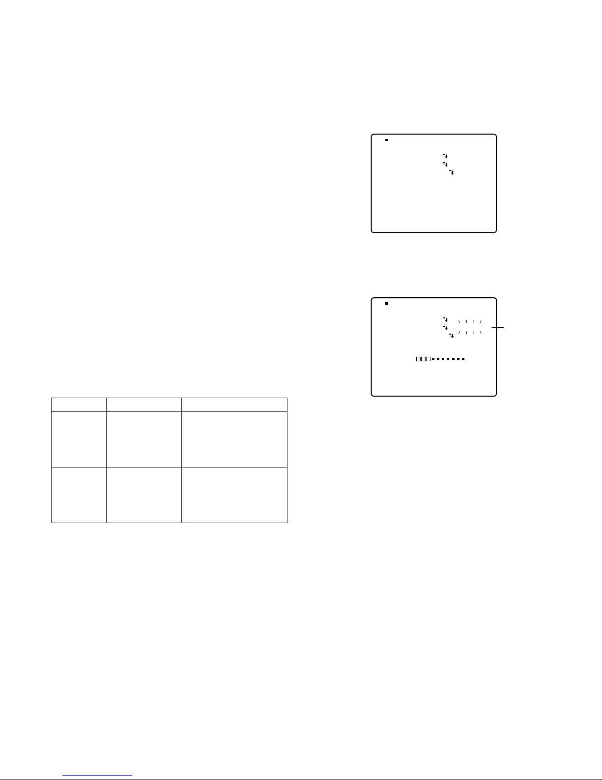
Uploading (UP LOAD)
1. Display the PRESET DATA LOAD menu.
2. Select a camera number between CAM1 and CAM8 by
moving the joystick up or down.
3. Press the PRESET/SET/PROGRAM PRESET button.
The camera number and upload menu appear on the
monitor as shown below.
4. Select UP LOAD by moving the joystick up or down.
5. Press the PRESET/SET/PROGRAM PRESET button.
Uploading starts.
6. The text line LOADING appears on the right while
uploading.
The bar graph changing from
■ to
P
displays the
uploading progress.
7. END appears on the right after the uploading has been
completed. The progress bar disappears.
Notes:
• Preset data for up to 8 cameras can be uploaded.
• The uploading time is approximately 2 minutes per
camera. When uploading is completed, combination
cameras such as the WV-CS854 will move during the
initial periods to fit the new settings.
• The camera picture may change as a result of
uploaded data. Access the Camera Setup menu to
make any necessary settings.
• Any previous preset data is overwritten by the uploaded
data.
• Press the HOME/ESC button to terminate uploading.
ERROR 3 appears and the progress bar disappears.
• END and error messages remain on the menu until the
next operation is performed.
CAM1:
DOWN LOAD
UP LOAD
DATA TITLE
END
LOADING Blinking
CAM1:
DOWN LOAD
UP LOAD
DATA TITLE
23
• Check that the right unit address is selected for the
combination camera when using the RS-485 mode. The
camera cannot be operated if the numbers do not
agree.
Therefore, preset data cannot be uploaded.
• Error Display
The following messages appear on the monitor when
errors occur during uploading.
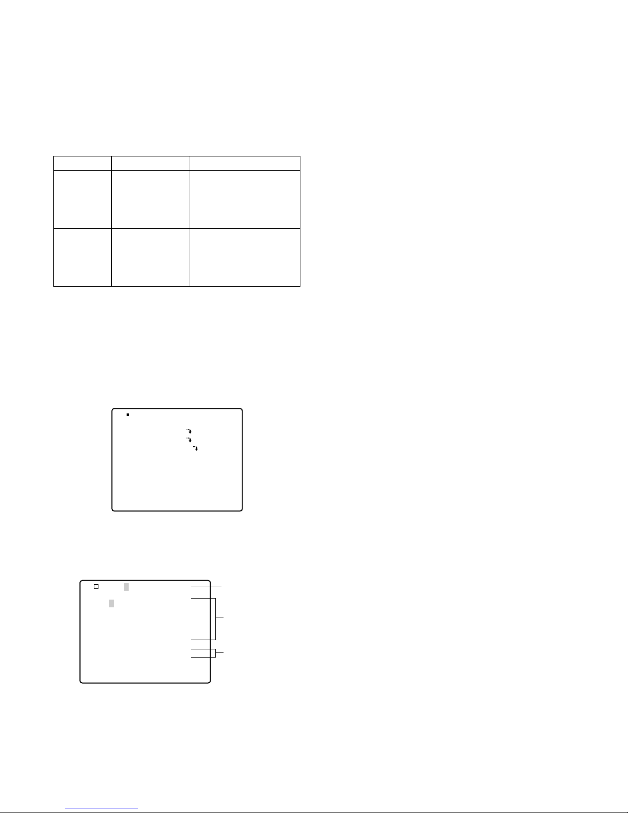
Data Title (DATA TITLE)
1. Display the PRESET DATA LOAD menu.
2. Select the desired CAM1-CAM8 position by moving the
joystick up or down.
3. Press the PRESET/SET/PROGRAM PRESET button.
The camera number and data title menu appear on the
monitor as shown below.
4. Select DATA TITLE by moving the joystick up or down.
Press the PRESET/SET/PROGRAM PRESET button.
The menu shown below appears on the monitor.
5. Move the cursor to the desired character symbol in the
character symbol area by moving the joystick up, down,
right or left, and then pressing the PRESET/SET/PROGRAM PRESET button. The selected character is displayed in the title area.
Message
6. Repeat step 5 to complete the data title. A title of up to
12 characters can be selected.
7. After setting all data titles, press the HOME/ESC button
to return to the Preset Data Menu.
To replace a specific character
1. Move the cursor to the title area by moving the joystick.
2. Move the cursor on the character to be replaced by
moving the joystick right or left.
3. Move the cursor from there to the desired character in
the character area by moving the joystick up or down,
and move the cursor to the desired character by moving the joystick up, down, right or left.
4. Press PRESET/SET/PROGRAM PRESET button.
The character selected in the title area is replaced with
the correct character.
To delete a specific character
A specific character can be deleted by selecting "SPACE"
to replace it in the character area.
1. Move the cursor to the title area by moving the joystick.
2. Move the cursor on the character to be deleted by moving the joystick right or left.
3. Move the cursor from there to "SPACE" in the character
area by moving the joystick up or down.
4. Press the PRESET/SET/PROGRAM PRESET button.
The character selected in the title area is deleted.
[•] (space mark) appears in place of the deleted character.
ERROR1
Cause Note
Incompatibility
Incompatibility detected
between transmission
data and camera model
while uploading.
ERROR 3 Causes except
above
Uploading not possible
for some reason other
than the above.
CAM1:
DOWN LOAD
UP LOAD
DATA TITLE
CAM1:
0123456789
ABCDEFGHIJKLM
NOPQRSTUVWXYZ
().,’”:;&#!?=
+-*/%$ДЬЦЖСЕ
SPACE
Title Area
Character Area
Space

24
Parity Check (PARITY CHECK)
This item lets you set the parity check mode for RS-485
communication.
1. Display the COMMUNICATION menu.
2. Select PARITY CHECK by moving the joystick up or
down.
3. Select NONE, EVEN or ODD for the parity check by
moving the joystick to the right or left.
The initial factory setting is NONE.
Note: This setting must be compatible with the peripherals
connected.
Stop Bit (STOP BIT)
This item lets you set the number of stop bits for RS-485
communication.
1. Display the COMMUNICATION menu.
2. Select STOP BIT by moving the joystick up or down.
3. Select 1 or 2 for the number of stop bits by moving the
joystick to the right or left.
The initial factory setting is 1 bit.
Note: This setting must be compatible with the peripherals
connected.
Wait Time (WAIT TIME)
This item lets you set the waiting time in milliseconds (ms)
until the next RS-485 communication retry.
1. Display the COMMUNICATION menu.
2. Select WAIT TIME by moving the joystick up or down.
3. Select OFF, 100, 200, 400 or 1000 ms for the wait time
by moving the joystick to the right or left.
The initial factory setting is OFF (No retry).
Delay Time (DELAY TIME)
This item lets you set the minimum delay time from the
reception of data to the reply for RS-485 communication.
1. Display the COMMUNICATION menu.
2. Select DELAY TIME by moving the joystick up or down.
3. Select OFF, 20, 40 or 100 ms for the delay time by moving the joystick to the right or left.
The initial factory setting is OFF.
XON/XOFF
This item lets you set the flow control for RS-485 communication.
1. Display the COMMUNICATION menu.
2. Select XON/OFF by moving the joystick up or down.
3. Select the NOT USE or USE mode by moving the joystick to the right or left.
The initial factory setting is NOT USE.
■ Communication Setup
(COMMUNICATION)
Note: The COMMUNICATION menu appears when the
DATA switch is set to RS-485.
Unit Address (UNIT ADDRESS)
This item lets you set the unit address assigned to the camera for RS-485 communication. Be sure to confirm the camera unit address before setting up this item.
1. Display the COMMUNICATION menu.
2. Select UNIT ADDRESS by moving the joystick up or
down.
3. Select the unit address assigned to the combination
camera in the range from 1 to 96 by moving the joystick
to the right or left.
The initial factory setting is 1.
Note: The camera cannot be operated if an address differ-
ent from that set on the camera is selected.
Baud Rate (BAUD RATE)
This item lets you set the baud rate for RS-485 communication.
1. Display the COMMUNICATION menu.
2. Select BAUD RATE by moving the joystick up or down.
3. Select 19200, 9600, 4800 or 2400 bps for the baud rate
by moving the joystick to the right or left.
The initial factory setting is 19200 bps.
Notes:
• The data response may be unstable at the baud rate of
2400 bps for some functions such as resetting alarms.
• This setting must be compatible with the peripherals
connected.
Data Bit (DATA BIT)
This item lets you set the number of data bits for RS-485
communication.
1. Display the COMMUNICATION menu.
2. Select DATA BIT by moving the joystick up or down.
3. Select 7 or 8 bits for the number of data bits by moving
the joystick to the right or left.
The initial factory setting is 8 bits.
Note: This setting must be compatible with the peripherals
connected.
COMMUNICATION
UNIT ADDRESS 1
BAUD RATE 19200
DATA BIT 8
PARITY CHECK NONE
STOP BIT 1
WAIT TIME OFF
DELAY TIME OFF
XON/XOFF NOT USE
25
CAMERA CONTROL FUNCTIONS
Camera control functions are operable.
It is necessary to set up the camera before using the camera control functions. For further information, refer to the
Operating Instructions for the respective combination camera (See page 33). You can also set it up from the Camera
Setup menu during operating the system.
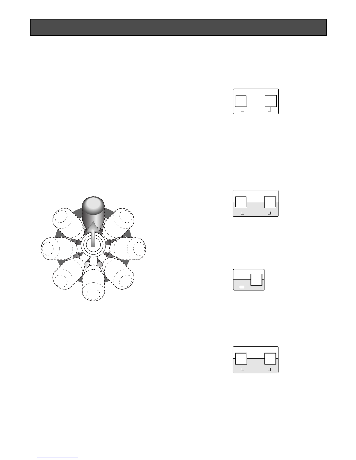
■ Pan/Tilt Control
A combination camera or an ordinary camera with pan/tilt
head can be controlled.
Move the pan/tilt head in the desired direction using the
joystick.
To move the pan/tilt head slowly, move the joystick while
holding down the SLOW/CAMERA FUNCTION button.
Note: The SLOW/CAMERA FUNCTION button only works in
combination with cameras or pan/tilt heads that are provided with more than 8-step speeds.
Operating Procedures
■ Lens Control
A motorized lens can be controlled.
1. Press the FOCUS NEAR or FOCUS FAR button to
adjust the lens focus while watching the monitor.
If you are using a camera with an auto focus feature,
then the lens focus can be automatically adjusted by
simultaneously pressing the FOCUS NEAR and
FOCUS FAR buttons.
2. Press the ZOOM TELE button to zoom in on the object
or press the ZOOM WIDE button to zoom out from the
scene.
The focal length differs depending on the lens installed
on the camera.
3. Press the SHIFT button.
4. Press the ZOOM/IRIS buttons to adjust the lens iris
while watching the monitor.
If the IRIS CLOSE and IRIS OPEN buttons are simulta-
neously pressed for approximately 1 second or more,
then the iris is reset to the default values.
NEAR FAR
FOCUS
AUTO FOCUS
WIDE TELE
IRIS
ZOOM
CLOSE OPEN
IRIS RESET
SHIFT
WIDE TELE
IRIS
ZOOM
CLOSE OPEN
IRIS RESET
Joystick
26
● Auto Pan
The combination camera starts a specific panning mode
preset beforehand.
1. Press the AUTO/B/W/PATROL STOP button.
The auto panning function is activated.
The picture appears on the monitor.
The following functions may be also available depending on the combination camera.
AUTO PAN ON or functions set in the combination
camera:
Press the numeric button 1 and then press this
button.
AUTO SORT ON: Press the numeric button 2 and then
press this button.
AUTO SEQ ON: Press the numeric button 3 and then
press this button.
RANDOM PAN ON: Press the numeric button 4 and
then press this button.
For further information, refer to the Operating Instructions for the combination camera.
2. To stop auto pan, move the joystick.
■ Operation of Combination Camera
It is necessary to set up the combination camera before
operating it. For further setup information, refer to the
Operating Instructions for the combination camera (See
page 30). You can also set it up from the Camera Setup
menu during operating the system.
● Moving to a Preset Position
The combination camera is moved to a position preset
beforehand.
Select a preset number using the numeric buttons, and
then press the PRESET/SET/PROGRAM PRESET button.
The picture of the camera in that position appears on the
monitor.
● Moving to the Home Position
The combination camera is moved to the home position
preset beforehand.
Press the HOME/ESC button.
The picture in that position appears on the monitor.
1 2 3
4 6
7 8 9
0
5
PROGRAM
PRESET
ESC
HOME
SET
PRESET
PROGRAM
PRESET
SET
PRESET
ESC
HOME
B/W
AUTO
PATROL STOP
UP
LR
DOWN
27
● Patrol Play
The combination camera reproduces a series of pan/tilt
movements and lens controls that have been preset beforehand in Patrol Learning.
See page 33 to program the camera patrol learning function.
1. Press the PATROL PLAY/PATROL LEARN button.
The camera patrol picture appears on the monitor.
2. To stop the patrol play function, move the joystick.
● Colour or Black & White
A black and white image is easier to view in dark places
while a coloured image is better to use in the daylight.
Changing from colour to B/W and B/W to colour can be
done manually.
1. Press the AUTO/B/W/PATROL STOP button, while the
SHIFT indicator is lit, to change from colour to a black
and white picture. The black and white picture appears
on the monitor.
2. Press the AUTO/B/W/PATROL STOP button while the
SHIFT indicator is lit to change back from black and
white to a colour picture.
Note: This function is disabled when the B/W is set to
AUTO in the camera setup. Set the B/W to ON or OFF to
make manual operations possible.
PATROL
PLAY
PATROL LEARN
UP
LR
DOWN
B/W
AUTO
PATROL STOP
SHIFT
B/W
AUTO
PATROL STOP
SHIFT

28
● Combination Camera Shortcuts
The combination camera is controlled using the hundred shortcuts shown in the table. While the SHIFT indicator is lit, type a
number using the numeric buttons, and then press the CAMERA FUNCTION button. [CAM FUNC] in the table below is an
abbreviation for the CAMERA FUNCTION button. For more details, refer to the Operating Instructions included with the camera.
Selecting a PRESET position From #1 to #64
#1 [1] + [CAM FUNC]
#10 [1] + [0] + [CAM FUNC]
#64 [6] + [4] + [CAM FUNC]
AUTO PAN
ON [6] + [5] + [CAM FUNC]
OFF [6] + [6] + [CAM FUNC]
Speed Up [6] + [7] + [CAM FUNC]
Speed Down [6] + [8] + [CAM FUNC]
Setting Start Point [6] + [9] + [CAM FUNC]
Setting End Point [7] + [0] + [CAM FUNC]
Setting PAN Reverse [7] + [4] + [CAM FUNC]
AUTO MODE
MODE Off [7] + [1] + [CAM FUNC]
SEQ On [7] + [2] + [CAM FUNC]
SORT On [7] + [3] + [CAM FUNC]
ENDLESS PAN
On [7] + [6] + [CAM FUNC]
Off [7] + [7] + [CAM FUNC]
DIGITAL FLIP
On [7] + [8] + [CAM FUNC]
Off [7] + [9] + [CAM FUNC]
PROP. PAN/TILT
On [8] + [0] + [CAM FUNC]
Off [8] + [1] + [CAM FUNC]
SUPER-D2
On [8] + [4] + [CAM FUNC]
Off [8] + [5] + [CAM FUNC]
AUTO FOCUS
STOP AF On* [8] + [6] + [CAM FUNC]
STOP AF Off* [8] + [7] + [CAM FUNC]
AF On (Activate) [8] + [8] + [CAM FUNC]
HOME POSITION
Move to HOME [8] + [9] + [CAM FUNC]
B/W or C/L
B/W On* [9] + [0] + [CAM FUNC]
B/W Off* [9] + [1] + [CAM FUNC]
B/W AUTO* [9] + [2] + [CAM FUNC]
CAMERA ID
On [9] + [3] + [CAM FUNC]
Off [9] + [4] + [CAM FUNC]
AREA TITLE
NESW On [9] + [5] + [CAM FUNC]
USER On [9] + [6] + [CAM FUNC]
TITLE Off [9] + [7] + [CAM FUNC]
EL-ZOOM
On [9] + [8] + [CAM FUNC]
Off [9] + [9] + [CAM FUNC]
RESTART
Begin [1] + [0] + [0] + [CAM FUNC]
Memorize PRESET From #1 to #64**
Position #1 [1] + [0] + [1] + [CAM FUNC]
Position #10 [1] + [1] + [0] + [CAM FUNC]
Position #64 [1] + [6] + [4] + [CAM FUNC]
PATROL
PLAY [1] + [6] + [5] + [CAM FUNC]
STOP [1] + [6] + [6] + [CAM FUNC]
LEARN(Start) [1] + [6] + [7] + [CAM FUNC]
IRIS
Open [1] + [6] + [9] + [CAM FUNC]
Close [1] + [7] + [0] + [CAM FUNC]
EL-SHUTTER
On [1] + [7] + [1] + [CAM FUNC]
Off [1] + [7] + [2] + [CAM FUNC]
Speed Up [1] + [7] + [3] + [CAM FUNC]
Speed Down [1] + [7] + [4] + [CAM FUNC]
AGC
On [1] + [7] + [5] + [CAM FUNC]
Off [1] + [7] + [6] + [CAM FUNC]
SENS UP
On [1] + [7] + [7] + [CAM FUNC]
Off [1] + [7] + [8] + [CAM FUNC]
Up [1] + [7] + [9] + [CAM FUNC]
Down [1] + [8] + [0] + [CAM FUNC]
SENS UP AUTO
On [1] + [8] + [1] + [CAM FUNC]
Off [1] + [8] + [2] + [CAM FUNC]
Up [1] + [8] + [3] + [CAM FUNC]
Down [1] + [8] + [4] + [CAM FUNC]
LL SYNC phase
INC [1] + [8] + [5] + [CAM FUNC]
DEC [1] + [8] + [6] + [CAM FUNC]
PAN
180° turn [1] + [8] + [7] + [CAM FUNC]
CLEANING
On [1] + [8] + [8] + [CAM FUNC]
Off [1] + [8] + [9] + [CAM FUNC]
BW SW AUTO
30 sec. [1] + [9] + [0] + [CAM FUNC]
60 sec. [1] + [9] + [1] + [CAM FUNC]
300 sec. [1] + [9] + [2] + [CAM FUNC]
600 sec. [1] + [9] + [3] + [CAM FUNC]
Function Key Function Key
Notes:
• Shortcut operations marked with * will only change the parameter settings. Actual operations take
place when the conditions for changing the settings are met.
• **, “NO REGS. ; FLIP ON” may appear on the monitor. Re-enter the shortcut.
• Shortcuts may be ignored while PAN/TILT, ZOOM or FOCUS is in operation.
• PATROL LEARN only saves [1] through [6]+[4], [1]+[6]+[9] and [1]+[7]+[0] in the memory.
• PATROL PLAY stops when a shortcut other than [1]+[6]+[9] or [1]+[7]+[0] is entered.
29
■ External Device Control
● Auxiliary Control
An auxiliary device connected to the Receiver or a camera
is controlled.
1. Press the WIPER/AUX1 or DEF/AUX2 button while the
SHIFT indicator is lit, to activate the connected device
to the receiver.
The AUX1 or AUX2 indicator lights up.
2. To cancel the auxiliary control function, press the
WIPER/AUX1 or DEF/AUX2 button while the SHIFT
indicator is lit.
The AUX1 or AUX2 indicator goes off.
■ Camera Housing Control
● Wiper Control
The camera housing provided with the wiper is controlled.
1. Press the WIPER/AUX1 button to operate the wiper on
the selected camera.
The WIPER indicator lights up.
2. Press the WIPER/AUX1 button to cancel the wiper con-
trol function.
The WIPER indicator goes off.
Caution: Be sure to turn off the wiper whenever it is not
needed or before selecting another camera for viewing
in order to prevent the wipers from quickly wearing out.
● Defroster Control
The camera housing provided with the defroster is controlled.
1. Press the DEF/AUX2 button to operate the defroster for
the selected camera.
The DEF indicator lights up.
2. To cancel the defroster control function, press the
DEF/AUX2 button.
The DEF indicator goes off.
AUX1
WIPER
AUX2
DEF
SHIFT
AUX1
WIPER
AUX2
DEF
30
Notes:
• Alarm display On/Off and Buzzer On/Off mode can be
selected. (See page 20 and 21.)
• The camera or receiver control can be continued even
when an alarm is generated.
■ Alarm Reset
Automatic or manual resetting can be selected.
When the alarm is reset, [ALARM] disappears from the
monitor screen and the alarm reset signal is output to the
time lapse VTR.
● Automatic Reset
The alarm is automatically reset after the programmed
alarm output time has elapsed.
The alarm indicator changes from blinking to steady light,
and [ALARM] disappears from the monitor screen.
Press the ALARM RESET/SUSPEND button to turn off the
steady light.
Note: Alarm can also be reset by input of the alarm recover
signal (no-voltage contact) from the time lapse VTR.
The reset mode in this case is the same as for automatic reset.
● Manual Reset
Press the ALARM RESET/SUSPEND button.
The alarm indicator goes off, [ALARM] disappears from the
monitor screen, and alarm is reset.
■ Alarm Suspend
The alarm suspension function allows you to suspend the
alarm function while setting up the camera or the WVCU161C.
1. Press the ALARM RESET/SUSPEND button while the
SHIFT indicator is lit.
The ALARM SUSPEND indicator lights up.
Alarm input is ignored while the ALARM SUSPEND indicator is lit.
2. To cancel the alarm suspension, press the ALARM
RESET/SUSPEND button while the SHIFT indicator is
lit.
The ALARM SUSPEND indicator goes off.
ALARM CONTROL FUNCTIONS
When the WV-CU161C receives an alarm signal from a
camera site, an alarm is activated. The WV-CU161C can
handle the following alarms.
● Camera Site Alarm
Coaxial Multiplex Communication:
Alarm is multiplexed with video signals from the camera.
RS-485 Site Communication
Alarm is transmitted via RS-485.
● Terminal Alarm
Alarm is input via the alarm input terminal on the rear
panel from external devices such as sensors.
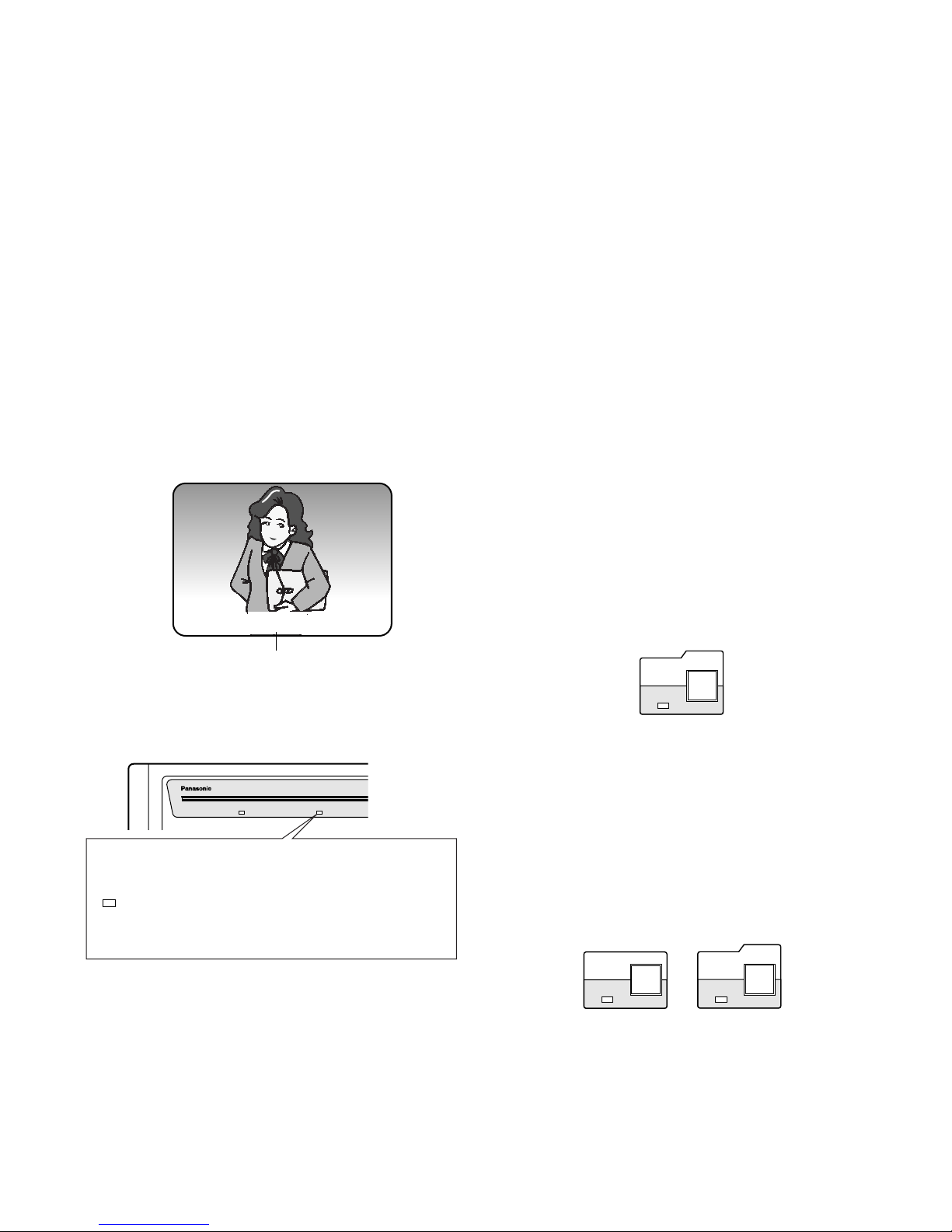
■ Alarm Operation
[ALARM] appears on the monitor screen when the alarm
signal is supplied in the Alarm On mode
The alarm indicator starts to blink and the buzzer sounds.
(ALARM BUZZER is preset to ON at the factory.)
If the preset number is set for the ALARM PRESET or
ALARM TERMINAL parameter in ALARM SETUP menu,
then the camera moves to the preset position when an
alarm is activated. The camera picture at that position is
displayed on the monitor.
The alarm output signal is supplied to the time lapse VTR
until the alarm is reset.
RESET
SUSPEND
ALARM
Character display
(ALARM DISPLAY ON)
ALARM
RESET
SUSPEND
ALARM
SHIFT
OPERATE ALARM
ALARM
Blinking: Alarm has been activated.
Light on: Alarm has been reset automatically
,
or by input signal from external devices
(when the alarm switch is in the upper position).
Light off: Alarm has been reset manually,
or the
ALARM RESET/SUSPEND button has
been pressed while the alarm indicator is on.
 Loading...