

Panasonic WV-CS600, WV-CSR600 User Manual
Combination Camera
WV-BS500 WV-CS600A
WV-BS504E WV-CS604E
WV-BST500 WV-CSR600
WV-CST600
Before attempting to connect or operate this product, please read these instructions completely
WARNING:
TO PREVENT FIRE OR ELECTRIC SHOCK HAZARD, DO NOT EXPOSE THIS APPLIANCE TO RAIN OR
MOISTURE.
The lightning flash with arrowhead
symbol, within an equilateral triangle, is
interned to alert the user to the
presence of uninsulated "dangerous
voltage" within the product's enclosure
that may be of sufficient magnitude to
constitute a risk of electric shock to
persons.
The exclamation point within an
equilateral triangle is intended to alert
the user to the presence of important
operating and maintenance (servicing)
instructions in the literature
accompanying the appliance.
The serial number of this product may be found on the
top of the unit.
You should note the serial number of this unit in the
space provided and retain this book as a permanent
record of your purchase to aid identification in the event
of theft.
Model No.
Serial No.
CAUTION:
TO REDUCE THE RISK OF ELECTRIC SHOCK,
DO NOT REMOVE COVER (OR BACK), NO
USER SERVICEABLE PARTS INSIDE.
REFER SERVICING TO QUALIFIED SERVICE
PERSONNEL.
CAUTION
RISK OF ELECTRIC SHOCK
DO NOT OPEN
ENGLISH VERSION
THIS APPARATUS MUST BE EARTHED.
To ensure safe operation the three-pin plug must be inserted only
into a standard three-pin power point which is effectively earthed
through the normal household wiring. Extension cords used with
the equipment must be three-core and be correctly wired to
provide connection to earth. Wrongly wired extension cords are a
major cause of fatalities.
The fact that the equipment operates satisfactorily does not imply
that the power point is earthed and that the installation is
completely safe. For your safety, if in any doubt about the
effective earthing of the power point, consult a qualified
electrician.
For Australia
For U.K.
FOR YOUR SAFETY PLEASE READ THE FOLLOWING TEXT
CAREFULLY.
This appliance is supplied with a moulded three pin mains plug for your
safety and convenience.
A 13 amp fuse is fitted in this plug.
Should the fuse need to be replaced please ensure that the replacement
fuse has a rating of 13 amp and that it is approved by ASTA or BSI to
BS1362.
Check for the ASTA mark
H or the BSI mark G on the body of the
fuse.
If the plug contains a removable fuse cover you must ensure that it is
refitted when the fuse is replaced.
If you lose the fuse cover the plug must not be used until a replacement
cover is obtained.
A replacement fuse cover can be purchased from your local Panasonic
Dealer.
IF THE FITTED MOULDED PLUG IS UNSUITABLE FOR THE
SOCKET OUTLET IN YOUR HOME THEN THE FUSE SHOULD BE
REMOVED AND THE PLUG CUT OFF AND DISPOSED OF SAFELY.
THERE IS A DANGER OF SEVERE ELECTRICAL SHOCK IF THE
CUT OFF PLUG IS INSERTED INTO ANY 13 AMP SOCKET.
If a new plug is to be fitted please observe the wiring code as shown
below.
If in any doubt please consult a qualified electrician.
WARNING: This apparatus must be earthed.
IMPORTANT
The wires in this mains lead are coloured in accordance with the
following code.
Green-and-yellow: Earth
Blue: Neutral
Brown: Live
As the colours of the wire in the mains lead of this appliance may
not correspond with the coloured markings identifying the terminals in
your plug, proceed as follows.
The wire which is coloured green-and-yellow must be connected to
the terminal in the plug which is marked with the letter E or by the earth
symbol I or coloured green or green-and-yellow.
The wire which is coloured blue must be connected to the terminal
in the plug which is marked with the letter N or coloured black.
The wire which is coloured brown must be connected to the
terminal in the plug which is marked with the letter L or coloured red.
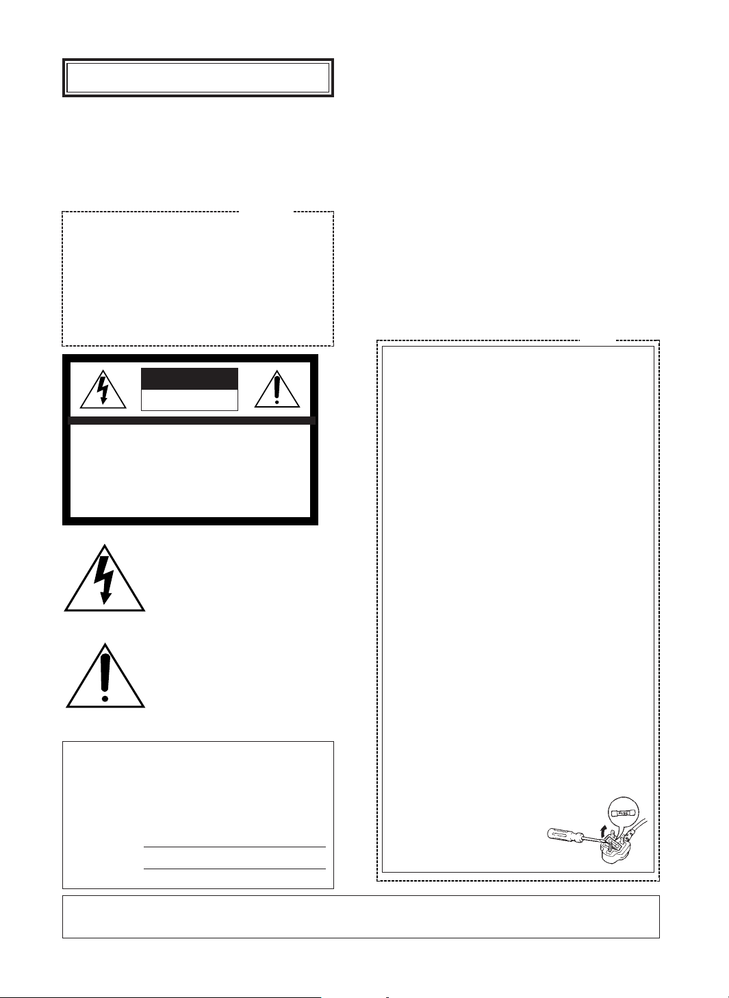
How to replace the fuse
Open the fuse compartment with
a screwdriver and replace the fuse
and fuse cover.


- 1 -
CONTENTS
PREFACE .......................................................... 2
FEATURES ........................................................ 2
PRECAUTIONS ................................................. 2
CONSTRUCTION .............................................. 3
SETUP PROCEDURE ........................................ 4
■ Setup Menu ............................................... 4
■ Setup Menu Description ............................ 6
■ Setting Procedures ...................................... 9
■ Menu Display .............................................. 10
■ Communication Parameter Setting .............. 10
■ Preset ......................................................... 12
■ Deleting Preset Positions ............................ 16
■ Home Position Setting ................................ 16
■ Self Return Setting ...................................... 17
■ Auto Mode Setting ...................................... 17
■ LOCAL/REMOTE Setting ............................ 18
■ Camera Setting ........................................... 18
INSTALLATION ................................................. 30
CONNECTIONS ................................................ 33
SYSTEM CONNECTIONS .................................. 35
PREVENTION OF BLOOMING
AND SMEAR ...................................................... 36
SPECIFICATIONS ............................................... 36
ACCESSORIES ................................................... 38
OPTIONAL ACCESSORIES ................................ 38
The model numbers in these Operating Instructions are given without suffix.
ENGLISH
Wij verklaren als enige aansprakelijke, dat het product
waarop deze verklaring betrekking heeft, voldoet aan de
volgende normen of andere normatiefve dokumenten,
overeenkomstig de bepalingen van Richtlijnen 73/23/EEC
en 89/336/EEC.
Vi erklærer os eneansvarlige for, at dette produkt, som
denne deklaration omhandler, er i overensstemmelse med
den følgende standarder eller andre normative
dokumenter i følge bestemmelserne i direktivene
73/23/EEC og 89/336/EEC.
Vi deklarerar härmed värt fulla ansvar för att den produkt
till vilken denna deklaration hänvisar är i
överensstämmelse med standarddokument, eller andra
normativa dokument som framstölls i Direktiv 73/23/EEC
och 89/336/EEC.
Ilmoitamme yksinomaisella vastuullamme, että tuote, jota
tämä ilmoitus koskee, noudattaa seuraavia standardeja tai
muita ohjeellisia asiakirjoja, jotka noudattavat direktiivien
73/23/EEC ia 89/336/EEC. säädöksiä.
Vi erklærer oss alene ansvarlige for at produktet som
denne erklæringen gjelder for, er i overensstemmelse med
følgende normer eller andre normgivende dokumenter
som fælger bestemmelsene i direktiven 73/23/EEC og
89/336/EEC.
We declare under our sole responsibility that the product
to which this declaration relates is in conformity with the
standards or other normative documents following the
provisions of Directives EEC/73/23 and EEC/89/336.
Noi dichiariamo sotto nostra esclusiva responsabilità che il
prodotto a cui si riferisce la presente dichiarazione risulta
conforme ai seguenti standard o altri documenti normativi
conformi alle disposizioni delle direttive CEE/73/23 e
CEE/89/336.

- 2 -
PREFACE
Panasonic presents highly advanced CCVE
technology meets the demand of new and everchanging applications. This model is utilized video
surveillance device that incorporates a Digital
Signal Processing (DSP) high-performance camera,
pan/tilt mechanism, 10 times zoom lens and
receiver in its compact enclosure.
The camera portion incorporating a high-sensitivity
CCD provides 480-line horizontal resolution for WVCS600A, WV-CS604E, WV-CSR600, and WVCST600 (500-line for WV-BS500, WV-BS504E and
WV-BST500) and an S/N ratio of 48 dB for WVCS600A, WV-CS604E, WV-CSR600 and WVCST600 (46 dB for WV-BS500, WV-BS504E and
WV-BST500). With its advanced digital signal
processing circuit, it is equipped to handle the
surveillance tasks of the coming age.
The pan/tilt portion, allowing 360-degree endless
panning, is designed to meet specific user needs.
This model utilized surveillance device offers
cutting-edge technology for advanced video
surveillance.
FEATURES
1. The following functions are built in.
(1) Auto Light Control (ALC)/Manual Override
Iris
(2) Character Generator
(3) Back Light Compensation (Auto: Factory
preset, Manual: Manual photometric
measuring area set)
(4) Auto/Manual White Balance Function
(5) Electronic Shutter Function
2. Minimum illumination of 3 lx (0.3 foot-candle)
for WV-CS600A, WV-CS604E and WV-CSR600,
6 lx (0.6 foot-candle) for WV-CST600, 0.1 lx
(0.01 foot-candle) for WV-BS500 and WVBS504E, and 0.2 lx (0.02 foot-candle) for WVBST500.
3. High quality picture:
(a) 2H type vertical enhancer for greater
picture sharpness
(b) Chroma averaging circuit for better colour
signal to noise ratio (available only with
WV-CS600A, WV-CS604E, WV-CSR600, or
WV-CST600)
(c) Minimum of aliasing on fine objects
(d) Expanded dynamic range by use of knee
circuit
(e) Highlight aperture correction for greater
picture detail of bright objects
4. Back Light Compensation for use under
unusual lighting conditions.
5. Selectable electronic sensitivity enhancing
modes including : AUTO, MANUAL and OFF
6. Built in Digital Motion Detector
7. 64 preset position-Position, focus, zoom ratio,
rotation mode, etc.
8. 360-degree endless panning.
9. Maximum 240 degrees/second speed from one
position to the next.
10. There is no distance limit for remote access
with the specified extension unit. (only for WVCSR600)
PRECAUTIONS
• Do not attempt to disassemble this unit. There
are no user serviceable parts inside. Refer
servicing to qualified service personnel.
• This unit is designed for indoor use or locations
where it is protected from rain and moisture.
• Be sure to mount on a flat ceiling.
• Do not drop metallic parts through slots. This
could permanently damage this unit. Turn the
power off immediately and refer servicing to
qualified service personnel.
• Wipe the cover regularly with a soft and dry
cloth, or a cloth moistened with a solution of
water and normal kitchen detergent.
Do not use chemicals for cleaning the cover as
it may damage the surface.
• Refer all work related to the installation of this
product to qualified service personnel or
system installers.
• Use this unit in an environment where the
temperature is within
−10°C - +50°C (14°F -
122°F), and the relative humidity within 90%.
• Never aim the camera at bright objects.
Whether the camera is in use or not, never aim
it at the sun, or other extremely bright objects
as this could cause blooming.
• This unit is designed exclusively for ceiling
installation. If installed in standup position, the
picture will be upside down and the pan/tilt
movement will be reversed.
- 3 -
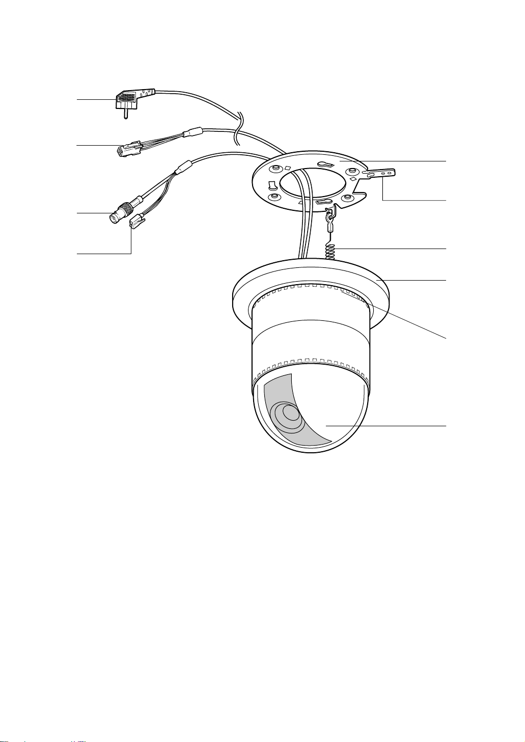
CONSTRUCTION
w
q
e
r
t
y
u
i
o
e
*
(6) Fall Prevention Wire
(7) Decoration Cover
(8) Cooling Holes
(9) Dome Cover
(1) Data Cable (only for WV-CSR600)
(2) Video Output Connector
(3) Power Cable for WV-CS600A, WV-CSR600,
WV-CST600, WV-BS500, and WV-BST500
(3*) Power Cable for WV-CS604E and
WV-BS504E
(4) Camera Mounting Angle
(5) Panning Start Point
- 4 -
Wide Dynamic
Range ON/OFF
Dwell Time
Setting
Scene File
Setting
Camera ID
Display
Position
Preset ID
Display
Position
Preset ON
(Back Light
Compensation)
Shutter
Speed
ON/OFF
AGC
ON/OFF
Preset
Setting
Menu
Position
No.
Selection
MAP
Menu
Camera
ID
Editing
Electronic
Sensitivity
Up ON/OFF
White
Balance
AWC
ATW
Preset
Off
Light
Control
Motion
Detector
ON/OFF
ALC
MANUAL
Preset ON
(Back Light
Compensation)
AF Mode
MANUAL/
AUTO
Manual
Level
Adjustment
(Contrast)
Manual
Mask Area
Selection
Manual
Level
Adjustment
Manual
Level
Adjustment
Sensitivity
Level
Adjustment
Manual
Mask
Area
Selection
Mask
Area
Selection
AF
Area
Selection
Manual
Mask
Area
Selection
Home
Position
Setting
Self
Return
Setting
Auto-pan
Setting
Menu
Auto
Mode
Setting
CAMERA
SET UP MENU
Manual
Manual
Iris
Adjustment
ALC
Preset
OFF
Preset
Menu
Position
Setting
Preset ID
Editing
Light
Control
Setup
Menu
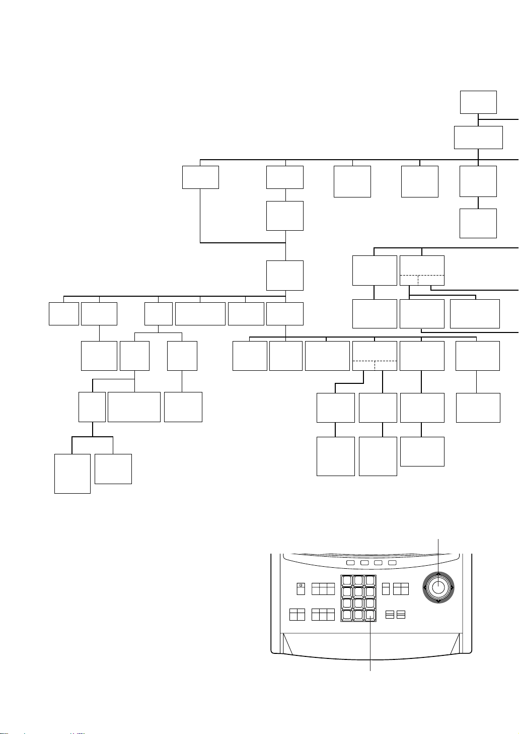
The above menus should be set with the following
switches.
• WV-CU550A
Joystick: Used to move the Cursor
Upward/Downward/Right/ Left
and select the mode.
Also used to adjust the level.
CAM (SET) Key: This key is for setting the mode
and switching between menus.
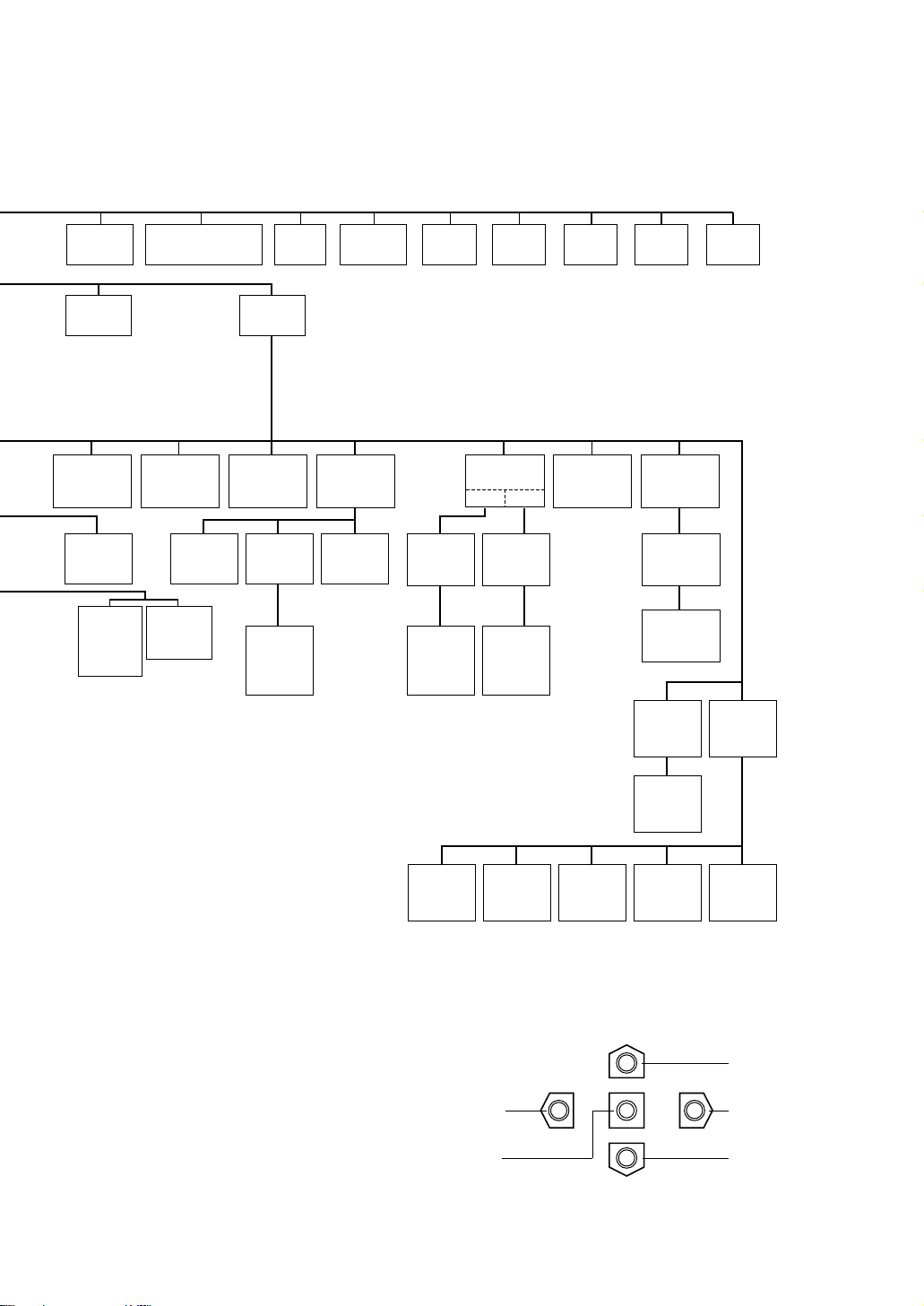
SETUP PROCEDURE
■ Setup Menu
This camera utilizes a user setup menu that is displayed on-screen.
This setup menu contains various sub menus that form a tree-type structure as shown
below.
This menu is described in the "SETUP MENU DESCRIPTION".
1 2 3
4 5 6
7 8 9
MON CAM
ESC SET
0
ACK
RESET
BACK
SEQ
FORWARD
SEQ ALT
DEC
-1CAM
INC
+1CAM
STOP12
AUX
CLOSE
OPEN
IRIS
PRESET
FOCUS
NEAR
ZOOM
TELE
FAR
WIDE
System Controller WV-CU 550A
LEFT
RIGHT
UP
DOWN
F3 F4F2F1
AF
Joystick
CAM (SET) Key
- 5 -
Left Switch
Set Switch
Right Switch
Down Switch
Up Switch
• WV-RM70
(available with all models except WV-CSR600)
Up Switch: Moves the cursor upwards.
Down Switch: Moves the cursor downwards.
Right Switch: Moves the cursor right. This
switch also selects the mode
and can be used to adjust
certain Levels.
Left Switch: Moves the cursor left. This
switch also selects the mode
and can be used to adjust
certain Levels.
Set Switch: This switch is for setting the
mode and switching between
menus.
Note:
The menus described in bold are displayed
only when WV-CSR600 is used.
Shutter
Speed
ON/OFF
Manual
Level
Adjustment
(Contrast)
Manual
Mask Area
Selection
Manual
Iris
Adjustment
AGC
ON/OFF
Sensitivity
Up
ON/OFF
Sync.
INT/LL
Wide
Dynamic
Range
Motion
Detector
ON/OFF
White
Balance
AWC
ATW
INT
Manual
Selection
LL
Manual
Selection
VD2
Automatic
Selection
Manual
Level
Adjustment
Manual
Level
Adjustment
Sensitivity
Level
Adjustment
Manual
Mask
Area
Selection
Mask
Area
Selection
Manual
Mask
Area
Selection
V-phase
Manual
Adjustment
Local/
Remote
Camera
Menu
Special
Menu
AF Mode
Manual/
Auto
AF
Area
Selection
Camera
Reset
PedestalAP GainChroma
Gain
Up
Side
Down
UNIT
NUMBER
TRANSMISSION
SPEED
DATA
BIT
PARITY
BIT
STOP
BIT
XON/
XOFF
ALARM
DATA
DELAY
TIME
WAIT
TIME

■ Setup Menu Description
● RS485 site communication (only WV-CSR600)
Communication parameters
• Full/Half duplex (page 30)
• Transmission speed (2400 - 19200 bps) (page 11)
• Parity check, Stop bit, Characters, Flow control (page 11)
• Retransmit time, Delay time, Alarm output (page 11)
• Camera units (96 units max.) (page 30)
• Termination ON/OFF (page 30)
• Reset parameters (page 30)
● PRESET
(1) Position (POSITION SET)
POSITION SET adjusts the camera picture by panning, tilting, zooming and focusing.
See page 13 for the setting.
(2) Preset Identification (PRESET ID)
A preset ID (identification of up to 16 alphanumeric characters) can be displayed on the screen.
See page 14 for the setting.
(3) Light Control (ALC/MANUAL)
ALC/MANUAL refers to the mode of the incoming light level control.
See page 15 for the setting.
(4) Wide-Dynamic Range (WIDE D-RANGE)
WIDE D-RANGE is used to enhance picture viewing. This function is useful, for example, when a picture is
too dark or too bright to watch the object because the lighting conditions are too dim or too bright.
See page 15 for the setting.
(5) Dwell Time (DWELL TIME)
DWELL TIME is the duration that the picture of each camera position is displayed. You can select a preset
duration from the menu.
See page 15 for the setting.
(6) Scene File (SCENE FILE)
SCENE FILE is used to memorize the camera shooting scene. You can store up to 10 (scene file No. 1 to
No. 10) camera shooting scenes. The camera functions below are available for detail setting of the scene
files to be stored. These functions are stored in memory together with the scene files.
Camera functions available for detail setting of scene files are: shutter speed, AGC, electronic sensitivity
enhancement, white balance, motion detector and AF mode.
See page 15 for the setting.
● Home Position (HOME POSITION)
HOME POSITION is the camera’s basic position. It returns to this position automatically, when a specified time
has elapsed after a manual operation.
See page 16 for the setting.
● Self Return (SELF RETURN)
SELF RETURN is the time-out parameter for returning to the home position.
See page 17 for the setting.
- 6 -

- 7 -
● AUTO MODE
AUTO MODE is for setting the movement of the camera. You can select from three automatic operation modes
and one manual operation mode as follows:
OFF mode: No automatic operation. The camera can be operated only manually.
SEQ mode: The camera operates in the sequence of preset positions in numerical order.
SORT mode: The camera operates in the sequence of preset positions counterclockwise from Pan/Tilt Starting
Point.
AUTO PAN mode: The camera automatically turns within the preset panning range.
See page 17 for the setting.
● LOCAL/REMOTE
LOCAL/REMOTE determines the relationship between camera operation and ON/OFF status of the controller.
You can select one of the following two modes:
LOCAL: The camera continues operating in auto mode when the controller is turned OFF.
REMOTE: The camera stops operating in auto mode approx. 1 minute after the controller is turned off.
See page 18 for the setting.
● Camera
(1) Camera Identification (CAMERA ID)
You can use the camera identification (CAMERA ID) to assign a name to the camera. The camera ID
consists of up to 16 alphanumeric characters. You can select whether to have the camera ID displayed on
the monitor screen or not.
Note:
See page 19 for the setting.
(2) Light Control (ALC/MANUAL)
You can select the mode for adjusting the lens iris.
The modes are as follows:
ALC: The lens iris is automatically adjusted according to the brightness of the object.
MANUAL: The lens iris is fixed at the value you have set regardless of the brightness of the object.
• Back Light Compensation (BACK LIGHT COMP)
Back light compensation is available in ALC mode. It eliminates interference by strong background lighting
which makes the camera picture dark, such as a spotlight. You can select one of two modes (PRESET ON
or PRESET OFF) for back light compensation.
This function is disabled in MANUAL mode.
• Factory Setup Mode (PRESET ON)
In normal use the important object in a scene is placed in the centre of the monitor's screen. In the factory
setup mode, more photometric weight is given to the centre of the screen (where the important object is
located) than to the edge of the picture (where a bright back light would most likely be located). In this
mode, even though the back light may vary, the object at the centre of the screen can still be clearly seen.
Note:
See page 20 for the setting.
• Field Setup Mode (PRESET OFF)
This mode is effective when the main object in the scene is not located in the centre of the screen and a
source of bright light is located near the centre of the screen. In this mode, the picture is divided into 48
areas. If there is a source of brightness that interferes with the clarity of the picture in these masks,
corresponding areas mask the light to keep the clarity of the picture.
Generally, when a light from the background is too strong such as a spotlight, all objects except the main
object in the picture are displayed darker because the lens iris is adjusted with respect to strong
brightness. This model ignores strong brightness by masking the source of the strong brightness, thereby
all objects are displayed clearly.

- 8 -
Note:
The result of field setup of the mask area and level adjustment is fed back (effected) to the lens iris
control in ALC mode.
(3) Shutter Speed (SHUTTER)
You can select the shutter speed from 1/50 (OFF), 1/120, 1/250, 1/500, 1/1000, 1/2000. 1/4000, and
1/10000 second.
Note:
See page 21 for the setting.
(4) Gain Control (AGC)
You can set the gain (brightness level portion of an image) to automatic adjustment (Automatic Gain
Control ON) or fixed (Automatic Gain Control OFF).
Note:
See page 22 for the setting.
(5) Electronic Sensitivity Enhancement (SENS UP)
The electronic sensitivity emhancement (SENS UP) function varies the shutter speed to raise the sensitivity
in low light conditions when OFF is selected for ALC.
You can select the shutter speed for SENS UP from the preset values as follows;
1/30 seconds (x2), 1/15 seconds (x4), 1/10 seconds (x6), 1/6 seconds (x10), 1/3.8 seconds (x16), or 1/1.9
seconds (x32).
There are two modes for SENS UP as follows;
AUTO: If you select x32, for example, the sensitivity is raised automatically to x32 max.
FIX: If you select x32, for example, the sensitivity is raised to just x32.
Notes:
• See page 22 for the setting.
• Moving objects will appear blurred when shot during the electronic sensitivity enhancement mode
since SENS UP is equivalent to setting the shutter speed to a slower speed in a still picture camera.
• The horizontal and vertical resolution will be lowered in this mode.
• If the video output level is adjusted too low (the iris opening is too small), the Electronic Sensitivity
Enhancement (SENS UP)/AUTO mode will not function. Select ALC PRESET ON in this condition.
(6) Synchronization (SYNC)
You can select internal sync mode (INT) or line-lock sync (LL). Additionally, this model accepts the VD2
signal (multiplexed vertical drive signal) with the composite video output signal from a specified
component. Whenever the VD2 signal is supplied to this camera, the camera automatically switches to the
VD2 sync mode.
When you select line-lock sync (LL), you can set vertical phase adjustment for composite sync mode or
horizontal and sub-carrier phase adjustments for the black burst mode.
Important Notice:
The priority of sync modes is as follows:
1. Multiplexed Vertical Drive (VD2) (Highest)
2. Line-lock (LL)
3. Internal Sync (INT) (Lowest)
Note:
The priority of automatic sync mode is the same as shown above. See page 22 for the setting.
(7) White Balance (WHITE BAL)
(available only with WV-CS600A, WV-CS604E, WV-CSR600, or WV-CST600)
You can select one of two modes for white balance adjustment as follows:

- 9 -
• ATW (Auto Tracing White Balance)
In this mode, the colour temperature is monitored continuously and thereby white balance is set
automatically. The colour temperature range for the proper white balance is approximately 2,600-6,000K.
Proper white balance may not be obtained under the following conditions:
1. The colour temperature is out of the 2,600-6,000K range.
2. When the scene contains mostly high colour temperature (bluish) objects, such as a blue sky or
sunset.
3. When the scene is dim.
In these cases, select the AWC mode.
• AWC (Automatic White Balance)
In this mode, accurate white balance is obtained within a colour temperature range of approx. 2,300 10,000K.
Note:
See page 25 for the setting.
(8) Wide Dynamic Range (WIDE D-RANGE)
Wide Dynamic Range makes it easier to monitor the picture when the lighting conditions in the location
where the camera is installed are too dim or too bright. You can select wide dynamic range (WIDE DRANGE ON) or normal dynamic range (WIDE D-RANGE OFF).
Notes:
• Use of the Wide Dynamic Range mode might not be appropriate when the scene consists mostly of
dark objects as this may result in a picture with a significant amount of noise.
• See page 25 for the setting.
(9) Motion Detector (MOTION DET)
The Motion Detector detects the motion in the scene by monitoring changes in the brightness level. You
can select the level of sensitivity for motion on the SET UP menu.
When this camera is connected to a compatible intelligent CCVE system, the camera transmits an alarm
signal by multiplexing it with the video signal.
When the camera detects the motion in AUTO, it supplies the alarm signal to the external equipment and
stops at its position for the preset dwell time. You can select the dwell time as follows;
OFF 1/2/3/5/10/20/30/60 min.
Note:
See page 26 for the setting.
(10) Auto Focus (AF MODE)
You can select one of two AF modes as follows:
MANUAL: AF mode is activated by pressing the AF button of the controller.
AUTO: AF mode is activated automatically after a manual panning, tilting or zooming operation.
Notes:
• AUTO in AF MODE is disabled unless SENS UP is set to OFF. If SENS UP is not OFF, AF MODE is set
automatically to MANUAL.
• See page 27 for the setting.
(11) Special Menu (SPECIAL)
This menu allows you to adjust the following items: upside down, chroma level, aperture level and pedestal
level. You can also reset your parameters to the values preset at the factory.
See page 28 for the setting.
■ Setting Procedures
The following setting procedures are described on the assumption that this model is used in combination with
the WJ-SX550A matrix switcher and WV-CU550A system controller. If used with the WV-RM70 camera
controller, refer to “WV-RM70” on page 5 for operation.
- 10 -
*** SET UP MENU ***
PRESET 1*
MAP*
HOME POSITION 15
SELF RETURN 10MIN
AUTO MODE OFF
LOCAL/REMOTE LOCAL
CAMERA *
Setup menu
(for camera setting)
3. Press the F1 button.
The SET UP MENU appears on the monitor.
4. To close the SET UP MENU, press the F4 button.
Note:
Do not change the SET UP MENU (for camera communication)
settings of the WV-CSR600 except CAMERA*. If those settings
are changed, the camera and the controller may get out of
control.
*** SET UP MENU ***
CAMERA*
UNIT NUMBER
BAUD RATE 19200
DATA BIT 8
PARITY BIT NONE
XON/XOFF NOT USE
WAIT TIME OFF
ALARM DATA AUTO 2
DELAY TIME OFF
COM. SET UP DISABLE
Setup menu
(for camera communication)
(only for WV-CSR600)
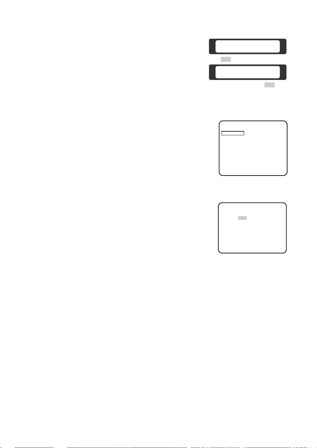
■ Menu Display
● Setup Menu Display
1. Select the number of the camera you want to set up and a monitor to
display the SET UP MENU.
2. Display the D4 menu on the LCD by pressing the appropriate cursor
buttons.
D4 menu
F1
F1 F2 F3 F4
Camera Set Up Menu
Res A.Res Exit
F2 F3 F4
Camera Set Up Menu
On Exit
■ Communication Parameter Setting
● Initial camera communication parameters
• Confirm the communication parameters of the matrix switcher (WJ-SX550A), and display the camera SET
UP MENU.
The initial camera communication parameters are shown in illustration above.
The other parameters are as follows:
Daisy : OFF
Camera In Number : 1
F/H Duplex : Full
● Changing the camera communication parameters
1. Display the SET UP MENU. Move the cursor to COM. SET UP DISABLE and press the CAM (SET) key to
select COM. SET UP ENABLE.
2. Move the cursor to the item and select the parameter by moving the joystick to the left or right.
● Submenu Display
The items marked * can be selected/changed on the submenu.
• Move the cursor to an item with the * mark and press the CAM (SET)
key. The submenu is displayed.
Note:
When you use the WV-CSR600, move the cursor to CAMERA on
the SET UP MENU and press the CAM (SET) key. The SET UP
MENU for camera setting appears in the display.
 Loading...