

Page 1
Color CCTV Camera
Operating Instructions
Model No. WV-CS954
Before attempting to connect or operate this product,
please read these instructions carefully and save this manual for future use.
FRANÇAIS ENGLISH
Page 2
ENGLISH VERSION
CAUTION
RISK OF ELECTRIC SHOCK
DO NOT OPEN
CAUTION: TO REDUCE THE RISK OF ELECTRIC SHOCK,
DO NOT REMOVE COVER (OR BACK).
NO USER-SERVICEABLE PARTS INSIDE.
REFER SERVICING TO QUALIFIED SERVICE PERSONNEL.
For U.S.A
NOTE: This equipment has been tested and found to comply
with the limits for a Class A digital device, pursuant to Part
15 of the FCC Rules. These limits are designed to provide
reasonable protection against harmful interference when the
equipment is operated in a commercial environment. This
equipment generates, uses, and can radiate radio frequency
energy and, if not installed and used in accordance with the
instruction manual, may cause harmful interference to radio
communications.
Operation of this equipment in a residential area is likely to
cause harmful interference in which case the user will be
required to correct the interference at his own expense.
FCC Caution: To assure continued compliance, (example use only shielded interface cables when connecting to
computer or peripheral devices). Any changes or modifications not expressly approved by the party responsible for
compliance could void the user’s authority to operate this
equipment.
The lightning flash with arrowhead
symbol, within an equilateral triangle, is
intended to alert the user to the
presence of uninsulated "dangerous
This Class A digital apparatus complies with Canadian
ICES-003.
For Canada
voltage" within the product's enclosure
that may be of sufficient magnitude to
SA 1965
constitute a risk of electric shock to
persons.
The exclamation point within an
equilateral triangle is intended to alert
the user to the presence of important
operating and maintenance (servicing)
instructions in the literature accompanying the appliance.
SA 1966
WARNING: To prevent fire or electric shock hazard, do not expose this appliance to rain or moisture. The apparatus shall not be exposed
to dripping or splashing and that no objects filled with liquids, such as vases, shall be placed on the apparatus.
The serial number of this product may be found on the top
of the unit.
You should note the serial number of this unit in the space
provided and retain this book as a permanent record of your
purchase to aid identification in the event of theft.
Model No. WV-CS954
Serial No.
-2-
Page 3
IMPORTANT SAFETY INSTRUCTIONS
1) Read these instructions.
2) Keep these instructions.
3) Heed all warnings.
4) Follow all instructions.
5) Do not use this apparatus near water.
6) Clean only with dry cloth.
7) Do not block any ventilation openings. Install in accordance with the manufacturer's instructions.
8) Do not use near any heat sources such as radiators, heat registers, stoves, or other apparatus (including
amplifiers) that produce heat.
9) Do not defeat the safety purpose of the polarized or grounding-type plug. A polarized plug has two blades with
one wider than the other. A grounding-type plug has two blades and a third grounding prong. The wide blade or
the third prong are provided for your safety. If the provided plug does not fit into your outlet, consult an
electrician for replacement of the obsolete outlet.
10) Protect the power cord from being walked on or pinched particularly at plugs, convenience receptacles and the
points where they exit from the apparatus.
11) Only use attachments/accessories specified by the manufacturer.
12) Use only with the cart, stand, tripod, bracket, or table specified by the manufacturer, or sold with the apparatus.
When a cart is used, use caution when moving the cart/apparatus combination to avoid injury from tip-overs.
S3125A
13) Unplug this apparatus during lightning storms or when unused for long periods of time.
ENGLISH
14) Refer all servicing to qualified service personnel. Servicing is required when the apparatus has been damaged
in any way, such as power-supply cord or plug is damaged, liquid has been spilled or objects fallen into the
apparatus, the apparatus has been exposed to rain or moisture, does not operate normally, or has been
dropped.
-3-
Page 4

LIMITATION OF LIABILITY
THIS PUBLICATION IS PROVIDED “AS IS” WITHOUT
WARRANTY OF ANY KIND, EITHER EXPRESS OR
IMPLIED, INCLUDING BUT NOT LIMITED TO, THE
IMPLIED WARRANTIES OF MERCHANTABILITY,
FITNESS FOR ANY PARTICULAR PURPOSE, OR NONINFRINGEMENT OF THE THIRD PARTY'S RIGHT.
DISCLAIMER OF WARRANTY
IN NO EVENT SHALL MATSUSHITA ELECTRIC
INDUSTRIAL CO., LTD. BE LIABLE TO ANY PARTY OR
ANY PERSON, EXCEPT FOR REPLACEMENT OR
REASONABLE MAINTENANCE OF THE PRODUCT,
FOR THE CASES, INCLUDING BUT NOT LIMITED TO
BELOW:
(1) ANY DAMAGE AND LOSS, INCLUDING WITH-
OUT LIMITATION, DIRECT OR INDIRECT, SPECIAL, CONSEQUENTIAL OR EXEMPLARY,
ARISING OUT OF OR RELATING TO THE
PRODUCT;
(2) PERSONAL INJURY OR ANY DAMAGE
CAUSED BY INAPPROPRIATE USE OR NEGLIGENT OPERATION OF THE USER;
(3) UNAUTHORIZED DISASSEMBLE, REPAIR OR
MODIFICATION OF THE PRODUCT BY THE
USER;
THIS PUBLICATION COULD INCLUDE TECHNICAL
INACCURACIES OR TYPOGRAPHICAL ERRORS.
CHANGES ARE ADDED TO THE INFORMATION
HEREIN, AT ANY TIME, FOR THE IMPROVEMENTS OF
THIS PUBLICATION AND/OR THE CORRESPONDING
PRODUCT(S).
(4) INCONVENIENCE OR ANY LOSS ARISING
WHEN IMAGES ARE NOT DISPLAYED, DUE TO
ANY REASON OR CAUSE INCLUDING ANY
FAILURE OR PROBLEM OF THE PRODUCT;
(5) ANY PROBLEM, CONSEQUENTIAL INCONVE-
NIENCE, OR LOSS OR DAMAGE, ARISING OUT
OF THE SYSTEM COMBINED BY THE DEVICES
OF THIRD PARTY.
(6) ANY CLAIM OR ACTION FOR DAMAGES,
BROUGHT BY ANY PERSON OR ORGANIZATION BEING PHOTOGENIC SUBJECT, DUE TO
VIOLATION OF PRIVACY WITH THE RESULT OF
THAT SURVEILLANCE-CAMERA's PICTURE,
INCLUDING SAVED DATA, FOR SOME REASON, BECOMES PUBLIC OR IS USED FOR THE
PURPOSE OTHER THAN SURVEILLANCE.
(7) ANY PROBLEM, CONSEQUENTIAL INCONVE-
NIENCE, ANY LOSS OR DAMAGE, ARISING
OUT OF THE IMPROPER DETECTION OR SLIPUP IN DETECTION BY VMD (Video Motion
Detector) FUNCTION OF THE PRODUCT.
-4-
Page 5
FEATURES
This Color CCTV Camera is a video surveillance device
that incorporates a 1/4-type {1/4"} CCD, a 30x zoom
lens, preset and pan and tilt capabilities in a dome
configuration. It also has the following features.
■ Super Dynamic 33(SUPER-D 33)
SUPER-D 3 makes it possible to capture clear images
of subjects whose illumination is extremely different.
■ New DSP for High Sensitivity
A new noise reduction system lowers minimum
illuminance to 0.5 lux{fc} in the color mode and 0.04
lux{fc} in the black and white mode.
■ Auto Nighttime Switching to Black
and White Mode
The camera can be configured to switch to the black
and white mode automatically under low light conditions for clear images, even at night.
■ Digital Flip
Normally, a camera needs to stop when it points
straight down during a tilt operation. With digital flip,
however, the camera is able to tilt from 0° to 180° in a
single motion. This makes it possible to track subjects
passing directly under the camera more smoothly.
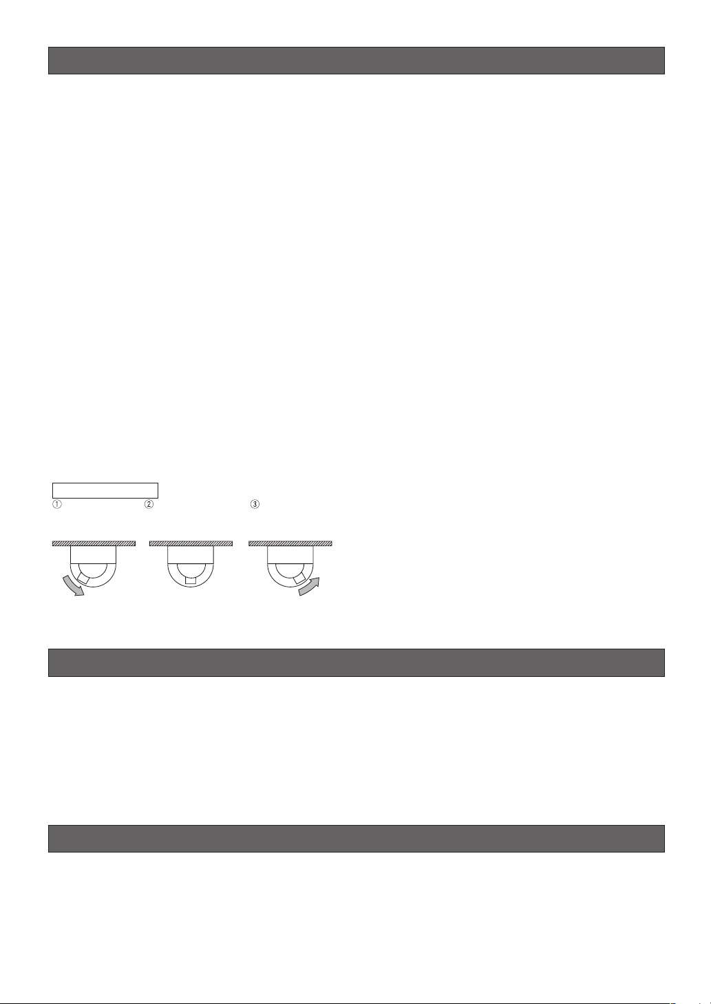
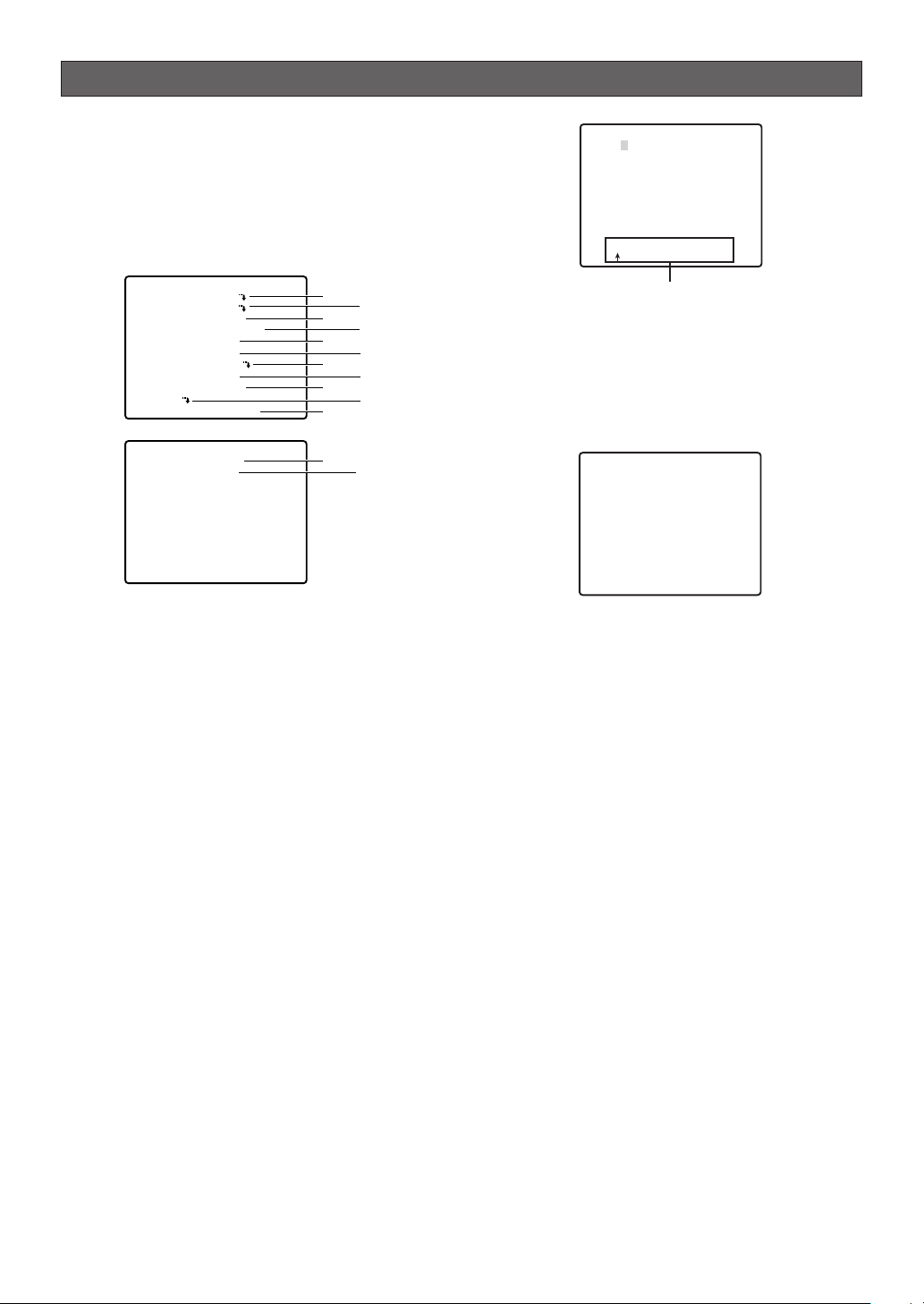
Digital Flip Operation
Tilting
downwards
The picture is flipped
when the camera is
pointing straight down
(at around 135°).
Tilting upwards.
■ Privacy Zone Function
The privacy zone function makes it possible to mask
specific areas of the scene from view.
■ Patrol Function
The patrol function remembers manual camera movement routines for automatic playback when they are
needed. For example, you can teach the camera the
movements of the people you want to monitor, by
replaying the stored parameters complicated movements are done automatically.
■ Camera Position Memory
The system can be configured with up to 256 camera
positions. A particular camera position can be selected
and viewed by entering the applicable preset number
on the system controller 10-key pad.
■ Motion Detection
The system can be configured so any motion on the
monitor screen during surveillance causes output of an
alarm signal.
This function can be used to structure a system with a
VCR that records images of nighttime intruders.
· · · Digital flip is performed only when the system controller joystick is held downwards.
ACCESORIES
Operating Instructions (this manual) . . . . . . . . . .1 pc.
Warranty Certificate . . . . . . . . . . . . . . . . . . . . . . .1 pc.
The following items are for installation.
Decorative Cover . . . . . . . . . . . . . . . . . . . . . . . . .1 pc.
Dust Protection Sheet . . . . . . . . . . . . . . . . . . . . . .1 pc.
8P Alarm Cable . . . . . . . . . . . . . . . . . . . . . . . . . . .1 pc.
4P Alarm Cable . . . . . . . . . . . . . . . . . . . . . . . . . . .1 pc.
Connector for 24 V AC . . . . . . . . . . . . . . . . . . . . .1 pc.
OPTIONAL ACCESORIES
Dome Cover(approx.50 % transparency,smoked type) . . . . . . .WV-CS3S
Ceiling Mount Bracket . . . . . . . . . . . . . . . . . . . . . . . . . . . . . . . . .WV-Q105/WV-Q116/WV-Q117
Wall Mount Bracket . . . . . . . . . . . . . . . . . . . . . . . . . . . . . . . . . . .WV-Q118
-5-
Page 6

PRECAUTIONS
1. Do not attempt to disassemble the camera.
To prevent electric shock, do not remove screws or
covers.
There are no user-serviceable parts inside.
Ask qualified service personnel for servicing.
2. Handle the camera with care.
Do not misuse the camera. Avoid striking, shaking,
etc. The camera could be damaged by improper
handling or storage.
3. Do not expose the camera to rain or moisture,
nor try to operate it in wet areas.
This product is designed for indoor use or locations
where it is protected from rain and moisture.
Turn the power off immediately and ask qualified
service personnel for servicing.
Moisture can damage the camera and also create
the danger of electric shock.
4. Do not use strong or abrasive detergents when
cleaning the camera body.
Use a dry cloth to clean the camera when it is dirty.
When the dirt is hard to remove, use a mild
detergent and wipe gently. Care should be taken
not to scratch the dome cover when wiping it.
Afterwards, wipe off the remaining detergent with a
dry cloth.
5. Never aim the camera at the sun.
Whether or not the camera is in use , never aim it at
the sun or other extremely bright objects.
Otherwise, blooming or smear may be caused.
6. Never aim the camera at strong light sources for
an extended period of time.
A light source such as a spot light causes burn-in
on the display screen. Failure to observe this may
cause the image to become discolored due to
deterioration of the color filter in the CCD.
7. Do not install this camera upside down.
This camera is designed for mounting on the ceiling
or wall. Using this camera installed upside down,
for example, mounted on the floor, may cause
malfunction.
8. Do not operate the camera beyond the specified
temperature, humidity or power source ratings.
Do not use the camera in an extreme environment
where high temperature or high humidity exists. Do
not place the camera near heat sources such as
radiators, stoves or other units that produce heat.
Use the camera under conditions where temperature is between –10 °C - +50 °C {14 °F - 122 °F},
preferably +40 °C {104 °F}, and humidity is below
90 %.
The input power source is 24 V AC 60 Hz.
9. Do not install the camera near the air outlet of an
air conditioner.
The lens may become cloudy due to condensation
if the camera is used under the following
conditions.
• Rapid temperature fluctuations by switching the air
conditioner on and off.
• Rapid temperature fluctuations due to frequent door
opening and closing.
• Use in an environment where eyeglasses become
foggy.
• Use in a room filled with cigarette smoke or dust.
If the lens becomes cloudy due to condensation,
remove the dome cover and wipe all moist surfaces
with a soft cloth.
10.Consumables
Parts having contacts such as the lens-drive
motors, cooling fan motor and slip-rings inside the
camera are subject to wear with time. Please ask
the nearest service center about replacement and
maintenance of such parts.
11.Do not aim the camera at the same object for a
long time.
Burn-in of an image may be caused on the
fluorescent screen of CRT.
12.Self-diagnosis Function
If the camera continues operating abnormally for 30
seconds or more due to such an accident as
external noise, the camera will automatically reset
its power. In the case it happens frequently, check
if there would be any environmental cause.
* Matsushita Electric Industrial Co., Ltd. herewith
declares that it will not be liable for any damage,
whether direct or indirect, caused by using the
product for business transaction or security, or
malfunctioning of this product.
-6-
Page 7

OPERATING PRECAUTIONS
■ The camera does not have a power switch
Power turns on as soon as the power cord is plugged
into a power outlet. Before cleaning the camera,
unplug the power cord from the power outlet.
■ What to do if OVER HEAT appears on the display
This message indicates that the interior of the camera
has become very hot. Immediately unplug the power
cord from the power outlet, and contact a qualified
service person or system installer.
■ Note the following to ensure long-term trouble-
free operation
Long operation under high temperatures and high
humidity can cause components to deteriorate and
shorten camera life.
The recommended ambient operation temperature is
less than +35 °C.
Make sure the camera is installed in a location where it
is not directly exposed to heat from a radiator, heater,
etc.
■ Avoid use of this camera in a food preparation
area and other locations where there are large
amounts of steam vapor and oil.
■ About the Camera Cleaning Function
Prolonged use can lead to noise on the monitor and
divergence of preset positions.
If such conditions persist even after you perform
camera cleaning (page 35), use the special setup
menu to execute the “REFRESH” operation (page 39).
If you are using a matrix switcher with a camera
cleaning function (WJ-SX550C), configure the matrix
switcher Auto Cleaning settings so cleaning is
performed once a day.
■ This camera is designed for use in a hanging
configuration only.
Do not use it in an upright configuration on a tabletop,
floor, etc. Such conditions create the risk of
malfunction.
■ CCD color filter burn-in
Intense light concentrated on one spot for a long
period can cause deterioration of the CCD internal
color filters, and discoloration of the affected part. Even
if the camera position is changed from a fixed position,
the discoloration at the previous location of the
concentrated light will remain on the screen.
■ Do not point the camera at a strong light source.
Intense light such as that produced by a spotlight
concentrated on one part of the screen can cause
blooming (rainbow around the strong light) or smearing
(vertical stripes above and below the strong light).
Bright Subject
Smearing
Blooming
■ Do not aim the camera at the same object for a
long time.
Burn-in of an image may be caused on the fluorescent
screen of CRT.
■ Handle the camera carefully.
Do not drop the camera, or subject it to strong impact
or vibration. Such conditions create the risk of
malfunction.
■ Do not allow the camera to become wet.
Make sure that it is not exposed directly to water. Such
conditions create the risk of malfunction.
■ Condensation inside of the dome cover
Remove the dome cover and use a soft cloth to wipe
off the moisture.
■ Consumables
Parts having contacts such as the lens-drive motors,
cooling fan motor and slip-rings inside the camera are
subject to wear with time. Please ask the nearest
service center about replacement and maintenance of
such parts.
■ Cleaning the camera
Turn off the camera and wipe it with a soft cloth. If the
camera is very dirty, wipe it off gently with a soft cloth
moistened with a weak solution of water and a neutral
kitchen detergent. Wring all excess liquid from the
cloth before wiping the camera. Next, wipe off all
remaining solution with a soft, dry cloth.
A dirty dome cover or lens causes deterioration of
picture quality. Use lens cleaning paper (like the type
available for cleaning eyeglasses or a camera lens) to
clean the lens.
The dome cover is particularly susceptible to damage.
Gently wipe it with a soft cloth.
-7-
Page 8

■ Downloading (saving) or uploading (recovering)
camera setting information
Camera setting information that can be downloaded to
the system controller etc, includes existing preset
position settings and menu settings. However, the
following items are not included.
• Patrol function (page 32)
• Area title function (page 34)
• Blemish compensation pattern (page 39)
• RS485 settings (page 20)
• Password settings (page 42)
Make sure that the functions listed below are all turned
off before downloading camera preset data to the
system controller etc. or uploading downloaded data to
the camera. Download or upload will not end normally
if it is performed while any of these functions are turned
on.
•Alarm (page 37)
• Preset Alarm (page 37)
• Cleaning (page 35)
• Motion Detector (page 36)
• Auto Mode (page 30)
• Self Return (page 30)
When downloading or uploading preset data, aim the
camera at a wall or similar object so there is as little
movement as possible on the screen.
Uploading of WV-CS954 preset data to other models
(e.g. WV-CS854, WV-CS854A, WV-CS854B and WVNS324) may cause an error and failure of the
uploading process.
■ Self-diagnosing Function
If abnormal operation due to external noise or some
other reason continues for more than 30 seconds, the
camera will automatically reset itself and restore
normal operation. Reset operation the same
initialization routine that is performed when the camera
is turned on. If the reset is required too often, it could
mean that the camera is installed in a location where
there is a large amount of external noise. This can
cause malfunction of the camera, so you should
contact a qualified service person or system installer
as soon as possible.
-8-
Page 9

CONTENTS
IMPORTANT SAFETY INSTRUCTIONS . . . . . . . . . . . . . . . . . . . . . . . . . . . . . . . . . . . . . . . . . .3
LIMITATION OF LIABILITY . . . . . . . . . . . . . . . . . . . . . . . . . . . . . . . . . . . . . . . . . . . . . . . . . . . .4
DISCLAIMER OF WARRANTY . . . . . . . . . . . . . . . . . . . . . . . . . . . . . . . . . . . . . . . . . . . . . . . . .4
FEATURES . . . . . . . . . . . . . . . . . . . . . . . . . . . . . . . . . . . . . . . . . . . . . . . . . . . . . . . . . . . . . . . .5
■ Super Dynamic 3 (SUPER-D 3) . . . . . . . . . . . . . . . . . . . . . . . . . . . . . . . . . . . . . . . . . . .5
■ New DSP for High Sensitivity . . . . . . . . . . . . . . . . . . . . . . . . . . . . . . . . . . . . . . . . . . . . . .5
■ Auto Nighttime Switching to Black and White Mode . . . . . . . . . . . . . . . . . . . . . . . . . . . .5
■ Digital Flip . . . . . . . . . . . . . . . . . . . . . . . . . . . . . . . . . . . . . . . . . . . . . . . . . . . . . . . . . . . .5
■ Privacy Zone Function . . . . . . . . . . . . . . . . . . . . . . . . . . . . . . . . . . . . . . . . . . . . . . . . . . .5
■ Patrol Function . . . . . . . . . . . . . . . . . . . . . . . . . . . . . . . . . . . . . . . . . . . . . . . . . . . . . . . . .5
■ Camera Position Memory . . . . . . . . . . . . . . . . . . . . . . . . . . . . . . . . . . . . . . . . . . . . . . . . .5
■ Motion Detection . . . . . . . . . . . . . . . . . . . . . . . . . . . . . . . . . . . . . . . . . . . . . . . . . . . . . . .5
ACCESORIES . . . . . . . . . . . . . . . . . . . . . . . . . . . . . . . . . . . . . . . . . . . . . . . . . . . . . . . . . . . . .5
OPTIONAL ACCESORIES . . . . . . . . . . . . . . . . . . . . . . . . . . . . . . . . . . . . . . . . . . . . . . . . . . . .5
PRECAUTIONS . . . . . . . . . . . . . . . . . . . . . . . . . . . . . . . . . . . . . . . . . . . . . . . . . . . . . . . . . . . .6
OPERATING PRECAUTIONS . . . . . . . . . . . . . . . . . . . . . . . . . . . . . . . . . . . . . . . . . . . . . . . . .7
CONSTRUCTION . . . . . . . . . . . . . . . . . . . . . . . . . . . . . . . . . . . . . . . . . . . . . . . . . . . . . . . . . .10
INSTALLATION PRECAUTIONS . . . . . . . . . . . . . . . . . . . . . . . . . . . . . . . . . . . . . . . . . . . . . .11
DIP SWITCH SETTINGS . . . . . . . . . . . . . . . . . . . . . . . . . . . . . . . . . . . . . . . . . . . . . . . . . . . .12
■ Communication Parameters (DIP Switch 2) . . . . . . . . . . . . . . . . . . . . . . . . . . . . . . . . . .12
■ Unit Number (DIP Switch 1) . . . . . . . . . . . . . . . . . . . . . . . . . . . . . . . . . . . . . . . . . . . . . .13
■ RS485 Communication Parameters (DIP Switch 1) . . . . . . . . . . . . . . . . . . . . . . . . . . . .14
CAMERA INSTALLATION . . . . . . . . . . . . . . . . . . . . . . . . . . . . . . . . . . . . . . . . . . . . . . . . . . .15
■ Preparing the Camera and Decorative Cover for Side Cable Exit . . . . . . . . . . . . . . . . .15
■ Installing the Camera . . . . . . . . . . . . . . . . . . . . . . . . . . . . . . . . . . . . . . . . . . . . . . . . . . .15
UNINSTALLING THE CAMERA . . . . . . . . . . . . . . . . . . . . . . . . . . . . . . . . . . . . . . . . . . . . . .17
■ Removing the Decorative Camera . . . . . . . . . . . . . . . . . . . . . . . . . . . . . . . . . . . . . . . . .17
■ Uninstalling the Camera . . . . . . . . . . . . . . . . . . . . . . . . . . . . . . . . . . . . . . . . . . . . . . . . .17
CONNECTIONS . . . . . . . . . . . . . . . . . . . . . . . . . . . . . . . . . . . . . . . . . . . . . . . . . . . . . . . . . . .18
RS485 SETUP . . . . . . . . . . . . . . . . . . . . . . . . . . . . . . . . . . . . . . . . . . . . . . . . . . . . . . . . . . . .20
USING THE SETUP MENU . . . . . . . . . . . . . . . . . . . . . . . . . . . . . . . . . . . . . . . . . . . . . . . . . .21
■ Displaying the Setup Menu . . . . . . . . . . . . . . . . . . . . . . . . . . . . . . . . . . . . . . . . . . . . . .21
■ Language Setting . . . . . . . . . . . . . . . . . . . . . . . . . . . . . . . . . . . . . . . . . . . . . . . . . . . . . .21
CAMERA SETTINGS . . . . . . . . . . . . . . . . . . . . . . . . . . . . . . . . . . . . . . . . . . . . . . . . . . . . . . .22
■ Using the Camera Setup Menu . . . . . . . . . . . . . . . . . . . . . . . . . . . . . . . . . . . . . . . . . . .22
PAN / TILT . . . . . . . . . . . . . . . . . . . . . . . . . . . . . . . . . . . . . . . . . . . . . . . . . . . . . . . . . . . . . . .27
■ Using the Pan/Tilt Setup Menu . . . . . . . . . . . . . . . . . . . . . . . . . . . . . . . . . . . . . . . . . . . .27
ALARM SETTINGS . . . . . . . . . . . . . . . . . . . . . . . . . . . . . . . . . . . . . . . . . . . . . . . . . . . . . . . . .36
■ Using the Alarm Setup Menu . . . . . . . . . . . . . . . . . . . . . . . . . . . . . . . . . . . . . . . . . . . . .36
SPECIAL SETTINGS . . . . . . . . . . . . . . . . . . . . . . . . . . . . . . . . . . . . . . . . . . . . . . . . . . . . . . .39
■ Using the Special Setup Menu . . . . . . . . . . . . . . . . . . . . . . . . . . . . . . . . . . . . . . . . . . . .39
SCENE SELECT SETTING . . . . . . . . . . . . . . . . . . . . . . . . . . . . . . . . . . . . . . . . . . . . . . . . . . .40
■ Using the Scene Select Setting Menu . . . . . . . . . . . . . . . . . . . . . . . . . . . . . . . . . . . . . .40
QUICK MENU SETTINGS . . . . . . . . . . . . . . . . . . . . . . . . . . . . . . . . . . . . . . . . . . . . . . . . . . .41
■ Displaying the Quick Setup Menu . . . . . . . . . . . . . . . . . . . . . . . . . . . . . . . . . . . . . . . . .41
PASSWORD SETTINGS . . . . . . . . . . . . . . . . . . . . . . . . . . . . . . . . . . . . . . . . . . . . . . . . . . . . .42
■ Password Lock Settings . . . . . . . . . . . . . . . . . . . . . . . . . . . . . . . . . . . . . . . . . . . . . . . . .42
SHORTCUTS . . . . . . . . . . . . . . . . . . . . . . . . . . . . . . . . . . . . . . . . . . . . . . . . . . . . . . . . . . . . .44
TROUBLESHOOTING . . . . . . . . . . . . . . . . . . . . . . . . . . . . . . . . . . . . . . . . . . . . . . . . . . . . . .46
SPECIFICATIONS . . . . . . . . . . . . . . . . . . . . . . . . . . . . . . . . . . . . . . . . . . . . . . . . . . . . . . . . .50
-9-
Page 10
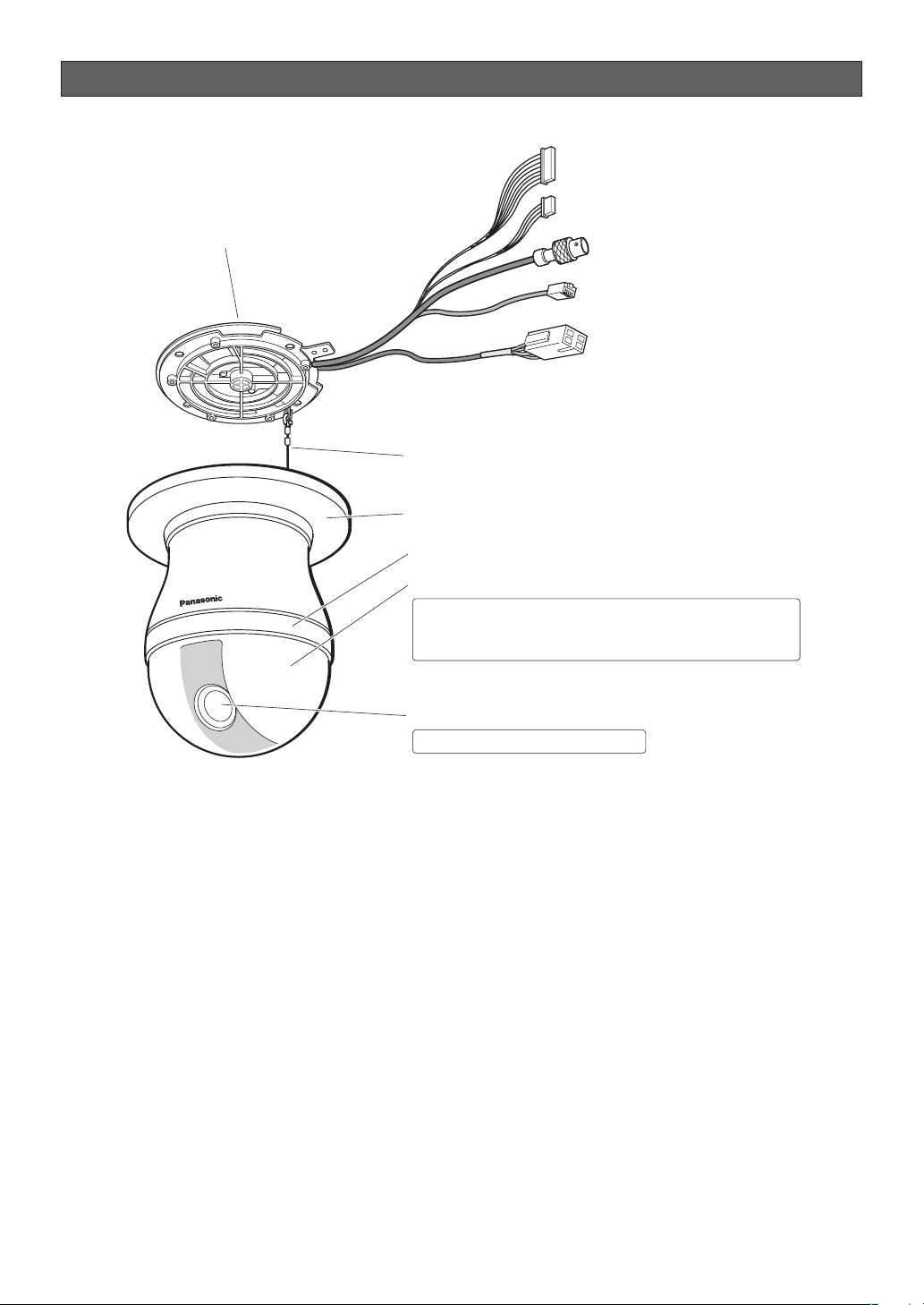
CONSTRUCTION
Alarm Input Connector
Alarm Output Connector
Camera Mounting Base
Video Output Connector
Data Port
Power Connector for Camera
Safety Wire
Decorative Cover (provided)
Dome Anchor Ring
Dome Cover
Rotate the dome anchor ring to the left to remove it.
The dome cover is easily damaged,
and should be handled with care.
Lens
The lens cannot be replaced.
Ensuring Trouble-free Operation
• This camera uses a “slip ring” for transmission of electrical power and signals. A dirty slip ring can cause
deterioration of picture quality during panning and generation of noise.
In order to ensure trouble-free camera operation, make sure that the cleaning function (page 35) is turned on.
• If cleaning the slip ring does not eliminate poor picture quality and noise, it could mean that the slip ring has
reached the end of its service life. Contact a qualified service person or system installer to have it replaced.
-10-
Page 11
INSTALLATION PRECAUTIONS
Warning: Discuss the installation location for the
camera with your retailer, and select a place that is
strong enough for the installation. If you install the
camera on a ceiling or wall, except for accidents
caused by fault in the camera, Panasonic holds
absolutely no responsibility for accidents caused by
the camera falling due to unsuitable installation.
Take sufficient care when installing the camera. If
the installation is not strong enough, be sure to
sufficiently reinforce the location and check that it is
safe.
Warning: Always request installation work from a
qualified service person or system installer. Lack of
technical knowledge creates the risk of fire, electric
shock, personal injury, and material damage.
■ Camera Installation Location
• Install the camera on a ceiling (concrete, etc.) at a
location that is sufficiently strong to support it.
• When installing the camera on a ceiling of
insufficient strength (like a drop ceiling), use the
optionally available WV-Q105 Direct Attachment
Ceiling Mounting Bracket or the WV-Q116
Embedded Ceiling Mount Bracket.
• For ceiling mounting, use the optionally available
WV-Q117 Ceiling Mount Bracket.
• For wall mounting, use the optionally available WVQ118 Wall Mount Bracket.
■ This camera is an indoor camera. It is not
designed for outdoor use.
■ This camera is designed for use in a hanging con-
figuration only. Using it in an upright or inclined
configuration can cause malfunction and shorten
the life of the camera.
■ Install the camera in a horizontal configuration,
with the dome pointed downwards.
■ Never install or use the camera in the following
locations.
• Areas directly exposed to rain and water
• Near a swimming pool or other areas where
chemicals are used
• Food preparation areas and other locations where
there are large amounts of steam vapor and oil, in
flammable atmospheres, other special environments
• Areas where radiation, X-rays, strong electric
waves, or magnetism is generated
• At sea, in coastal areas, or in areas where corrosive
gas is being generated
• Areas outside of the allowable ambient operating
temperature range (-10 °C to +50 °C {14 °F to 122
°F})
• In a motor vehicle, on a boat, or other areas subject
to strong vibration (This camera is not designed for
use in a vehicle.)
• Near an air conditioner outlet, near a door that opens
up to the outdoors, or any other area subjected to
temperature extremes (Such conditions can cause
clouding and condensation formation on the dome
cover.)
■ Wiring the Camera
• If you need to connect a ground, be sure to do it before
you connect the main power plug. Also, when
removing the ground, be sure to disconnect the main
power plug.
• The camera does not have a power switch, so it turns on
as soon as the power cord is plugged into a power outlet.
During the electrical work, configure the power supply to
the camera so it can be turned on and off. A self-cleaning
function is activated (PAN/TILT/ZOOM/FOCUS) when the
camera is turned on.
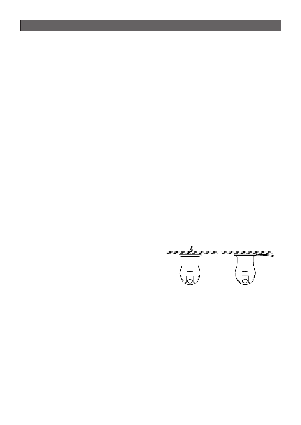
■ When wiring the camera, its cables (power, video
output, RS485, alarm in, alarm out) can exit out
the side or the top of the camera.
• When using the top cable exit configuration, drill a
hole in the ceiling to allow passage of the cables.
(See step 3 on page 15.)
• When using the side cable exit configuration,
prepare the cutout in the die cast case and
decorative cover. (See “Preparing the Camera and
Decorative Cover for Side Cable Exit” on page 15.)
■ Noise interference considerations
When using a power line that is greater than 120 V AC
and wiring that is longer than 1 meter, wiring should be
performed using a separate metal conduit. (The metal
conduit must be earth grounded.)
■ Screws should be ordered separately.
The camera does not come with screws. Make sure
that the materials and structure of the installation
location is strong enough to support the total weight of
the camera.
-11-
Page 12
Important:
• Before setting up the camera for a configuration
where the camera's RS485 data port is used for
camera control (pan, tilt, etc.) by the system
controller, the camera's DIP switches must be
configured to specify the unit number and
communication parameters. (This page)
If DIP switch setting is not performed, the
system controller control will not be possible
and camera setup will have to be performed
again. Be sure to check the DIP switch settings
before setting up the camera.
■ Heat radiation
The surface of the camera radiates heat. Ventilation
holes should be provided when installing the camera in
an enclosed ceiling or confined location where heat
can build up.
Ventilation holes
■ Beware of high humidity.
If the camera is installed when humidity is very high,
moisture may collect in the camera and cause the
dome to become foggy. If the dome becomes foggy,
remove it when the humidity is low and eliminate the
moisture inside the camera, and then replace the
dome. (page 7, 10)
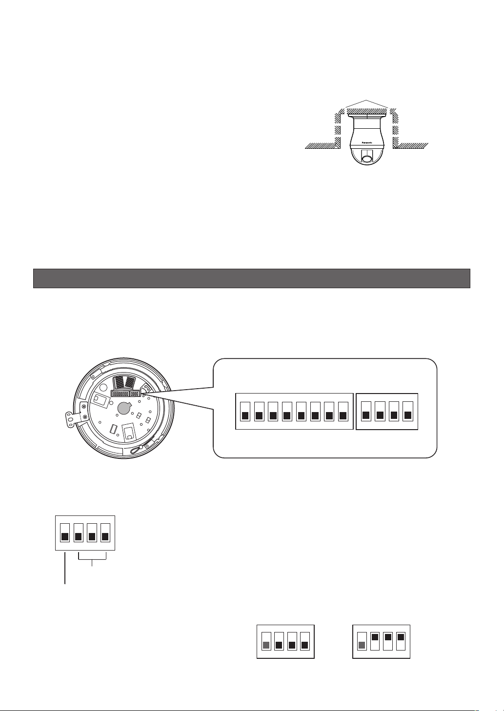
DIP SWITCH SETTINGS
In a configuration where the camera's RS485 data port is used for camera control (pan, tilt, etc.) by the system
controller, the camera's DIP switches must be configured to specify the unit number and communication parameters.
The camera mounting base needs to be removed to access the DIP switches. See steps 1 and 2 on page 15 for
information about how to remove the camera mounting base.
DIP Switch 1
ON
1234
■ Communication Parameters (DIP Switch 2)
The factory default settings of these DIP switches are all OFF.
ON
1234
Communication
Parameters
Terminator
Switch 1: Terminator (Internal Termination Resistance)
Set it to ON in the following situations.
When only one camera is connected.
When only one camera is connected via a daisy chain over a long distance.
Switches 2 through 4: Communication Parameters
This setting toggles between 2-line and 4-line communication.
Use these switches to select the communication protocol
being used.
ON
1234
4-line Communication
-12-
5678
2-line Communication
DIP Switch 2
ON
1234
ON
1234
Page 13
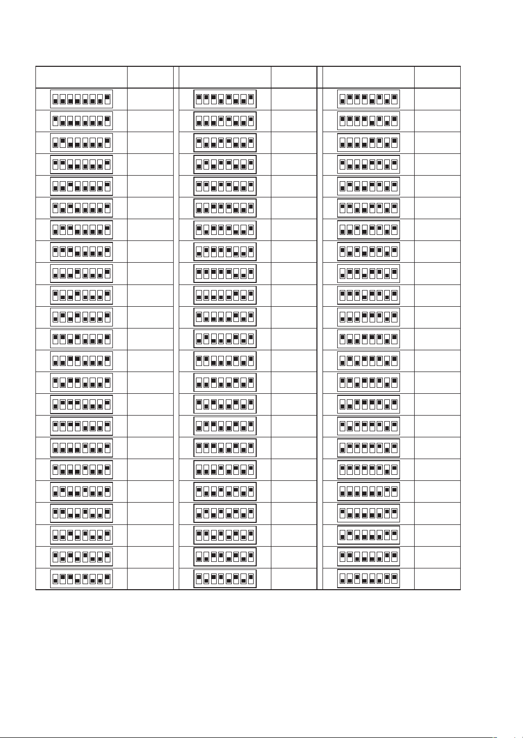
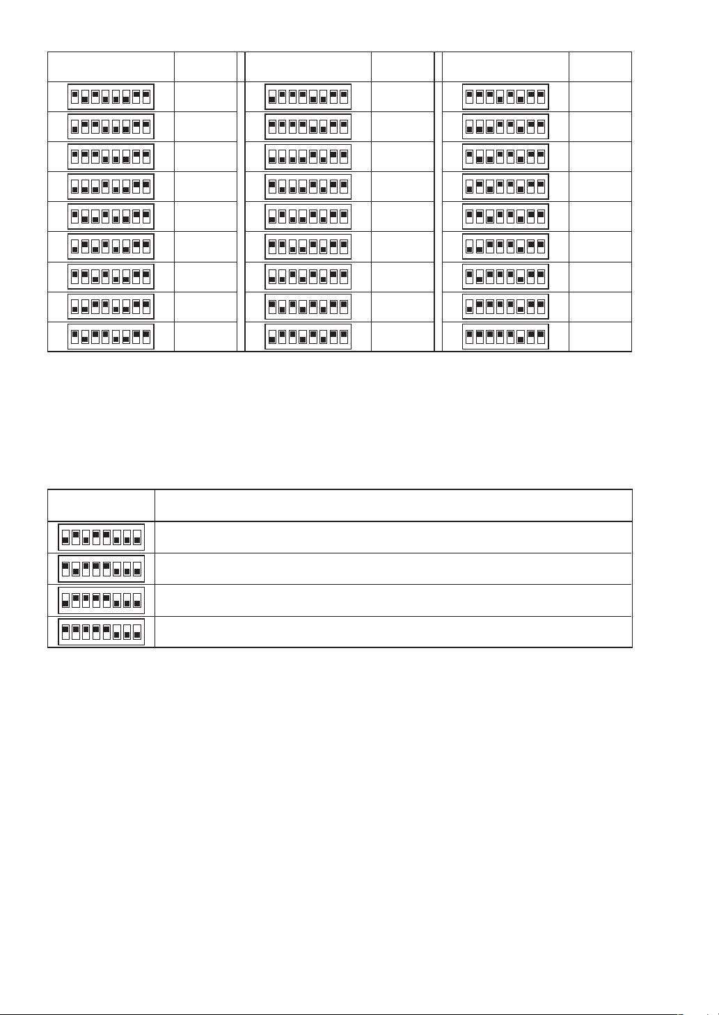
■ Unit Number (DIP Switch 1)
The factory default settings of these DIP switches are all OFF. (Coaxial Multiplex System)
DIP Switch 1
ON
1234
1234
1234
1234
1234
1234
1234
1234
1234
1234
1234
1234
1234
1234
1234
1234
1234
1234
1234
1234
1234
1234
1234
5678
5678
5678
5678
5678
5678
5678
5678
5678
5678
5678
5678
5678
5678
5678
5678
5678
5678
5678
5678
5678
5678
5678
ON
ON
ON
ON
ON
ON
ON
ON
ON
ON
ON
ON
ON
ON
ON
ON
ON
ON
ON
ON
ON
ON
Unit
Number
1 ~ 96 *
1
2
3
4
5
6
7
8
9
10
11
12
13
14
15
16
17
18
19
20
21
22
DIP Switch 1
ON
1234
1234
1234
1234
1234
1234
1234
1234
1234
1234
1234
1234
1234
1234
1234
1234
1234
1234
1234
1234
1234
1234
1234
5678
5678
5678
5678
5678
5678
5678
5678
5678
5678
5678
5678
5678
5678
5678
5678
5678
5678
5678
5678
5678
5678
5678
ON
ON
ON
ON
ON
ON
ON
ON
ON
ON
ON
ON
ON
ON
ON
ON
ON
ON
ON
ON
ON
ON
Unit
Number
23
24
25
26
27
28
29
30
31
32
33
34
35
36
37
38
39
40
41
42
43
44
45
DIP Switch 1
ON
1234
ON
1234
ON
1234
ON
1234
ON
1234
ON
1234
ON
1234
ON
1234
ON
1234
ON
1234
ON
1234
ON
1234
ON
1234
ON
1234
ON
1234
ON
1234
ON
1234
ON
1234
ON
1234
ON
1234
ON
1234
ON
1234
ON
1234
5678
5678
5678
5678
5678
5678
5678
5678
5678
5678
5678
5678
5678
5678
5678
5678
5678
5678
5678
5678
5678
5678
5678
Unit
Number
46
47
48
49
50
51
52
53
54
55
56
57
58
59
60
61
62
63
64
65
66
67
68
-13-
Page 14
DIP Switch 1
ON
1234
1234
1234
1234
1234
1234
1234
1234
1234
5678
5678
5678
5678
5678
5678
5678
5678
5678
ON
ON
ON
ON
ON
ON
ON
ON
Unit
Number
69
70
71
72
73
74
75
76
77
DIP Switch 1
ON
1234
1234
1234
1234
1234
1234
1234
1234
1234
5678
5678
5678
5678
5678
5678
5678
5678
567
ON
ON
ON
ON
ON
ON
ON
ON
8
Unit
Number
78
79
80
81
82
83
84
85
86
DIP Switch 1
ON
5678
1234
ON
5678
1234
ON
5678
1234
ON
5678
1234
ON
5678
1234
ON
1234
1234
1234
1234
5678
5678
5678
5678
ON
ON
ON
Unit
Number
87
88
89
90
91
92
93
94
95
* When using the Unit Number 1 to 96 setting, the unit number setting needs to be configured using the RS485 SET UP menu. For details
about configuring this setting, see step 2 and page 20.
* Turning on power when this setting is selected causes the RS485 SET UP menu to appear during the initialization routine.
■ RS485 Communication Parameters (DIP Switch 1)
Configuring DIP Switch 1 as shown below resets communication parameters to their factory default settings. You can
then change the settings as desired.
DIP Switch 1 Setting Description
ON
1234
ON
1234
ON
1234
ON
ON
1234
5678
5678
5678
5678
This setting resets communication parameters to the factory default settings.
BAUD RATE : 19 200 bit/s, DATA BIT : 8 bit, PARITY CHECK : NONE, STOP BIT : 1 bit
BAUD RATE : 9 600 bit/s, DATA BIT : 8 bit, PARITY CHECK : NONE, STOP BIT : 1 bit
BAUD RATE : 4 800 bit/s, DATA BIT : 8 bit, PARITY CHECK : NONE, STOP BIT : 1 bit
Perform the following steps to use this setting.
(1) Turn off the camera and use DIP Switch 1 to configure RS485 communication parameters as shown above.
(2) Turn on the camera.
This applies the setting you configured in step (1).
(3) Turn off the camera, use DIP Switch 1 to set the unit number (pages 13 and 14), and then turn the camera
back on again.
-14-
Page 15
CAMERA INSTALLATION
■ Preparing the Camera and
Decorative Cover for Side Cable
Exit
The camera and decorative cover should be prepared
as shown below when mounting the camera on a
ceiling or wall with its cables (power, video output,
RS485, alarm in, alarm out) exiting from the side.
The camera mounting base needs to be removed in
order to prepare the camera. See steps 1 and 2 below
for information about how to remove the camera
mounting base.
* Prevent the dome cover from being scratched by
placing it on a soft cloth while you are working.
Preparing the Camera Die Cast Case*
Break it off with
a pair of pliers.
Preparing the Decorative Cover
2. Rotate the camera base unit in the direction
indicated by the arrow and remove it.
15°
Rotate
Pull the camera
mounting base
up to remove it.
3. Using the camera mounting base as a template,
mark the locations of the four mounting holes on the
ceiling.
If you are using the top cable exit configuration,
mark the location of the cable hole on the ceiling
and drill the hole.
Mark here
Cut it off with
a razor knife.
■ Installing the Camera
• Select an installation location that is strong enough
to withstand the total weight of the camera.
Installing the camera at a location that is too weak
can cause it to fall.
• Remove the protection sheet after the installation
work is complete.
• If you are using an optional bracket to install the
camera, install the bracket in accordance with the
instructions that come with it.
1. Remove the fixing screw (M3 × 6) that secures the
camera to the mounting base.
Put the screw in a place where it will not become
lost.
Fixing screw
After loosening
the screw, press
upwards on the
camera and then
remove it.
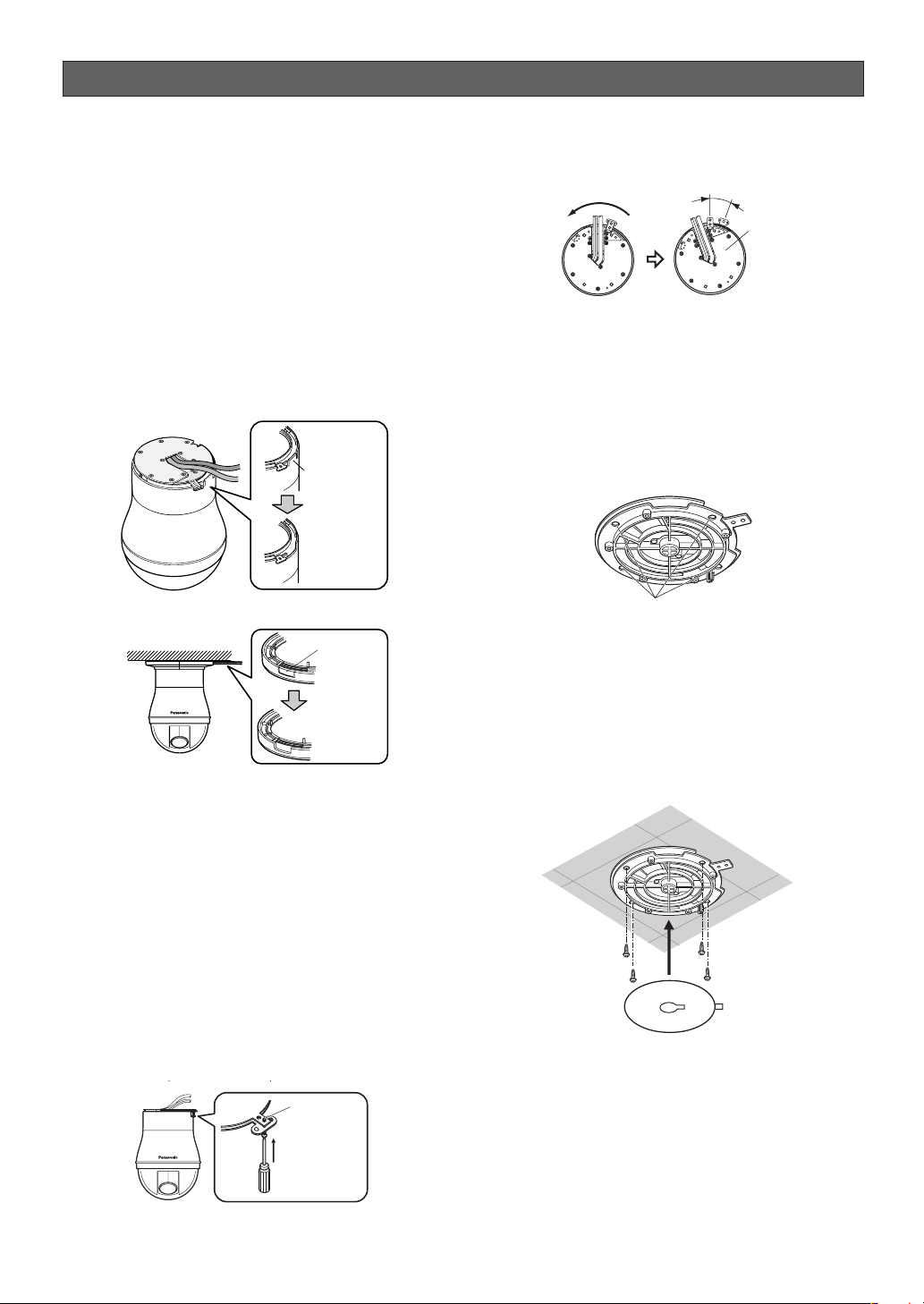
4. Affix the camera mounting base onto the ceiling.
Use screws (M4) at the locations you marked above
to secure the mounting base to the ceiling.
If you do not plan to install the camera right away,
affix the dust protection sheet that comes with the
camera to the mounting base to keep dust off of it.
Screws
(M4, available separately)
Dust Protection Sheet
(comes with camera)
-15-
Page 16
5. Attach the safety wire for securing the camera to
the mounting base.
Pull on the safety wire to make sure its ring is
securely connected to the mounting base hook.
If the dust protection sheet that comes with the
camera is affixed to the mounting base, remove it
before performing the above step.
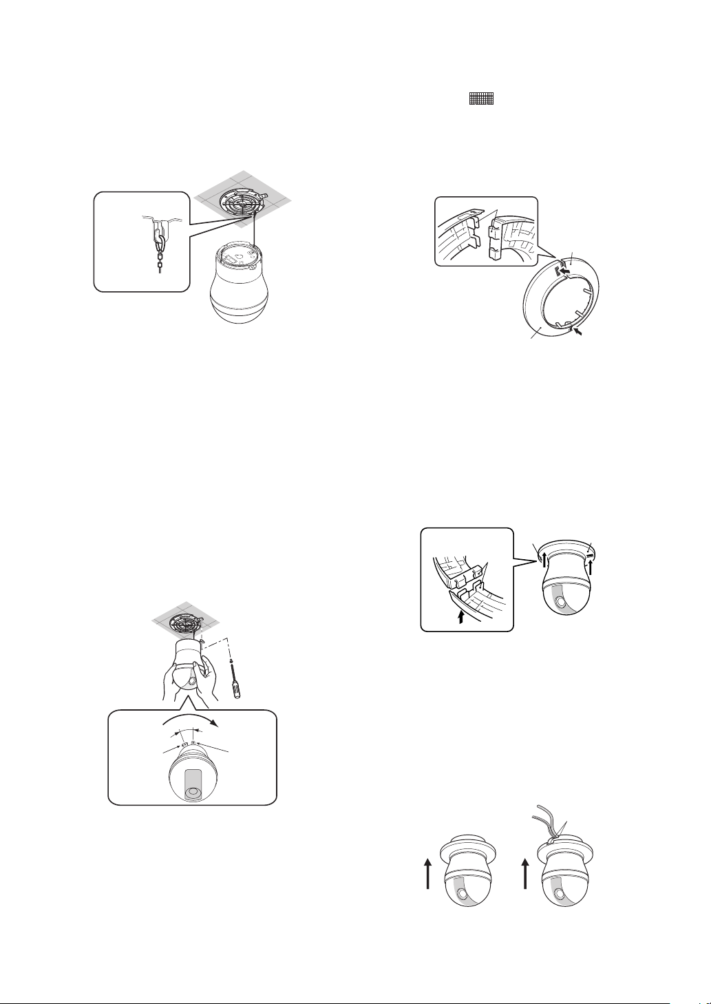
9. Separate the two parts of the decorative cover
(comes with camera).
Press upwards on the decorative cover at the
points marked (indicated by the arrows, in the
illustration below) to unhook the two parts from
each other.
* When removing the decorative cover, the direction
to press ( ) is shown on the side of the decorative
➡
cover.
Safety
wire ring
Note: The safety wire is designed to allow the
camera to hang from it. Do not apply force greater
than the weight of the camera to the wire.
6. Install the camera onto the mounting base.
Aligning with the mounting base, press down on the
camera as far as it will go and rotate in the direction
indicated by the arrow.
7. Use the fixing screw you removed in step 1 to
secure the camera to the mounting base.
8. Check the installation.
• Is the camera is level and installed securely?
• Is the camera free of looseness?
• Does the fixed part of the camera remain in place
when you try to rotate it?
Back
Unhook
Fix securely
Fix securely
Press
Press
Caution: Pressing up on the wrong side of the
decorative cover can damage it.
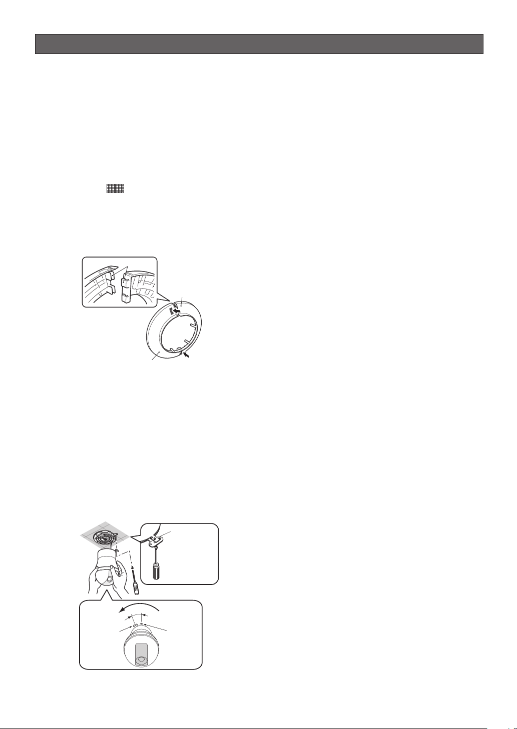
10.Put the two pieces of the decorative cover on the
left and right side of the camera, and hook them
together.
Align the hooks and press the piece indicated by
the arrow in the illustration below into the other
piece.
Hold
securely
Press
Back
Align
hook
Hold
securely
Press
Camera
15°
Rotate
Camera
Mounting
Base
11.Slide the decorative cover up to the ceiling.
• In the case of a top cable exit configuration, slide
the decorative cover straight up and press it firmly
against the ceiling.
• In the case of a side cable exit configuration, align
the cutout in the decorative cover with the cables
as you slide it up, and press it firmly against the
ceiling.
Top Cable Exit
Configuration
Side Cable Exit
Configuration
Align with
cutout
-16-
Page 17
UNINSTALLING THE CAMERA
Caution: Make sure you perform the steps below
carefully and exactly when uninstalling the camera
and decorative cover. Failure to do so creates the
risk of damage to the camera.
■ Removing the Decorative Camera
Note that you need to separate the two parts of the
decorative cover in order to remove it.
1. Unhook the two parts of the decorative cover.
Press upwards on the decorative cover at the
points marked (indicated by the arrows, in the
illustration below) to unhook the two parts from
each other.
* When removing the decorative cover, the direction
to press ( ) is shown on the side of the decorative
cover.
➡
Back
Unhook
Fix securely
Fix securely
Press
Press
■ Uninstalling the Camera
The camera and its base unit are secured by screws.
This configuration provides double anchoring, and you
should use the following procedure to uninstall the
camera.
1. Remove the fixing screw that secures the camera to
the mounting base.
Put the screw in a place where it will not become
lost.
2. Remove the camera from the mounting base.
Rotate the camera in the direction indicated by the
arrow and remove it.
Fixing screw
After loosening
the screw, press
upwards on the
camera and then
remove it.
15°
Rotate
Camera
Camera
Mounting
Base
3. Remove the safety wire from the mounting base.
-17-
Page 18
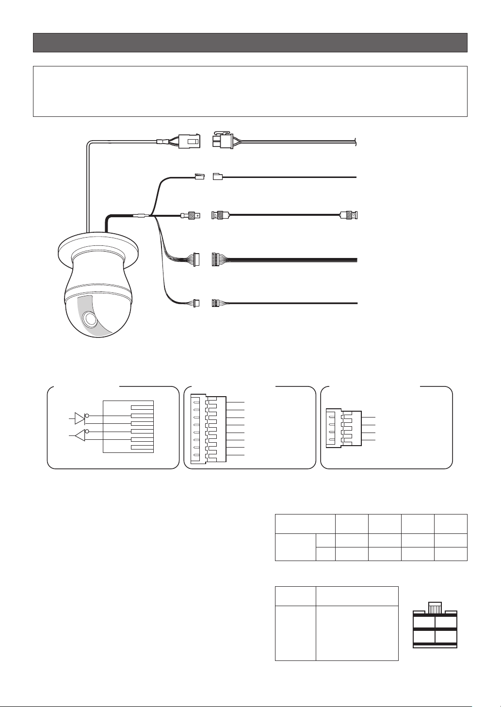
CONNECTIONS
Precautions
• The following connections should be made by qualified service personnel or system installers in accordance
with all local codes.
• See the reverse side of the cover page for main lead connection.
24 V AC 24 V AC Cable for camera
RS485 Data Port
Data
Tx
Data
Rx
Red
Orange
Yellow
Green
RS485 Data Port
(RJ-12)
Twisted Pair Cable*1
To Matrix Switcher,
(RJ-12)
etc.
Video Output
Connector
Coaxial Cable (5C-2V)*2
To VIDEO IN port
(BNC)
(CAMERA IN)
Alarm Input
Connector
8P Alarm Cable (provided)
To sensor, etc.
Alarm Output
Connector
PP Alarm Cable (provided)
To buzzer,
display device, etc.
*1: For twisted pair cable, use shielded low-impedance cable with a thickness of at least AWG#22
*2: Keep the overall length of coaxial cable under 1200 meters (in the case of 5C-2V).
*3: Be sure to connect the grounding cable to ground.
T(B)
T(A)
R(B)
R(A)
2
(0.33 mm
).
Alarm Input Connector
Alarm In 1 (Black)
GND (Brown)
Alarm In 2 (Red)
GND (Orange)
Alarm In 3 (Yellow)
GND (
Light Blue or Green
Alarm In 4 (Blue)
GND (Violet)
Alarm Output Connector
)
Alarm Out 1 (Gray)
GND (White)
Alarm Out 2 (Pink)
GND (Light Green
or Light Blue)
Alarm In/Out Ratings
Alarm In : 5 V DC pull-up input. Drive capacity of at
lease 0.2 mA required.
OFF : 4 V DC minimum 5 V DC maximum,
or open
ON : 1 V DC maximum or short
Alarm Out : Open collector output. 16 V DC, 100 mA
maximum drive capacity
OFF : Open
ON : 100 mA maximum
* When connecting to an external device, set up the
system so the ratings are not exceeded.
Note: Do not turn off camera power within 30 seconds
after turning it on. Doing so can cause pan, tilt, zoom,
or focus to go out of position.
• 24 V AC Power Supply Connection
Recommended wire gauge sizes for 24 V AC line
Copper wire size
(AWG)
Length
of cable
(approx.)
(m)
#24
(0.22mm
20 30 45 75
65 100 160 260
(ft)
2
)
(0.33mm
#22
2
)
(0.52mm2)
Accessory Connector Information
Pin no. Power source
1
24 V AC LIVE
2
24 V AC NEUTRAL
3
Ground
4
Not use
-18-
#20
4
2
#18
(0.83mm2)
3
1
Page 19
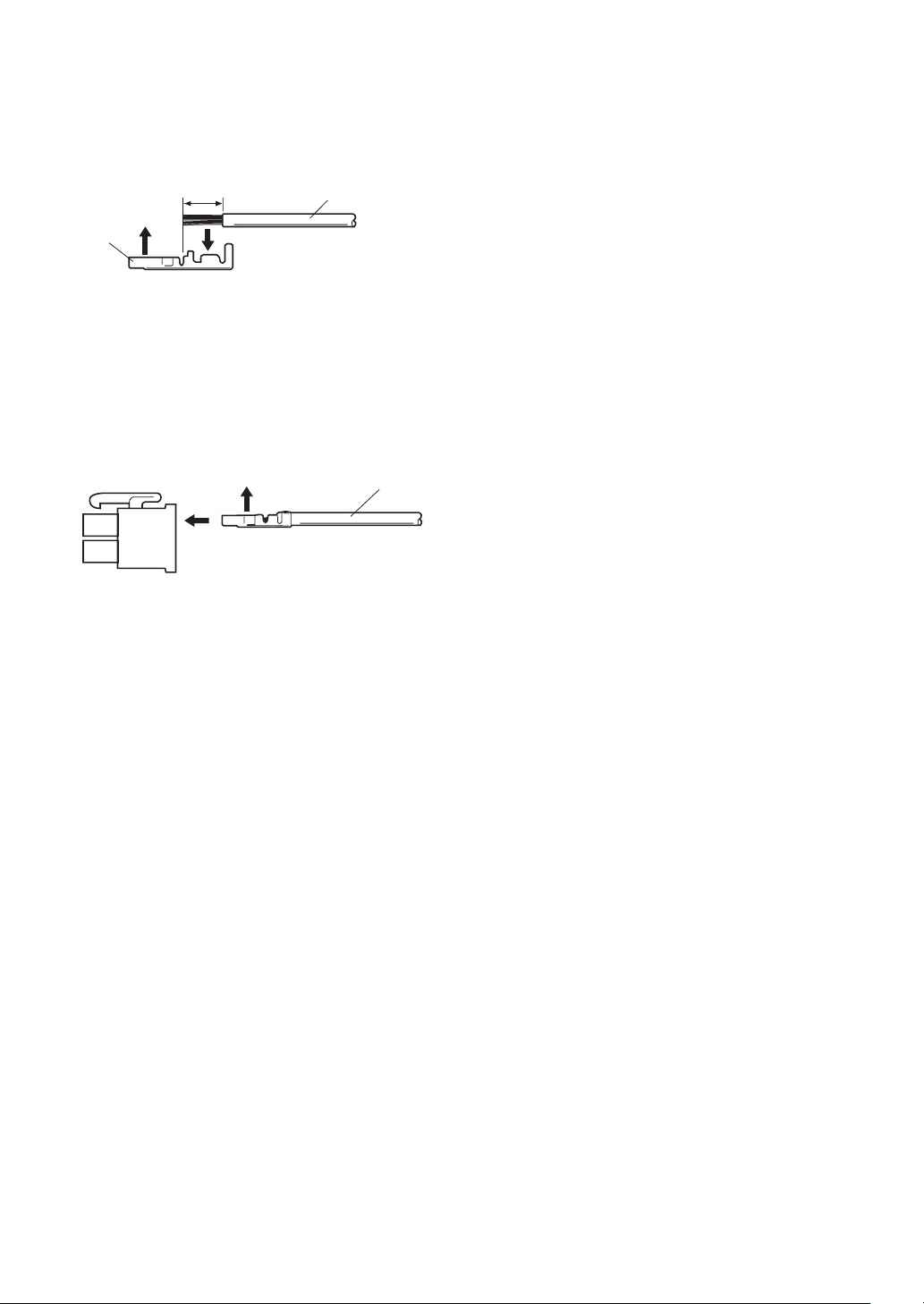
How to Assemble the Cable with the Accessory
Connector
Strip back the cable jacket approx. 3 mm {0.1"} and
separate the individual conductors.
Approx.
Approx.
3 mm {0.1"}
Contact
Contact
Up
Up
3 mm {0.1"}
A
Insert
Insert the wire until A position
Insert the wire until A position
and clamp the contacts.
and clamp the contacts.
Wire
Wire
Prepare the individual conductors for clamping. Use
MOLEX band tool part number 57027-5000 (for ULStyle Cable UL1015) or 57026-5000 (for UL-Style
UL1007) for clamping the contacts.
After clamping the contacts, push them into the proper
holes in the accessory connector of this camera until
they snap in place.
Up
Contact
Wire
Cautions:
• Shrinking the cable-entry seal is a one-time
procedure. Do not shrink the cable-entry seal until
ascertaining that the unit is functioning.
• CONNECT THIS TO 24 V AC CLASS 2 POWER
SUPPLY ONLY.
-19-
Page 20
RS485 SETUP
Use the following procedure to configure the RS485
setup when you want to use the system controller to
control the camera (pan, tilt, etc.) via the camera's data
port.
1. Display the setup menu (page 21), move the cursor
to COMMUNICATION O, and then press the CAM
(SET) button.
This will display the RS485 setup menu.
2. Check the unit number. (page 13)
The UNIT NUMBER item shows the unit number
specified by DIP Switch 1. The factory default unit
number is 1.
If DIP Switch 1 specifies 1 to 96 as the unit number,
move the cursor to UNIT NUMBER and then tilt the
joystick left or right to select a unit number (1 to 96).
** RS485 SETUP **
UNIT NUMBER
SUB ADDRESS
BAUD RATE
DATA BIT
PARITY CHECK
STOP BIT
XON/XOFF
WAIT TIME
ALARM DATA
DELAY TIME
RET TOP
1
----19200
8
NONE
1
NOT USE
OFF
AUTO2
OFF
Note: It is not necessary to configure the RS485
SET UP menu SUB ADDRESS setting.
3. Move the cursor to BAUD RATE, and then tilt the
joystick left or right to select a baud rate setting.
Tilting the joystick cycles through the baud rate
(transmission speed) display in the sequence
shown below. (unit: bits/s) The factory default
setting is 19200.
8. Move the cursor to WAIT TIME, and then tilt the
joystick left or right to select a wait time setting.
The wait time is the time that the camera should
wait before resending data when no receive
acknowledgement (ACK) is returned after data is
sent.
Tilting the joystick cycles through the wait time
display in the sequence shown below. (unit: ms)
The factory default setting is OFF.
OFF ↔ 100MS ↔ 200MS ↔ 400MS ↔ 1000MS
9. Move the cursor to ALARM DATA, and then tilt the
joystick left or right to select an alarm data send
mode setting.
POLLING : Sends alarm data in response to a
request by the system controller.
AUTO1 : Sends alarm data each time an alarm
signal is input.
AUTO2 : Sends alarm data at five-second intervals.
This is the factory default setting.
10.Move the cursor to DELAY TIME, and then tilt the
joystick left or right to select a delay time setting.
The delay time is the time is the time the camera
should wait before sending a receive acknowledge
(ACK). The delay time display changes in the
sequence shown below. (unit: ms) The factory
default setting is OFF.
OFF ↔ 100MS
This setting can be configured only when 2-line
configuration is selected by DIP Switch 2. (page 12)
2400 4800 9600 19200
4. Move the cursor to DATA BIT, and then tilt the
joystick left or right to select a data bit setting (7 or
8).
The factory default setting is 8.
5. Move the cursor to PARITY CHECK, and then tilt the
joystick left or right to select a parity bit setting
(NONE, ODD, EVEN).
The factory default setting is NONE.
6. Move the cursor to STOP BIT, and then tilt the
joystick left or right to select a stop bit setting (1 or
2).
The factory default setting is 1.
7. Move the cursor to XON/XOFF, and then tilt the
joystick left or right to select an XON/XOFF setting.
The factory default setting is NOT USE.
NOT USE: Disables X ON/X OFF data flow control.
USE : Enables X ON/X OFF data flow control.
-20-
Page 21
USING THE SETUP MENU
For details about operations, see the operating
instructions for the equipment you are using.
This manual describe procedures for operating system
controller WV-CU650.
All setting configuration procedures start from the
setup menu. This section explains how to display the
setup menu and provides details about the menu items
that it contains.
■ Displaying the Setup Menu
● When using the WV-CU650
(1) Select the camera you want to set up (this
camera), and the monitor where you want to
display the setup menu.
(2) Press the MENU button to display LCD MENU
CAM 101.
(3) Press the ENTER button or CAM (SET) button to
display CAMERA SETUP.
(4) Press the F1 button.
MODEL WV-CS954
CAMERA
PAN/TILT
ALARM
SPECIAL
COMMUNICATION
SCENE SELECT
LANGUAGE
→QUICK SETUP
PASSWORD LOCK OFF
q
e
t
u
o
w
r
y
i
■ Language Setting
MODEL WV-CS954
CAMERA
PAN/TILT
ALARM
SPECIAL
COMMUNICATION
SCENE SELECT
LANGUAGE
→QUICK SETUP
PASSWORD LOCK OFF
1. Move the cursor to LANGUAGE O, and then press
the CAM (SET) button.
2. On the 8-language selection menu that appears,
select the language you want to use.
* All of the example screens in these Operating
Instructions show English display messages.
3. Move the cursor to SET, and then press the CAM
(SET) button.
When you switch the languages, the password and
titles are deleted.
* If you have selected either Japanese or Chinese as
the language, only the IDs and titles can be set in
katakana or Chinese.
* The “LANGUAGE” display remains in English even
when the language setting is changed.
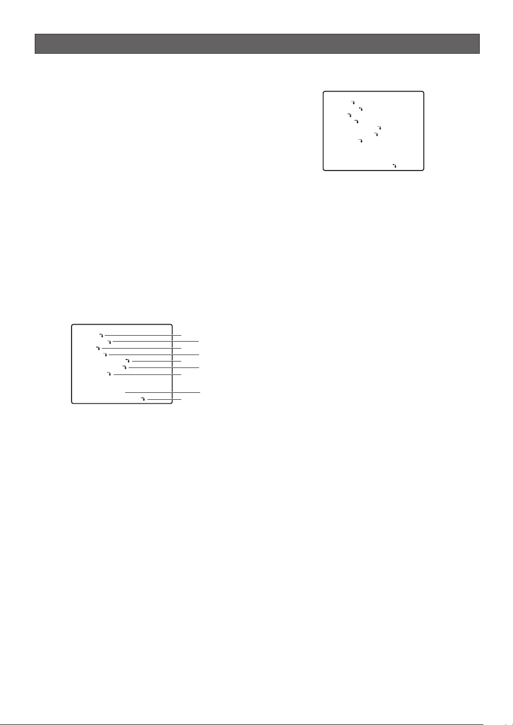
Refer to the pages below for details of setup menu
items.
q CAMERA Camera Settings Page 22
w PAN/TILT Pan and Tilt Page 27
e ALARM Alarm Settings Page 36
r SPECIAL Special Settings Page 39
t COMMUNICATION* Communication Settings
Page 20
y SCENE SELECT Scene Select Settings
Page 40
u LANGUAGE Language Setting
This page
i QUICK SETUP Quick Menu Settings
Page 41
o PASSWORD LOCK Password Settings
Page 42
* This item appears only when RS485 settings are
configured with the DIP switches.
-21-
Page 22
CAMERA SETTINGS
■ Using the Camera Setup Menu
Display the camera setup menu from the setup
menu to configure camera settings. First, display
the camera setup menu.
1. Display the setup menu (page 21), move the cursor to
CAMERA O, and then press the CAM (SET) button.
This will display the camera setup menu.
**CAMERA SETUP** 1/2
CAMERA ID OFF
ALC/MANUAL ALC
SHUTTER AUTO
AGC ON(MID)
SENS UP OFF
SYNC INT
WHITE BAL ATW1
DNR LOW
RESOLUTION HIGH
BW MODE
AF MODE AUTO L
**CAMERA SETUP** 2/2
ZOOM LIMIT ×30
STABILIZER OFF
RET TOP
* The following sections numbered q to !3 explain
how to use each of the camera setup menu items.
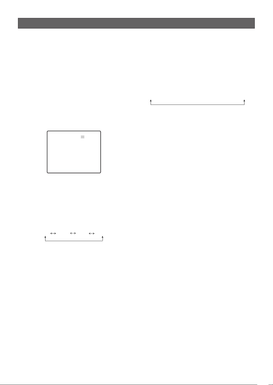
(1) Camera ID (CAMERA ID)
The camera ID is a series of alphanumeric
characters that indicate the location of the camera.
This item can be used to turn display of the camera
ID on the monitor screen on or off, and to input the
camera ID.
1. Move the cursor to CAMERA ID, and then tilt the
joystick left or right to toggle camera ID display on
and off.
2. Select ON or OFF, and then press the CAM (SET)
button.
3. Use the joystick to move the cursor the character
you want to input, and then press the CAM (SET)
button.
This will cause the selected character to appear in
the camera ID input area. Repeat step 3 as many
times as necessary to input all of the characters for
the camera ID. (Example: DOOR)
To input a blank space
Move the cursor to SPACE, and then press the
CAM (SET) button.
To delete previously input characters
Move the cursor to RESET, and then press the CAM
(SET) button.
To change previously input characters
Use the joystick to move the cursor to the camera
ID input area. Next, tilt the joystick left and right to
move the ↑ pointer to the character you want to
change. Finally, use step 3 above to input the new
character.
q
e
t
u
o
!1
!2
w
r
y
i
!0
!3
CAMERA ID-- 0123456789
ABCDEFGHIJKLM
NOPQRSTUVWXYZ
().,'":;&#!?=
+-*/%$
SPACE
---- POSI RET RESET
DOOR............
Camera ID Input area
4. Move the cursor to POSI, and then press the CAM
(SET) button.
This will display the ID position setting menu.
5. Use the joystick to select a camera ID display
position, and then press the MON (ESC) button.
This registers the camera ID display position and
returns to the camera setting menu.
DOOR
(2) Light Control (ALC/MANUAL)
1. Move the cursor to ALC/MANUAL, and then tilt the
joystick left or right to toggle between ALC and
MANUAL.
ALC : Enables automatic lens iris adjustment in
accordance with subject brightness.
Select this ALC when using SUPER-D 3.
MANUAL: Adjust the lens iris with the IRIS button on
the system controller. Fixes the lens iris.
Note: The backlight compensation submenu
associated with this menu is described separately
and should be set up after installing the camera at
the site and observing the actual site picture.
2. If ALC is set in step 1, press the CAM (SET) button
to set SUPER-D 3.
SUPER-D 33(Super Dynamic 33)
When there is wide variation between the illumination of
light and dark areas of the location being monitored,
the camera adjusts the lens iris in accordance with the
bright areas. This causes loss of detail in dark areas.
Conversely, adjusting lens brightness for the dark
areas cause brighter area to become washed out.
SUPER-D 3 digitally combines an image that is set up
for a clear view of bright areas with an image that is set
up for a clear view of dark areas, creating a final image
that preserves overall detail.
-22-
Page 23
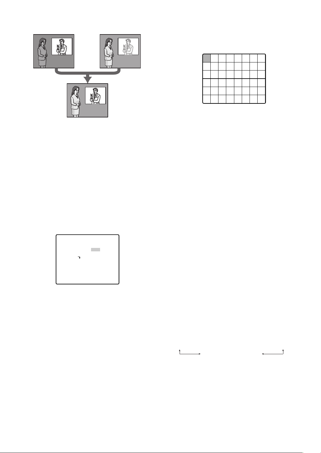
Loss of detail
in dark areas...
Wash out of
bright areas ...
Tw o images
digitally combined
to create a clear
final image
Notes:
• SUPER-D 3 is supported only when ALC is
selected for light control (ALC/MANUAL).
• Camera settings are limited to the following when
SUPER-D 3 is turned on.
SHUTTER: OFF, AUTO (This page)
SENS UP : OFF, AUTO (page 24)
• If lighting conditions cause either of the following
phenomena, turn off SUPER-D 3.
(1) Screen flickering or abnormal color
(2) Digital noise in the bright areas of the screen
3. Move the cursor to SUPER-D3, and then tilt the
joystick left or right to toggle between on and off.
ON : Turns on SUPER-D 3. (Go to Step 6)
OFF : Turns off SUPER-D 3. (Go to Step 4)
**ALC CONT**
BACK LIGHT COMP
SUPER-D3
MASK SET
LEVEL
OFF
••••I••••
- +
and left switches simultaneously.
(3) After masking all of the cells you want, press the
MON (ESC) button to return to the ALC CONT
menu in step 1.
6. Move the cursor to LEVEL, and then tilt the joystick
left and right to adjust the picture output level
(picture contrast).
If you selected ON in step 3 of this procedure, best
results can be obtained by setting a contrast level
that is somewhat high. A contrast level that is too
high, however, may increase the tendency of
afterimages and noise.
Note:
• If operation of the system controller's IRIS
(OPEN, CLOSE) button during operation is done
after the menu is closed, the LEVEL on the
CAMERA menu is reflected and stored for these
settings. However, if the camera is in a preset
position, it is reflected as a parameter of the
preset position. To return to the initial factory
default level, execute the system controller's iris
reset.
• When the Light Control is in ALC, "IRIS-CLOSE"
is displayed below the pan/tilt/zoom position
display when the iris is completely closed.
When the Light Control is in MANUAL, "IRISCLOSE" is not displayed.
RET TOP
4. Move the cursor to MASK SET O, and then press
the CAM (SET) button.
This will display the mask area screen, with the
cursor in the upper left cell.
5. Mask the cells in the area where background
lighting is bright. Masking an area will cause its
brightness level to be ignored.
Use the following steps to perform masking
(1) Tilt the joystick up and down, and left and right
to move the cursor to a cell you want to mask.
(2) Press the CAM (SET) button to mask the cell.
Moving the cursor to a cell that is already
masked causes the blinking pattern of the
cursor to alternate between horizontal stripes
and white.
Pressing the CAM (SET) button while the cursor
is located at a masked cell cancels the masking
of the cell.
To cancel all masking areas, press the F2 button
of WV-CU550C. For WV-RM70, press the right
(3) Shutter Speed (SHUTTER)
1. Move the cursor to SHUTTER, and then tilt the
joystick left or right to select a shutter speed
setting.
Tilting the joystick cycles through the shutter speed
settings display in the sequence shown below.
(unit: sec)
When SUPER-D 33is turned off
OFF ↔ AUTO ↔ 1/100 ↔ 1/250 ↔ 1/500 ↔ 1/1000
1/10000 ↔ 1/4000 ↔ 1/2000
When SUPER-D 33is turned on
OFF ↔ AUTO
AUTO: This setting, by moving the shutter
automatically when necessary, provides a
clearer picture of extremely bright objects
outdoors, etc.
OFF : Fixed at 1/60 seconds.
-23-
Page 24

Notes:
• When AUTO is selected for the shutter setting,
fluorescent lighting may cause flickering of the
picture. If this happens, select OFF or 1/100 for
the shutter speed setting.
• AUTO is disabled when MANUAL is selected for
light control (ALC/MANUAL) and FIX is selected
for electronic sensitivity enhancement (SENS UP).
(4) Gain Control (AGC)
1. Move the cursor to AGC, and then tilt the joystick
left or right to select a gain control setting.
ON (LOW) : Low gain
ON (MID) : Medium gain
ON (HIGH) : High gain
OFF : Fixed gain
Note: When AGC is turned on, the noise reduction
function automatically activates under low illumination
to reduce digital noise. This also, however, can cause
afterimages to be generated by moving objects, and
by panning and tilting the camera. For more
information, see the DNR setting (page 25).
(5) Electronic Sensitivity Enhancement (SENS UP)
1. Move the cursor to SENS UP, and then tilt the
joystick left or right to select an electronic sensitivity
enhancement setting.
The electronic sensitivity enhancement setting can
be changed only when OFF or AUTO is selected for
the shutter speed (SHUTTER) setting. Tilting the
joystick cycles through the settings display in the
sequence shown below.
When SUPER-D 33is turned off
OFF ↔ X2 AUTO ↔ X4 AUTO ↔ X6 AUTO ↔ X10 AUTO ↔ X16 AUTO
↔↔
X32 FIX X32 AUTO
X16 FIX ↔ X10 FIX ↔ X6 FIX ↔ X4 FIX ↔ X2 FIX ↔ OFF
When SUPER-D 33is turned on
OFF ↔ X2 AUTO ↔ X4 AUTO ↔ X6 AUTO
X32 AUTO ↔ X16 AUTO ↔ X10 AUTO
Note: The following are the differences between
AUTO and FIX.
AUTO: Selecting X32 AUTO, for example,
automatically increases sensitivity, up to
a maximum of 32 times.
FIX :Selecting X32 FIX, for example,
increases sensitivity 32 times.
The FIX settings cannot be selected when the
shutter speed (SHUTTER) setting is 1/100.
Caution: Turning on SENS UP can cause digital noise
and white spots (blemish) to appear in the picture.
(6) Synchronization (SYNC)
This camera supports the following three sync modes,
which are listed in priority sequence from highest
priority to lowest.
(1) Multiplexed vertical drive (VD2)
(2) Internal sync (INT)
(3) Line-lock (LL)
Input of a multiplexed vertical driver (VD2) signal
automatically switches to VD2 sync, regardless of the
camera's current sync mode (SYNC). In this case, the
camera setting menu shows EXT (VD2) for the SYNC
setting, which cannot be changed to internal sync
(INT) or line-lock (LL).
The following procedures explain how to select internal
sync (INT) and line-lock sync (LL), and how to perform
phase adjustment when line-lock sync (LL) is selected.
1. Move the cursor to SYNC, and then tilt the joystick
left or right to select the sync mode.
INT :Internal sync
LL : Line-lock (Cannot be used in areas with 50 Hz
power.)
Selecting LL and pressing the CAM (SET) button
will display the SYNC setting menu, which can be
used for configuring detailed settings. (This page)
● Adjusting the Phase for Line-lock
Synchronization
Connect the video output signal of the camera being
adjusted and the reference video output signal to a
two-input oscilloscope.
Set the oscilloscope to the vertical rate, and then
expand the vertical sync portion on the oscilloscope.
1. Move the cursor to COARSE, and then tilt the
joystick left or right to align the coarse adjustment
of the vertical phases of the camera being adjusted
with that of the reference camera.
Coarse adjustment be performed across 16 steps
(1 through 16). Adjusting past step 16 returns to
step 1.
↔↔
2. Move the cursor to FINE, and then tilt the joystick
left or right to align the fine adjustment of the
vertical phases of the camera being adjusted with
that of the reference camera.
Notes:
• To reset COARSE and FINE to the preset values,
press the F2 button. For WV-RM70, press the
right and left switches simultaneously. COARSE
is preset to zero-crossing of the AC line phase.
• If the AC line phase contains spike noise, etc.,
the vertical phase of the video output signal may
be disturbed.
-24-
** SYNC **
V PHASE
COARSE
FINE
RET TOP
1(1--16)
••••I••••
- +
Page 25

(7) White Balance (WHITE BAL)
1. Move the cursor to WHITE BAL, and then tilt the
joystick left or right to select a white balance mode.
(1) Auto-Tracing White Balance Mode (ATW1/ATW2)
In this mode, the camera continually monitors
the color temperature of the light source and
automatically adjusts white balance.
The following are the approximate supported
color temperature ranges in this mode.
ATW1: 2,700 K to 6,000 K
ATW2: 2,000 K to 6,000 K (Mode recommended
for sodium lighting)
Proper white balance may not be possible under
the following conditions. In such cases, use the
AWC while balance mode.
• When the subject contains mostly dark colors
• When the light source is a deep blue sky or
twilight
• When illumination of the subject is low
(2) Auto-Tracing White Balance Control (AWC)
In this mode, the supported color temperature
range is approximately 2,000 K to 10,000 K. This
mode is best in locations where the light source
is constant.
(a) To select AWC, tilt the joystick left and select
AWC→PUSH SET.
(b) Press the CAM (SET) button to start white
balance adjustment. PUSH SET is highlighted
on the display while white balance adjustment is
being performed.
• PUSH SET becomes unhighlighted again when
white balance adjustment is complete. Tilt the
joystick right to display AWC.
• If white balance adjustment cannot be completed
for some reason, PUSH SET will remain
highlighted on the display. If this happens, it could
mean that the color temperature is outside the
supported range, or that illumination is too low.
2. Select ATW1, ATW2, and AWC, then press the CAM
(SET) button, either the ATW setting menu or the
AWC setting menu appears, and you can fine tune
the white balance.
Move the cursor to R or B, and then tilt the joystick left
or right to fine tune the level. The R is red and the B is
blue, moving in the + direction makes the colors
darker, moving in the - direction makes them lighter.
** ATW1 **
R
B
RET TOP
••••I••••
- +
••••I••••
- +
Note: White balance is adjusted in accordance with
on-screen color temperature, which the camera
detects automatically. Correct adjustment may not
be possible if a strong light source is shining on the
screen.
(8) Digital Noise Reduction (DNR)
1. Move the cursor to DNR, and then tilt the joystick
left or right to select a digital noise reduction (DNR)
setting.
LOW : Low DNR, Low afterimage
HIGH : High DNR, High afterimage
(9) Resolution (RESOLUTION)
1. Move the cursor to RESOLUTION, and then tilt the
joystick left or right to select NORMAL or HIGH.
NORMAL: Sets horizontal resolution to a minimum
of 480 lines. (In color mode)
HIGH : Sets horizontal resolution to a minimum
of 520 lines. (In color mode)
(10) Black and White Mode (BW MODE)
Moving the cursor to BW MODE and pressing the CAM
(SET) button displays a BW MODE setting menu.
Use the BW MODE setting menu to configure black
and white mode settings.
1. Move the cursor to BW, and then tilt the joystick left
or right to select a black and white control setting.
AUTO : The camera automatically switches
between the color mode and the black and
white mode in accordance with picture
brightness (illuminance).
The black and white mode is selected
when lighting is low, while the color mode is
selected for bright lighting.
ON : Selects the black and white mode.
OFF : Selects the color mode.
** BW MODE **
BW
LEVEL
DURATION TIME
BURST(BW)
RET TOP
AUTO
HIGH
•I••
S L
ON
Note: The above setting cannot be configured
when BW is selected for the ALARM IN 4 setting
(page 38).
2. If you selected AUTO in step 1, move the cursor to
LEVEL and then tilt the joystick left to select the
threshold illuminance level for switching between
the color mode and the black and white mode.
The illuminance shown below is based on the
assumption that the camera is used in an area lit by
halogen lamps, and that AGC on the menu is set to
MID.
LOW : Switches to the black and white mode when
illuminance around the camera is
approximately 1.5 lux{fc} or lower (when
AGC ON (MID), SENS UP OFF is set).
HIGH : Switches to the black and white mode when
illuminance around the camera is
approximately 3 lux{fc} or lower (when AGC
ON (MID), SENS UP OFF is set).
-25-
Page 26

Note: When near-infrared lamps are used, the
image may be displayed out of focus and mode
switching may not perform automatically.
3. If you selected AUTO in step 1, move the cursor to
DURATION TIME and then tilt the joystick left to
select the time the camera should wait before
switching between the color mode and the black
and white mode after there is a change in the
illuminance level.
Available Settings: 10 s - 30 s - 60 s - 300 s
(S) (L)
Note: When AUTO is selected, switching between
the color mode and the black and white mode is not
performed while pan, tilt, zoom, or focus is being
performed.
4. Move the cursor to BURST (BW), and then tilt the
joystick left or right to turn burst signal output on or
off.
This setting is for black and white mode display.
ON: Turns on burst signal output.
OFF: Turns off burst signal output.
Note: With some monitors and VCR models, output
of a camera images in the black and white mode
will not display a proper image unless a burst signal
is provided. Select ON for this setting when using
equipment that requires a burst signal.
(11) Auto Focus (AF MODE)
1. Move the cursor to AF MODE, and then tilt the
joystick left or right to select an auto-focus mode
setting.
MANUAL S.M.L : Activates auto-focus when the AF
button on the system controller is
pressed.
AUTO S.M.L : Auto focus is used automatically
when PAN, TILT or ZOOM are
used in manual operation.
The letters S (Small), M (Medium), and L (Large)
indicate the size of the auto-focus sensing area.
Notes:
• The AUTO (S.M.L.) setting can be selected only
when OFF, x2 FIX or x2 AUTO is selected for the
electronic sensitivity enhancement (SENS UP).
Any other SENS UP setting causes MANUAL
(S.M.L.) to be selected automatically for the
auto-focus mode (AUTO AF).
• Zooming up from WIDE can cause the image to
go out of focus.
• Auto-focus may not be possible with the types of
objects listed below. For such objects, focus
manually.
Example:
• Shiny or high intensity objects
• Objects shot through wet or dirty glass
• Pictures that are a mixture of distant and nearby
objects
• White walls and other single-color objects
• Venetian blinds and other vertically striped
objects
• Slanted objects
• Objects illuminated with low lighting
Auto-focus focuses on the object in the center of
the picture, so objects around the outside periphery
of the picture will not be in focus.
(12) Zoom Limit (ZOOM LIMIT)
1. Move the cursor to ZOOM LIMIT, and then tilt the
joystick left or right to select a zoom limit setting.
When doing manual operation, zoom operation
cannot go beyond the zoom limit.
Optical zoom ranges from 1 to 30 magnifications,
while digital zoom is used for higher magnifications
(up to 300).
Note:
• If zoom limit is set to more than 30x, then zoom
operation pauses at 30x magnification.
• Increasing the zoom to over 30x magnification
(digital zoom) decreases the resolution.
• You cannot set a zoom magnification of greater
than 30x as a preset position.
(13) Auto Image Stabilizer (STABILIZER)
This function electronically compensates for an
unstable camera image due to movement of a
mounting pole or bracket.
1. Move the cursor to STABILIZER, and then tilt the
joystick left or right to turn the stabilizer on or off.
The default setting is OFF
ON : Automatically compensates for an unstable
image.
OFF : Image stabilizer will not operate.
Notes:
• The stabilizer may not be effective for the
following subjects.
Example: • Objects illuminated with low lighting
• Single-color objects (white walls etc)
• Fast moving periodic action, such as
mechanical vibration, may not be tracked.
• The stabilizer does not work during
PAN/TILT/ZOOM/FOCUS or when the camera
setup menu is open.
• When set to ON, some effective pixels on the
edge of the CCD are used by the stabilization
function. This may result in a small reduction in
resolution and a narrower angle of view. After
activating the image stabilizer function, check
that the field of view is correct.
• Image stabilization may not function where there
is excessive camera movement or when the
scene is low light or low contrast objects.
-26-
Page 27
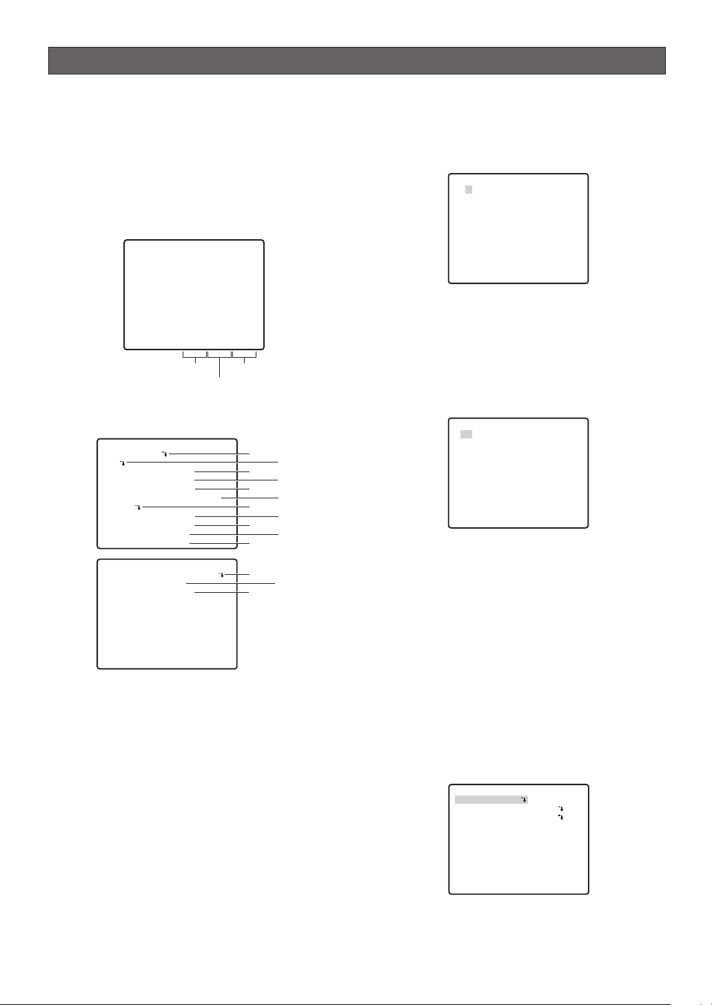
PAN / TILT
■ Using the Pan/Tilt Setup Menu
Display the pan/tilt setup menu from the setup menu to
configure pan and tilt settings.
First, display the pan/tilt setup menu.
Use a shortcut (page 45) to switch between displaying or
not displaying the pan, tilt, and zoom positions (during
pan, tilt and zoom operation) on the monitor screen.
* The tilt position is displayed ranging from -5˚ to 90˚
to -5˚.
360°/ 90°/X001
Pan position
1. Display the setup menu (page 21), move the cursor to
PAN/TILT O, and then press the CAM (SET) button.
This will display the pan/tilt setup menu.
**PAN/TILT SETUP**1/2
PRESET 1
MAP
HOME POSITION OFF
SELF RETURN OFF
AUTO MODE OFF
AUTOPAN KEY AUTO PAN
PATROL
PRIVACY ZONE OFF
IMAGE HOLD OFF
DIGITAL FLIP ON
PROPO.P/T ON
**PAN/TILT SETUP**2/2
AREA TITLE ON(USER)
TILT ANGLE 0°
CLEANING OFF
RET TOP
* The following sections numbered q to !4 explain
how to use each of the pan/tilt setup menu items.
(1) Position Number Selection (PRESET)
Positions can be assigned numbers, each of which can
be configured with a monitoring position and
monitoring conditions.
You can use either the PRESET item or the MAP item on
the pan/tilt setup menu to select a position number.
Position numbers 1 through 4 are used for alarm
functions (pages 37 and 38) and operating them.
1. Move the cursor to the 1 next to the PRESET item,
and then tilt the joystick left or right to change the
position number to the one you want.
2. Press the CAM (SET) button.
This registers the position number setting and
displays the preset setting menu. (this page)
Zoom ratio
Tilt position*
q
e
t
u
o
!1
!2
!4
w
r
y
i
!0
!3
(2) Position Number Selection (MAP)
You could use the MAP item on the pan/tilt setup menu
instead of the PRESET item to select a position number.
1. Move the cursor to MAP O, and then press the
CAM (SET) button.
**PRESET POSITION**
2
1*
6
5
10
9
14
13
18
17
22
21
26
25
30
29
ID:DOOR
033-064 225-256
RET TOP
3
7
11
15
19
23
27
31
4
8
12
16
20
24
28
32
2. Move the cursor to the number you want to select,
and then press the CAM (SET) button.
This registers the position number setting and
displays the preset setting menu. (this page)
To select a position number in the range of 033 to
064, move the cursor to 33-64 in the lower left corner
of the menu, and then press the CAM (SET) button.
Preset numbers set subsequently are the same.
**PRESET POSITION**
34
33
38
37
42
41
46
45
50
49
54
53
58
57
62
61
ID:
065-096 001-032
RET TOP
35
39
43
47
51
55
59
63
36
40
44
48
52
56
60
64
Notes:
• An asterisk (*) to the right of a position number
indicates that it already has a preset position
assigned to it.
The home position number is indicated by the
letter H next to the asterisk.
• When the cursor is located at a position number
that has a position ID, the position ID text
appears next to ID: on the menu screen.
● Position Setting (POSITION SET)
The position setting can be used to specify the camera
position (pan and tilt), the lens zoom setting, and the
focus setting.
1.
Move the cursor to POSITION SET O and press the
CAM (SET) button to display the position setting menu.
PRESET NO. 1*
POSITION SET
PRESET ID
ALC/MANUAL
AF MODE
DWELL TIME
SCENE FILE
PRESET SPEED
RET TOP DEL
2. Move the cursor to →PUSH SET to the right of
PAN/TILT, and then press the CAM (SET) button to
display the PAN/TILT setting menu.
ON
ALC
MANUAL L
10S
OFF
••••••••I
L H
-27-
Page 28
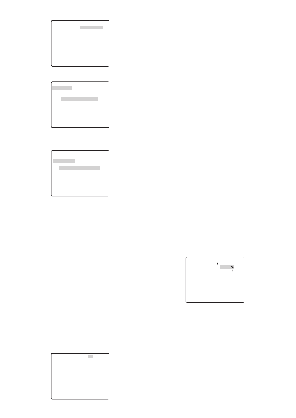
** POSITION 1 **
PAN/TILT
ZOOM/FOCUS
PAN OFFSET SET ← 0
RET TOP
FLOOR1
DOOR
→PUSH SET
→PUSH SET
→
3. Use the joystick to position the camera, and then
press the CAM (SET) button.
** POSITION 1 **
PAN/TILT
ZOOM/FOCUS
U TILT D/L PAN R
PAN OFFSET SET ←
RET TOP
FLOOR1
DOOR
→
PUSH SET
→
PUSH SET
0
→
4. Move the cursor to → PUSH SET to the right of
ZOOM/FOCUS, and then press the CAM (SET)
button to display the ZOOM/FOCUS setting menu.
** POSITION 1 **
PAN/TILT
ZOOM/FOCUS
U ZOOM D/L FOCUS R
PAN OFFSET SET ←
RET TOP
FLOOR1
DOOR
→
PUSH SET
→
PUSH SET
0
→
5. Move the joystick left, right, up and down to adjust
the position of the lens focus, and then press the
CAM (SET) button.
Notes:
• Focusing may be difficult when the camera is at
an angle that is close to horizontal.
•A different position number can be selected by
moving the cursor to the position number at the
top of the position setting menu and tilting the
joystick left and right. Pressing the CAM (SET)
button will change to the setting screen for the
newly selected position number.
• The currently registered camera ID and preset ID
appear at the bottom of the position setting menu.
•
When using a system device other than the WVCU650/CU950*, WJ-HD309A/HD316A over 65
position numbers cannot be set. (as of February 2005)
* Operation procedure may vary depending on
the version of the system controller's software.
For Ver.1.xx or earlier: only camera function
operations are supported
For Ver.2.xx or later: PRESET/PGM PRESET
button is also supported
Align the cursor here
** POSITION 1* **
PAN/TILT
ZOOM/FOCUS
PAN OFFSET SET ← 0
RET TOP
FLOOR1
DOOR
→PUSH SET
→
PUSH SET
→
● Adjusting Camera Position When
Changing Cameras (PAN OFFSET SET)
The system controller etc. has a function for
downloading (saving) and uploading (recovering)
setting information for the camera. This function allows
you to upload (recover) original setting information that
has been downloaded (saved) before some
unforeseen damage or malfunction causes setting
information in the camera to be lost. However, there
may be some slight differences in images from those
uploaded (recovered) when the camera is changed.
The "PAN OFFSET SET" function is for adjusting these
differences.
1. Align the cursor with "PAN OFFSET SET" with the ←
or → arrow, and press the CAM (SET) button to set
the offset value.
Set the offset value to 0.0, or in a range of -10 to
+10. All preset positions for the camera's position
are adjusted according to the offset value.
Important: Data is not compatible with existing
cameras. Uploading setting information from
existing cameras will damage data in the camera. If
data in the camera is damaged, download camera
setting information from a camera that still has the
factory settings and then upload it to the camera
with the damaged data.
● Preset ID Setting (PRESET ID)
The preset ID is a series of alphanumeric characters
that indicate the location of the camera. This item can
be used to turn display of the preset ID on the monitor
screen on or off, and to input the preset ID.
1. Move the cursor to PRESET ID, and then tilt the
joystick left or right to toggle preset ID display on
and off.
PRESET NO. 1*
POSITION SET
PRESET ID
ALC/MANUAL
AF MODE
DWELL TIME
SCENE FILE
PRESET SPEED
RET TOP DEL
2. Select ON or OFF, and then press the CAM (SET)
button.
This will display the preset ID setting menu.
3. Use the joystick to move the cursor the character you
want to input, and then press the CAM (SET) button.
The text input procedure is the same as that for
camera ID input.
See steps 3 through 5 under “(1) Camera ID
(CAMERA ID)” on page 22 for information about
inputting the text for the preset ID and specifying its
position on the display.
-28-
ON
ALC
MANUAL L
10S
OFF
••••••••I
L H
Page 29
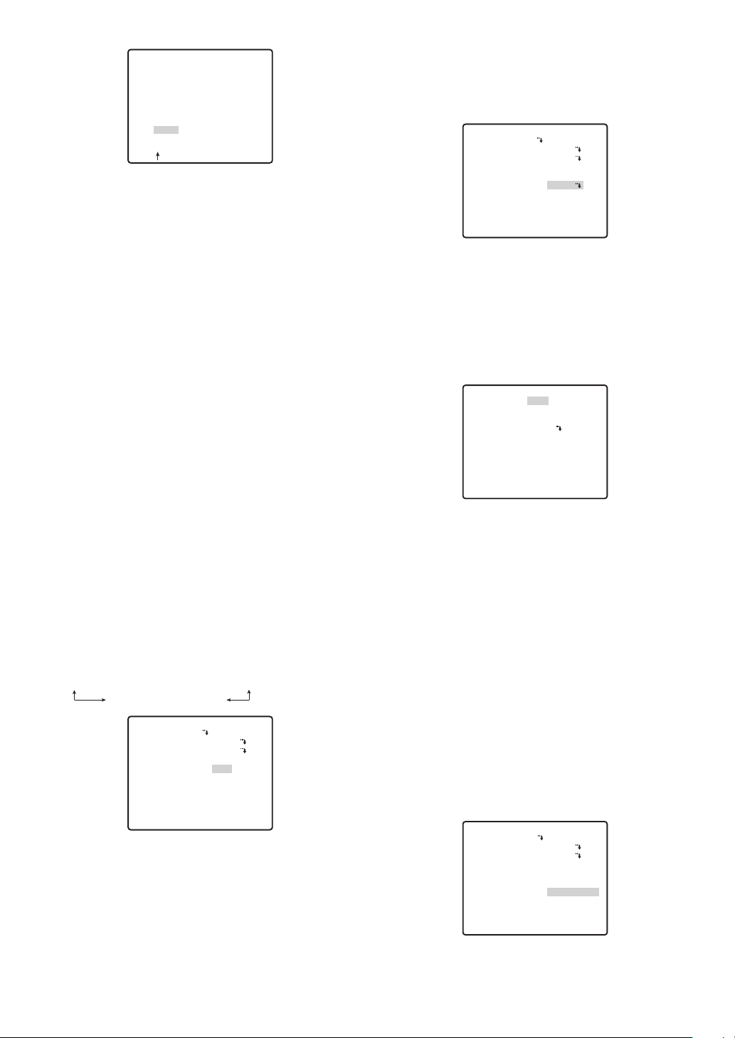
PRESET NO. 1*
0123456789
ABCDEFGHIJKLM
NOPQRSTUVWXYZ
().,'":;&#!?=
+-*/%$
SPACE
COPY POSI RET RESET
DOOR............
To copy the preset ID of another position number
Move the cursor to COPY, and then press the CAM
(SET) button. This displays the preset ID of the
position number preceding the one you are
currently configuring. Each press of the CAM (SET)
button scrolls back to the next sequential position
number and displays its preset ID.
● Light Control (ALC/MANUAL)
See page 22 and 23 for information on the setting method.
You can adjust the lens iris setting on the detailed
menu when MANUAL is set.
● Auto Focus (AF MODE)
1. Move the cursor to AF MODE, and then tilt the joystick
left or right to select an auto-focus function setting.
MANUAL S.M.L : Auto focus does not operate
after moving to a preset position.
AUTO S.M.L : Auto focus operates after
moving to a preset position.
(1) Selecting a Scene File
Use this procedure when you want to apply the
settings of a previously stored scene file when you are
configuring the settings of a preset position.
PRESET NO. 1*
POSITION SET
PRESET ID
ALC/MANUAL
AF MODE
DWELL TIME
SCENE FILE
PRESET SPEED
RET TOP DEL
ON
ALC
MANUAL L
10S
1
••••••••I
L H
1. Move the cursor to SCENE FILE, and then tilt it left
and right to select the number of the scene file you
want to select.
(2) Configuring Scene File Settings
1. Move the cursor to SCENE FILE, and then tilt it left
and right to select the number of the scene file
whose settings you want to configure.
**SCENE FILE 1**
SHUTTER
AGC
SENS UP
WHITE BAL
MOTION DET
RET TOP
OFF
ON(MID)
OFF
ATW1
OFF
● Sequence/Sort DWELL Time
(DWELL TIME)
This section explains how to set the length of time the
camera stops (time it stops rotating) and tapes the
scene while in the various preset positions for the
sequence and sort operations (page 30, 31).
1. Move the cursor to DWELL TIME, and then tilt the
joystick left or right to select a DWELL time setting.
Tilting the joystick cycles through the stop time
display in the sequence shown below. (unit: sec, min)
2S ↔ 3S ↔ 5S ↔ 10S ↔ 30S ↔ 1MIN
4MIN ↔ 3MIN ↔ 2MIN
PRESET NO. 1*
POSITION SET
PRESET ID
ALC/MANUAL
AF MODE
DWELL TIME
SCENE FILE
PRESET SPEED
RET TOP DEL
ON
ALC
MANUAL L
10S
OFF
••••••••I
L H
● Scene File Setting (SCENE FILE)
Up to 10 scene files, each of which contains camera
settings for a specific location (scene), can be stored
in memory. Scene files are managed using scene file
numbers from 1 through 10, and can be selected when
configuring preset position settings.
The following procedures explain how to select a
scene file and how to configure scene file settings.
2. Press the CAM (SET) button.
This will display the scene file setting menu.
The following items can be set on the Scene file
settings menu. See camera settings for details on
each setting.
• SHUTTER (page 23, 24)
• AGC (page 24)
• SENS UP (page 24)
• WHITE BAL (page 25)
• MOTION DET (page 36)
● Preset Speed Setting (PRESET SPEED)
Set the speed the camera moves to the various preset
positions for the sequence and sort operations (page
30, 31).
1. Move the cursor to PRESET SPEED, and then tilt the
joystick left or right to change the speed setting.
Shifting the setting towards the L side decreases the
speed, while shifting towards the H side increase it.
PRESET NO. 1*
POSITION SET
PRESET ID
ALC/MANUAL
AF MODE
DWELL TIME
SCENE FILE
PRESET SPEED
RET TOP DEL
ON
ALC
MANUAL L
10S
OFF
••••••••I
L H
-29-
Page 30
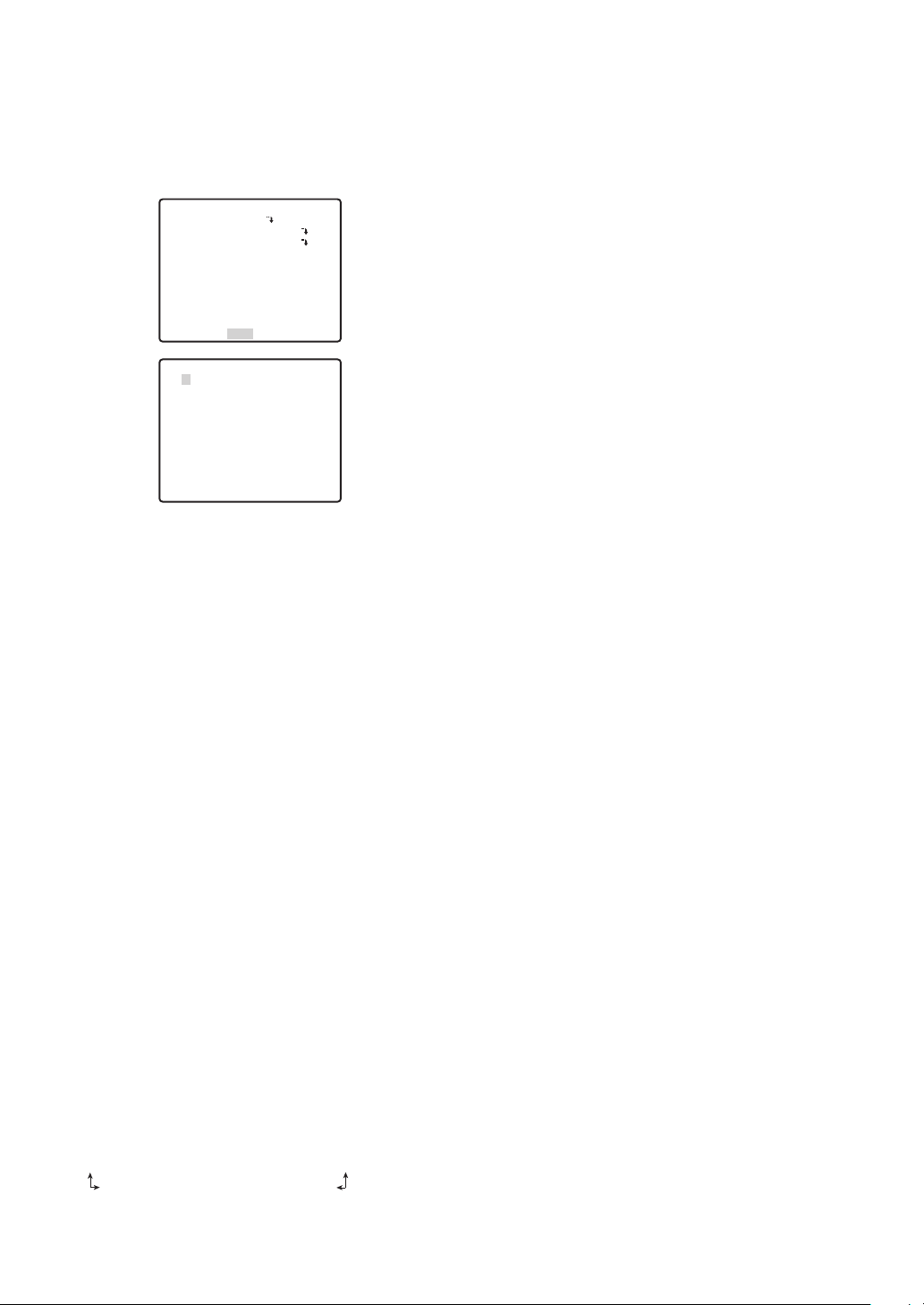
● Deleting a Preset Position (DEL)
1. Move the cursor to DEL, and then press the CAM
(SET) button.
This deletes the contents of the currently selected
position number and displays the position selection
menu.
PRESET NO. 1*
POSITION SET
PRESET ID
ALC/MANUAL
AF MODE
DWELL TIME
SCENE FILE
PRESET SPEED
RET TOP DEL
**PRESET POSITION**
2*
1
6*
5*
10*
9*
14*
13*
18*
17*
22*
21*
26*
25*
30*
29*
ID:DOOR
033-064 225-256
RET TOP
(3) Home Position Setting (HOME POSITION)
A currently configured preset position can be
designated as the home position.
Pressing the HOME button of the system controller will
cause the camera to move to the currently specified
home position. Use the following procedure to make a
preset position the home position.
1. Move the cursor to HOME POSITION, and then tilt
the joystick left or right to select the position
number of the preset position you want to make the
home position.
This causes the preset position whose position
number you select to become the home position. If
you do not want to use the home position function,
select OFF for the HOME POSITION setting.
(4) Self Return Setting (SELF RETURN)
The self return setting can be used to specify automatic
return to a particular mode if a certain amount of time
elapses without any operation being performed.
1. Move the cursor to SELF RETURN, and then tilt the
joystick left or right to select a self return trigger setting.
Tilting the joystick cycles through the self return
display in the sequence shown below. (unit: sec,
min)
OFF ↔ 1S ↔ 2S ↔ 3S ↔
60MIN
↔↔
30MIN ↔ 20MIN ↔ 10MIN ↔ 5MIN ↔ 3MIN ↔ 2MIN ↔ 1MIN
2. If you selected any setting other than OFF in step 1,
press the CAM (SET) button and then tilt the
joystick left or right to select a self return mode.
OFF ↔ AUTO ↔ HOME ↔ APAN ↔ SEQ ↔ SORT
TRK ↔ PTR4 ↔ PTR3 ↔ PTR2 ↔ PTR1
ON
ALC
MANUAL L
10S
OFF
••••••••I
L H
3*
4*
7*
8*
11*
12*
15*
16*
19*
20*
23*
24*
27*
28*
31*
32*
.......
↔ 10S ↔ 20S ↔ 30S ↔ 40S
50S
OFF : In the auto mode, exits the auto mode
when the trigger time elapses.
AUTO (AUTO MODE setting not OFF) : Returns to
the auto mode when the trigger time
elapses.
AUTO (AUTO MODE setting OFF) : Returns to the
home position when the trigger time
elapses.
HOME : Returns to the home position when the
trigger time elapses.
APAN : Activates auto pan when the trigger
time elapses.
SEQ : Activates the sequence function when
the trigger time elapses.
SORT : Activates the sort function when the
trigger time elapses.
PTR 1 to 4: Activates the patrol function when the
trigger time elapses.
TRK :After the trigger time elapses, the
camera returns to the home position
and then automatic tracking starts.
Following that, after a set time, the
camera returns to the home position
and starts to continue automatic
tracking.
Note: The HOME setting should be selected when
you want to normally leave the camera in the home
position and occasionally perform pan and tilt, or
when you want to activate SEQ.
(5) Auto Mode Setting (AUTO MODE)
Use the auto mode setting to specify the camera
movement mode (OFF, SEQ, SORT, AUTO PAN,
PATROL 1~4, AUTO TRACK).
After selecting AUTO PAN, you can use the AUTO PAN
setting menu to configure detailed settings.
1. Move the cursor to AUTO MODE, and then tilt the
joystick left or right to select a camera movement
mode setting.
OFF : Manual movement only
SEQ : Sequentially switches between
preset positions in position
number sequence. (sequential
movement)
SORT :Sequentially switches between
preset positions counterclockwise,
starting from the camera home
position. (sort movement)
AUTO PAN : Camera pans automatically within
↔↔
the range specified by PAN.
Selecting AUTO PAN and pressing
the CAM (SET) button will display
the AUTO PAN setting menu,
which can be used for configuring
detailed settings. (page 31)
PATROL 1 to 4 : Operates the camera in accordance
with patrol function settings.
-30-
Page 31

AUTO TRACK : Auto tracking is done for moving
objects under the following
conditions.
The moving object must be larger
than one of the screen blocks
(1/48 of screen area), it must have
5 % comparative contrast with the
background image.
This defines the start point and moves the
cursor to POSITION.
**AUTO PAN**
POSITION
SPEED
ENDLESS
DWELL TIME
PAN LIMIT
START
END
••••I••••
L H
OFF
1S
OFF
Notes:
• Automatic tracking covers a range from
horizontal to directly below the camera. The
digital flip function (page 34) does not operate.
Also, the pan range can be limited by using the
PAN LIMIT setting (this page).
The automatic tracking function incorporated in
this system easily tracks moving objects on
screen. Moving subjects are not automatically
tracked in the following situations.
• When multiple moving subjects are on screen
• When the subjects are moving very fast
• When the subject has little contrast
• When moving objects are either large or small
• When the image is dark
• When the image flickers
Tilting the joystick cycles through settings in the
sequence shown below.
OFF ↔ SEQ ↔ SORT ↔ AUTO PAN ↔ PATROL1 ↔ PATROL2
AUTO TRACK ↔ PATROL4 ↔ PATROL3
Notes:
• The auto mode is exited automatically whenever
manual PAN/TILT or ZOOM/FOCUS is
performed if AUTO PAN is operating and
PAN/TILT does SEQ, SORT, PATROL, or AUTO
TRACK movement. Note, however, that that the
contents of the setting menu do not change. To
return to the auto mode, open the setup menu
and then close it again. The auto mode will also
activate when the self return trigger time (page
30) elapses.
• During operation, the lens may enter the refresh
mode.
● Configuring AUTO PAN Detailed
Settings
1. Perform the following steps to set the PAN start
point and end point.
(1) Move the cursor to POSITION, press the CAM
(SET) button, and then move the cursor to START.
(2) Use the joystick to move the camera to the
desired PAN start point, and then press the
CAM (SET) button.
This defines the start point and moves the
cursor to END.
(3) Use the joystick to move the camera to the
desired PAN end point, and then press the CAM
(SET) button.
RET TOP
2. Move the cursor to SPEED and then tilt the joystick
left or right to select a panning speed setting.
Shifting the setting towards the "H" (right) side
increases the speed, while shifting towards the "L"
(left) side decreases it.
3. Move the cursor to ENDLESS, and then tilt the joystick
left or right to turn endless panning on or off.
ON : Pans from the start point to the end point,
and then continues to pan in the same
direction from the end point to the start point.
Select OFF for the PAN LIMIT setting (step 5)
when using this setting. Panning will be
repeated endlessly.
OFF : Pans from the start point to the end point,
and then reverses direction to pan from the
end point to the start point. Panning is
repeated endlessly.
4. Move the cursor to DWELL TIME, and then tilt the
joystick left or right to select the start point and end
point dwell time setting.
Tilting the joystick cycles through the stop time
display in the sequence shown below. (unit: sec)
0S ↔ 1S ↔ 2S ↔ 3S ↔ 5S ↔ 10S ↔ 20S ↔ 30S
5. Move the cursor to PAN LIMIT, and then tilt the
joystick left or right to toggle it on and off.
ON : Limits manual panning to the zone between the
start point and the end point. The TILT range is
from 0° to 90°. Select OFF for the ENDLESS
setting (step 3) when using this setting.
OFF : Allows manual panning outside the zone
between the start point and the end point.
PAN LIMIT
PAN LIMIT allows panning in the area from the start
point to the end point specified in step 1, but not in the
area from the end point to the start point.
End point
AUTO
PAN zone
Camera
Start point
PAN LIMIT
zone
Notes:
• When the panning, tilting, zooming or focusing
in the SEQ, SORT or PATROL mode is controlled
-31-
Page 32

manually, the auto mode function should be
cancelled.
To activate the auto mode, select the desired
auto mode again or set a time for SELF RETURN
in the SET UP menu.
• When 0S is selected, the camera stops without
dwelling and starts.
• Auto refreshing may be activated during the patrol
play or the auto mode to calibrate the lens position.
(6) AUTO PAN Key Setting (AUTO PAN KEY)
Set the operations of the camera when AUTO PAN is
executed from the system controller (page 31, 32).
1. Move the cursor to AUTO PAN KEY, and then tilt the
joystick left or right to select a camera movement
mode setting.
Tilting the joystick cycles through settings in the
sequence shown below.
AUTO PAN ↔ SEQ ↔ SORT ↔ PATROL1 ↔ PATROL2
AUTO TRACK ↔ PATROL4 ↔ PATROL3
Note: Auto Mode can be started, but not stopped,
with the AUTO PAN key.
(7) Patrol Function Setting (PATROL)
The patrol function remembers manual operations for
later automatic playback when they are needed.
1. Aim the camera, with the menu closed, at the start
point of the routine you want it to remember.
2. Move the cursor to NUMBER, and then tilt the
joystick left or right to specify the number of patrol
routines.
Tilting the joystick cycles through settings in the
sequence shown below. The amount of storage
time available depends on the number of routines.
The storage time display changes in the sequence
shown below. (unit: sec, min)
1(2MIN) ↔ 2(1MIN) ↔ 4(30S)
Note that the total patrol time is two minutes, and
the time allowed for each routine depends on the
number of patrol routines that are configured. The
values in parentheses indicate the time of each
patrol routine (two minutes for one pattern, one
minute each for two patterns, 30 seconds each for
four patterns).
**PATROL**
NUMBER
PATROL1*
PATROL2
PATROL3
PATROL4
RESET
RET TOP
4(30S)
PLAY
---
---
---
If you want to change the number of patrol routines
from a previous setting, first delete all of the currently
store patrol routines. To delete everything, move the
cursor to RESET, and press the CAM (SET) button.
3. Move the cursor to a PATROL number (PATROL 1
through 4), and then tilt the joystick left or right to
select a patrol setting.
--- : Disables the selected patrol routine.
PLAY : Performs the selected patrol routine.
LEARN : Select this option to teach the camera a
series of movements (patrol routine). (An
asterisk (*) to the right of a PATROL
number indicates that it already has a
patrol routine assigned to it.)
DEL→PUSH SET : Press the CAM (SET) button to
delete an existing patrol routine.
4. Turn off the menu display with the F2 button on the
system controller, and activate the patrol function
set in step 3.
Turning on the system controller's menu during a
LEARN operation causes the LEARN operation to
end. It also ends when the maximum storage time is
exceeded. Activate PLAY to check the stored
operations.
Notes:
• Selecting LEARN to teach the camera a patrol
routine causes the following parameters to be
stored along with the camera movements.
(1) Parameters at the Beginning of the Routine
• PAN, TILT, ZOOM, and FOCUS positions
• IRIS level
• Shutter speed (SHUTTER)
• Gain (AGC) setting
• Electronic sensitivity enhancement (SENS
UP) setting
• White balance (WHITE BAL) setting
•IMAGE HOLD
• AREA TITLE
• DIGITAL FLIP
• PRIVACY ZONE
• CAMERA ID
• PROPO.PT
• PAN LIMIT
• ZOOM LIMIT
• TILT ANGLE
• BURST
• CLEANING
(2) During Camera Movement
• PAN, TILT, ZOOM, and FOCUS positions
• IRIS operation
• Preset positioning
• In the patrol play mode, the camera movement
may occasionally deviate from the entered
routine when the routine includes a move to a
preset position. If this happens, re-enter the
routine of manual operations for patrol-learn.
• In the patrol play mode, black and white
automatic switching does not work.
•In the patrol play mode, when the power of the
system controller is turned on or off, the patrol
play stops. In this case, press the PATROL
PLAY button again. (If SELF RETURN is set to
ON, the patrol play will start again after elapsing
-32-
the setting return time.)
Page 33

(8) Privacy Zone Setting (PRIVACY ZONE)
The privacy zone function makes it possible to mask
specific areas of the scene (screen) from view. Up to
eight privacy zones can be configured.
Notes:
• Certain camera orientations can cause privacy
zone masked area to become visible.
• The privacy zone function does not mask scene
areas during the initialization routine performed
immediately after camera power is turned on.
• The zone position may shift if the stabilizer settings
are change after setting the privacy zone.
1. Move the cursor to PRIVACY ZONE, and then tilt the
joystick left or right to select a privacy zone setting.
ON (1) : Turns on the privacy zone function.
ON (2) : Turns on the privacy zone function. (Mosaic)
OFF :Turns off the privacy zone function.
Use the following steps to configure privacy zones.
2. Move the cursor to PRIVACY ZONE, and then press
the CAM (SET) button.
This will display the ZONE NUMBER selection menu.
The picture will be full wide angle (WIDE) if there is no
privacy zone defined for the current zone number.
**ZONE NUMBER 1 /8**
be masked, and then press the CAM (SET) button.
This registers the camera position and returns to
the zone setting menu.
** ZONE NUMBER 3 /8**
PAN/TILT
ZOOM/FOCUS
U TILT D/L PAN R
ZONE SCALE
SET DEL
RET TOP
→
PUSH SET
→
PUSH SET
••••I••••
- +
7. Move the cursor to →PUSH SET to the right of
ZOOM/FOCUS, and then press the CAM (SET) button.
This will display the ZOOM/FOCUS setting menu.
8. Move the joystick left, right, up and down to adjust
the position of the lens focus, and then press the
CAM (SET) button.
This completes the adjustment procedure and
returns to the zone setting menu.
Zoom can be set in a range of 1 to 10
magnifications.
**ZONE NUMBER 3 /8**
PAN/TILT
ZOOM/FOCUS
U ZOOM D/L FOCUS R
→
PUSH SET
→
PUSH SET
RET TOP
3. Move the cursor to ZONE NUMBER, and then tilt
the joystick left or right to select the zone number (1
to 8) you want to configure.
An asterisk (*) to the right of the a number indicates
that it already has a privacy zone configured for it.
Selecting such a zone number zooms the picture to
the zoom setting that was in effect when its privacy
zone settings were configured.
4. Press the CAM (SET) button.
This will display the zone setting menu. The
appearance of the menu depends on zone settings.
**ZONE NUMBER 3 /8**
PAN/TILT
ZOOM/FOCUS
ZONE SCALE
SET DEL
RET TOP
→
PUSH SET
→
PUSH SET
••••I••••
- +
Zone frame
The currently configured zone frame will appear in
the center of the picture.
Performing the remaining steps of this procedure
will delete the current zone frame and replace it
with the new zone frame that you configure.
5. Move the cursor to →PUSH SET to the right of
PAN/TILT, and then press the CAM (SET) button.
This will display the PAN/TILT setting menu.
6. Use the joystick to point the camera at the location to
ZONE SCALE
SET DEL
RET TOP
••••I••••
- +
9. Move the cursor to ZONE SCALE, and then tilt the
joystick left or right to change the size of the zone
frame.
Shifting the setting towards the - side makes zone
frame smaller, while shifting towards the + side
makes it larger. Note, that the aspect ratio of the
zone frame is always 3:4. Also, the size of the zone
frame that can be set changes according to the
zoom ratio.
10.Move the cursor to SET, and then press the CAM
(SET) button.
This completes the privacy zone setting procedure
and returns to the zone number selection menu.
Selecting DEL instead of SET deletes the zone
settings and returns to the zone number selection
menu.
(9) Image Hold Setting (IMAGE HOLD)
Image hold causes the current picture to be frozen until
the camera finishes moving to a preset position. This
function comes in handy when using a network interface
unit for monitoring of camera images over a network.
1. Move the cursor to IMAGE HOLD, and then tilt the
joystick left or right to toggle it on and off.
ON : Maintains the last image until the camera
finishes moving to a preset position.
However, the still image may be distorted
with the effect of panning or tilting.
OFF : Picture being picked up by the camera
continues to be displayed as the camera
moves to a preset position.
-33-
Page 34

(10) Digital Flip Setting (DIGITAL FLIP)
Normally, a camera needs to stop when it points
straight down during tilt. With digital flip, however, the
camera is able to tilt from 0° to 180° in a single motion.
This makes it possible to track objects passing directly
under the camera more smoothly. The picture is
flipped vertically and horizontally when the camera is
at an angle of around 135°.
1. Move the cursor to DIGITAL FLIP, and then tilt the
joystick left or right to toggle it on and off.
ON : Turns on digital flip. Note that the tilt range
becomes 0° to 90° when ON is selected for
the PAN LIMIT setting.
OFF : Turns off digital flip. With this setting, the tilt
range is 0° to 90°.
Notes:
• Digital flip is performed when the joystick is held
straight downwards only. It is not performed
when the joystick is tilted in any other direction.
• When OFF is selected for DIGITAL FLIP, the
following steps need to be performed in order to
tilt the camera 180°.
(1) Tilt the joystick downwards to point the
camera straight down.
(2) Tilt the joystick left or right to pan the camera
180°.
(3) Tilt the joystick upwards.
• Momentarily turn off DIGITAL FLIP and set the
zoom limit to 30x magnification or less before
setting a preset position directly from the WVCU360C System Controller. You can turn these
functions back on again after setting the preset
position.
Note that digital flip cannot be specified for the
90° to 180° tilt range.
(11) Proportional Pan/Tilt Setting (PROPO. P/T)
This function optimizes the image by automatically
adjusting the PAN/TILT (horizontal/vertical rotation)
speed according to the zoom ratio.
1. Move the cursor to PROPO.P/T, and then tilt the
joystick left or right to toggle it on and off.
ON : Pan/tilt speed is in inverse proportion to the
zoom ratio.
OFF : The speed is constant at the fastest level
regardless of the zoom ratio.
(12) Area Title Setting (AREA TITLE)
The area title function lets you display a direction
indicator that appears in the picture to indicate the
direction of the location being shown on the screen.
Text can also be displayed in place of the direction
indicators, if desired.
The direction indicators are N (north), NE (northeast), E
(east), SE (southeast), S (south), SW (southwest), W
(west), and NW (northwest).
1. Move the cursor to AREA TITLE, and then tilt the
joystick left or right to turn the area title display
function on or off.
ON (NESW) : Displays direction indicators.
Selecting ON (NESW) and pressing
the CAM (SET) button will display the
position (NESW) setting menu, which
you can use for configuring detailed
settings. (this page)
ON (USER) : Displays user input text.
Selecting ON (USER) and pressing
the CAM (SET) button will display the
area title (USER) selection menu,
which you can use for configuring
detailed settings. (page 35)
OFF : Turns off display of area title
direction indicators and text.
(1) When ON (NESW) is selected
After selecting ON (NESW), you can use the position
(NESW) setting menu to configure detailed settings.
Once you set the northerly (N) direction for the camera,
all other directions are displayed automatically.
1. Move the cursor to →PUSH SET to the right of
PAN/TILT, and then press the CAM (SET) button.
This will display the PAN/TILT setting menu.
**DIRECTION(NESW)**
PAN/TILT
ZOOM/FOCUS
POSI
+
N
RET TOP
→
PUSH SET
→
PUSH SET
2. Use the joystick to point the camera north, and then
press the CAM (SET) button.
**DIRECTION(NESW)**
PAN/TILT
ZOOM/FOCUS
POSI
U TILT D/L PAN R
+
N
RET TOP
→
PUSH SET
→
PUSH SET
3. Move the cursor to →PUSH SET to the right of
ZOOM/FOCUS, and then press the CAM (SET)
button.
This will display the ZOOM/FOCUS setting menu.
4. Move the joystick left, right, up and down to adjust
the position of the lens focus, and then press the
CAM (SET) key.
**DIRECTION(NESW)**
PAN/TILT
ZOOM/FOCUS
POSI
U ZOOM D/L FOCUS R
+
N
RET TOP
→
PUSH SET
→
PUSH SET
5. Move the cursor to POSI O, and then press the
CAM (SET) button.
This will display the ID position setting menu.
-34-
Page 35

6. Use the joystick to select an area title display
position, and then press the MON (ESC) button.
This registers the area title display position and
returns to the area title (NESW) setting menu.
FLOOR 1
N
Note: The area title is always displayed under the
camera ID. If you specify different display position
settings for the camera ID and the area title ID, the
area title ID display position setting is used for both.
In the example screen shown in step 1, NORTH O
is the title name of area title number 1.
4. Input an area title.
The text input procedure is the same as that for
camera ID input.
See steps 3 through 5 under “(1) Camera ID
(CAMERA ID)” on page 22 for information about
inputting the text for the area title and specifying its
position on the display.
AREA TITLE 1
0
123456789
ABCDEFGHIJKLM
NOPQRSTUVWXYZ
().,'":;&#!?=
+-*/%$
SPACE
---- POSI RET RESET
................
(2) When ON (USER) is selected
After selecting ON (USER), you can use the area title
(USER) setting menu to configure detailed settings.
You can use the following procedure to configure
direction settings, and to input text associated with a
particular direction indicator.
1. Move the cursor to 1, and then press the CAM
(SET) button.
This will display the position setting menu. An asterisk
(*) to the right of an area title number indicates that it
already has an area title assigned to it.
If the there is already text associated with the
direction you selected, it will appear under the
cross mark (+). If there is no text associated with
the direction, only the cross mark (+) will be
displayed.
**AREA TITLE(USER)**
1
*
NORTH
2
3
4
5
6
7
8
RET TOP RESET
2. Adjust the camera orientation (pan and tilt), zoom,
and focus.
Perform steps 1 through 4 under “(1) When ON
(NESW) is selected” on page 34.
**DIRECTION(USER) 1**
PAN/TILT
ZOOM/FOCUS
+
NORTH
RET TOP DEL
→PUSH SET
→
PUSH SET
3. Move the joystick to the right to align the cursor with
the title display, and press the CAM (SET) button.
This will display the area title setting menu.
FLOOR 1
NORTH
5. Repeat steps 1 through 4 for the other area
numbers, if you want.
(13) Tilt Angle Setting (TILT ANGLE)
Selecting 5° for the TILT ANGLE setting allows tilting
past horizontal, in the range of -5° to 185°.
1. Move the cursor to TILT ANGLE, and then tilt the
joystick left or right to toggle the setting between 0°
and 5°.
Notes:
• Zooming to WIDE while 5° is selected for the
TILT angle setting will cause the upper half of
the picture to become hidden.
• With certain subjects, AGC (gain control) can
cause the image to become white.
(14) Cleaning Settings (CLEANING)
This camera uses a "slip ring" for transmission of
electrical power and signals. A dirty slip ring can cause
deterioration of picture quality and generation of noise.
The cleaning function performs cleaning approximately
once a week to keep the slip ring clean.
1. Move the cursor to CLEANING, and then tilt the
joystick left or right to toggle it on and off.
The text CLEANING appears in the center of the
screen while the cleaning process is being
performed.
Note: Select OFF for CLEANING before performing
an upload or download data with a system device.
This protects against the download or upload failure
due to start up of the cleaning process.
-35-
Page 36

ALARM SETTINGS
■ Using the Alarm Setup Menu
Display the alarm setup menu from the setup menu to
configure alarm settings.
First, display the alarm setup menu.
1. Display the setup menu (page 21), move the cursor
to ALARM O, and then press the CAM (SET) button.
**ALARM SETUP**
MOTION DET OFF
PRESET ALM OFF
ALARM IN/OUT
RET TOP
This will display the alarm setup menu.
* The following sections numbered q to e explain
how to use each of the alarm setup menu items.
(1) Motion Detector Setting (MOTION DET)
1. Move the cursor to MOTION DET, and then tilt the
joystick left or right to toggle it on and off.
OFF : Turns off the motion detector.
MODE 1 :Alarm signal is output when motion is
detected in the image. Selecting MODE 1
and pressing the CAM (SET) button displays
the mode 1 setting menu, which can be
used for configuring detailed settings.
MODE 2 :Alarm signal is output when the camera is
covered by cloth, a lid, spray paint or
something.
Motion Detector
The motion detector divides the screen into 48 blocks
and monitors changes in the luminance in each block.
When it detects any change (movement) in the image,
it outputs an alarm signal. When a change (movement)
in the image is detected while in the auto mode, the
alarm signal is output and the camera stops at the
preset position for a specified amount of time.
q
e
w
**MODE1**
LEVEL
DWELL TIME
DISPLAY MODE
ALARM
MASK SET
RECOVER TIME
RET TOP
••••I••••
- +
2S
OFF
OFF
2. Mask the areas of the screen that you do not want
the motion detector to monitor for movement.
To mask screen areas, use the same procedure as
step 3 under "SUPER-D 3 (Super Dynamic 3)" on
page 23. After configuring mask settings, press the
MON (ESC) button to return to the motion detector
setting menu.
3. Move the cursor to ALARM, and then tilt the joystick
left or right to toggle demo mode (see step 5) alarm
output on and off.
ON : Turns on alarm output in the demo mode.
OFF : Turns off alarm output in the demo mode.
4. Move the cursor to DISPLAY MODE, and then press
the CAM (SET) button.
This activates the demo mode.
Demo Mode
The demo mode divides the screen into 48 blocks and
monitors changes in the luminance in each block. It
also masks any part of the picture where there is a
change in average luminance that exceeds the
currently specified detection sensitivity level. The demo
mode results can be used to determine the optimum
detection sensitivity level (step 5) and the areas of the
screen that need to be masked (step 1).
5. Move the cursor to LEVEL, and then tilt the joystick
left or right to set the detection sensitivity level.
Shifting the setting towards the + side increases
sensitivity, while shifting towards the - side
decreases it. Repeat steps 4 and 5 until the
optimum sensitivity level is obtained.
Important! Conditions for Mode 2
Monitoring might not be possible in the following
situations.
• If only one part of the screen is not covered, or if
the covering is translucent
Also, false detection might occur in the following situations.
• When extreme changes in lighting occur, such as
turning lights on an off
• If pedestrian or vehicle traffic is heavy
● Configuring Detailed Motion Detector
Settings for MODE 1
1. Move the cursor to MASK SET O, and then press
the CAM (SET) button.
This will display the mask setting screen.
Detection Conditions
Object Size : The moving object must be larger
than one of the screen blocks (1/48
of the total screen area).
Subject Contrast: The contrast ratio between the
background and the moving object
must be at least 5% (at the
maximum LEVEL setting).
Object Speed : The allowable time range for the
object to pass from one edge of the
screen to the other is 0.1 second to
0.8 second. Movement that is faster or
slower than this cannot be detected.
Important : Size and speed limitations are
relaxed somewhat when the contrast
ratio between the background and
the moving object is large.
-36-
Page 37

6. Move the cursor to DWELL TIME, and then tilt the
joystick left or right to select an alarm detect dwell
time setting.
After alarm detection, the next alarm is not detected
until the specified dwell time elapses.
Tilting the joystick cycles through the setting
display in the sequence shown below. (unit: sec)
2S ↔ 5S ↔ 10S ↔ 30S
7. Move the cursor to RECOVER TIME, and then tilt
the joystick left or right to select an alarm reset time
setting.
Tilting the joystick cycles through the setting
display in the sequence shown below. (unit: sec,
min)
If you set OFF, then it does not reset until some other
operation is done. If AUTO TRACK is set, the camera
starts automatic tracking when change (movement)
is detected in the image during SEQ or SORT
.
OFF ↔ 1MIN ↔ 2MIN ↔ 3MIN ↔ 5MIN ↔ 10MIN
AUTO TRACK ↔ 60MIN ↔ 30MIN ↔ 20MIN
Notes:
• Monitoring is usually done in SEQ mode, and
when the camera detects change (movement)
automatic tracking starts. To have the camera
return to SEQ mode after a certain amount of
time, set the SELF RETURN setting to SEQ.
• Use the mask setting to mask areas where there
is wind movement of curtains, etc.
• Use a lower sensitivity level (LEVEL) setting for
areas where illumination is low and prone to
digital noise. Also note that operation error can
occur when the illuminance of a subject is
changed suddenly by the headlights of passing
cars, turning lights on or off, etc.
• There is a delay of about 0.2 second from the
point that the camera detects change
(movement) in the image and the point that a
signal is sent to the alarm terminal of a VCR, etc.
• Alarms are not output while the setting menu is
displayed, unless demo mode alarm output is
turned on.
• Alarms are not output when PAN, TILT, ZOOM,
FOCUS or other functions are operating.
• When the motion detector is set to MODE 1 or
MODE 2, it outputs alarm data during the
blanking period. This can cause operational
problems for a VCR or other device that uses a
time code signal, etc. Turn off the motion
detector when not using coaxial communication.
• The motion detector is not intended for use as
specialty device for the prevention of theft, fire,
etc. The manufacturer assumes no responsibility
for any accidents that occur or any losses
incurred while this product is being used.
(2) Preset Alarm Setting (PRESET ALM)
Turning on the preset alarm will output an alarm from
the video output port or alarm output connector when
the camera completes a move to a preset position. An
alarm is output in the following cases.
• When the self return function is activated (page 30)
and the camera finishes moving to the home
position, and when switching to the auto mode.
• When SEQ is selected for the auto mode (page 30),
and the camera completes a move to a preset
position during sequential movement
• When SORT is selected for the auto mode (page
30), and the camera completes a move to a preset
position during SORT movement
• When AUTO PAN is selected for the auto mode
(page 30), and the camera completes a preset
move up to the AUTO PAN start point
• When the camera completes a move to a preset
position during manual operation
• When PLAY is selected for the auto mode (page
32), and the camera completes a preset move up to
the patrol start point
Use the following procedures to configure preset alarm
settings
1. Move the cursor to PRESET ALM, and then tilt the
joystick left or right to toggle it on and off.
ON : Turns on the preset alarm function.
OFF : Turns off the preset alarm function.
Note: Turn off the preset alarm function before
downloading or uploading preset data.
(3) Alarm Input/Output (ALARM IN/OUT)
Use this setting to specify what operation the camera
should perform when it an alarm signal is input to the
alarm input connector or output from the alarm output
connector.
Note: While the camera is in the AF mode or the
lens moves between WIDE and TELE, alarm input
may be ignored if several alarm inputs are received
in succession.
1. Move the cursor to the ALARM IN/OUT O and then
press the CAM (SET) button.
This will display the alarm setting menu.
2. Move the cursor to ALARM IN 1, and then tilt the
joystick left and right to select the operation the
camera should perform when an external signal is
received by ALARM IN 1.
OFF : Ignore alarm input signals.
1POSI : Move to preset position 1.
AUTOPAN : Start auto pan.
PATROL1 : Start PATROL 1.
PATROL1 (S) : Start PATROL 1, and maintain the
stored picture quality settings
(page 32) even after completion.
AUTOTRACK1 : Move to preset position number 1,
and then perform auto tracking.
**ALARM IN/OUT**
ALARM IN1 OFF
ALARM IN2 OFF
ALARM IN3 OFF
ALARM IN4 OFF
CNT-CLS 1 OFF
TIME OUT 100MS
CNT-CLS 2 OFF
COAX ALM OUT OFF
RET TOP
-37-
Page 38

3. Move the cursor to ALARM IN 2, and then tilt the
joystick left and right to select the operation the
camera should perform when an external signal is
received by ALARM IN 2.
OFF : Ignore alarm input signals.
2POSI : Move to preset position 2.
SEQ : Start sequential movement.
PATROL2 : Start PATROL 2.
PATROL2 (S) : Start PATROL 2, and maintain the
stored picture quality settings
(page 32) even after completion.
AUTOTRACK2 : Move to preset position number 2,
and then perform auto tracking.
4. Move the cursor to ALARM IN 3, and then tilt the
joystick left and right to select the operation the
camera should perform when an external signal is
received by ALARM IN 3.
OFF : Ignore alarm input signals.
3POSI : Move to preset position 3.
SORT :Start sort movement.
PATROL3 : Start PATROL 3.
PATROL3 (S) : Start PATROL 3, and maintain the
stored picture quality settings
(page 32) even after completion.
AUTOTRACK3 : Move to preset position number 3,
and then perform auto tracking.
5. Move the cursor to ALARM IN 4, and then tilt the
joystick left and right to select the operation the
camera should perform when an external signal is
received by ALARM IN 4.
OFF : Ignore alarm input signals.
4POSI : Move to preset position 4.
BW : Black and white display while
signal is being input.
PATROL4 : Start PATROL 4.
PATROL4 (S) : Start PATROL 4, and maintain the
stored picture quality settings
(page 32) even after completion.
AUTOTRACK4 : Move to preset position number 4,
and then perform auto tracking.
Notes:
•
Use PATROL 1 (S) to 4 (S) if you want to switch
picture quality (for example to switch picture quality
from day to night) when an alarm input is received.
ALARM IN4 can be used combined with BW.
To use the camera with this application, set the
picture quality you want to switch before registering
the patrol, then start the patrol registration and then
end the registration immediately.
•
If you want to change the picture quality settings
according to alarm input for PATROL 1 (S) to 4 (S),
the settings are applied to the camera settings and
are kept even after the camera is turned on again.
6. Move the cursor to CNT-CLS 1, and then tilt the
joystick left and right to select the alarm output that
should be performed over ALARM OUT 1 when an
alarm is detected.
OFF : No alarm output
ALARM : Output an alarm signal when an
alarm is detected by the motion
detector (page 36) or the preset
alarm (page 37). After selecting this
setting, perform step 7 to specify
the alarm signal output time.
AUX1 : Output a contact close signal
when AUX1 input is received from
the system controller.
7. If you selected ALARM in step 6, move the cursor to
TIME OUT and then tilt the joystick left and right to
select the alarm signal output time.
Tilting the joystick cycles through the output time
display in the sequence shown below. (unit: ms)
100 MS ↔ 200 MS ↔ 1000 MS ↔ 2000 MS ↔ 4000 MS
Note: The shorter the duration, the more
frequent will be the detection output.
8. Move the cursor to CNT-CLS 2, and then tilt the
joystick left and right to select the alarm output that
should be performed from ALARM OUT 2 when an
alarm is detected.
OFF : No alarm output
BW : Output a contact close signal only
while the camera is in the black
and white mode.
AUX2 : Output a contact close signal
when AUX2 input is received from
the system controller.
Note: It is recommended to set the connected
external device to ignore the shorter alarm outputs
of 90 ms or less from the camera.
9. Move the cursor to COAX ALM OUT, and then tilt
the joystick left or right to toggle it on and off.
This setting turns alarm controls whether an alarm is
output when the camera moves to one of the preset
positions specified for ALARM IN 1 through 4 (1POSI,
2POSI, 3POSI, 4POSI) in steps 2 through 5, above.
ON : Output an alarm signal from the
video output connector at the
point the camera finishes moving
to a preset position (number 1
through 4) when there is alarm
input to ALARM IN (1 through 4).
OFF : No alarm signal output
Notes:
• The camera ignores alarm inputs during manual
operation.
• Turn off alarm outputs before downloading or
uploading preset data.
-38-
Page 39

SPECIAL SETTINGS
■ Using the Special Setup Menu
Display the special setup menu from the setup menu to
adjust picture quality.
First, display the special setup menu.
1. Display the setup menu (page 21), move the cursor
to SPECIAL O, and then press the CAM (SET)
button.
This will display the special setup menu.
**SPECIAL SETUP**
CHROMA GAIN
AP GAIN
PEDESTAL
HUE
PIX OFF
REFRESH →PUSH SET
CAMERA RESET
SER.NO. BFB03964
RET TOP
● Adjusting Picture Quality
Use the following procedure to adjust picture quality.
1. Move the cursor to CHROMA GAIN, and then tilt the
joystick left or right to adjust the CHROMA GAIN level.
2. Move the cursor to AP GAIN, and then tilt the
joystick left or right to adjust the aperture level.
3. Move the cursor to PEDESTAL, and then tilt the
joystick left or right to adjust the PEDESTAL level.
4. Move the cursor to HUE, and then tilt the joystick
left or right to adjust the chroma phase (color tone).
5. Move the cursor to PIX OFF O, and then press the
CAM (SET) button.
This will display the PIX OFF menu. Perform the
following steps to perform blemish compensation
on the pixels.
6. Select a position that has a blemish with the PIX
OFF number, and then press the CAM (SET) button.
This will display the blemish compensation pattern
setting screen.
(1) Use the joystick to move the cross cursor ( ) to
the location of the defective pixels.
(2) Move the cursor around the display until there
are no more white spots (blemishes) visible, and
then press the CAM (SET) button.
This will store the blemish compensation pattern.
(3) This returns to the PIX OFF menu.
An asterisk (*) to the right of a PIX OFF number
indicates that the number has a blemish
compensation pattern assigned to it.
••••••I••
•••I•••••
••I••••••
••••I••••
- +
→
PUSH SET
To delete a blemish compensation pattern
(1) On the PIX OFF menu screen, select of the
pattern you want to delete, and press the CAM
(SET) button.
This will display the blemish compensation
pattern setting screen.
(2) Press the F3 button.
(3) This returns to the PIX OFF menu.
This will delete the blemish compensation
pattern and remove the asterisk (*) to the right of
the applicable pattern number.
7. To correct for camera deviation from the preset
positions during operation, move the cursor to
→PUSH SET to the right of REFRESH, and then
press the F3 button.
The refresh function corrects the camera position
when it starts to deviate from the preset positions. If
you are not using the WV-CU650C system
controller, perform one of the following steps to
correct the camera position.
8. To reset the camera to its initial default settings,
move the cursor to →PUSH SET to the right of
CAMERA RESET, and then press the F4 button.
This resets the camera to it initial factory default
settings. Note, however, that this does not change
the camera's preset position, AUTO PAN, patrol,
RS485, blemish compensation patter and password
settings.
If you are not using the WV-CU650C system controller,
perform one of the following steps to reset the camera.
Note: If above operations are performed while the
cursor is located at any other item besides
CAMERA RESET, further menu operations may
become impossible. If this happens, use the
procedure under "Displaying the Setup Menu" on
page 21 to re-display the menu.
** PIX OFF **
1*
2* 3* 4*
5* 6* 7* 8
9 10 11 12
13 14 15 16
000 000
RET TOP
-39-
Page 40

SCENE SELECT SETTING
■ Using the Scene Select Setting
Menu
Display the scene select setting menu from the setup
menu to configure scene select settings. First, display
the scene select setting menu.
1. Display the setup menu (page 21), move the cursor
to SCENE SELECT O, and then press the CAM
(SET) button.
This will display the scene select setting menu.
**SCENE SELECT**
SCENE INDOOR(L)
LOAD
RET TOP
● Scene Select Settings
Use the following procedure to configure scene select
settings.
1. Move the cursor to SCENE, and then tilt the joystick
left or right to change the scene setup.
INDOOR (L) : Indoor setting (picture quality
priority)
INDOOR (H) : Indoor setting (sensitivity
priority)
OUTDOOR (L) : Outdoor setting (picture
quality priority)
OUTDOOR (H) : Outdoor setting (sensitivity
priority)
Settings related to the picture switch depending on
the scene settings. Scene select settings and
relationship to other settings are shown in the table
below.
AGC SENS UP SHUTTER BW DNR WHITE BAL
INDOOR (L) MID OFF OFF OFF LOW ATW1
INDOOR (H) HIGH ×2 AUTO OFF OFF HIGH ATW1
OUTDOOR (L) MID OFF AUTO AUTO LOW ATW2
OUTDOOR (H) HIGH ×2 AUTO AUTO AUTO HIGH ATW2
2. Move the cursor to LOAD, and then press the CAM
(SET) button.
This will cause the setup you selected for SCENE in
step 1 to be applied to the image.
-40-
Page 41

QUICK MENU SETTINGS
■ Displaying the Quick Setup Menu
The quick setup menu can be displayed from the setup
menu.
1. Display the setup menu (page 21), move the cursor
to → QUICK SETUP, and then press the CAM (SET)
button.
Only the following items can be set on the quick
setup menu.
• Camera ID setting (page 22)
• Scene select settings (page 40)
• Preset position settings (page 27)
• Language settings (page 21)
MODEL WV-CS954
CAMERA ID OFF
SCENE SELECT
PRESET POSITION
LANGUAGE
→
ADVANCED SETUP
The procedures for configuring settings using the
quick setup menu are the same as those for the
detailed menu.
To switch back to the detailed menu from the quick
setup menu, move the cursor to →ADVANCED SET
UP, and then press the CAM (SET) button.
-41-
Page 42

PASSWORD SETTINGS
■ Password Lock Settings
Set the password lock on the setup menu.
● Turning Password Lock On and Off
The password lock function can be used to allow only
authorized personnel to change camera settings. A
password must be input in order to turn password lock
on or off.
ON : Prohibits changing any settings except for
the password lock function.
Selecting this setting limits camera
configuration changes to authorized personnel.
OFF : Settings on all menus can be changed.
If you are using a VCR for recording, turn off recording
before inputting the password. Inputting the password
while the picture is being recorded by a VCR will cause
the password to be recorded with the picture.
1. Display the setup menu (page 21), move the cursor
to PASSWORD LOCK (ON or OFF), and then press
the CAM (SET) button.
MODEL WV-CS954
CAMERA
PAN/TILT
ALARM
SPECIAL
COMMUNICATION
SCENE SELECT
LANGUAGE
→QUICK SETUP
PASSWORD LOCK OFF
This will display the password input menu.
2. To set the password for the first time, enter the
factory default password "123" and then press the
CAM (SET) button.
Note: You must use this procedure. The password
Lock ON/OFF does not switch.
3. Input a 3-digit password by moving the cursor to
each of the applicable numbers along the top of the
screen (0 to 9) and pressing the CAM (SET) button
** PASSWORD? **
0 1 2 3 4 5 6 7 8 9
. . .
OK RESET
NEW PASSWORD
RET TOP
Note: The factory default password is 123.
4. Press the CAM (SET) button.
This returns to the setup menu and toggles
PASSWORD LOCK on or off.
The password input screen will reappear if you
press the CAM (SET) button after inputting the
wrong password. If this happens, perform steps 2
and 3 again.
● Changing the Password
After turning on password lock, it is recommended that
you use the following procedure to change the factory
default password to a different one. Also, make sure
you keep a separate record of your password so you
do not forget it.
If you are using a VCR for recording, turn off recording
before inputting the password. Inputting the password
while the picture is being recorded by a VCR will cause
the password to be recorded with the picture.
1. Display the setup menu (page 21), move the cursor
to PASSWORD LOCK (ON or OFF), and then press
the CAM (SET) button.
This will display the password input menu.
MODEL WV-CS954
CAMERA
PAN/TILT
ALARM
SPECIAL
COMMUNICATION
SCENE SELECT
LANGUAGE
→QUICK SETUP
PASSWORD LOCK OFF
2. Input the current 3-digit password by moving the
cursor to each of the applicable numbers along the
top of the screen (0 to 9) and pressing the CAM
(SET) button for each digit.
The ↑ pointer will move to the right each time you
input a digit. After you input all three digits, move
the cursor to OK.
If you make a mistake during input, move the cursor
to RESET, press the CAM (SET) button, and then reinput the entire password.
** PASSWORD? **
0 1 2 3 4 5 6 7 8 9
. . .
for each digit.
The ↑ pointer will move to the right each time you
input a digit. After you input all three digits, move
the cursor to OK.
If you make a mistake during input, move the cursor
to RESET, press the CAM (SET) button, and then reinput the entire password.
-42-
OK RESET
NEW PASSWORD
RET TOP
Page 43

3. Move the cursor to NEW PASSWORD and press the
CAM (SET) button to display the password setting
menu.
The password input screen will reappear if you
press the CAM (SET) button after inputting the
wrong password. If this happens, perform steps 2
and 3 again.
4. Input the new 3-digit password by moving the
cursor to each of the applicable numbers along the
top of the screen (0 to 9) and pressing the CAM
(SET) button for each digit.
After you input all three digits, move the cursor to
OK.
** NEW PASSWORD? **
0 1 2 3 4 5 6 7 8 9
. . .
. . .
OK RESET
RET TOP
5. Press the CAM (SET) button.
This returns to the new password input screen
again for verification.
Note that you cannot register the new password by
pressing the MON (ESC) button.
6. Input the new 3-digit password again by moving the
cursor to each of the applicable numbers along the
top of the screen (0 to 9) and pressing the CAM
(SET) button for each digit.
After you input all three digits, move the cursor to
OK.
7. Press the CAM (SET) button.
This completes the password change operation
and returns to the setup menu. If the new password
you input in step 6 is different from the one you
input in step 4, the new password input screen will
appear again. If this happens, perform steps 4
through 7 again. Note that you cannot register the
new password by pressing the MON (ESC) button.
-43-
Page 44

SHORTCUTS
Shortcuts are supported when you are using the system controller that has a CAM FUNCTION button. With shortcuts,
you can configure camera functions by inputting function codes on the 10-key pad and then pressing the CAM
FUNCTION button.
The following is a list of all of the shortcuts that are supported by this camera. In addition, you can also move the
camera to a preset position by inputting the applicable position number on the 10-key pad.
Notes:
• Turn off digital flip before registering preset positions. If NO REGS.; FLIP ON appears, do the setting again.
• Shortcuts may not be performed if they are executed while a pan, tilt, zoom, or focus operation is in progress.
• Shortcuts 1 through 64, 169, 170, and 301~556 can be saved as part of a patrol routine.
• Except for shortcuts 169 and 170, executing any shortcut during patrol routine PLAY will cause the PLAY
operation to stop.
Controller Operation Setting
[6] + [5] + [CAM FUNCTION] AUTO PAN ON
[6] + [6] + [CAM FUNCTION] AUTO PAN OFF
[6] + [7] + [CAM FUNCTION] Increases AUTO PAN speed one step.
[6] + [8] + [CAM FUNCTION] Decreases AUTO PAN speed one step.
[6] + [9] + [CAM FUNCTION] Sets AUTO PAN start point.
[7] + [0] + [CAM FUNCTION] Sets AUTO PAN end point.
[7] + [1] + [CAM FUNCTION] AUTO MODE: OFF
[7] + [2] + [CAM FUNCTION] AUTO MODE SEQ: OFF
[7] + [3] + [CAM FUNCTION] AUTO MODE SEQ: SORT ON
[7] + [4] + [CAM FUNCTION] Reverses AUTO PAN range.
[7] + [6] + [CAM FUNCTION] ENDLESS: ON
[7] + [7] + [CAM FUNCTION] ENDLESS: OFF
[7] + [8] + [CAM FUNCTION] DIGITAL FLIP: ON
[7] + [9] + [CAM FUNCTION] DIGITAL FLIP: OFF
[8] + [0] + [CAM FUNCTION] PROPO.P/T: ON
[8] + [1] + [CAM FUNCTION] PROPO.P/T: OFF
[8] + [4] + [CAM FUNCTION] SUPER-D 3: ON
[8] + [5] + [CAM FUNCTION] SUPER-D 3: OFF
[8] + [6] + [CAM FUNCTION] AF MODE: AUTO
[8] + [7] + [CAM FUNCTION] AF MODE: MANUAL
[8] + [8] + [CAM FUNCTION] Performs auto focus.
[8] + [9] + [CAM FUNCTION] Moves to home position.
[9] + [0] + [CAM FUNCTION] BW: ON
[9] + [1] + [CAM FUNCTION] BW: OFF
[9] + [2] + [CAM FUNCTION] BW: AUTO
[9] + [3] + [CAM FUNCTION] CAMERA ID: ON
[9] + [4] + [CAM FUNCTION] CAMERA ID: OFF
[9] + [5] + [CAM FUNCTION] AREA TITLE: ON (NESW)
[9] + [6] + [CAM FUNCTION] AREA TITLE: ON (USER)
[9] + [7] + [CAM FUNCTION] AREA TITLE: OFF
[1] + [0] + [0] + [CAM FUNCTION] Adjusts camera position (REFRESH)
[1] + [0] + [1] + [CAM FUNCTION]
[1] + [6] + [4] + [CAM FUNCTION]
[1] + [6] + [5] + [CAM FUNCTION] PATROL1: PLAY
[1] + [6] + [6] + [CAM FUNCTION] PATROL 1 - PATROL 4: STOP
[1] + [6] + [7] + [CAM FUNCTION] PATROL1: LEARN start
[1] + [6] + [9] + [CAM FUNCTION] IRIS: OPEN
Stores preset to first available preset number (1 to 64).
-44-
Page 45

Controller Operation Setting
[1] + [7] + [0] + [CAM FUNCTION] IRIS: CLOSE
[1] + [7] + [1] + [CAM FUNCTION] SHUTTER: ON
[1] + [7] + [2] + [CAM FUNCTION] SHUTTER: OFF
[1] + [7] + [3] + [CAM FUNCTION] Increases shutter speed one step.
[1] + [7] + [4] + [CAM FUNCTION] Decreases shutter speed one step.
[1] + [7] + [5] + [CAM FUNCTION] AGC: ON
[1] + [7] + [6] + [CAM FUNCTION] AGC: OFF
[1] + [7] + [7] + [CAM FUNCTION] SENS UP: FIX ON
[1] + [7] + [8] + [CAM FUNCTION] SENS UP: FIX OFF
[1] + [7] + [9] + [CAM FUNCTION] Increases electronic sensitivity enhancement (FIX) one step.
[1] + [8] + [0] + [CAM FUNCTION] Decreases electronic sensitivity enhancement (FIX) one step.
[1] + [8] + [1] + [CAM FUNCTION] SENS UP: AUTO ON
[1] + [8] + [2] + [CAM FUNCTION] SENS UP: AUTO OFF
[1] + [8] + [3] + [CAM FUNCTION] Increases electronic sensitivity enhancement (AUTO) one step.
[1] + [8] + [4] + [CAM FUNCTION] Decreases electronic sensitivity enhancement (AUTO) one step.
[1] + [8] + [5] + [CAM FUNCTION] Increases line lock phase (FINE) one step.
[1] + [8] + [6] + [CAM FUNCTION] Decreases line lock phase (FINE) one step.
[1] + [8] + [7] + [CAM FUNCTION] Pans 180° .
[1] + [8] + [8] + [CAM FUNCTION] CLEANING: ON
[1] + [8] + [9] + [CAM FUNCTION] CLEANING: OFF
[1] + [9] + [0] + [CAM FUNCTION] BW AUTO switching time: 10 seconds
[1] + [9] + [1] + [CAM FUNCTION] BW AUTO switching time: 30 seconds
[1] + [9] + [2] + [CAM FUNCTION] BW AUTO switching time: 60 seconds
[1] + [9] + [3] + [CAM FUNCTION] BW AUTO switching time: 300 seconds
[1] + [9] + [4] + [CAM FUNCTION] PATROL2: PLAY
[1] + [9] + [5] + [CAM FUNCTION] PATROL3: PLAY
[1] + [9] + [6] + [CAM FUNCTION] PATROL4: PLAY
[1] + [9] + [7] + [CAM FUNCTION] PATROL2: LEARN start
[1] + [9] + [8] + [CAM FUNCTION] PATROL3: LEARN start
[1] + [9] + [9] + [CAM FUNCTION] PATROL4: LEARN start
[2] + [0] + [0] + [CAM FUNCTION] Turns on auto tracking.
[2] + [0] + [1] + [CAM FUNCTION] STABILIZER: ON
[2] + [0] + [2] + [CAM FUNCTION] STABILIZER: OFF
[2] + [0] + [3] + [CAM FUNCTION] PAN, TILT, ZOOM, coordinate display ON
[2] + [0] + [4] + [CAM FUNCTION] PAN, TILT, ZOOM, coordinate display OFF
[3] + [0] + [1] + [CAM FUNCTION]
[5] + [5] + [6] + [CAM FUNCTION] Example: Preset number 128 → [4] + [2] + [8] + [CAM FUNCTION]
[6] + [0] + [1] + [CAM FUNCTION]
[8] + [5] + [6] + [CAM FUNCTION] Example: Preset number 128 → [7] + [2] + [8] + [CAM FUNCTION]
* Do not do this operation with the previous dome type camera models (WV-CS850 series, WV-CS854, WV-CS854E series, WV-CW860 series,
WV-CW864, WV-CW864E series, and WV-CS564), doing so may cause a malfunction.
Moves to a preset number (1 to 256).*
Registers a position to a preset number (1 to 256).*
-45-
Page 46

TROUBLESHOOTING
Before requesting service, check the following symptoms to see if you can solve the problem yourself.
If the countermeasures described below do not correct the problem, or if the symptoms you are experiencing are not
covered here, contact a quality service person or system installer.
Problem Cause and Recommended Action
No picture (dark screen)
White picture
• Is the camera connected correctly? Check the
operating instructions that come with your system
controller.
• Is the lens iris closed?
Execute the iris reset from the system controller you
are using.
• Is the camera set up for a fixed shutter speed?
• Is the lens iris open?
• Is FIX selected for the electronic sensitivity
enhancement (SENS UP) setting?
Reference Pages
—
22-23
23
22-23
24
Out of focus picture
Digital noise in the
picture
• Is the dome cover or lens of the camera dirty? If so,
clean them.
• Is MANUAL selected for the auto focus mode?
• Is the object one that is not compatible with auto
focus? For such objects, focus manually.
• The slip ring may be dirty. Do you have the
cleaning function turned on?
• Is the camera set up correctly?
-46-
7
26
26
35
11
Page 47

Problem
Cause and Recommended Action
Reference Pages
Poor picture color
Image flicker
Afterimages in
the picture
Black and white picture
picture
• Check the white balance setting.
• Use the special setup menu to adjust picture
quality.
• Is the dome cover or lens of the camera dirty? If so,
clean them.
• If Super Dynamic 3 is turned on, turn it off.
• Check the DNR setting.
• The camera has an auto black and white switching
mode function. Check the setting of this mode.
25
39
7
22-23
25
25-26
Frequent switching
between the color and
the black and white
modes
White specks in the
picture
Menu does not open.
• Adjust the black and white mode switching level,
and the duration time setting.
• Use the PIX OFF function to perform blemish
compensation.
• Is the camera connected correctly? See the
operating instructions that come with the system
controller you are using.
• Are camera communication settings configured
correctly?
25-26
39
—
12-14
18-19
20
-47-
Page 48

Problem
Cause and Recommended Action
Reference Pages
Menu settings will not
change.
I forgot the password.
Picture does not switch
to black and white.
Pan, tilt, zoom, or focus
do not work.
• Is the password lock function turned on?
• Contact a quality service person or system installer.
• Switching is not performed when the ALARM IN 4
setting is BW. Check the setting.
• Is the camera connected correctly? See the
operating instructions that come with the system
controller you are using.
• The camera has a pan limit function. Check the
PAN LIMIT settings.
42
—
38
—
31
The camera movement
modes (OFF, SEQ,
SORT, AUTO PAN,
PATROL, AUTO
TRACK) do not work.
• The motor or lens may be worn. Contact a quality
service person or system installer.
• Check the self return function.
• Check the ALARM IN settings.
• Check the recover time setting of the motion
detector.
—
30
37-38
36-37
-48-
Page 49

Problem
The camera movement
mode (OFF, SEQ,
SORT, AUTO PAN,
PATROL, AUTO
TRACK) setting
changes.
Cause and Recommended Action
• Check the self return function.
Reference Pages
30
Camera position is
different from the
• Perform REFRESH from the special setup menu.
preset position setting.
Picture is different from
the position setting.
• Adjust the picture using the preset menu and a
scene file.
Upper part of the picture
is black when the camera
is in a horizontal
• This is caused by the camera's internal cover. It
does not indicate malfunction.
orientation.
• If the cleaning function is turned on, this is normal
does not indicate malfunction. Check the
Camera suddenly starts
CLEANING settings.
to pan by itself.
• If the cleaning function is not turned on, this
symptom could be due to noise.
● Periodically check the power cord and plug.
39
27-29
35
35
8, 12
Power cord sheathing is
damaged.
Power cord, connectors,
or power plug becomes
hot during operation.
Power cord becomes
warm or hot when it is
bent or stretched during
use.
• The power cord, connector, or power plug is damaged. Continued
use creates the risk of electric shock and fire. Immediately unplug
the power plug and contact a qualified service person or system
installer for servicing.
-49-
Page 50

SPECIFICATIONS
● General
Power Requirements 24 V AC, 60 Hz
Power Consumption 13 W
Pick-up Device 1/4-type {1/4"} interline transfer CCD
Effective Pixels 768 (H) × 494 (V)
Scanning Area 3.65 mm (H) × 2.74 mm (V)
Signal NTSC
Synchronization Internal (INT), multiplexed vertical drive (VD2), link-lock (LL)
Scanning 2:1 interlace
Scanning Frequencies Horizontal: 15.734 kHz, Vertical: 59.94 Hz
Video Output VBS: 1.0 V [P-P]/75 Ω (BNC plug)
Resolution (Center) Horizontal : 480 lines minimum (color NORMAL mode)
540 lines typ. , 520 lines minimum (color HIGH mode)
570 lines minimum (black and white)
Vertical : 350 lines minimum (Center)
Minimum Illumination 0.5 lux{fc} (color mode)
0.04 lux{fc} (black and white mode)
SENSE UP: OFF; AGC: HIGH
Dynamic Range 52 dB typ. (SUPER-D3: ON)
S/N Ratio 50 dB minimum (AGC: OFF)
Ambient Operating Temperature -10 °C to 50 °C; Humidity 90 % max. (non-condensation)
Dimensions 154.5 mm(D) × 233 mm(H) {6-5/64"(D) × 9-11/64"(H)}
Weight Approximately 2.2 kg {4.9 lbs}
Finish Camera:
Dome: Clear acrylic resin
Die cast aluminum with baked melanin coating (Paint color: Fine silver)
● Pan and Tilt
Panning Range 360 ° endless
Panning Modes Manual, auto, manual position, sequential position
Panning Speed* Manual: Approximately 0.065 °/s to 120 °/s 8 steps, 16 steps, 64 steps
Preset: Approximately 400 °/s
Tilting Range -5 ° to 185 ° (horizontal - vertical - horizontal)
(According to the TILT ANGLE)
Tilting Modes Manual, manual position, sequential position
Tilting Speed* Manual: Approximately 0.065 °/s to 120 °/s 8 steps, 16 steps, 64 steps
Preset: Approximately 400 °/s
* Actual speed depends on type of controller being used.
● Lens
Zoom Ratio 30x (Approximately 300x with digital zoom)
Focal Length 3.8 mm to 114 mm
Maximum Aperture Ratio 1:1.4 (WIDE) to 3.7 (TELE)
Object Distance 1.5 m
Iris Range F1.4 to 22, Close
Angular Field of View Horizontal: 1.9 ° (TELE) to 52 ° (WIDE)
Vertical: 1.4 ° (TELE) to 40 ° (WIDE)
-50-
Page 51

● Main Functions
Controller Interface Coaxial Multiplex System, RS485
Control Functions Pan and tilt, zoom and focus, 256 preset positions, home position, patrol
AGC ON (LOW), ON (MID), ON (HIGH), OFF
Title (ID) ON, OFF (Preset ID, camera ID, area title: 16 alphanumeric characters)
Zoom Speed Approximately 6.0 seconds (TELE to WIDE) in manual mode
Zoom Limit 1x to 300x (Over 30x is electronic zoom)
Password Lock All menus
Auto Focus MANUAL/AUTO (PAN, TILT, ZOOM linked)
Iris ALC (Adjustable OPEN/CLOSE output target level)/MANUAL
Shutter OFF (1/60), AUTO, 1/100, 1/250, 1/500, 1/1000, 1/2000, 1/4000, 1/10000
Electronic Sensitivity Enhancement 32X max. (AUTO or FIX)
Auto Mode OFF, SEQ, SORT, AUTO PAN, PATROL, AUTO TRACK
Auto Pan Key SEQ, SORT, AUTO PAN, PATROL, AUTO TRACK
Digital Flip ON/OFF
SUPER-D3 ON/OFF
Motion Detector OFF/MODE1/MODE2
Alarm Input/Output 4 inputs (ALARM IN 1 to ALARM IN 4)
2 outputs (ALARM/AUX1, BW/AUX2)
Black and White Mode Switching AUTO/ON/OFF
Privacy Zone ON/OFF (8 zone settings)
Patrol STOP/PLAY/LEARN
Cleaning ON/OFF
Image Hold ON/OFF
Auto Image Stabilizer ON/OFF
Scene Select Setting INDOOR (L) /INDOOR (H) /OUTDOOR (L) /OUTDOOR (H)
Language Setting Japanese, English, German, French, Italian, Spanish, Russian, Chinese
-51-
Page 52

VERSION FRANÇAIS
(FRENCH VERSION)
CAUTION ATTENTION
RISK OF ELECTRIC SHOCK DO NOT OPEN
RISQUE DE CHOCS ELECTRIQUES NE PAS OUVRIR
ATTENTION:
AFIN DE PRÉVENIR LE RISQUE DE CHOCS
ÉLECTRIQUES, NE PAS RETIRER LES VIS.
TOUTE RÉPARATION DEVRAIT ÊTRE
CONFIÉE À UN PERSONNEL QUALIFIÉ.
L'éclair à extrémité fléchée placé dans
un triangle équilatéral est destiné à
attirer l'attention de l'utilisateur sur la
présence d'une "tension potentiellement dangereuse" et non isolée se
trouvant dans les limites du coffret de
SA 1965
SA 1966
l'appareil dont la puissance est suffisante pour constituer un risque important d'électrocution.
Le point d'exclamation placé dans un
triangle équilatéral sert à attirer l'attention de l'utilisateur sur des instructions
de fonctionnement et d'entretien (de
dépannage) à caractère important
dans la brochure qui accompagne l'appareil.
Cet appareil numérique de la classe A est conforme à la
norme NMB-003 du Canada.
L’interférence radioélectrique générée par cet appareil
numérique de type A ne dépasse pas les limites radioélectriques, section appareil numérique, du Ministère des
Communications.
Le numéro de série de l'appareil se trouve sur la
plaque supérieure.
Nous vous conseillons de relever le numéro de série
de votre appareil dans l'espace réservé ci-dessous
et de conserver précieusement votre notice d'instructions en tant que justificatif d'achat aux fins d'identification en cas de vol.
No. de modèle WV-CS954
No. de série
MISE EN GARDE: Afin de prévenir tout risque d’incendie ou d'électrocution, éviter d’exposer cet appareil à la pluie
ou à une humidité excessive. Èviter d’exposer l’appareil aux égouttements d'eau et aux
éclaboussures et s'assurer qu'aucun objet rempli de liquide, tels que des cases, ne soit placé
sur l'appareil.
-52-
Page 53

INSTRUCTIONS DE SÉCURITÉ IMPORTANTES
1) Veuillez lire ces instructions.
2) Conservez ces instructions.
3) Tenir compte de tous les avertissements.
4) Conformez-vous à toutes les instructions.
5) Ne pas utiliser cet appareil près de lieux en présence d'eau.
6) Nettoyer uniquement avec un chiffon sec.
7) N'obturer aucune des ouvertures d'aération. Installer conformément aux instructions du fabricant.
8) Ne pas utiliser à proximité de sources de chaleur telles que des radiateurs, des bouches de chauffage, des appareils
de chauffage ou tout autre appareil (y compris les amplificateurs) produisant de la chaleur.
9) Ne pas asservir l'objectif de sécurité de la prise polarisée ou de la prise de mise à la terre. Une prise polarisée possède
deux lames dont l'une est plus large que l'autre. Une prise de mise à la terre possède deux lames ainsi qu'un troisième
élément, un ergot de mise à la terre. La lame qui est large ou le troisième élément, l'ergot, sont installés pour assurer
votre sécurité. Si la prise fournie ne s'engage pas correctement dans votre prise, veuillez consulter un électricien pour
qu'il effectue le remplacement de l'ancienne prise de sortie secteur.
10) Protéger le cordon d'alimentation afin que personne ne marche dessus ni ne soit pincé, notamment au niveau des
prises, les prises pratiques et les points de sortie de l'appareil.
11) Utiliser uniquement les fixations ou les accessoires spécifiés par le fabricant.
12) Utiliser uniquement le chariot, le support, le trépied, la platine de fixation ou la tablette spécifiée par le fabricant ou
vendu avec l'appareil. Quand un chariot est utilisé, prendre toutes les précautions nécessaires lors du déplacement de
la combinaison chariot-appareil afin que le tout ne se renverse pas.
S3125A
13) Débrancher cet appareil pendant les orages électriques ou s'il n'est pas utilisé sur de longues périodes de temps.
14) Toute réparation ou dépannage doit Ítre confié à un personnel qualifié. Un dépannage est nécessaire lorsque l'appareil
a été endommagé d'une manière quelconque, par exemple, lorsque le cordon d'alimentation électrique ou la prise sont
endommagés, si un liquide s'est répandu dessus ou si des objets sont tombés dans l'appareil, lorsque l'appareil a été
exposé à la pluie ou à l'humidité, ne fonctionne pas normalement ou s'il a fait une chute.
FRANÇAIS
-53-
Page 54

LIMITATION DE RESPONSABILITÉ
CETTE PUBLICATION EST FOURNIE "COMME TEL" SANS
GARANTIE DE TOUTE SORTE, EXPRÈS OU IMPLICITE,
ÉTANT INCLUSE MAIS NON LIMITÉE AUX GARANTIES
IMPLICITES DE LA VALEUR MARCHANDE, ADAPTATION
POUR TOUT BUT PARTICULIER OU NON-INFRACTION
DES DROITS D'UN TIERS.
DÉNI DE LA GARANTIE
EN AUCUN CAS MATSUSHITA ELECTRIC INDUSTRIAL
CO., LTD. NE PEUT ÊTRE TENU POUR RESPONSABLE
POUR TOUT PARTI OU TOUTE PERSONNE, À L'EXCEPTION DE DU REMPLACEMENT OU D'UN ENTRETIEN
RAISONNABLE DE CE PRODUIT POUR LES CAS, Y
COMPRIS MAIS NON LIMITÉ À CE QUI EST MENTIONNÉ
CI-DESSOUS:
(1) TOUT DÉGÂT ET PERTE, Y COMPRIS SANS LIMITA-
TION, DIRECT OU INDIRECT, SPÉCIAL, IMPORTANT
OU EXEMPLAIRE, SURVENANT OU CONCERNANT
LE PRODUIT;
(2) BLESSURE PERSONNELLE OU TOUT DÉGÂT
CAUSÉS PAR UN USAGE NON APPROPRIÉ OU UNE
UTILISA-TION NÉGLIGENTE DE L'UTILISATEUR;
(3) DÉMONTAGE, RÉPARATION OU MODIFICATION
NON AUTORISÉS DU PRODUIT EFFECTUÉS PAR
L'UTILISA-TEUR;
(4) LES INCONVÉNIENTS OU PERTES QUI SURVIEN-
NENT SI LES IMAGES NE SONT PAS AFFICHÉES, DU
FAIT D'UNE QUELCONQUE RAISON OU CAUSE
INCLUANT UNE QUELCONQUE PANNE OU
PROBLÈME INHÉRENT AU PRODUIT.
CETTE PUBLICATION A PU INCLURE DES INEXACTITUDES TECHNIQUES OU DES ERREURS
TYPOGRAPHIQUES. DES CHANGEMENTS SONT
AJOUTÉS AUX INFORMATION CI-DESSUS, À TOUT
MOMENT, AUX FINS D'AMÉLIORATION DE CETTE PUBLICATION ET/OU DU PRODUIT CORRESPONDANT (S).
(5) TOUT PROBLÈME, INCOMMODITÉ IMPORTANTE DE
CONSÉQUENCE OU PERTE OU ENDOMMAGEMENT,
SURVENANT DU SYSTÈME COMBINÉ PAR DES
APPAREILS DE TIERS.
(6) TOUTE RÉCLAMATION OU ACTION ENTREPRISE
POUR DES DOMMAGES, APPORTÉE PAR TOUTE
PERSONNE OU ORGANISATION ÉTANT UN SUJET
PHOTOGÈNE, DÛ À LA VIOLATION DE L'INTIMITÉ
AVEC POUR RÉSULTAT DES IMAGES DE SURVEILLANCE DE CAMÉRA VIDÉO, Y COMPRIS DES
DONNÉES SAUVEGARDÉES, POUR UNE RAISON
QUELCONQUE, EST DIFFUSÉE PUBLIQUEMENT OU
EST EMPLOYÉE POUR UN BUT AUTRE QUE CELA
DE LA SURVEILLANCE
(7) TOUT PROBLÈME, INCOMMODITÉ CONSÉCUTIVE
IMPORTANTE OU PERTE OU DOMMAGES, SUR-
VENANT DE LA DÉTECTION INAPPROPRIÉE OU
INTRODUCTION DANS LA DÉTECTION PAR LA
FONCTION VMD (Détection de mouvement vidéo) DU
PRODUIT.
-54-
Page 55

DÉNI DE LA GARANTIECARACTÉRISTIQUES
Cette caméra couleur CCTV est un appareil de
vidéosurveillance qui incorpore un dispositif à transfert de
charge CCD de 1/4 de pouce, un zoom grossissant 30x,
préréglée et des capacités de balayage panoramique et
de réglage d’inclinaison dans une configuration en dôme.
Cet appareil offre également les caractéristiques
suivantes.
■ Super Dynamic 33(SUPER-D 33)
Le processeur SUPER-D 3 rend possible la capture
d’images claires de sujets diversement éclairés.
■
Nouveau DSP pour une haute sensibilité
Un nouveau système de réduction de bruit réduit la
luminance minimum à 0,5 lux{fc} en mode couleur et à
0,04 en mode noir et blanc.
■ Passage automatique de nuit en mode
Noir et blanc
Cette caméra peut être configurée de manière à passer
automatiquement en mode noir et blanc dans des
conditions de faible lumière pour obtenir des images
claires même de nuit.
■ Digital Flip (retournement numérique)
Une caméra doit normalement s’arrêter pour pointer vers
le bas pendant une opération de retournement. Avec le
retournement numérique, la caméra peut s’incliner de 0 à
180 ° d’un seul mouvement. Il devient ainsi possible de
suivre sans problème des sujets passant directement sous
la caméra
■ Fonction Zone de confidentialité
La fonction Zone de confidentialité permet de masquer
des zones spécifiques de manière qu’elles n’apparaissent
pas.
■ Fonction Patrouille
La fonction patrouille garde en mémoire les mouvements
de routine manuels de la caméra pour pouvoir les relire en
cas de nécessité. Vous pouvez ainsi apprendre à la
caméra les mouvements des personnes à surveiller, en
relisant les paramètres mis en mémoire, les mouvements
automatiques sont faits automatiquement.
■ Mémoire de position caméra
Le système peut être configuré avec 256 positions caméra
au maximum. Une position caméra particulière peut être
sélectionné et vue en saisissant le numéro de préréglée
applicable sur le clavier à 10 touches.
■ Détection de mouvement
Le système peut être configuré de sorte que le moindre
mouvement sur l’écran de surveillance déclenche
l’émission d’un signal d’alarme.
Cette fonction peut être utilisée avec un système de
magnétoscope pour enregistrer des images d'intrusion
nocturne.
Fonctionnement de la bascule numérique
Inclinaison vers
le bas
. . . La bascule numérique est effectuée uniquement lorsque la manette de
contrôle est tenue vers le bas.
L’image se retourne
lorsque la caméra est
pointée vers le bas
(environ 135°).
Inclinaison vers
le haut.
ACCESSOIRES
Mode d’emploi (ce manuel) . . . . . . . . . . . . . . . . . . . . .1 él
Certificat de garantie . . . . . . . . . . . . . . . . . . . . . . . . . .1 él
Les éléments suivants sont nécessaires à l’installation.
Couvercle décoratif . . . . . . . . . . . . . . . . . . . . . . . . . . .1 él
Feuille de protection contre la poussière . . . . . . . . . . .1 él
Câble d’alarme 8P . . . . . . . . . . . . . . . . . . . . . . . . . . . .1 él
Câble d’alarme 4P . . . . . . . . . . . . . . . . . . . . . . . . . . . .1 él
Connecteur pour 24 V CA . . . . . . . . . . . . . . . . . . . . . .1 él
ACCESSOIRES EN OPTION
Couvercle de dôme (transparent à environ 50 %, type fumé) . . . . .WV-CS3S
Support de montage plafond . . . . . . . . . . . . . . . . . . . . . . . . . . . . . . .WV-Q105/WV-Q116/WV-Q117
Support de montage mural . . . . . . . . . . . . . . . . . . . . . . . . . . . . . . . .WV-Q118
-55-
Page 56

MESURES DE PRÉCAUTIONS
1. Ne jamais tenter de démonter la caméra.
Pour éviter tout risque d’électrocution, ne pas enlever
vis ou couvercles.
Il n’y a aucune pièce réparable par l’utilisateur à
l’intérieur.
Adressez-vous à des techniciens dépanneurs qualifiés
pour toute réparation.
2. Manipuler soigneusement la caméra.
Ne pas employer improprement la caméra. Évitez de la
secouer, de lui faire subir des chocs etc. La caméra
pourrait être endommagée par de mauvaises
conditions de rangement ou de manipulation.
3. Ne jamais exposer la caméra à la pluie ou à l’humidité, et n’essayez pas de la faire fonctionner en zone
humide.
Ce produit est destiné à une utilisation en intérieur ou à
des lieux abrités de la pluie ou de l’humidité.
Mettez l’appareil immédiatement hors tension et
demandez l’aide d’un technicien qualifié pour le
dépannage.
L’humidité peut endommager la caméra et créer un
danger d'électrocution.
4. Ne jamais se servir de détergents abrasifs et violents pour nettoyer le caisson de la caméra.
Utilisez un chiffon sec pour nettoyer la caméra en cas
de besoin.
Si la saleté est difficile à enlever, utilisez un détergent
doux et frottez délicatement. Il faut faire extrêmement
attention à ne pas rayer le dôme en l’essuyant.
Avec un chiffon sec retirez toute trace de détergent
pour terminer.
5. Ne jamais pointer la caméra vers le soleil.
Que la caméra soit ou non en service, ne la pointez
jamais directement vers le soleil ou vers d’autres objets
extrêmement lumineux. Cela peut entraîner un traînage
ou une hyper luminosité.
6. Ne dirigez jamais la caméra vers de puissantes
sources d’éclairage pendant de longs moments
Une lumière telle celle d’un projecteur risque de
favoriser la formation d’une tache rémanente sur
l’écran d’affichage. Le fait de ne pas respecter cette
mise en garde, peut produire une image décolorée
suite à la détérioration du filtre couleur intégré dans le
dispositif à transfert de charge CCD.
7. Ne jamais installer cette caméra en position
inversée.
Cette caméra est conçue pour être installée sur un
plafond ou un mur. Le fait de l’installer en position
inversée par exemple sur un plancher, peut avoir pour
effet d’empêcher un fonctionnement normal.
8. Ne jamais faire fonctionner la caméra dans des conditions excédant ses limites d’utilisation en termes
de température, d’humidité ou de puissance d’alimentation.
Evitez d’utiliser la caméra dans un milieu extrême avec
des conditions de température ou d’humidité très
élevées. La caméra ne doit pas être placée près de
sources de chaleur telles que des radiateurs, des
poêles ou tout autre appareil produisant de la chaleur.
Elle doit être utilisée dans des conditions de
température ambiante située entre -10 °C et + 50 °C
{14 °F - 122 °F} (et de préférence +40 °C {104 °F})
avec une humidité inférieure à 90 %.
La source d’alimentation est de 24 V de courant
alternatif 60 Hz.
9. La caméra ne doit pas être installée près d’une
bouche d’aération d'air conditionné.
L’objectif risque de s’embuer en raison de la
condensation si la caméra vidéo est utilisée dans les
conditions suivantes.
• Variations rapides de température suite à la mise en
marche ou l’arrêt de l’air conditionné.
• Variations rapides de température en raison d'une
ouverture et d'une fermeture fréquentes des portes.
• Utilisation dans un environnement où les lunettes
s’embuent.
• Utilisation dans une pièce remplie de fumée de
cigarettes ou de poussière.
Si l’objectif s’embue, suite à une condensation, retirez
le couvercle du dôme et éliminez l’humidité des
surfaces avec un chiffon doux.
10. Pièces de remplacement
Les pièces munies de contacts telles que les moteurs
d’entraînement d’objectif, le moteur du ventilateur de
refroidissement et les bagues collectrices à l'intérieur
de la caméra vidéo, sont sujettes à usure avec le
temps. Demandez au centre après vente le plus
proche d’effectuer le remplacement et l’entretien de
ces pièces.
11. Ne pas diriger la caméra vidéo vers le même sujet
pendant un long moment.
Une rémanence d’image risque de se produire sur
l’écran fluorescent du tube à rayons cathodiques.
12. Fonction d’auto diagnostic
Si la caméra vidéo continue de fonctionner de façon
anormale pendant plus de 30 secondes du fait de
problème tels des bruits externes, elle redémarre
automatiquement. Si cela se produit fréquemment,
vérifiez s’il existe une raison liée à l’environnement.
* Nous, Matsushita Electric Industrial Co., Ltd. déclarons
ci-après que nous ne serions être tenu pour
responsable des dommages survenus, directs ou
indirects, par l’utilisation de ce produit pour une
transaction commerciale ou pour la sécurité, ou par un
défaut de son fonctionnement.
-56-
Page 57

PRÉCAUTIONS PENDANT LE FONCTIONNEMENT
■ La caméra vidéo n’est pas équipée d’un commuta-
teur d’alimentation.
La mise sous tension est immédiate dès que le cordon
d’alimentation est branché. Avant de procéder au
nettoyage de la caméra vidéo, débranchez le cordon
d’alimentation de la prise de courant.
■ Que faire si le message OVER HEAT apparaît sur
l’écran
Ce message indique que la température interne de la
caméra vidéo est très chaude. Débranchez immédiatement
le cordon d’alimentation de la prise de courant et contactez un technicien ou un installateur système qualifiés.
■ Notez les recommandations suivantes pour vous
assurer, à long terme, un fonctionnement sans
problème.
Une utilisation prolongée dans des températures et une
humidité élevées peut entraîner la détérioration des
composants et peut abréger la durée de vie de la caméra
vidéo.
La température ambiante de fonctionnement recommandée
est située à moins de +35 °C.
Veillez à ce que la caméra soit installée dans un
emplacement qui ne soit pas exposé à la chaleur directe
d'un radiateur, chauffage etc.
■ Évitez d’utiliser cette caméra vidéo dans des lieux
où se prépare de la cuisine et dans des endroits d’où
se dégagent de grandes quantités de vapeur d’eau et
d’huile.
■ A propos de la fonction de nettoyage de la caméra
Une utilisation prolongée peut provoquer des bruits sur le
moniteur et dérégler les positions préréglées.
Si de telles conditions persistent même après avoir effectué un nettoyage de la caméra vidéo (page 86), allez au
Menu pour activer et exécuter la fonction "RAFRAICHIR"
(page 90).
Si vos utilisez un sélecteur matriciel avec une fonction de
nettoyage de caméra vidéo (WJ-SX550C), configurez le
réglage de nettoyage automatique du sélecteur matriciel
de manière que le nettoyage soit effectué une fois par
jour.
■ La caméra vidéo est uniquement prévue pour fonc-
tionner en position suspendue.
Ne pas l’utiliser dans une autre position comme par
exemple posée sur la surface d’une table, au sol etc. De
telles conditions d’utilisation peuvent provoquer des
dysfonctionnements.
■ Rémanence d’image sur le filtre couleur du dispositif
de transfert de charge CCD
Une lumière intense concentrée sur un point pendant une
longue période, peut entraîner une détérioration du filtre
couleur intégré dans le dispositif à transfert de charge
CCD et une décoloration de la partie affectée. Même si la
position de la caméra vidéo est modifiée, la décoloration
persiste à l’endroit où la lumière s’était concentrée.
■ Ne pas pointer la caméra en direction d'une source
lumineuse violente.
Une lumière intense comme celle d’un projecteur
concentré sur un endroit de l’écran, peut provoquer une
hyper luminosité (arc en ciel autour de la forte lumière) ou
un traînage (des rayures verticales au-dessus et audessous de la forte lumière).
Sujet lumineux
Traînage
Hyper luminosité
■ Ne pas diriger la caméra vidéo vers le même sujet
pendant un long moment.
Une rémanence d’image risque de se produire sur l’écran
fluorescent du tube à rayons cathodiques.
■ Manipuler soigneusement la caméra.
Ne pas faire tomber la caméra ou lui faire subir de choc
ou de vibration. Cela peut entraîner un dysfonctionnement
de l’appareil.
■ Ne pas mouiller la caméra.
Veillez à ce qu’elle ne soit pas directement exposée à
l’eau. Cela peut entraîner un dysfonctionnement de
l’appareil.
■ Condensation à l’intérieur du couvercle du dôme
Retirez le couvercle du dôme et utilisez un chiffon doux
pour éliminer l’humidité.
■ Consommables
Les pièces munies de contacts telles que les moteurs
d’entraînement d’objectif, le moteur du ventilateur de
refroidissement et les bagues collectrices à l'intérieur de la
caméra vidéo, sont sujettes à usure avec le temps.
Demandez au centre après vente le plus proche
d’effectuer le remplacement et l’entretien de ces pièces.
■ Nettoyage de la caméra vidéo
Mettez la caméra hors tension et nettoyez-la à l’aide d’un
chiffon doux. Si elle est très sale, essuyez la caméra avec
un chiffon doux humecté d’un mélange très dilué d’eau et
de détergent de cuisine neutre. Essorez bien le chiffon
avant d'essuyer la caméra. Puis avec un chiffon sec et
doux retirez tout trace d’humidité.
Un couvercle de dôme ou un objectif sali risque de
détériorer la qualité de l’image. Utilisez du papier à
nettoyer les lunettes pour nettoyer l'objectif.
Le couvercle du dôme est particulièrement susceptible
d’être endommagé.
Essuyez le soigneusement avec un chiffon doux.
-57-
Page 58

Téléchargement (sauvegarde) ou télétransmission
■
(récupération) les paramètres de la caméra vidéo
Les paramètres de la caméra qui peuvent être
téléchargées du contrôleur système etc., incluent les
réglages existants de positions préréglées et les réglages
de menu. En revanche, les éléments suivants ne sont pas
inclus.
• Fonction Patrouille (page 82)
• Fonction Titre de zone (page 84)
• Motifs de compensation d’imperfections (page 90)
• Réglages RS485 (page 70)
• Réglages du mot de passe (page 93)
Veillez à ce que les fonctions énumérées ci-dessous
soient toutes désactivées avant de télécharger du
contrôleur etc. les données de préréglage ou de
télécharger ces données vers la caméra. Le
téléchargement de ou vers un système ne se fera pas
normalement si l'une de ces fonctions est activée.
•Alarme (page 88)
•Alarme préréglée (page 88)
• Nettoyage (page 86)
• Détecteur de mouvement (page 87)
• Mode auto (page 80)
• Retour automatique (page 80)
Lors du téléchargement des données de préréglage du ou
sur le système, pointez la caméra en direction d’un mur ou
de quelque chose de similaire de manière qu'il y ait aussi
peu de mouvement que possible.
Le téléchargement des données de préréglage du WVCS954 vers d’autres modèles (par exemple WV-CS854,
WV-CS854A, WV-CS854B et WV-NS324) peut entraîner
des erreurs ou l’échec du processus de téléchargement.
■ Fonction d’auto-diagnostic
Si un dysfonctionnement dû à un bruit externe ou à tout
autre raison se prolonge au-delà de 30 secondes, la
caméra se réinitialise automatiquement et se remet à
fonctionner normalement. C’est la même procédure de
réinitialisation que celle de la mise sous tension de la
caméra. Si une réinitialisation est trop souvent requise,
cela pourrait vouloir dire que la caméra est installée dans
un lieu où il y a trop de bruits externes. Ceci peut entraîner
un dysfonctionnement de la caméra, vous devez donc
contacter le plus rapidement possible un technicien ou un
installateur système qualifiés.
-58-
Page 59

TABLE DES MATIÈRES
INSTRUCTIONS DE SÉCURITÉ IMPORTANTES . . . . . . . . . . . . . . . . . . . . . . . . . . . . . . . . . .53
LIMITATION DE RESPONSABILITÉ . . . . . . . . . . . . . . . . . . . . . . . . . . . . . . . . . . . . . . . . . . . .54
DÉNI DE LA GARANTIE . . . . . . . . . . . . . . . . . . . . . . . . . . . . . . . . . . . . . . . . . . . . . . . . . . . . .54
CARACTÉRISTIQUES . . . . . . . . . . . . . . . . . . . . . . . . . . . . . . . . . . . . . . . . . . . . . . . . . . . . . . .55
■ Super Dynamic 3 (SUPER-D 3) . . . . . . . . . . . . . . . . . . . . . . . . . . . . . . . . . . . . . . . . . . .55
■ Nouveau DSP pour une haute sensibilité . . . . . . . . . . . . . . . . . . . . . . . . . . . . . . . . . . . . .55
■ Passage automatique de nuit en mode Noir et blanc . . . . . . . . . . . . . . . . . . . . . . . . . . .55
■ Digital Flip (retournement numérique) . . . . . . . . . . . . . . . . . . . . . . . . . . . . . . . . . . . . . . .55
■ Fonction Zone de confidentialité . . . . . . . . . . . . . . . . . . . . . . . . . . . . . . . . . . . . . . . . . . .55
■ Fonction Patrouille . . . . . . . . . . . . . . . . . . . . . . . . . . . . . . . . . . . . . . . . . . . . . . . . . . . . . .55
■ Mémoire de position caméra . . . . . . . . . . . . . . . . . . . . . . . . . . . . . . . . . . . . . . . . . . . . . .55
■ Détection de mouvement . . . . . . . . . . . . . . . . . . . . . . . . . . . . . . . . . . . . . . . . . . . . . . . . .55
ACCESSOIRES . . . . . . . . . . . . . . . . . . . . . . . . . . . . . . . . . . . . . . . . . . . . . . . . . . . . . . . . . . . .55
ACCESSOIRES EN OPTION . . . . . . . . . . . . . . . . . . . . . . . . . . . . . . . . . . . . . . . . . . . . . . . . . .55
MESURES DE PRÉCAUTIONS . . . . . . . . . . . . . . . . . . . . . . . . . . . . . . . . . . . . . . . . . . . . . . . .56
PRÉCAUTIONS PENDANT LE FONCTIONNEMENT . . . . . . . . . . . . . . . . . . . . . . . . . . . . . . .57
CONSTRUCTION . . . . . . . . . . . . . . . . . . . . . . . . . . . . . . . . . . . . . . . . . . . . . . . . . . . . . . . . . .60
PRÉCAUTIONS POUR L’INSTALLATION . . . . . . . . . . . . . . . . . . . . . . . . . . . . . . . . . . . . . . . .61
RÉGLAGES DES INTERRUPTEURS DIP . . . . . . . . . . . . . . . . . . . . . . . . . . . . . . . . . . . . . . . .62
■ Paramètres de communications (Interrupteur DIP 2) . . . . . . . . . . . . . . . . . . . . . . . . . . .62
■ Numéro de caméra vidéo déterminé (Interrupteur DIP 1) . . . . . . . . . . . . . . . . . . . . . . . .63
■ Paramètres de communication RS485 (Interrupteur DIP 1) . . . . . . . . . . . . . . . . . . . . . . .64
INSTALLATION DE LA CAMÉRA VIDÉO . . . . . . . . . . . . . . . . . . . . . . . . . . . . . . . . . . . . . . . .65
■
Préparation de la caméra et du couvercle décoratif pour une sortie latérale du câble
■ Installation de la caméra vidéo . . . . . . . . . . . . . . . . . . . . . . . . . . . . . . . . . . . . . . . . . . . .65
ENLEVER LA CAMÉRA . . . . . . . . . . . . . . . . . . . . . . . . . . . . . . . . . . . . . . . . . . . . . . . . . . . . . .67
■ Retrait du couvercle décoratif . . . . . . . . . . . . . . . . . . . . . . . . . . . . . . . . . . . . . . . . . . . . .67
■ Enlever la caméra vidéo . . . . . . . . . . . . . . . . . . . . . . . . . . . . . . . . . . . . . . . . . . . . . . . . . .67
BRANCHEMENTS . . . . . . . . . . . . . . . . . . . . . . . . . . . . . . . . . . . . . . . . . . . . . . . . . . . . . . . . . .68
RS485 AJUST . . . . . . . . . . . . . . . . . . . . . . . . . . . . . . . . . . . . . . . . . . . . . . . . . . . . . . . . . . . . .70
UTILISATION DU MENU DE CONFIGURATION . . . . . . . . . . . . . . . . . . . . . . . . . . . . . . . . . .71
■ Affichage du menu de configuration . . . . . . . . . . . . . . . . . . . . . . . . . . . . . . . . . . . . . . . .71
■ Réglage de langue . . . . . . . . . . . . . . . . . . . . . . . . . . . . . . . . . . . . . . . . . . . . . . . . . . . . . .71
RÉGLAGES DE LA CAMÉRA VIDÉO . . . . . . . . . . . . . . . . . . . . . . . . . . . . . . . . . . . . . . . . . . .72
■ Utilisation du menu de réglage de la caméra . . . . . . . . . . . . . . . . . . . . . . . . . . . . . . . . .72
PAN/AZIMUTH . . . . . . . . . . . . . . . . . . . . . . . . . . . . . . . . . . . . . . . . . . . . . . . . . . . . . . . . . . . .77
■ Utilisation du menu de réglage balayage panoramique/inclinaison . . . . . . . . . . . . . . . .77
RÉGLAGES DE L’ALARME . . . . . . . . . . . . . . . . . . . . . . . . . . . . . . . . . . . . . . . . . . . . . . . . . . .87
■ Utilisation du menu de réglage de l’alarme . . . . . . . . . . . . . . . . . . . . . . . . . . . . . . . . . . .87
RÉGLAGES SPÉCIAUX . . . . . . . . . . . . . . . . . . . . . . . . . . . . . . . . . . . . . . . . . . . . . . . . . . . . .90
■ Utilisation du menu de réglage spécial . . . . . . . . . . . . . . . . . . . . . . . . . . . . . . . . . . . . . .90
RÉGLAGE DE SÉLECTION DE SCÈNE . . . . . . . . . . . . . . . . . . . . . . . . . . . . . . . . . . . . . . . . .91
■ Utilisation du menu de réglage de sélection de scène . . . . . . . . . . . . . . . . . . . . . . . . . .91
RÉGLAGES DU MENU RAPIDE . . . . . . . . . . . . . . . . . . . . . . . . . . . . . . . . . . . . . . . . . . . . . . .92
■ Affichage du menu de réglage rapide (AJUST RAPIDE) . . . . . . . . . . . . . . . . . . . . . . . . .92
RÉGLAGES DU MOT DE PASSE . . . . . . . . . . . . . . . . . . . . . . . . . . . . . . . . . . . . . . . . . . . . . .93
■ Réglages du verrouillage du mot de passe (MOT DE PASSE) . . . . . . . . . . . . . . . . . . . .93
RACCOURCIS . . . . . . . . . . . . . . . . . . . . . . . . . . . . . . . . . . . . . . . . . . . . . . . . . . . . . . . . . . . .95
EN CAS DE PROBLÈMES . . . . . . . . . . . . . . . . . . . . . . . . . . . . . . . . . . . . . . . . . . . . . . . . . . . .97
CARACTÉRISTIQUES TECHNIQUES . . . . . . . . . . . . . . . . . . . . . . . . . . . . . . . . . . . . . . . . . .101
. . . .65
-59-
Page 60

CONSTRUCTION
Connecteur d’entrée d’alarme
Connecteur de sortie d’alarme
Base de fixation de la caméra
Connecteur de sortie vidéo
Port de transmission de données
Câble d’alimentation de la caméra
Fil de sécurité
Couvercle décoratif (fourni)
Bague de fixation du dôme
Couvercle du dôme
Faites pivoter la bague de fixation du dôme vers la
gauche pour l’enlever. Le couvercle du dôme peut être
facilement endommagé, il doit être manipulé avec soin.
Objectif
L’objectif ne peut pas être remplacé.
Fonctionnement sans problème
• Cette caméra vidéo utilise une "bague collectrice" pour la transmission de l'alimentation électrique et des signaux. Une
bague collectrice encrassée peut provoquer une détérioration de la qualité de l’image pendant le balayage ainsi que du
bruit.
Pour que la caméra fonctionne sans problème assurez-vous que la fonction nettoyage (voir page 86) est activée.
• Si le nettoyage de la bague collectrice ne suffit pas à améliorer la qualité d’image, cela voudrait dire que la bague
collectrice a atteint la fin de sa durée de fonctionnement. Demandez à un technicien ou à l’installateur système qualifiés
de la remplacer.
-60-
Page 61

PRÉCAUTIONS POUR L’INSTALLATION
Avertissement: Discutez de l’emplacement d’installation
de la caméra avec votre détaillant et sélectionnez un
emplacement pouvant soutenir l’installation. Si vous
installez la caméra au plafond ou au mur, Panasonic
ne peut être tenu responsable des accidents
occasionnés par la chute de la caméra suite à une
installation incorrecte (à l’exception des accidents
occasionnés par la caméra elle-même). Soyez vigilant
lors de l’installation de la caméra. Si l’installation n’est
pas suffisamment stable, veillez à la renforcer de
manière adaptée et à vous assurer qu’elle est sûre.
Avertissement: L’installation doit toujours être effectuée
par un technicien ou un installateur système qualifiés.
Le manque de connaissances techniques entraîne un
risque d’incendie, d’électrocution, de blessures et de
dommages matériels.
■ Emplacement et installation de la caméra
• Fixez la camera sur un plafond (béton etc.) à un endroit
suffisamment solide pour la supporter.
• Si vous installez la caméra vidéo sur un plafond peu solide
(comme un faux plafond), utilisez le support de fixation
direct au plafond WV-Q105 ou le support de fixation
intégré WV-Q116, disponibles en option.
• Pour la fixation au plafond, utilisez le support plafond WVQ117 disponible en option.
• Pour la fixation au mur, utilisez le support mural WV-Q118
disponible en option.
■ Cette caméra est destinée à un usage en intérieur. Elle
ne doit pas servir à un usage en extérieur.
■ La caméra vidéo est uniquement prévue pour fonctionner en position suspendue. Une utilisation verticale ou
inclinée peut entraîner des dysfonctionnements et
abréger la durée de vie de la caméra.
■ Installez la caméra en position horizontale, dôme pointé
vers le bas.
■ Ne jamais installer ou utiliser la caméra dans les
emplacements suivants.
• Lieux directement exposés à la pluie ou à l’eau.
•A proximité d’une piscine ou d’endroits où des produits
chimiques sont utilisés.
• Cuisines et autres lieux où de grandes quantités de
vapeur d’eau ou d’huiles sont dégagées, autres lieux
inflammables et autres environnements spécifiques.
• Endroits où des radiations, des rayons X, des champs
magnétiques forts sont générés.
• En mer, en bord de mer ou dans des endroits où des gaz
corrosifs sont émis.
• Emplacements situé hors de la fourchette de température
de fonctionnement (-10 °C à +50 °C {14 °F - 112 °F}).
• Dans un véhicule à moteur, un bateau ou dans d’autres
lieux soumis à de fortes vibrations (cette caméra vidéo
n’est pas destinée à une utilisation à bord d’un véhicule).
•A proximité d’une bouche d’aération, d’une porte qui
s'ouvre vers l'extérieur, ou tout autre endroit sujet à des
températures extrêmes (de telles conditions provoquent la
formation de buée et de condensation sur le couvercle du
dôme).
■ Câblage de la caméra vidéo
• En cas de connexion à la terre, veillez à le faire avant de
brancher la prise d’alimentation principale. De même en
enlevant la mise à la terre, veillez à débrancher la prise
d’alimentation principale.
• La caméra vidéo n’est pas équipée d’un commutateur
d’alimentation, elle se met sous tension dès que le câble
d’alimentation est branché à la prise de courant. Pendant
le raccordement électrique, configurer l’alimentation de la
caméra de manière à pouvoir la mettre sous et hors
tension. Une fonction d’autonettoyage est activés
(PAN/AZIMUTH/ZOOM/FOCUS) lorsque la caméra est
mise sous tension.
■ Les câbles de branchement de la caméra (alimentation,
sortie vidéo, RS485, entré d’alarme, sortie d’alarme)
peuvent sortir sur le côté ou sur le sommet de la
caméra.
• Pour une configuration de sortie supérieure de câble,
faites un trou dans le plafond pour le passage des câbles.
(Voir l’étape 3 page 65).
• Pour une configuration de sortie de câble latérale,
préparer une ouverture dans le boîtier coulé et le
couvercle décoratif. (Voir page 65 "Préparation de la
caméra et du couvercle décoratif pour une sortie latérale
du câble.")
■ Questions relatives à des interférences de bruit
Si vous utilisez un câble d’alimentation supérieur à 120 V CA,
et un câblage supérieur à 1 mètre, il faut effectuer le câblage
en utilisant un conduit métallique séparé. (Le conduit
métallique doit être relié à la terre).
■ Les vis doivent être commandées séparément.
Des vis ne sont pas fournies avec la caméra video. Veillez
à ce que tous les matériaux et la structure de
l'emplacement où la caméra sera installée, soient assez
solides pour supporter le poids total de l'appareil.
Important :
• Avant de régler la caméra pour une configuration
dans laquelle son port de données RS485 est utilisé
pour le contrôle caméra (balayage, inclinaison) par
un contrôleur de système, les interrupteurs DIP
doivent être configurés conformément au numéro
de caméra déterminé et aux paramètres de
communication. (page 62)
Si la configuration DIP n’est pas effectuée, le
contrôle du contrôleur de système ne sera pas
possible et le réglage de la caméra devra être
effectué à nouveau. Veillez à contrôler les réglages
de l’interrupteur DIP avant d’installer la caméra.
-61-
Page 62

■ Émission de chaleur
g
La surface de la caméra émet de la chaleur. Des trous de
ventilation devraient être prévus lors de l'installation de la
caméra dans un plafond ou un emplacement confiné où
de la chaleur peut monter.
Trous de ventilation
■ Degré d’humidité élevé.
Si la caméra est installée alors que le degré d’humidité est très
élevé, de la buée risque de se former et d’embuer le dôme. Si
le dôme s’embue, retirez-le lorsque l'humidité baisse et
nettoyez la buée à l’intérieur de la caméra puis replacez-le.
(page 57, 60)
RÉGLAGES DES INTERRUPTEURS DIP
Pour une configuration dans laquelle le port de données RS485 de la caméra est utilisé pour le contrôle caméra (balayage,
inclinaison etc.) par un contrôleur de système, les interrupteurs DIP doivent être configurés conformément au numéro de
caméra déterminé et aux paramètres de communication.
La base de fixation de la caméra doit être retirée pour accéder aux interrupteurs DIP Voir les étapes 1 et 2 à la page 65 pour
des informations sur la manière de démonter la base de fixation de la caméra.
Interrupteur DIP 1
ON(OUI)
1234
■ Paramètres de communications (Interrupteur DIP 2)
Le réglage d'usine par défaut de ces interrupteurs DIP sont tous OFF.
ON(OUI)
1234
Paramètres de
communication
Terminateur
Interrupteur 1: Terminateur (Résistance de la terminaison interne)
Le régler sur ON dans les circonstances suivantes.
Lorsqu’une seule caméra vidéo est branchée.
Lorsqu’une seule caméra vidéo est branchée via une connexion en
guirlande sur une longue distance.
Interrupteurs 2 à 4 : Paramètres de communication
Ce réglage alterne entre une communication à 2 ou à 4 lignes.
Utilisez ces interrupteurs pour sélectionner le protocole de
communication en cours d’utilisation.
ON(OUI)
1234
Communication à 4 li
-62-
5678
nes
Communication bi-filaire
Interrupteur DIP 2
ON(OUI)
1234
ON(OUI)
1234
Page 63

■ Numéro de caméra vidéo déterminé (Interrupteur DIP 1)
Le réglage d'usine par défaut de ces interrupteurs DIP sont tous OFF. (Système coaxial multiplexe)
Interrupteur DIP 1
ON(OUI)
1234 5678
ON(OUI)
12345678
ON(OUI)
12345678
ON(OUI)
12345678
ON(OUI)
12345678
ON(OUI)
12345678
ON(OUI)
12345678
ON(OUI)
12345678
ON(OUI)
12345678
ON(OUI)
12345678
ON(OUI)
12345678
ON(OUI)
12345678
ON(OUI)
12345678
ON(OUI)
12345678
ON(OUI)
12345678
ON(OUI)
123456 8
ON(OUI)
12345678
ON(OUI)
12345678
ON(OUI)
12345678
ON(OUI)
123456 8
ON(OUI)
12345678
ON(OUI)
12345678
ON(OUI)
12345678
7
7
Numéro de
caméra
1 ~ 96 *
1
2
3
4
5
6
7
8
9
10
11
12
13
14
15
16
17
18
19
20
21
22
Interrupteur DIP 1
ON(OUI)
12345678
ON(OUI)
12345678
ON(OUI)
12345678
ON(OUI)
12345678
ON(OUI)
12345678
ON(OUI)
12345678
ON(OUI)
12345678
ON(OUI)
12345678
ON(OUI)
12345678
ON(OUI)
12345678
ON(OUI)
12345678
ON(OUI)
12345678
ON(OUI)
12345678
ON(OUI)
12345678
ON(OUI)
12345678
ON(OUI)
12345678
ON(OUI)
12345678
ON(OUI)
12345678
ON(OUI)
12345678
ON(OUI)
12345678
ON(OUI)
12345678
ON(OUI)
12345678
ON(OUI)
12345678
Numéro de
caméra
23
24
25
26
27
28
29
30
31
32
33
34
35
36
37
38
39
40
41
42
43
44
45
Interrupteur DIP 1
ON(OUI)
12345678
ON(OUI)
12345678
ON(OUI)
12345678
ON(OUI)
12345678
ON(OUI)
12345678
ON(OUI)
12345678
ON(OUI)
12345678
ON(OUI)
12345678
ON(OUI)
12345678
ON(OUI)
12345678
ON(OUI)
12345678
ON(OUI)
12345678
ON(OUI)
12345678
ON(OUI)
12345678
ON(OUI)
12345678
ON(OUI)
12345678
ON(OUI)
12345678
ON(OUI)
12345678
ON(OUI)
12345678
ON(OUI)
12345678
ON(OUI)
12345678
ON(OUI)
12345678
ON(OUI)
12345678
Numéro de
caméra
46
47
48
49
50
51
52
53
54
55
56
57
58
59
60
61
62
63
64
65
66
67
68
-63-
Page 64

Interrupteur DIP 1
ON(OUI)
1234 5678
ON(OUI)
12345678
ON(OUI)
12345678
ON(OUI)
12345678
ON(OUI)
12345678
ON(OUI)
12345678
ON(OUI)
12345678
ON(OUI)
12345678
ON(OUI)
12345678
Numéro de
caméra
69
70
71
72
73
74
75
76
77
Interrupteur DIP 1
ON(OUI)
12345678
ON(OUI)
12345678
ON(OUI)
12345678
ON(OUI)
12345678
ON(OUI)
12345678
ON(OUI)
12345678
ON(OUI)
12345678
ON(OUI)
12345678
ON(OUI)
12345678
Numéro de
caméra
78
79
80
81
82
83
84
85
86
Interrupteur DIP 1
ON(OUI)
12345678
ON(OUI)
12345678
ON(OUI)
12345678
ON(OUI)
12345678
ON(OUI)
12345678
ON(OUI)
12345678
ON(OUI)
12345678
ON(OUI)
12345678
ON(OUI)
12345678
Numéro de
caméra
87
88
89
90
91
92
93
94
95
* Pour utiliser le réglage Numéro de caméra vidéo de 1 à 96 il faut configurer le réglage du numéro de la caméra à l’aide du menu RS485
AJUST. Pour des détails sur la configuration de ce réglage, voir l’étape 2 et la page 70.
* Mettre sous tension alors que ce réglage est sélectionné déclenche l’affichage du menu RS485 AJUST pendant la routine d’initialisation.
■ Paramètres de communication RS485 (Interrupteur DIP 1)
Le fait de configurer l’interrupteur DIP 1 de la manière indiquée ci-dessous réinitialise les paramètres de communication à
leurs réglages par défaut d’usine. Vous pouvez changer ces réglages selon vos souhaits.
Interrupteur DIP 1
ON(OUI)
1234 5678
ON(OUI)
12345678
ON(OUI)
5678
1234
ON
ON(OUI)
12345678
Ce réglage remet les paramètres de communication à leurs réglages par défaut d’usine.
VITESSE : 19 200 bits par seconde, DATA BIT : 8 bits, CONTR PARITE : NON, BIT DE STOP : 1 bit
VITESSE : 9 600 bits par seconde, DATA BIT : 8 bits, CONTR PARITE : NON, BIT DE STOP : 1 bit
VITESSE : 4 800 bits par seconde, DATA BIT : 8 bits, CONTR PARITE : NON, BIT DE STOP : 1 bit
Description du réglage
Exécutez les étapes suivantes pour utiliser ce réglage.
(1) Mettez la caméra vidéo hors tension et utilisez l’interrupteur DIP 1 pour configurer les paramètres de communication
RS485 comme indiqué ci-dessus.
(2) Mettez la caméra vidéo sous tension.
Ceci a pour effet d’appliquer les paramètres configurés à l’étape (1).
(3) Mettez la caméra hors tension, utilisez l’interrupteur DIP 1 pour régler le numéro de caméra (voir pages 63 et 64 puis
remettez la caméra sous tension.
-64-
Page 65

INSTALLATION DE LA CAMÉRA VIDÉO
■ Préparation de la caméra et du couvercle décoratif pour une sortie
latérale du câble.
La caméra vidéo et le couvercle décoratif doivent être
préparés comme indiqué ci-dessous lors de l’installation
de la caméra au plafond ou sur un mur, si ses câbles
(alimentation, sortie vidéo, RS485, entrée d’alarme, sortie
d’alarme) sortent latéralement.
La base de fixation de la caméra vidéo doit être retirée
pour préparer la caméra. Voir les étapes 1 et 2 ci-dessous
pour des informations sur la manière de retirer la base de
fixation de la caméra.
* Pour éviter de rayer le dôme pendant que vous travaillez,
placez-le sur un tissu doux.
Préparation du boîtier moulé de la caméra vidéo*
Cassez-le à l’aide
d’une pince.
Préparation du couvercle décoratif
Coupez-le à l’aide
d’une lame.
■ Installation de la caméra vidéo
• Sélectionner un emplacement suffisamment robuste
pour supporter le poids total de la caméra. L’installer
sur un emplacement peu robuste peut entraîner sa
chute.
• Une fois le travail d’installation terminé, retirez la feuille
de protection.
• Si vous utilisez un support en option pour installer la
caméra, installez le support selon les instructions
fournies.
1. Retirez la vis (M3 × 6) qui maintient la caméra sur sa
base de fixation.
Mettez la vis de côté de manière à pouvoir la retrouver
facilement.
Fixation de la vis
Après avoir
desserré la vis,
pressez la
caméra vers le
haut et ensuite
retirez-la.
2. Faites pivoter la base de la caméra dans le sens
indiqué par la flèche et retirez-la.
15°
Faire
pivoter
Tirer la base de
fixation de la
caméra vers le
haut pour l’enlever.
3. Utilisez la base de fixation de la caméra comme un
gabarit pour repérer et marquer l’emplacement des 4
points de fixation au plafond.
Si vous utilisez la configuration de sortie supérieure de
câble, marquez l’emplacement du trou du câble sur le
plafond et percez le trou.
Marquer ici
4. Posez la base de fixation de la caméra au plafond.
Utilisez les vis (M4) aux emplacements que vous avez
repérés ci-dessus pour fixer solidement la base au
plafond.
Si vous ne prévoyez pas d’installer immédiatement la
caméra, placez sur la base de fixation la feuille de
protection contre la poussière fournie avec la caméra
pour éviter qu’elle se salisse.
Vis
(M4, disponibles séparément)
Feuille de protection
contre la poussière
(fourni avec la caméra)
-65-
Page 66

5. Installez le fil de sécurité pour maintenir la caméra sur
Appuyer
sa base de fixation.
Tirez sur le fil de sécurité pour vous assurer que sa
bague est solidement rattachée à la base de fixation.
Si la feuille de protection contre la poussière fournie
avec la caméra vidéo est mise sur la base de fixation,
retirez-la avant d'effectuer l’étape ci-dessus.
9. Séparez les deux parties du couvercle décoratif (fourni
avec la caméra).
Poussez le couvercle décoratif vers le haut en
appuyant sur les points indiqués (repérés par les
flèches, dans l’illustration ci-dessous) pour déboîter les
deux parties l’une de l’autre.
* Pour enlever le couvercle décoratif, la direction à
presser ( ) est indiquée sur le côté du couvercle.
➡
Bague du fil
de sécurité
Remarque: Le fil de sécurité est conçu pour y
suspendre la caméra. Ne pas exercer sur le fil une
force plus élevée que le poids de la caméra vidéo.
6. Installer la caméra sur la base de fixation.
Alignez la caméra avec la base, appuyez au maximum
sur la caméra puis faites-la pivoter dans le sens
indiqué par la flèche.
7. Utilisez la vis mise de côté à l’étape 1 pour visser la
caméra sur sa base de fixation.
8. Vérifiez l'installation.
• La caméra vidéo est-elle à niveau et solidemenet
installée ?
•Y a-t-il un risque de relâchement de la fixation ?
• Est-ce que la partie fixe de la caméra reste en place
quand vous essayez de la faire pivoter ?
Arrière
Décrocher
Fixer solidement
Fixer solidement
Appuyer
Appuyer
Appuyer
Attention: Si vous appuyez sur le mauvais côté du
couvercle décoratif vous risquez de l’endommager.
10. Placez les deux pièces du couvercle décoratif à
gauche et à droite de la caméra et accrochez-les
ensemble.
Alignez les crochets et appuyez la pièce indiquée par
la flèche ci-dessous pour l’emboîter sur l’autre.
Arrière
Alignez
le crochet
Tenir
solidement
Appuyer Appuyer
Tenir
solidement
Caméra
vidéo
15°
Faire pivoter
Base de
fixation de
la caméra
11. Glissez le couvercle décoratif sur le plafond.
• Dans le cas d’une configuration de sortie supérieure
de câble, glissez le couvercle décoratif et appuyez-le
fermement contre le plafond.
• Dans le cas d’une configuration de sortie de câble
latérale, alignez la partie découpée du couvercle
décoratif avec les câbles en le faisant glisser et en le
pressant fermement contre le plafond.
Configuration de
sortie supérieure
de câble
Configuration de
sortie de câble
latérale
Alignez avec
la découpe
-66-
Page 67

ENLEVER LA CAMÉRA
Appuyer
Attention: Pour enlever la caméra et son couvercle
décoratif, veillez à effectuer scrupuleusement et
fidèlement les étapes ci-dessous. Vous risquez,
autrement, d’endommager la caméra vidéo.
■ Retrait du couvercle décoratif
Notez que vous devez séparer les deux parties du
couvercle décoratif pour l'enlever.
1. Séparez les deux parties du couvercle décoratif.
Poussez le couvercle décoratif vers le haut en
appuyant sur les points indiqués (repérés par
les flèches, dans l’illustration ci-dessous) pour déboîter
les deux parties l’une de l’autre.
* Pour enlever le couvercle décoratif, la direction à
appuyer ( ) est indiquée sur le côté du couvercle.
➡
Arrière
Décrocher
Fixer solidement
Fixer solidement
Appuyer
Appuyer
Appuyer
■ Enlever la caméra vidéo
La caméra vidéo et sa base sont fixées par des vis. Cela
fournit un double ancrage ; pour retirer la caméra vous
devez suivre la procédure suivante.
1. Retirez la vis qui maintient la caméra sur sa base de
fixation.
Mettez la vis de côté de manière à pouvoir la retrouver
facilement.
2. Retirez la caméra de sa base de fixation.
Faites pivoter la caméra dans le sens indiqué par la
flèche et retirez-la.
Fixation de la vis
Après avoir
desserré la vis,
pressez la
caméra vers le
haut et ensuite
retirez-la.
Faire pivoter
Caméra
vidéo
15°
Base de
fixation de
la caméra
3. Retirez le fil de sécurité de la base de fixation.
-67-
Page 68

BRANCHEMENTS
Mesures de précautions
• Les branchements suivants doivent être exécutés par un dépanneur ou un installateur système qualifiés en conformité
avec les codes locaux en vigueur.
• Voir le verso de la page de couverture pour le branchement des fils de connexion.
24 V CA
Données port RS485
Transmission
de données
Réception
de données
rouge
orange
jaune
vert
Données port RS485
Connecteur
de sortie vidéo
Connecteur
d’entrée d’alarme
*1: Pour le câble à paires torsadées, utilisez un câble blindé de faible impédance au calibrage
américain # 22 (0,33mm
*2: Maintenez la longueur totale du câble coaxial en-dessous 1 200 mètres (en cas de 5C-2V).
*3: Assurez-vous de connecter le câble conducteur de terre à la terre.
T(B)
T(A)
R(B)
R(A)
(RJ-12)
Câble pour la caméra 24 V CA
Câble à paires torsadées*1
(RJ-12)
Câble Coaxial (5C-2V)*2
(BNC)
Connecteur de
sortie d’alarme
Connecteur d’entrée d’alarme
Câble d’alarme PP(fourni)
2
).
Entrée d’alarme 1 (noir)
GND (marron)
Entrée d’alarme 2 (rouge)
GND (orange)
Entrée d’alarme 3 (jaune)
GND (bleu clair ou vert)
Entrée d’alarme 4 (bleu)
GND (violet)
Câble d’alarme 8P (fourni)
Connecteur de sortie d’alarme
Vers le Sélecteur
matriciel etc.
Vers la prise d’entrée
vidéo (CAMERA IN)
Vers le détecteur, etc.
Vers sonnerie, dispositif
d’affichage etc.
Sortie d’alarme 1 (Gris)
GND (blanc)
Sortie d’alarme 2 (rose)
GND (vert clair ou bleu clair)
Capacités entrée/sortie d’alarme
Entrée d’alarme: Entrée amplifiée 5 V CC Capacité
d’excitation requise d’au moins 0,2 mA.
OFF : 4 V CC minimum 5 V CC maximum,
ou ouvert
OUI : 1 V CC maximum or court circuit
Sortie d’alarme: Sortie collecteur ouvert. 16 V CC,
capacité d’excitation maximum 100 mA
OFF : Ouvert
OUI : 100 mA maximum
* Lors d’une connexion à un dispositif externe, configurez
le système de manière à ne pas dépasser les capacités.
Remarque: Ne mettez pas la caméra hors tension dans
les 30 secondes qui suivent sa mise sous tension. Sinon le
balayage panoramique, l’inclinaison, le zooming, ou la
mise au point risquent de se dérégler.
• Connexion d’alimentation en courant alternatif de 24 V
Calibres recommandés des fils de connexion pour une
alimentation en courant alternatif 24 V.
Calibre des fils de
cuivre (AWG)
Longueur
de câble
(approx.)
(m)
(pd.)
#24
(0,22mm
20 30 45 75
65 100 160 260
2
)
(0,33mm
#22
#20
2
)
(0,52mm2)
Informations relatives aux connecteurs accessoires
No. de
broche
1
2
3
4
Source d’alimentation
24 V Courant Alternatif LIVE
24 V Courant alternatif NEUTRAL
Mise à la terre
Non utilisé
4
2
-68-
#18
(0,83mm2)
3
1
Page 69

Comment assembler le câble et le connecteur accessoire
Dénuder la gaine du câble sur environ 3 mm {0,1"} et
séparer les brins individuels.
3 mm {0,1"}
Broche de
contact
Vers
le haut
environ
A
Introduire
Introduire le fil jusqu'à la
position A et serrer les
broches de contact.
Câble
Préparez chaque brin à être attaché. Utilisez l’outil de
fixation MOLEX numéro 57027-5000 (pour un câble de
type UL, UL1015) ou 57026-5000 (pour un câble de type
UL, UL1007) pour attacher les broches de contact.
Après avoir fixé les contacts, repoussez-les dans les trous
adéquats du connecteur d’accessoires de cette caméra,
jusqu’à leur mise en place.
Vers le haut
Broche de contact
Câble
Attention:
• Rétrécir la gaine d’entrée de câble ne s’effectue
qu’une seule fois. Ne pas la rétrécir avant de s’être
assuré que l’appareil fonctionne normalement.
•À RACCORDER UNIQUEMENT À UNE SOURCE
D’ALIMENTATION 24 V COURANT ALTERNATIF
CLASSE 2.
-69-
Page 70

RS485 AJUST
Le paramétrage d’origine affiche l’écran du menu en
langue anglaise. Après avoir sélectionné le français dans
le menu de réglage de langue (page 71), effectuez le
paramétrage du RS485.
Utilisez la procédure suivante pour configurer le réglage
de RS485 si vous souhaitez utiliser un contrôleur de
système pour contrôler la caméra vidéo (balayage
panoramique, inclinaison etc.) via son port de
transmission de données.
1. Affichez le menu de configuration (voir page 71),
amenez le curseur jusqu’à COMMUNICATION O et
appuyez ensuite sur le bouton CAM (SET).
Ceci a pour effet d’afficher le menu de configuration du
RS485.
2. Vérifier le numéro de la caméra. (page 63)
Le paramètre NUMERO UNITE affiche le numéro de
caméral spécifié par l'interrupteur DIP 1. Le numéro de
caméra par défaut est 1.
Si l’interrupteur DIP 1 indique 1 à 96 comme le numéro
de caméra, amenez le curseur sur NUMERO UNITE
puis inclinez à gauche ou à droite la manette de
réglage tous azimuts pour sélectionner un numéro de
caméra (1 à 96).
**RS485 AJUST**
NUMERO UNITE 1
SOUS ADRESSE ----VITESSE 19200
DATA BIT 8
CONTR PARITE NON
BIT DE STOP 1
XON/XOFF NON UTILE
TEMPS ATTENTE OFF
DATA ALARME AUTO2
DELAI OFF
RET PRI
Remarque: Il n’est pas nécessaire de configurer le
réglage SOUS ADRESSE du menu RS485 AJUST.
3. Amenez le curseur sur VITESSE puis inclinez la
manette de réglage tous azimuts à gauche ou à droite
pour sélectionner un réglage de vitesse de
transmission.
L’inclinaison de la manette de réglage tous azimuts fait
dérouler l’affichage de la vitesse de transmission
comme indiqué ci-dessous. (unité : bits/s) Le réglage
d’usine par défaut est 19200.
2400 4800 9600 19200
4. Amenez le curseur sur DATA BIT puis inclinez la
manette de réglage tous azimuts à gauche ou à droite
pour sélectionner un réglage de bit d’information (7 ou
8).
Le réglage d’usine par défaut est 8.
5. Amenez le curseur sur CONTR PARITE puis inclinez la
manette de réglage tous azimuts à gauche ou à droite
pour sélectionner un réglage de contrôle de parité
(NON, IMPAIR, PAIR).
Le réglage d’usine par défaut est NON.
6. Amenez le curseur sur BIT DE STOP puis inclinez la
manette de réglage tous azimuts à gauche ou à droite
pour sélectionner réglage de bit d’arrêt (1 ou 2).
Le réglage d’usine par défaut est 1.
7. Amenez le curseur sur XON/XOFF puis inclinez la
manette de réglage tous azimuts à gauche ou à droite
pour sélectionner un réglage XON/XOFF.
Le réglage d’usine par défaut est NON UTILE.
NON UTILE : Désactive le contrôle de flux de
données X ON/X OFF.
UTILISE : Active le contrôle de flux de données X
ON/X OFF.
8. Amenez le curseur sur TEMPS ATTENTE puis inclinez
la manette de réglage tous azimuts à gauche ou à
droite pour sélectionner un réglage de durée d’attente.
La durée d’attente est le temps pendant lequel la
caméra devrait attendre avant de renvoyer les
données quand aucun accusé de réception (ACK)
n’est retourné après l’envoi des données.
L’inclinaison de la manette de réglage tous azimuts fait
dérouler l’affichage du temps d’attente dans l’ordre
indiqué ci-dessous. (unité : ms)Le réglage d’usine par
défaut est OFF.
OFF ↔ 100MS ↔ 200MS ↔ 400MS ↔ 1000MS
9. Amenez le curseur sur DATA ALARME puis inclinez la
manette de réglage tous azimuts à gauche ou à droite
pour sélectionner un réglage de mode d’envoi de
données d’alarme.
SONDAGE : Envoie des données d’alarme en
réponse à une demande du contrôleur
de système.
AUTO1 : Envoie des données d’alarme chaque
fois qu'un signal d'alarme est reçu.
AUTO2 : Envoie des données d’alarme à 5
secondes d’intervalles. C’est le réglage
d’usine par défaut.
10. Amenez le curseur sur DELAI puis inclinez la manette
de réglage tous azimuts à gauche ou à droite pour
sélectionner un réglage de temporisation.
La temporisation est le délai d’attente de la caméra
avant qu’elle envoie un accusé de réception (ACK).
L’affichage de la temporisation change selon l’ordre cidessous. (unité : ms) Le réglage d’usine par défaut est
OFF.
OFF ↔ 100MS
Ce réglage ne peut être configuré que si une
configuration bi-filaire est sélectionnée par
l’interrupteur DIP 2 (voir page 62).
-70-
Page 71

UTILISATION DU MENU DE CONFIGURATION
o
Pour de plus amples détails sur le fonctionnement, voir le
mode d’emploi de l’équipement que vous utilisez.
Ce mode d’emploi décrit les procédures de
fonctionnement du contrôleur de système WV-CU650.
Le paramétrage d’origine affiche l’écran de menu en
langue anglaise. Après avoir sélectionné le français dans
le menu de réglage de langue (cette page), effectuez les
opérations de paramétrage.
Toutes les procédures de configuration de réglages
commencent depuis ce menu. Cette section explique
comment afficher le menu de configuration et donne tous
les détails concernant les éléments qu’il contient.
■ Affichage du menu de configuration
●
Pour le WV-CU650
(1) Sélectionnez la caméra que vous souhaitez
configurer (cette caméra) et le moniteur sur lequel
vous voulez afficher le menu de configuration.
(2) Appuyez sur le bouton MENU pour afficher LCD
MENU CAM 101.
(3) Appuyez sur le bouton ENTER ou CAM (SET) pour
afficher CAMERA AJUST.
(4) Appuyez sur le bouton F1.
MODELE WV-CS954
CAMÉRA∫
PAN/AZIMUTH∫
ALARME∫
SPECIAL∫
COMMUNICATION∫
SELECT SCENE∫
LANGUAGE∫
q
e
t
u
w
r
y
■ Réglage de langue
MODEL WV-CS954
CAMERA
PAN/TILT
ALARM
SPECIAL
COMMUNICATION
SCENE SELECT
LANGUAGE
→QUICK SETUP
PASSWORD LOCK OFF
1. Amenez le curseur sur LANGUAGE O et appuyez
ensuite sur le bouton CAM (SET).
2. Sur le menu de sélection de 8 langues qui s’affiche,
sélectionnez la langue souhaitée.
* Tous les écrans d’exemple de ce mode d’emploi
affichent des messages en anglais.
3. Amenez le curseur sur SET et appuyez ensuite sur le
bouton CAM (SET).
Quand vous changez de langue, le mot de passe et
les titres sont effacés.
* Si vous sélectionnez la langue japonaise ou chinoise,
seuls les identifiants et les titres s’affichent en katakana
ou en chinois.
* L’affichage "LANGUAGE" reste en anglais même si le
réglage de langue est modifié.
∑AJUST RAPIDE
MOT DE PASSE OFF∫
Voir les pages ci-dessous pour des détails sur les
paramètres du menu de réglage.
i
q CAMÉRA Configuration de la caméra
vidéo Page 72
w PAN/AZIMUTH Balayage panoramique et
Inclinaison Page 77
e ALARME Réglages de l’alarme Page 87
r SPECIAL Réglages spéciaux Page 90
t COMMUNICATION* Réglages de communication
Page 70
y SELECT SCENE Réglages de sélection de
scène Page 91
u LANGUAGE Réglage de langue
Cette page
i AJUST RAPIDE Réglages du menu rapide
Page 92
o MOT DE PASSE Réglage de mot de passe
Page 93
* Ce paramètre s’affiche uniquement si les réglages de
RS485 sont configurés avec les interrupteurs DIP.
-71-
Page 72

RÉGLAGES DE LA CAMÉRA VIDÉO
■ Utilisation du menu de réglage de la
caméra
Affichez le menu de réglage de la caméra à partir du
menu de configuration. Affichez d’abord le menu de
réglage de la caméra vidéo.
1. Affichez le menu de configuration (voir page 71),
amenez le curseur jusqu’à CAMÉRA O et appuyez
ensuite sur le bouton CAM (SET).
Ceci a pour effet d’afficher le menu de réglage de la
caméra.
**CAMERA AJUST** 1/2
CAMÉRA ID OFF∫
ALC/MANUEL ALC∫
SHUTTER AUTO
CAG OUI(MOYEN)
VISION NUIT OFF
SYNC INT
BAL BLC BAL BLC PERM1∫
RÉDUCT BRUIT BAS
RÉSOLUTION ÉLEVÉ
MODE NB∫
MODE AF AUTO L
**CAMERA AJUST** 2/2
LIMITE ZOOM ×30
STABILISATEUR OFF
RET PRI
* Les sections suivantes numérotées de q à !3
expliquent l’utilisation de chaque paramètre du menu
de réglage de la caméra.
(1) Identification de la caméra (CAMÉRA ID)
L’identification de la caméra est une série de caractères
alphanumériques qui indiquent l’emplacement de la
caméra. Ce paramètre peut être utilisé pour activer ou
désactiver l’affichage de l’ID de la caméra sur le
moniteur et pour saisir l’ID de la caméra.
1. Amenez le curseur sur CAMÉRA ID puis inclinez la
manette de réglages tous azimuts à gauche ou à droite
pour afficher ou non l'ID de caméra.
2. Sélectionnez OUI ou OFF et appuyez ensuite sur le
bouton CAM (SET).
3. Servez-vous de la manette de réglage tous azimuts
pour amenez le curseur sur le caractère souhaité et
appuyez ensuite sur le bouton CAM (SET).
Le caractère sélectionné apparaît alors dans la zone
de saisie d’ID de caméra. Répétez l’étape 3 autant de
fois qu’il le faut pour saisir tous les caractères de l’ID
de caméra. (Exemple : DOOR)
Pour saisir un espace
Amenez le curseur sur ESPACE et appuyez ensuite sur
le bouton CAM (SET).
Pour effacer des caractères déjà saisis
Amenez le curseur sur RESET et appuyez ensuite sur
le bouton CAM (SET).
Pour modifier des caractères déjà saisis
Utilisez la manette de réglage tous azimuts pour
amener le curseur dans la zone de saisie d’ID de
caméra. Inclinez ensuite la manette à droite ou a
gauche pour déplacer le ↑ pointeur sur le caractère à
modifier. Enfin, répétez l’étape 3 pour saisir un
nouveau caractère.
q
e
t
u
o
!1
!2
w
r
y
i
!0
!3
CAMÉRA ID-- 0123456789
ABCDEFGHIJKLM
NOPQRSTUVWXYZ
().,'":;&#!?=
+-*/%$
ESPACE
----- POSI RET RESET
DOOR···········
≤
Zone de saisie d’ID de camera
4. Amenez le curseur sur POSI et appuyez ensuite sur le
bouton CAM (SET).
Ceci a pour effet d’afficher le menu de réglage de la
position d’affichage de l’ID.
5. Utilisez la manette pour sélectionner une position
d’affichage d’identification de la caméra et appuyez
ensuite sur le bouton MON (ESC).
L’enregistrement de la position d’affichage d’identification
de la caméra est effectué et le menu de réglage de la
caméra s’affiche.
DOOR
(2) Contrôle de lumière (ALC/MANUEL)
1. Amenez le curseur sur ALC/MANUEL puis inclinez la
manette de réglage tous azimuts à gauche ou à droite
pour basculer entre ALC et MANUEL.
ALC : Active l’ajustement automatique du
diaphragme pour l’adapter à la luminosité
du sujet. Sélectionnez cet ALC en utilisant
SUPER-D 3.
MANUEL : Réglez le diaphragme à l’aide du bouton
IRIS sur le contrôleur de système. Fixe le
diaphragme.
Remarque: Le menu secondaire de compensation
d’éclairage de contre-jour associé à ce menu est décrit
séparément et doit être configuré après avoir installé la
caméra vidéo dans son emplacement définitif et dans
sa position d’observation réelle.
2. Si ALC est réglé à l’étape 1, appuyez sur le bouton
CAM (SET) pour régler SUPER-D3.
SUPER-D 33(Super Dynamique 33)
En cas de grande variation entre l’illumination du sujet et
des zones sombres de l’emplacement surveillé, la caméra
ajuste l’objectif en fonction des zones lumineuses. Il en
résulte une perte de détails dans les zones sombres. Au
contraire l’ajustement de la luminosité de l’objectif en
fonction des zones sombres, fait que les zones
lumineuses deviennent pâles. SUPER-D 3 combine
numériquement une image configurée pour une vision
nette des zones lumineuses avec une image configurée
pour une vision nette des zones sombres créant ainsi une
image finale qui préserve l’ensemble des détails.
-72-
Page 73

Per te de détail dans
les zones sombres…
Zones lumineuses
pâles…
Deux images
combinées
numériquement
pour créer une
image finale nette.
Remarques:
•SUPER-D 3 est uniquement pris en charge lorsque
ALC est sélectionné pour le contrôle de lumière
(ALC/MANUEL).
• Les réglages de la caméra vidéo sont limités à ce qui
suit lorsque SUPER-D 3 est activé.
SHUTTER (OBTURATEUR): OFF, AUTO (page 73)
VISION NUIT: OFF, AUTO (voir page 74)
• Si les conditions de luminosité entraînent l’un des
phénomènes suivants, désactivez SUPER-D 3.
(1) Scintillement de l’écran ou couleur anormale
(2)
Bruit numérique dans les zones lumineuses de l’écran.
3. Amenez le curseur sur SUPER-D3 puis inclinez la
manette de réglage tous azimuts à gauche ou à droite
pour basculer entre On et Off.
OUI : Active SUPER-D 3 (Allez à l’étape 6)
OFF : Désactive SUPER-D 3 (Allez à l’étape 4)
**CONTRÔLE ALC**
CONTRE-JOUR
SUPER-D3 OFF
REGLAGE MASQUE∫
NIVEAU ••••I••••
- +
RET PRI
4. Amenez le curseur sur REGLAGE MASQUE O et
appuyez ensuite sur le bouton CAM (SET).
Cela a pour effet d’afficher l’écran de zone de
masquage, avec le curseur sur la cellule supérieure
gauche.
5. Masquez les cellules dans la zone où la lumière de
contre jour est vive. Le fait de masquer une zone fait
que son niveau de luminosité est ignoré.
Exécutez les étapes suivantes pour effectuer un
masquage
(1) Inclinez la manette de réglage vers le haut et vers
le bas ainsi que vers la gauche et vers la droite
pour amener le curseur sur la cellule que vous
souhaitez masquer.
(2) Appuyez sur le bouton CAM (SET) pour masquer la
cellule.
Si vous amenez le curseur sur une cellule déjà
masquée, le motif clignotant du curseur alterne
entre rayures horizontales et blanches.
Le fait d’appuyer sur le bouton CAM (SET) lorsque
le curseur est sur l’emplacement d’une cellule
masquée, annule son masquage.
Pour annuler toutes les zones de masquage,
appuyez sur le bouton F2 du WV-CU550C. Pour WVRM70, appuyez simultanément sur les interrupteurs
gauche et droit.
(3) Après avoir masqué toutes les cellules souhaitées,
appuyez sur le bouton MON (ESC) pour retourner
au menu CONTRÔLE ALC de l’étape 1.
6. Amenez le curseur sur NIVEAU puis inclinez la manette
de réglage tout azimuts à droite et à gauche pour
ajuster le niveau de sortie de l’image (contraste de
l’image).
Si vous aviez sélectionné OUI à l’étape 3 de cette
procédure, de meilleurs résultats seront obtenus en
établissant un contraste relativement élevé. Cependant
un niveau de contraste trop élevé risqué d’augmenter
la tendance à la rémanence d’images et au bruit.
Remarques:
• Si une manipulation de la touche du contrôleur de
système d’IRIS (OUV, FERMER) intervient après
fermeture du menu, le niveau (NIVEAU) du menu
CAMÉRA est répercuté et sauvegardé pour ces
réglages. Cependant si la caméra vidéo est sur
une position préréglée, il est répercuté en tant que
paramètre de la position préréglée. Pour retourner
au niveau initial par défaut, lancez la réinitialisation
du diaphragme du contrôleur de système.
• Lorsque le contrôle de lumière est en mode ALC,
"IRIS-CLOSE" s’affiche sous la position de
balayage/d’inclinaison/de zoom lorsque le
diaphragme est entièrement fermé. Lorsque le
contrôle de lumière est en mode MANUEL, "IRISCLOSE" ne s’affiche pas.
(3) Vitesse d’obturation (SHUTTER)
1. Amenez le curseur sur SHUTTER puis inclinez la
manette de réglage tous azimuts à gauche ou à droite
pour sélectionner un réglage de vitesse d’obturation.
L’inclinaison de la manette de réglage tous azimuts fait
dérouler l’affichage des réglages de vitesse
d’obturation dans l’ordre indiqué ci-dessous. (unité :
sec)
Si SUPER-D 33est désactivé
OFF ↔ AUTO ↔ 1/100 ↔ 1/250 ↔ 1/500 ↔ 1/1000
1/10000 ↔ 1/4000 ↔ 1/2000
Si SUPER-D 33est activé
OFF ↔ AUTO
AUTO: Ce paramètre permet, par déplacement
automatique de l’obturateur lorsque cela est
nécessaire, d’obtenir une image plus claire
d’objets extrêmement lumineux en extérieur,
etc.
OFF : réglé sur 1/60 seconde.
-73-
Page 74

Remarques:
• Lorsqu’AUTO est sélectionné pour le réglage de
l’obturateur, la lumière fluorescente risque de
provoquer des scintillements sur l'image. Si cela se
produit, sélectionnez OFF ou 1/100 pour le réglage
de la vitesse d’obturation.
• AUTO est désactivé si MANUEL est sélectionné
pour le contrôle de lumière (ALC/MANUEL) et FIXE
est sélectionné pour l’accroissement de la
sensibilité électronique (VISION NUIT).
(4) Contrôle de gain (CAG)
1. Amenez le curseur sur CAG puis inclinez la manette de
réglage tous azimuts à gauche ou à droite pour
sélectionner un réglage de contrôle de gain.
OUI (BAS) : Gain faible
OUI (MOYEN) : Gain moyen
OUI (ELEVE) : Gain élevé
OFF : Gain fixe
Remarque: Si CAG est activé, la fonction de réduction
de bruit est automatiquement active en cas de basse
luminosité pour réduire le bruit numérique. Cela aussi
peut cependant entraîner des rémanences d’images
générées par des objets en mouvement et par le
balayage panoramique et l’inclinaison de la caméra
vidéo. Pour plus d’informations, voir le réglage
RÉDUCT BRUIT (page 75).
(5)
Accroissement de la sensibilité électronique (VISION NUIT)
1. Amenez le curseur sur VISION NUIT puis inclinez la
manette de réglage tous azimuts à gauche ou à droite
pour sélectionner un réglage d’accroissement de la
sensibilité électronique.
Le réglage d’accroissement de la sensibilité électronique
ne peut être modifié que si OFF ou AUTO est sélectionné
pour le réglage de vitesse d’obturation (SHUTTER).
L’inclinaison de la manette de réglage tous azimuts fait
dérouler l’affichage des réglages dans l’ordre indiqué cidessous.
Si SUPER-D 33est désactivé
OFF ↔ X2 AUTO ↔ X4 AUTO ↔ X6 AUTO ↔ X10 AUTO ↔ X16 AUTO
↔↔
X32 FIXE X32 AUTO
X16 FIXE ↔ X10 FIXE ↔ X6 FIXE ↔ X4 FIXE ↔ X2 FIXE ↔ OFF
Si SUPER-D 33est activé
OFF ↔ X2 AUTO ↔ X4 AUTO ↔ X6 AUTO
X32 AUTO ↔ X16 AUTO ↔ X10 AUTO
Remarque: Les différences entre AUTO et FIXE sont
les suivantes.
AUTO : En sélectionnant X32 AUTO par exemple, la
sensibilité s’accroît automatiquement
jusqu’à un maximum de 32 fois.
FIXE : En sélectionnant X32 FIXE par exemple, la
sensibilité s’accroît de 32 fois. Les réglages
FIXE ne peuvent pas être sélectionnés si la vitesse
d’obturation (SHUTTER) est de 1/100.
Attention:
L’activation de VISION NUIT peut provoquer
du bruit numérique et des taches blanches
(imperfections) peuvent apparaître sur l’image.
(6) Synchronisation (SYNC)
Cette caméra prend en charge les trois modes suivants de
synchronisation, qui sont énumérés par ordre de priorité
de la plus élevée à la moins élevée.
(1) Signal de commande verticale multiplexé (VD2)
(2) Signal de synchronisation interne (INT)
(3)
Verrouillage de synchronisation de fréquence trame
et réseau (SECTEUR)
L’entrée d’un signal de commande vertical multiplexé (VD2)
commute automatiquement la caméra en synchronisation
VD2 quel que soit le mode de synchronisation en cours.
Dans ce cas, le menu de réglage de la caméra indique EXT
(VD2) pour le réglage SYNC qui ne peut être modifié en
signal de synchronisation interne (INT) ou en verrouillage de
synchronisation de fréquence trame et réseau (SECTEUR).
Les procédures suivantes expliquent comment
sélectionner le signal de synchronisation interne (INT) ou
le verrouillage de synchronisation de fréquence trame et
réseau (SECTEUR) et comment effectuer un ajustement de
phase si une synchronisation (SECTEUR) est sélectionnée.
1. Amenez le curseur sur SYNC puis inclinez la manette
de réglage tous azimuts à gauche ou à droite pour
sélectionner le mode sync.
INT : Signal de synchronisation interne
SECTEUR : Verrouillage de synchronisation de
fréquence trame et réseau (ne peut être
utilisé dans des zones avec une
alimentation de 50 Hz).
Le fait de sélectionner SECTEUR et d’appuyer sur
CAM (SET), fait apparaître le menu des réglages SYNC qui peut
être utilisé pour configurer des réglages détaillés. (page 74)
● Ajuster la phase pour la synchronisation
SECTEUR
Connectez le signal de sortie vidéo de la caméra en cours
de réglage et le signal de sortie vidéo de référence à un
oscilloscope à deux voies.
Réglez l’oscilloscope en taux vertical puis étendre la section
de synchronisation verticale sur l'écran de l'oscilloscope
1. Amenez le curseur sur GROSSIER puis inclinez la
manette de réglage à gauche ou à droite pour aligner
l’ajustement global des phases verticales de la caméra
en cours de réglage avec celles de la caméra de
référence Le réglage global se fait en 16 étapes (1 à
16). En dépassant l’étape 16, on retourne à l’étape 1.
↔↔
2. Amenez le curseur sur FIN puis inclinez la manette de
réglage à gauche ou à droite pour aligner l’ajustement
précis des phases verticales de la caméra en cours de
réglage avec celles de la caméra de référence
Remarques:
Pour ramener GROSSIER (global) et FIN (précis) à les
•
valeurs préréglées, appuyez sur le bouton F2. Pour WVRM70, appuyez simultanément sur les interrupteurs
gauche et droit. La position de la valeur de préréglage
global GROSSIER correspond à l’intersection à zéro
avec la phase de ligne de courant alternatif.
• Si la phase de ligne CA contient des crêtes de bruit
etc., la phase verticale du signal de sortie vidéo
peut être perturbée.
(7) Balance des blancs (BAL BLC)
1. Amenez le curseur sur BAL BLC puis inclinez la
-74-
** SYNC **
PHASE V
GROSSIER 1(1--16)
FIN ••••I••••
- +
RET PRI
le bouton
Page 75

manette de réglage tous azimuts à gauche ou à droite
pour sélectionner un mode de balance des blancs.
(1) Mode d’analyse automatique de balance des
blancs (BAL BLC PERM1/BAL BLC PERM2). Avec
ce mode la caméra surveille en continu la
température de la couleur de la source lumineuse
et ajuste automatiquement la balance des blancs.
Les plages des températures de couleur prises en
charge dans ce mode, sont approximativement les
suivantes.
BAL BLC PERM1:2 700 K à 6 000 K
BAL BLC PERM2:
2 000 K à 6 000 K (Mode recommandé
pour les lampes au sodium)
Le calage de la balance des blancs peut ne pas être
possible dans les conditions suivantes. Il est préférable
d’utiliser le mode BLANCS MEMO dans ces cas.
• Quand le sujet contient essentiellement des
couleurs foncées.
• Quand la source de lumière est un ciel bleu foncé
ou un crépuscule
• Quand le sujet est faiblement éclairé
(2) Contrôle d’analyse automatique de balance des
blancs (BLANCS MEMO).
Avec ce mode, la plage des températures des
couleurs pris en charge est d’environ 2 000 K à 10
000 K. Ce mode convient mieux aux emplacements
où la source de lumière est régulière.
(a) Pour sélectionner BLANCS MEMO, incliner la
manette de réglage tous azimutset sélectionnez
AWC → APP SET.
(b) Appuyez sur le bouton CAM (SET) pour lancer le
calage de la balance des blancs. APP SET est mis
en surbrillance sur l’écran pendant que le calage
est en cours.
• Lorsque le calage de la balance des blancs est
terminé APP SET n’est plus en surbrillance. Inclinez la
manette vers la droite pour afficher BLANCS MEMO.
• Si le calage de la balance des blancs ne peut être
terminé pour une raison quelconque, APP SET
reste en surbrillance. Dans ce cas, cela pourrait
vouloir dire que la température de la couleur est en
dehors de la plage prise en charge ou que la
luminosité est trop faible.
2. Sélectionnez BAL BLC PERM1, BAL BLC PERM2, et
BLANCS MEMO, puis appuyez sur le bouton CAM
(SET), le menu de réglage BAL BLC PERM ou le menu
de réglage BLANCS MEMO apparaît , et vous pouvez
affiner la balance des blancs.
Amenez le curseur sur R ou B puis inclinez la manette
de réglage tous azimuts à gauche ou à droite pour
affiner le niveau. R = rouge et B = bleu ; en allant vers
la direction + les couleurs deviennent plus foncées et
vers - elles deviennent plus claires.
**BAL BLC PERM1**
R ••••I••••
- +
B ••••I••••
- +
RET PRI
Remarque: La balance des blancs est calée
conformément à la température de la couleur sur l’écran
que la caméra détecte automatiquement. Un réglage
correct peut ne pas être possible si une source de
lumière violente brille sur l’écran.
(8) Réduction de bruit numérique (RÉDUCT BRUIT)
1. Amenez le curseur sur RÉDUCT BRUIT puis inclinez la
manette de réglage tous azimuts à gauche ou à droite
pour sélectionner un réglage de réduction de bruit
numérique (RÉDUCT BRUIT).
BAS :
RÉDUCT BRUIT bas : Rémanence d’images
faible
ÉLEVÉ :
RÉDUCT BRUIT élevé : Rémanence d’images
élevée
(9) Résolution (RÉSOLUTION)
1. Amenez le curseur sur RÉSOLUTION puis inclinez la
manette de réglage tous azimuts à gauche ou à droite
pour sélectionner le mode NORMAL ou ÉLEVÉ.
NORMAL : Cale la résolution horizontale à un
minimum de 480 lignes. (En mode couleur)
ÉLEVÉ : Cale la résolution horizontale à un
minimum de 520 lignes. (En mode couleur)
(10) Mode noir et blanc (MODE NB)
En mettant le curseur sur MODE NB et en appuyant sur le
bouton CAM (SET), un menu de réglage MODE NB
s’affiche.
Utiliser ce menu de MODE NB réglage pour configurer les
réglages de mode noir et blanc.
1. Amenez le curseur sur NB puis inclinez la manette de
réglage tous azimuts à gauche ou à droite pour
sélectionner un réglage de contrôle de blanc et noir.
AUTO : La caméra alterne automatiquement entre le
mode couleur et le mode noir et blanc selon la
luminosité de l’image.
Le mode noir et blanc est sélectionné quand
la lumière est faible alors que le mode couleur
est sélectionné quand elle est vive.
OUI : Sélectionne le mode noir et blanc.
OFF : Sélectionne le mode couleur.
**MODE NB**
NB AUTO
NIVEAU ÉLEVÉ
DUREE •I••
C L
BURST(NB) OUI
RET PRI
Remarque: Le réglage ci-dessus ne peut pas être
configuré si NB est sélectionné pour le réglage ALM IN
4 (page 89).
2. Si vous avez sélectionné AUTO à l’étape 1, amenez le
curseur sur NIVEAU puis inclinez la manette de
réglage tous azimuts sur la gauche pour sélectionner
le seuil de niveau de luminosité pour alterner entre les
modes couleur et noir et blanc.
La luminosité indiquée ci-dessous est basée sur
l’hypothèse que la caméra est utilisée dans une zone
éclairée par des lampes halogènes et que dans le
menu, CAG est réglé sur MOYEN.
BAS : Commute le mode noir et blanc quand la
luminosité autour de la caméra est à environ
1,5 lux{fc} ou moins (quand CAG OUI
(MOYEN), VISION NUIT OFF est réglé).
ÉLEVÉ : Commute le mode noir et blanc quand la
luminosité autour de la caméra est à environ
3 lux{fc} ou moins (quand CAG OUI
(MOYEN), VISION NUIT OFF est réglé).
-75-
Page 76

Remarque: Quand des lampes proches de l’infrarouge
sont utilisées, l’image peut apparaître avec un écart de
mise au point tandis que la commutation de mode
risque de ne pas se faire automatiquement.
3. Si vous avez sélectionné AUTO à l’étape 1, amenez le
curseur sur DUREE puis inclinez la manette de réglage
à gauche pour sélectionner le temps pendant lequel la
caméra est en attente avant de commuter entre les
modes couleur et noir et blanc après une modification
du niveau de luminosité.
Réglages disponibles : 10 s - 30 s - 60 s - 300 s
(C) (L)
Remarque: Lorsqu’AUTO est sélectionné, il n’est pas
possible d’alterner entre les modes couleur et noir et
blanc quand le balayage, l’inclinaison, le zoom ou la
mise au point sont en cours.
4. Amenez le curseur sur BURST (NB) puis inclinez la
manette de réglage tous azimuts à gauche ou à droite
pour activer ou désactiver la sortie de signal de salve.
Ce réglage est destiné à l’affichage du mode noir et
blanc
OUI : Active la sortie du signal de salve.
OFF : Désactive la sortie du signal de salve.
Remarque: Sur certains modèles de moniteurs et de
VCR, la sortie d’images d’une caméra en mode noir et
blanc ne donnera pas de bonnes images à moins
qu’un signal de salve soit fourni. Sélectionnez OUI
pour ce réglage quand vous utilisez un équipement qui
nécessite un signal de salve.
Exemple :
• Objets lumineux ou à haute intensité
• Objets pris à travers une vitre mouillée ou sale
• Images qui sont un mélange de sujets éloignés et
rapprochés
• Murs blancs et autres objets de teinte unique
• Stores vénitiens et autres objets à rayures
verticales
• Objets inclinés
• Objets faiblement éclairés
La mise au point automatique se concentre sur le sujet
au milieu de l’image, les objets tout autour ne seront
pas mis au point.
(12) Limite de réglage de zoom (LIMITE ZOOM)
1. Amenez le curseur sur LIMITE ZOOM, puis inclinez la
manette de réglage tous azimuts à gauche ou à droite
pour sélectionner un réglage de limite zoom.
Lors du fonctionnement manuel, le zoom ne peut être
supérieur à la limite zoom.
Le grossissement du zoom optique va de 1 à 30 fois
alors que le zoom numérique est utilisé pour des
grossissements supérieurs (jusqu’à 300).
Remarques:
• Si la limite zoom est réglée sur plus de 30x, le
grossissement maximal du zoom est de 30x.
• Lorsque le zoom est réglé sur un grossissement de
plus de 30x (zoom numérique), la résolution
diminue.
• Vous ne pouvez pas sélectionner un grossissement
supérieur à 30x en guise de position prédéfinie.
(11) Mode de mise au point automatique (MODE AF)
1. Amenez le curseur sur MODE AF puis inclinez la
manette de réglage tous azimuts à gauche ou à droite
pour sélectionner un réglage de mode de mise au
point automatique.
MANUEL S.M.L : La mise au point automatique est
activée quand la touche AF du
contrôleur de système est pressée.
AUTO S.M.L : La mise au point automatique est
automatiquement activée quand
PAN, AZIMUTH ou ZOOM sont
utilisés en fonctionnement manuel.
Les lettres S (réduite), M (moyenne), et L (grande)
représentent la dimension de la zone de mise au point
automatique analysée.
Remarques:
• Le réglage AUTO (S.M.L.) ne peut être sélectionné
que lorsque OFF, x2 FIXE ou x2 AUTO sont
sélectionnés pour l’accroissement de la sensibilité
électronique (VISION NUIT). Tout autre réglage de
VISION NUIT provoque la sélection automatique de
MANUEL (S.M.L.) en mode de mise au point
automatique (AUTO AF).
• Zoomer avec WIDE peut entraîner un écart de mise
au point de l’image.
•
La mise au point automatique risque de ne pas être
possible avec les types d’objets ci-dessous. Pour ce
genre d’objets, faire la mise au point manuellement.
(13) Stabilisateur d’images automatique
(STABILISATEUR)
Cette fonction compense électroniquement l’image
instable de la caméra due au mouvement de la potence
de fixation.
1. Amenez le curseur sur STABILISATEUR puis inclinez la
manette de réglage tous azimuts à gauche ou à droite
pour activer ou désactiver le stabilisateur. Le réglage
d’usine par défaut est OFF.
OUI : Compense automatiquement l’image instable.
OFF : Le stabilisateur d’image ne fonctionne pas.
Remarques :
• Le stabilisateur peut ne pas être effectif pour les
sujets suivants.
Exemple : • Objets faiblement éclairés
• Objets d’une seule teinte (murs blancs
etc.)
• Des actions périodiques et rapides comme par
exemple une vibration mécanique, peuvent ne pas
être pistées.
•
Le stabilisateur ne fonctionne pas pendant les
modes PAN/AZIMUTH/ZOOM/FOCUS ou si le menu
de réglage de la caméra est ouvert.
• Sur OUI, quelques pixels effectifs sur les bords du
CCD sont utilisés pour la fonction de stabilisation.
Cela peut entraîner une légère diminution de
résolution et un angle de vue plus étroit. Après
activation de la fonction de stabilisation d’image,
vérifiez que le champ de vision est bon.
• La stabilisation de l’image peut ne pas fonctionner
si les mouvements de la caméra sont excessifs ou
si la scène est faiblement éclairée ou que les objets
-76-
sont peu contrastés.
Page 77

PAN/AZIMUTH
■ Utilisation du menu de réglage balayage panoramique/inclinaison
Affichez le menu de réglage de balayage panoramique/inclinaison
du menu de configuration pour paramétrer ses réglages.
Affichez d’abord le menu de réglage du balayage panoramique/
inclinaison.
Utilisez un raccourci (page 96) pour afficher ou non sur l’écran
de surveillance des positions de balayage panoramique,
d’inclinaison et de zoom (lors du balayage, de l’inclinaison ou du
zoom).
*
La position d’inclinaison, comprise entre -5 et 90°, est
affichée.
360°/ 90°/X001
Position panoramique
Position d'inclinaison*
1. Affichez le menu de configuration (voir page 71), amenez
le curseur jusqu’à PAN/AZIMUTH O et appuyez ensuite
sur le bouton CAM (SET).
Ceci a pour effet d’afficher le menu de réglage du
balayage panoramique/inclinaison.
**PAN/AZIM AJUST** 1/2
PREPO 1 ∫
TABLE∫
POSI ORIGINE OFF
RETOUR AUTO OFF
MODE AUTO OFF
TOUCH AUTOPAN AUTO PAN
PATROUILLE
ZONE PRIVEE OFF
IMAGE MEMO OFF
RETOURNEMENT OUI
BALAYAGE PROP OUI
**PAN/AZIM AJUST** 2/2
TITRE ZONE OUI(UTIL)∫
ANGLE AZIMUTH 0°
NETTOYAGE OFF
∫
Rapport zoom
q
e
t
u
o
!1
!2
!4
w
r
y
i
!0
!3
position et d’afficher le menu de réglage de préréglage.
(cette page)
(2) Sélection du numéro de position (TABLE)
Pour sélectionner un numéro de position, vous pouvez utiliser
le paramètre TABLE du menu de réglage de balayage
panoramique/inclinaison au lieu du paramètre PREPO.
1. Amenez le curseur sur TABLE O et appuyez ensuite sur le
bouton CAM (SET).
**PREPO POSI**
1* 2 3 4
5 6 7 8
9 10 11 12
13 14 15 16
17 18 19 20
21 22 23 24
25 26 27 28
29 30 31 32
ID:DOOR
033-064 225-256
RET PRI
2. Amenez le curseur sur le numéro souhaité et appuyez
ensuite sur le bouton CAM (SET).
Ceci a pour effet d’enregistrer le réglage de numéro de
position et d’afficher le menu de réglage de préréglage.
(cette page)
Pour sélectionner un numéro de position dans la
fourchette de 033 à 064, amenez le curseur sur 33-64
dans le coin inférieur gauche du menu puis appuyez sur le
bouton CAM (SET). Les numéros préréglés configurés à la
suite sont les mêmes.
**PREPO POSI**
33 34 35 36
37 38 39 40
41 42 43 44
45 46 47 48
49 50 51 52
53 54 55 56
57 58 59 60
61 62 63 64
ID:
065-096 001-032
RET PRI
Remarques:
• Un astérisque (*) à la droite d’un numéro de position
indique qu’il a déjà une position préréglée qui lui a été
assignée.
Le numéro de position d’origine est signalé par la lettre H
à côté de l’astérisque.
• Lorque le curseur est situé sur un numéro de position qui
possède une position d’identification, le texte de la
position d’identification s’affiche à côté de l’ID : sur l’écran
de menu.
RET PRI
* Les sections suivantes numérotées de q à !4 expliquent
l’utilisation de chaque paramètre du menu de réglage de
balayage panoramique/inclinaison.
(1) Sélection du numéro de position (PREPO)
Des numéros peuvent être attribués à chaque position :
chacune numéro peut être configuré avec une position de
surveillance et des conditions de surveillance.
Pour sélectionner un numéro de position, vous pouvez utiliser
soit le paramètre PREPO soit le paramètre TABLE sur le menu
de réglage de balayage panoramique et d'inclinaison.
Les numéros de position de 1 à 4 sont destinés aux fonctions
d’alarme (pages 88 et 89) et à leur fonctionnement.
1. Amenez le curseur au chiffre 1 près du paramètre PREPO
puis inclinez la manette de réglage tous azimuts à gauche
ou à droite pour modifier le numéro de la position vers
celui souhaité.
2. Appuyez sur le bouton CAM (SET).
Ceci a pour effet d’enregistrer le réglage de numéro de
● Paramétrage de positionnement
(REGLAGE POSI)
Le paramétrage de positionnement peut être utilisé pour
spécifier la position de la caméra vidéo (balayage
panoramique et inclinaison), les réglages de zoom et de mise
au point.
1. Amenez le curseur sur REGLAGE POSI O et appuyez sur
le bouton CAM (SET) pour afficher le menu de
paramétrage de positionnement.
PREPO NO. 1*
REGLAGE POSI∫
PRÉPO ID OUI∫
ALC/MANUEL ALC∫
MODE AF MANUEL L
DURÉE 10S
-77-
FICHIER SCÉNE OFF
VITESSE PREPO
B H
RET PRI SUPPRIMER
••••••••I
Page 78

2. Amenez le curseur sur → BOUTON SET à droite de
PAN/AZIMUTH, et appuyez ensuite sur le bouton CAM
(SET) pour afficher le menu de réglage de balayage
PAN/AZIMUTH.
**POSI 1 **
PAN/AZIMUTH ∑BOUTON SET
ZOOM/FOCUS ∑BOUTON SET
AJUST FIN PAN ∂ 0 ∑
RET PRI
FLOOR1
DOOR
3. Positionnez la caméra à l’aide de la manette de
réglage tous azimuts et appuyez ensuite sur le bouton
CAM (SET).
**POSI 1 **
PAN/AZIMUTH ∑BOUTON SET
ZOOM/FOCUS ∑BOUTON SET
H AZIMUTH B/G PAN D
AJUST FIN PAN ∂ 0 ∑
RET PRI
FLOOR1
DOOR
4. Amenez le curseur sur → BOUTON SET à droite de
ZOOM/FOCUS, et appuyez ensuite sur le bouton CAM
(SET) pour afficher le menu de réglage de
ZOOM/FOCUS.
**POSI 1 **
PAN/AZIMUTH
ZOOM/FOCUS ∑BOUTON SET
H ZOOM B/G FOCUS D
AJUST FIN PAN ∂ 0 ∑
RET PRI
FLOOR
DOOR
∑BOUTON SET
5. Déplacez la manette de réglage à gauche, à droite, en
haut et en bas pour ajuster la position de la mise au
point et appuyez ensuite sur le bouton CAM (SET).
Remarques :
• La mise au point peut s’avérer difficile lorsque la
caméra vidéo est à un angle proche de l’horizontale.
• Un numéro de position différent peut être sélectionné
en amenant le curseur sur le numéro de position au
haut du menu de paramétrage du positionnement et en
inclinant la manette de réglage à gauche et à droite.
Le fait d’appuyer sur le bouton CAM (SET) modifie
l’écran de réglage pour le numéro de position
nouvellement sélectionné.
• L’identification de la caméra vidéo et le préréglage
d’identification mémorisés en cours, s’affichent en bas
du menu de paramétrage de position.
• Lorsque vous utilisez un dispositif système autre que le
WV-CU650/CU950*, WJ-HD309A/HD316A il est
impossible de paramétrer plus de 65 numéros de
position. (à partir de février 2005)
* Les procédures de commande peuvent varier selon
la version logicielle du contrôleur de système.
Pour la Ver.1.xx ou antérieure, seules les commandes
de fonction de caméra video sont prises en charge.
Pour la Ver.2.xx ou ultérieure, les touches bouton
PRESET/PGM PRESET sont également prises en charge.
Alignez le curseur ici.
**POSI 1* **
PAN/AZIMUTH ∑BOUTON SET
ZOOM/FOCUS ∑BOUTON SET
AJUST FIN PAN
RET PRI
FLOOR1
DOOR
∂ 0 ∑
● Réglage de la position de la caméra en
changeant de caméra (AJUST FIN PAN)
Le contrôleur système etc. possède une fonction de
téléchargement (sauvegarde) et télétransmission
(récupération) des paramètres de réglage de la caméra
vidéo. Cette fonction vous permet de récupérer des
informations de paramétrages d'origine qui avaient été
sauvegardées avant qu'un incident ou un dommage
imprévu ait provoqué la perte des réglages de la caméra.
Quand la caméra est changée il se peut, cependant, qu’il
y ait de légères différences d’images entre les images
d’origine et les images récupérées. La fonction AJUST FIN
PAN sert à ajuster ces différences.
1. Alignez le curseur "AJUST FIN PAN" avec les flèches
← ou → et appuyez sur la touche SET pour régler la
valeur de décalage. Réglez la valeur de décalage à
0,0 ou sur échelle de -10 à +10. Toutes les positions
préréglées de la position de la caméra sont ajustées
en fonction de la valeur de décalage.
Important:
Données non compatibles avec les caméras
existantes. La télétransmission (upload) d’informations de
paramétrage de caméras existantes, endommagera les
données de la caméra. Si les données de la caméra sont
endommagées, téléchargez (download) les informations
de réglage d’une caméra qui possède encore ses
réglages par défaut d’usine puis télétransmettez-les
(upload) vers la caméra dont les données sont
endommagées.
● Préréglage d’identification (PRÉPO ID)
L’identification préréglée de la caméra est une série de
caractères alphanumériques qui indiquent l’emplacement
de la caméra. Ce paramètre peut être utilisé pour activer
ou désactiver l’affichage de l’ID préréglée sur le moniteur
et pour saisir l’ID préréglée.
1. Amenez le curseur sur PRÉPO ID puis inclinez la
manette de réglages tous azimuts à gauche ou à droite
pour activer ou non l'ID préréglée.
PREPO NO. 1*
REGLAGE POSI∫
PRÉPO ID OUI∫
ALC/MANUEL ALC∫
MODE AF MANUEL L
DURÉE 10S
FICHIER SCÉNE OFF
VITESSE PREPO
B H
RET PRI SUPPRIMER
2. Sélectionnez OUI ou OFF et appuyez ensuite sur le
bouton CAM (SET).
Ceci a pour effet d'afficher le menu de réglage de l’ID
préréglée.
••••••••I
-78-
Page 79

3. Servez-vous de la manette de réglage tous azimuts
pour amenez le curseur sur le caractère souhaité et
appuyez ensuite sur le bouton CAM (SET).
La procédure de saisie de texte est la même que pour
la saisie de l’ID de caméra.
Voir les étapes 3 à 5 de “(1) Identification de la caméra
(CAMÉRA ID)” page 72 pour des détails sur la saisie
de texte pour l’ID préréglée et pour spécifier sa
position sur l’écran.
PREPO NO. 1*
0123456789
ABCDEFGHIJKLM
NOPQRSTUVWXYZ
().,'":;&#!?=
+-*/%$
ESPACE
COPIE POSI RET RESET
DOOR············
≤
Comment copier une ID préréglée de caméra vidéo
préréglée à une autre position
Amenez le curseur sur COPIE et appuyez ensuite sur
le bouton CAM (SET). Cela affiche l’ID préréglée de la
position qui précède celle que vous êtes en train de
paramétrer. Chaque pression de le bouton CAM (SET)
fait défiler le numéro de position qui précède et affiche
son identification préréglée.
● Contrôle de lumière (ALC/MANUEL)
Voir les pages 72 et 73 pour les informations de réglage.
Vous pouvez ajuster les réglages de diaphragme sur le
menu détaillé lorsque MANUEL est réglé.
● Mode de mise au point automatique
(MODE AF)
1. Amenez le curseur sur MODE AF puis inclinez la
manette de réglage tous azimuts à gauche ou à droite
pour sélectionner un réglage de fonction de mise au
point automatique.
MANUEL S.M.L :
AUTO S.M.L : La mise au point automatique
La mise au point automatique ne
fonctionne pas après le déplacement
vers une position préréglée.
fonctionne après le déplacement
vers une position préréglée.
PREPO NO. 1*
REGLAGE POSI∫
PRÉPO ID OUI∫
ALC/MANUEL ALC∫
MODE AF MANUEL L
DURÉE 10S
FICHIER SCÉNE OFF
VITESSE PREPO
B H
RET PRI SUPPRIMER
●
Réglage de fichier de scène (FICHIER SCÉNE)
••••••••I
10 fichiers de scène au maximum, chacun contenant des
paramétres de caméra pour un emplacement spécifique
(scène), peuvent être mis en mémoire. Les fichiers de
scène sont gérés en utilisant des numéros de fichier de
scène de 1 à 10, et ils peuvent être sélectionnés au cours
de la configuration des réglages de position préréglée.
Les procédures suivantes montrent comment sélectionner
un fichier de scène et comment configurer les réglages de
fichiers de scène.
(1) Sélection d’un fichier de scène
Utilisez cette procédure lorsque vous souhaitez appliquer les
paramètres d’un fichier de scène précédemment sauvegardé
pendant la configuration d’une position préréglée.
PREPO NO. 1*
REGLAGE POSI
PRÉPO ID OUI∫
ALC/MANUEL ALC∫
MODE AF MANUEL L
DURÉE 10S
FICHIER SCÉNE 1
VITESSE PREPO ••••••••I
B H
RET PRI SUPPRIMER
∫
∫
1. Amenez le curseur sur FICHIER SCÉNE puis inclinez-le
à gauche ou à droite pour sélectionner le numéro de
fichier de scène souhaité.
(2) Configurer les paramètres de fichier de scène
1. Amenez le curseur sur FICHIER SCÉNE puis inclinez-le
à gauche ou à droite pour sélectionner le numéro de
fichier de scène à configurer.
**FICHIER SCÉNE 1**
SHUTTER OFF
CAG OUI(MOYEN)
VISION NUIT OFF
BAL BLC BAL BLC PERM1
DÉTECT MVT OFF
∫
● Temps d’arrêt de séquence/tri (DURÉE)
Cette section explique comment régler la durée pendant
laquelle la caméra s’arrête (durée pendant laquelle elle
s’arrête de tourner), pendant laquelle elle enregistre la
scène lorsque les différentes positions préréglées de la
séquence sont activées et pendant laquelle les opérations
sont classées (page 80).
1. Amenez le curseur sur DURÉE puis inclinez la manette
de réglage tous azimuts à gauche ou à droite pour
sélectionner un réglage de durée d’arrêt.
L’inclinaison de la manette de réglage tous azimuts fait
dérouler l’affichage de durée d’arrêt dans l’ordre
indiqué ci-dessous. (unité : sec, min)
2S ↔ 3S ↔ 5S ↔ 10S ↔ 30S ↔ 1MIN
4MIN ↔ 3MIN ↔ 2MIN
RET PRI
2. Appuyez sur le bouton CAM (SET).
Ceci permet d’afficher le menu de configuration du
fichier de scène.
Les paramètres suivants peuvent être réglés avec le
menu de réglage de fichier de scène. Voir les réglages
de caméra pour des détails sur chaque réglage.
• SHUTTER (page 73)
• CAG (page 74)
•VISION NUIT (page 74)
• BAL BLC (page 74, 75)
•DÉTECT MVT (page 87)
-79-
Page 80

● Paramétrage de la vitesse préréglée
(VITESSE PREPO)
Règle la vitesse à laquelle la caméra active les différentes
positions préréglées de la séquence et classe les
opérations (page 80).
1. Amenez le curseur sur VITESSE PREPO puis inclinez la
manette de réglage tous azimuts à gauche ou à droite
pour changer le réglage de vitesse Lorsque le réglage
est effectué vers B, la vitesse diminue et vers H, elle
augmente.
PREPO NO. 1*
REGLAGE POSI
PRÉPO ID OUI∫
ALC/MANUEL ALC∫
MODE AF MANUEL L
DURÉE 10S
FICHIER SCÉNE OFF
VITESSE PREPO
B H
RET PRI SUPPRIMER
●
Suppression de positions préréglées
∫
••••••••I
(SUPPRIMER)
1. Amenez le curseur sur SUPPRIMER et appuyez ensuite
sur le bouton CAM (SET).
Cela a pour effet de supprimer le contenu du numéro
de position en cours de sélection et d’afficher le menu
de sélection de position.
PREPO NO. 1*
REGLAGE POSI
PRÉPO ID OUI∫
ALC/MANUEL ALC∫
MODE AF MANUEL L
DURÉE 10S
FICHIER SCÉNE OFF
VITESSE PREPO
B H
RET PRI SUPPRIMER
**PREPO POSI**
1 2* 3* 4*
5* 6* 7* 8*
9* 10* 11* 12*
13* 14* 15* 16*
17* 18* 19* 20*
21* 22* 23* 24*
25* 26* 27* 28*
29* 30* 31* 32*
ID:DOOR
033-064 225-256
RET PRI
(3) Réglage de position d’origine (POSI ORIGINE)
Une position préréglée en cours peut être désignée en
tant que position d’origine.
En appuyant sur le bouton HOME du contrôleur de
système, la caméra passe sur la position attribuée à la
position d'origine. Utilisez la procédure suivante pour
attributer à une position préréglée la position d’origine.
1. Amenez le curseur sur POSI ORIGINE puis inclinez la
manette de réglage tous azimuts à gauche ou à droite
pour sélectionner le numéro de position de la position
préréglée qui sera la position d’origine.
La position préréglée choisie devient la position
d’origine. Si vous ne souhaitez pas utiliser cette
fonction, sélectionnez OFF pour le réglage POSI
ORIGINE.
∫
••••••••I
(4) Réglage de retour automatique (RETOUR AUTO)
Ce réglage peut être utilisé pour affecter le retour
automatique à un mode particulier si un certain temps
s’écoule sans qu’aucune opération ne soit effectuée.
1. Amenez le curseur sur RETOUR AUTO puis inclinez la
manette de réglage tous azimuts à gauche ou à droite
pour sélectionner un réglage de déclenchement de
retour automatique.
L’inclinaison de la manette de réglage tous azimuts fait
dérouler l’affichage de retour automatique dans l’ordre
indiqué ci-dessous. (unité : sec, min)
OFF ↔ 1S ↔ 2S ↔ 3S ↔
60MIN
↔↔
30MIN ↔ 20MIN ↔ 10MIN ↔ 5MIN ↔ 3MIN ↔ 2MIN ↔ 1MIN
.......
↔ 10S ↔ 20S ↔ 30S ↔ 40S
2. Si vous aviez sélectionné à l’étape 1 un réglage autre
que OFF, appuyez sur le bouton CAM (SET) puis
inclinez la manette de réglage sur la gauche ou sur la
droite pour sélectionner un mode de retour
automatique.
OFF ↔ AUTO ↔ ORIG ↔ APAN ↔ SÉQ ↔ TRI
SUIV ↔ PTR4 ↔ PTR3 ↔ PTR2 ↔ PTR1
OFF :En mode automatique, fait sortir de ce
mode lorsque le temps de déclenchement
est écoulé.
AUTO (MODE AUTO réglage non sur OFF): Revient
au mode automatique lorsque le temps de
déclenchement est écoulé.
AUTO (MODE AUTO réglage OFF): Revient à la posi-
tion d’origine lorsque le temps de
déclenchement est écoulé.
ORIG : Revient à la position d’origine lorsque le
temps de déclenchement est écoulé.
APAN : Active le balayage panoramique automa-
tique lorsque le temps de déclenchement
est écoulé.
SÉQ : Active la fonction de séquence lorsque le
temps de déclenchement est écoulé.
TRI : Active la fonction de tri lorsque le temps
de déclenchement est écoulé.
PTR 1 à 4 : Active la fonction de patrouille lorsque le
temps de déclenchement est écoulé.
SUIV : Après écoulement du temps de déclenche-
ment, la caméra retourne à sa position d'origine et le pistage automatique commence. Après cela et après un délai pendant lequel le mouvement s’est arrêté, la
caméra retourne à sa position d’origine et
se remet à continuer le pistage automatique.
Remarque: Le réglage ORIG devrait être sélectionné
lorsque vous souhaitez laisser la caméra en position
d’origine et effectuer occasionnellement un balayage
panoramique et une inclinaison ou si vous souhaitez
activer SÉQ.
(5) Réglage du mode automatique (MODE AUTO)
Utilisez ce mode de réglage pour paramétrer le mode de
mouvement de la caméra (OFF, SÉQ, TRI, AUTO PAN,
PATR1-4, SUIVI AUTO).
Après avoir sélectionné AUTO PAN, vous pouvez utiliser le
menu de réglage AUTO PAN pour configurer les réglages
de détail.
-80-
50S
↔↔
Page 81

1. Amenez le curseur sur MODE AUTO puis inclinez la
manette de réglage tous azimuts à gauche ou à droite
pour sélectionner un réglage de mode de mouvement
de caméra.
OFF :Mouvement manuel uniquement
SÉQ :Commute séquentiellement entre les
positions préréglées selon le numéro de
séquence. (mouvement séquentiel)
TRI :Commute séquentiellement entre les
positions préréglées dans le sens contraire des aiguilles d’une montre, à partir
de la position d’origine de la caméra.
(mouvement tri)
AUTO PAN : La caméra balaye automatiquement le
rayon spécifié par PAN. Sélectionner
AUTO PAN et appuyer sur le bouton
CAM (SET), fait apparaître le menu des
réglages AUTO PAN qui peut être utilisé
pour configurer des réglages détaillés.
(cette page)
PATR 1 à 4 : Fait fonctionner la caméra selon les
paramètres de la fonction patrouille.
SUIVI AUTO :Le pistage automatique a lieu pour les
objets en déplacement dans les conditions suivantes.
L’objet en déplacement doit être plus
grand que l’un des blocs de l’écran
(1/48ème de la zone de l’écran) et doit
présenter un contraste comparatif de 5
% par rapport à l’image d’arrière-plan
Remarques :
• Le pistage automatique couvre un rayon horizontal
jusqu’à directement sous la caméra. La fonction de
retournement numérique (page 84) ne fonctionne
pas. De même le rayon de balayage panoramique
peut être limité par l’utilisation du réglage LIMIT
PAN (cette page).
La fonction automatique de pistage intégré à ce système,
piste facilement des objets en mouvement sur l’écran.
Les sujets en mouvement ne sont pas automatiquement
pistés au cours des situations suivantes.
• Si de multiples sujets en mouvement sont à l’écran.
• Si les sujets bougent trop rapidement
• Si le sujet présente peu de contraste
• Si les sujets sont mouvement sont trop grands ou
trop petits
• Si l’image est sombre
• Si l’image scintille
L’inclinaison de la manette de réglage tous azimuts fait
dérouler les réglages dans l’ordre indiqué ci-dessous.
OFF ↔ SÉQ ↔ TRI ↔ AUTO PAN ↔ PATR1 ↔ PAT R 2
SUIVI AUTO ↔ PATR4 ↔ PATR3
Remarques :
•
Le mode automatique est automatiqement quitté
lorsqu’un PAN/AZIMUTH ou un ZOOM/FOCUS manuel
est effectué alors qu’AUTO PAN fonctionne et que
PAN/AZIMUTH effectue des mouvements SÉQ, TRI,
PATR, ou SUIVI AUTO. Notez cependant que le contenu
du menu de réglage ne change pas. Pour retourner en
mode automatique, ouvrez le menu de configuration et
fermez-le à nouveau. Le mode automatique sera
également activé lorsque le temps de déclenchement de
retour automatique est écoulé (page 80, 81).
• Pendant le fonctionnement, il se peut que l’objectif
passe en mode de rafaîchissement.
● Configuration des réglages détaillés
d’AUTO PAN
1. Exécutez les étapes suivantes pour régler les points de
départ et de fin de course de PAN.
(1)
Amenez le curseur sur POSITION, appuyez sur le
bouton CAM (SET) puis amenez le curseur sur
DEMARAGE.
(2) Servez-vous de la manette de réglage tous azimuts
pour amenez le curseur sur le point de départ PAN
souhaité et appuyez ensuite sur le bouton CAM
(SET).
Ceci a pour effet de définir le point de départ et de
déplacer le curseur sur FIN.
(3)
Servez-vous de la manette de réglage tous azimuts
pour amener le curseur au point de fin de course PAN
souhaité et appuyez ensuite sur le bouton CAM (SET).
Cela a pour effet de définir le point de départ et de
déplacer le curseur sur POSITION.
**AUTO PAN**
POSITION DEMARAGE
FIN
VITESSE ••••I••••
B H
SANS FIN OFF
DURÉE 1S
LIMIT PAN OFF
RET PRI
2.
Amenez le curseur sur VITESSE puis inclinez la manette de
réglage tous azimuts à gauche ou à droite pour sélectionner
un réglage de vitesse de balayage panoramique.
Lorsque le réglage est effectué vers “H“ (à droite), la
vitesse augmente et vers “L“ (à gauche), elle diminue.
3.
Amenez le curseur sur SANS FIN puis inclinez la manette
de réglage tous azimuts à gauche ou à droite pour
activer ou désactiver le balayage panoramique infini.
OUI : Balaye du point de départ au point de fin de
course puis continue de balayer dans la même
direction du point de fin de course au point de
départ. Sélectionnez OFF pour le réglage de
LIMIT PAN (étape 5) pour utiliser ce réglage. Le
balayage sera recommencé en permanence.
OFF :Balaye du point de départ au point de fin de
course puis inverse la direction pour balayer du
point de fin de course au point de départ. Le bal-
4. Amenez le curseur sur DURÉE puis inclinez la manette
5. Amenez le curseur sur LIMIT PAN puis inclinez la
-81-
ayage est répété en permanence.
de réglage tous azimuts à gauche ou à droite pour
sélectionner un réglage de point de départ et de durée
de temporisation au point de fin de course.
L’inclinaison de la manette de réglage tous azimuts fait
dérouler l’affichage de durée d’arrêt dans l’ordre
indiqué ci-dessous. (unité : sec)
0S ↔ 1S ↔ 2S ↔ 3S ↔ 5S ↔ 10S ↔ 20S ↔ 30S
manette de réglage tous azimuts à gauche ou à droite
pour activer ou désactiver la fonction.
OUI : Limite le balayage manuel à la zone entre le
point de depart et le point de fin de course. Le
rayon
AZIMUTH
est de 0° à 90°. Quand ce
réglage est utilisé, sélectionnez OFF pour le
réglage de SANS FIN (étape 3).
Page 82

OFF :Permet le balayage panoramique manuel hors
de la zone entre le point de depart et le point de
fin de course.
LIMIT PAN
LIMIT PAN permet le balayage panoramique de la zone
comprise entre le point de départ et le point de fin de
course spécifié à l’étape 1, mais pas de la zone entre le
point de fin de course et le point de départ.
Point de fin
de course
Zone
AUTO PAN
Caméra
vidéo
Point de départ
Zone de
LIMIT PAN
Remarques:
• Lorsque le balayage panoramique, l’inclinaison, le
changement de focale ou la mise au point en mode
SÉQ, TRI ou PATR sont contrôlés manuellement, la
fonction de mode automatique doit être débrayée.
Pour activer le mode automatique, sélectionnez à
nouveau le mode auto souhaité ou définissez une
durée pour RETOUR AUTO (retour auto) dans le
menu AJUST.
• Quand 0S est sélectionné, la caméra s’arrête sans
temporisation et commence.
• Le mode de rafraîchissement automatique peut
être activé pendant la lecture de patrouille ou le
mode automatique pour étalonner la position de
l’objectif.
(6) Paramétrage de touche de balayage panoramique
automatique (TOUCH AUTOPAN)
Règle les opérations de la caméra lorsque la fonction
AUTO PAN est activée à partir du contrôleur du système
(page 81, 82).
1. Amenez le curseur sur TOUCH AUTOPAN puis inclinez
la manette de réglage tous azimuts à gauche ou à
droite pour sélectionner un réglage de mode de
mouvement de caméra.
L’inclinaison de la manette de réglage tous azimuts fait
dérouler les réglages dans l’ordre indiqué ci-dessous.
AUTO PAN ↔ SÉQ ↔ TRI ↔ PATR1 ↔ PATR2
SUIVI AUTO ↔ PATR4 ↔ PAT R 3
Remarque: Le mode automatique peut être déclenché
mais pas arrêté avec la touche AUTO PAN.
(7) Réglage de la fonction de patrouille (PATROUILLE)
La fonction patrouille garde en mémoire les opérations
manuelles pour pouvoir les relire en cas de nécessité.
1. Dirigez la caméra, menu fermé, sur le point de départ
de la routine dont vous souhaitez vous rappeler.
2. Amenez le curseur sur NUMERO puis inclinez-le à
gauche ou à droite pour sélectionner le numéro de
routines de patrouille.
L’inclinaison de la manette de réglage tous azimuts fait
dérouler les réglages dans l’ordre indiqué ci-dessous.
Le temps de sauvegarde disponible dépend du
nombre de routines. L’affichage du temps de stockage
change selon l’ordre ci-dessous. (unité : sec, min)
1(2MIN) ↔ 2(1MIN) ↔ 4(30S)
Notez que le temps de patrouille total est de deux
minutes et que le temps affecté à chaque routine
dépend du nombre de routines de patrouilles
configuré. Les valeurs entre parenthèses indiquent le
temps de chaque routine de patrouille (2 minutes pour
une patrouille, 1 minute pour deux, et 30 pour quatre)
**PATROUILLE**
NUMERO 4(30S)
PATR1* LECTURE
PATR2 -- PATR3 -- PATR4 ---
RESET
RET PRI
Si vous désirez modifier le nombre des routines de
patrouille, effacez d’abord toutes les routines de
patrouilles actuellement mémorisées. Pour tout effacer,
amenez le curseur sur RESET et appuyez sur le bouton
CAM (SET).
3. Amenez le curseur sur un numéro de PATR (PATR 1 à
4) puis inclinez la manette de réglage à gauche ou à
droite pour sélectionner un réglage de patrouille.
--- : Désactive la routine de patrouille
sélectionnée.
LECTURE :
Exécute la routine de patrouille
sélectionnée.
MÉMORISATION: Sélectionnez cette option pour
apprendre à la caméra une série de mouvements (routine de patrouille). (Un
astérisque (*) à la droite d’un numéro de
PATR indique qu’il a déjà une routine de
patrouille qui lui a été assignée).
SUPP → APP SET: Appuyez sur le bouton CAM (SET)
pour effacer une routine de patrouille existante.
4. Désactivez l’affichage du menu dans le contrôleur du
système avec la touche F2 et activez la fonction
Patrouille réglée à l’étape 3.
Si vous activez le menu du contrôleur du système au
cours d’une opération MÉMORISATION, cette dernière
prend fin. Elle prend également fin lorsque le temps
maximal de stockage est dépassé. Activez la fonction
LECTURE pour consulter les opérations stockées.
Remarques :
• Sélectionner MÉMORISATION pour apprendre à la
caméra une routine de patrouille, fait que les
paramètres suivants sont mis en mémoire en même
temps que les mouvements de la caméra.
(1) Paramètres en début de routine
• Positions PAN, AZIMUTH, ZOOM, et FOCUS
• Niveau IRIS
• Vitesse d’obturation (SHUTTER)
• Réglage de gain (CAG)
• Réglage de l’accroissement de la sensibilité
électronique (VISION NUIT)
• Réglage de la blance des blancs (BAL BLC)
• IMAGE MEMO
• TITRE ZONE
• RETOURNEMENT
• ZONE PRIVEE
• CAMÉRA ID
• BALAYAGE PROP
• LIMIT PAN
• LIMITE ZOOM
• ANGLE AZIMUTH
• BURST
• NETTOYAGE
-82-
Page 83

(2) Pendant les movement de la caméra
• Positions PAN, AZIMUTH, ZOOM, et FOCUS
• Fonctionnement d’IRIS
• Positionnement préréglé
• En mode de lecture de patrouille, le mouvement de
la caméra peut parfois dévier de la routine saisie
lorsque la routine comporte un mouvement vers
une position préréglée. Si cela se produit, saisissez
à nouveau la routine d’opérations manuelles pour la
mémorisation de patrouille.
• En mode de lecture de patrouille, le passage
automatique au noir et blanc ne fonctionne pas.
• En mode de lecture de patrouille, lorsque
l’alimentation du contrôleur de système est mise
sous ou hors tension, la lecture de patrouille
s’interrompt. Dans ce cas, appuyez à nouveau sur
la touch PATROUILLE LECTURE. (Si RETOUR
AUTO est réglé sur OUI, la lecture de patrouille
reprendra après écoulement du délai de retour).
(8) Réglage de zone de confidentialité (ZONE PRIVEE)
La fonction Zone de confidentialité permet de masquer
des zones spécifiques de la scène (écran) de manière
qu’elles n’apparaissent pas. 8 zones de confidentialité, au
maximum, peuvent être configurées.
Remarques :
• Certaines orientations de la caméra peuvent rendre
visibles des zones de confidentialité masquées.
• La fonction de zone de confidentialité ne masque pas
les zones pendant la routine d’initialisation effectuée
juste après la mise sous tension de la caméra.
• La position de zone peut varier si les paramètres du
stabilisateur sont modifiés après réglage de la zone de
confidentialité.
1. Amenez le curseur sur ZONE PRIVEE puis inclinez la
manette de réglage tous azimuts à gauche ou à droite
pour sélectionner un réglage de zone de
confidentialité.
OUI (1) : Active la fonction de zone de confidentialité.
OUI (2) : Active la fonction de zone de confidentialité.
(Mosaïque)
OFF :
Désactive la fonction de zone de confidentialité.
Exécutez les étapes suivantes pour configurer les
zones de confidentialité.
2. Amenez le curseur sur ZONE PRIVEE et appuyez
ensuite sur le bouton CAM (SET).
Le menu de sélection de numéro de zone (NUMERO
ZONE) s'affiche. L’image s’affiche en plein écran
grand angle (WIDE) si aucune zone de confidentialité
n’est définie pour le numéro de zone en cours.
**NUMERO ZONE 1 /8**
RET PRI
3.
Amenez le curseur sur NUMERO ZONE puis inclinez la
manette de réglage tous azimuts à gauche ou à droite
pour sélectionner le numéro de zone (1à 8) que vous
souhaitez configurer.
Un astérisque (*) sur la droite d’un numéro indique qu’il
a déjà une zone de confidentialité qui lui a été attribuée.
La sélection d’un tel numéro de zone, agrandit l’image
selon le réglage de zoom qui était défini lorsque ses
réglages de zone de confidentialité ont été configurés.
4.
Appuyez sur le bouton CAM (SET).
Le menu de configuration de zone s’affiche. L’apparence du
menu dépend des réglages de zone.
**NUMERO ZONE 3 /8**
PAN/AZIMUTH ∑BOUTON SET
ZOOM/FOCUS ∑BOUTON SET
Cadre de zone
AIRE
REGLAGE SUP - +
RET PRI
••••I••••
Le cadre de zone actuellement configuré apparaît au centre
de l'image. Si vous exécutez les étapes qui restent à effectuer
dans cette procédure, vous effacerez le cadre de zone en
cours et le remplacerez par le nouveau que vous configurez.
5.
Amenez le curseur sur → BOUTON SET à droite de
PAN/AZIMUTH, et appuyez ensuite sur le bouton CAM
(SET).
Ceci a pour effet d'afficher le menu de réglage
PAN/AZIMUTH.
6. Servez-vous de la manette de réglage tous azimuts
pour pointer la caméra sur l’emplacement à masquer
et appuyez ensuite sur le bouton CAM (SET).
Ceci a pour effet d’enregistrer la position de la caméra
et de revenir au menu de réglage de zone.
**NUMERO ZONE 3 /8**
PAN/AZIMUTH
ZOOM/FOCUS ∑BOUTON SET
H AZIMUTH B/G PAN D
AIRE
REGLAGE SUP - +
RET PRI
∑BOUTON SET
••••I••••
7. Amenez le curseur sur → BOUTON SET à droite de
ZOOM/FOCUS, et appuyez ensuite sur le bouton CAM
(SET).
Le menu de réglage ZOOM/FOCUS s’affiche.
8. Déplacez la manette de réglage à gauche, à droite, en
haut et en bas pour ajuster la position de la mise au
point et appuyez ensuite sur le bouton CAM (SET).
Ceci a pour effet de terminer la procédure d’ajustement
et de retourner au menu de réglage de zone.
Le zoom peut être réglé pour un grossissement de 1 à
10.
**NUMERO ZONE 3 /8**
PAN/AZIMUTH
ZOOM/FOCUS ∑BOUTON SET
H ZOOM B/G FOCUS D
AIRE ••••I••••
REGLAGE SUP - +
RET PRI
∑BOUTON SET
9. Amenez le curseur sur AIRE puis inclinez la manette
de réglage tous azimuts à gauche ou à droite pour
changer le format du cadre de zone.
-83-
Page 84

Faire passer le réglage vers le côté – réduit la taille du
cadre de zone, alors que vers le côté + il l’agrandit.
Notez que le rapport d’aspect du cadre de zone est
toujours de 3:4. De même, le format du cadre de zone
peut être modifié en fonction du pourcentage de zoom.
10. Amenez le curseur sur REGLAGE et appuyez ensuite
sur le bouton CAM (SET).
Cela termine la procédure de réglage de zone de
confidentialité ; le menu de sélection de numéro de
zone s’affiche.
Si vous sélectionnez SUP au lieu de REGLAGE, les
réglages de zone sont effacés et vous revenez au
menu de sélection de numéro de zone.
(9) Maintien d’Image (IMAGE MEMO)
Cette fonction fige l’image en cours jusqu’à ce que la
caméra ait atteint sa position préréglée. Cette fonction est
bien utile lors de l’utilisation d’un appareil d’interface en
réseau pour surveiller les images d’une caméra sur un
réseau.
1. Amenez le curseur sur IMAGE MEMO puis inclinez la
manette de réglage tous azimuts à gauche ou à droite
pour basculer entre activer ou désactiver la fonction.
OUI : Maintient la dernière image juqu’à ce que la
caméra atteigne sa position préréglée.
Cependant, l’image fixe risque d’être déformée
du fait du balayage panoramique ou de l’inclinaison.
OFF: L’image observée par la caméra continue d’être
affichée pendant que la caméra opère son
déplacement jusqu’à sa position préréglée.
(10)
Réglage de retournement numérique (RETOURNEMENT)
Une caméra doit normalement s’arrêter pour pointer vers
le bas pendant l’inclinaison. Mais avec le retournement
numérique, la caméra peut s’incliner de 0° à 180 ° d’un
seul mouvement. Il devient ainsi possible de suivre sans
problème des sujets passant directement sous la caméra
L’image est retournée verticalement et horizontalement
quand la caméra est à un angle d'environ 135°.
1.
Amenez le curseur sur RETOURNEMENT puis inclinez la
manette de réglage tous azimuts à gauche ou à droite
pour basculer entre activer ou dé sactiver la fonction.
OUI : Active le retournement numérique. Notez que le
rayon de retournement est de 0° à 90° lorsque
OUI est sélectionné sur le réglage LIMIT PAN.
OFF:
Désactive le retournement numérique. Avec ce
réglage le rayon de retournement est de 0° à 90°.
Remarques :
•
Le retournement numérique est effectué uniquement
lorsque la manette de réglage est tenue directement
vers le bas. Elle ne se fait pas si la manette de
réglage est penchée sur une autre direction.
•
Lorsque OFF est sélectionné pour RETOURNEMENT,
les étapes suivantes doivent être effectuées pour
pencher la caméra à 180°.
(1)
Basculez la manette de réglage vers le bas pour
que la caméra pointe aussi droit vers le bas.
(2)
Inclinez la manette de réglage vers la gauche ou
la droite pour un balayage de la caméra à 180°.
(3)Inclinez la manette de réglage vers le haut.
•
Désactivez momentanément RETOURNEMENT et
réglez la limite zoom sur un grossissement de 30x
ou moins avant de régler une position préréglée à
partir du contrôleur système WV-CU360C.
Notez que le retournement numérique ne peut être
défini pour un rayon de retournement de 90° à 180°.
(11) Réglage de vitesse du balayage panoramique et
d’inclinaison proportionnelle (BALAYAGE PROPO)
Cette fonction optimise l’image en ajustant automatiquement
la vitesse PAN/AZIMUTH (rotation verticale/horizontale) en
fonction du rapport zoom.
1. Amenez le curseur sur BALAYAGE PROP, puis inclinez
la manette de réglage tous azimuts à gauche ou à
droite pour basculer entre activer ou désactiver la
fonction.
OUI : La vitesse de balayage panoramique et d’incli-
naison est inversement proportionnelle au rapport zoom.
OFF: La vitesse est constante au niveau le plus rapide
quel que soit le rapport zoom.
(12) Réglage du titre de zone (TITRE ZONE)
Cette fonction vous permet d’afficher un indicateur de
direction qui apparaît à l’image pour indiquer l’orientation
de l’emplacement qui est montré sur l’écran.
Du texte peut aussi, si l’on veut, s’afficher à la place des
indicateurs d’orientation. Les indicateurs d’orientation sont
N (nord) NE (nord est), E (est), SE (sud est), S (sud), SW
(sud ouest), W (ouest) et NW (nord ouest).
1. Amenez le curseur sur TITRE ZONE puis inclinez la
manette de réglage tous azimuts à gauche ou à droite
pour activer ou désactiver la fonction.
OUI (NESO): Affiche les indicateurs d’orientation.
Le fait de sélectionner OUI (NESO) et d’appuyer sur le bouton CAM (SET), fait apparaître le
menu de réglage de position (NESO) qui peut
être utilisé pour configurer des réglages
détaillés. (cette page)
OUI (UTIL): Affiche le texte saisi par l’utilisateur.
Le fait de sélectionner OUI (UTIL) et d’appuyer
sur le bouton CAM (SET), fait apparaître le
menu de sélection du titre de zone (UTIL) qui
peut être utilisé pour configurer des réglages
détaillés. (page 85)
OFF : Désactive l’affichage des indicateurs d’orienta-
tion de zone de titre ainsi que le texte.
(1) Si OUI (NESO) est sélectionné
Après avoir sélectionné OUI (NESO), vous pouvez utiliser
le menu de réglage de position (NESO) pour configurer
les réglages de détail.
Une fois que vous définissez la direction du nord (N) les
autres orientations s’affichent automatiquement.
1. Amenez le curseur sur → BOUTON SET à droite de
PAN/AZIMUTH, et appuyez ensuite sur le bouton CAM
(SET).
Ceci a pour effet d'afficher le menu de réglage
PAN/AZIMUTH.
**DIRECTION(NESO)**
PAN/AZIMUTH ∑BOUTON SET
ZOOM/FOCUS ∑BOUTON SET
POSITION∫
+
N
RET PRI
-84-
Page 85

2. Pointez la caméra vers le nord à l’aide de la manette
de réglage tous azimuts et appuyez ensuite sur le
bouton CAM (SET).
**DIRECTION(NESO)**
PAN/AZIMUTH
ZOOM/FOCUS ∑BOUTON SET
POSITION∫
H AZIMUTH B/G PAN D
+
N
∑BOUTON SET
S’il y a déjà un texte associé à l’orientation sélectionnée,
il apparaîtra sous la croix (+). Si aucun texte n’est
associé à l’orientation, seule la croix (+) sera affichée.
**TITRE ZONE(UTIL)**
1*∫ NORD∫
2 ∫ ∫
3 ∫ ∫
4 ∫ ∫
5 ∫ ∫
6 ∫ ∫
7 ∫ ∫
8 ∫ ∫
RET PRI
3. Amenez le curseur sur → BOUTON SET à droite de
ZOOM/FOCUS, et appuyez ensuite sur le bouton CAM
(SET).
Le menu de réglage ZOOM/FOCUS s’affiche.
4. Déplacez la manette de réglage à gauche, à droite, en
haut et en bas pour ajuster la position de la mise au
point et appuyez ensuite sur le bouton CAM (SET).
**DIRECTION(NESO)**
PAN/AZIMUTH ∑BOUTON SET
ZOOM/FOCUS ∑BOUTON SET
POSITION∫
H ZOOM B/G FOCUS D
+
N
RET PRI
5. Amenez le curseur sur POSITION O et appuyez
ensuite sur le bouton CAM (SET).
Ceci a pour effet d’afficher le menu de réglage de la
position d’affichage de l’ID.
6. Utilisez la manette pour sélectionner une position
d’affichage de titre de zone et appuyez ensuite sur la
touche MON (ESC).
L’enregistrement de la position d’affichage du titre de
zone est effectué et le menu de réglage de titre de
zone (NESO) s’affiche.
FLOOR 1
N
Remarque: Le titre de zone est toujours affiché sous
l’ID de caméra. Si vous définissez des réglages de
position d’affichage différents pour l’ID de caméra et l’ID
de titre de zone, le réglage de position de l’affichage de
l’ID de titre de zone est utilisé pour les deux.
RET PRI RESET
2.
Ajustez l’orientation (balayage panoramique, inclinaison),
le zoom et la mise au point de la caméra.
Exécutez les étapes 1 à 4 sous “(1) Si OUI (NESO) est
sélectionné” à la page 84.
**DIRECTION(UTIL) 1**
PAN/AZIMUTH
ZOOM/FOCUS ∑BOUTON SET
+
NORD
RET PRI SUPPRIMER
∑BOUTON SET
3. Poussez la manette de réglage tous azimuts vers la
droite pour aligner le curseur avec l’affichage du titre
et appuyez sur le bouton CAM (SET).
Cela a pour effet d’afficher le menu de réglage de titre
de zone.
Sur l’écran d’exemple à l’étape 1, NORD O est le nom
de titre du titre de zone numéro 1.
4. Saisie d’un titre de zone.
La procédure de saisie de texte est la même que pour
la saisie de l’ID de caméra.
Voir les étapes 3 à 5 de “(1) Identification de la caméra
(CAMÉRA ID)” page 72 pour des détails sur la saisie
de texte pour le titre de zone et pour indiquer sa
position sur l’écran.
TITRE ZONE 1
0123456789
ABCDEFGHIJKLM
NOPQRSTUVWXYZ
().,'":;&#!?=
+-*/%$
ESPACE
----- POSI RET RESET
················
≤
(2) Si OUI (UTIL) est sélectionné
Après avoir sélectionné OUI (UTIL), vous pouvez utiliser le
menu de réglage de titre de zone (UTIL) pour configurer
les réglages de détail.
Vous pouvez utiliser la procédure suivante pour configurer
des réglages d’orientation et pour saisir un texte associé à
un indicateur d’orientation particulier.
1. Amenez le curseur sur 1 et appuyez ensuite sur le
bouton CAM (SET).
Le menu de configuration de position s’affiche. (Un
astérisque (*) à la droite d’un numéro du numéro de
titre de zone indique qu’il a déjà un titre de zone qui lui
a été assigné).
FLOOR 1
NORD
5. Si vous le souhaitez, répétez les étapes 1 à 4 pour les
autres numéros de zone.
-85-
Page 86

(13)
Réglage de l’angle d’inclinaison (ANGLE AZIMUTH)
Le fait de sélectionner 5° pour le réglage de ANGLE
AZIMUTH permet une inclinaison dans une fourchette qui
va de -5° à 185°.
1. Amenez le curseur sur ANGLE AZIMUTH puis inclinez
la manette de réglage tous azimuts à gauche ou à
droite pour basculer le réglage entre 0° et 5°.
Remarques :
• Le fait de zoomer jusqu’à WIDE alors que 5° est
sélectionné pour l’angle d’inclinaison, fait que la
moitié supérieure de l’image est cachée.
• Avec certains sujets, l’effet CAG (contrôle de gain)
fait que l’image peut devenir blanche.
(14) Réglages de nettoyage (NETTOYAGE)
Cette caméra vidéo utilise une “bague collectrice” pour la
transmission de l'alimentation électrique et des signaux.
Une bague collectrice encrassée peut provoquer une
détérioration de la qualité de l’image ainsi que du bruit.
La fonction de nettoyage effectue un nettoyage environ
une fois par semaine pour garder la bague collectrice
propre.
1. Amenez le curseur sur NETTOYAGE puis inclinez la
manette de réglage tous azimuts à gauche ou à droite
pour l’activer ou la désactiver.
Le mot NETTOYAGE s’affiche au mileu de l’écran alors
que le processus de nettoyage est en cours.
Remarque: Sélectionnez OFF pour NETTOYAGE avant
d’effectuer un téléchargement du ou vers un dispositif
système. Cela a pour effet de protéger le
téléchargement contre un échec dû à la mise en route
du processus de nettoyage.
-86-
Page 87

RÉGLAGES DE L’ALARME
■ Utilisation du menu de réglage de
l’alarme
Affichez le menu de réglage d’alarme à partir du menu de
configuration pour configurer les réglages d’alarme.
Affichez d’abord le menu de réglage de l’alarme.
1. Affichez le menu de configuration (voir page 71),
amenez le curseur jusqu’à ALARME O et appuyez
ensuite sur le bouton CAM (SET).
**AJUST ALARME**
DÉTECT MVT OFF
ALARME PREPO OFF
ALARME ENTRÉE-SORTIE∫
RET PRI
Le menu de réglage de l’alarme s’affiche.
* Les sections suivantes numérotées de q à e
expliquent l’utilisation de chaque paramètre du menu
de réglage de l'alarme.
(1)
Réglage du détecteur de mouvement (DÉTECT MVT)
1. Amenez le curseur sur DÉTECT MVT puis inclinez la
manette de réglage tous azimuts à gauche ou à droite
pour l’activer ou la désactiver.
OFF : Désactive le détecteur de mouvement.
MODE 1 : Un signal d’alarme est émis lorsqu’un mou-
vement est détecté à l’image. Le fait de
sélectionner MODE 1 et d’appuyer sur le
bouton CAM (SET), fait apparaître le menu
des réglages du mode 1 qui peut être utilisé
pour configurer des réglages détaillés.
MODE 2 : Un signal d’alarme est émis lorsque la
caméra est recouverte d’un tissu, d’un couvercle, de peinture ou autre.
Détecteur de mouvement
Le détecteur de mouvement partage l’écran en 48 blocs et
surveille les changements de luminosité de chaque bloc.
Lorsqu’un changement est détecté (mouvement) à l’image,
un signal d’alarme est émis. Lorsqu’un changement
(mouvement) à l’image est détecté en mode auto, le signal
d’alarme est émis et la caméra s’arrête sur la position
préréglée pendant un temps défini.
Important ! Conditions du Mode 2
La surveillance pourrait être impossible dans les
circonstances suivantes.
• Si une partie seulement de l’écran n’est pas couverte
ou si le couvercle est translucide
De même, une détection erronée pourrait survenir dans
les situations suivantes.
• Lorsque des modifications extrêmes de luminosité
surviennent, comme par exemple la lumière qui s
'éteint ou s’allume.
• Si le trafic automobile ou piéton est chargé
● Configuration des réglages détaillés du
détecteur de mouvement du MODE 1
1. Amenez le curseur sur REGLAGE MASQUE O et
appuyez ensuite sur le bouton CAM (SET).
Ceci a pour effet d’afficher l’écran de réglage de
masque.
q
e
w
**MODE1**
NIVEAU ••••I••••
- +
DURÉE 2S
MODE DE VISU∫
ALARME OFF
REGLAGE MASQUE∫
TEMPS RETOUR OFF
RET PRI
2. Masquez les zones de l’écran pour lesquelles vous ne
souhaitez pas de surveillance du détecteur de
mouvement.
Pour masque des zones de l’écran, utilisez la même
procédure qu’à l’étape 3 sous "SUPER-D 3 (Super
Dynamic 3)" en page 73. Après avoir configuré les
réglages de masque, appuyez sur le bouton MON
(ESC) pour revenir au menu de réglage du détecteur
de mouvement.
3. Amenez le curseur sur ALARME puis inclinez la
manette de réglage tous azimuts à gauche ou à droite
pour l’activer ou la désactiver la sortie d’alarme en
mode démo (voir à l’étape 5).
OUI : Active la sortie d’alarme en mode démo.
OFF : Désactive la sortie d’alarme en mode démo.
4. Amenez le curseur sur MODE DE VISU et appuyez
ensuite sur le bouton CAM (SET).
Ceci a pour effet d’activer le mode démo.
Mode Démo
Le mode démo partage l’écran en 48 blocs et surveille les
changements de luminosité de chaque bloc. Il masque
aussi toute partie de l’image où il y a un changement de
luminosité moyenne qui excède le niveau courant de
sensibilité de détection indiqué. Les résultats du mode
démo peuvent être utilisés pour déterminer le niveau
optimum de sensibilité de la détection (étape5) et les
zones de l’écran qui doivent être masquées (étape 1).
5. Amenez le curseur sur NIVEAU puis inclinez la manette
de réglage tous azimuts à gauche ou à droite pour
sélectionner le niveau de sensibilité de détection.
Lorsque le réglage est effectué vers le côté +, la
sensibilité augmente alors que vers -, elle diminue.
Répétez les étapes 4 et 5 jusqu’à ce que le niveau
optimum de sensibilité soit obtenu.
Conditions de détection
Taille de l’objet: L’objet en mouvement doit être plus
large que l’un des blocs de l’écran (1/48 ème
de la zone totale de l’écran).
Contrast du sujet: Le rapport du contraste entre l’arrière
plan et l’objet en mouvement doit être d’au
moins 5% (à un réglage maximum de
NIVEAU).
Vitesse de l’objet: Le temps imparti à un objet pour qu’il
passe d’un bord à l'autre de l'écran va de 0,1
seconde à 0,8 seconde. Un mouvement plus
rapide ou plus lent que cela ne peut être
détecté.
Important :
Les limitations de taille et de vitesse sont
quelque peu flexibles quand le pourcentage
de contraste entre l’arrière plan et l’objet en
mouvement est élevé.
-87-
Page 88

6. Amenez le curseur sur DURÉE puis inclinez la manette
de réglage tous azimuts à gauche ou à droite pour
sélectionner un réglage de durée de temporisation de
détection d’alarme.
Après la détection d’alarme, l'alarme suivante n’est pas
détectée tant que la durée de temporisation n'est pas
écoulée.
L’inclinaison de la manette de réglage tous azimuts fait
dérouler l’affichage de retour automatique dans l’ordre
indiqué ci-dessous. (unité : sec)
2S ↔ 5S ↔ 10S ↔ 30S
7. Amenez le curseur sur TEMPS RETOUR puis inclinez la
manette de réglage tous azimuts à gauche ou à droite
pour sélectionner un réglage de durée de
réinitialisation d’alarme.
L’inclinaison de la manette de réglage tous azimuts fait
dérouler l’affichage de retour automatique dans l’ordre
indiqué ci-dessous. (unité : min)
Si vous sélectionnez OFF, il n’y a pas réinitialisation
jusqu’à ce qu’une autre opération soit effectuée. Si
AUTO TRACK est réglé, la caméra vidéo commence le
pistage automatique lorsqu’un changement
(mouvement) est détecté pendant SEQ ou SORT.
OFF ↔ 1MIN ↔ 2MIN ↔ 3MIN ↔ 5MIN ↔ 10MIN
SUIVI AUTO ↔ 60MIN ↔ 30MIN ↔ 20MIN
Remarques :
• La surveillance est généralement effectuée en mode
SEQ et lorsque la caméra détecte un changement
(mouvement), le pistage automatique commence.
Pour que la caméra retourne en mode SEQ au bout
d’un certain délai, régler SELF RETURN sur SEQ.
• Utilisez le réglage de masque pour masquer les
zones où le vent soulève les rideaux etc.
• Utilisez un réglage de niveau (NIVEAU) de
sensibilité plus faible pour les zones où la luminosité
est faible et où des risques de bruit existent. Notez
aussi qu’une erreur de fonctionnement peut survenir
lorsque la luminosité d’un sujet change
brusquement, si les phares d’une voiture l’illuminent
ou si la lumière est allumée ou éteinte etc.
•Il y a un délai d'environ 0,2 secondes à partir du
moment où la caméra détecte un changement
(mouvement) de l'image et le moment où un signal est
envoyé à la borne d’alarme d’un magnétoscope etc.
• Les alarmes ne sont pas émises lorsque le menu
de réglage est affiché, à moins que l’émission
d’une alarme en mode démo est activée.
• Les alarmes ne sont pas émises si PAN, AZIMUTH,
ZOOM, FOCUS ou d’autres fonctions sont en
fonctionnement.
• Lorsque le détecteur de mouvement est réglé sur
MODE 1 ou MODE 2, il émet des données d'alarme
pendant l’intervalle de blanking. Ceci peut
provoquer des problèmes de fonctionnement pour
un magnétoscope ou autre appareils qui utilisent
un signal de code temporel etc. Désactivez le
détecteur de mouvement lorsque vous n’utilisez
pas de communication coaxiale.
• Le détecteur de mouvement n’est pas destiné à
être utilisé comme un appareil de prévention de
vol, de feu etc. Les fabricants n’assument aucune
responsabilité pour les accidents ou les pertes qui
surviennent lors de l’utilisation de ce produit.
(2)
Configuration de préréglage d'alarme (ALARME PREPO)
Le fait d’activer l’alarme préréglée provoque l’émission
d’une alarme depuis le port de sortie vidéo ou le
connecteur de sortie d’alarme lorsque la caméra atteint
une position préréglée. Une alarme est émise dans les cas
suivants.
• Lorsque la fonction de retour automatique est activée
(page 80), que la caméra atteint sa position d’origine,
et en passant en mode auto.
• Si SÉQ est sélectionné pour le mode automatique
(page 80, 81) et que la caméra atteint une position
préréglée pendant un mouvement séquentiel.
• Si TRI est sélectionné pour le mode automatique (page
80, 81) et que la caméra atteint une position préréglée
pendant un mouvement TRI.
• Si AUTO PAN est sélectionné en mode automatique
(page 80, 81) et que la caméra termine un mouvement
préréglé pour atteindre le point de départ AUTO PAN.
• Lorsque la caméra termine un mouvement vers une
position préréglée pendant une opération manuelle.
• Lorsque LECTURE est sélectionné en mode
automatique (page 82) et que la caméra termine un
mouvement préréglé pour atteindre le point de départ
de patrouille.
Utilisez les procédures suivantes pour configurer les
réglages d’alarme préréglés.
1. Amenez le curseur sur ALARME PREPO puis inclinez
la manette de réglage tous azimuts à gauche ou à
droite pour l’activer ou la désactiver.
OUI : Active la fonction d’alarme préréglée.
OFF : Désactive la fonction d’alarme préréglée.
Remarque: Désactive la fonction d’alarme préréglée
avant de télécharger des données préréglées vers ou
d’un sytème.
(3) Entrée/Sortie d’Alarme (ALARME ENTRÉE-SORTIE)
Utilisez ce réglage pour définir l’opération que doit
effectuer la caméra lorsqu’un signal d’alarme est reçu sur
le connecteur d’entrée d’alarme ou émis par le connecteur
de sortie d’alarme.
Remarque: Lorsque la caméra est en mode AF ou que
l’objectif alterne entre WIDE et TELE, une entrée
d’alarme peut être ignorée si plusieurs entrées
d’alarme sont successivement reçues.
1. Amenez le curseur sur ALARME ENTRÉE-SORTIE O
Oet appuyez ensuite sur la touche CAM (SET).
Le menu de réglage ALARME affiche.
2. Amenez le curseur sur ALM IN 1 puis inclinez la
manette de réglage à gauche et à droite pour
sélectionner l’opération que doit effectuer la caméra
lorsqu’un signal externe est reçu sur ALM IN 1.
OFF :Ignorez les signaux d’entrée d’alarme.
1POSITION : Allez à la position préréglée 1.
AUTOPAN :Démarrez le balayage panoramique
automatique.
PATR1 : Démarrez PATR 1.
PATROL1 (S) : Démarrez PATROL 1 et maintenez les
réglages de qualité de l’image enregistrée (voir page 82) même après la fin.
AUTO SUIV1 :Allez à la position préréglée 1 puis
exécutez un pistage automatique.
-88-
Page 89

**ALARME ENTRÉE-SORTIE**
ALM IN1 OFF
ALM IN2 OFF
ALM IN3 OFF
ALM IN4 OFF
CONTACT 1 OFF
TEMPS SORTIE 100MS
CONTACT 2 OFF
ALARME COAX OFF
RET PRI
3. Amenez le curseur sur ALM IN 2 puis inclinez la
manette de réglage à gauche et à droite pour
sélectionner l’opération que doit effectuer la caméra
lorsqu’un signal externe est reçu sur ALM IN 2.
OFF :Ignorez les signaux d’entrée d’alarme.
2POSITION :Allez à la position préréglée 2.
SÉQ :Démarrez le mouvement séquentiel.
PATR2 :Démarrez PATR 2.
PATROL2 (S) :Démarrez PATROL 2 et maintenez les
réglages de qualité de l’image enregistrée (voir page 82) même après la fin.
AUTO SUIV2 :Allez à la position préréglée 2 puis
exécutez un pistage automatique.
4. Amenez le curseur sur ALM IN 3 puis inclinez la
manette de réglage à gauche et à droite pour
sélectionner l’opération que doit effectuer la caméra
lorsqu’un signal externe est reçu sur ALM IN 3.
OFF :Ignorez les signaux d’entrée d’alarme.
3POSITION :Allez à la position préréglée 3.
TRI :Démarrez le mouvement de tri.
PATR3 :Démarrez PATR 3.
PATROL3 (S) :Démarrez PATROL 3 et maintenez les
réglages de qualité de l’image enregistrée (voir page 82) même après la fin.
AUTO SUIV3 : Allez à la position préréglée 3 puis
exécutez un pistage automatique.
5. Amenez le curseur sur ALM IN 4 puis inclinez la
manette de réglage à gauche et à droite pour
sélectionner l’opération que doit effectuer la caméra
lorsqu’un signal externe est reçu sur ALM IN 4.
OFF :Ignorez les signaux d’entrée d’alarme.
4POSITION : Allez à la position préréglée 4.
NB : Affichage noir et blanc lorsqu’un signal
est en cours d’émission.
PATR4 : Démarrez PATR 4.
PATROL4 (S) : Démarrez PATROL 4 et maintenez les
réglages de qualité de l’image enregistrée (voir page 82) même après la fin.
AUTO SUIV4 :Allez à la position préréglée 4 puis
exécutez un pistage automatique.
Remarques :
• Utilisez PATROL 1(S) à 4 (S) si vous voulez
changer de qualité d’image (par exemple pour
commuter la qualité d’image de jour à nuit)
lorsqu’une entrée d’alarme est reçue. ALARM IN4
peut être utilisé conjointement à BW.
Pour utiliser la caméra avec cette application, réglez
la qualité d’image à changer avant d’enregistrer la
patrouille puis démarrez l’enregistrement de la
patrouille et terminez immédiatement l’enregistrement.
•Si vous souhaitez modifier les réglages de qualité
d’image en fonction de l’entrée d’alarme pour
PATROL 1 (S) à 4 (S), les réglages s’appliquent aux
paramètres de la caméra et sont gardés même
lorsque la caméra est remise sous tension à nouveau.
6. Amenez le curseur sur CONTACT 1 puis inclinez la
manette de réglage à gauche et à droite pour
sélectionner la sortie d’alarme qui doit être effectuée
sur ALARM OUT 1 lorsqu’une alarme est détectée.
OFF :Aucune sortie d’alarme
ALARME : Émettre un signal d’alarme lorsqu’une
alarme est détectée par le détecteur de mouvement (page 87) ou l’alarme préréglée (page
88). Après avoir sélectionné ce réglage,
exécutez l’étape 7 pour définir la durée
d’émission d’un signal d’alarme.
AUX1 :Emission d’un signal de fermeture de contact
lorsqu’une entrée AUX1 est reçue du contrôleur
de système.
7. Si vous avez sélectionné ALARME à l’étape 6, amenez
le curseur sur TEMPS SORTIE puis inclinez la manette
de réglage à gauche et à droite pour sélectionner la
durée d’un signal d’alarme de sortie.
L’inclinaison de la manette de réglage tous azimuts fait
dérouler l’affichage de la durée d’émission dans l’ordre
indiqué ci-dessous. (unité : ms)
100 MS ↔ 200 MS ↔ 1000 MS ↔ 2000 MS ↔ 4000 MS
Remarque: Plus la durée est brève, plus la sortie de
détection sera fréquente.
8. Amenez le curseur sur CONTACT 2 puis inclinez la
manette de réglage à gauche et à droite pour
sélectionner la sortie d’alarme qui doit être effectuée
depuis ALARM OUT 2 lorsqu’une alarme est détectée.
OFF :Aucune sortie d’alarme
NB :Emettez un signal de fermeture de contact unique-
ment si la caméra est en mode noir et blanc.
AUX2 :Emission d’un signal de fermeture de contact
lorsqu’une entrée AUX2 est reçue du contrôleur
de système.
Remarque: Il est recommandé de régler le dispositif
connecté externe de manière à ignorer les sorties
alarmes les plus courtes à 90 ms ou moins qui
proviennent de la caméra.
9. Amenez le curseur sur ALARME COAX puis inclinez la
manette de réglage tous azimuts à gauche ou à droite
pour l’activer ou la désactiver.
Ce réglage permet des contrôles d’alarme si une
alarme est émise lorsque la caméra tourne vers l’une
des positions préréglées pour ALM IN 1 à 4
(1POSITION, 2POSITION, 3POSITION, 4POSITION)
aux étapes 2 à 5 ci-dessus.
OUI :Emission d’un signal d’alarme depuis le con-
necteur de sortie vidéo quand la caméra atteint
une position préréglée (numéro 1 à 4) lorsqu’il
y a entrée d’alarme sur ALM IN (1 à 4).
OFF :Aucune sortie de signal d’alarme
Remarques:
• La caméra vidéo ignore les signaux d’entrées
d’alarme pendant une opération manuelle.
• Désactivez les signaux de sortie d’alarme avant de
télécharger des données préréglées vers ou d’un
système.
-89-
Page 90

RÉGLAGES SPÉCIAUX
■ Utilisation du menu de réglage spécial
Affichez le menu de réglage spécial à partir du menu de
configuration pour ajuster la qualité de l’image.
Affichez d’abord le menu de réglage spécial.
1. Affichez le menu de configuration (voir page 71),
amenez le curseur jusqu’à SPECIAL O et appuyez
ensuite sur le bouton CAM (SET).
Le menu de configuration spéciale s’affiche.
**AJUST SPECIAL**
GAIN CHROMA ••••••I••
CONTOURS •••I•••••
PEDESTAL ••I••••••
NUANCE ••••I••••
- +
PIX OFF∫
RAFRAICHIR ∑BOUTON SET
RESET CAMERA
NO SER BFB03964
RET PRI
● Réglage de la qualité d’image
Utilisez la procédure suivante pour le réglage de la qualité
d’image.
1. Amenez le curseur sur GAIN CHROMA puis inclinez la
manette de réglage tous azimuts à gauche ou à droite
pour ajuster le niveau de GAIN CHROMA.
2. Amenez le curseur sur CONTOURS puis inclinez la
manette de réglage tous azimuts à gauche ou à droite
pour ajuster le niveau de CONTOURS.
3. Amenez le curseur sur PEDESTAL puis inclinez la
manette de réglage tous azimuts à gauche ou à droite
pour ajuster le niveau PEDESTAL.
4. Amenez le curseur sur NUANCE puis inclinez la
manette de réglage tous azimuts à gauche ou à droite
pour ajuster la phase chromatique (ton des couleurs).
5. Amenez le curseur sur PIX OFF O et appuyez ensuite
sur le bouton CAM (SET).
Le menu PIX OFF s’affiche. Exécutez les étapes suivantes
pour effectuer une compensation d’imperfections de pixels.
6. Sélectionnez une position contenant une imperfection
à l’aide du numéro PIX OFF et appuyez ensuite sur le
bouton CAM (SET).
Ceci a pour effet d’afficher l’écran de réglage des
motifs de compensation d’imperfections.
(1) Actionnez la manette de réglage tous azimuts pour
amener le curseur croix ( ) vers l’emplacement
des pixels défectueux.
(2) Déplacez le curseur sur l’écran jusqu’à ce qu’il n’y
ait plus de points blancs (imperfections) visibles,
puis appuyez sur le bouton CAM (SET).
Le motif de compensation d’imperfections est ainsi
mis en mémoire.
(3) Le menu PIX OFF s’affiche.
Un astérisque (*) à la droite d’un numéro de PIX
OFF indique que ce numéro a déjà un motif de
compensation d’imperfection qui lui a été assigné.
∑BOUTON SET
Pour effacer un motif de compensation d’imperfections
(1) Sur l’écran du menu PIX OFF, sélectionnez le motif
que vous souhaitez effacer puis appuyez sur le
bouton CAM (SET).
Ceci a pour effet d’afficher l’écran de réglage des
motifs de compensation d’imperfections.
(2) Appuyez sur le bouton F3.
(3) Le menu PIX OFF s’affiche.
Ceci a pour effet d'effacer le motif de compensation
d’imperfections et enlève l’astérisque (*) placée à la
droite du numéro de motif approprié.
7. Pour corriger la déviation de la caméra de ses
positions préréglées au cours de son fonctionnement,
amenez le curseur sur → BOUTON SET à droite du
RAFRAICHIR puis appuyez sur le bouton F3.
La fonction rafraîchissement corrige la position de la
caméra lorsqu’elle dévie de ses positions préréglées Si
vous n'utilisez pas le contrôleur système WV-CU650C,
exécutez l'une des étapes suivantes pour corriger la
position de la caméra.
8. Pour réinitialiser la caméra à ses réglages par défaut
d’usine, amenez le curseur sur → BOUTON SET à
droite de RESET CAMERA et appuyez sur le bouton
F4.
Ceci a pour effet de ramener la caméra à ses réglages
par défaut d’usine. Notez cependant que cela ne
modifie pas les réglages de la caméra de position
préréglée, d’AUTO PAN, de patrouille, du RS485, des
motifs de compensation d’imperfections, et de mot de
passe. Si vous n'utilisez pas le contrôleur de système
WV-CU650C, exécutez l'une des étapes suivantes
pour réinitialiser la caméra.
Remarque: Si les opérations ci-dessus sont faites
alors que le curseur est positionné sur un autre
élément que RESET CAMERA, toute autre opération du
menu est impossible à effectuer. Si cela se produit,
utilisez la procédure décrite à la page 71 "Affichage du
menu de configuration" pour afficher à nouveau le
menu.
** PIX OFF **
1* 2* 3* 4*
5* 6* 7* 8
9 10 11 12
13 14 15 16
000 000
RET PRI
-90-
Page 91

RÉGLAGE DE SÉLECTION DE SCÈNE
■ Utilisation du menu de réglage de
sélection de scène
Affichez le menu de sélection de scène à partir du menu
de configuration pour configurer les réglages de sélection
de scène. Affichez d’abord le menu de réglage de
sélection de scène.
1. Affichez le menu de configuration (voir page 71),
amenez le curseur jusqu’à SELECT SCENE O et
appuyez ensuite sur le bouton CAM (SET).
Ceci permet d’afficher le menu de configuration de
sélection de scène.
**SELECT SCENE**
SCENE INTERIEUR(-)
CHARGEMENT
RET PRI
● Réglages de sélection de scène
Utilisez les procédures suivantes pour configurer les
réglages de sélection de scène.
1. Amenez le curseur sur SCENE puis inclinez la manette
de réglage tous azimuts à gauche ou à droite pour
modifier la configuration de scène.
INTERIEUR (-):Réglage pour l’intérieur (priorité à la
qualité de l’image)
INTERIEUR (+) : Réglage pour l’intérieur (priorité à la
EXTERIEUR (-):Réglage pour l’extérieur (priorité à
EXTERIEUR (+) : Réglage pour l’extérieur (priorité à
Les réglages concernant l’image changent selon les
réglages de scène. Les réglages de sélection de
scène et les rapports avec les autres réglages sont
montrés dans le tableau ci-dessous.
sensibilité)
la qualité de l’image)
la sensibilité).
CAG VISION NUIT SHUTTER NB RÉDUCT BRUIT BAL BLC
INTERIEUR (-) MOYEN OFF OFF OFF BAS BAL BLC PERM1
INTERIEUR (+) ELEVE ×2 AUTO OFF OFF ÉLEVÉ BAL BLC PERM1
EXTERIEUR (-) MOYEN OFF AUTO AUTO BAS BAL BLC PERM2
EXTERIEUR (+) ELEVE ×2 AUTO AUTO AUTO ÉLEVÉ BAL BLC PERM2
2. Amenez le curseur sur CHARGEMENT et appuyez
ensuite sur le bouton CAM (SET).
Ceci a pour effet d’appliquer à l’image la configuration
que vous avez sélectionnée pour SCENE à l’étape 1.
-91-
Page 92

RÉGLAGES DU MENU RAPIDE
■ Affichage du menu de réglage rapide
(AJUST RAPIDE)
Le menu de réglage rapide peut être affiché à partir du
menu de configuration.
1. Affichez le menu de configuration (voir page 71),
amenez le curseur jusqu’à → AJUST RAPIDE et
appuyez ensuite sur le bouton CAM (SET).
Seuls les paramètres suivants peuvent être réglés sur
le menu de réglage rapide.
• Réglage d’identification de la caméra (page 72).
• Réglages de sélection de scène (page 91).
• Réglages de positions préréglées (page 77).
• Réglages de langue (page 71).
MODELE WV-CS954
CAMÉRA ID OFF
SELECT SCENE∫
PREPO POSI∫
LANGUAGE∫
AJUST AVANCE
∑
Les procédures de configuration des réglages à l’aide
du menu de réglage rapide sont les mêmes que celles
du menu détaillé.
Pour retourner au menu détaillé depuis le menu rapide,
amenez le curseur sur → AJUST AVANCE et appuyez
sur le bouton CAM (SET).
∫
-92-
Page 93

RÉGLAGES DU MOT DE PASSE
■ Réglages du verrouillage du mot de
passe (MOT DE PASSE)
Réglez le verrouillage du mot de passe sur le menu de
configuration.
● Activation et désactivation du verrouillage
du mot de passe
La fonction de verrouillage du mot de passe peut être
utilisée pour permettre aux seules personnes autorisées
de modifier les paramètres de la caméra. Un mot de
passe doit être saisi pour pouvoir activer ou désactiver le
verrouillage du mot de passe.
OUI : bloque la modification de l’ensemble des
réglages à l’exception de la fonction de verrouillage du mot de passe.
En sélectionnant ce réglage, seul le personnel
autorisé peut modifier la configuration de la
caméra vidéo.
OFF : vous pouvez modifier les réglages de l’ensem-
ble des menus.
Si un magnétoscope est utilisé pour l’enregistrement, il faut
éteindre l’enregistrement avant de saisir un mot de passe.
Si vous saisissez le mot de passe alors qu’une image est
en cours d’enregistrement sur un magnétoscope, le mot de
passe sera enregistré avec l’image.
1. Affichez le menu de configuration (voir page 71),
amenez le curseur jusqu’à MOT DE PASSE (OUI ou
OFF) et appuyez ensuite sur le bouton CAM (SET).
Le menu de configuration de saisie du mot de passe
s’affiche.
MODELE WV-CS954
CAMÉRA∫
PAN/AZIMUTH∫
ALARME∫
SPECIAL∫
COMMUNICATION∫
SELECT SCENE∫
LANGUAGE∫
∑AJUST RAPIDE
MOT DE PASSE OFF∫
2. Pour établir un mot de passe pour la première fois,
saisissez le mot de passe d’usine par défaut “123” et
appuyez ensuite sur le bouton CAM (SET).
Remarque: Vous devez utiliser cette procédure. Le
verrouillage du mot de passe OUI/OFF ne commute
pas.
3. Saisissez un mot de passe à trois chiffres en amenant
le curseur sur chacun des chiffres appropriés sur le
haut de l’écran (0 à 9) et en pressant sur le bouton
CAM (SET) pour chaque chiffre.
** MOT DE PASSE? **
0 1 2 3 4 5 6 7 8 9
· · ·
≤
Le pointeur ↑ se positionne sur la droite chaque fois
que vous saisissez un chiffre. Après avoir saisi les trois
chiffres, amenez le curseur sur OK.
En cas d’erreur de saisie, amenez le curseur sur
RESET, appuyez sur le bouton CAM (SET) et resaisissez tout le mot de passe.
Remarque: Le mot de passe d’usine par défaut est
123.
4. Appuyez sur le bouton CAM (SET).
Ceci a pour effet de retourner au menu de configuration
et de basculer MOT DE PASSE sur OUI ou off.
L’écran de saisie du mot de passe réapparaît si vous
appuyez sur le bouton CAM (SET) après avoir saisi un
mauvais mot de passe. Dans ce cas, refaites les
étapes 2 et 3.
● Changer de mot de passe
Après avoir activé le verrouillage du mot de passe, il est
recommandé d’utiliser la procédure suivante pour changer
le mot de passe par défaut. Assurez-vous également de
noter le mot de passe de manière à ne pas l’oublier.
Si un magnétoscope est utilisé pour l’enregistrement, il faut
éteindre l’enregistrement avant de saisir un mot de passe.
Si vous saisissez le mot de passe alors qu’une image est
en cours d’enregistrement sur un magnétoscope, le mot de
passe sera enregistré avec l’image.
1. Affichez le menu de configuration (voir page 71),
amenez le curseur jusqu’à MOT DE PASSE (OUI ou
OFF) et appuyez ensuite sur le bouton CAM (SET).
Le menu de configuration de saisie du mot de passe
s’affiche.
MODELE WV-CS954
CAMÉRA∫
PAN/AZIMUTH∫
ALARME∫
SPECIAL∫
COMMUNICATION∫
SELECT SCENE∫
LANGUAGE∫
∑AJUST RAPIDE
MOT DE PASSE OFF∫
2. Saisissez le mot de passe à trois chiffres actuel en
amenant le curseur sur chacun des chiffres appropriés
sur le haut de l’écran (0 à 9) et en pressant sur le
bouton CAM (SET) pour chaque chiffre.
Le pointeur ↑ se positionne sur la droite chaque fois
que vous saisissez un chiffre. Après avoir saisi les trois
chiffres, amenez le curseur sur OK.
En cas d’erreur de saisie, amenez le curseur sur
RESET, appuyez sur le bouton CAM (SET) et resaisissez tout le mot de passe.
** MOT DE PASSE? **
0 1 2 3 4 5 6 7 8 9
≤
· · ·
OK RESET
NOUVEAU MOT DE PASSE
RET PRI
∫
OK RESET
NOUVEAU MOT DE PASSE∫
RET PRI
-93-
Page 94

3. Amenez le curseur sur NOUVEAU MOT (DE) PASSE et
appuyez sur le bouton CAM (SET) pour afficher le
menu de réglage du mot de passe.
L’écran de saisie du mot de passe réapparaît si vous
appuyez sur le bouton CAM (SET) après avoir saisi un
mauvais mot de passe. Dans ce cas, refaites les
étapes 2 et 3.
4. Saisissez le nouveau mot de passe à trois chiffres en
amenant le curseur sur chacun des chiffres appropriés
sur le haut de l’écran (0 à 9) et en pressant sur le
bouton CAM (SET) pour chaque chiffre.
Après avoir saisi les trois chiffres, amenez le curseur
sur OK.
** NOUVEAU MOT PASSE? **
0 1 2 3 4 5 6 7 8 9
≤
· · ·
OK RESET
RET PRI
· · ·
5. Appuyez sur le bouton CAM (SET).
Ceci a pour effet de retourner à nouveau à l’écran de
saisie du nouveau mot de passe pour vérification.
Notez que vous ne pouvez pas enregistrer le nouveau
mot de passe en appuyant sur la touche MON (ESC).
6. Saisissez à nouveau le nouveau mot de passe à trois
chiffres en amenant le curseur sur chacun des chiffres
appropriés sur le haut de l’écran (0 à 9) et en pressant
sur le bouton CAM (SET) pour chaque chiffre.
Après avoir saisi les trois chiffres, amenez le curseur
sur OK.
7. Appuyez sur le bouton CAM (SET).
Ceci termine l’opération de changement de mot de
passe et vous ramène au menu de configuration. Si le
nouveau mot de passe saisi à l’étape 6 est différent de
celui saisi à l’étape 4, l’écran de saisie du nouveau mot
de passe s’affichera à nouveau. Dans ce cas, refaites
les étapes 4 à 7. Notez que vous ne pouvez pas
enregistrer le nouveau mot de passe en appuyant sur
la touche MON (ESC).
-94-
Page 95

RACCOURCIS
Les raccourcis sont possibles si vous utilisez un contrôleur de système muni d’une touche CAM FUNCTION. Avec les
raccourcis, vous pouvez configurer les fonctions de la caméra vidéo en saisissant des codes de fonction sur le clavier à 10
touches et en appuyant ensuite sur la touche CAM FUNCTION.
Vous trouverez ci-dessous la liste de tous les raccourcis pris en charge par cette caméra. De plus, vous pouvez aussi
amener la caméra sur une position préréglée en saisissant le numéro de position approprié sur le clavier à 10 touches.
Remarques:
• Désactivez le retournement numérique avant d’enregistrer les positions préréglées. Si NO REGS.; FLIP OUI s’affiche,
recommencez le réglage.
• Les raccourcis peuvent ne pas fonctionner s’ils sont exécutés alors qu’une opération de balayage panoramique,
d'inclinaison, de mise au point ou de zoom est en cours.
• Les raccourcis 1 à 64, 169, 170 et 301-556 peuvent être sauvegardés comme faisant partie d’une routine de patrouille.
• Sauf pour les raccourcis 169 et 170, il ne faut pas exécuter de raccourcis pendant une routine de patrouille LECTURE,
autrement LECTURE s’arrêtera.
Opération du contrôleur Réglage
[6] + [5] + [CAM FUNCTION] AUTO PAN OUI
[6] + [6] + [CAM FUNCTION] AUTO PAN OFF
[6] + [7] + [CAM FUNCTION] Augmente la vitesse d’AUTO PAN d’un pas.
[6] + [8] + [CAM FUNCTION] Diminue la vitesse d’AUTO PAN d’un pas.
[6] + [9] + [CAM FUNCTION] Règle le point de départ d’AUTO PAN.
[7] + [0] + [CAM FUNCTION] Règle le point de fin de course de AUTO PAN.
[7] + [1] + [CAM FUNCTION] MODE AUTO: OFF
[7] + [2] + [CAM FUNCTION] MODE AUTO SÉQ: OFF
[7] + [3] + [CAM FUNCTION] MODE AUTO SÉQ: TRI OUI
[7] + [4] + [CAM FUNCTION] Inverse la portée d'AUTO PAN
[7] + [6] + [CAM FUNCTION] SANS FIN: OUI
[7] + [7] + [CAM FUNCTION] SANS FIN: OFF
[7] + [8] + [CAM FUNCTION] RETOURNEMENT: OUI
[7] + [9] + [CAM FUNCTION] RETOURNEMENT: OFF
[8] + [0] + [CAM FUNCTION] BALAYAGE PROP: OUI
[8] + [1] + [CAM FUNCTION] BALAYAGE PROP: OFF
[8] + [4] + [CAM FUNCTION] SUPER-D 3: OUI
[8] + [5] + [CAM FUNCTION] SUPER-D 3: OFF
[8] + [6] + [CAM FUNCTION] MODE AF: AUTO
[8] + [7] + [CAM FUNCTION] MODE AF: MANUEL
[8] + [8] + [CAM FUNCTION] Effectue une mise au point automatique.
[8] + [9] + [CAM FUNCTION] Va à la position d’origine.
[9] + [0] + [CAM FUNCTION] NB: OUI
[9] + [1] + [CAM FUNCTION] NB: OFF
[9] + [2] + [CAM FUNCTION] NB: AUTO
[9] + [3] + [CAM FUNCTION] CAMÉRA ID: OUI
[9] + [4] + [CAM FUNCTION] CAMÉRA ID: OFF
[9] + [5] + [CAM FUNCTION] TITRE ZONE: OUI (NESO)
[9] + [6] + [CAM FUNCTION] TITRE ZONE: OUI (UTIL)
[9] + [7] + [CAM FUNCTION] TITRE ZONE: OFF
[1] + [0] + [0] + [CAM FUNCTION] Ajuste la position de la caméra (RAFRAICHIR)
[1] + [0] + [1] + [CAM FUNCTION]
[1] + [6] + [4] + [CAM FUNCTION]
[1] + [6] + [5] + [CAM FUNCTION] PATR1: LECTURE
[1] + [6] + [6] + [CAM FUNCTION] PATR 1 - PATR 4: STOP
[1] + [6] + [7] + [CAM FUNCTION] PATR1 : Début de MÉMORISATION
[1] + [6] + [9] + [CAM FUNCTION] IRIS: OUV
Mémorise préréglage jusqu’au premier numéro préréglé (1 à 64).
-95-
Page 96

Opération du contrôleur Réglage
[1] + [7] + [0] + [CAM FUNCTION] IRIS: FERMER
[1] + [7] + [1] + [CAM FUNCTION] SHUTTER: OUI
[1] + [7] + [2] + [CAM FUNCTION] SHUTTER: OFF
[1] + [7] + [3] + [CAM FUNCTION] Augmente la vitesse d’obturation d’un pas.
[1] + [7] + [4] + [CAM FUNCTION] Diminue la vitesse d’obturation d’un pas.
[1] + [7] + [5] + [CAM FUNCTION] CAG: OUI
[1] + [7] + [6] + [CAM FUNCTION] CAG: OFF
[1] + [7] + [7] + [CAM FUNCTION] VISION NUIT: FIXE OUI
[1] + [7] + [8] + [CAM FUNCTION] VISION NUIT: FIXE OFF
[1] + [7] + [9] + [CAM FUNCTION] Augmente l’accroissement de sensibilité électronique (FIXE) d’un pas.
[1] + [8] + [0] + [CAM FUNCTION] Diminue l’accroissement de sensibilité électronique (FIXE) d’un pas.
[1] + [8] + [1] + [CAM FUNCTION] VISION NUIT: AUTO OUI
[1] + [8] + [2] + [CAM FUNCTION] VISION NUIT: AUTO OFF
[1] + [8] + [3] + [CAM FUNCTION] Augmente l’accroissement de sensibilité électronique (AUTO) d’un pas.
[1] + [8] + [4] + [CAM FUNCTION] Diminue l’accroissement de sensibilité électronique (AUTO) d’un pas.
[1] + [8] + [5] + [CAM FUNCTION]
[1] + [8] + [6] + [CAM FUNCTION]
[1] + [8] + [7] + [CAM FUNCTION] Balaie à 180°
[1] + [8] + [8] + [CAM FUNCTION] NETTOYAGE: OUI
[1] + [8] + [9] + [CAM FUNCTION] NETTOYAGE: OFF
[1] + [9] + [0] + [CAM FUNCTION] Temps de basculement NB AUTO : 10 secondes
[1] + [9] + [1] + [CAM FUNCTION] Temps de basculement NB AUTO : 30 secondes
[1] + [9] + [2] + [CAM FUNCTION] Temps de basculement NB AUTO : 60 secondes
[1] + [9] + [3] + [CAM FUNCTION] Temps de basculement NB AUTO : 300 secondes
[1] + [9] + [4] + [CAM FUNCTION] PATR2: LECTURE
[1] + [9] + [5] + [CAM FUNCTION] PATR3: LECTURE
[1] + [9] + [6] + [CAM FUNCTION] PATR4: LECTURE
[1] + [9] + [7] + [CAM FUNCTION] PATR2 : Début de MÉMORISATION
[1] + [9] + [8] + [CAM FUNCTION] PATR3: Début de MÉMORISATION
[1] + [9] + [9] + [CAM FUNCTION] PATR4: Début de MÉMORISATION
[2] + [0] + [0] + [CAM FUNCTION] Active le pistage automatique.
[2] + [0] + [1] + [CAM FUNCTION] STABILISATEUR: OUI
[2] + [0] + [2] + [CAM FUNCTION] STABILISATEUR: OFF
[2] + [0] + [3] + [CAM FUNCTION] PAN, AZIMUTH, ZOOM, affichage synchronisé sur OUI
[2] + [0] + [4] + [CAM FUNCTION] PAN, AZIMUTH, ZOOM, affichage synchronisé sur OFF
[3] + [0] + [1] + [CAM FUNCTION]
[5] + [5] + [6] + [CAM FUNCTION] Exemple: Numéro préréglé 128 → [4] + [2] +[8] +[CAM FUNCTION]
[6] + [0] + [1] + [CAM FUNCTION]
[8] + [5] + [6] + [CAM FUNCTION] Exemple: Numéro préréglé 128 → [7] + [2] +[8] +[CAM FUNCTION]
* N’exécutez pas cette opération avec le dôme de modèles et types de caméras précédents (série WV-CS850, série WV-CS854, WV-CS854E,
série WV-CW860, série WV-CW864, WV-CW864E, et WV-CS564), un dysfonctionnement pourrait en résulter.
Augmente la phase de verrouillage de synchronisation de fréquence trame et réseau (FIN) d’un pas.
Diminue la phase de verrouillage de synchronisation de fréquence trame et réseau (FIN) d’un pas.
Va à un numéro préréglé (1 à 256).*
Met en mémoire une position sur un numéro préréglé (1 à 256).*
-96-
Page 97

EN CAS DE PROBLÈMES
Avant de vous addresser à un réparateur, vérifiez les symptômes suivants et essayez de résoudre le problème.
Si les solutions données ci-dessous ne corrigent pas le problème ou si les problèmes que vous rencontrez ne sont pas
abordés ici, contactez un dépanneur ou un installateur système qualifiés.
Problème Cause et action recommandée
Aucune image
(écran sombre)
Image blanche
• La camera est-elle correctement branchée ?
Consultez le mode d’emploi fourni avec le contrôleur
de système.
• L’objectif est-il fermé ?
Lancez la réinitialisation du diaphragme du contrôleur
de système utilisé.
• La caméra est-elle réglée sur une vitesse d’obturation
fixe ?
• L’objectif est-il ouvert ?
•
FIXE est-il sélectionné pour le réglage d’accroissement
de sensibilité électronique (VISION NUIT) ?
Pages de
référence
—
72-73
73
72-73
74
Image floue
Bruit numérique sur
l’image
• Le couvercle du dôme ou l’objectif est-il sale ?
Si oui, nettoyez-les.
• MANUEL est-il sélectionné pour le mode de mise au
point automatique ?
• L’objet est-il incompatible avec la mise au point
automatique ? Pour ce genre d’objets, faire la mise au
point manuellement.
• La bague collectrice est peut-être sale. La fonction
nettoyage est-elle activée ?
• La camera est-elle correctement réglée ?
-97-
57
76
76
86
61
Page 98

Problème Cause et action recommandée
Pages de
référence
Couleurs d’image de
mauvaise qualité
Image vacillante
Rémanences d’image
Image en noir et blanc
• Vérifiez le réglage de balance des blancs
• Utilisez le menu de réglage spécial pour le réglage de
la qualité d’image.
• Le couvercle du dôme ou l’objectif est-il sale ?
Si oui, nettoyez-les.
• Si Super Dynamic 3 est activé, désactivez-le.
• Vérifier le réglage RÉDUCT BRUIT.
• La caméra possède une fonction de commutation
automatique en noir et blanc Vérifiez le réglage de ce
mode.
74-75
90
57
72-73
75
75-76
Alterncance fréquente
entre les modes couleur
et noir et blanc
Points blancs sur
l’image
Le menu n’ouvre pas.
• Ajustez le niveau de commutation de mode noir et
blanc et le réglage la durée du délai.
• Utilisez la fonction PIX OFF pour effectuer une
compensation d'imperfection.
• La camera est-elle correctement branchée ?
Voir le mode d’emploi fourni avec le contrôleur de
système que vous utilisez.
•
Est ce que des réglages de communication de caméra
sont configurés correctement ?
75-76
90
—
62-64
68-69
70
-98-
Page 99

Problème Cause et action recommandée
Pages de
référence
Les réglages de menu
ne changent pas
J’ai oublié le mot de
passe.
L’image ne passe pas
en noir et blanc.
Balayage panoramique,
inclinaison, zoom et
mise au point ne
fonctionnent pas.
• La fonction verrouillage de mot de passe est-elle
activée ?
• Contactez un dépanneur ou un installateur système
qualifiés.
• La commutation n’est pas effectuée si le réglage
d’ALARME IN 4 est sur NB. Vérifiez le réglage.
• La camera est-elle correctement branchée ?
Voir le mode d’emploi fourni avec le contrôleur de
système que vous utilisez.
• La caméra a une fonction de limite de balayage
panoramique. Vérifier les réglages LIMIT PAN.
93
—
89
—
82
Les modes de
mouvement de la
caméra (OFF, SÉQ, TRI,
AUTO PAN,
PATROUILLE, SUIVI
AUTO) ne fonctionnent
pas.
• Le moteur ou l’objectif peuvent être usés. Contactez
un dépanneur ou un installateur système qualifiés.
• Vérifiez la fonction de retour automatique.
• Vérifiez les réglages d’ALM IN.
• Vérifiez le réglage de durée de rétablissement du
détecteur de mouvement.
—
80
88-89
87-88
-99-
Page 100

Problème Cause et action recommandée
Le réglage de mode de
mouvement de la
caméra (OFF, SÉQ, TRI,
AUTO PAN,
PATROUILLE, SUIVI
AUTO) change.
• Vérifiez la fonction de retour automatique.
Pages de
référence
80
La position de la
caméra est différente
de la position préréglée
L’image est différente
par rapport au réglage
de position.
• Faites RAFRAICHIR à partir du menu de réglage
spécial.
• Ajustez l’image avec le menu préréglé et un fichier de
scène.
La partie supérieure de
l’image est noire lorsque
la caméra est en
• Cela vient du couvercle interne de la caméra. Ceci
n’indique pas un dysfonctionnement.
orientation horizontale.
• Si la fonction de nettoyage est activée, ceci est normal
La caméra commence
et n’indique pas de dysfonctionnement. Vérifiez les
réglages de NETTOYAGE.
toute seule un balayage
panoramique.
• Si la fonction nettoyage est désactivée, ce symptôme
pourrait être dû à du bruit.
● Vérifiez régulièrement le câble d’alimentation et la prise.
La gaine du câble
d’alimentation est
endommagée.
90
77-79
86
86
58, 62
Le câble d’alimentation,
les connecteurs, ou la
prise deviennent chauds
en cours de
fonctionnement.
Le câble d’alimentation
devient tiède ou chaud
lorsqu’il est plié ou tiré
en cours de
fonctionnement.
• Le câble d’alimentation, le connecteur ou la prise sont endommagés. Il
y a risque d’électrocution et d’incendie à continuer à les utiliser.
Débranchez immédiatement le câble d’alimentation et contactez un
dépanneur ou un installateur système qualifiés.
-100-
 Loading...