

Panasonic WV-CS850B, WV-CS854BE Service Manual
WV-CS850B, WV-CS854BE
ORDER NO. AVS0312524C8
C 2003 Matsushita Electric Industrial Co., Ltd.
All rights reserved. Unauthorized copying and
distribution is a violation of law.
Combination Camera
SPECIFICATIONS
Effective Pixels : 752 (H) x 582 (V)
Scanning Area : 3.65 mm (H) x 2.71 mm (V), 1/4”
Synchronization : Internal/Line-lock / Multiplexed Vertical Drive (VD2)
Horizontal Scanning Frequency : 15.625 kHz
Vertical Scanning Frequency : 50.00 Hz
Video Output : 1.0 V[p-p] PAL composite/75 Ω
Horizontal Resolution : More than 480 lines at centre (C/L, NORMAL), more than 510 lines at centre (C/L, HIGH),
570 lines at centre (B/W)
Vertical Resolution : More than 400 lines at centre
Signal-to-Noise Ratio : 50 dB (AGC OFF, weight on)
Dynamic Range : 48 dB (Super Dynamic II ON)
Minimum Illumination : 1 lx (0.1 foot-candle) C/L at SENS UP OFF (AGC HIGH)
0.06 lx (0.006 foot-candle) with PIX SENS UP OFF, B/W, SENS UP OFF (AGC HIGH)
0.03 lx (0.003 foot-candle) with PIX SENS UP B/W at SENS UP OFF (AGC HIGH)
Zoom Speed : Approx. 4.5 s (TELE/ WIDE) in Manual mode
Focus Speed : Approx. 5 s (FAR/NEAR) in Manual mode
Iris : Automatic (Open / Close is possible)/Manual
Maximum Aperture Ratio :
1 : 1.6 (WIDE) - 3.0 (TELE)
Focal Length : 3.79 mm - 83.4 mm
Angular Field of View :
H : 2.6° - 52.3°
V : 2.0° - 39.9°
Electronic Shutter : 1/50 (OFF), AUTO 1/120, 1/250, 1/500, 1/1 000, 1/2 000, 1/4 000, 1/10 000 s
AGC : ON (LOW)/ON (MID)/ON (HIGH)/OFF
Sens UP : MAX 32 times, AUTO/FIX
Super Dynamic II : Selectable ON/OFF (SETUP MENU)
Zoom Ratio : x 22 +Digital Zoom x10
Iris Range : F1.6 - 22, CLOSE
Power Source : 24 V AC, 50 Hz for WV-CS854BE
220 - 240 V AC, 50 Hz for WV-CS850B
The Product with PbF

Power Consumption : 14 W for WV-CS854BE
18 W for WV-CS850B
Ambient Operating Temperature : −10°C - +50°C (14°F - 122°F)
Dimensions : 120 (D) x 191 (H) mm [4-3/4” (D) x 7-1/2” (H)]
Weight : Approx. 2 kg (4.4 lbs)
Auto Focus : MANUAL/AUTO
Auto Mode : OFF/SEQ/SORT/AUTO PAN/PATROL
Auto Pan Key : SEQ/SORT/AUTO PAN/PATROL PLAY
Digital Flip : ON/OFF
Camera ID : Preset ID, Camera ID, Area Title : Up to 16 characters
Motion Detector : ON/OFF
Alarm IN : 4 Inputs (ALARM IN 1 - 4) pulled up to 5.0 V DC OFF (open or 4 V DC - 5 V DC)/
ON (0 V 0.2 mA)
Alarm OUT : 2 Outputs (ALARM/AUX1, B/W/AUX2) open collector - output max. 16 V DC
100 mA OFF (OPEN)/ON (0 V)
B/W Mode : AUTO/ON/OFF
Privacy Zone : ON/OFF, Up to 8 zones
Proportional PAN/TILT : ON/OFF
Patrol: LEARN/PLAY/STOP, Up to 60 seconds
Cleaning : ON/OFF
Panning Range : 360° Endless
Panning Angle Setting : Possible (in Auto-Pan mode)
Panning Mode : Manual/Sequential Position/Sort Position/Auto Pan
Panning Speed : Manual : Approx. 0.1°/s - 120°/s 8 steps/64 steps
Sequence Position : Maximum approx. 300°/s
Tilting Range : 0 - 180° ( - 5° to 185° at 5° tilt angle setting)
CAUTION
RISK OF ELECTRIC SHOCK
DO NOT OPEN
CAUTION:
TO REDUCE THE RISK OF ELECTRIC SHOCK,
DO NOT REMOVE COVER (OR BACK). NO USER
SERVICEABLE PARTS INSIDE.
REFER SERVICING TO QUALIFIED SERVICE
PERSONNEL.
This symbol warns the user that uninsulated voltage within
the unit may have sufficient magnitude to cause electric
shock. Therefore, it is dangerous to make any kind of contact
with any inside part of this unit.
This symbol alerts the user that important literature concerning
the operation and maintenance of this has been included.
Therefore, it should be read carefully in order to avoid
any problems.
There are special components used in this equipment which are important for safety. These parts are indicated
by the ” Y ” mark on the schematic diagram and the replacement parts list. It is essential that these critical
parts should be replaced with manufacturer's specified parts to prevent X-radiation, shock, fire, or other hazards.
Do not modify the original design without permission of manufacture.
IMPORTANT SAFETY NOTICE
About Lead Free Solder (PbF)
Distribution of PbF PCB:
PCBs (manufactured) using lead free solder (PbF) will have a stamp on the PCB.
Caution:
8 Lead free solder has a higher melting point than standard solder. Typically the melting points is 35 °C – 40 °C
(95 °F – 104 °F) higher. Please use a soldering iron with temperature control and adjust it to 360 °C – 370 °C
(680 °F – 698 °F). In case of using high temperature soldering iron, please be careful not to heat too long.
8 Lead free solder will tend to splash when heated too high (600 °F / 1112 °F).
8 Lead free solder (Sn - 3.0Ag – 0.5Cu) or equivalents are recommended on repairing our lead free soldered PCB.
WARNING
This service information is designed for experienced repair technicians only and is not designed for use by the
general public.
It does not contain warnings or cautions to advise non-technical individuals of potential dangers in attempting to
service a product.
Products powered by electricity should be serviced or repaired only by experienced professional technicians. Any
attempt to service or repair the product or products dealt with in this service information by anyone else could
result in serious injury or death.

CONTENTS
Constructions . . . . . . . . . . . . . . . . . . . . . . . . . . . . . . . . . . . . . . . . . . . . . . . . . . . . . . . . . . . . . . . . . . . . . . . . . . . . . . 1-1
List of Consumption Parts. . . . . . . . . . . . . . . . . . . . . . . . . . . . . . . . . . . . . . . . . . . . . . . . . . . . . . . . . . . . . . . . . . . . 2-1
Adjustment Procedure . . . . . . . . . . . . . . . . . . . . . . . . . . . . . . . . . . . . . . . . . . . . . . . . . . . . . . . . . . . . . . . . . . . . . . . 2-2
Wiring Diagram . . . . . . . . . . . . . . . . . . . . . . . . . . . . . . . . . . . . . . . . . . . . . . . . . . . . . . . . . . . . . . . . . . . . . . . . . . . . . 3-1
Schematic Diagram
Main Board (1/3) . . . . . . . . . . . . . . . . . . . . . . . . . . . . . . . . . . . . . . . . . . . . . . . . . . . . . . . . . . . . . . . . . . . . . . . . . . 4-1
Main Board (2/3) . . . . . . . . . . . . . . . . . . . . . . . . . . . . . . . . . . . . . . . . . . . . . . . . . . . . . . . . . . . . . . . . . . . . . . . . . . 4-2
Main Board (3/3) . . . . . . . . . . . . . . . . . . . . . . . . . . . . . . . . . . . . . . . . . . . . . . . . . . . . . . . . . . . . . . . . . . . . . . . . . . 4-3
Servo Board (1/2). . . . . . . . . . . . . . . . . . . . . . . . . . . . . . . . . . . . . . . . . . . . . . . . . . . . . . . . . . . . . . . . . . . . . . . . . . 4-4
Servo Board (2/2). . . . . . . . . . . . . . . . . . . . . . . . . . . . . . . . . . . . . . . . . . . . . . . . . . . . . . . . . . . . . . . . . . . . . . . . . . 4-5
Sensor Board. . . . . . . . . . . . . . . . . . . . . . . . . . . . . . . . . . . . . . . . . . . . . . . . . . . . . . . . . . . . . . . . . . . . . . . . . . . . . 4-6
Communication Board . . . . . . . . . . . . . . . . . . . . . . . . . . . . . . . . . . . . . . . . . . . . . . . . . . . . . . . . . . . . . . . . . . . . . . 4-7
Power Board for WV-CS850B . . . . . . . . . . . . . . . . . . . . . . . . . . . . . . . . . . . . . . . . . . . . . . . . . . . . . . . . . . . . . . . . 4-8
Power Board for WV-CS854BE. . . . . . . . . . . . . . . . . . . . . . . . . . . . . . . . . . . . . . . . . . . . . . . . . . . . . . . . . . . . . . . 4-9
Conductor View
Main Board. . . . . . . . . . . . . . . . . . . . . . . . . . . . . . . . . . . . . . . . . . . . . . . . . . . . . . . . . . . . . . . . . . . . . . . . . . . . . . . 5-1
Servo Board. . . . . . . . . . . . . . . . . . . . . . . . . . . . . . . . . . . . . . . . . . . . . . . . . . . . . . . . . . . . . . . . . . . . . . . . . . . . . . 5-2
Sensor Board. . . . . . . . . . . . . . . . . . . . . . . . . . . . . . . . . . . . . . . . . . . . . . . . . . . . . . . . . . . . . . . . . . . . . . . . . . . . . 5-3
Communication Board . . . . . . . . . . . . . . . . . . . . . . . . . . . . . . . . . . . . . . . . . . . . . . . . . . . . . . . . . . . . . . . . . . . . . . 5-4
Power Board for WV-CS850B . . . . . . . . . . . . . . . . . . . . . . . . . . . . . . . . . . . . . . . . . . . . . . . . . . . . . . . . . . . . . . . . 5-5
Power Board for WV-CS854BE. . . . . . . . . . . . . . . . . . . . . . . . . . . . . . . . . . . . . . . . . . . . . . . . . . . . . . . . . . . . . . . 5-6
Exploded View. . . . . . . . . . . . . . . . . . . . . . . . . . . . . . . . . . . . . . . . . . . . . . . . . . . . . . . . . . . . . . . . . . . . . . . . . . . . . . 6-1
Replacement Parts List . . . . . . . . . . . . . . . . . . . . . . . . . . . . . . . . . . . . . . . . . . . . . . . . . . . . . . . . . . . . . . . . . . . . . . 7-1
ACCESSORIES
Decoration cover . . . . . . . . . . . . . . . . . . . . . . . . . . . . . . . . . . . . . . . . . . .1 pc.
Alarm in cable . . . . . . . . . . . . . . . . . . . . . . . . . . . . . . . . . . . . . . . . . . . . .1 pc.
Alarm out cable . . . . . . . . . . . . . . . . . . . . . . . . . . . . . . . . . . . . . . . . . . . .1 pc.
Connector for 24 V AC (only for WV-CS854BE) . . . . . . . . . . . . . . . . . . .1 pc.
OPTIONAL ACCESSORIES
Dome cover (approx. 60 % transparency, smoked type) . . . . . . . . . . . .WV-CS2SE
Dome cover (approx. 50 % transparency, smoked type) . . . . . . . . . . . .WV-CS2SHE
Dome cover (approx. 70 % transparency, metal type) . . . . . . . . . . . . .WV-CS2ME
Ceiling Mount Bracket . . . . . . . . . . . . . . . . . . . . . . . . . . . . . . . . . . . . . .WV-Q105E/WV-Q106E/WV-Q107AE
Wall Mount Bracket . . . . . . . . . . . . . . . . . . . . . . . . . . . . . . . . . . . . . . . .WV-Q108AE
Tilting Mode : Manual/Sequential Position/Sort Position
Tilting Speed : Manual : Approx. 0.1°/s - 120°/s. 8 steps/64 steps
Sequential Position : Maximum approx. 300°/s
Controls : Pan/Tilt, Lens, 64 Preset Positions, Home Position
Weights and dimensions indicated are approximate.
Specifications are subject to change without notice.
– 1-1 –
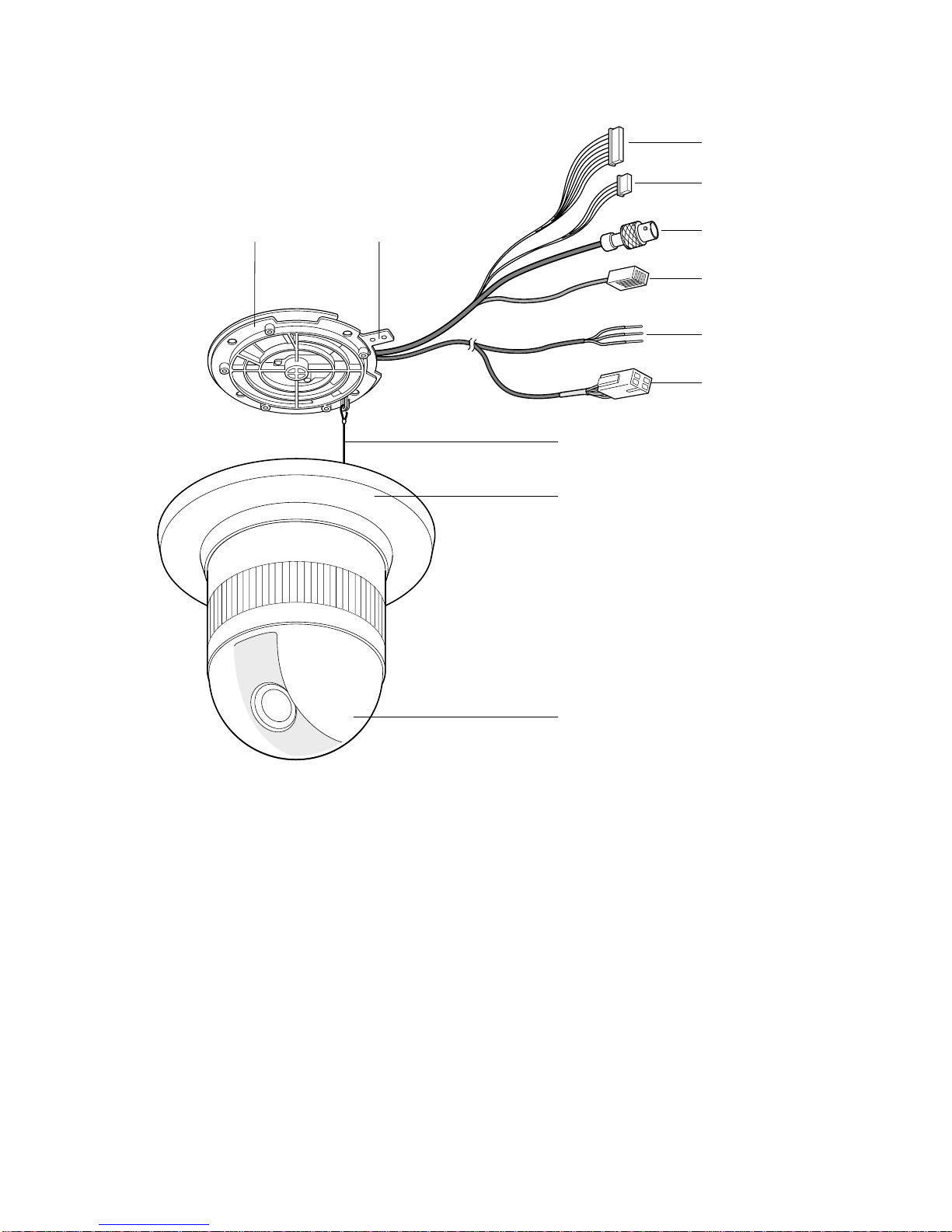
CONSTRUCTION
q Alarm Input Connector
w Alarm Output Connector
e Video Output Connector
r Data Port
t Power Cable(WV-CS850B)
t*Power Cable(WV-CS854BE)
y Camera Mounting Base
u Panning Start Point
i Fall Prevention Wire
o Decoration Cover
!0 Dome Cover
CONSTRUCTIONS
q
w
yu
e
r
t
(WV-CS850B)
t*
(WV-CS854BE)
i
o
!0

LIST OF CONSUMPTION PARTS
– 2-1 –
REF. NO. PART NAME LIFE
MO1 Pan Motor
MO2 Tilt Motor
MO3 Cooling Fan
* This is working all the time.
Equal to power on time.
M19 Lens (Focus Motor, Zoom Motor)
* Lens Motor itself is not supplied, but only
supplied as assembly.
M6 Slip Ring
8 Those figures are just for a reference under 35 ˚C environmental temperature and not for a guarantee.
It changes depending on the actual environment/operating condition.
8 Part numbers of these consumption parts are described in Replacement Parts List on page 7-1.
2.16 million PRESET actions
2.16 million AUTOPAN revolutions
(19,200 hours as 32 sec per a turn)
50,000 hours
Each 3.7 million actions
10 million PRESET actions
10 million AUTOPAN revolutions
(88,888 hours as 32 sec per a turn)
ADJUSTMENT PROCEDURE
1. Test Equipments Required
8
The following Test Equipments are required for
adjustment of the Combination Camera WVCS850B/CS854BE.
8
Oscilloscope
8
Frequency Counter
8
Digital Voltmeter
8
Vectorscope
8
Underscanned Colour Video Monitor
8
12 V DC Power Supply Unit
8
Lux Meter
8
Lighting (275 footcandles (2 750 lx), Colour Temperature
3 200 ˚K)
8
Personal Computer (IBM PC/AT type or equivalent)
8
Standard Straight RS-232C Cable
8
White Chart or White Paper
8
Radiation Chart
8
Colour Temperature Conversion Filters as shown in Table
1-1.
Table 1-1
8
Logarithmic Gray Scale Chart (Part No.: YWV2310RB99).
8
Colour Chip Chart (Part No.: YWV2100RB98).
8
System Controller such as WV-CU151 or WV-CU161.
8
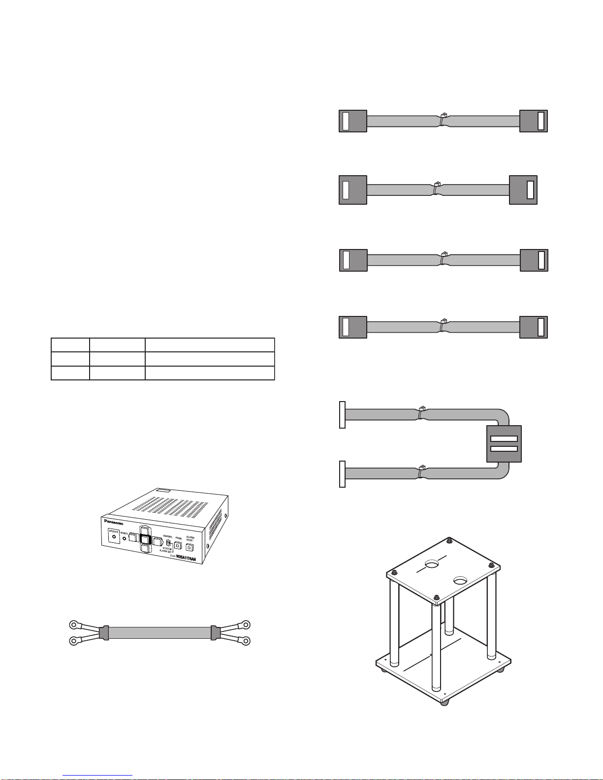
Electric Variable Resistor (E.V.R.) kit (Part No.:
YWV0EA1174AN) as shown in Fig. 1-1.
Fig. 1-1
8
Extension Cable for the Power Board and the Base Unit
(Part No.:V0EA1266AN) as shown in Fig. 1-2.
Fig. 1-2
8
Extension Board Ass'y A - D(Part No.: V0EA1265AN).
Extension Cable A for CN201 of the Main Board and
the Lens as shown in Fig. 1-3.
Fig. 1-3
Extension Cable B for CN4 of the Main Board and CN1
of the Servo Board as shown in Fig. 1-4.
Fig. 1-4
Extension Cable C for CN5 of the Servo Board and the
Pan Motor as shown in Fig. 1-5.
Fig. 1-5
Extension Cable C for CN2 of the Servo Board and the
Tilt Motor as shown in Fig. 1-6.
Fig. 1-6
Extension Cable D for CN1 and CN2 of the
Communication Board and the Base Unit as shown in
Fig. 1-7.
Fig. 1-7
8
CCD Mounting Adjustment Jig (Part No. : V0MA1120AN)
as shown in Fig. 1-8.
Fig. 1-8
– 2-2 –
Part No. Description
KODAK 80B change from 3 200 ˚K to 5 100 ˚K
KODAK 80B and 82C change from 3 200 ˚K to 6 500 ˚K
CN201CN4
CN5
CN2
CN1CN2
CN1
A
UP
C
D
A
C
B
UP
B
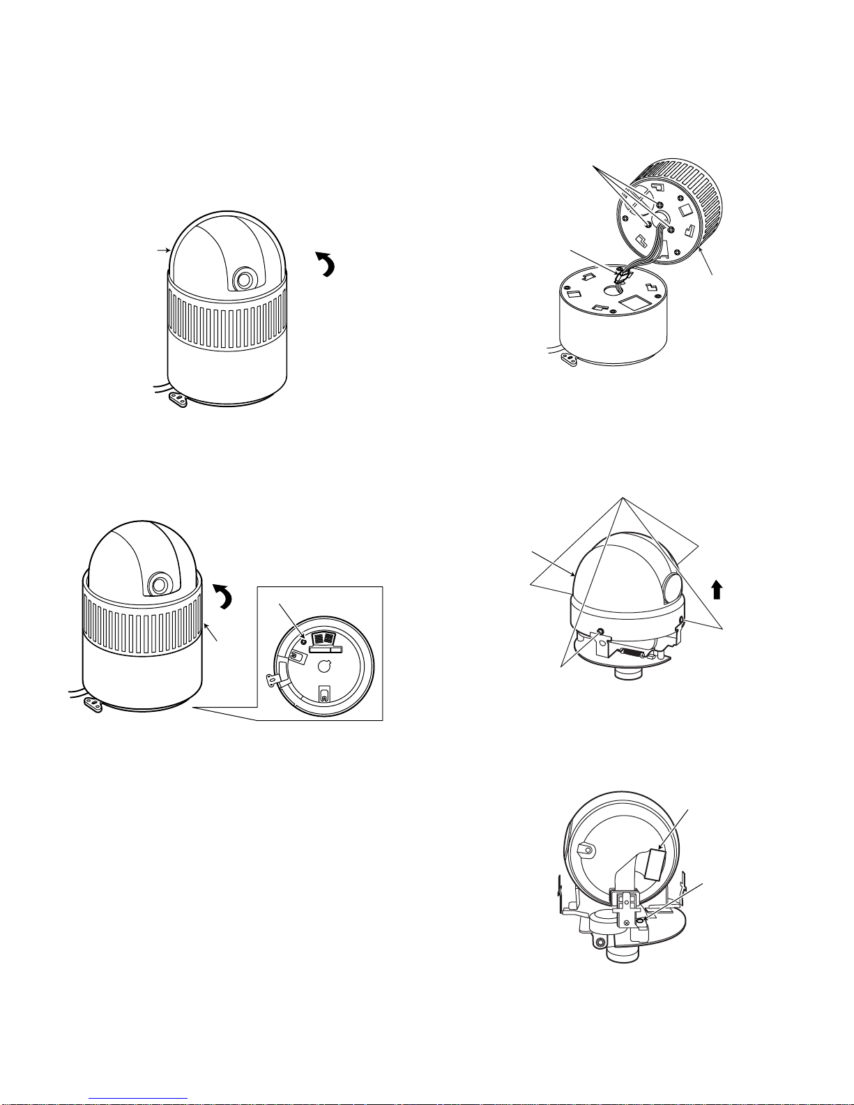
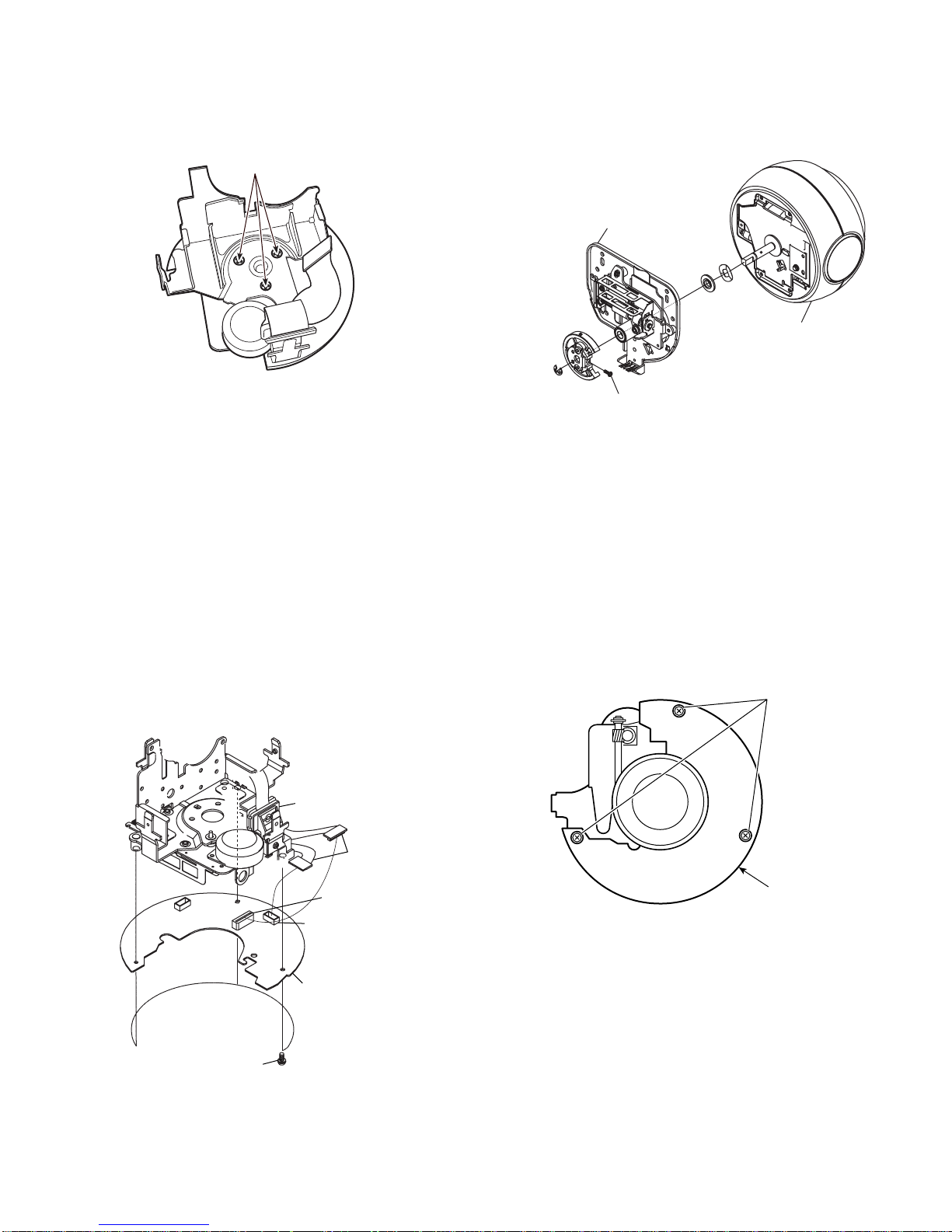
E Referring to Fig. 2-1-3, disconnect one connector, and
remove three screws that secure the Lower Diecast, and
remove the Lower Diecast Case.
Fig. 2-1-3
R Referring to Fig. 2-1-4, remove four screws that secure
the Inner Dome Cover and pull up the Inner Dome Cover.
Fig. 2-1-4
T Referring to Fig. 2-1-5, loosen one screw and disconnect
one connector.
Fig. 2-1-5
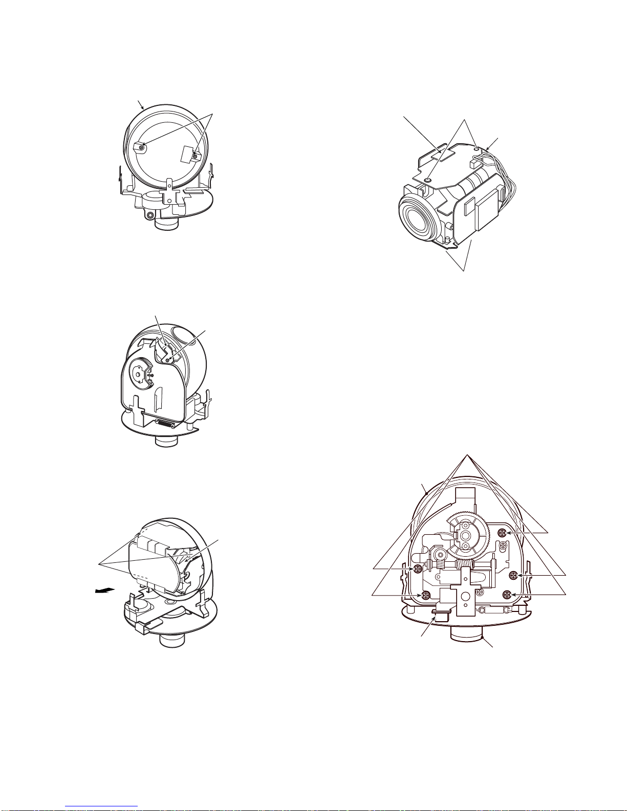
2. Disassembling Procedure
2.1. Disassembling Procedure for Camera
Head
Q Referring to Fig. 2-1-1, turn the Dome Cover to counter
clockwise direction, and remove the Dome Cover.
Fig. 2-1-1
W Referring to Fig. 2-1-2, remove one screw and turn the
Lower Diecast Case to the counterclockwise direction
and remove the Lower Diecast Case.
Fig. 2-1-2
– 2-3 –
Remove three screws.
Turn to
Dome Cover
counterclockwise.
Turn to counterclockwise.
Remove one screw.
Disconnect one connentor.
Lower Diecast
Case
Remove four screws.
Inner Dome
Cover
Lower
Diecast
Case
SW1 SW2
Disconnect one
connector.
Loosen one
screw.
O Referring to Fig. 2-1-9, remove four screws that secure
the Main Board and remove the Main Board and
disconnect one connector.
Fig. 2-1-9
2.2. Slip Ring Replacement Procedure
8 After disassembling the camera according to the "2.1
Disassembling Procedure for the Camera Head" Q -
T, carry out the following procedure.
Q Referring to Fig. 2-2-1, remove five screws and one
connector that secure the Camera Head Unit, and
remove the Camera Head Unit by pulling it up.
Fig. 2-2-1
Y Referring to Fig. 2-1-6, remove two screws that secure
the Lens Cover and remove the Lens Cover .
Fig. 2-1-6
U Referring to Fig. 2-1-7, remove one screw that secure the
Tilt Board.
Fig. 2-1-7
I Referring to Fig. 2-1-8, remove three screws that secure
the Camera Unit and remove the Camera Unit.
Fig. 2-1-8
– 2-4 –
Lens Cover
Remove
two screws.
Disconnect
one connector.
Remove two screws.
Main Board
Tilt Board
Remove one screw.
Camera Unit
Remove
three screws.
Remove two screws
Remove five screws.
Camera Head Unit
Remove one connector.
Slip Ring
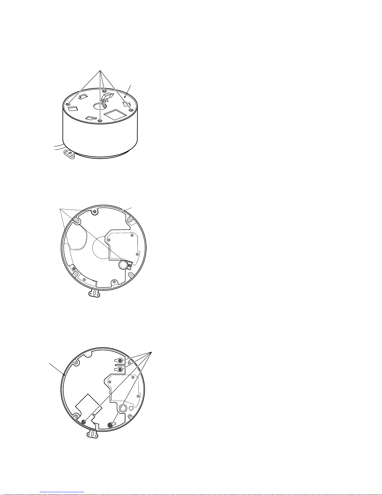
W Referring to Fig. 2-3-2, remove one screw that secure the
Tilt Chassis Ass'y and remove the Tilt Chassis Ass'y from
the Camera Unit.
Fig. 2-3-2
E Replace the Pan Chassis or the Tilt Chassis with new
one.
2.4. Power Board Replacement Procedure
8 After disassembling the camera according to "2.1.
Disassembling Procedure for the Camera Head" Q -
E, carry out the following procedure.
Q Referring to Fig. 2-4-1, remove three screws that secure
the Servo Board and remove the Servo Board.
Fig. 2-4-1
W Referring to Fig. 2-2-2, remove three screws that secure
the Slip Ring and remove the Slip Ring.
Fig. 2-2-2
E Replace the Slip Ring with new one.
2.3. Pan Chassis / Tilt Chassis
Replacement Procedure
8 After disassembling the camera according to "2.1.
Disassembling Procedure for the Camera Head" Q -
T and "2.2. Slip Ring Replacement Procedure" Q - E,
carry out the following procedure.
Q Referring to Fig. 2-3-1, remove three screws that secrure
the Servo Board and discconect the flexible cable from
the Servo Board CN9 and CN5, then remove the Servo
Board.
Fig. 2-3-1
– 2-5 –
Remove three screws.
Tilt Chassis Ass'y
Camera Unit
Pan Chassis Ass'y
Remove one screw.
Remove three screws.
CN5
Servo Board
Remove three screws.
Flexible Cable
CN9
Servo Board
W Referring to Fig. 2-4-2, remove four screws that secure
the Power Bottom Plate and remove the Power Bottom
Plate.
Fig. 2-4-2
E Referring to Fig. 2-4-3, remove three screws that secure
the Insulation Case and remove the Insulation Case.
Fig. 2-4-3
R Referring to Fig. 2-4-4, remove four screws that secures
the Power Board and remove the Power Board.
Fig. 2-4-4
– 2-6 –
Remove four screws
Power Bottom Plate
Remove three screws.
Insulation Case
Power Board
Remove four screws.
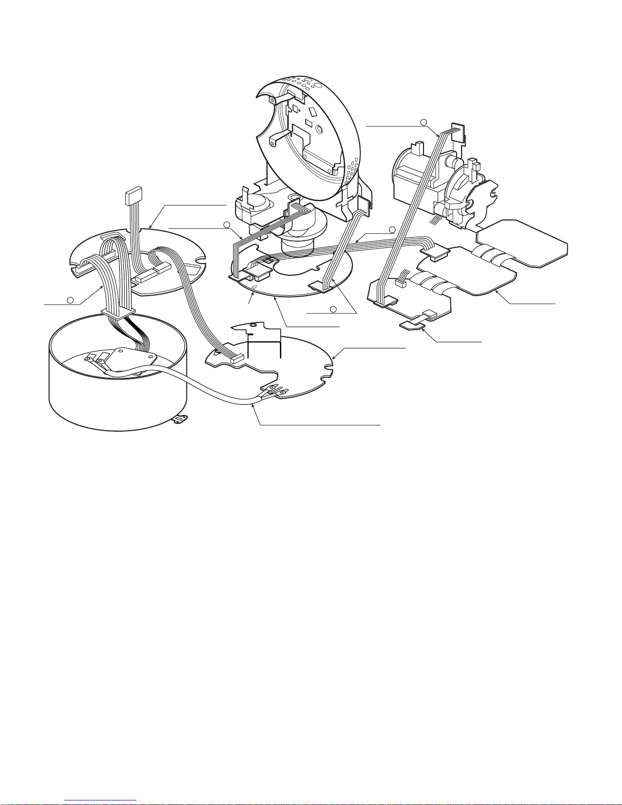
2.5. How to Connect the Extension Cables for Servicing
Fig. 2-5-1
8
Connect Extension Cable A between CN201 of the Main Board and the Lens.
8
Connect Extension Cable B between CN4 of the Main Board and CN1 of the Servo Board.
8
Connect Extension Cable C between CN5 of the Servo Board and the Pan Motor and between CN2 of the Servo Board and the
Tilt Motor.
8
Connect Extension Cable D between CN1 and CN2 of the Communication Board and the Base Unit.
8
Supply the power to WV-CS850B/CS854BE.
8
Contact the magnet to VS1 on the Servo Board.
– 2-7 –
Extension
Cable D
CN2
CN1
to Slip Ring
COMMUNICATION
BOARD
Extension Cable C
CN5
CN2
CN1
VS1
Extension Cable for the Power Board
and the Base Unit
Extension
Cable C
SERVO BOARD
Extension Cable
Extension
Cable B
POWER BOARD
CN201
A
CN4
MAIN BOARD
TILT BOARD
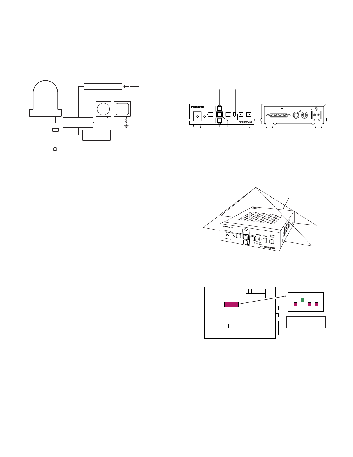
3. Connection and Setting up for
Adjustment
3.1. Connection
8
Fig. 3-1-1 shows the connecting diagram for the
adjustment of the WV-CS850B/CS854BE.
Fig. 3-1-1
8
Connect the Underscanned Colour Video Monitor to the
Video Output Connector of the E.V.R. Adjustment Kit
through the Vectorscope using the coaxial cables.
8
Connect the Video Output Cable of the WVCS850B/CS854BE to the CAMERA INPUT Connector of
the E.V.R. Adjustment Kit by the coaxial cable.
8
Terminate the input terminal of the Underscanned Colour
Video Monitor with 75Ω.
8
Connect the 24V AC Power Supply Unit to the WVCS854B or connect the 220-240 V AC Power Supply Unit
to the WV-CS850B.
8
Connect the +12 V DC Power Supply Unit to the E.V.R.
Adjustment Kit.
8
Connect the E.V.R. Adjustment Kit to IBM PC/AT type
using the Standard Straight RS-232C cable.
8
Connect the probe of the Digital Voltmeter, Oscilloscope
or Frequency Counter at the desired Test Point in each
adjustment step.
3.2. Setting Up for the Remote E.V.R
Adjustment Kit
< Remote E.V.R Adjustment Kit >
8
Fig. 3-2-1 shows the Remote E.V.R. Adjustment Kit.
Fig. 3-2-1
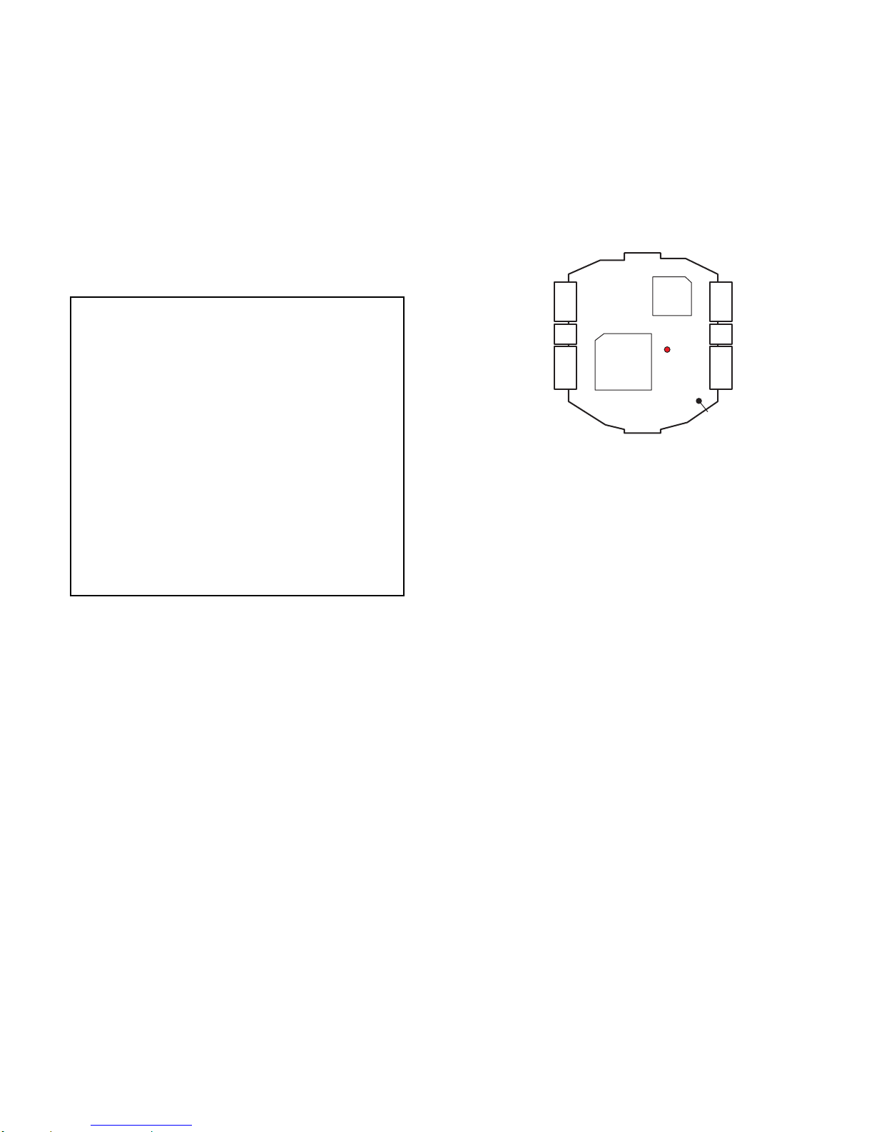
< Switch Setting >
8
Referring to Fig. 3-2-2, remove four screws that secure
the Upper Cover and remove the Upper Cover.
Fig. 3-2-2
8
Set the switch SW3 on the board to the position as shown
in Fig. 3-2-3.
Fig. 3-2-3
8
Set the VP/STD CAMERA selection switch on the rear
panel to STD CAMERA position.
– 2-8 –
Personal Computer
Underscanned
Colour Video Monitor
CAMERA
WV-CS850B
WV-CS854BE
24V AC
Power Supply
(for WV -CS854BE)
Standard
RS-232C
E.V.R.
Adjustment Kit
Vectorscope
+12V DC
Power Supply
220 - 240 V AC (for WV-CS850B)
Floppy Disk
75Ω
Mode Selection
Up
Switch
Switch
Left
Right
Switch
ALARM OFF
ALARM OFF
Set
Switch
NORMAL
NORMAL
SYSTEM
SYSTEM
Program
Switch
PROG
PROG
EVR
EVR
ALARM
ALARM
RESET
RESET
VP/STD Camera Selection Switch
STD. CAMERAVP CAMERA
RS232C
RS232C Connector
VIDEO CAMERA
DC12V IN
INOUT
OPERATE
OPERATE
REMOTE
REMOTE
Switch
Down
Switch
Remove four screws.
Upper Cover
<SW3>
ON
<Front>
SW3
<Rear>
1 2 3 4
Select switch #2 to
ON position.
Board

< Menu Setting >
8
Set the Mode Selection Switch on the Front Panel to the
"ALARM OFF"(center) position.
8
Keep pressing the Program Switch for 3 seconds or more
until "Program Menu" is displayed on the monitor screen.
8
Move the cursor to the "Controller Set Up" position by
pressing the Up and Down Switch.
8
Display the "Controller Set Up Menu" on the monitor by
pressing the Set Switch.
8
Move the cursor to the "Set Up Disable" position by
pressing the Up and Down Switch.
8
Change "Disable" to "Enable" by pressing the Set Switch.
8
After completing the above setting, move the cursor to
the Communication position by pressing the Up and
Down Switch.
8
Display the "Communication Menu" on the monitor by
pressing the Set Switch.
8
After confirming the Baud Rate is 9600, finish this menu
by pressing the Program Switch twice.
< Installing E.V.R Adjustment Program >
8
The Example given here is for A 2 drive computer, your
procedure might vary slightly depending on the drive
configuration.
8
Confirm that the contents of CONFIG.SYS file on your
computer is DEVICE=ANSI.SYS(Basic).
8
Insert floppy disk containing E.V.R. adjustment program
into your floppy drive (for example,drive:A) and type A:
8
At the prompt, type CD IBMPC and press ENTER key.
8
Type COPY RADJ2.EXE B: and press ENTER key.
8
Type CD\ and press ENTER key.
8
Type CD SEQ and press ENTER key.
8
Type COPY CS854BE.SEQ B: and press ENTER key.
8
Type COPY CS85BEAF.SEQ B: and press ENTER key.
8
Type COPY CS85BETL.SEQ B: and press ENTER key.
8
Type COPY CS85BEPR.SEQ B: and press ENTER key.
8
Type CD\ and press ENTER key.
8
Type CD EVR and press ENTER key.
8
Type COPY CS854BE.EV2 B: and press ENTER key.
8
After completing installation of program, you are ready to
use the E.V.R. adjustment program.
3.3. Setting Up for Standard Picture
8
The adjustment should be done after 30 minutes warm-up.
8
Set the Logarithmic Gray Scale Chart.
8
Incident light of 1 400 lx ± 50 lx on the Logarithmic Gray
Scale Chart.
8
Aim the Camera at the Logarithmic Gray Scale Chart.
8
Set the Camera by the E.V.R. Adjustment Kit so that the
Logarithmic Gray Scale Chart becomes full picture on the
Underscanned Colour Video Monitor.
8
Adjust the Lens Focus by the E.V.R. Adjustment Kit to
obtain correct focal point.
8
The adjustments should be done with this Standard
Picture, unless otherwise specified.
– 2-9 –
4. Adjustment Procedure
4.1 Camera Adjustment
4.1.1 Starting E.V.R. Adjustment Program
8 Insert new floppy disk containing DOS Operating System
and the E.V.R. Adjustment Program into IBM PC/AT and
turn on the IBM PC/AT.
8 At the prompt, type RADJ2 CS854BE and press the
ENTER key, then the initial menu page as shown in Fig. 4-
1-1 will be displayed.
Fig. 4-1-1
4.1.2. Saving the Adjustment Data
This saving procedure is recommended to keep the current
adjustment status of the camera.
8 Press the SAVE (F5) key of the computer, and the
computer will ask you for the file name.
8 Type xxxxxxxx.EV2 CC0 14CA. Give an appropriate file
name for xxxxxxxx within 8 letters, but do not use
CS854BE.
8 Press the ENTER key.
4.1.3. Loading the Adjustment Data
This loading procedure is recommended to return the
adjustment status of the camera to the factory default setting
or the setting you saved before.
8 Press the LOAD (F1) key of the computer, and the
computer will ask you for the file name.
8 Type CS854BE.EV2 or xxxxxxxx.EV2 (xxxxxxxx means
a file name you named before.) and press the ENTER
key.
4.1.4. Adjustment Procedure
8 Select the item "1. SC FREQUENCY" with the ARROW
key and press the ENTER key.
(1) Subcarrier Frequency Adjustment for INT mode
Test Point: TD4 (SC VCXO)
8 Connect the Frequency Counter to TD4 as shown in Fig.
4-1-2.
Fig. 4-1-2
8 Adjust the data with the ARROW key so that the
Subcarrier Frequency becomes 17.734 47 MHz ± 40 Hz.
8 Press the ENTER key for the next adjustment.
(2) Subcarrier Frequency Adjustment for LL mode
Test Point: TD4 (SC VCXO)
8 Connect the Frequency Counter to TD4 as shown in Fig.
4-1-2.
8 Adjust the data with the ARROW key so that the
Subcarrier Frequency becomes 17.734 47 MHz ± 40 Hz.
8 Press the ENTER key for the next adjustment.
(3) Line Lock Phase Adjustment
Test Point: Video Output Connector
AC Live Waveform
8 Connect the CH1 of the Oscilloscope to the Video Output
Connector.
8 Connect the CH2 of the Oscilloscope to the AC Power
Line.
8 Trigger the Oscilloscope at V-rate.
8 Adjust data with the ARROW keys so that the decay point
of V-sync signal gains 2H ± 4H from the zero-cross point
of the AC Power Line Input Waveforms as shown in Fig.
4-1-3.
– 2-10 –
PANASONIC EVR ADJUSTMENT SYSTEM (C)MCI Co. CCTV PRODUCT: CS850 EEPROM: 0
∗∗∗∗∗∗∗∗∗∗∗∗∗∗∗∗∗∗∗∗∗∗∗∗∗∗∗∗∗∗∗∗∗∗∗∗∗∗∗∗∗∗∗∗∗∗∗∗∗∗∗∗∗∗∗∗∗∗∗∗∗∗∗∗
1. SC FREQUENCY
2. SC FREQUENCY
3.1. LL PHASE1 FOR AC type (50Hz)
3.2. LL PHASE2 FOR AC type (50Hz)
5. HI CLIP LEVEL
6. PEDESTAL
7. ALC DC
8.1. VIDEO OUT GAIN (L)
8.2. VIDEO OUT GAIN (H)
9.1. BURST LEVEL R
9.2. BURST LEVEL B
9.3. BURST PHASE R
9.4. BURST PHASE B
10.1. WB 3200K MANU OFFSET R
10.2. WB 3200K MANU OFFSET B
11.1. WB 6500K ATW LIMIT R
11.2. WB 6500K ATW LIMIT B
12.1. 3200K R_GAIN
12.2. 3200K B_GAIN
12.3. 3200K R_PHASE
<CONTENTS> TD4 17.73447+–40Hz
<INSTRUCTION> PLEASE CHOOSE MENU DATA BY ARROW-KEY
LOAD(F1) QUIT(F3) SAVE(F5)
MENU
Page (1/1)
12.4. 3200K B_PHASE
13.1. 5100K R_GAIN
13.2. 5100K B_GAIN
13.3. 5100K R_PHASE
13.4. 5100K B_PHASE
14. HIGHLIGHT CHROMA CLIP
NTSC
TD4
Main Board
(Digital Section)
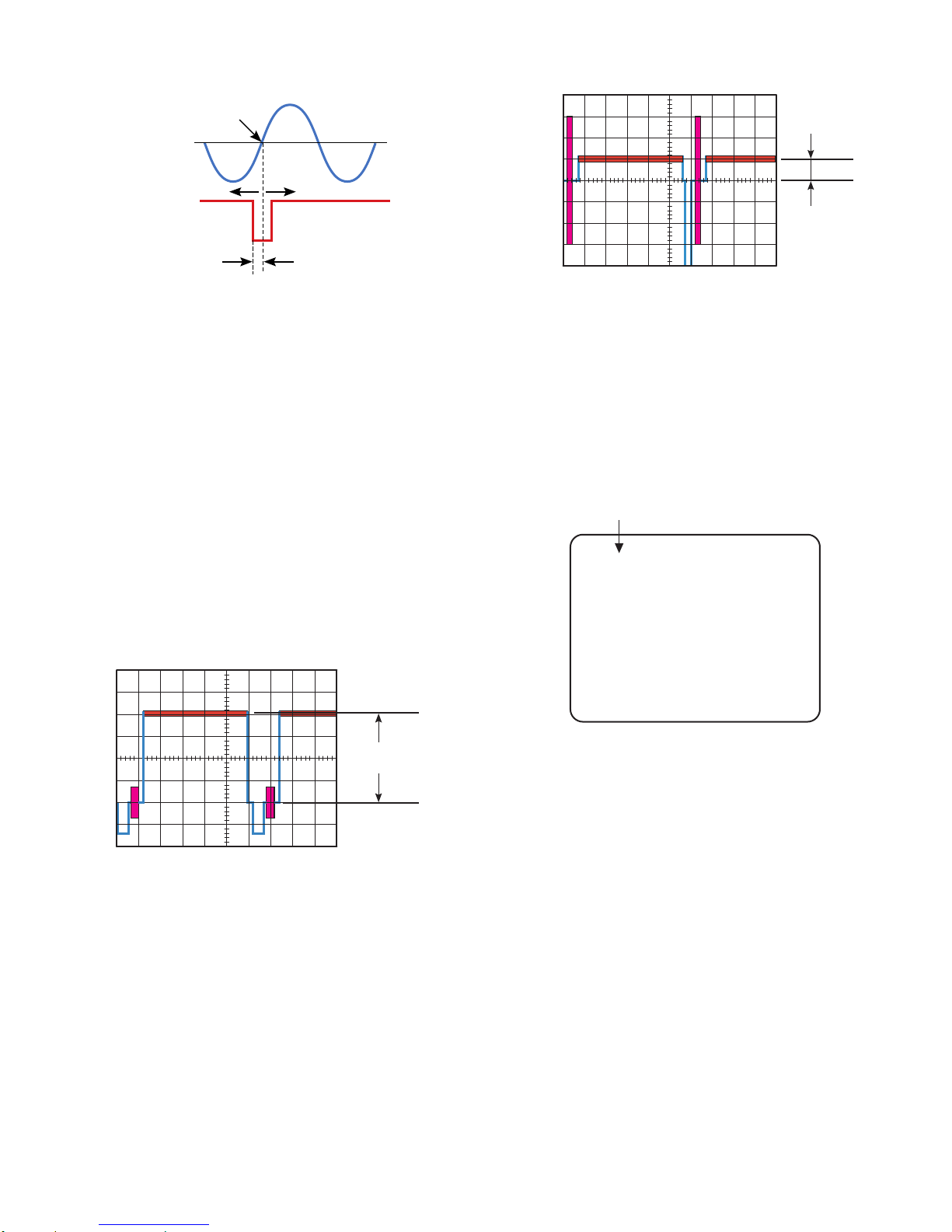
Fig. 4-1-3
8 Press the ENTER key for the next adjustment.
8 Adjust data with the ARROW keys so that the decay point
of V-sync signal gains 2H ± 4H from the zero-cross point
of the AC Power Line Input Waveforms as shown in Fig.
4-1-3.
8 Press the ENTER key for the next adjustment.
(5) High Clip Level Adjustment
Test Point: Video Output Connector
8 Aim the Camera at the Logarithmic Grayscale Chart.
8 Connect the terminated Oscilloscope with 75Ω to the
Video Output Connector.
8 Trigger the Oscilloscope at H-rate.
8 Adjust data with the ARROW keys so that the High Clip
Level becomes 790 mV ± 30 mV as shown in Fig. 4-1-4.
Fig. 4-1-4
8 Press the ENTER key for the next adjustment.
(6) Pedestal Adjustment
Test Point: Video Output Connector
8 Connect the terminated Oscilloscope with 75Ω to the
Video Output Connector.
8 Adjust data with the ARROW keys so that the Pedestal
level becomes 50 mV ± 5 mV as shown in Fig. 4-1-5.
Fig. 4-1-5
8 Press the ENTER key for the next adjustment.
(7) ALC DC Level Adjustment
Observe: Video Monitor
8 Aim the Camera at the Logarithmic Grayscale Chart.
8 Adjust data with the ARROW keys so that the second data
from left becomes between 00 and 05 on the Video
Monitor as shown in Fig. 4-1-6.
Fig. 4-1-6
8 Press the ENTER key for the next adjustment.
(8) Video Out Gain Adjustment
Test Point: Video Output Connector
8 Aim the Camera at the Logarithmic Grayscale Chart.
8 Connect the terminated Oscilloscope with 75Ω to the
Video Output Connector.
8 Adjust data with the ARROW keys so that the Video
Output signal level becomes 700 mV ± 50 mV as shown in
Fig. 4-1-7.
AC Line Input
– 2-11 –
Waveform
Zero-Cross Point
Video Output
Signal Waveform
– +
V SYNC
2H ± 4H
50 mV ± 10 mV
Second data becomes between 00 and 05.
00 00 00 00 1C 10 88 30
790 mV ± 30 mV
(Data are just example.)
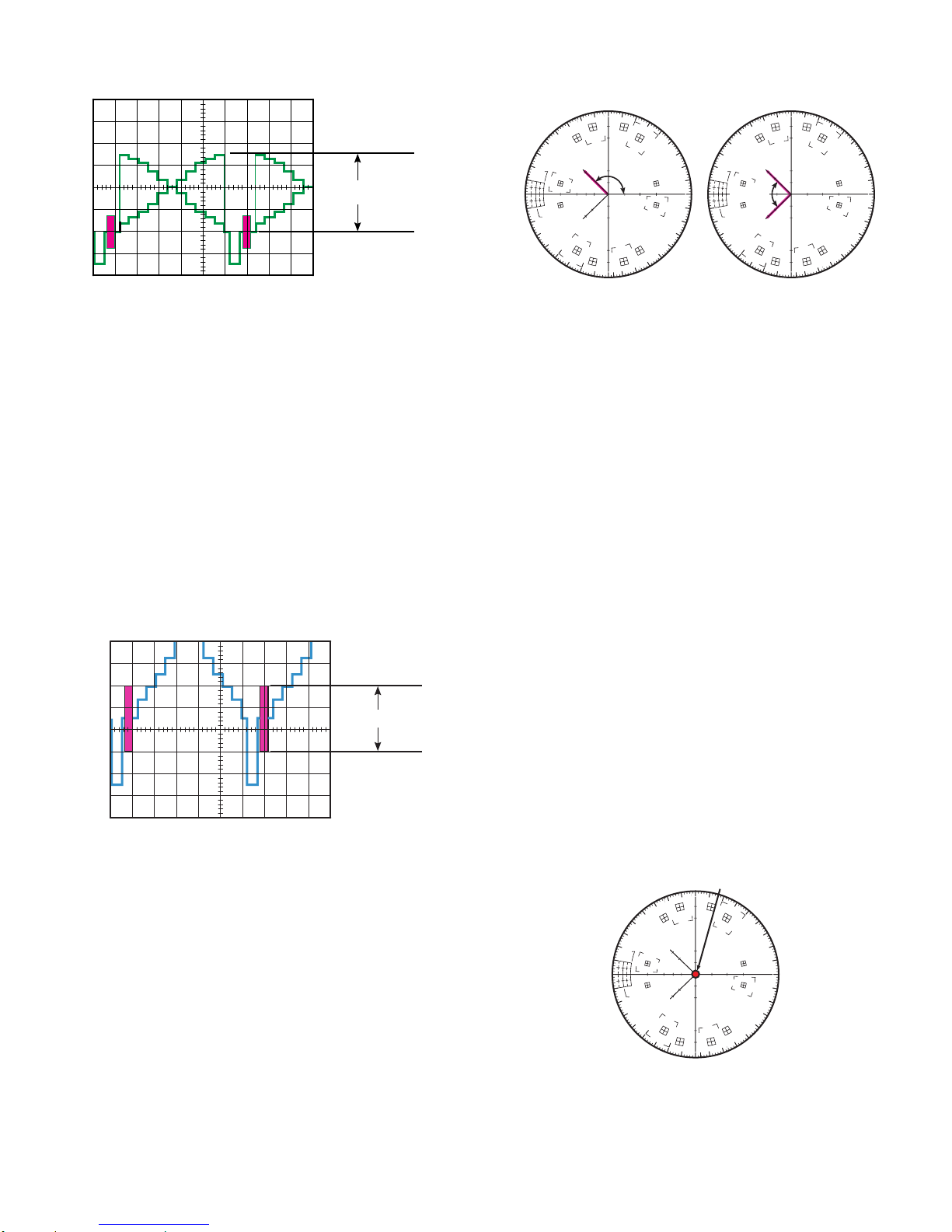
Fig. 4-1-7
8 Press the ENTER key for the next adjustment.
8 Adjust data with the ARROW keys so that the Video
Output signal level becomes 700 mV ± 50 mV as shown in
Fig. 4-1-7.
8 Press the ENTER key for the next adjustment.
(9) Burst Level and Phase Adjustment
Test Point: Video Output Connector
8 Aim the Camera at the Logarithmic Grayscale Chart.
8 Connect the terminated Oscilloscope with 75Ω to the
Video Output Connector.
8 Adjust data with the ARROW keys so that the Burst signal
level becomes 300 mV ± 10 mV as shown in Fig. 4-1-8.
Fig. 4-1-8
8 Press the ENTER key for the next adjustment.
8 Adjust data with the ARROW keys so that the Burst signal
level becomes 300 mV ± 10 mV as shown in Fig. 4-1-8.
8 Press the ENTER key for the next adjustment.
8 Set the Mode Switch of the Vectorscope to "NTSC" mode.
8 Adjust data with the ARROW keys so that the Burst Phase
becomes 135˚ ±1˚ as shown in Fig. 4-1-9.
Fig. 4-1-9
8 Set the Mode Switch of the Vectorscope to "PAL" mode.
8 Adjust data with the ARROW keys so that the Burst Phase
becomes 90˚ ±2˚ as shown in Fig. 4-1-9.
8 Press the ENTER key for the next adjustment.
8 Set the Mode Switch of the Vectorscope to "NTSC" mode.
8 Adjust data with the ARROW keys so that the Burst Phase
becomes 135˚ ±1˚ as shown in Fig. 4-1-9.
8 Set the Mode Switch of the Vectorscope to "PAL" mode.
8 Adjust data with the ARROW keys so that the Burst Phase
becomes 90˚ ±2˚ as shown in Fig. 4-1-9.
8 Select "9.1. BURST LEVEL R" with the ROLLDOWN key.
8 Repeat this adjustment (9) until both Burst Level and
Phase are adjusted to proper position as shown in Fig. 41-8 and Fig. 4-1-9.
8 Press the ENTER key for the next adjustment.
(10.1) White Balance 3200 ˚K Manual Offset R
Adjustment
Test Point: Video Output Connector
8 Set the gain control of the Vectorscope to maximum.
8 Aim the Camera at the White Chart or the White Paper.
8 Adjust data with the ARROW key so that the vector
positions at the center of the Vectorscope as shown in Fig.
4-1-10.
Fig. 4-1-10
8 Press the ENTER key for the next adjustment.
700 mV ± 50 mV
– 2-12 –
NTSC mode PAL mode
cy
g
R
dø
20%
75%
YL
dG
10°
0°
10°
20%
dG
100%
yl
G
r
V
135 ± 1 °
CY
MG
dø
b
10°
U
0°
B
10°
mg
20%
dG
20%
dG
g
YL
90 ± 2 °
yl
G
cy
R
75%
100%
r
MG
V
b
U
B
CY
mg
300 mV ± 10 mV
Positions at center.
cy
g
R
dø
20%
75%
YL
dG
10°
0°
10°
20%
dG
100%
yl
G
r
MG
V
b
U
B
CY
mg
 Loading...