

Page 1

Digital Disk Recorder
Installation Guide
Model Nos. WJ-RT416
WJ-RT416V
WJ-RT416 is shown above.
Before attempting to connect or operate this product,
please read these instructions carefully and save this manual for future use.
No model number suffix is shown in this Operating Instructions.
SEQ
U
EN
H
D
C
D
E
1
E
R
R
O
R
A
LAR
M
T
IMER
O
PER
A
TE
1
2
M
U
S
C
3
R
4
5
A
R
6
2
3
L
TI
E
E
N
5
9
L
A
R
M
E
S
E
T
1
3
4
6
7
8
1
0/0
11
1
2
1
4
15
16
SEARCH
S
E
T
UP
CO
P
Y
ESC
S
E
T
ST
O
P
PLA
Y
P
A
U
S
E
R
E
C
REV
FWD
R
SK
I
P
Digital Disk R
EC STOP
ecorder WJ-RT41
6
Page 2
2
FOR YOUR SAFETY PLEASE READ THE FOLLOWING TEXT CAREFULLY.
This appliance is supplied with a moulded three pin mains plug for your
safety and convenience.
A 5 amp fuse is fitted in this plug.
Should the fuse need to be replaced please ensure that the replacement
fuse has a rating of 5 amp and that it is approved by ASTA or BSI to
BS1362.
Check for the ASTA mark
H or the BSI mark G on the body of the
fuse.
If the plug contains a removable fuse cover you must ensure that it is
refitted when the fuse is replaced.
If you lose the fuse cover the plug must not be used until a replacement
cover is obtained.
A replacement fuse cover can be purchased from your local Panasonic
Dealer.
IF THE FITTED MOULDED PLUG IS UNSUITABLE FOR THE SOCKET OUTLET IN YOUR HOME THEN THE FUSE SHOULD BE
REMOVED AND THE PLUG CUT OFF AND DISPOSED OF SAFELY.
THERE IS A DANGER OF SEVERE ELECTRICAL SHOCK IF THE
CUT OFF PLUG IS INSERTED INTO ANY 13 AMP SOCKET.
If a new plug is to be fitted please observe the wiring code as shown
below.
If in any doubt please consult a qualified electrician.
WARNING: This apparatus must be earthed.
IMPORTANT
The wires in this mains lead are coloured in accordance with the following code.
Green-and-yellow: Earth
Blue: Neutral
Brown: Live
As the colours of the wire in the mains lead of this appliance may not
correspond with the coloured markings identifying the terminals in your
plug, proceed as follows.
The wire which is coloured green-and-yellow must be connected to
the terminal in the plug which is marked with the letter E or by the earth
symbol
I or coloured green or green-and-yellow.
The wire which is coloured blue must be connected to the terminal in
the plug which is marked with the letter N or coloured black.
The wire which is coloured brown must be connected to the terminal
in the plug which is marked with the letter L or coloured red.
How to replace the fuse
Open the fuse compartment with
a screwdriver and replace the fuse
and fuse cover.
For U.K.
The lightning flash with arrowhead symbol,
within an equilateral triangle, is intended to
alert the user to the presence of uninsulated
"dangerous voltage" within the product's
enclosure that may be of sufficient magnitude to constitute a risk of electric shock to
persons.
The exclamation point within an equilateral
triangle is intended to alert the user to the
presence of important operating and maintenance (servicing) instructions in the literature accompanying the appliance.
Power disconnection. Unit with or without
ON-OFF switches have power supplied to
the unit whenever the power cord is inserted
into the power source; however, the unit is
operational only when the ON-OFF switch is
in the ON position. Unplug the power cord to
disconnect the main power for all units.
FUSE
CAUTION: TO REDUCE THE RISK OF ELECTRIC SHOCK,
DO NOT REMOVE COVER (OR BACK).
NO USER-SERVICEABLE PARTS INSIDE.
REFER SERVICING TO QUALIFIED SERVICE PERSONNEL.
CAUTION
RISK OF ELECTRIC SHOCK
DO NOT OPEN
WARNING:
• This apparatus must be earthed.
• Apparatus shall be connected to a mains socket outlet with a
protective earthing connection.
• The mains plug or an appliance coupler shall remain readily
operable.
• To prevent fire or electric shock hazard, do not expose this
apparatus to rain or moisture.
• The apparatus should not be exposed to dripping or splashing
and that no objects filled with liquids, such as vases, should be
placed on the apparatus.
• All work related to the installation of this product should be
made by qualified service personnel or system installers.
• The connections should comply with local electrical code.
CAUTION:
Before attempting to connect or operate this product, please
read the label on the bottom.
We declare under our sole responsibility that the product to which this
declaration relates is in conformity with the standards or other normative
documents following the provisions of Directives 2006/95/EC and
2004/108/EC.
Nosotros declaramos bajo nuestra única responsabilidad que el
producto a que hace referencia esta declaración está conforme con las
normas u otros documentos normativos siguiendo las estipulaciones de
las directivas 2006/95/CE y 2004/108/CE.
Noi dichiariamo sotto nostra esclusiva responsabilità che il prodotto a
cui si riferisce la presente dichiarazione risulta conforme ai seguenti
standard o altri documenti normativi conformi alle disposizioni delle
direttive 2006/95/CE e 2004/108/CE.
Wir erklären in alleiniger Verantwortung, daß das Produkt, auf das sich
diese Erklärung bezieht, mit der folgenden Normen oder normativen
Dokumenten übereinstimmt. Gemäß den Bestimmungen der Richtlinie
2006/95/EC und 2004/108/EC.
Nous déclarons sous note seule responsabilité que le produit auquel se
réfère la présente déclaration est conforme aux normes ou autres
documents normatifs conformément aux dispositions des directives
2006/95/CE et 2004/108/CE.
Wij verklaren als enige aansprakelijke, dat het product waarop deze
verklaring betrekking heeft, voldoet aan de volgende normen of andere
normatieve documenten, overeenkomstig de bepalingen van Richtlijnen
2006/95/EC en 2004/108/EC.
Vi erklærer os eneansvarlige for, at dette produkt, som denne
deklaration omhandler, er i overensstemmelse med standarder eller
andre normative dokumenter i følge bestemmelserne i direktivene
2006/95/EC og 2004/108/EC.
Vi deklarerar härmed värt fulla ansvar för att den produkt till vilken
denna deklaration hänvisar är i överensstämmelse med
standarddokument, eller andra normativa dokument som framställs i
direktiv nr. 2006/95/EC och 2004/108/EC.
Ilmoitamme yksinomaisella vastuullamme, että tuote, jota tämä ilmoitus
koskee, noudattaa seuraavia standardeja tai muita ohjeellisia asiakirjoja,
jotka noudattavat direktiivien 2006/95/EC ja 2004/108/EC säädöksiä.
Vi erklærer oss alene ansvarlige for at produktet som denne erklæringen
gjelder for, er i overensstemmelse med følgende normer eller andre
normgivende dokumenter som følger bestemmelsene i direktivene
2006/95/EC og 2004/108/EC.
Page 3

3
The serial number of this product may be found on the surface of the unit.
You should note the serial number of this unit in the space
provided and retain this book as a permanent record of your
purchase to aid identification in the event of theft.
Model No.
Serial No.
NOTE: This equipment has been tested and found to comply with the limits for a Class A digital device, pursuant to
Part 15 of the FCC Rules. These limits are designed to provide reasonable protection against harmful interference
when the equipment is operated in a commercial environment. This equipment generates, uses, and can radiate
radio frequency energy and, if not installed and used in
accordance with the instruction manual, may cause harmful
interference to radio communications.
Operation of this equipment in a residential area is likely to
cause harmful interference in which case the user will be
required to correct the interference at his own expense.
FCC Caution: To assure continued compliance, (example use only shielded interface cables when connecting to computer or peripheral devices). Any changes or modifications
not expressly approved by the party responsible for compliance could void the user’s authority to operate this equipment.
For U.S.A
This Class A digital apparatus complies with Canadian
ICES-003.
For Canada
Important Notice: (for U.S. fileds only)
This product contains a CR Coin Cell Lithium Battery
which contains Perchlorate Material - special handling
may apply.
See www.dtsc.ca.gov/hazardouswaste/perchlorate.
CLASS 1 LASER PRODUCT
Page 4

4
Limitation of liability
THIS PUBLICATION IS PROVIDED "AS IS" WITHOUT WARRANTY OF ANY KIND, EITHER EXPRESS OR IMPLIED,
INCLUDING BUT NOT LIMITED TO, THE IMPLIED WARRANTIES OF MERCHANTABILITY, FITNESS FOR ANY PARTICULAR PURPOSE, OR NON-INFRINGEMENT OF THE
THIRD PARTY’S RIGHT.
Disclaimer of warranty
IN NO EVENT SHALL MATSUSHITA ELECTRIC INDUSTRIAL CO., LTD. BE LIABLE TO ANY PARTY OR ANY PERSON, EXCEPT FOR REPLACEMENT OR REASONABLE
MAINTENANCE OF THE PRODUCT, FOR THE CASES,
INCLUDING BUT NOT LIMITED TO BELOW:
(1) ANY DAMAGE AND LOSS, INCLUDING WITHOUT LIM-
ITATION, DIRECT OR INDIRECT, SPECIAL, CONSEQUENTIAL OR EXEMPLARY, ARISING OUT OF OR
RELATING TO THE PRODUCT;
(2) PERSONAL INJURY OR ANY DAMAGE CAUSED BY
INAPPROPRIATE USE OR NEGLIGENT OPERATION
OF THE USER;
(3) UNAUTHORIZED DISASSEMBLE, REPAIR OR MODIFI-
CATION OF THE PRODUCT BY THE USER;
(4) ANY PROBLEM, CONSEQUENTIAL INCONVENIENCE,
OR LOSS OR DAMAGE, ARISING OUT OF THE SYSTEM COMBINED BY THE DEVICES OF THIRD PARTY;
(5) ANY CLAIM OR ACTION FOR DAMAGES, BROUGHT
BY ANY PERSON OR ORGANIZATION BEING A PHOTOGENIC SUBJECT, DUE TO VIOLATION OF PRIVACY
WITH THE RESULT OF THAT SURVEILLANCE-CAMERA’S PICTURE, INCLUDING SAVED DATA, FOR SOME
REASON, BECOMES PUBLIC OR IS USED FOR THE
PURPOSE OTHER THAN SURVEILLANCE.
THIS PUBLICATION COULD INCLUDE TECHNICAL INACCURACIES OR TYPOGRAPHICAL ERRORS. CHANGES
ARE ADDED TO THE INFORMATION HEREIN, AT ANY
TIME, FOR THE IMPROVEMENTS OF THIS PUBLICATION
AND/OR THE CORRESPONDING PRODUCT (S).
Page 5

5
Important safety instructions
1) Read these instructions.
2) Keep these instructions.
3) Heed all warnings.
4) Follow all instructions.
5) Do not use this apparatus near water.
6) Clean only with dry cloth.
7) Do not block any ventilation openings. Install in accordance with the manufacturer's instructions.
8) Do not install near any heat sources such as radiators, heat registers, stoves, or other apparatus (including amplifiers) that
produce heat.
9) Do not defeat the safety purpose of the polarized or grounding-type plug. A polarized plug has two blades with one wider
than the other. A grounding type plug has two blades and a third grounding prong. The wide blade or the third prong are
provided for your safety. If the provided plug does not fit into your outlet, consult an electrician for replacement of the
obsolete outlet.
10) Protect the power cord from being walked on or pinched particularly at plugs, convenience receptacles, and the point
where they exit from the apparatus.
11) Only use attachments/accessories specified by the manufacturer.
12) Use only with the cart, stand, tripod, bracket, or table specified by the manufacturer, or sold with the apparatus. When a
cart is used, use caution when moving the cart/apparatus combination to avoid injury from tip-over.
13) Unplug this apparatus during lightning storms or when unused for long periods of time.
14) Refer all servicing to qualified service personnel. Servicing is required when the apparatus has been damaged in any way,
such as power-supply cord or plug is damaged, liquid has been spilled or objects have fallen into the apparatus, the
apparatus has been exposed to rain or moisture, does not operate normally, or has been dropped.
S3125A
Page 6

6
CONTENTS
Limitation of liability ........................................................... 4
Disclaimer of warranty ...................................................... 4
Important safety instructions ............................................. 5
Precautions ....................................................................... 7
Preface ............................................................................. 9
Features ............................................................................ 9
About these operating instructions ................................... 10
Trademarks and registered trademarks ............................ 10
Major operating controls and their functions ..................... 11
■ Front View ................................................................... 11
■ Rear View ................................................................... 13
Image display ................................................................. 15
Startup .............................................................................. 16
Adjustment of the clock of the recorder ............................ 17
Shutdown of the recorder ................................................. 18
Monitor live images from the cameras .............................. 19
Display images on a single screen ................................. 19
Display images from cameras on a multi-screen ............ 19
Display images from the cameras sequentially
(sequential display) ......................................................... 20
Recording ......................................................................... 21
Manual recording ............................................................ 21
Timer recording .............................................................. 21
Alarm recording .............................................................. 21
Playback ........................................................................... 22
Search and play ................................................................ 24
Start playback by designating the desired time and date
of recorded images to be played .................................... 24
Search and play with multiple search filters ................... 25
Alarm function ................................................................... 27
Action at an event occurrence (alarm action) ................. 27
Cancel the alarm action .................................................. 28
Copying (Duplicate) .......................................................... 29
Log in as a different user .................................................. 31
Log out ............................................................................ 31
Log in .............................................................................. 32
Disk management ............................................................. 33
Check HDD information .................................................. 33
Format the HDD ............................................................. 35
Operate the recorder using a PC ...................................... 38
Functions and their descriptions ..................................... 38
System requirements for a PC ....................................... 38
Installation ......................................................................... 39
HDD safety mode ........................................................... 39
Operating the recorder for the first time .......................... 39
Installation ...................................................................... 39
HDD replacement ............................................................. 40
HDD addition .................................................................. 40
Rack mounting .................................................................. 41
Connection ........................................................................ 42
Basic connection ............................................................ 42
Connection with RS485 cameras ................................... 43
Connection with PS·Data systems ................................. 44
Connection with a PC ..................................................... 46
DIP Switch Setting .......................................................... 47
RS485 (CAMERA) port ................................................... 49
AUDIO IN/ALARM OUT terminal .................................... 49
ALARM IN/CONTROL terminal ....................................... 50
Setup menu ...................................................................... 51
Setup menu chart ........................................................... 51
Basic operation of the setup menu ................................. 52
Configure the system settings [System Setup] ............... 53
Configure the recording settings [Recording Setup] ....... 55
Configure the alarm action settings [Event Setup] ......... 58
Configure the display settings [Display Setup] ............... 61
Configure the settings relating to the camera control
[Camera Control Setup] .................................................. 62
Configure the settings relating to communications with
other devices [Communication Setup] ............................ 63
Configure the settings relating to user information
[User Management] ........................................................ 66
Maintenance functions [Maintenance] ............................ 68
Operation using the system controller .............................. 73
Troubleshooting ................................................................ 75
Specifications .................................................................... 78
Standard accessories ....................................................... 79
Recording time length ....................................................... 79
Page 7
7
Precautions
Refer all work related to the installation of this product
to qualified service personnel or system installers.
When the model in use is the NTSC model, connect the
unit to a 120 V AC power source.
When the model in use is the PAL model, connect the
unit to a 220 - 240 V AC power source.
Do not connect this unit to an outlet to which appliances
with high power consumption such as an air conditioning or
a copy machine is already being connected.
Do not operate the unit beyond its specified temperature, humidity, or power source ratings.
Use the unit at temperatures between 5 °C - 45 °C {41 °F 113 °F} and where the humidity is between 5 % - 90 %.
Performance and lifetime of hard disk drives are easily
affected by heat (used at high temperature) characteristically. It is recommended to use this unit at temperatures
between 20 °C - 30 °C {68 °F - 86 °F}.
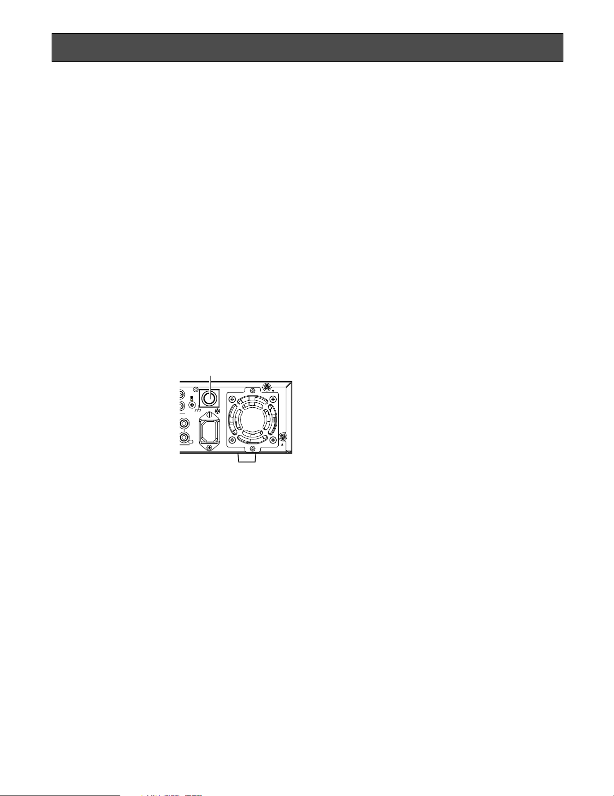
POWER button
The POWER button is located on the rear of the unit. Even
though the POWER button is set to "OFF", the power supply
will not be cut. To cut the
power supply, unplug the
power plug of the unit from
the AC outlet. When using
the power supply control
unit, turn off the power of
the power supply control
unit.
Built-in backup battery
The built-in battery life is approximately 5 years as an indication of replacement. (This is just an indication of replacement. We are not providing any guarantee of the built-in
battery lifetime. Replacement cost of the built-in battery is
not covered by the warranty even if it needs to be done
within the warranty period.) When reaching the end of its
lifetime, the time and date setting will not be saved after the
power of the unit is turned off. Ask the shop where you purchased the unit when replacement of the battery is
required.
Built-in hard disk drives
Hard disk drives are vulnerable to vibration. Handle them
with care.
It is possible to damage them if they are moved while their
motors are still running. Do not move them just after turning
their power on or off (for around 30 seconds).
A lifetime of hard disk drives is limited by use.
It is recommended to replace them after around 18 000
hours of operation to prevent data loss from disk failures.
Write error may occur frequently after around 20 000 hours
of operation and the head and motor deterioration may
occur and will reach their lifetime after 30 000 hours of
operation when they have been used at the recommended
ambient temperature (approx. 25 °C {77 °F}).
When hard disk drive trouble occurs, replace it immediately. Consult your dealer for servicing.
When replacing the hard disk drives, take notice of the following.
• Protect the hard disk drives from static electricity.
• Do not stack them, or keep them upright.
• Do not use an electric screwdriver to fix them.
(Tightening torque: Approx. 0.49 N·m {5 kgf·cm})
• Avoid rapid changes of the temperature/humidity to
prevent condensation.
(Acceptable change: within 15 °C/h {59 °F/h})
Avoid the following locations for installation.
• Places exposed to direct water, moisture, or sunlight
directly
• Places subject to having strong vibration or impact
• Near magnetic field sources such as a television or
speakers, magnet, etc.
• Steamy and oily places such as kitchens
• Places which are not level
• Place where condensation forms easily, where temperature changes greatly
Place the recorder horizontally on a level surface.
Do not place the recorder in an upright position. When
stacking multiple recorders, clear a space of more than 5
cm from both sides, the top, the bottom and the rear of the
recorders.
Heat dissipation
Refer to the following to prevent fire and malfunction of the
recorder.
• Do not block the ventilation openings in the cover to
prevent the recorder from overheating. Maintain the
recorder periodically to prevent dust from blocking
openings.
• A lifetime of the cooling fan is limited by use. Contact
your dealer for servicing.
Avoid placing the recorder near noise sources
If the recorder is placed near noise sources such as fluorescent lamps, noises may be produced. In this case,
rewire avoiding the noise sources, or move the recorder to
the place far from them.
Grounding
Confirm that the wire is connected from the SIGNAL GND
terminal to earth ground.
A grounding connection must be made before connecting
the power plug of the recorder to the main power supply.
When disconnecting the grounding wire, make sure that the
power plug of the recorder is disconnected from the main
power supply.
POWER button
1
POWER
ON
OFF
2
SIGNAL GND
1
AC IN
1
Page 8

8
Prevent condensation from forming on the surface of
the hard disk.
If this happens, do not turn on the power of the recorder
and leave the recorder for around 2 hours.
Wait until the dew evaporates in any of the following cases:
• The recorder is placed in an extremely humid place.
• The recorder is placed in a room where a heater has
just been turned on.
• The recorder is moved from an air-conditioned room to
a humid and high-temperature room.
When the unit has not been used for a certain period, turn
on the power of the unit (approximately once a week), and
perform recording/playback to prevent interferences with
functions.
Avoid placing receptacles that contain liquids such as
water near the unit.
If liquid spills onto the unit, it may cause fire or an electric
shock.
Cleaning
Turn the power off when cleaning the unit. Otherwise it may
cause injuries.
Do not use strong or abrasive detergents when cleaning
the unit body.
Use a dry cloth to clean the unit when it is dirty.
When the dirt is hard to remove, use a mild detergent and
wipe gently.
When using a chemical cloth for cleaning, read the caution
provided with the chemical cloth product.
Product disposal/transfer
Images saved on the hard disk drives may lead to personal
information leakage. When it is necessary to dispose or
give this product to someone, even when for repair, make
sure that there is no data on the hard disk drives.
Indication label
Refer to the indication label placed on the surface of the
unit as to the indications of equipment classification and
power source, etc.
Just in case, make a note of your settings and save them.
They are helpful when you are required to change the system configuration, or when unexpected trouble or failure
occurs.
Distributing, copying, disassembling, reverse compiling,
reverse engineering, and also exporting in violation of
export laws of the software provided with this product, is
expressly prohibited.
MPEG-4 Visual patent portfolio license
This product is licensed under the MPEG-4 Visual patent
portfolio license for the personal and non-commercial use
of a consumer for (i) encoding video in compliance with the
MPEG-4 Visual Standard ("MPEG-4 Video") and/or (ii)
decoding MPEG-4 Video that was encoded by a consumer
engaged in a personal and non-commercial activity and/or
was obtained from a video provider licensed by MPEG LA
to provide MPEG-4 Video. No license is granted or shall be
implied for any other use. Additional information including
that relating to promotional, internal and commercial uses
and licensing may be obtained from MPEG LA, LLC.
See http://www.mpegla.com.
Page 9

9
Preface
Features
The Digital Disk Recorder WJ-RT416 is designed for use within a surveillance system. The digital disk recorder is a recording
device using a hard disk drive to record pictures of surveillance cameras instead of using videotapes so that pictures recorded by repeated overwriting will not experience deterioration of the recorded picture quality.
Up to 16 cameras can be connected directly with this unit and it is possible to record images from them. It is also possible to
display images from multiple cameras (multi-screen), to display images from a camera to camera sequentially (sequential display), and to operate the connected cameras using the recorder.
The following models are described as "WJ-RT416" in these operating instructions.
• WJ-RT416K: No built-in HDD is provided
• WJ-RT416: Built-in HDD x1
• WJ-RT416VK: Built-in DVD drive x1, no built-in HDD is provided
• WJ-RT416V: Built-in DVD drive x1, Built-in HDD x1
Various Recording Functions
Real time recording
Images from all connected cameras (up to 16) can be recorded at 30 ips.
Timer recording
It is possible to perform recording automatically at a scheduled time on a designated day of the week.
Terminal recording
Recording will start automatically when an event occurs such as when a signal is input from a sensor, etc.
Video motion detection function (VMD)
Recording will start automatically when motion is detected in the area set in advance.
Remote operation via a network
It is possible to perform the settings or operate the unit using a PC via a network such as a LAN (local area network). It is also
possible to monitor images from the cameras connected to this unit.
Alarm notification function
Notification can be provided to a PC when an event occurs.
Security Function and Reliability
User authentication function (registration of user name and password) allows users access to predetermined selection of the
available functions.
Internal CD/DVD drive (Only for the WJ-RT416V)
Images recorded on the internal hard disk drive can be copied onto a CD or a DVD. (It is impossible to play CD/DVD with this
internal CD/DVD drive.)
Page 10

10
There are 2 sets of operating instructions for the WJ-RT416 as follows.
• Installation Guide (this book)
• Operating Instructions (PDF) of the monitoring software
The "Installation Guide" contains descriptions of how to install/connect this unit, and descriptions of how to operate this unit
with the buttons on the front panel.
Refer to the "Operating Instructions (PDF)" of the monitoring software on the provided CD-ROM for descriptions of how to operate this unit using a PC via a network.
Adobe
®
Reader®is required to read the "Operating Instruction (PDF)" of the monitoring software on the provided CD-ROM.
When the Adobe
®
Reader®is not installed on the PC, download the latest Adobe®Reader®from the Adobe web site and
install it.
The illustrations of the setup menus in this installation guide are of the NTSC model.
• Microsoft, Windows, Windows Media, Windows Media Player and DirectX are either registered trademarks or trademarks of
Microsoft Corporation in the United States and/or other countries.
• Adobe and Reader are either registered trademarks or trademarks of Adobe Systems Incorporated in the United States
and/or other countries.
• Other names of companies and products contained in these operating instructions may be trademarks or registered trademarks of their respective owners.
• DVD is trademark of DVD Format/Logo Licensing Corporation.
About these operating instructions
Trademarks and registered trademarks
Page 11
11
Major operating controls and their functions
ERROR
ALARM
TIMER
OPERATE
HDD
1
2
3
4
5
6
SEQUENCE
SETUP COPY
SEARCH
ESC
SET
MULTI
SCREEN
ALARM
RESET
1
5
9
13
2 3 4
6 7 8
10/0 11 12
14 15 16
+–
SKIPFWDREV
STOP PLAY PAUSE REC
REC STOP
COPY2
y !0 !1 !6 !7 !8 @2!2 !3
q
w
e
r
tui o !4 !5 !9 @0 @1 @3
Inside the cover
Digital Disk Recorder WJ-RT416
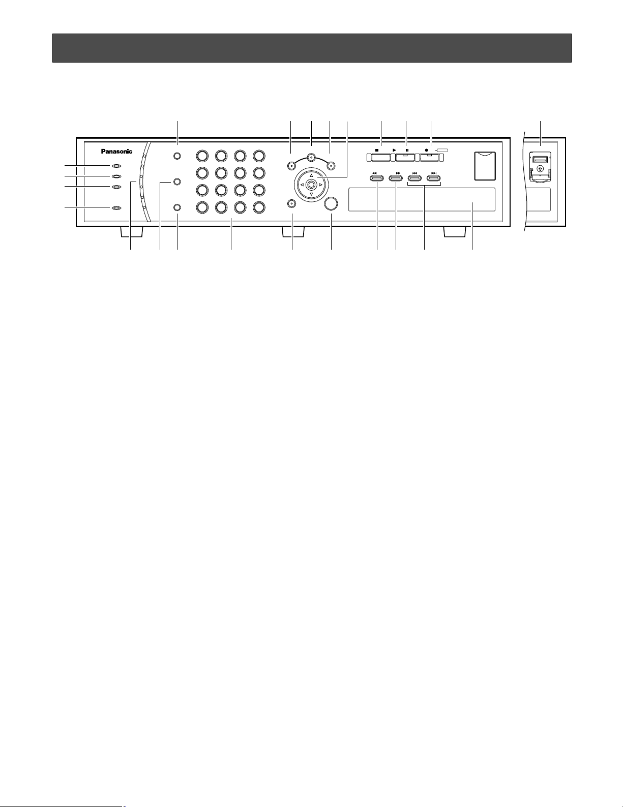
q Error indicator (ERROR)
Blinks orange when an error that may interfere with the
unit’s operation occurs. (e.g. thermal error, cooling fan
malfunction, etc.)
w Alarm Indicator (ALARM)
Blinks red when an alarm occurs. The indicator will stop
blinking and light red steadily when the alarm is reset.
The blinking or lighting indicator will go off when the
[ALARM RESET] button is pressed.
e Timer Indicator (TIMER)
Lights orange when the timer recording is set.
Blinks while the timer recording is being performed.
r Operate Indicator (OPERATE)
Lights green when the power is turned on.
t HDD Access Indicators (HDD1/HDD2/HDD3/HDD4/
HDD5/HDD6)
Blinks green when the hard disk is accessed respectively.
When an error is detected, the indicator will light red.
* The HDD6 indicator is not provided for the
WJ-RT416V.
y Sequence button (SEQUENCE)
Images from the connected cameras will be displayed
sequentially (sequential display) when this button is
pressed. To stop the sequential display, press this button again.
u Multi-screen button (MULTI SCREEN)
Images from the connected cameras will be displayed
on a multi-screen (4/6/9/16) when this button is
pressed. Each time this button is pressed, the multiscreen will change as follows.
16 (CAM1 - CAM16) → 4A (CAM1 - CAM4) →
4B (CAM5 - CAM8) → 4C (CAM9 - CAM12) →
4D (CAM13 - CAM16) → 6A (CAM1 - CAM6) →
6B (CAM7 - CAM12) → 9 (CAM1 - CAM9) →
16 (CAM1 - CAM16)
i Alarm reset button (ALARM RESET)
The unit will be released from the alarm status when this
button is pressed.
o Camera selection buttons
Images from the camera selected using these buttons
will be displayed.
The button will light orange to indicate the camera
channel of which images are currently being recorded.
The camera selection buttons (1 - 10/0) can be used to
enter numbers when operating the setup menu.
!0 Setup button (SETUP)
Press this button to display the setup menu.
!1 Search button (SEARCH)
Press this button to display the time & date search window or the list search window. Refer to pages 24 and
25 for further information about the time & date search
window and the list search window.
!2 Copy button (COPY)
Press this button to display the copy window.
Refer to page 29 for further information about the copy
window.
!3 Arrows button (CDAB)
Use this button for the following.
• To move the cursor to select an area (camera channel) when displaying images on a multi-screen.
• To move the cursor when operating the setup
menu.
When a user is currently logged in the recorder, the
indicator on the button will light blue.
■ Front View
Page 12

12
!4 Escape button (ESC)
Press this button to mute audio when displaying
live/recorded images. When operating the setup menu,
press this button to cancel the settings currently being
edited and go back to the previous page.
!5 Set button (SET)
Press this button to determine the settings when operating the setup menu.
!6 Stop button (STOP)
Press this button to stop playback.
!7 Play/Pause button (PLAY/PAUSE)
Press this button to start playback of the latest recorded
image from the currently selected camera channel.
When this button is pressed during playback, playback
will be paused. Press this button again to release pausing and resume playback. This button lights green during playback and blinks green during pausing.
!8 Record/Record stop button (REC)
Press this button to manually start recording images
from all camera channels (manual recording). When
this button is held down for 2 seconds or more, the
manual recording will stop.
This button lights orange during recording.
!9 Fast reverse playback button (REV)
Press this button to start fast reverse playback.
Playback speed can be changed in 6 steps. (☞ page
22) When this button is pressed during pausing, the
previous frame is displayed.
@0 Fast forward playback button (FWD)
Press this button to start fast forward playback.
Playback speed can be changed in 7 steps. (☞ page
22) When this button is pressed during pausing, the
frame by frame playback will start.
@1 Skip buttons (SKIP)
Press these buttons to skip to the previous/next recorded images. When operating the setup menu, pressing
this button moves the cursor between the setup items
or change the settings.
@2 Copy 2 port (COPY2)
When an external recording device is connected to this
port, images recorded on the built-in HDD can be
copied onto it.
@3 Internal CD/DVD drive (Only for the WJ-RT416V)
Images recorded on the internal hard disk drive can be
copied onto a CD or a DVD. (It is impossible to play
CD/DVD with this internal CD/DVD drive.)
Open the cover and press the button on the front side
of the drive to open the disk tray.
Page 13

13
q Audio out connector (AUDIO OUT)
Audio will be output from this connector. Audio being
input to the AUDIO IN/ALARM OUT terminal or to the
AUDIO IN connectors will be output. When playing
recorded images, audio recorded with the images will
be output.
w Aux in connector (AUX IN)
Use for audio communication between the recorder and
the PC (remote talk). Audio from the microphone connected to this connector will be input.
e Monitor 1 connector (BNC) (MONITOR1)
Images from the cameras connected to the VIDEO IN
connectors will be output.
r Serial terminal (D-SUB, 9-pin) (SERIAL)
This terminal is unavailable.
t Monitor 2 terminal (D-SUB, 15-pin) (MONITOR2)
Connect a video monitor to this connector.
y RS485 port (RS485 (CAMERA))
Connect an RS485 combination camera to this port.
u Data port (DATA)
Connect a PS·Data compatible device to this port.
i Mode switch (MODE)
Use to determine the operational mode of this recorder.
(☞ page 47)
o Network port (10/100BASE-T)
Connect a LAN cable between this port and the network port of a PC. When the recorder is connected with
a network correctly, the link indicator beside the port
will light orange. When data flows through the network
port, the access indicator beside the port will blink
green.
!0 Copy 1 port (COPY1)
When an external recording device is connected to this
port, images recorded on the built-in HDD can be
copied onto it.
!1 Audio in/Alarm out terminal (D-SUB, 25-pin) (AUDIO
IN/ALARM OUT)
Connect an alarming device such as a buzzer or an
alarm lamp to this terminal. When a device such as a
microphone amplifier is connected, audio from it will be
input. Audio being input to this terminal will be output
from the AUDIO OUT connector of the unit and the connected PC.
!2 Alarm in/Control terminal (D-SUB, 25-pin) (ALARM
IN/CONTROL)
Connect an alarming device such as a sensor or a door
switch to this terminal.
!3 Audio in connectors (RCA) (AUDIO IN, 1 - 6)
This connector is the line-in connector. Connect a
device such as a microphone amplifier to input audio
from it. Audio being input to this terminal will be output
from the AUDIO OUT connector of the unit and the connected PC.
!4 Signal ground terminal (SIGNAL GND)
Connect a grounding wire between this terminal and
the signal ground terminal of the other device in the
system.
Otherwise, it may cause oscillation or noise.
!5 Power button (POWER ON/OFF)
When this button is pressed and the power is turned on,
the unit starts operation.
When this button is pressed again and the power is
turned off, operation stops.
!6 Cooling fan
When the temperature inside the unit becomes high,
this fan starts automatically.
AUX IN
AUDIO OUT
IN
OUT
16 15 14 13 12 11 10 9 8 7 6 5 4 3
531
642
12
14 13 12 11 10 9 8 7 6 5 4 3 2 116 15
MONITOR1 MONITOR2
RS485(CAMERA)
MODE
12
DATA
10/100BASE-T COPY1
ALARM IN/CONTOROL
AUDIO IN
SIGNAL GND
POWER
ON
OFF
AC IN
AUDIO IN/ALARM OUT
VIDEO
SERIAL
w
erty uio
!8
q
!7
!0 !1 !2 !3 !4 !5 !6
■ Rear View
Page 14

14
!7 Power cord inlet (AC IN)
Connect the provided power cord to this inlet.
!8 Video in connectors (BNC) (VIDEO IN 1 - 16)/
Video out connectors (BNC) (VIDEO OUT 1 - 16)
Images (video signals) from the cameras connected to
the VIDEO IN connectors will be looped through to the
VIDEO OUT connectors.
Connect system cameras or combination cameras to
the VIDEO IN connectors. The VIDEO IN 1 - 4 connectors are compatible with coaxial cable. When connecting a combination camera, connect it either to the
VIDEO IN 1 - 4 connectors.
Page 15
15
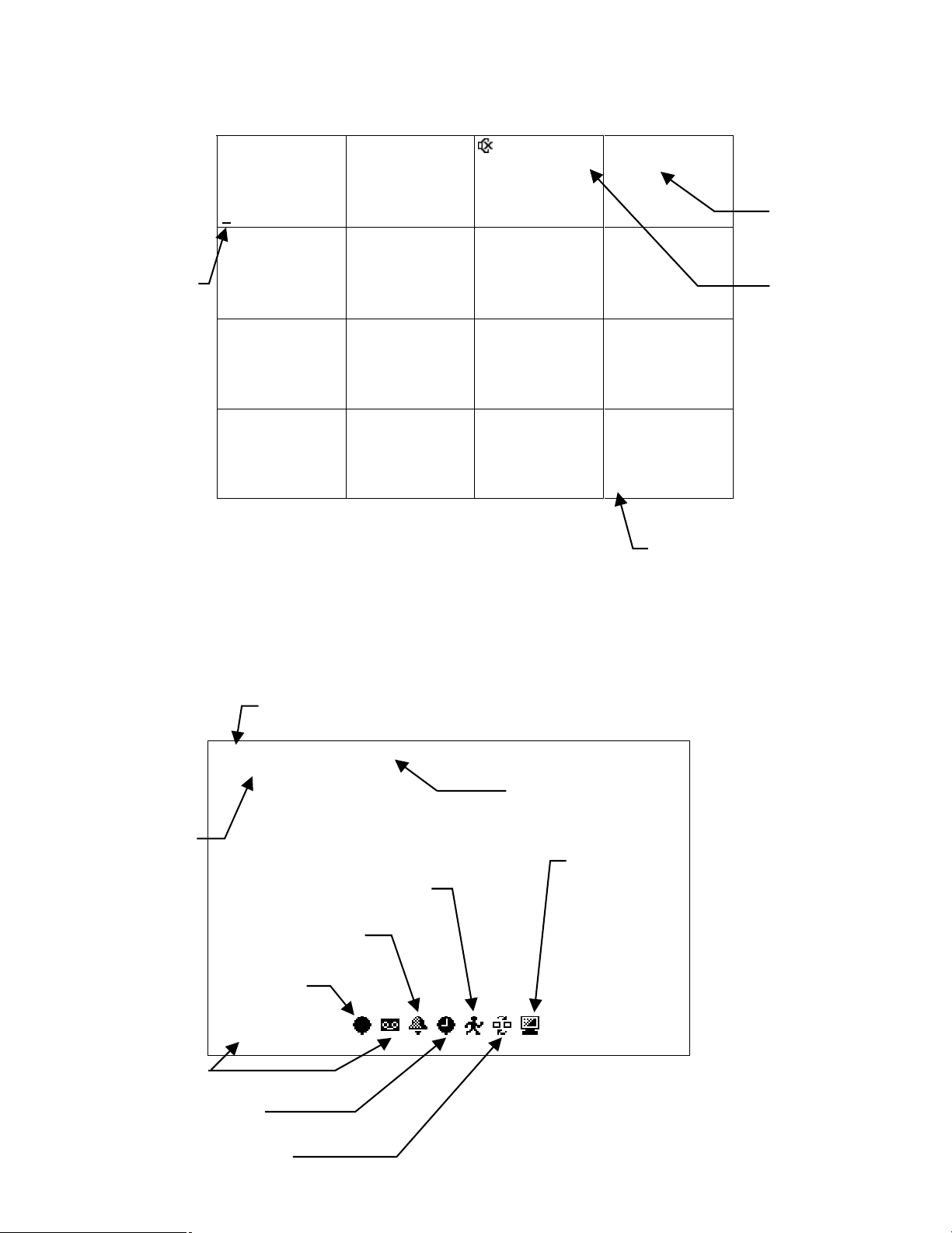
Image display
When displaying images on a 16-split screen
Example: When displaying images from camera channel 1
Currently selected
camera channel
1
5
9 10 11 12
2 3 4
6 7 8
14 15 1613
Sep-04-2006
04:00:00PM
Time and date
Mute icon
Camera title
When displaying on a 16-screen,
numbers 1-16 will be displayed as
shown in the illustration regardless
of the camera title setting.
Information of the recorded images currently being played
Cam1 MANUAL NQ PLAY
Sep-03-2006 03:00:00PM
Playback status
Time and date
of recording
VMD recording
Terminal recording
Recording
icon (indicates
that recording
is in progress)
PLAYBACK
Playback
Live icon
(indicates that
live image
transmission to a
PC is in progress)
Timer recording
Sequential display
Page 16

16
Startup
Start up the recorder as follows.
z
Connect the power cord to a 120 V AC 60 Hz outlet when the model in use is the NTSC model.
When the model in use is the PAL model, connect the power cord to a 220 - 240 V AC 50 Hz outlet.
x
Press the power button to turn on the power of the recorder.
• The OPERATE indicator will light and the system check will start. In the process of the system check, the startup window will be displayed on a monitor.
• When the system check is completed, live images from the connected cameras will be displayed.
Page 17
17
Adjustment of the clock of the recorder
Adjust the clock of the recorder as follows. Check the clock periodically and correct it in the following way if it displays wrong
time. It is also necessary to correct the clock after replacing the built-in backup battery.
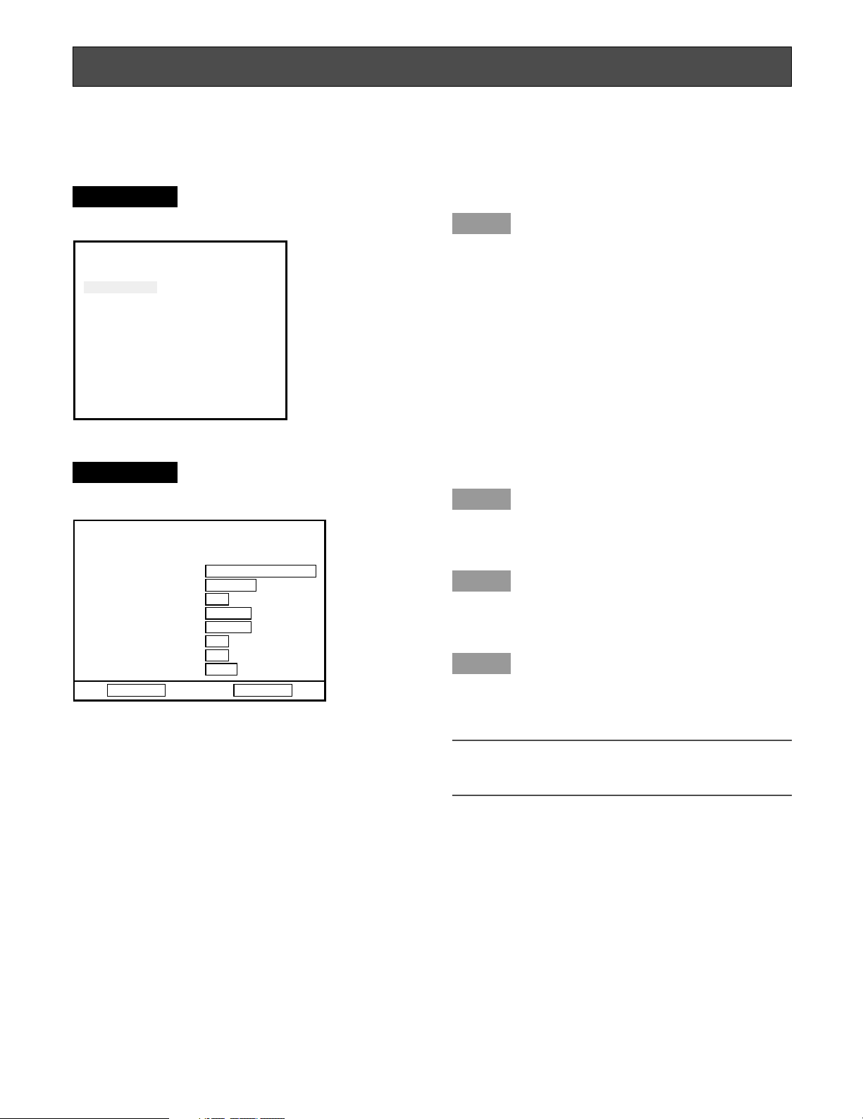
Screenshot 1
Display the setup menu by pressing the SETUP button.
Step 1
Move the cursor onto "System Setup", and then press the
[SET] button.
Screenshot 2
The "System Setup" window will be displayed.
Step 2
Set the time and date using the camera selection buttons
(1 - 10/0).
Step 3
Move the cursor to "Time Zone", and then select a time
zone using the skip buttons (sd).
Step 4
When completing the adjustment, move the cursor onto
"SET" and press the [OK] button.
→ The adjusted time and date will be applied.
Important:
When the clock is adjusted during recording, some of
the recorded images cannot be searched.
Setup Menu
System Setup
Recording Setup
Event Setup
Display Setup
Camera Control Setup
Communication Setup
User Management
Maintenance
System Setup
Month-Day-Year
Time & Date 10-22-2006 11:30:30
(Time Zone) GMT-5:00
Set
Language English
Auto Login User Manager
Auto Logout Time 600 Sec
Error Buzz 002 Sec
Advanced Setup Set→
OK Cancel
Page 18

18
Shutdown of the recorder
To shut down the recorder, do the following.
z
When the manual recording is currently being performed, stop recording.
• Hold down the [REC] button for 2 seconds or more. The lit camera selection button indicating the current recording
camera channel will go off and all recordings will stop.
Refer to page 21 for how to stop the timer recording or the alarm recording.
When playing recorded images, stop playback.
• Press the [STOP] button.
x
Press the power button on the rear panel after confirming that all the HDD access indicators are off.
• When the power supply is cut, the OPERATE indicator will go off.
Important:
• Unplug when unused for long period of time.
• When the recorder has not been used for a certain period, turn on the power of the recorder (approximately once a week)
to prevent interferences with functions.
Page 19

19
Monitor live images from the cameras
It is possible to display live images on a single screen or a multi-screen on the monitor.
It is also possible to display live images sequentially (sequential display).
Display images on a single screen
z
Select a camera channel by pressing the camera selection buttons (1 - 16).
• Live images from the selected camera channel will be displayed on a single screen.
Available functions when displaying live images
Mute
When the [ESC] button is pressed, audio will be muted. When audio is muted, the icon (mute icon) will be displayed.
To cancel the audio mute, press the [ESC] button again.
Important:
The audio mute will be applied to all camera channels. Audio will be recorded with images even when muted during
recording. It is impossible to mute only a specified camera channel.
Display images from cameras on a multi-screen
Images can be displayed on the following multi-screens.
• 4-split screen
• 6-split screen
• 9-split screen
• 16-split screen
Each time the [MULTI SCREEN] button is pressed, the multi-screen will change as follows.
16 (CAM1- CAM16) → 4A (CAM1 - CAM4) → 4B (CAM5 - CAM8) → 4C (CAM9 - CAM12) → 4D (CAM13 - CAM16) →
6A (CAM1 - CAM6) → 6B (CAM7 - CAM12) → 9 (CAM1 - CAM9) → 16 (CAM1 - CAM16)
For 4A - 4D, 6A, 6B and 9, the camera channels can be assigned to specific areas of the multi-screen respectively on the
setup menu. Refer to page 61 for further information.
Page 20

20
Display images from the cameras sequentially (sequential display)
It is possible to sequentially display images from cameras automatically. Images from the cameras will be displayed sequentially according to the settings configured in advance.
The sequential display can be carried out on a single screen or a 4-split screen.
Sequential display on a single screen
z
Make sure that images are displayed not on a 4-split screen, and then press the [SEQUENCE] button.
• The sequential display will start and the icon (sequential display icon) will be displayed.
• To stop the sequential display, press the [SEQUENCE] button again.
Sequential display on a 4-split screen
z
Make sure that images are displayed on a 4-split screen, and then press the [SEQUENCE] button.
• The sequential display will start and the icon (sequential display icon) will be displayed.
• To stop the sequential display, press the [SEQUENCE] button again.
Notes:
• The dwell time (interval of switching from a camera channel to the next camera channel) can be configured on the setup
menu ("Display Setup" – "Sequence Dwell") (☞ page 61).
• It Is impossible to carry out the sequential display during playback.
• The sequence step that is unavailable to display (such as when no video signal) will be skipped.
Page 21

21
Manual recording
Start/stop recording manually.
z
Press the [REC] button.
• Recording of images from all the camera channels except channels which supply no video input signal will start. The
[REC] button and the camera channel selection buttons respective to the channels used for the current recording will
light.
• When recording starts, the icon (recording icon) will be displayed in the area on which images from the camera
channels used for the current recording are displayed.
• To configure the image quality and the recording rate for camera channels independently, configure them on the
setup menu ("Recording Setup" – "Manual Rec. Setup") (☞ page 57).
x
To stop recording, hold down the [REC] button for 2 seconds or more.
• The lit camera selection button and the [REC] button will go off and recording will stop. When recording stops, the
icon (recording icon) will also disappear.
Timer recording
It is possible to start and stop recording according to a recording schedule set in advance.
Recording schedule can be set on the setup menu ("Recording Setup" – "Timer Rec. Setup") (☞ page 57).
Important:
The timer recording cannot be stopped by holding down the [REC] button for 2 seconds or more. To stop the timer recording, select "Off" for each day of the week and for "DAILY" on the setup menu ("Recording Setup" – "Timer Rec. Setup")
(☞ page 57).
Alarm recording
It is possible to start recording at an alarm occurrence (according to the settings configured in advance). Refer to page 27 for
further information about the events.
The setting for the alarm recording can be configured on the setup menu ("Event Setup" – "Alarm Rec. Setup") (☞ page 59).
The alarm recording will stop when the [ALARM RESET] button is pressed or when the set alarm recording duration has
passed.
Important:
• The alarm recording cannot be stopped by holding down the [REC] button for 2 seconds or more.
• The order of recording priority is as follows: (1) Alarm recording, (2) Timer recording, (3) Manual recording
Recording
Page 22

22
Playback
Recorded images can be played as follows. Recorded images will be played on a single screen.
z
Select the desired camera channel by pressing the camera channel selection buttons (1 - 16) or by moving the
cursor onto the area respective to the desired camera channel using the arrows button (CDAB) when displaying images on a multi-screen.
x
Click the [PLAY] button.
• Recorded images will be displayed on a single screen. When playback starts, the icon (playback icon) will be displayed and the [PLAY] button will light.
• When selecting a multi-screen display during playback, recorded images will be displayed in the area of camera
channel 1. Live images will be displayed in the other areas.
Important:
• Playback of the latest recorded image using the selected camera channel will start.
It is impossible to play images currently being recorded.
• When the recording duration of recorded images to be played is too short, it may be impossible to play the recorded
images.
• When recorded images are played on this recorder, the recorded images currently being played cannot be played using a
PC via a network. Likewise, when recorded images are played using a PC via a network, the recorded images currently
being played cannot be played using the recorder.
Note:
When playing recorded images whose image quality and recording rate are low, audio may not be heard properly.
c
To stop playback, press the [STOP] button. When displaying recorded images on a multi-screen, press the
[STOP] button after selecting the area of camera channel 1.
• When the lit [PLAY] button goes off and the playback stops, the icon (playback icon) will also disappear.
Available functions when playing images
Fast forward playback/Fast reverse playback
When the [FWD] button is pressed during playback, fast forward playback will start.
When the [REV] button is pressed during playback, fast reverse playback will starts.
Each time the [FWD] button is pressed, playback speed will change as follows.
SLOW/1FF/2FF/3FF/4FF/5FF/6FF
Each time the [REV] button is pressed, playback speed will change as follows.
1REW/2REW/3REW/4REW/5REW/6REW
When the [PLAY] button is pressed during fast forward playback/fast reverse playback, playback speed will return to the normal playback speed.
Playback speed can be set on the setup menu ("Recording Setup" – "Common Setup" – "Advanced Setup" – "I Frame Interval")
(☞ page 56). The current playback speed will be displayed on the screen.
I Frame
Interval
1234
Playback
speed
SLOW ×1/2 ×1/2 ×1/2 ×1/2
1FF, 1REW ×1 ×2 ×3 ×4
2FF, 2REW ×2 ×4 ×6 ×8
3FF, 3REW ×4 ×8 ×12 ×16
4FF, 4REW ×8 ×16 ×24 ×32
5FF, 5REW ×16 ×32 ×48 ×64
6FF, 6REW ×32 ×64 ×96 ×128
The "I Frame Interval" setting is applied only for playback
images. The values in the table are approximate playback
speed as indications when the playback speed is normal
(x1).
Page 23

23
Skip playback
When the [SKIP s] button is pressed during playback, playback will be skipped to the recorded image of the previous
recorded images. When the [SKIP d] button is pressed during playback, playback will be skipped to the recorded image of
the next recorded images.
Pausing
Playback will be paused when the [PLAY] button is pressed during playback. Playback will be resumed when the [PLAY] button is pressed again.
Frame by frame forward playback
When the [FWD] button is pressed during pausing, frame by frame forward playback will start.
Frame by frame reverse playback
When the [REV] button is pressed during pausing, frame by frame reverse playback will start.
Interval of the frame by frame reverse playback will be determined by the "I Frame Interval" setting ("Recording Setup" –
"Common Setup" – "Advanced Setup" – "I Frame Interval" (☞ page 56).
The following values are only as indications.
I Frame Interval=4: 4 seconds interval
I Frame Interval=3: 3 seconds interval
I Frame Interval=2: 2 seconds interval
I Frame Interval=1: 1 seconds interval
Page 24

24
Search and play
It is possible to search the desired recorded images and play them. The search and play can be carried out when displaying
images on a single screen.
The following is available as the search filter for the search and play.
• Time and date when images had been recorded
• Recording type (Manual recording/Timer recording/Alarm recording)
• Type of the alarm recording (Terminal alarm recording/VMD alarm recording/Command alarm recording)
Start playback by designating the desired time and date of recorded images to be played
It is possible to start playback by designating the desired camera channel and the start time and date of recording.
Screenshot 1
Display the Time & Date Search window by pressing the
[SEARCH] button.
Step 1
Move the cursor onto each setup item and set the search
filter.
Camera No.
Enter the camera channel number to be played using the
camera selection buttons (1 - 10/0).
Start
Enter the start time and date of recording to be played
using the camera selection buttons (1 - 10/0).
Time and date that is specified minutes ago from the current time will be automatically displayed. The difference
between the displayed time and the current time varies
according to the value selected for "Default Search Time"
(☞ page 54).
Step 2
When finishing entering, move the cursor onto "OK" and
press the [SET] button.
→ Playback of searched recorded images will start.
Refer to page 22 for further information about playback
operations.
Note:
When no recorded image found, playback of the next
recorded image will automatically start from the beginning.
Time & Date Search
05
Camera No.
10-22-2006 11:30:30
Start
OK
Cancel
Month-Day-Year
[SEARCH]:List Search
Page 25

25
Search and play with multiple search filters
The following search filters are available for search and play.
• Camera CH: Only recorded images of the selected camera channels will be searched.
• Start/End: Images recorded in the period designated by entering the start time and end time will be searched.
• Filtering: Images recorded by the designated recording type (Manual recording/Timer recording/Alarm recording) and
the alarm recording type (Terminal alarm recording/VMD alarm recording/command alarm recording) will be
searched.
Screenshot 1
Display the search window by pressing the [SEARCH] button twice.
Step 1
Move the cursor onto each setup item and set the search
filter.
Camera No.
Enter the camera channel number to be searched using the
camera selection buttons (1 - 10/0).
Start/End
Designate the time period to be searched by entering the
start and end time and date using the camera selection
buttons (1 - 10/0).
Filtering
Select the recording type and the alarm recording type to
be searched using the skip buttons (sd).
Off: Searches without filtering
Manual: Searches for only images recorded manually
Timer: Searches for only images recorded by the timer
recording
Alarm: Searches for only images recorded by the alarm
recording (Terminal alarm recording/VMD alarm recording/command alarm recording)
Terminal: Searches for only images recorded by the termi-
nal alarm recording
VMD: Searches for only images recorded by the VMD
alarm recording
Com: Searches for only images recorded by the alarm
recording triggered by a command alarm reception
Step 2
When determining the filter settings, move the cursor onto
"OK" and press the [SET] button.
Note:
When "00" is entered for "Camera No.", all of the camera
channels will be searched.
List Search
01
Camera No.
Off
Filtering
10-21-2006 11:30:30
Start
OK
Cancel
Month-Day-Year
10-22-2006 11:30:30
End
Month-Day-Year
[SEARCH]:Time & Date Search
Page 26

26
Screenshot 2
The search result window will be displayed.
Step 3
Move the cursor to the desired recorded images to play.
Prev: The previous page will be displayed.
Next: The next page will be displayed.
Return: The search window will be displayed again.
Step 4
Press the [SET] button after selecting the desired recorded
images.
→ Playback of the selected recorded images will start.
Refer to page 22 for further information about playback
operations.
Note:
The latest 5 000 recorded images will be displayed in
the list form.
Prev Next Return
Search List
Cam Quality Start
08
07
06
05
04
03
02
01
SF
FQ
SF
NQ
EX
SF
FQ
SF
01-24-2006
01-24-2006
01-24-2006
01-24-2006
01-24-2006
01-24-2006
01-24-2006
01-24-2006
10:43:22
10:43:22
10:43:22
10:43:22
10:43:22
10:43:22
10:43:22
10:43:22
01-24-2006
01-24-2006
01-24-2006
01-24-2006
01-24-2006
01-24-2006
01-24-2006
01-24-2006
10:53:22
10:53:22
10:53:22
10:53:22
10:53:22
10:53:22
10:53:22
10:53:22
End
Page 001/002
Page 27

27
The recorder will take the alarm action according to the settings when the following events occur.
• Terminal alarm: When a signal is supplied from an external device such as a door sensor to the ALARM IN/CONTROL ter-
minal, this is stated as an event of a terminal alarm.
• VMD (Video motion detection) alarm: When motion is detected by the VMD function, this is stated as an event of a VMD
alarm.
• Command alarm reception: When a command alarm is supplied from the DATA port and the RS485 port, this is stated as
an event of a command alarm reception.
Notes:
• VMD (Video motion detection) function
When motion (luminance change) is detected in the set VMD area, it will be regarded as a VMD alarm occurrence. It is
possible to configure to record images from the camera to which a VMD alarm has occurred.
Action at an event occurrence (alarm action)
The recorder will take the following alarm action according to the settings at an alarm occurrence.
• The ALARM indicator on the front of the recorder blinks red
• Sounds the buzzer
Refer to page 58 for how to set the buzzer to sound at an event occurrence.
• Provides notification to the connected system device at an event occurrence (Alarm output)
Outputs an alarm signal from the ALARM IN/CONTROL terminal on the rear of the recorder in order to activate an alarming
device (when installed).
Refer to page 60 for how to configure the alarm output port settings.
• Displays images from the camera to which an event has occurred on a single screen (Alarm spot)
Refer to page 58 for how to configure the alarm spot settings.
Notes:
• The alarm spot action will not be taken when the setup menu or a dialogue box (message window) is displayed or in the
process of copying.
• When an event occurred during playback, playback will automatically stop and the alarm spot action will be taken.
• Moves a camera to the preset position
The camera will move to the preset position registered in advance at an event occurrence.
Refer to page 60 for how to configure the settings.
Refer to the operating instructions of the connected camera for the descriptions of how to register the preset position.
• Transmits alarm information to a PC via a network
Refer to the operating instructions (PDF) of the monitoring software on the provided CD-ROM for further information.
Alarm function
ALARM indicator
SEQUENCE
HDD
ERROR
ALARM
TIMER
OPERATE
1
2
MULTI
SCREEN
3
4
5
ALARM
RESET
6
2
1
5
6
9
10/0
13
14
Page 28

28
• Records alarm logs
Time and date or description of the event will be recorded as an alarm log at an event occurrence. Refer to page 68 for further information about the alarm log.
• Starts recording automatically (Alarm recording)
Recording images from the camera to which an event occurred will start automatically at an event occurrence. Refer to
pages 59 and 60 for how to configure the settings for recording at an event occurrence (terminal/command alarm recording/VMD alarm recording).
Depending on the event type, a different icon will be displayed as follows.
Terminal alarm input/Command alarm reception:
VMD (video motion detection):
• Starts recording of images before an event occurs (pre-alarm recording)
It is possible to start recording images several seconds before an event occurred automatically. Refer to page 58 for how
to configure the pre-event recording settings.
• Notification mail of an event occurrence
Notification mail of an event occurrence can be sent to the registered mail addresses. Refer to the operating instructions of
the monitoring software (PDF) on the provided CD-ROM for how to configure the settings.
• Provide notification of an event occurrence to the PC according to the setting of Panasonic alarm protocol
Notification of an event/error occurrence (time and date, event/error type) can be automatically provided to the PC according to the settings of Panasonic alarm protocol.
Refer to the operating instructions of the monitoring software (PDF) on the provided CD-ROM for how to configure the settings.
Note:
Even when an event occurred, the alarm action (including the alarm recording) will not be taken when "AL-M" or "AD-M" is
not selected for "Alarm Duration" of "Terminal" and "VMD". When "AD-M" is selected, the following alarm action will be taken.
• Move a Camera to the Preset Position
• Alarm recording
• Pre-alarm recording
• Archive the alarm log
Cancel the alarm action
The recorder will take the alarm action according to the settings when an event is detected. To cancel the alarm action, press
the [ALARM RESET] button.
Note:
When the setup menu is displayed or when being logging out, the alarm action will not be canceled even when the
[ALARM RESET] button is pressed.
Page 29

29
Copying (Duplicate)
It is possible to copy recorded images onto an external recording device (HDD, DVD-R, CD-R, USB memory, etc.) connected
to the recorder. It is recommended to make back-up copies on a regular basis for unexpected situations such as malfunction
of the HDD.
Important:
• Do not disconnect the cable connecting between the external recording device and the recorder in the process of copy-
ing. Otherwise, it may damage both the recorder and the external recording device.
• When copying recorded images using the WJ-RT416V with the internal CD/DVD drive, the disk drive to be used for copy-
ing will be determined in the following priority.
1. External recording device connected to the COPY2 port (Front)
2. External recording device connected to the COPY1 port (Rear)
3. Internal CD/DVD drive
(When external recording devices are connected to both the COPY1 port (rear) and the COPY2 port (front), recorded
images will be copied only onto the external recording device connected to the COPY2 port.)
• When using an external HDD or a USB memory, format it in FAT32 system in advance.
Screenshot 1
Display the Copy window by pressing the COPY button.
Step 1
Search for recorded images to be copied by setting each
search filter on the "Copy" window.
Camera No.
Enter the camera channel number to be searched using the
camera selection buttons (1 - 10/0).
Start/End
Designate the time period to be searched by entering the
start and end time and date.
Filtering
Select the recording type and the alarm recording type to
be searched using the skip buttons (sd).
Off: Searches without filtering
Manual: Searches for only images recorded manually
Timer: Searches for only images recorded by the timer
recording
Alarm: Searches for only images recorded by the alarm
recording (Terminal alarm recording/VMD alarm recording/command alarm recording)
Terminal: Searches for only images recorded by the termi-
nal alarm recording
VMD: Searches for only images recorded by the VMD
alarm recording
Com: Searches for only images recorded by the alarm
recording triggered by a command alarm reception
Step 2
When determining the filter settings, move the cursor onto
"OK" and press the [SET] button.
Note:
When "00" is entered for "Camera No.", all of the camera
channels will be searched.
Copy
05
Camera No.
Off
Filtering
10-21-2006 11:30:30
Start
OK
Cancel
Month-Day-Year
10-22-2006 11:30:30
End
Month-Day-Year
Page 30

30
Screenshot 2
The "Copy List" window will be displayed.
Notes:
• The latest 5 000 recorded images will be displayed in
the list form.
• When copying is started, all recorded images displayed
in the "Copy List" window will be copied. It is impossible
to copy a specified recorded image.
• Configure the filtering settings and set the start/end
time and date in order to make the size of data to be
copied smaller than the available capacity of the external recording device (copying destination).
Important:
Copying time varies depending on the operating conditions of the recorder. Copying speed becomes lower if
the recorder is used for recording, playing, monitoring
live images on the PC, or other operations at the same
time.
Step 3
Move the cursor to the desired recorded images to be
copied.
Prev: The previous page will be displayed.
Next: The next page will be displayed.
Return: The copy window will be displayed again.
Step 4
Press the [SET] button after moving the cursor onto "Copy
A" or "Copy B".
When "Copy A" is selected, only recorded images will be
copied.
When "Copy B" is selected, the viewer (image player) will
be copied together with recorded images.
→ Copying will start.
When copying is completed, the copy completion message window will be displayed.
When the [SET] button is pressed in the process of
copying, the dialog box asking you whether you wish to
cancel the copying or not will be displayed.
When clicking the [OK] button on the dialog box, copying will be canceled.
When the [OK] button is clicked to cancel copying
recorded images onto a CD-R/DVD-R, the disk being
used to copy recorded images cannot be used again.
Refer to the operating instructions of the monitoring software for how to operate the viewer.
Copy List
Cam Quality Start
08
SF
FQ
SF
NQ
EX
SF
FQ
SF
01-24-2006
01-24-2006
01-24-2006
01-24-2006
01-24-2006
01-24-2006
01-24-2006
01-24-2006
07
06
05
04
03
02
01
Total:20
Copy A:Data Only Copy B:Copy with Viewer
Prev Next Copy A Copy B Return
10:43:22
10:43:22
10:43:22
10:43:22
10:43:22
10:43:22
10:43:22
10:43:22
Size:12.08GB Page 001/023
01-24-2006
01-24-2006
01-24-2006
01-24-2006
01-24-2006
01-24-2006
01-24-2006
01-24-2006
End
10:53:22
10:53:22
10:53:22
10:53:22
10:53:22
10:53:22
10:53:22
10:53:22
Page 31

31
Screenshot 2
The "User Management" window will be displayed.
Step 2
Move the cursor onto "Logout", and then press the [SET]
button.
→ The confirmation window will be displayed. Move the
cursor onto "OK", and then press the [SET] button.
Log in as a different user
To log in as a different user, log out first and log in again.
When logged out, the buttons on the front panel will be locked and the password entry window will be displayed when any of
the buttons is pressed. Enter the user password.
Important:
According to your needs, select "Disable" for "Auto Login User" on the setup menu ("System Setup" – "Auto Login User")
(☞ page 53). When "Disable" is not selected, a user who logged out will automatically logged in as the registered auto
login user when no operation had been made for around 1 minute after logout.
Log out
Screenshot 1
Display the setup menu by pressing the SETUP button.
Step 1
Move the cursor onto "User Management", and then press
the [SET] button.
Setup Menu
System Setup
Recording Setup
Event Setup
Display Setup
Camera Control Setup
Communication Setup
User Management
Maintenance
User Management
User Level Setup
Password
Logout
Page 32

32
Log in
Screenshot 1
When logged out once and press any of the buttons on the
front panel, the password entry window will be displayed.
Step 1
Enter the user password and press the [SET] button.
→ When logged in, the indicator on the arrows button will
light. When failed to log in, the error message window
will be displayed.
Note:
The default password is different according to the user
level as follows.
Manager1: 12345678
Operator1: 123456
Viewer1: 1234
Operation restriction differences between the user levels
*1 The settings can be edited on the setup menu ("User Management" – "User Level Setup"). (☞ page 66)
When being logged out, the user level of "Viewer" will be applied.
*2 Depending on the user level, the available operations of the setup menu varies as follows.
Operator: Logout, alarm log reference, error log reference, system information reference, current recording setting dis-
play
Viewer: Logout only
Input Password
Logout
*1
–
999
–
999
–
999
––
99
––
99
–*1*1
9
–*2*2
9
*1 *1
9
Live image display
Camera channel selection/
Multi-screen selection
Camera channel selection using the
cursor
Sequential display control
Mute control
Manual recording control
Alarm reset
Playback recorded images/Playback
control (Search/Copying)
Setup menu
Viewer Operator Manager
Page 33

33
Disk management
It is possible to format the built-in HDDs and restore HDD management information (list information of recorded images).
Check HDD information
HDD information (total disk size, used disk size, hour meter) and time and date of the latest/oldest data on the HDD can be
checked as follows.
Screenshot 1
Display the setup menu by pressing the SETUP button.
Step 1
Move the cursor onto "Maintenance", and then press the
[SET] button.
Setup Menu
System Setup
Recording Setup
Event Setup
Display Setup
Camera Control Setup
Communication Setup
User Management
Maintenance
Screenshot 2
The "Maintenance" window will be displayed.
Step 2
Move the cursor onto "Disk Management", and then press
the [SET] button.
Maintenance
Alarm Log
Error Log
System Information
Current Recording Setting
Disk Management
Online User Information
Factory Default
Reboot System
Advanced Information
Screenshot 3
The "Disk Management" window will be displayed.
Step 3
The status of the active built-in HDD will be displayed.
No.
The position where the HDD is installed will be displayed.
All Format Information Return
[REC]:Start Format [STOP]:Change HDD
Disk Management
No.
1
2
3
4
232.884GB
232.884GB
232.884GB
5 No Disk Detected
6 No Disk Detected
232.884GB 232.250GB
232.250GB
138.034GB
000.008GB
400h
400h
153h
389h
Capacity Used Hour Meter
1
3
5
2
4
Anterior view
6
Page 34

34
Capacity
The total size of the HDD will be displayed.
Used
The used size of the HDD will be displayed.
Hour Meter
The hour meter of the HDD will be displayed.
Note:
When a HDD is in the faulty state, the indication will displayed on the "Disk Management" window as follows.
No Disk Detected: Indicates that no HDD is connect-
ed.
Disk Unformatted: Indicates that the HDD is not for-
matted with this recorder.
Disk Access Error: Indicates that a HDD access error
occurred.
Data Error: Indicates that the directory structure of the
HDD is broken.
Disk Unacknowledged: Indicates that the recorder
failed to mount the HDD for a reason such as data
number limitation, even though the HDD is in the
normal state.
Disk Type Unfitting: Indicates that the model number
and the disk size of the newly mounted HDD is different from the replaced HDD.
Step 4
Move the cursor onto "Information", and then press the
[SET] button.
Step 5
Check time and date of the oldest data and the latest data,
and then press the [SET] button.
Screenshot 4
The "Disk Information" window will be displayed.
Close
Disk Information
HDD1:01-01-2006 10:00:00 01-31-2006 09:45:00
HDD2:01-31-2006 10:00:00 02-28-2006 09:45:00
HDD3:02-28-2006 10:00:00 03-31-2006 09:45:00
HDD4:03-31-2006 10:00:00 04-30-2006 09:45:00
HDD5:
HDD6:
No Data
No Data
Oldest Latest
Notes:
• The used disk space will not be displayed as "0 GB"
even when no data is saved on the disk since the system uses some of the disk space.
• HDD6 is not provided for the WJ-RT416V.
Page 35

35
Format the HDD
There are two ways of how to format the HDD as follows.
• Format only the selected HDD
• Format all the HDDs simultaneously
Format only the selected HDD
Screenshot 1
Display the "Disk Management" window (☞ page 33).
Step 1
Move the cursor onto the HDD to be formatted, and then
press the [REC] button.
→ The confirmation window will be displayed. Move the
cursor onto "OK", and then press the [SET] button.
Important:
• When the correctly mounted HDD is currently being
used for recording, it is impossible to format it.
• When the selected HDD is in the "Disk Type Unfitting"
state, it is impossible to format it.
Format all the HDDs
Screenshot 1
Display the "Disk Management" window (☞ page 33).
Step 1
Move the cursor onto "All Format", and then press the [SET]
button.
→ The confirmation window will be displayed. Move the
cursor onto "OK", and then press the [SET] button.
All Format Information Return
[REC]:Start Format [STOP]:Change HDD
Disk Management
No.
1
2
3
4
232.884GB
232.884GB
232.884GB
5 No Disk Detected
6 No Disk Detected
232.884GB 232.250GB
232.250GB
138.034GB
000.008GB
400h
400h
153h
389h
Capacity Used Hour Meter
All Format Information Return
[REC]:Start Format [STOP]:Change HDD
Disk Management
No.
1
2
3
4
232.884GB
232.884GB
232.884GB
5 No Disk Detected
6 No Disk Detected
232.884GB 232.250GB
232.250GB
138.034GB
000.008GB
400h
400h
153h
389h
Capacity Used Hour Meter
Page 36

36
Stop power supply to the HDD
When replacing the HDD, it is necessary to stop power supply to the HDD in advance.
Contact your dealer when it is necessary to replace the HDD.
Screenshot 1
Display the "Disk Management" window (☞ page 33).
Step 1
Move the cursor onto any of No.1 - 6, and then press the
[STOP] button.
→ The confirmation window will be displayed. Move the
cursor onto "OK", and then press the [SET] button.
Power supply to the HDD corresponding to the indication "Disk Access Error", "Data Error", "Disk Type
Unfitting" or "Disk Unacknowledged" will be cut.
All Format Information Return
[REC]:Start Format [STOP]:Change HDD
Disk Management
No.
1
2
3
4
232.884GB
Disk Access Error
232.884GB
5 No Disk Detected
6 No Disk Detected
232.884GB 232.250GB
232.250GB
000.008GB
400h
400h
389h
Capacity Used Hour Meter
Screenshot 2
The following message window will be displayed after
around 30 seconds.
Step 2
Replace the HDD. Contact your dealer when it is necessary
to replace the HDD.
Step 3
When completing the HDD replacement, press the [SET]
button.
OK
Replace HDD
The power supply of the HDD have been
turned off. Replace the HDD and
press [SET] button to turn on again.
HDD1
HDD2
HDD3
HDD4
HDD5
HDD6
Screenshot 3
The "Disk Management" window will be displayed again.
Step 4
Since the replace HDD is unformatted yet, format the HDD
(☞ page 35).
All Format Information Return
[REC]:Start Format [STOP]:Change HDD
Disk Management
No.
1
2
3
4
232.884GB
Disk Unformatted
232.884GB
5 No Disk Detected
6 No Disk Detected
232.884GB 232.250GB
232.250GB
000.008GB
400h
400h
389h
Capacity Used Hour Meter
Page 37

37
Restore HDD management information
When information of recorded images on the HDD and HDD management information (list information) do not match, restore
the HDD management information.
Restore of HDD management information sometimes resolves problems such as a playback failure.
Screenshot 1
Display the "Disk Management" window (☞ page 33).
Step 1
Move the cursor onto the HDD whose management information is to be restored, and then press the [PLAY] button.
→ The HDD management information check will start.
When there is nothing wrong with the HDD management information, the confirmation window will be displayed.
Press the [SET] button the "Disk Management" window
will be displayed again.
When there is something wrong with the HDD management information, the message window asking whether
or not to restore the HDD management information will
be displayed.
To restore the HDD management information, press the
[SET] button after moving the cursor onto "OK".
All Format Information Return
[REC]:Start Format [STOP]:Change HDD
Disk Management
No.
1
2
3
4
232.884GB
232.884GB
232.884GB
5 No Disk Detected
6 No Disk Detected
232.884GB 232.250GB
232.250GB
138.034GB
000.008GB
400h
400h
153h
389h
Capacity Used Hour Meter
Page 38

38
Operate the recorder using a PC
It is possible to configure the settings and operate the recorder on a network using the monitoring software when it is installed
on the PC from the provided CD-ROM.
The following are some functions and their features of the monitoring software, and the system requirements for a PC on which
the software can be installed.
Refer to the operating instructions (PDF) of the monitoring software on the provided CD-ROM for further information about each
function and for how to operate the software.
Functions and their descriptions
The operable functions using the monitoring software are as follows.
Monitoring images from the cameras
Images from the cameras can be monitored on the PC.
Playback of recorded images
Recorded images on the recorder can be played and monitored on the PC.
Configuration of the settings of the recorder
The settings of the recorder such as the system setup and
the recording setup can be configured on the PC.
Notification of an event occurrence and its information
Notification of an event/error occurrence (time and date,
event/error type) can be provided to the PC.
Download of recorded images
Recorded images monitored on the PC can be downloaded
(saved) onto the PC.
When an event occurs, it is possible to transmit images
from the camera to which an event occurred.
Audio communication
Audio can be transmitted/received between the recorder
and the PC.
System requirements for a PC
It is recommended to operate the monitoring software on a PC that meets the following system requirements. If using a PC that
does not meet the following system requirements, it may cause problems such as slow imaging or the software becomes inoperable.
OS Microsoft
®
Windows®XP Professional SP2*
Microsoft
®
Windows®XP Home Edition SP2*
*: Tested and confirmed full compatibility with the English edition. Full compatibility with other language
editions cannot be guaranteed.
Computer IBM PC/AT Compatible
CPU Pentium
®
4 3.0 GHz or faster
Memory 512 MB or more
Graphic memory 256 MB or more (independent)
Display driver Overlay compatible
Monitor 1 024 x 768 pixels or more, 24-bit True color or better
Network Interface 10/100 Mbps Network interface card must be installed
Plug-in Microsoft
®
Windows MediaTMPlayer 9 Series or later
Others DirectX 8.0a or later
CD-ROM Drive: It is necessary to read the operating instructions and use the software on the provided
CD-ROM.
Adobe
®
Reader: It is necessary to read the operating instructions on the provided CD-ROM.
Notes:
• When the graphic memory is less than 32 MB, the monitoring software can access only four camera channels concurrently.
(When the graphic memory is less than 64 MB, the monitoring software can access only six camera channels concurrently.)
• When the overlay control is not enabled for the display driver, the monitoring software may not start.
• The monitoring software may not start depending on the version of the display driver. In this case, upgrade the display driver to the latest version.
Page 39

39
Installation
HDD safety mode
When installing the recorder in the rack without turning the power of the recorder off, activate the HDD safety mode.
When the HDD safety mode is activated, the power of the all HDDs will be off. (Recording and playback will be forcibly canceled.)
At the default, the recorder will start up in the HDD safety mode to protect the HDDs from shock, vibration, etc. during installation.
Operating the recorder for the first time
When turning on the power of the recorder, the following message will be displayed.
"ALL HDD MOTORS STOPPED. PRESS [SET] BUTTON TO RESTART."
Press the [SET] button to start up the recorder.
Installation
When installing/uninstalling the recorder (into/from the rack) after starting operation of the recorder in the system, do the following.
z
Restart the recorder using the setup menu ("Maintenance" – "Reboot System"). (☞ page 70)
x
The message "SYSTEM SETTING..." will be displayed (for around 3 seconds) in the process of startup.
Press the [STOP] button while the message "SYSTEM SETTING..." is being displayed.
→ The following message will be displayed.
"ALL HDD MOTORS STOPPED. PRESS [SET] BUTTON TO RESTART."
c
When completing the installation, press the [SET] button.
• The recorder will start up.
Page 40

40
HDD replacement
When the indication "Disk Access Error", "Data Error", "Disk Unacknowledged" or "Disk Type Unfitting" is displayed, it is possible to replace the HDD without stopping the operation of the recorder. (A new HDD must be the same model as of the HDD to
be replaced with.)
It is necessary to stop the power supply to the HDD before starting the HDD replacement. Refer to page 36 for how to stop the
power supply to the HDD, Contact your dealer when it is necessary to replace the HDD.
HDD addition
When the indication "No Disk Detected" is displayed in the "Disk Management" window, an HDD can be added to the recorder.
(It is necessary to turn off the power of the recorder before adding a new HDD.) The recorder is operable with up to six built-in
HDDs. Contact your dealer when it is necessary to add a new HDD.
Page 41

41
Use an EIA-standard 19" rack (depth: 550 mm or more).
Note:
It is necessary to procure four optional rack mount screws (W2-MSS/5008 or M5 x12).
z
Remove the five rubber feet from the bottom of
the recorder using a flathead screwdriver.
x
Place the provided rack mounting brackets on
both sides of the recorder and tighten with the
eight provided screws.
c
Install the recorder with the rack mounting
brackets in the rack by using four rack mounting
screws.
Rack mounting
Important:
• Keep the temperature in the rack below +45 °C {113 °F}.
• Install the recorder in the rack as low as possible, and make a space of 1 unit (44 mm, 1.73") between the recorder and the
other mounted appliances.
• Do not block the front side of the rack such as by attaching a door panel, etc.
• It is recommended to install cooling fans or equivalent equipment to keep the temperature in the rack below +30 °C {86 °F}.
Remove the rubber feet.
Rack mounting screw: M5 x12 (locally procured)
Rack mount bracket fixing screw (provided)
Rack mount bracket (provided)
Page 42

42
Connection
Basic connection
Important:
• When connecting an external recording device, use an optional USB cable to connect it to the COPY1 port on the rear or to
the COPY2 port on the front of the recorder.
• Transmission loss of video signals from the cameras connected to the VIDEO IN 1-8 connectors (VIDEO IN 5-8 connectors
are available only when an optional board is installed) can be compensated by selecting a proper value for the cable compensation setting (Comp.).
S: Suitable when the total cable length between the camera and the recorder is shorter than 500 m
M: Suitable when the total cable length between the camera and the recorder is 500 – 900 m
L: Suitable when the total cable length between the camera and the recorder is 900 – 1 200 m
• Use 5C-2V cable to connect between the recorder and the camera.
• Select a proper value for the cable compensation setting (Comp.) according to the actual length of the cable in use.
Otherwise, images from the camera will not be displayed/recorded correctly.
• Audio signal from a microphone should be supplied to the recorder after amplifying to line level (–10 dBv, 51 kΩ) by an
amplifier.
Combination cameras (VIDEO IN 1 - 4)
System cameras (VIDEO IN 5 - 16)
Microphones
Amplifier
Video monitor
Connect the cables from
the microphone amplifier to
the AUDIO IN connectors.
SEQUENCE
HDD
1
1
ERROR
2
ALARM
3
TIMER
4
5
OPERATE
6
2 3 4
MULTI
5
6 7 8
SCREEN
9
10/0 11 12
ALARM
RESET
13
14 15 16
SEARCH
SETUP COPY
ESC
SET
STOP PLAY PAUSE REC
REC STOP
SKIPFWDREV
+–
Digital Disk Recorder WJ-RT416
Connect the video
monitor to the
monitor 1 connector.
External recording device
connected to the COPY1
(rear) or COPY2 port (front)
Page 43

43
Connection with RS485 cameras
Important:
The maximum length of the cable to be used to connect between a RS485 camera and the recorder is 1 200 m.
Note:
Contact your dealer when connecting cameras using the 2-wire connection.
RS485 cable
(WV-CA48/50)
Unit number: 12
Termination: ON
4-wire connection
AUX IN
AUDIO OUT
MONITOR1 MONITOR2
IN
16 15 14 13 12 11 10 9 8 7 6 5 4 3
OUT
Unit number: 11
Termination: OFF
4-wire connection
RS485(CAMERA)
SERIAL
12
MODE
DATA
10/100BASE-T COPY1
14 13 12 11 10 9 8 7 6 5 4 3 2 116 15
Unit number: 10
Termination: OFF
4-wire connection
VIDEO
Unit number: 9
Termination: OFF
4-wire connection
AUDIO IN/ALARM OUT
ALARM IN/CONTOROL
531
POWER
ON
OFF
642
AUDIO IN
SIGNAL GND
12
AC IN
Combination cameras
(coaxial communication compatible)
Combination cameras (RS485 compatible)
Page 44

44
Connection with PS·Data systems
This is an example of connection when the unit is used together with the PS·Data devices.
If a connected system controller is PS·Data compatible, it is possible to operate this unit or connected devices using the system controller.
Use the RS485 cable provided with the system controller.
Important:
• Terminate both devices on both ends of the connection. Refer to the respective operating instructions for the descriptions
of how to terminate. Termination of this unit can be set with the mode selection DIP switch on the rear panel. (See page
47.)
• When connecting a PS·Data compatible device, it is necessary to set each item of "PS.Data Setup" of "Communication
Setup" according to the system configuration.
• The following are available PS·Data compatible devices.
• System controller: WV-CU650 (Ver 2.10 or later)
• Data multiplex unit: WJ-MP204
• Matrix switcher: WJ-SX650 (Ver. 3.00 or later)
(Any other PS·Data compatible devices are not to be connected.)
When connecting a single unit with a controller
AUX IN
AUDIO OUT
IN
OUT
16 15 14 13 12 11 10 9 8 7 6 5 4 3
531
642
12
14 13 12 11 10 9 8 7 6 5 4 3 2 116 15
MONITOR1 MONITOR2
RS485(CAMERA)
MODE
12
DATA
10/100BASE-T COPY1
ALARM IN/CONTOROL
AUDIO IN
SIGNAL GND
POWER
ON
OFF
AC IN
AUDIO IN/ALARM OUT
VIDEO
SERIAL
This unit
1ON2
Mode selection
DIP switches
A B
1
3
2
4
6
5
7
9
8
0
SYSTEM CONTROLLER
Controller
Termination: ON
Unit Address: 1
RS485 cable
(provided with the controller)
"PS.Data Setup" of "Communication Setup"
on the Setup Menu
• Unit Address (System): 1
• Unit Address (Controller): 2
Page 45

45
When installing this unit between a controller and a system device
AUX IN
AUDIO OUT
IN
OUT
16 15 14 13 12 11 10 9 8 7 6 5 4 3
531
642
12
14 13 12 11 10 9 8 7 6 5 4 3 2 116 15
MONITOR1 MONITOR2
RS485(CAMERA)
MODE
12
DATA
10/100BASE-T COPY1
ALARM IN/CONTOROL
AUDIO IN
SIGNAL GND
POWER
ON
OFF
AC IN
AUDIO IN/ALARM OUT
VIDEO
SERIAL
RS485 cable
POWER
ON
OFF
ALARM
Data Multiplex Unit WJ-MP204
ALARM
SUSPEND
1234
ESCSET
RESET
SUSPEND SET UP
ALARM
UNIT
0
9
8
7
6
5
4
3
2
1
Coaxial communication unit
Termination: ON
Unit Address : 2
1ON2
Mode selection
DIP switches
A B
1
3
2
4
6
5
7
9
8
0
SYSTEM CONTROLLER
Controller
Termination: ON
Unit Address: 1
"PS.Data Setup" of "Communication Setup" on the Setup Menu
• Unit Address (System): 1
• Unit Address (Controller): 2
RS485 cable
Page 46

46
Connection with a PC
Required devices and cables vary depending on how to connect them. Before starting the connections, check the required
devices and cables for your environment. The IP addresses of the recorders in the following connection examples are the
default settings.
Connect the recorder and a PC directly
Important:
When connecting the recorder and a PC directly without using a hub or a router, use a cross LAN cable to connect them.
Add the recorder to the existing network
Install a hub or a router between the recorder and a PC. Use a LAN cable to connect between the recorder and the hub.
LAN cable
(10BASE-T/100BASE-Tx, category 5, cross)
SEQUENCE
HDD
1
1
2 3 4
ERROR
2
ALARM
MULTI
5
SCREEN
3
TIMER
4
9
5
ALARM
RESET
OPERATE
6
13
6 7 8
10/0 11 12
14 15 16
SETUP COPY
ESC
IP address: 192.168.0.250
Subnet mask: 255.255.255.0
SEARCH
SET
STOP PLAY PAUSE REC
REC STOP
SKIPFWDREV
+–
Digital Disk Recorder WJ-RT416
PC
IP address: 192.168.0.x (except 0, 250 and 255)
Subnet mask: 255.255.255.0
HDD
1
ERROR
2
ALARM
3
TIMER
4
5
OPERATE
6
IP address: 192.168.0.250
Subnet mask: 255.255.255.0
Gateway address: 192.168.0.1
SEQUENCE
1
2 3 4
MULT
5
6 7 8
SCREEN
9
10/0 11 12
ALARM
RESET
13
14 15 16
SEARCH
SETUP COPY
ESC
SET
LAN cable
(10BASE-T/100BASE-Tx, category 5, straight)
STOP PLAY PAUSE REC
REC STOP
SKIPFWDREV
+–
Digital Disk Recorder WJ-RT416
Hub/router
IP address: 192.168.0.1
Subnet mask: 255.255.255.0
LAN
PC
IP address: 192.168.0.x (except 0, 1, 250 and 255)
Subnet mask: 255.255.255.0
Gateway address: 192.168.0.1
PC
Page 47

47
Add the recorder to a broadband WAN (Wide Area Network)
Important:
When the recorder is in a WAN, maximum accessible number will become as follows.
* "Accessible number" is the number of the camera channels that can be displayed in the display area of the monitoring
software.
• It is necessary to log in first to play/download recorded images and transmit/receive audio.
• If live images are transmitted using Multicast, the chart above is not applicable.
• Only “Manager1” is capable of voice call. (☞ page 67)
• When displaying images from 5 or more camera channels, or when displaying recorded images in an area on a
multi-screen, only I-frame* will be displayed in all areas on a multi-screen and audio may not be heard.
*: Short for intra frame. I-frame is an image that is to be inserted in the intra refresh period of MPEG images.
DIP Switch Setting
When the unit is used together with the PS·Data devices, use the RS485 cable provided with the system controller.
In this case, it is necessary to terminate both devices on both ends of the connection if they are connected with the RS485
cable.
Termination of this unit can be set with the DIP termination switch on the rear panel, and the setting of the mode selection DIP
switch varies whether to use this unit as a receiver or a system controller.
When connecting to the system controller and this unit is connected as the end of the PS·Data connection, set mode selection
DIP switch 2 to "ON".
When connecting to the system device and this unit is connected as the end of the PS·Data connection, set mode selection
DIP switch 1 to "ON".
Operation
Monitoring of live images
Playback of recorded images
Frame display
Download of recorded images
Audio transmission/reception
Total of 16 areas
Total of 4 areas
4 PCs (4 users)
4 PCs (4 users)
1 PC (1 user)
Accessible number*
Broadband router A (WAN → WJ-RT416)
TCP/UDP port: 2000 (configured on the WJ-RT416)
SEQUENCE
HDD
1
1
ERROR
ALARM
TIMER
OPERATE
2 3 4
2
MULTI
5
6 7 8
SCREEN
3
4
9
10/0 11 12
5
ALARM
RESET
6
13
14 15 16
SEARCH
SETUP COPY
ESC
SET
STOP PLAY PAUSE REC
REC STOP
SKIPFWDREV
+–
Digital Disk Recorder WJ-RT416
Server port: 2000 (editable)
Broadband router B (WAN → PC)
UDP port: 999 (fixed)
PC
WAN
Page 48

Machine connected to the DATA port
48
Mode selection DIP switch:
The dip switch positions are defined by the attribute of the unit connected to the system’s DATA terminal.
Controller
System Device
DIP switch 1
OFF
ON
DIP switch 2
ON
OFF
Page 49

49
Alarm 4 Output (NC)
(Signal GND)
+12 V
Output 4, Normally closed-collector
+12 V output
1 A, 30 V DC max.
800 mA max.
@3
@4
@5
Alarm 3 Output (NO)
Alarm 3 Output (NC)
Alarm 4 Output (COMMON)
Alarm 4 Output (NO)
Output 3, Normally open-collector
Output 3, Normally closed-collector
Common output 4
Output 4, Normally open-collector
1 A, 30 V DC max.
1 A, 30 V DC max.
1 A, 30 V DC max.
1 A, 30 V DC max.
!9
@0
@1
@2
RS485 (CAMERA) port
When connecting an RS485 camera, connect it to the RS485 (CAMERA) port on the rear of the recorder.
AUDIO IN/ALARM OUT terminal
q!
!
Audio input CH7
Audio input CH8
Audio input CH9
Audio input CH10
Audio input CH11
Audio input CH12
Audio input CH13
Audio input CH14
Audio input CH15
Audio input CH16
(Signal GND)
Alarm 1 Output (COMMON)
Alarm 1 Output (NO)
Alarm 1 Output (NC)
Alarm 2 Output (COMMON)
Alarm 2 Output (NO)
Alarm 2 Output (NC)
Alarm 3 Output (COMMON)
Audio input (CH7)
Audio input (CH8)
Audio input (CH9)
Audio input (CH10)
Audio input (CH11)
Audio input (CH12)
Audio input (CH13)
Audio input (CH14)
Audio input (CH15)
Audio input (CH16)
Common output 1
Output 1, Normally open-collector
Output 1, Normally closed-collector
Common output 2
Output 2, Normally open-collector
Output 2, Normally closed-collector
Common output 3
–10 dBv 51 kΩ, unbalanced
–10 dBv 51 kΩ, unbalanced
–10 dBv 51 kΩ, unbalanced
–10 dBv 51 kΩ, unbalanced
–10 dBv 51 kΩ, unbalanced
–10 dBv 51 kΩ, unbalanced
–10 dBv 51 kΩ, unbalanced
–10 dBv 51 kΩ, unbalanced
–10 dBv 51 kΩ, unbalanced
–10 dBv 51 kΩ, unbalanced
1 A, 30 V DC max.
1 A, 30 V DC max.
1 A, 30 V DC max.
1 A, 30 V DC max.
1 A, 30 V DC max.
1 A, 30 V DC max.
1 A, 30 V DC max.
Pin No.
q
w
e
r
t
y
u
i
o
!0
!1
!2
!3
!4
!5
!6
!7
!8
Signal Operation Remark
RS485(CAMERA)
Signal
GND
OUT IN
RBRATBTA
Signal
GND
Block diagram
RA
RB
TA
TB
3
AUDIO IN/ALARM OUT
@5
4
Control circuit
Normally close
output
Common output
Normally open
output
Internal block diagram
In normal
state
At an alarm
occurrence
Page 50

50
ALARM IN/CONTROL terminal
q!
!
Alarm input CH1
Alarm input CH2
Alarm input CH3
Alarm input CH4
Alarm input CH5
Alarm input CH6
Alarm input CH7
Alarm input CH8
Alarm input CH9
Alarm input CH10
Alarm input CH11
Alarm input CH12
Alarm input CH13
Alarm input CH14
Alarm input CH15
Alarm input CH16
Time adjust input
Error output
HDD error output
(Signal GND)
(N.C.)
An event action will be taken according
to the setting.
An event action will be taken according
to the setting.
An event action will be taken according
to the setting.
An event action will be taken according
to the setting.
An event action will be taken according
to the setting.
An event action will be taken according
to the setting.
An event action will be taken according
to the setting.
An event action will be taken according
to the setting.
An event action will be taken according
to the setting.
An event action will be taken according
to the setting.
An event action will be taken according
to the setting.
An event action will be taken according
to the setting.
An event action will be taken according
to the setting.
An event action will be taken according
to the setting.
An event action will be taken according
to the setting.
An event action will be taken according
to the setting.
The clock of the recorder will be set to
00 (min) by signal input. (Time correction range: ±15 minutes)
Signal output upon an error detection
(Thermal error (47 °C {117 °F} or higher), fan error, video loss, password
entry failure (3 times straight incorrect
password entry), no HDD detection)
Signal output upon a HDD error detection
Not available
Non-voltage make contact input, pulse
width: 100 ms or more
Non-voltage make contact input, pulse
width: 100 ms or more
Non-voltage make contact input, pulse
width: 100 ms or more
Non-voltage make contact input, pulse
width: 100 ms or more
Non-voltage make contact input, pulse
width: 100 ms or more
Non-voltage make contact input, pulse
width: 100 ms or more
Non-voltage make contact input, pulse
width: 100 ms or more
Non-voltage make contact input, pulse
width: 100 ms or more
Non-voltage make contact input, pulse
width: 100 ms or more
Non-voltage make contact input, pulse
width: 100 ms or more
Non-voltage make contact input, pulse
width: 100 ms or more
Non-voltage make contact input, pulse
width: 100 ms or more
Non-voltage make contact input, pulse
width: 100 ms or more
Non-voltage make contact input, pulse
width: 100 ms or more
Non-voltage make contact input, pulse
width: 100 ms or more
Non-voltage make contact input, pulse
width: 100 ms or more
Non-voltage make contact input, pulse
width: 100 ms or more
Open collector output, 100 mA or less,
24 V DC max.
Open collector output, 100 mA or less,
24 V DC max.
Pin No.
q
w
e
r
t
y
u
i
o
!0
!1
!2
!3
!4
!5
!6
!7
!8
!9
@0 - @4
@5
Signal Operation Remark
3
ALARM IN/CONTOROL
@5
4
Page 51

51
Setup menu
It is necessary to configure the settings on the setup menu in advance to operate the recorder.
Display the setup menu on the monitor and configure the settings.
Setup menu chart
Setup item Description Page
System Setup Configure the settings relating to the system such as the clock adjust-
ment, language setting, auto login user, etc.
Recording Setup
Common Setup Configure the basic settings to be applied regardless of the recording
type (manual recording, timer recording, alarm recording).
Manual Rec. Setup Configure the image quality and the recording rate for the manual
recording.
Timer Rec. Setup Configure the schedule settings of the timer recording.
Event Setup
Common Setup Configure the basic settings relating to the event action to be applied
regardless of the event type.
Alarm Rec. Setup Configure the settings for the alarm recording.
Display Setup Configure the settings relating to image display.
Camera Control Setup Configure the communication type for the camera control and the
cable compensation setting for each channel.
Communication Setup
Network Setup Configure the basic settings relating to the network connection.
RS485 Setup Configure the RS485 settings.
PS.Data Setup Configure the PS·Data settings.
User Management
User Level Setup Configure the operational level of "operator" and "viewer" for each
channel.
Password Set the password for each user level.
Logout Log out the recorder.
Maintenance
Alarm Log Log of event occurrences can be checked.
Error Log Log of error occurrences can be checked.
System Information System information such as the firmware version, MAC address, etc.
can be checked.
Current Recording Settings The current recording settings for each camera channel such as the
recording rate can be checked.
Disk Management Format of the built-in HDDs and restore of HDD management informa-
tion (list information of recorded images) are available.
Online User Information Information and operational status (user name, etc.) of the users who
is currently accessing the recorder can be checked.
Factory Default Reset the current settings to the default.
Reboot System Reboot of the recorder is available.
Advanced Information Log of operations and accesses can be checked.
Firmware upgrade is also available.
53
55
57
57
58
59
61
62
63
64
64
66
67
67
68
68
69
69
69
70
70
70
71
Page 52

52
Basic operation of the setup menu
Screenshot 1
Display the setup menu by pressing the SETUP button.
Step 1
Press the [SET] button after selecting the desired setup
item using the arrows button (C or D).
Setup Menu
System Setup
Recording Setup
Event Setup
Display Setup
Camera Control Setup
Communication Setup
User Management
Maintenance
Screenshot 2
The submenu of the selected setup item will be displayed.
(Example: When "Recording Setup" is selected)
Step 2
Press the [SET] button after selecting the desired submenu
using the arrows button (C or D).
Recording Setup
Common Setup
Manual Rec. Setup
Timer Rec. Setup
Screenshot 3
The setup window of the selected submenu will be displayed.
(Example: When "Common Setup" is selected)
Step 3
Configure each setting on the setup window.
To select the setup item: Move the cursor onto the
desired setup item using the arrows button (CDAB).
To change the parameter, to move the cursor on the
setup window: Press the [SKIP s] or [SKIP d] button.
To enter a number: Press the camera selection buttons.
To go back to the previous page: Press the [ESC] button.
Step 4
To save the settings, move the cursor onto "OK" and press
the [SET] button.
To cancel the edited settings, move the cursor onto
"Cancel" and press the [SET] button.
Common Setup
Power On Manual Rec.
Off
Overwrite
On
Audio Select
Set
Advanced Setup
Set→
OK
Cancel
Page 53

53
■ Time & Date Setup (Time Zone)
Adjust the clock of the recorder. Select the time zone
according to the location where the recorder is.
Refer to page 17 for how to adjust the clock.
Default: GMT –5:00 (NTSC model)
GMT +0:00 (PAL model)
■ Language
Select the display language from the following.
English/Japanese/Chinese/Custom
When selecting "Custom", display characters can be
changed according to your needs. Refer to the operating
instructions of the monitoring software (PDF) on the provided CD-ROM for further information.
Default: English
■ Auto Login User
Configure the auto login user setting.
Disable: No user can log in automatically.
Viewer/Operator/Manager: Log in the recorder with its own
user level.
Default: Manager
■ Auto Logout Time
When no operation has been made for a period specified in
advance by a currently logged user (who is not an auto
login user), this user will forcibly be logged out.
005 - 999 (Sec)
Default: 600 (Sec)
■ Error Buzz
Set the sounding duration of the buzzer that starts sounding
at an error occurrence.
000 - 180 (sec)
When "000" is selected, the buzzer will not sound.
Default: 002 (sec)
■ System Setup(Advanced)
The following window will be displayed when the [Set ] button is pressed after moving the cursor onto "Set→".
Date Format
Select a time format from the following.
(Example: October 5, 2006)
yyyy-mm-dd: 2006-10-05
mmm-dd-yyyy: Oct-05-2006
mm-dd-yyyy: 10-05-2006
dd-mm-yyyy: 05-10-2006
dd-mmm-yyyy: 05-Oct-2006
Default: mmm-dd-yyyy (NTSC model)
dd-mm-yyyy (PAL model)
Note:
Display of month will be "mm (numeric)" except when
displaying images (☞ page 15) and "Highest
Temperature" of "System Information" (☞ page 69).
(Month will not be displayed in alphabet (mmm).)
Time Format
Select a time format to be displayed when displaying
live/recorded images from the following.
(Example for 3 o’clock in the afternoon)
12h: 3:00:00 PM
24h: 15:00:00
Default: 12h (NTSC model)
24h (PAL model)
System Setup
Month-Day-Year
Time & Date 10-22-2006 11:30:30
(Time Zone) GMT-5:00
Set
Language English
Auto Login User Manager
Auto Logout Time 600 Sec
Error Buzz 002 Sec
Advanced Setup Set→
OK Cancel
Configure the system settings [System Setup]
Configure the settings relating to the system such as the clock adjustment, language setting, auto login user, etc.
System Setup (Advanced)
Date Format mmm-dd-yyyy
Time Format 12h
Auto Adjust Time off
Summer Time (DST) off
Summer Time (DST) Table Set
Auto Data Delete 000 Days
Default Search Time 15 Min Before
OK Cancel
Page 54

54
Auto Adjust Time
When signal is input to the time adjust input terminal on the
rear of the recorder (☞ page 50), the clock of the recorder
will be set to "00" minute. The clock will be set to "00" minute
only when signal is input at the following time.
• Between 00 minutes 00 seconds and 14 minutes 59
seconds, every hour
• Between 45 minutes 00 seconds and 59 minutes 59
seconds, every hour
The clock will be set to "00 minutes 00 seconds" of the closest hour.
Example:
When "15:00" is set for "Time"
Signal is supplied at 14:50:00 (hour:minute:second) →
Set at 15:00:00
Signal is supplied at 15:14:45 → Set at 15:00:00
Signal is supplied at 15:20:00 → Time will not be
adjusted.
On: Adjust the clock automatically.
Off: Do not adjust the clock automatically.
Default: Off
Summer Time (DST)
Select "Auto" or "Off" to determine whether or not to apply
summer time.
Auto: Apply summer time automatically in accordance with
the settings for switching to summer time.
Off: Do not apply summer time.
Default: Off
Summer Time (DST) Table
Set the start/end date and time for summer time. The following window will be displayed when the [SET] button is
pressed after moving the cursor onto "Set".
Default: As shown in the illustration above.
Auto Data Delete
Configure the settings to delete recorded images automatically when the set days have passed from the day the
images were recorded.
000 - 200 (Days)
When "000" is selected, images will not be deleted automatically.
Default: 000 (Days)
Default Search Time
It is possible to automatically set the start time (of time
ranged to be searched) that is specified minutes ago from
the current time when displaying the search window such
as the "Time & Date Search" window.
For example, when "15 (Min Before)" is selected and the
search window is displayed at 10:00, "9:45" will automatically be entered for the start time on the search window.
00 - 60 (Min Before)
Default: 15 (Min Before)
Summer Time (DST) Table
IN
Month-Day-Year Time
03-25-2007 02 :00
1
03-30-2008 02 :00
2
03-29-2009 02 :00
3
03-28-2010 02 :00
4
03-27-2011 02 :00
5
OK
OUT
Month-Day-Year Time
10-28-2007 02 :00
10-26-2008 02 :00
10-25-2009 02 :00
10-31-2010 02 :00
10-30-2011 02 :00
Cancel
Page 55

55
Configure the recording settings [Recording Setup]
Configure the settings for recording (manual recording, timer recording, alarm recording).
q Configure the common recording settings [Common Setup]
Configure the basic settings to be applied regardless of the recording type (manual recording, timer recording, alarm recording).
■ Power On Manual Rec.
Select "On" or "Off" to determine whether or not to automatically start manual recording when the power of the recorder
is turned on.
On: Start recording automatically.
Off: Do not start recording automatically.
Default: Off
■ Overwrite
Select "On" or "Off" to determine whether or not to overwrite
recorded images when the available disk space is running
out.
On: Overwrite recorded images.
Off: Do not overwrite recorded images.
Default: On
■ Audio Select
Select "On" or "Off" for each camera channel to determine
whether or not to record images with audio.
The following window will be displayed when the [SET] button is pressed after moving the cursor onto "Set".
On: Record audio together with images.
Off: Record only images.
Default: Off
Note:
When "Off" is selected, no audio will be heard through
this software.
q
w
e
Common Setup
Power On Manual Rec.
Off
Overwrite
On
Audio Select
Set
Advanced Setup
Set→
OK
Cancel
Recording Setup
Common Setup
Manual Rec. Setup
Timer Rec. Setup
Audio Select
Cam1
Cam3
Cam5
Cam7
Cam9
Cam11
Cam13
Cam15
OK
Off
Off
Off
Off
Off
Off
Off
Off
Cam2
Cam4
Cam6
Cam8
Cam10
Cam12
Cam14
Cam16
Off
Off
Off
Off
Off
Off
Off
Off
Cancel
Page 56

56
■ Advanced Setup
The following window will be displayed when the [SET] button is pressed after moving the cursor onto "Set→".
Time Per File
Determine the recording time length of the recorded
images to be saved as a file. Recorded images will be
divided into files and the recording time length of each file
will be the selected time length.
05 - 60 (Min)
Default: 15 (Min)
I Frame Interval
Determine the I-Frame insertion interval.
1 - 4 (Sec)
Default: 4 (Sec)
Resolution
Determine the resolution of recorded images. The following
window will be displayed when the [SET] button is pressed
after moving the cursor onto "Set".
Select a resolution for each camera channel from the following.
Field: Standard (NTSC model: 704 x 240, PAL model: 704 x
288)
SIF: Low (NTSC model: 352 x 240, PAL model: 352 x 288)
---: No recording and image transmission is carried out.
Default: Field
Common Setup (Advanced)
Time Per File
I Frame Interval
Resolution
OK
15 Min
4
Set
Cancel
Resolution
Cam1
Cam3
Cam5
Cam7
Cam9
Cam11
Cam13
Cam15
Field
Field
Field
Field
Field
Field
Field
Field
OK
Cam2
Cam4
Cam6
Cam8
Cam10
Cam12
Cam14
Cam16
Field
Field
Field
Field
Field
Field
Field
Field
Cancel
Page 57

57
w Configure the manual recording settings [Manual Rec. Setup]
Configure the settings for manual recording that starts recording when the [REC] button is pressed.
■ Camera No.
Select a camera channel to be used for manual recording.
Note:
The camera selection buttons (1 - 10/0) are available for
the camera channel selection.
■ Rec. Quality
Select an image quality for recorded images from the following.
SP Fine: Highest quality
Fine: High quality
Normal: Standard quality
Extended: Low quality
Default: SP Fine
■ Rec. Frame Rate
Select a recording frame rate from the following.
Full, 1/2F, 1/4F, 1/8F, 1/16F
(When "Full" is selected, recording frame rate will be 30
frames/sec for NTSC model and 25 frames/sec for PAL
model.)
Default: Full
Note:
When the [SET] button is pressed after moving the cursor onto "All", the same settings for "Rec. Quality" and
"Rec. Frame Rate" will be applied to all of the camera
channels.
■ Camera No., Rec. Quality, Rec. Frame Rate
These settings can be configured in the same manner as
for "Manual Rec. Setup". Refer to the "Manual Rec. Setup"
section.
■ Recording time range
Set the start time and end time for the desired day of the
week, and then select "On".
Up to 2 time ranges can be set as the timer recording
schedule.
To set the same time range for every day of the week, enter
the start and end time for "DAILY".
When "On" and "Off" of 2 different schedules are set in the
same time range, the timer recording will be carried out
according to the schedule for which "On" is selected.
Note:
When the [SET] button is pressed after moving the cursor onto "All", the same settings for "Rec. Quality", "Rec.
Frame Rate" and "Recording time range" will be applied
to all of the camera channels.
e Configure the timer recording settings [Timer Rec. Setup]
Designate a day of the week and time when the timer recording is to be started (timer recording schedule).
Manual Rec. Setup
Camera No.
01▲
Rec. Quality
SP Fine
Rec. Frame Rate
Full
OK
All
Cancel
Timer Rec. Setup
01
SUN
Camera No.
SP Fine
Full
MON
TUE
WED
THU
FRI
SAT
DAILY
All
OK Cancel
00: 00 24: 00 Off 00: 00 24: 00 Off
00: 00 24: 00 Off 00: 00 24: 00 Off
00: 00 24: 00 Off 00: 00 24: 00 Off
00: 00 24: 00 Off 00: 00 24: 00 Off
00: 00 24: 00 Off 00: 00 24: 00 Off
00: 00 24: 00 Off 00: 00 24: 00 Off
00: 00 24: 00 Off 00: 00 24: 00 Off
00: 00 24: 00 Off 00: 00 24: 00 Off
Page 58

58
Configure the alarm action settings [Event Setup]
Configure the settings relating to the alarm action that is to be taken at an event occurrence.
Refer to page 27 for further information about the event type and the alarm action.
q Configure the common settings for the alarm recording [Common Setup]
Configure the common settings relating to the alarm action that is to be taken when an event (terminal alarm, VMD alarm, command alarm) occurred.
■ Alarm Buzz
Select "On" or "Off" to determine whether or not to sound the
buzzer at an event occurrence. The selected duration for
"Alarm Duration" of "Alarm Rec. Setup" (☞ page 59) will be
applied as the sounding duration of the buzzer.
On: Sound the buzzer
Off: Do not sound the buzzer
Default: On
■ Alarm Spot
Select "On" or "Off" to determine whether or not to display
images from the camera that is selected for "Alarm Spot
Camera No." of "Alarm Rec. Setup (Advance)" (☞ page 59)
on a single screen at an event occurrence.
On: Display images from the selected camera.
Off: Do not display images from the selected camera.
Default: On
Note:
The screen that was displayed immediately before an
event resumes after the event is finished.
■ Pre Alarm Recording
Select "On" or "Off" to determine whether or not to start
recording from the specified seconds before an event
occurrence (pre-alarm recording).
On: Start the pre-alarm recording.
Off: Do not start the pre-alarm recording.
Default: Off
Notes:
• Maximum recording duration of the pre-alarm recording
is approximately 5 seconds. Recording duration of the
pre-alarm recording varies depending on the following
settings.
• I Frame Interval
• Capture Resolution
• Rec. Quality
• Rec. Frame Rate
• Audio is not recorded during pre-alarm recording.
Common Setup
Alarm Buzz
On
Alarm Spot
On
Pre Alarm Recording
Off
OK
Cancel
q
w
Event Setup
Common Setup
Alarm Rec. Setup
Page 59

59
w Configure the alarm recording settings [Alarm Rec. Setup]
Configure the settings relating to the alarm recording that starts upon an event occurrence.
■ Alarm No.
"Alarm No." indicates the following according to the event
type.
Terminal input: Terminal used for the terminal alarm
recording.
VMD: Camera channel
Command alarm reception: Camera channel
Note:
The camera selection buttons (1 - 10/0) are available for
the camera channel selection.
■ Rec. Quality
■ Rec. Frame Rate
These settings can be configured in the same manner as
for "Manual Rec. Setup". Refer to page 57 for further information.
■ Term (Alarm Duration)
Determine the alarm action to be taken and the time range
when the alarm action is to be taken upon a terminal input
or a command alarm reception. The alarm action to be
taken can be determined from the following.
AL-M: All the set alarm actions will be taken upon a termi-
nal input.
AD-M: Some of the alarm action will be taken upon a termi-
nal input.
(Refer to the "Action at an event occurrence (alarm
action)" section on page 27.)
Off: No alarm action will be taken.
Default: Alarm Duration 1: 00:00 - 24:00, Off
Alarm Duration 2: 00:00 - 24:00, AL-M
Note:
When "AL-M" and "AD-M" of 2 different alarm durations
are set in the same time range, the alarm action will be
taken according to the setting for the alarm duration
with "AL-M".
■ Term (Rec. Channel)
Set the camera channel to be used for the alarm recording
upon a terminal input or a command alarm reception.
00 - 16
When "00" is selected, images from all of the camera
channel will be recorded.
Default: (Same value set for "Alarm No.")
■ VMD (Alarm Duration)
Determine the alarm action to be taken and the time range
when the alarm action is to be taken upon a VMD alarm.
The alarm action to be taken can be determined from the
following.
AL-M, AD-M, Off
Default: 00:00 - 24:00, Off (for both Alarm Duration 1 and
2)
■ VMD (Rec. Channel)
The camera channel used for the alarm recording upon a
VMD alarm will be displayed.
The displayed camera channel is the same camera channel
number as "Alarm No." (camera channel number from
which the VMD alarm is detected). Editing is unavailable.
■ VMD (Sensitivity)
Set the sensitivity level of the VMD function.
01 (high) - 99 (low)
Default: 10
Alarm Rec. Setup
Alarm No.
Set→
SP Fine
Full
Rec. Channel
01
Term
00:00 24:00 Off 00:00 24:00 AL-M
Rec. Channel
01
Sensitivity
10
Area Setup
Set
VMD
00:00 24:00 Off 00:00 24:00 Off
01
Advanced Setup
OK
All
Cancel
Page 60

60
■ VMD (Area Setup)
Set the VMD area.
The following window will be displayed when the [SET] button is pressed after moving the cursor onto "Set".
Green area: Set as the VMD area.
Clear area: Not set as the VMD area.
Red area: Cursor
Light blue area: Set as the VMD area, and currently motion
is being detected.
The VMD area can be set using the following buttons.
Arrows button: Select an area.
[SKIP d]/[SKIP s] buttons: Determine whether or not to
set the selected area as the VMD area (green: set as the
VMD area, clear: not set as the VMD area).
When completing the VMD area setting, press the [ESC]
button.
The "Alarm Rec. Setup" window will be displayed.
Move the cursor onto "OK" and press the [SET] button to
apply the settings.
Default: All areas are set as the VMD area.
Notes:
• The colors of the VMD areas may look not exactly as
described depending on the brightness or contrast of
the images displayed in the areas.
• The VMD area cannot be set for "Alarm No." to which no
video signal is supplied.
■ Advanced Setup
The following window will be displayed when the [SET] button is pressed after moving the cursor onto "Set→".
Configure the following settings on the setup window of
each "Alarm No." (☞ page 59).
Rec. Duration
Set the alarm recording duration.
000, 030 - 999 (sec)
When "000" is selected, recording will not stop until the
alarm is reset.
Default: 030 (sec)
Alarm Duration
Set the active duration of the alarm action (LED blinking,
buzzer sounding, alarm output from the terminal on the rear
of the recorder).
001 - 999 (Sec)
Default: 030 (Sec)
Alarm Output Port
Select a port from which an alarm signal is output.
0 - 4
When "0" is selected, no alarm signal will be output.
Default: 0
Alarm Spot Camera No.
Select a camera channel from which images are to be displayed on a single screen at an event occurrence.
1 - 16
Default: (Same value set for "Alarm No.")
Preset Camera No.
Select a camera channel that the connected camera is to
be moved to the preset position at an alarm occurrence.
1 - 16
Default: (Same value set for "Alarm No.")
Preset Position
Set the preset position to which the camera moves at an
event occurrence.
000 - 256
When "000" is selected, the camera will not move at an
event occurrence.
Default: 000
[All] button
When the [SET] button is pressed after moving the cursor
onto "All", the same settings will be applied to the following
for all of the "Alarm No.".
• Rec. Quality
• Rec. Frame Rate
• Time range of each schedule
• Sensitivity
• Rec. Duration (Advanced Setup)
• Alarm Duration (Advanced Setup)
• Alarm Output Port (Advanced Setup)
Clear (colorless)
areas (not set as
Cursor (red)
Green areas
(set as the
VMD areas)
the VMD areas)
No.01 Alarm Rec. Setup(Advanced)
Rec. Duration
Alarm Duration
Alarm Output Port
Alarm Spot Camera No.
Preset Camera No.
Preset Position
OK
060 Sec
030 Sec
0
01
01
000
Cancel
Page 61

61
Configure the display settings [Display Setup]
■ Status Display
Determine which information is to be displayed.
All: All information will be displayed.
Status: The status icons and time and date will be dis-
played.
Name: The camera title and time and date will be dis-
played.
Play: Time and date of the recorded images currently
being played will be displayed.
Off: No information will be displayed.
Default: All
Note:
Error information will be displayed regardless of the setting.
■ Sequence Dwell
Set the dwell time of the sequential display (interval of
switching from a camera channel to the next camera channel).
5 - 30 (sec)
Default: 5 (sec)
■ Camera Allocation Setup
Allocate the camera channels to the areas of multi-screen
(4/6/9). Move the cursor to the desired area of multi-screen
and determine the camera channel to be allocated to the
selected area using the camera selection buttons (1-10/0).
Default: As shown in the illustration above.
Important:
• The area allocated for camera channel 1 is impossible
to change.
• The same camera channel cannot be allocated to two
or more areas of the same multi-screen.
Display Setup
Status Display
All
Sequence Dwell
05 Sec
Camera Allocation Setup
Set
OK
Cancel
Camera Allocation Setup
4-screen A
01 02
03 04
6-screen A
01
04
02
050306
OK
4-screen B
05 06
07 08
6-screen B
10
07
110912
4-screen C
09 10
11 12
08
4-screen D
9-screen
01
04
070308
Cancel
13 14
15 16
02
06
05
09
Page 62

62
Configure the settings relating to the camera control [Camera Control Setup]
Configure the communication type for the camera control and the cable compensation setting for each channel.
■ Type
Select a camera control method from the following.
Coax: Control the camera using the coaxial communica-
tion. (Cam 1 - 8 are available (Cam 5-8 are available
only when an optional board is installed).)
RS485: Control the cameras using the RS485 communica-
tion.
Off: Do not control the cameras.
Default: Coax (Cam 1 - 4), PSD (Cam 5 - 16)
■ Protocol
Select "Panasonic" when "RS485" is selected for "Type".
Default: Panasonic
■ Compensation
Select the cable length when "Coax." is selected for "Type".
(Cam 1 - 8 are available (Cam 5-8 are available only when
an optional board is installed).)
It is necessary to configure to control the camera using the
coaxial communication.
S: Suitable when the total cable length between the camera
and the recorder is shorter than 500 m
M: Suitable when the total cable length between the cam-
era and the recorder is 500 - 900 m
L: Suitable when the total cable length between the camera
and the recorder is 900 - 1 200 m
Default: S
Notes:
• To display the "Camera Control Setup" page for camera
channels 9-16, click the [9-16] button.
• The setting of compensation (cable loss) will be ignored
when receiving any alarm from cameras during communication setup.
Important:
Stop recording before changing the settings relating to
the camera control. Otherwise, the cable compensation
setting (Comp.) may not be saved.
Camera Control Setup
Type Protocol Compensation
OK
9 - 16
Cancel
Cam 1 Coax
Coax
Coax
Coax
PSD
PSD
PSD
PSD
Panasonic
Panasonic
Panasonic
Panasonic
Panasonic
Panasonic
Panasonic
Panasonic
Cam 2
Cam 3
Cam 4
Cam 5
Cam 6
Cam 7
Cam 8
S
S
S
S
S
S
S
S
Camera Control Setup
Type Protocol
OK
1 - 8
Cancel
Cam 9 PSD
PSD
PSD
PSD
PSD
PSD
PSD
PSD
Panasonic
Panasonic
Panasonic
Panasonic
Panasonic
Panasonic
Panasonic
Panasonic
Cam 10
Cam 11
Cam 12
Cam 13
Cam 14
Cam 15
Cam 16
Page 63

63
■ DHCP
Select "On" or "Off" to determine whether or not to use the
DHCP server.
Select "On" when obtaining values for "IP Address", "Subnet
Mask" and "Gateway" from the DHCP server.
Select "Off" when entering values for "IP Address", "Subnet
Mask" and "Gateway" manually.
On: Use the DHCP server
Off: Not use the DHCP server
Default: off
■ IP Address
Enter an IP address. For this recorder, enter 4 units from
the decimal numbers (0-255).
Default: 192.168.0.250
■ Subnet Mask
Enter a subnet mask according to the network configuration.
Default: 255.255.255.000
■ Gateway
Enter a gateway address according to the network configuration.
Default: 192.168.0.1
■ Line Speed
The following is available for the line speed.
Auto: Line speed will be applied automatically.
100M-Half: 100 Mbps half duplex
10M-Half: 10 Mbps half duplex
100M-Full: 100 Mbps full duplex
10M-Full: 10 Mbps full duplex
Default: Auto
Configure the settings relating to communications with other devices [Communication Setup]
It is necessary to conform the setting such as the communication protocol and the line speed when connecting an external
device such as a system controller to the DATA port or the RS485 port.
It is also necessary to configure the network settings such as the IP address and the gateway address to operate the recorder
using a PC via a network.
The following is the required setting to communicate with external devices.
q Configure the network settings [Network Setup]
To operate the recorder using a PC via a network, configure the basic network settings.
q
e
w
Communication Setup
Network Setup
RS485 Setup
PS.Data Setup
Network Setup
DHCP
Line Speed
Off
192.168.000.250IP Address
255.255.255.000Subnet Mask
192.168.000.001Gateway
Auto
Set→Advanced Setup
OK
Cancel
Page 64

64
■ Baud Rate
Select a line speed for data communication with the connected device from the following.
2 400/4 800/9 600/19 200/38 400 (bps)
Default: 19 200 (bps)
■ Data Bit
The data bit will be displayed. It is impossible to change
the value.
■ Parity
A method of checking for errors in communication functioning will be displayed. It is impossible to change the value.
■ Stop Bit
The stop bit type will be displayed. It is impossible to
change the value.
■ Unit Address (System)
A unit address (Sys) is a unique number assigning to
PS·Data devices. The addresses must be unique to
identify system devices when connecting multiple
devices compatible with PS·Data.
Numbers, "001"-"099", are to be assigned as the unit
addresses to the system devices.
Default: 001
■ Unit Address (Controller)
A unit address (Ctrl) is a unit address assigning to control PS·Data devices. Numbers, "002"-"099", are to be
assigned as the unit addresses to the system controller.
Default: 002
■ Advanced Setup
The following window will be displayed when the [SET] button is pressed after moving the cursor onto "Set→".
■ DNS
Select "Manual" or "Auto" to enable IP address searching by
the host name using the DNS.
Select "Off" when not using the DNS.
Selecting "Auto" is available only when "On" is selected for
"DHCP" (using the DHCP server).
When "Manual" is selected for the DNS, enter the DNS server addresses in "IP Address (Primary)" and "IP Address
(Secondary)".
Enter 4 units from the decimal numbers (0-255) according
to the network configuration.
Default: Off
Server Port
Set the server port number of the recorder (required to use
the monitoring software).
1 - 65535
Default: 2000
w Configure the RS485 settings [RS485 Setup]
Configure the RS485 settings.
e Configure the PS·Data settings [PS.Data
Setup]
Configure the PS·Data settings.
RS485 Setup
OK
19200Baud Rate
Cancel
8Data Bit
NoneParity
1Stop Bit
001Unit Address(System)
002
Unit Address(Controller)
9600Baud Rate
NoneParity
1Stop Bit
OffRetry Timing
1sAlarm Data
SetCamera Number Setup
8Data Bit
PS.Data Setup
OK Cancel
Network Setup (Advanced)
OffDNS
IP Address (Primary)
IP Address (Secondary)
Server Port
OK
---.---.---.---
---.---.---.---
02000
Cancel
Page 65

65
■ Baud Rate
Select the communication speed for data transmission
with a connected device from the following.
2 400/4 800/9 600/19 200/38 400 bps
Default: 9 600
■ Data Bit
The data bit will be displayed. It is impossible to
change the value for this setting.
8 (bit)
■ Parity
Select a method to check a transmission error at communication from the following.
None: No parity check
Even: Even parity
Odd: Odd parity
Default: None
■ Stop Bit
Select a stop bit from the following.
1 bit/2 bit
Default: 1 (bit)
■ Retry Timing
Select a retransmission interval for when data reception
is not confirmed from the following.
Off/100 ms/200 ms/400 ms/1 000 ms
Default: Off
■ Alarm Data
Select a method to inform the connected controller of
an event occurrence from the following.
Off: Does not function.
0s: Informs the controller every time an event is detect-
ed.
1s/5s: Informs the controller when a specified time has
passed after detecting an event.
Default: 1 s
■ Camera Number Setup
It is possible to assign a number to each camera channel to operate cameras using the controller compatible
with PS·Data.
Do the following to assign numbers to the camera channels.
(1) Move the cursor onto "Set" next to "Channel No."
and press the [SET] button.
The "Channel No." menu will be displayed.
(2) Assign a camera number (to be operated using the
controller) for each camera port using the camera
selection buttons.
(3) After completing the camera number assignment,
move the cursor onto [OK] and press the [SET] button.
Camera Number Setup
Port
1
3 003
5 005
7 007
9 009
11 011
13 013
15 015
Cam Cam
001
OK Cancel
Port
2 002
4 004
6 006
8 008
10 010
12 012
14 014
16 016
Page 66

66
Configure the settings relating to user information [User Management]
User information such as the user level, password, etc. can be managed (registration, editing, deletion).
q Restrict the operable functions [User Level Setup]
Configure the operational level of "operator" and "viewer" for each channel.
q
w
e
Step 1
Select a camera channel to which this setting is to be
applied. (Camera No.)
→ When a camera channel is selected, the current user
level information of the selected camera channel will be
displayed.
Note:
The camera selection buttons (1 - 10/0) are available for
the camera channel selection.
Step 2
Configure the operational level of "operator" and "viewer" for
the selected camera channel. To allow operation, select
"Yes". To forbid operation, select "No".
Live View: Monitoring of live images
Playback: Playback of recorded images
[All] button
When the [SET] button is pressed after moving the cursor
onto "All", the same settings will be applied to all of the
camera channels.
User Management
User Level Setup
Password
Logout
User Level Setup
Camera No. 01
YesOperator Live View
YesOperator Playback
YesViewer Live View
YesViewer Playback
All
OK Cancel
Page 67

67
w Set the password [Password]
Set the password for each user level. Password entry will be required to log in the recorder.
Enter the password for each user level. Enter the same password in the "Confirm" box to set the password for "Manager" or
"Operator". Character number for the password is as follows. Enter the password using the camera selection buttons (0 - 9).
Manager: Up to 8 characters
Operator: Up to 6 characters
Viewer: Up to 4 characters
Display the desired password setup window using the [Operator], [Viewer] and [Manager] buttons on the bottom of the window.
Important:
Set a unique password, not something that would be easily guessed by a third person. The password also should be memorable.
e Logout of the recorder [Logout]
Refer to page 31 for how to log out of the recorder.
Manager 1
Manager 2
Manager 3
Manager 4
Operator 1
Operator 2
Operator 3
Operator 4
Operator 5
Operator 6
Operator 7
Operator 8
Password
******** **************
******** ******
******** **************
******** ******
Password
****** ************
****** ******
****** ************
****** ******
****** ************
****** ************
****** ************
****** ******
(Confirm)
********
********
OKOperator Viewer
(Confirm)
******
******
******
Cancel
Viewer 1
Viewer 3
Viewer 5
Viewer 7
Viewer 9
Viewer 11
Viewer 13
Viewer 15
Viewer 17
Viewer 19
****
****
****
****
****
****
****
****
****
****
Password
Viewer 2
Viewer 4
Viewer 6
Viewer 8
Viewer 10
Viewer 12
Viewer 14
Viewer 16
Viewer 18
Viewer 20
****
****
****
****
****
****
****
****
****
****
OKManager Operator
Cancel
OKManager Viewer
Cancel
Page 68

68
Maintenance functions [Maintenance]
Configuration of the settings relating to the HDDs, the system information check, log check, and initialization of the settings are
available.
q Check the alarm log [Alarm Log]
The alarm logs (time and date of the event occurrence and event) will be displayed in the list form.
Refer to page 27 for further information about the events.
Up to 9 990 alarm logs can be kept and the older logs will be overwritten by the newer logs.
The following is the descriptions of the alarm log.
Port=n Terminal input: Terminal input
Cam=n VMD: VMD alarm
Cam=n Command alarm reception: Command alarm
* n: Alarm No.
w Check the Error Log [Error Log]
The error logs (time and date of the error occurrence and event) will be displayed in the list form.
Up to 500 error logs can be kept and the older logs will be overwritten by the newer logs.
The following is the descriptions of the error log.
Thermal Error
Fan=a Error
HDD Full
Full Records (Reached the maximum number of files possible to keep.)
HDD=n Access Error
HDD=n SMART Warning
Cam=m Loss Signal
Cam=m Get Signal
Password Error (Incorrect password has been entered three times in a row.)
No Disk
HDD=n Write Error
* a: Fan number (1 - 5)
* n: HDD number (1 - 6)
* m: Camera No. (1 - 16)
w
q
r
e
y
t
i
u
o
Maintenance
Alarm Log
Error Log
System Information
Current Recording Setting
Disk Management
Online User Information
Factory Default
Reboot System
Advanced Information
Page 69

69
e Check the system information [System Information]
System information such as the firmware version, MAC address, etc. can be checked.
The following can be checked.
Firmware Version
MAC Address
Video Format
Optional Board
Information about the coaxial communication board (optional) will be displayed.
Coax1, Coax2: 2 of the coaxial communication board are installed.
Coax1: A single coaxial communication board is installed.
--: No coaxial communication board is installed.
Current Temperature
Highest Temperature
The current temperature inside the recorder, the highest temperature ever recorded and its time and date will be displayed.
r Check the current recording settings [Current Recording Settings]
The current recording settings such as the image quality and the frame rate for each recording type (manual recording/timer
recording/alarm recording) for each channel, etc. can be checked.
The "Title" setting can be configured with the monitoring software. Refer to the operating instructions of the monitoring software
(PDF) on the provided CD-ROM for further information.
t Manage the HDDs [Disk Management]
Format of the built-in HDDs and restore of HDD management information (list information of recorded images) are available.
Refer to pages 33 - 37 for further information.
System Information
Firmware Version *.**
MAC Address AA:BB:CC:DD:EE:FF
Video Format NTSC
Optional Board Coax1
Current Temperature 28 degC/82 degF
Highest Temperature 37 degC/98 degF
10-05-2006 10:00:00
Return
Current Recording Settings
No.
Title Manual Timer Alarm
1 Cam1 NQ/Full NQ/Full NQ/Full
2 Cam2 NQ/Full NQ/Full NQ/Full
3 Cam3 NQ/Full NQ/Full NQ/Full
4 Cam4 NQ/Full NQ/Full NQ/Full
5 Cam5 NQ/Full NQ/Full NQ/Full
6 Cam6 NQ/Full NQ/Full NQ/Full
7 Cam7 NQ/Full NQ/Full NQ/Full
8 Cam8 NQ/Full NQ/Full NQ/Full
p 1 / 2
Prev Next Return
Page 70

70
y Check the user information of the current login user [Online User Information]
By using the monitoring software, it is possible to check user information of the online users such as user name, operational
status and IP address.
The following information will be displayed for "Type".
Monitor: Displayed live images from the cameras using the monitoring software
Control: Logged in the recorder using the monitoring software
Backup: Downloaded recorded images using the monitoring software
Talk: Communicated with audio using the monitoring software
Frame: Displayed I-Frame* using the monitoring software
Playback: Played recorded images using the monitoring software
To force the user to logout, do the following.
Step 1
Select a user to be logged out, and then press the [STOP] button.
→ The confirmation window will be displayed.
Step 2
Move the cursor onto "OK", and then press the [SET] button.
→ The selected user will be forcibly logged out.
u Reset the current settings to the default [Factory Default]
It is possible to reset the settings to the default except the time and date setting.
When the [SET] button is pressed after selecting "Factory Default", the confirmation window will be displayed.
The settings except the time and date setting will be reset to the default when the [SET] button is pressed after selecting "OK" .
Important:
When the unit has been operated with the edited server port before resetting to the default, enter the previously used server port again after resetting to the default.
i Reboot the recorder [Reboot System]
When the [SET] button is pressed after selecting "Reboot System", the confirmation window will be displayed. The recorder will
reboot when the [SET] button is pressed after selecting "OK".
Online User Information
No.
User Name Type IP Address
1 Manager 1 Control 192.168.0.10
Operator 1 Monitor 192.168.0.12
2
Viewer 1 Monitor 192.168.0.11
3
Manager 1 Playback
4
5
Prev Next Return
No Online User
192.168.0.10
p 1 / 6[STOP]:Disconnect Online User
Page 71

71
o Check the detailed information [Advanced Information]
Operation log and access log can be checked and the firmware can be upgraded.
The following window will be displayed when the [SET] button is pressed after moving the cursor onto "Set".
■ Operation Log
Operation log of the recorder (time and date of operations and event) will be displayed in the list form.
Up to 500 operation logs can be kept and the older logs will be overwritten by the newer logs.
The following is the descriptions of the operation log.
System Startup:
[L] System Updated:
[R] System Updated:
[L] Reboot System:
[R] Reboot System:
[L] Update Settings:
[R] Update Settings:
Modify Timer Rec.:
Modify Alarm Rec.:
Modify Network:
Modify Auto Delete:
[&_%] Modify Password:
[L] TC YYYY-MM-DD HH:MM:SS:
[R] TC YYYY-MM-DD HH:MM:SS:
Restore Default Settings:
HDD=n Format:
HDD=n Repair Directory:
HDD=n Replace:
User Allow Overwrite:
[&_%] Disconnect User:
HDD Safety Mode:
[&_%] Data Copy:
Backup via Network:
* [L]: Operation using the buttons on the recorder
* [R]: Operation using a PC via a network
* n: HDD No.
* &: User name (M: Manager, O: Operator, V: Viewer)
* %: User number (1 – 20, A: Auto Login User)
■ Access Log
Access log (time and date, event) will be displayed in the list form.
Up to 100 access logs can be kept and the older logs will be overwritten by the newer logs.
The following is the descriptions of the access log.
[L] Manager#
[(IP address)] Manager#
[L] Operator#
[(IP address)] Operator#
[L] Viewer#
[(IP address)] Viewer#
Manager Auto Login
Operator Auto Login
Viewer Auto Login
* #: User number (1 - 20)
Advanced Information
Operation Log
Access Log
Firmware Update
Page 72

72
■ Firmware Update
Upgrade the firmware as follows. Contact your dealer for the firmware upgrade.
Step 1
Save the firmware onto the following directory of an external recording device, and then connect the external recording device
to the recorder.
[Drive](Copy Data):\Panasonic\RT\Firmware\rt4flash.img
Step 2
Move the cursor onto "Firmware Update", and then press the [SET] button.
→ Versions of the current firmware and the new firmware will be displayed.
Step 3
Move the cursor onto "OK", and then press the [SET] button.
→ When the firmware upgrade is completed, the recorder will reboot on its own.
Notes:
• Before starting the firmware upgrade, stop recording, playback and the monitoring software operation.
• The firmware will be overwritten and never can be downgrade when upgraded once.
• When using an external HDD or a USB memory stick, format it to FAT32 using a PC in advance.
Page 73

REC
REC STOP
Stop recording
Press for 2 seconds
or more
Press for 2 seconds
or more
REC
REC STOP
Available only during recording
ALM RESET
ALM ALL RESET
REC
REC STOP
Alarm reset
Manual recording
ALARM
RESET
REC
REC STOP
The following are descriptions of how to operate the unit using the system controller WV-CU650.
To operate the unit using the system controller WV-CU650, configure the settings required to use a PS·Data compatible system
controller in advance.
■ Operation using the WV-CU650
Operation WJ-RT416 WV-CU650 Note
Open/close the
"
Setup Menu
"
Select an item
After displaying the "System
Setup (301)" submenu of the
WV-CU650
At the default setting of the WV-CU650, it is possible to
display the "System Setup (301)" submenu by pressing
the [F1] button while holding the [SHIFT] button down.
Same action as when "AD-M" is selected for
"Alarm Duration" of "Terminal" and "VMD" will
be taken during the alarm suspension.
SETUP
ESC
(Open)
(Close)
SKIP+–SKIP
+–
F1
F2
Open the "SETUP
MENU
"
Close the
"
SETUP
MENU
"
or
,
1, 2
, ...
or
,
CAM
(SET)
or
MON
(ESC)
MON
(ESC)
Change the set parameter
Enter a value
Change the cursor position
Press the button to go to the
next menu
Return to the previous menu
Display the time and date
search window
Display the list search window
Close the search window
Suspend alarm
Camera selection buttons
1 - 10/0
SET
ESC
ESC
–
SEARCH
SEARCH
73
Operation using the system controller
SEARCH
T & D SEARCH
SHIFT
ALARM
ALM SUSPEND
SEARCH
T & D SEARCH
F1
SHIFT
Page 74

ESC
ESC
MON
(ESC)
SHIFT
CAM FUNC
SYS FUNC
8
0
0
5
MULTI
SCREEN
MULTISCREEN
Select a camera
SKIP
+–
Skip to the next frame
Pause playback
PLAY/PAUSE
Available only during playback
Skip to the next/previous
record
Available only during pause
Select a multi-screen
Select a camera channel
5
CAM
(SET)
Available only when displaying on a multiscreen
801: CH1, 802: CH2, ..... 816: CH16
Sequential display ON
Display the copy window
Close the copy window
Mute ON/OFF
It is possible to stop the sequential display by pressing
the [SEQ PAUSE/SEQ STOP] button while holding
the [SHIFT] button down.
Available only when the search window is
being displayed
SEQUENCE
COPY
TOUR SEQ
GROUP SEQ
F4
Camera selection buttons
1 - 16
Camera
number
SHIFT
CAM FUNC
SYS FUNC
8
0
1
8
1
6
5
When the search window is
being displayed
REV FWD
PLAY/ PAUSE
REV FWD
Fast forward/slow playback/
fast rewind
PLAY/PAUSE
STOP
PLAY/ PAUSE
STOP
Play
Stop playback
74
Operation WJ-RT416 WV-CU650 Note
SHIFT
SEQ PAUSE
SEQ STOP
Page 75

75
Cause/solution
Troubleshooting
Before asking for repairs, check the symptoms with the following table.
Contact your dealer if a problem cannot be solved even after checking and trying the solution or a problem is not described
below, and when having a problem with installations.
• Is the power cord connected to an AC outlet firmly?
Confirm that the cord is firmly connected.
• Is the provided power cord connected to the recorder
firmly?
Confirm that the cord is firmly connected.
• Is the lens cap detached from the camera?
Confirm that the lens cap is detached from the camera.
Cannot turn on the power of
the recorder.
No live image is displayed.
Displayed images do not fit in
the screen.
Reference
pages
Symptom
–
–
–
• Are the power of the camera and the connected devices
on?
Confirm that the power of the cameras and the connected
devices are on.
–
• Are the cables connected correctly and firmly?
Confirm that the cables are connected correctly and firmly.
–
• Are the brightness and contrast settings of the monitor
adjusted correctly?
Check the settings.
–
• Is the user level of the current login user set to allow moni-
toring of live images?
Confirm that the user level of the current login user.
32, 66
• It may be due to the effective pixels of the monitor in use.
This is not malfunction.
–
Blurred images are displayed.
• Is there dust or dirt on the lens?
Check the lens.
–
• Some of the setup items on the setup menu cannot be
selected/configured depending on the user level settings.
Confirm that the user level of the current login user.
Cannot select the setup item
on the setup menu
32, 66
• Sometimes this may occur due to the performance of the
recorder. This is not malfunction.
Noise appears when playing
recorded images, and sometimes distorted.
–
Page 76

76
Cause/solution
• The recorder always starts up in the HDD safety mode
when the power is turned on. This is not malfunction.
• Check if the HDD has any available disk space.
The recorder starts up in the
HDD safety mode when turning
on the power.
Cannot start recording.
Cannot play recorded images.
Reference
pages
Symptom
39
33, 34
• Check the schedule settings. 57
• Is this user allowed to play recorded images?
Check the user level setting of the user who is currently
logged in.
32
Cannot operate the camera.
• Check the connection of the camera to be operated.
Coaxial communication control is available for the cameras
connected to the VIDEO IN 1 to 4 connectors.
43
• Check if the camera to be controlled is a combination camera.
–
• Check the camera control settings.
• Check if alarm output signals are properly input to the
AUDIO IN/ALARM OUT or ALARM IN/CONTROL terminal
on the rear of the recorder.
• When alarms occurred sequentially for a long period, notification mail of a new alarm occurrence may not be sent.
• Check the settings for "Event Setup".
• Check if the built-in backup battery has been worn out.
The lifetime of the battery is approx. 5 years. (The lifetime
of the battery differs depending on the condition of the
environment.) Contact your dealer for replacement of the
built-in backup battery.
• The hard disk in which the images to be played are stored
may be in the stand-by mode. It may take some time for
the hard disk to resume from the stand-by mode and start
playback. This is not malfunction.
No alarm action is taken.
No notification mail is sent.
The clock does not keep correct time.
It takes some time to start playback after the search.
62
13, 49, 50
–
58-60
–
–
Page 77

77
Inspect the power cord, power plug and connectors periodically.
• The power cord, plug and connectors are worn out.
This may result in electric shock or a fire.
Unplug the power plug from the AC outlet immediately, and refer to qualified
service personnel.
The power cord insulation is
damaged.
The power cord, plug and connectors get hot during use.
The power cord gets hot when
bent or stretched.
Cause/solution
Symptom
• Isn't the inserted disk incompatible with the internal
CD/DVD drive?
• Is a disk placed on the disk tray correctly?
• Isn't any external recording device connected to the
COPY1 or COPY2 port?
Cannot copy recorded images
onto a disk using the internal
CD/DVD drive. (Only when
using the WJ-RT416V.)
–
The recorder needs much time
to start up.
• Increased image data volume in the hard disk prolongs the
time for startup and search.
–
Page 78

78
AUDIO IN connectors –10 dBv 51 kΩ, unbalanced, x16 (CH1 - 6: RCA, CH7 - 16,
D-SUB 25-pin)
Audio
AUDIO OUT connector –10 dBv 1 kΩ, unbalanced, x 1 output (RCA)
External AUDIO IN connector –52dBv 2.2 kΩ, unbalanced, x1 input (RCA)
ALARM IN Non-voltage make contact, pulse width 100 ms or more,
x16 input (D-SUB, 25-pin)
Alarm
ALARM OUT Normally open/Normally closed/Common, 1A 30 V DC max.,
4 each output (D-SUB, 25-pin)
10BASE-T/100BASE-TX x1 (RJ-45)Network (10/100BASE-T) port
RS485 x1 (RJ-11)RS485 (CAMERA) port
RS485 x1 (RJ-11) (Currently unavailable)Data port (DATA)
WJ-RT416, WJ-RT416K: SERIAL interface x2
WJ-RT416V, WJ-RT416VK: SERIAL interface x2, internal CD/DVD drive x1 (CD-R, DVD-R
compatible)
COPY port
MPEG-4
NTSC model: Field (704 x 240), SIF (352 x 240)
PAL model: Field (704 x 288), SIF (352 x 288)
NTSC model: Max. 30 ips (for each channel)
PAL model: Max. 25 ips (for each channel)
Image compression method
Resolution
Rec. Frame Rate
Weight WJ-RT416K, WJ-RT416VK: 11 kg {24.28 lbs.}
WJ-RT416, WJ-RT416V: 12 kg {26.49 lbs.}
General
Input/Output
Function
Specifications
Power source
Video
Power consumption
Ambient operating temperature
Ambient operating humidity
Dimensions
120 V AC, 60 Hz (NTSC model), 220 - 240 V AC, 50 Hz (PAL model)
VIDEO IN connectors Composite video input signal 1 V[P-P]/75 Ω, x16 input
(BNC) Control-signal multiplex x4 input (CH1–CH4)
*CH5 - CH8 (when an optional board is installed)
MONITOR1 connector Composite video output signal 1 V[P-P]/75 Ω, x1 output
(BNC)
MONITOR2 terminal RGB output x1 (D-SUB, 15-pin), 1024 x 768 resolution
5 °C - 45 °C {41 °F - 113 °F}
WJ-RT416, WJ-RT416K: 110 W
WJ-RT416V, WJ-RT416VK: 120 W
WJ-RT416, WJ-RT416K: 5 % - 90 % (non condensing)
WJ-RT416V, WJ-RT416VK: 10 % - 80 % (non condensing)
430 mm (W) x 88 mm (H) x 459 mm (D) {16-15/16" (W) x 3-7/16" (H) x 18-1/16"(D)}
(excluding rubber feet and projections)
VIDEO OUT connectors Active-through output 1V[P-P]/75 Ω x4 output (CH1 - CH4)
Loop-through output (auto termination) 1V[P-P]/75 Ω x12
output (CH5 - CH16) (BNC)
* When an optional board is installed
Active-through output 1V[P-P]/75 Ω x8 output (CH1 - CH8)
Loop-through output (auto termination) 1V[P-P]/75 Ω x8
output (CH9 - CH16)
Page 79

79
Rec. Frame Rate
Recording time length
Approximate possible recording time length (days) is as follows.
Possible recording time length varies depending on object of shooting.
• Camera channel: 16 channels
• Audio: Off
• I Frame Interval: 4 (Default)
• Resolution: Field
*1 Consisted of two 250 GB HDDs
*2 Consisted of four 250 GB HDDs
*3 Consisted of six 250 GB HDDs
Full
Rec. Quality
SP Fine
Fine
Normal
Extended
Rec. Duration: 10 hours/day
HDD capacity
500 GB*
1
3.0
3.7
4.7
6.6
6.0
7.3
9.4
13
9.0
11
14
19
1.2
1.5
2.0
2.7
2.5
3.1
3.9
5.5
3.7
4.6
5.9
8.2
1000 GB*
2
1500 GB*
3
Rec. Duration: 24 hours/day
HDD capacity
500 GB*
1
1000 GB*21500 GB*
3
Standard accessories
CD-ROM* ..............................................................................................................1 pc.
Installation Guide (this book) ............................................................................... 1 pc.
Warranty (only for NTSC model) ........................................................................... 1 set
* The following are included on the CD-ROM.
• Operating instructions of the monitoring software (PDF)
• Monitoring software (RT4Client)
The following is for installation.
Power cable for NTSC model ............................................................................... 1 pc.
Power cable for PAL model ................................................................................ 2 pcs.
HDD mounting screw, sleeve, damper for the WJ-RT416K .................... 24 pcs. each
HDD mounting screw, sleeve, damper for the WJ-RT416 ...................... 20 pcs. each
HDD mounting screw, sleeve, damper for the WJ-RT416VK .................. 20 pcs. each
HDD mounting screw, sleeve, damper for the WJ-RT416V .................... 16 pcs. each
Rack mounting brackets .................................................................................... 2 pcs.
Fixing screw for rack mounting brackets ........................................................... 8 pcs.
Page 80

Information on Disposal for Users of Waste Electrical & Electronic Equipment (private households)
This symbol on the products and/or accompanying documents means that used electrical and electronic products should not be
mixed with general household waste.
For proper treatment, recovery and recycling, please take these products to designated collection points, where they will be
accepted on a free of charge basis. Alternatively, in some countries you may be able to return your products to your local retailer
upon the purchase of an equivalent new product.
Disposing of this product correctly will help to save valuable resources and prevent any potential negative effects on human
health and the environment which could otherwise arise from inappropriate waste handling. Please contact your local authority
for further details of your nearest designated collection point.
Penalties may be applicable for incorrect disposal of this waste, in accordance with national legislation.
For business users in the European Union
If you wish to discard electrical and electronic equipment, please contact your dealer or supplier for further information.
Information on Disposal in other Countries outside the European Union
This symbol is only valid in the European Union.
If you wish to discard this product, please contact your local authorities or dealer and ask for the correct method of disposal.
For U.S., Canadian and Puerto Rican fields:
Panasonic System Solutions Company
Unit Company of Panasonic Corporation of North America
Security Systems
www.panasonic.com/security
For customer support, call 1.877.733.3689
Executive Office: Three Panasonic Way 2H-2, Secaucus, New Jersey 07094
Zone Office
Eastern: Three Panasonic Way, Secaucus, New Jersey 07094
Central: 1707 N. Randal Road, Elgin, IL 60123
Southern: 1225 Northbrook Parkway, Suwanee, GA 30024
Western: 6550 Katella Ave., Cypress, CA 90630
Panasonic Canada Inc.
5770 Ambler Drive,Mississauga,
Ontario, L4W 2T3 Canada (905)624-5010
http://www.panasonic.ca
Panasonic Sales Company
Division of Panasonic Puerto Rico Inc.
San Gabriel Industrial Park 65th Infantry Ave. KM. 9.5 Carolina
P.R. 00985(809)750-4300
© 2006 Matsushita Electric Industrial Co., Ltd. All Rights Reserved. Ns1106-5087 3TR004689FAA Printed in China
For European and other fields:
Matsushita Electric Industrial Co., Ltd.
Osaka, Japan
http://panasonic.net
Importer's name and address to follow EU rules:
Panasonic Testing Centre
Panasonic Services Europe GmbH
Winsbergring 15, 22525 Hamburg F.R.Germany
 Loading...