

Panasonic WJ-PR204, WJ-PR204E, WJ-PR201E, WJ-PC200, WJ-PC200E Operating Instructions Manual
...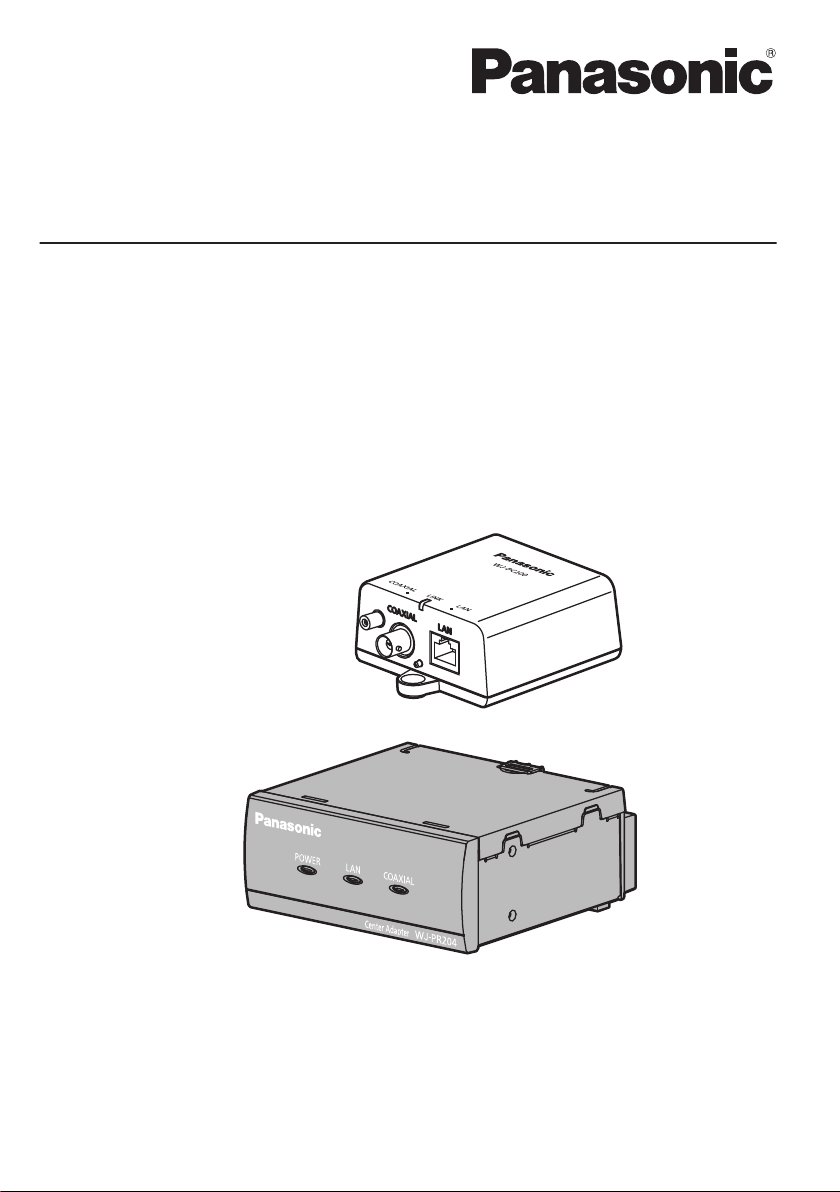
WJ-PC200
Operating Instructions
Coaxial - LAN Converter
Model No. WJ-PR204 / WJ-PR204E
RECEIVER (4-channel)
WJ-PR201 / WJ-PR201E
RECEIVER (1-channel)
WJ-PC200 / WJ-PC200E
CAMERA
WJ-PR204
Before attempting to connect or operate this product, please read these instructions carefully and
save this manual for future use.

Important information
Important information
WARNING:
• To prevent injury, this apparatus must be
securely attached to the floor/wall/ceiling in
accordance with the installation instructions.
•
To prevent fire or electric shock hazard, do not
expose this apparatus to rain or moisture.
•
The apparatus should not be exposed to dripping or splashing and no objects filled with liquids, such as vases, should be placed on the
apparatus.
• All work related to the installation of this prod
uct should be made by qualified service personnel or system installers.
• The installation shall be carried out in accor
dance with all applicable installation rules.
• The connections should comply with local
electrical code.
• The mains plug or an appliance coupler shall
remain readily operable.
-
-
CAUTION:
• Any changes or modifications not expressly
approved by the party responsible for compli
ance could void the user’s authority to operate
the equipment.
• The network camera is only intended for a con
nection to an ethernet or PoE network without
routing to the outside plant.
•
Before attempting to connect or operate this
product, please read the label on the bottom.
-
-
For U.S. and Canada:
WJ-PR204 / WJ-PR201 / WJ-PC200
For Europe and other countries:
WJ-PR204E / WJ-PR201E / WJ-PC200E
CAN ICES-3(A)/NMB-3(A)
For Canada
For U.S.A.
NOTE: This equipment has been tested and
found to comply with the limits for a Class A digital device, pursuant to Part 15 of the FCC Rules.
These limits are designed to provide reasonable
protection against harmful interference when the
equipment is operated in a commercial environment. This equipment generates, uses, and can
radiate radio frequency energy and, if not installed
and used in accordance with the instruction manual, may cause harmful interference to radio communications.
Operation of this equipment in a residential area
is likely to cause harmful interference in which
case the user will be required to correct the interference at his own expense.
FCC Caution: To assure continued compliance,
(example - use only shielded interface cables
when connecting to computer or peripheral
devices). Any changes or modifications not
expressly approved by the party responsible for
compliance could void the user’s authority to
operate this equipment.
The model number and serial number of this
product may be found on the surface of the
unit.
You should note the model number and serial
number of this unit in the space provided and
retain this book as a permanent record of your
purchase to aid identification in the event of
theft.
For U.S.A.
Model No.
Serial No.
We declare under our sole responsibility that the product
to which this declaration relates is in conformity with the
standards or other normative documents following the
provisions of Directives 2006/95/EC and 2004/108/EC.
Wir erklären in alleiniger Verantwortung, daß das Produkt,
auf das sich diese Erklärung bezieht, mit den folgenden
Normen oder normativen Dokumenten übereinstimmt.
Gemäß den Bestimmungen der Richtlinie 2006/95/EC
und 2004/108/EC.
Nous déclarons sous notre propre responsabilité que le
produit auquel se réfère la présente déclaration est conforme
aux normes spécifiées ou à tout autre document normatif
conformément aux dispositions des directives 2006/95/CE
et 2004/108/CE.
Nosotros declaramos bajo nuestra única responsabilidad
que el producto a que hace referencia esta declaración
está conforme con las normas u otros documentos
normativos siguiendo las estipulaciones de las directivas
2006/95/CE y 2004/108/CE.
Noi dichiariamo sotto nostra esclusiva responsabilità che
il prodotto a cui si riferisce la presente dichiarazione
risulta conforme ai seguenti standard o altri documenti
normativi conformi alle disposizioni delle direttive
2006/95/CE e 2004/108/CE.
Wij verklaren als enige aansprakelijke, dat het product
waarop deze verklaring betrekking heeft, voldoet aan de
volgende normen of andere normatieve documenten,
overeenkomstig de bepalingen van Richtlijnen 2006/95/
EC en 2004/108/EC.
Vi erklærer os eneansvarlige for, at dette produkt, som
denne deklaration omhandler, er i overensstemmelse
med standarder eller andre normative dokumenter i følge
bestemmelserne i direktivene 2006/95/EC og 2004/108/
EC.
Vi deklarerar härmed vårt fulla ansvar för att den produkt till
vilken denna deklaration hänvisar är i överensstämmelse
med de standarder eller andra normativa dokument som
framställs i direktiv nr 2006/95/EC och 2004/108/EC.
Ilmoitamme yksinomaisella vastuullamme, että tuote, jota
tämä ilmoitus koskee, noudattaa seuraavia standardeja
tai muita ohjeellisia asiakirjoja, jotka noudattavat
direktiivien 2006/95/EC ja 2004/108/EC säädöksiä.
Vi erklærer oss alene ansvarlige for at produktet som denne
erklæringen gjelder for, er i overensstemmelse med følgende
normer eller andre normgivende dokumenter som følger
bestemmelsene i direktivene 2006/95/EC og 2004/108/EC.
For Europe
For use only with power supply Panasonic,
UP0651S-57PB
2 Operating Instructions
Important information
WJ-PR204E/WJ-PR201E
For U.K.
FOR YOUR SAFETY PLEASE READ THE FOLLOWING TEXT
CAREFULLY.
This appliance is supplied with a moulded three pin mains plug for your
safety and convenience.
A 5 amp fuse is tted in this plug.
Should the fuse need to be replaced please ensure that the replacement
fuse has a rating of 5 amp and that it is approved by ASTA or BSI to
BS1362.
Check for the ASTA mark
fuse.
If the plug contains a removable fuse cover you must ensure that it is
retted when the fuse is replaced.
If you lose the fuse cover the plug must not be used until a replacement
cover is obtained.
A replacement fuse cover can be purchased from your local Panasonic
Dealer.
IF THE FITTED MOULDED PLUG IS UNSUITABLE FOR THE SOCKET
OUTLET IN YOUR HOME THEN THE FUSE SHOULD BE REMOVED
AND THE PLUG CUT OFF AND DISPOSED OF SAFELY.
THERE IS A DANGER OF SEVERE ELECTRICAL SHOCK IF THE CUT
OFF PLUG IS INSERTED INTO ANY 13 AMP SOCKET.
or the BSI mark on the body of the
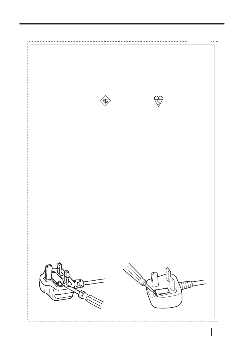
How to replace the fuse
The location of the differs according to the type of AC mains plug (gures A and B).
Conrm the AC mains plug tted and follow the instructions below.
Illustrations may differ from actual AC mains plug.
Open the fuse cover with a screwdriver and replace the fuse and close
or attach the fuse cover.
Figure A Figure B
Operating Instructions 3

Important safety instructions
Important safety instructions
1. Read these instructions.
2. Keep these instructions.
3. Heed all warnings.
4. Follow all instructions.
5. Do not use this apparatus near water.
6. Clean only with dry cloth.
not block any ventilation openings. Install in accordance with the manufacturer's
7. Do
instructions.
8. Do not install near any heat sources such as radiators, heat registers, stoves, or
other apparatus (including amplifiers) that produce heat.
9. Protect the power cord from being walked on or pinched particularly at plugs,
convenience receptacles, and the point where they exit from the apparatus.
10. Only use attachments/accessories specified by the manufacturer.
11. Use only with the cart, stand, tripod, bracket, or table specified by the manufacturer,
or sold with the apparatus. When a cart is used, use caution when moving the cart/
apparatus combination to avoid injury from tip-over.
S3125A
12. Unplug this apparatus during lightning storms or when unused for long periods of
time.
13. Refer all servicing to qualified service personnel. Servicing is required when the
apparatus has been damaged in any way, such as power
damaged, liquid has been spilled or objects have fallen into the apparatus, the
apparatus has been exposed to rain or moisture, does not operate normally, or has
been dropped.
4 Operating Instructions
-supply cord or plug is

Table of Contents
Table of Contents
1 Preface ........................................................................................................6
1.1 Main Features ...................................................................................................7
1.2 Introduction ......................................................................................................8
1.3 Other Information .............................................................................................9
1.4 Included Items ................................................................................................11
1.5 For Your Safety ...............................................................................................12
1.5.1 WARNING ......................................................................................................12
1.5.2 CAUTION .......................................................................................................15
1.6 General Precautions ......................................................................................15
1.7 Precautions for Installation ...........................................................................17
2 Parts and functions .................................................................................21
2.1 WJ-PR204/WJ-PR204E/WJ-PR201/WJ-PR201E (connects to the network
device) .............................................................................................................21
2.2 WJ-PC200/WJ-PC200E (connects to the camera) .......................................23
2.3 Understanding the Indicators .......................................................................24
3 Mounting the Unit ....................................................................................25
3.1 Mounting the camera side unit .....................................................................25
3.2 Mounting the receiver side unit to a Rack ...................................................26
4 Connecting the Unit .................................................................................30
4.1 Connection Conditions ..................................................................................30
4.1.1 When using a 1-channel Receiver Side Unit .................................................30
4.1.2 When using a 4-channel Receiver Side Unit .................................................32
4.2 Connections ....................................................................................................34
5 Maintenance Screen of coaxial - LAN converter ..................................41
5.1 Accessing the Maintenance Screen .............................................................42
5.1.1 Temporarily Changing the Computer’s IP Address ........................................42
5.1.2 Accessing the Maintenance Screen ...............................................................44
5.1.3 Maintenance Screen Overview ......................................................................46
5.2 Using the Maintenance Screen .....................................................................47
5.2.1 Confirming the coaxial - LAN converter’s Status ...........................................47
5.2.2 Updating the coaxial - LAN converter’s Firmware ..........................................49
5.2.3 Changing coaxial - LAN converter’s Settings .................................................50
6 Troubleshooting ......................................................................................51
6.1 Indicator Display Issues ................................................................................51
6.2 Transmission Speed ......................................................................................52
6.3 PoE+/PoE Issues ............................................................................................53
6.4 Other Issues ....................................................................................................53
7 Specifications ..........................................................................................54
Operating Instructions 5
1 Preface
1 Preface
This product is a coaxial - LAN converter consisting of the receiver side unit and the
camera side unit. It is capable of implementing long distance, high speed digital data
transmission on existing coaxial cables with low setup costs. With the built-in PoE
function, the unit is able to supply power to Panasonic network cameras, which
eliminates the need for installing power outlets for the cameras.
About notations
The following notations are used when describing the functions limited for specified
models.
The functions without the notations are supported by all models.
<Receiver side unit (4-channel)>
PR204
WJ-PR204/WJ-PR204E.
<Receiver side unit (1-channel)>
PR201
WJ-PR201/WJ-PR201E.
<Camera side unit>
WJ-PC200/WJ-PC200E.
Note
: The functions with these notation are available when using the model
: The functions with these notation are available when using the model
PC200
: The functions with these notation are available when using the model
• The Coaxial - LAN Converter (RECEIVER) is called the receiver side unit and
the LAN Converter (CAMERA) is called the camera side unit in this document.
RG-6/U coaxial cable
In this document coaxial cables with the following specifications are referred to as
RG-6/U coaxial cables.
Coaxial Cable
Type
RG-6/U
6 Operating Instructions
Less than 4
PR201
DC R/100 m
(328 feet) of Inner
Conductor
Maximum Cable
Length (for PoE
connections)
500 m (1,640 feet) 2.0 km (6,560 feet)
Maximum Cable
Length (for non-PoE
connections)

1 Preface
1.1 Main Features
To the receiver side, a 4ch model has been newly added in addition to the 1ch
model.
Up to 4 network cameras can be connected and used on a single receiver side unit.
PR204
Power over Ethernet Plus (PoE+) ready
The coaxial - LAN converter is compliant with PoE+ standards (IEEE802.3at) and
PoE+ cameras can be connected and used
Now we have a true space-saving system.
*1
.
Use over long distances
PR201
The coaxial - LAN converter can be used for distances of up to 300 m (984 feet) for
PoE+ connections and 500 m (1,640 feet) for PoE connections, and 2.0 km (6,560 feet)
for non-PoE+ connections. (When used with RG-6/U coaxial cable, and the loop
resistance is below 4 /100 m {328 feet} without additional joint parts.)
High-speed transmission
The coaxial - LAN converter is capable of transmission speeds of 35 Mbps or over for
*2
, and 45 Mbps or over for UDP connections.*2 (When used with RG-6/U coaxial
TCP
cable, and for distances under 2.0 km (6,560 feet)
PR204
).
PR201
, 500 m (1,640 feet)
No setup required
Connections can be established by simply connecting the coaxial cable to the coaxial
- LAN converter.
*1
There are limitations on the combinations of the cameras to be connected, the type of power supply and
transmission range to the receiver side units. Please see
cameras recommended by Panasonic, see the Panasonic support site
(http://security.panasonic.com/pss/security/support/info.html
*2
Transmission speed is the speed of transmission between the receiver side unit and the camera side unit.
Values may vary depending on the condition of the coaxial cable (for example, as the cable deteriorates over
time), network conditions, etc.
page 30 for details. For information on network
).
Operating Instructions 7

1 Preface
1.2 Introduction
About the user manuals
• Instruction
use and installation, installation and setup procedures, and other information.
The external appearance and other parts shown in this manual may differ from the
actual product within the scope that will not interfere with normal use due to
improvement of the product.
Trademarks
• Microsoft, Windows, Windows Vista, Windows Media, Internet Explorer, and ActiveX
are either registered trademarks or trademarks of Microsoft Corporation in the United
States and/or other countries.
• Microsoft product screen shot(s) reprinted with permission from Microsoft
Corporation.
• Linux is a registered trademark of Linus Torvalds in the United States and/or other
countries.
• All other trademarks identified herein are the property of their respective owners.
Manual (this document): Explains the safety precautions, instructions for
8 Operating Instructions

1 Preface
1.3 Other Information
About copyright and license
• Details
• Distributing, copying, disassembling, reverse compiling and reverse engineering of
Limitation of liability
THIS PUBLICATION IS PROVIDED “AS IS” WITHOUT WARRANTY OF ANY KIND,
EITHER EXPRESS OR IMPLIED, INCLUDING BUT NOT LIMITED TO, THE IMPLIED
WARRANTIES OF MERCHANTABILITY, FITNESS FOR ANY PARTICULAR
PURPOSE, OR NON-INFRINGEMENT OF THE THIRD PARTY'S RIGHT.
THIS PUBLICATION COULD INCLUDE TECHNICAL INACCURACIES OR
TYPOGRAPHICAL ERRORS. CHANGES ARE ADDED TO THE INFORMATION
HEREIN, AT ANY TIME, FOR THE IMPROVEMENTS OF THIS PUBLICATION AND/
OR THE CORRESPONDING PRODUCT (S).
Disclaimer of warranty
IN NO EVENT SHALL Panasonic System Networks Co., Ltd. BE LIABLE TO ANY
PARTY OR ANY PERSON, EXCEPT FOR REPLACEMENT OR REASONABLE
MAINTENANCE OF THE PRODUCT, FOR THE CASES, INCLUDING BUT NOT
LIMITED TO BELOW:
1. ANY LOSS OR DAMAGE, INCLUDING WITHOUT LIMITATION, DIRECT OR
2. ANY INCONVENIENCE, LOSS, OR DAMAGE CAUSED BY INAPPROPRIATE
3. ALL MALFUNCTIONS OR TROUBLES FROM UNAUTHORIZED DISASSEMBLE,
4. INCONVENIENCE OR ANY LOSS ARISING WHEN IMAGES ARE NOT
5. ANY PROBLEM, CONSEQUENTIAL INCONVENIENCE, OR LOSS OR DAMAGE,
6. ANY CLAIM OR ACTION FOR DAMAGES, BROUGHT BY ANY PERSON OR
7. LOSS OF REGISTERED DATA CAUSED BY ANY FAILURE.
about open source software is available by clicking the [Copyright] button on
the maintenance screen (page 46).
the software provided with this product (other than open source software) are all
expressly prohibited. In addition, exporting any software provided with this product
violating export laws is prohibited.
INDIRECT, SPECIAL, CONSEQUENTIAL OR EXEMPLARY, ARISING OUT OF OR
RELATING TO THE PRODUCT;
USE OR NEGLIGENT OPERATION OF THE USER;
REPAIR OR MODIFICATION OF THE PRODUCT BY THE USER, REGARDLESS
OF THE CAUSE OF THE MALFUNCTION OR TROUBLE;
DISPLAYED, DUE TO ANY REASON OR CAUSE INCLUDING ANY FAILURE OR
PROBLEM OF THE PRODUCT;
ARISING OUT OF THE SYSTEM COMBINED BY THE DEVICES OF THIRD
PARTY;
ORGANIZATION BEING A PHOTOGENIC SUBJECT, DUE TO VIOLATION OF
PRIVACY WITH THE RESULT OF THAT SURVEILLANCE-CAMERA'S PICTURE,
INCLUDING SAVED DATA, FOR SOME REASON, BECOMES PUBLIC OR IS
USED;
Operating Instructions 9

1 Preface
Network security
As you will use this unit connected to a network, your attention is called to the following
security risks.
Leakage or theft of information through this unit
Use of this unit for illegal operations by persons with malicious intent
Interference with or stoppage of this unit by persons with malicious intent
It is your responsibility to take precautions such as those described below to protect
yourself against the above network security risks.
Use this unit in a network secured by a firewall, etc.
•
•
If this unit is connected to a network that includes PCs, make sure that the system
is not infected by computer viruses or other malicious entities (using a regularly
updated anti-virus program, anti-spyware program, etc.).
• Protect your network against unauthorized access by restricting users to those who
log in with an authorized user name and password.
• Apply measures such as user authentication to protect your network against leakage
or theft of information, including image data, authentication information (user names
and passwords), alarm mail information, FTP server information and DDNS server
information.
• After the unit is accessed by the administrator, make sure to close the browser.
• Change the administrator password periodically.
• Do not install this unit in locations where this unit or the cables can be destroyed or
damaged by persons with malicious intent.
Security between the receiver side unit and camera side unit
• Data sent and received between camera side unit and receiver side unit employs
AES 128-bit encryption, however we cannot guarantee that data will not be
intercepted by a third party.
• The unit does not have a firewall feature. To prevent unauthorized external access
to the network, we recommend performing the following procedures.
– Setup security measures for the router and computers accessing the network.
10 Operating Instructions

1.4 Included Items
Confirm that the following items are included in the unit
WJ-PR204/WJ-PR204E/WJ-PR201/WJ-PR201E
• Operating Instructions (this document) (1 pc.)
• Warranty Card (1 pc.) WJ-PR204, WJ-PR201
• AC adapter (1 pc.)
• AC Cord (1 pc.) WJ-PR204, WJ-PR201
• AC Cord (2 pcs.)
• BNC Connector Cover (4 ch.) (1 pc.)
• BNC Connector Cover cap (3 pcs.)*2
• BNC Connector Cover (1 ch.) (1 pc.)
*1
WJ-PR204E, WJ-PR201E
PR204
PR204
PR201
• Screw (M2.6 10 mm {3/8 inches}) (2 pcs. of them, 1 for spare)
WJ-PC200/WJ-PC200E
• Operating Instructions (this document) (1 pc.)
• Warranty Card (1 pc.) WJ-PC200
• BNC Connector Cover (1 ch.) (1 pc.)
• Wood screw (4 20 mm {13/16 inches}) (3 pcs. of them, 1 for spare)
• Screw (M2.6 10 mm {3/8 inches}) (2 pcs. of them, 1 for spare)
• PoE incompatible cable (1 pc.)
• Cable coupler (used with the network cable) (1 pc.)
’s packaging.
1 Preface
*1
UK and other types of AC cords are included.
*2
BNC Connector Cover cap will be shipped with attached to the BNC connector cover (4 ch.).
Operating Instructions 11

1 Preface
1.5 For Your Safety
To
prevent severe injury and loss of life/property, read this section carefully before using
the unit to ensure proper and safe operation of your unit.
1.5.1 WARNING
Consult an authorized dealer for mounting.
• Experience and knowledge are required to perform mounting of the unit. Incorrect
mounting can cause damage to the unit, fire, electric shock, or injury. Make sure
to consult an authorized dealer for mounting.
Stop the operation immediately when something is wrong with this
product.
• When smoke goes up from the product, the smell of smoke comes from the
product, or the exterior of the product has deteriorated, continued use will cause
a fire or fall of the product resulting in injury, or damage to the product. In this
case, turn the power off immediately and contact qualified service personnel for
service.
Select an installation area that can support the total weight.
• Selecting an inappropriate installation surface may cause this product to fall down
or topple over, resulting in injury or accidents. Installation work shall be started
after sufficient reinforcement.
Do not install this product in locations subject to vibration.
• Loosening of mounting screws or bolts may cause a fall of the product resulting
in injury or accidents.
Turn the power off when do wiring of this product.
• Failure to observe this may cause electric shock. In addition, short circuit or wrong
wiring may cause fire.
Correctly perform all wiring.
• Short circuits in the wiring or incorrect wiring may cause fire or electrical shock.
Completely insert the power plug into the power outlet.
PR201
• Failure
Do not use damaged power plugs or power outlets.
to do so may cause electric shock and/or excessive heat resulting in a fire.
Regularly remove any dust, etc. from the power plug.
PR201
• Accumulated dust may cause an insulation defect from moisture, etc., resulting
in a fire. Disconnect the power plug, then wiping with a dry cloth.
PR204
PR204
12 Operating Instructions
1 Preface
Always hold the plug when unplugging the power cord.
PR201
• Otherwise, the cord may be damaged and result in a fire or electric shock.
The exclusively designed mount bracket shall be used.
PR201
• Failure to observe this may cause a drop resulting in injury or accidents. Use the
exclusively designed mount bracket for installation.
PR204
PR204
The screws and bolts must be tightened to the specified torque.
• Failure to observe this may cause a drop resulting in injury or accidents.
Periodic inspections shall be conducted.
• Rust on the metal parts or screws may cause a fall of the product resulting in injury
or accidents. Consult the dealer for the inspections.
Turn the power off when cleaning this product.
• Failure to observe this may cause injury.
Do not attempt to disassemble or modify this product.
• Failure to observe this may cause fire or electric shock. Consult the dealer for the
repair or inspections.
Do not insert any foreign objects.
• Fire or electrical shock may be caused if water or any foreign objects, such as
metal objects, enter inside the unit. Turn the power off immediately and contact
qualified service personnel for service.
Only use the included AC adapter.
• If other AC adapters are used, the voltage and positive/negative polarities may
differ and this may cause smoke to be emitted or fire.
PR204
PR201
Do not strike or give a strong shock to this product.
• Failure to observe this may cause fire or injury.
Place the unit securely on a stable, level surface.
• Serious damage and/or injury may result if the unit falls.
Do not install the unit in a dusty or moist place.
• This may result in electric shock or fire.
Do not use this product in an inflammable atmosphere.
• Failure to observe this may cause an explosion resulting in injury.
Operating Instructions 13

1 Preface
Avoid installing this product in the locations where salt damage occurs
or corrosive gas is produced.
• Otherwise, the mounting portions will deteriorate and accidents such as a fall of
the product may occur.
Do not damage the power cable.
• Do not damage, fabricate, twist, stretch, bundle, or forcibly bend the power cable.
Do not place heavy objects on it, and keep it away from heat sources. Use of a
damaged power cable may cause electric shock, short circuit, or fire. Consult the
dealer for repair.
PR204
Do not bring metal objects near the power outlet slots.
PR201
• This may result in electric shock or fire.
Do not use the included AC cord with other devices.
PR201
• This may result in electric shock or fire.
Only use the included AC cord.
• Using other AC cords may result in electric shock or fire.
PR204
PR201
PR204
PR204
PR201
Do not damage coaxial cables, insert objects into the conductor, or
connect coaxial cables with incomplete relays.
• If water or other objects enter the conductor, or coaxial cables with incomplete
relays are connected, it may result in electric shock or fire. Disconnect the power
line and contact an authorized service center if there is any damage to the coaxial
cables.
Do not forcibly pull on the cable.
• Doing so may result in a fire or electric shock.
Keep the BNC connector cover cap (an accessory that attaches to the
BNC connector cover) out of reach of young children to prevent them
from swallowing it by accident.
• Otherwise, they may swallow the cap by mistake. In this case, consult a doctor
immediately.
Do not damage existing wires or pipes when making holes for mounting
or wiring.
• This may result in earth leakage, electric shock, or fire.
Do not use the unit close to electronic devices such as medical
equipment.
• Otherwise, radio waves from the unit may affect electronic devices and cause of
an accident due to a malfunction.
14 Operating Instructions
1 Preface
Never touch the power plug with wet hands.
• This may result in electric shock.
PR204
PR201
Do not pour or wet the unit.
• This may result electric shock or fire. Turn the power off immediately and contact
qualified service personnel for service.
Do not touch the unit, ethernet cable, coaxial cable, AC cord, or power
plug during thunderstorms.
• This may result in electric shock.
Do not touch the core of the coaxial cable.
• This may result in electric shock. A maximum of DC 60 V is applied to the coaxial
cable.
1.5.2 CAUTION
If you do not use the unit for a long period of time, unplug the power
cable from the receptacle.
• Otherwise, it may result in a fire or electric shock.
PR204
Do not touch any metal edges with your hands.
• Doing so may cause injury.
Do not connect other devices to the BNC connector of the unit.
• This may damage the unit.
PR201
1.6 General Precautions
Follow the instructions written in Important safety instructions (see page 4) and 1.5 For
Your Safety (see page 12) together with the instructions written below.
1. Follow the following precautions in order to maintain product performance
over long periods of time.
• Do not use the unit in areas with high temperatures or humidity for long periods
of time. Use in these areas can degrade parts which can shorten the life-span of
the unit.
• Improve heat dissipation in the installation location and do not expose the unit to
direct heat from heating appliances.
2. The unit is intended for indoor use only and should not be mounted outdoors.
3. Exercise care not to let the unit get wet.
• Use the unit where it will not be subjected to water droplets or splashes.
4. The unit does not have a power switch.
• To disconnect this unit from the power supply, unplug the AC adapter power
cable or turn off the PoE power supply device. If installation requirements do not
PR204
PR201
Operating Instructions 15

1 Preface
allow the power to be quickly turned off, use a distribution panel with a circuit
breaker capable of disconnecting the power, or connect this unit to a power
source controller.
5. Handle this product with care.
• Do not drop this product, nor apply shock or vibration to the product. Failure to
observe this may cause trouble.
6. Power cable
PR204
PR201
• The attached AC adapter is designed exclusively for this unit. Do not use it for
other devices. In addition, do not use other AC adapters for this unit.
7. Cleaning this product body
• Be sure to turn off the power before cleaning. Failure to observe this may cause
injury.
Do not use benzine, thinner, alcohol, or any other types of solvents or detergents.
Otherwise, it may cause discoloration. When using a chemical cloth for cleaning,
read the caution provided with the chemical cloth product.
8. Cleaning stains from the unit
• Wipe stained areas with a damp soft cloth.
9. Radio disturbance
• This unit uses the same high-frequency signals as those used for amateur radio,
shortwave broadcasting, aviation radio, marine radio, and radio waves used for
astronomical observations and other similar purposes. If the unit is used near
radio equipment, it may interfere with these activities.
10. Equipment classification and power source indication label
• Refer to the indication label on the bottom side of this unit for the equipment
classification, power source, and other information.
: Direct current symbol
: Alternating current symbol
16 Operating Instructions

1.7 Precautions for Installation
Install the unit in accordance with electrical equipment technical standards.
Before beginning to install and connect the unit, check and prepare all necessary
peripheral equipment and cables. Turn off the power supply of the unit, camera, and
other components before connecting them.
All electrical wiring should be performed by a qualified electrician.
Consult an authorized dealer for installation.
Power supply
This product has no power switch. When turning off the power, disconnect the power
supply
AC cord or LAN cable can be easily disconnected.
1. The unit is intended for indoor use only
• The unit cannot be used outdoors. Do not install the unit in areas that are exposed
2. Do not install or use the unit near medical equipment
• High-frequency signals emitted from the unit may affect the operation of medical
3. Do not install or use the unit in the following locations:
– Locations where it may get wet from rain or water splash (including under the
– Locations where a chemical agent is used such as a swimming pool
– Locations subject to moisture or oil smoke such as a kitchen
– Locations that have a specific environment that is subject to an inflammable
– Locations where a radiation, an X-ray, a strong radio wave or a strong magnetic
– Locations with volcanic activity or hot springs where corrosive gas is produced,
– Locations where the temperature is not within the specified range (see
– Locations subject to vibrations, such as on vehicles, marine vessels, or above
– Locations subject to moisture or dust
– Locations subject to condensation as the result of severe changes in temperature
the
from
to direct sunlight for long periods of time, or areas near heaters or air conditioners.
Installing the unit in such areas may cause malfunctions and cause the unit to
change shape or color. Do not use the unit when they have been exposed to
water or moisture.
equipment and cause malfunctions.
eaves, etc.)
atmosphere or solvents
field is generated
locations where it may be damaged by briny air such as seashores
page 54)
product lines (This product is not designed for on-vehicle use.)
AC adapter (accessory) and the PoE device. Install the unit so that the
1 Preface
Operating Instructions 17
1 Preface
4. Precautions before receiver installations
PR204
PR201
• When mounting 3 to 4 connected receiver side units to the rack, use the following
bracket (locally procured).
– Rack mount bracket:
For WJ-PR204/WJ-PR201: BY-HCA10A
For WJ-PR204E/WJ-PR201E: BY-HCA10CE
• Available racks
– EIA standard rack or equivalent (third party)
EIA19 type
• Rack mounting screws
–M5 12 mm {15/32 inches} screws
5. Precautions before camera installations
PC200
• Use the screws with the specifications shown on page 25 when mounting the
camera side unit to a ceiling or wall. Screws are included with camera side unit.
Use screws that are appropriate for the material of the ceiling or wall.
• When mounting the camera side unit to a ceiling or wall (see page 25), do not
drive the screws into a soft material. Drive the screws into a secure, 25 mm
(1 inch) thick area of the ceiling or wall, such as a crossbeam, otherwise the
camera side unit may fall. If there is no crossbeam, place a board on the other
side of the ceiling or wall to make sure the camera side unit is securely mounted.
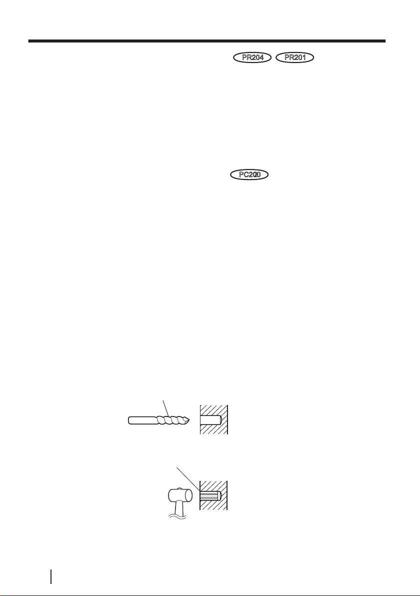
• When mounting a camera side unit on a concrete or mortar ceiling or wall, use
a drill and anchors (locally procured, body diameter 4 mm {3/16 inches}) and
make holes using the following procedure.
i.
Mark points where you are going to make holes (2 places) according to the
position of the camera side unit.
ii.
Make holes in the areas that you marked with an electric drill.
• Mortar ceilings break easily when drilling. Be careful of pieces of mortar
which may become loose and fall.
iii.
Insert the anchors (locally procured) into the holes and push them inside with
a hammer.
Drill for concrete (in case of tile, use a drill for tile)
Caulk to waterproof
• Mount the camera side unit to a secure area and make sure that the anchors and
screws are secured.
18 Operating Instructions
 Loading...