PANASONIC WJ-NV200K-G User Manual [ru]

0 (0)

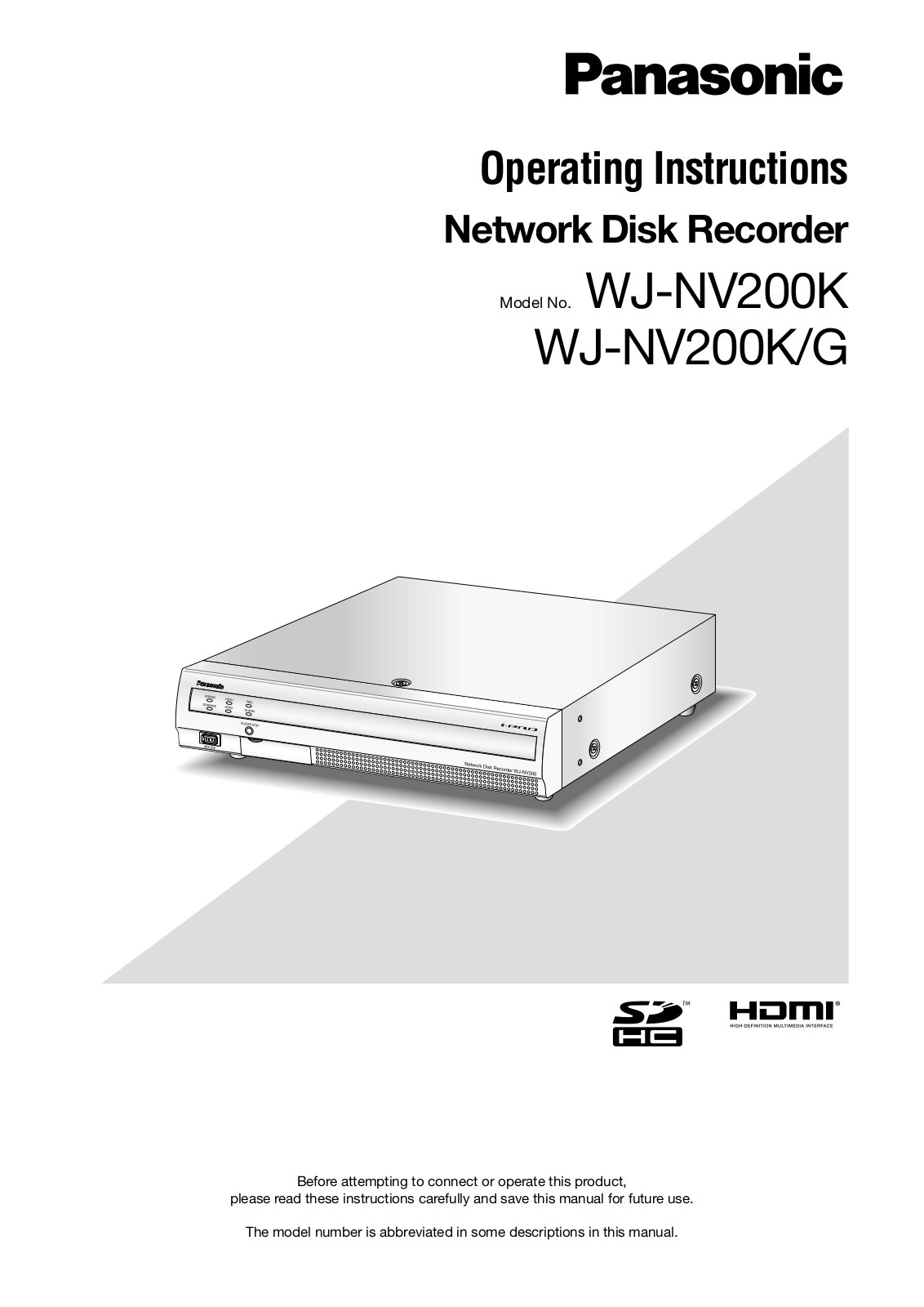
Operating Instructions

Network Disk Recorder

Model No. WJ-NV200K

WJ-NV200K/G

Before attempting to connect or operate this product,

please read these instructions carefully and save this manual for future use.

The model number is abbreviated in some descriptions in this manual.

CONTENTS

Preface........................................................................

4

About the user manuals..........................................

4

System requirements for a PC................................

4

Trademarks and registered trademarks..................

5

Abbreviations..........................................................

5

Restrictions when using this product.....................

6

Before using this product............................................

7

Face matching function..........................................

7

Motion detection (VMD) function............................

7

Time display of recorded images............................

7

Black screen displayed when playing recorded


images....................................................................

8

Recording operation (recording mode)...................

8

Event type...............................................................

8

Use an SD memory card.............................................

9

Operation window.....................................................

10

Ctrl (control) screen display..................................

10

Live monitor (monitor for display of live images


only)......................................................................

14

Basic operation.........................................................

15

Display the setup menu........................................

16

Logout...................................................................

16

Login operation at startup.........................................

17

Monitor live images...................................................

18

Operation panel....................................................

18

1-screen display (control screen only)..................

19

Display camera images on a full screen


(wide view)............................................................

21

Display or hide the camera title............................

22

Use digital zoom (control screen only)..................

23

Record images..........................................................

24

Record images (schedule recording)....................

24

Play recorded images...............................................

25

Playback operation panel.....................................

25

Play images from a designated point.......................

27

Play image recorded at a designated


time and date........................................................

27

Play the latest recorded image.............................

28

Playback by designating a timeline......................

29

Search and play........................................................

31

Play images selected from logs (log search)........

31

Search and play recorded images triggered by


motion detection (VMD search)............................

32

Play back copied images..........................................

35

Event function...........................................................

36

Event action..........................................................

36

Stop buzzer beeping.............................................

37

Cancel the alarm action........................................

38

Cancel the error action.........................................

38

Copy recorded images..............................................

39

Format SD memory card......................................

42

About the face matching function.............................

43

Face matching alarm actions................................

43

Reset face matching alarm ..................................

44

Display the face matching thumbnail again..........

44

Start/stop face matching actions manually..........

45

Operate the camera..................................................

46

Camera control panel............................................

46

Panning/Tilting......................................................

47

Zooming................................................................

48

Move to home position.........................................

48

Focus adjustment.................................................

48

Iris (brightness) adjustment...................................

49

Auto mode function of the camera.......................

49

Register camera preset positions.........................

50

Move camera preset positions..............................

50

Register home position.........................................

51

Execute auto back focus......................................

51

Configure the network settings.................................

52

Configure the network settings of the recorder....

52

Configure the network settings of the PC.............

52

Network security of the recorder..............................

55

The security function of the recorder....................

55

Enhance network security.....................................

55

Display the operation window...................................

57

About the operation window.....................................

58

Top Page...............................................................

58

Control panel........................................................

59

Camera selection panel........................................

60

Status display area...............................................

61

Download operation area......................................

62

[CAM] tab..............................................................

62

[HDD] tab..............................................................

63

Monitor live images from cameras............................

64

Display images on a 1-screen...............................

64

Display images on a 4-screen (multiscreen).........

65

Play recorded images...............................................

66

Play image recorded at a designated


time and date............................................................

68

Search and play recording events


(REC event search)....................................................

69

Motion detection search and playback


(VMD search).............................................................

71

Check a list of copied recorded images...................

73

Event function...........................................................

75

Event action..........................................................

75

Cancel the alarm action........................................

76

Cancel the error action.........................................

76

Copy recorded images..............................................

77

2

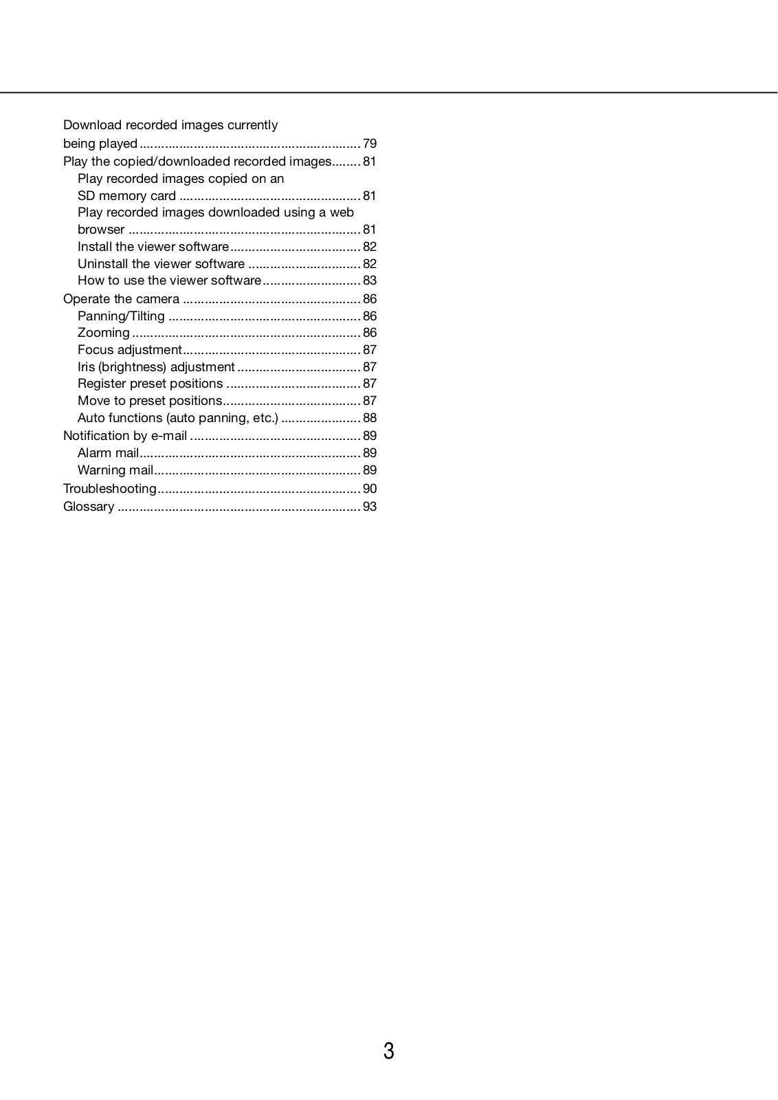
Download recorded images currently


being played..............................................................

79

Play the copied/downloaded recorded images........

81

Play recorded images copied on an


SD memory card...................................................

81

Play recorded images downloaded using a web


browser.................................................................

81

Install the viewer software....................................

82

Uninstall the viewer software................................

82

How to use the viewer software............................

83

Operate the camera..................................................

86

Panning/Tilting......................................................

86

Zooming................................................................

86

Focus adjustment.................................................

87

Iris (brightness) adjustment...................................

87

Register preset positions......................................

87

Move to preset positions......................................

87

Auto functions (auto panning, etc.).......................

88

Notification by e-mail................................................

89

Alarm mail.............................................................

89

Warning mail.........................................................

89

Troubleshooting........................................................

90

Glossary....................................................................

93

3

Preface

The network disk recorders WJ-NV200K and WJ-NV200K/G (hereinafter, recorders) are designed for use within a surveillance system, and record images/audio from up to 16 network cameras (hereinafter, cameras) on the hard disk drives. Up to 16 cameras can be registered.

This recorder supports HDMI (High-Definition Multimedia Interface) standard which allows displaying playback/ live images with superior quality when connecting to a high-definition monitor using an HDMI cable (option). It is possible to operate cameras from this recorder to display images from multiple cameras or switch cameras from which images are to be displayed, etc.

The recorders described in this installation guide are the models that are compatible as of July, 2010. Contact your dealer for further information.

* No hard disk drive is supplied with this recorder. For purchasing the hard disk drive, contact your dealer.

About the user manuals

There are 3 sets of operating instructions for the WJ-NV200K, WJ-NV200K/G as follows.

Installation Guide: Contains descriptions of how to install/connect this product and how to configure the required settings.

Operating Instructions (PDF)


(this document):

Contains descriptions of how to operate this product.


(Both operations using the interface on the product and using a PC via a network


are provided)

Quick Reference Guide:

Contains descriptions of how to operate functions frequently used.

Adobe® Reader® is required to read the PDF files on the provided CD-ROM. When Adobe® Reader® is not installed on the PC, download the latest Adobe® Reader® from the Adobe web site and install it.

Depending on descriptions, the model name of this recorder may be omitted as "NV200" in the manuals and on the setup.

The screens used in these operating instructions show the case in which WJ-NV200K is used and 16 cameras are connected.

Refer to "readme.txt" on the provided CD-ROM for further information about the optional dedicated software that receives and displays the event and error information, compatible cameras and their versions.

System requirements for a PC

It is recommended to operate this product using a PC that meets the following system requirements.

OS and web browser:

Windows® Internet Explorer® 8.0*1


(Microsoft® Windows® 7 Professional (32-bit)*2


Windows® Internet Explorer® 7.0


(Microsoft® Windows Vista® Business SP1 (32-bit))

CPU:

Intel® Core™ 2 Duo 2.66 GHz or faster

Memory:

1 GB or more

Monitor:

1 024 x 768 pixels or more, 24-bit True color or better

Network interface:

10BASE-T/100BASE-TX/1000BASE-T 1 port

Audio:

Sound card (When using the audio function)

Others:

CD-ROM drive: It is necessary to refer to the operating instructions on the provided


CD-ROM.


DirectX® 9.0c or later


Adobe® Reader®: It is necessary to refer to the operating instructions on the provided


CD-ROM.

*1 Windows® Internet Explorer® 8.0 (64-bit) is unavailable. *2 Windows® XP compatibility mode is unavailable.

4

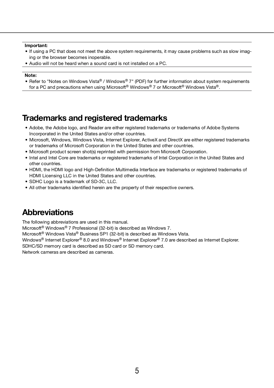
Important:

If using a PC that does not meet the above system requirements, it may cause problems such as slow imaging or the browser becomes inoperable.

Audio will not be heard when a sound card is not installed on a PC.

Note:

Refer to "Notes on Windows Vista® / Windows® 7" (PDF) for further information about system requirements for a PC and precautions when using Microsoft® Windows® 7 or Microsoft® Windows Vista®.

Trademarks and registered trademarks

Adobe, the Adobe logo, and Reader are either registered trademarks or trademarks of Adobe Systems

Incorporated in the United States and/or other countries.

Microsoft, Windows, Windows Vista, Internet Explorer, ActiveX and DirectX are either registered trademarks or trademarks of Microsoft Corporation in the United States and other countries.

Microsoft product screen shot(s) reprinted with permission from Microsoft Corporation.

Intel and Intel Core are trademarks or registered trademarks of Intel Corporation in the United States and other countries.

HDMI, the HDMI logo and High-Definition Multimedia Interface are trademarks or registered trademarks of

HDMI Licensing LLC in the United States and other countries.

SDHC Logo is a trademark of SD-3C, LLC.

All other trademarks identified herein are the property of their respective owners.

Abbreviations

The following abbreviations are used in this manual.

Microsoft® Windows® 7 Professional (32-bit) is described as Windows 7. Microsoft® Windows Vista® Business SP1 (32-bit) is described as Windows Vista.

Windows® Internet Explorer® 8.0 and Windows® Internet Explorer® 7.0 are described as Internet Explorer. SDHC/SD memory card is described as SD card or SD memory card.

Network cameras are described as cameras.

5

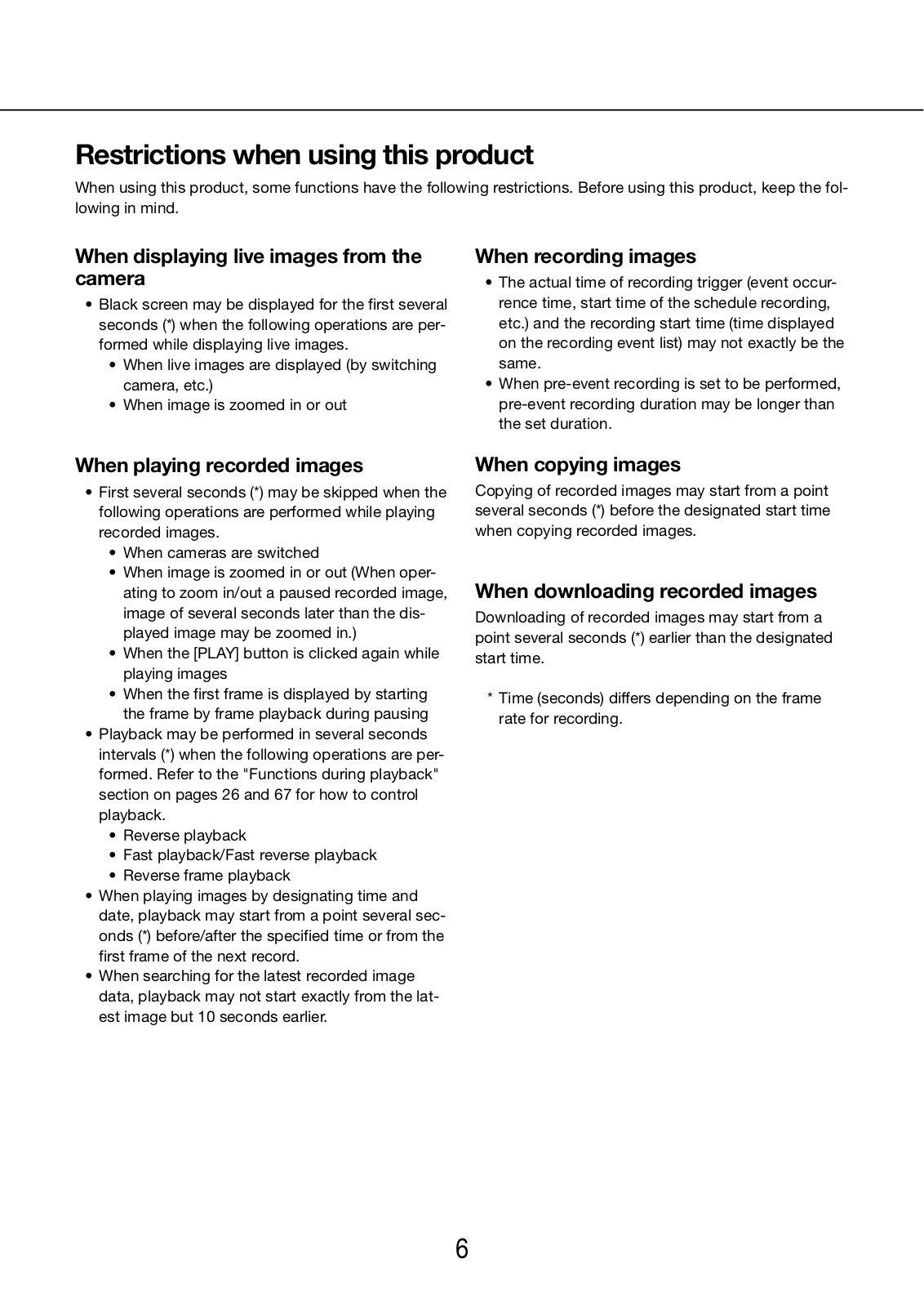
Restrictions when using this product

When using this product, some functions have the following restrictions. Before using this product, keep the following in mind.

When displaying live images from the camera

Black screen may be displayed for the first several seconds (*) when the following operations are performed while displaying live images.

When live images are displayed (by switching camera, etc.)

When image is zoomed in or out

When recording images

The actual time of recording trigger (event occurrence time, start time of the schedule recording, etc.) and the recording start time (time displayed on the recording event list) may not exactly be the same.

When pre-event recording is set to be performed, pre-event recording duration may be longer than the set duration.

When playing recorded images

First several seconds (*) may be skipped when the following operations are performed while playing recorded images.

When cameras are switched

When image is zoomed in or out (When operating to zoom in/out a paused recorded image, image of several seconds later than the displayed image may be zoomed in.)

When the [PLAY] button is clicked again while playing images

When the first frame is displayed by starting the frame by frame playback during pausing

Playback may be performed in several seconds intervals (*) when the following operations are performed. Refer to the "Functions during playback" section on pages 26 and 67 for how to control playback.

Reverse playback

Fast playback/Fast reverse playback

Reverse frame playback

When playing images by designating time and date, playback may start from a point several seconds (*) before/after the specified time or from the first frame of the next record.

When searching for the latest recorded image data, playback may not start exactly from the latest image but 10 seconds earlier.

When copying images

Copying of recorded images may start from a point several seconds (*) before the designated start time when copying recorded images.

When downloading recorded images

Downloading of recorded images may start from a point several seconds (*) earlier than the designated start time.

*Time (seconds) differs depending on the frame rate for recording.

6

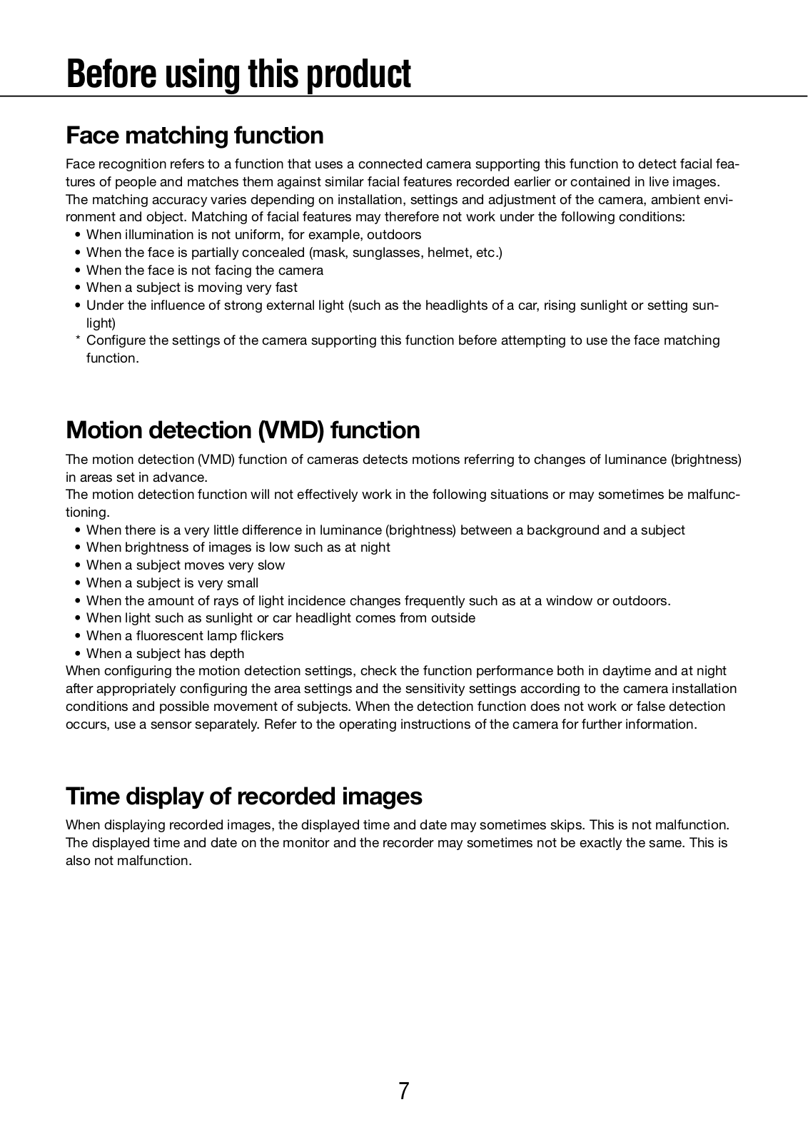
Before using this product

Face matching function

Face recognition refers to a function that uses a connected camera supporting this function to detect facial features of people and matches them against similar facial features recorded earlier or contained in live images. The matching accuracy varies depending on installation, settings and adjustment of the camera, ambient environment and object. Matching of facial features may therefore not work under the following conditions:

When illumination is not uniform, for example, outdoors

When the face is partially concealed (mask, sunglasses, helmet, etc.)

When the face is not facing the camera

When a subject is moving very fast

Under the influence of strong external light (such as the headlights of a car, rising sunlight or setting sunlight)

*Configure the settings of the camera supporting this function before attempting to use the face matching function.

Motion detection (VMD) function

The motion detection (VMD) function of cameras detects motions referring to changes of luminance (brightness) in areas set in advance.

The motion detection function will not effectively work in the following situations or may sometimes be malfunctioning.

When there is a very little difference in luminance (brightness) between a background and a subject

When brightness of images is low such as at night

When a subject moves very slow

When a subject is very small

When the amount of rays of light incidence changes frequently such as at a window or outdoors.

When light such as sunlight or car headlight comes from outside

When a fluorescent lamp flickers

When a subject has depth

When configuring the motion detection settings, check the function performance both in daytime and at night after appropriately configuring the area settings and the sensitivity settings according to the camera installation conditions and possible movement of subjects. When the detection function does not work or false detection occurs, use a sensor separately. Refer to the operating instructions of the camera for further information.

Time display of recorded images

When displaying recorded images, the displayed time and date may sometimes skips. This is not malfunction. The displayed time and date on the monitor and the recorder may sometimes not be exactly the same. This is also not malfunction.

7

Black screen displayed when playing recorded images

In the following cases, a black screen may be displayed during playing recorded images. However, this is not malfunction.

When changing cameras or screen patterns during playback or pausing

When skipping/reverse skipping during playback

When fast forwarding/reverse fast forwarding during playback

When the [Go to last] button is cliked during playback on a multiscreen

When going to the next recording event list by fast forwarding/reverse fast forwarding or skipping/reverse skipping during playback

When playback operation is affected by another operation (such as when receiving multiple alarms sequentially or when copying is being performed simultaneously)

Recording operation (recording mode)

It is possible to connect up to 16 cameras to the recorder and record images from them on the hard disk drives. The following recording operations are available.

Schedule recording:

Recording that is automatically performed at the designated time range on the desig-


nated day(s) of the week

Event recording:

Recording that is automatically performed when an event occurs (such as terminal


alarm/camera site alarm, etc.)

Important:

Recording may not be performed for around 3 seconds in the following cases. However, this is not a malfunction.

When the settings are changed and the setup menu is closed during recording

When the resolution, image quality or the recording rate is changed during recording

When event recording starts or ends during recording

Event type

The following event recording types are displayed in list form on the web browser:

SCH: Schedule recording

The following are detailed event recording types.

COM: Displayed when a command alarm occurred

TRM: Displayed when a terminal alarm occurred

SITE: Displayed when a camera site alarm occurred

FACE Displayed when a face matching alarm occurred

PRE: Pre-event recording

8

Use an SD memory card

Insert an SD memory card (option)

Step 1

Open the SDHC/SD memory card slot cover.

Pull the tab down.

SDHC/SD memory card slot cover

Step 2

Insert a SD memory card to the slot until it clicks. Hearing a click means that the card is properly inserted.

When inserting an SD memory card, confirm that the label on the SD memory card is upside and only the upper right corner of the card has different shape.

Step 3

Close the SDHC/SD memory card slot cover.

Note:

When removing the SD memory card from the slot, push the card until it clicks and pull it up straight.

9

Operation window

The recorder can be operated using the provided mouse connected to the mouse connection port on the front side of the recorder. When operating the recorder using a web browser, refer to "Configure the network settings" ( page 52)

Ctrl (control) screen display

The control screen is the default screen at startup. The main operations of the recorder are performed from this screen.

q

e

w


r


qImage display area

Displays images from the camera. ( Page 18)

wStatus display panel

Displays the statuses of the recorder. Also displays alarm/error status and remedies.

( Page 13)

eOperation panel

Used to switch between screens, to play back recordings, operate the camera and so on. Displays the current date and time. While summer time is activated, the time will be displayed with an asterisk (*).

r[Wide view] button

Switches the main monitor to wide view display.

10

PANASONIC WJ-NV200K-G User Manual

Wide view display

This view offers a large image display area, especially suited for monitoring live images. However, operations are restricted (no playback of recorded images).

w

qImage display area

Displays images from the camera. ( Page 18)

wStatus display panel

Displays the statuses of the recorder. Also displays alarm/error status and remedies.

( Page 16)

When clicking alarm button or error button, this panel may be displayed overlapped on the operation panel.

q

er

eOperation panel

Switches between screens and screen patterns. Displays the current date and time. While summer time is activated, the time will be displayed with an asterisk (*).

r[Ctrl screen] button

Switches the main monitor to control screen display.

Image display area

Displays live images and playback images on the control screen. Only live images can be displayed on the wide view screen.

Camera selection

Time & date

Camera title

frame


Camera title/time & date

The set camera title will be displayed. The display position can be selected from upper-left ("L-Upper"), lower-left ("L-Lower"), upper-right ("R-Upper") and lower-right ("R-Lower"). The default display position is "R-Upper". (Default: Upper right). Time and date will be displayed as set on the camera.

Camera selection frame

Displays the camera being operated. When using 1-screen/4-screen display ( pages 19 and 20), the cameras can be operated with the mouse.

11

Image display area

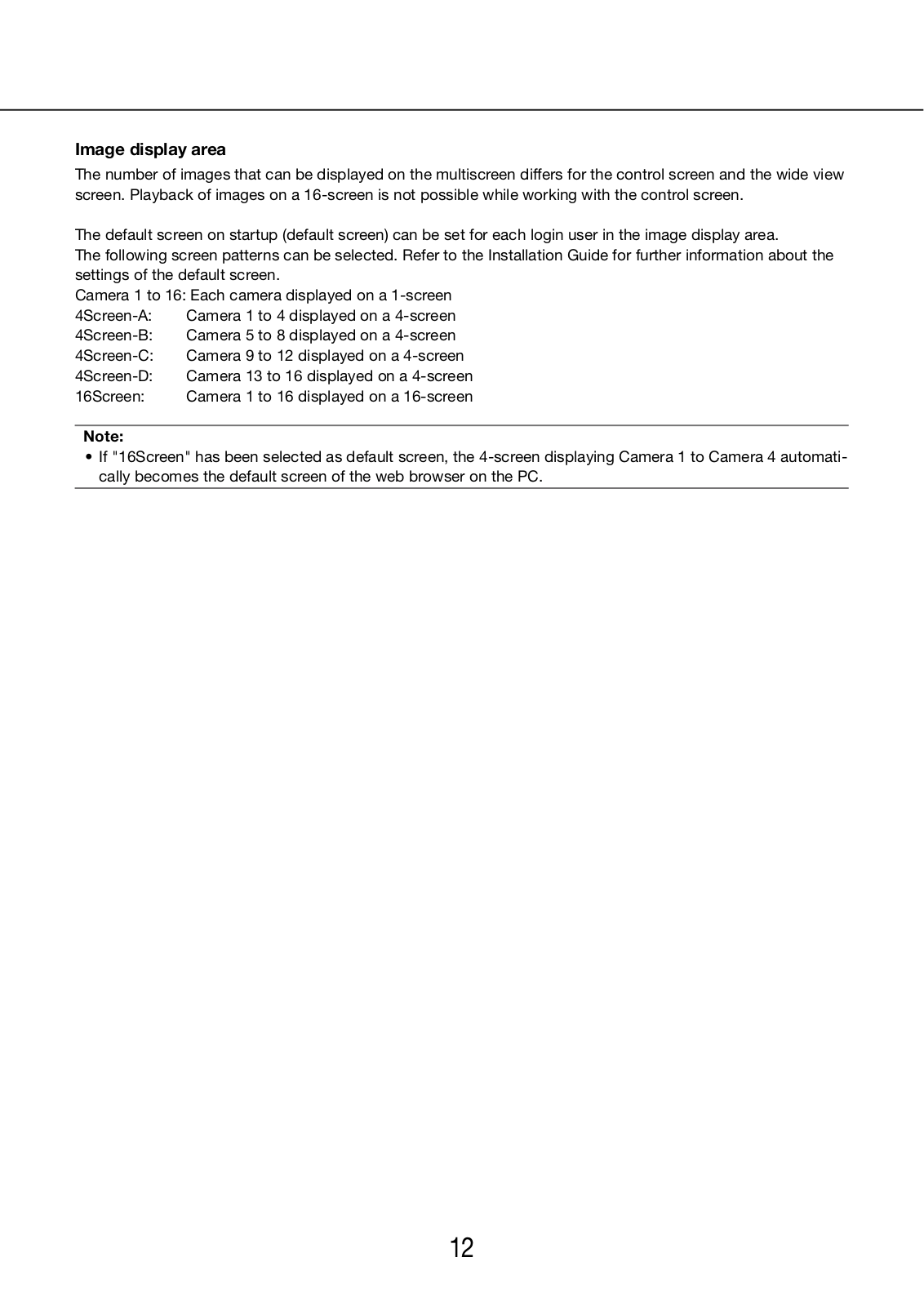
The number of images that can be displayed on the multiscreen differs for the control screen and the wide view screen. Playback of images on a 16-screen is not possible while working with the control screen.

The default screen on startup (default screen) can be set for each login user in the image display area.

The following screen patterns can be selected. Refer to the Installation Guide for further information about the settings of the default screen.

Camera 1 to 16: Each camera displayed on a 1-screen

4Screen-A:

Camera 1 to 4 displayed on a 4-screen

4Screen-B:

Camera 5 to 8 displayed on a 4-screen

4Screen-C:

Camera 9 to 12 displayed on a

4-screen

4Screen-D:

Camera 13 to 16 displayed on a 4-screen

16Screen:

Camera 1 to 16 displayed on a

16-screen

Note:

If "16Screen" has been selected as default screen, the 4-screen displaying Camera 1 to Camera 4 automatically becomes the default screen of the web browser on the PC.

12

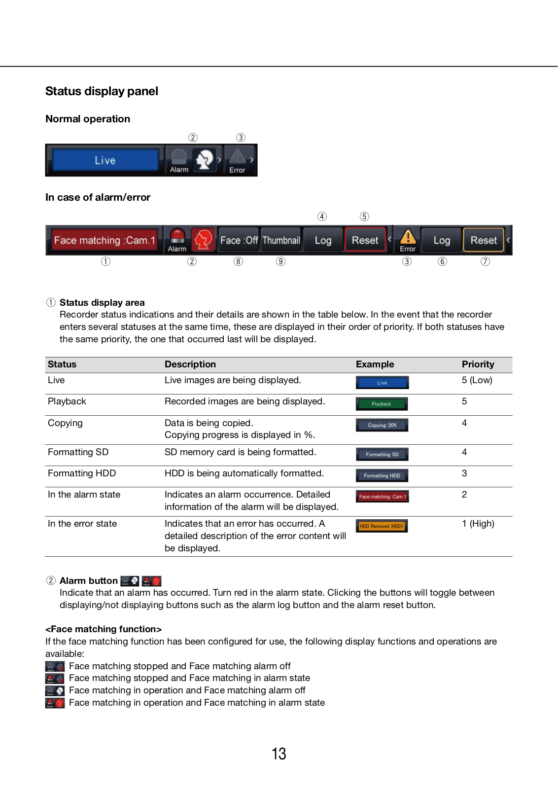
Status display panel

Normal operation

we

In case of alarm/error

r t

q

w

i

o

e y

u

qStatus display area

Recorder status indications and their details are shown in the table below. In the event that the recorder enters several statuses at the same time, these are displayed in their order of priority. If both statuses have the same priority, the one that occurred last will be displayed.

Status

Description

Example

Priority

Live

Live images are being displayed.


5

(Low)

Playback

Recorded images are being displayed.


5


Copying

Data is being copied.


4


Copying progress is displayed in %.


Formatting SD

SD memory card is being formatted.


4


Formatting HDD

HDD is being automatically formatted.


3


In the alarm state

Indicates an alarm occurrence. Detailed


2


information of the alarm will be displayed.


In the error state

Indicates that an error has occurred. A


1

(High)


detailed description of the error content will


be displayed.


wAlarm button

Indicate that an alarm has occurred. Turn red in the alarm state. Clicking the buttons will toggle between displaying/not displaying buttons such as the alarm log button and the alarm reset button.

<Face matching function>

If the face matching function has been configured for use, the following display functions and operations are available:

Face matching stopped and Face matching alarm off Face matching stopped and Face matching in alarm state Face matching in operation and Face matching alarm off

Face matching in operation and Face matching in alarm state

13

eError button

Indicates that an alarm has occurred. Turn yellow in the error state. Clicking the buttons will toggle between displaying/not displaying buttons such as the error log button and the error reset button.

rAlarm log display button

The alarm log display button is displayed on the operation panel of the control screen.

tAlarm reset button

Cancels the alarm action. Clickable only in the alarm state.

yError log button

The alarm log display button is displayed on the operation panel of the control screen.

uError reset button

Cancels the error action. Clickable only in the error state.

iFace matching start/stop button

Start/stop face matching actions manually. Face matching will resume when this button is clicked during pause. Face matching will stop when this button is clicked during face matching actions.

oFace display (Thumbnail) button

The latest face matching results are displayed on the operation panel of the control screen. ( Page 43)

Live monitor (monitor for display of live images only)

Important:

• Configuration and operation of the recorder from the live monitor is not possible.

Live images from a camera set up in advance can be displayed on a 1-screen on the live monitor. When several cameras are selected, camera images will be switched sequentially at the selected switching interval (sequence display Installation Guide).

Note:

Multiscreen display is not possible.

The camera title and time & date are not displayed on the live screen.

The time & date and camera also appear on the camera image displayed on the live monitor, but some characters may be cut off.

To display images, it is necessary to select the cameras to be displayed in the setup menu in advance. The recorder is not configured to display camera images by default.

Depending on the selected switching interval, a black screen may appear before camera images are displayed.

When the secret view function is selected, the image selected for the main monitor will not be displayed.

The image of a camera where an error has occurred will not be displayed.

14

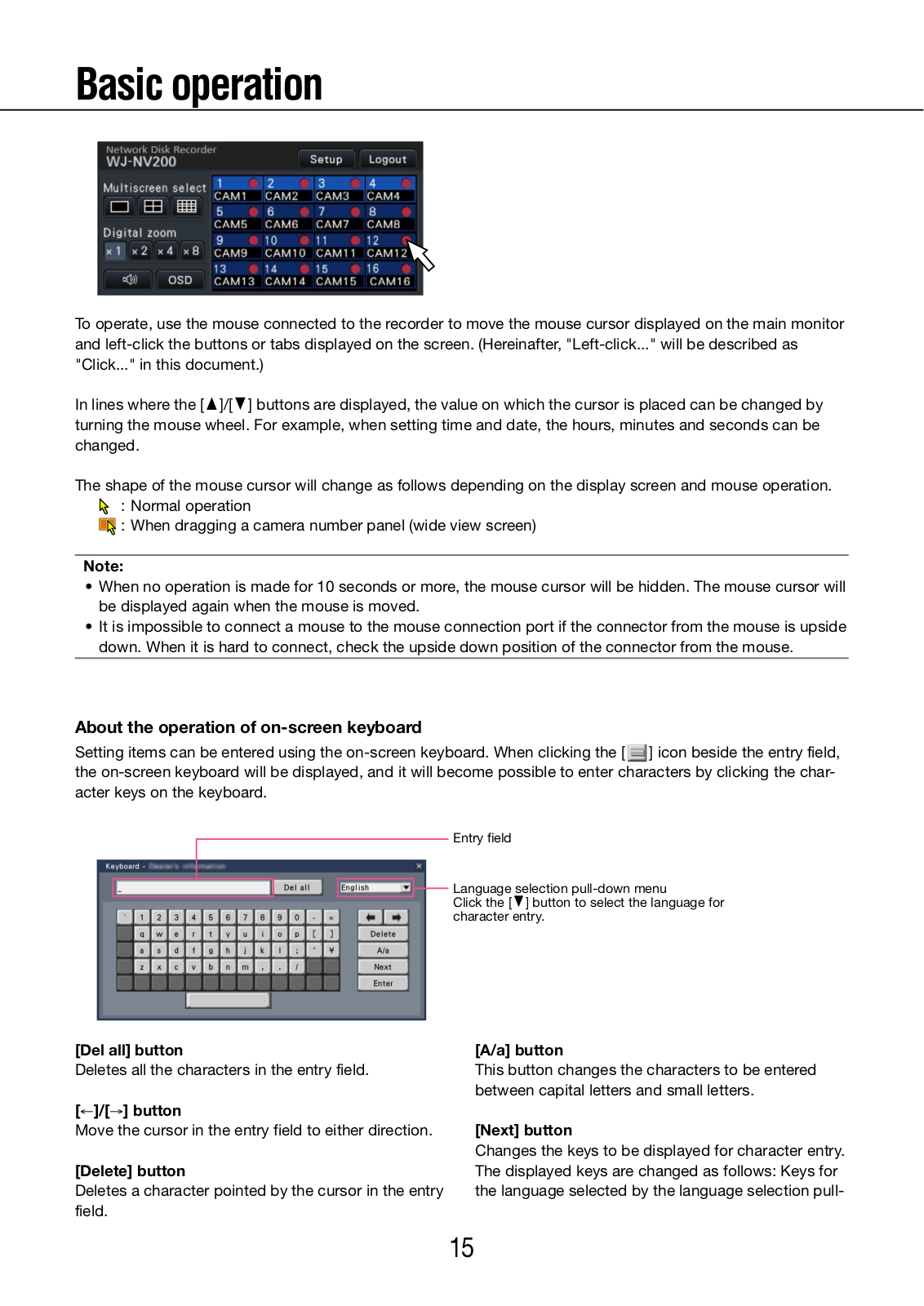
Basic operation

To operate, use the mouse connected to the recorder to move the mouse cursor displayed on the main monitor and left-click the buttons or tabs displayed on the screen. (Hereinafter, "Left-click..." will be described as "Click..." in this document.)

In lines where the [D]/[C] buttons are displayed, the value on which the cursor is placed can be changed by turning the mouse wheel. For example, when setting time and date, the hours, minutes and seconds can be changed.

The shape of the mouse cursor will change as follows depending on the display screen and mouse operation.

: Normal operation

: When dragging a camera number panel (wide view screen)

Note:

When no operation is made for 10 seconds or more, the mouse cursor will be hidden. The mouse cursor will be displayed again when the mouse is moved.

It is impossible to connect a mouse to the mouse connection port if the connector from the mouse is upside down. When it is hard to connect, check the upside down position of the connector from the mouse.

About the operation of on-screen keyboard

Setting items can be entered using the on-screen keyboard. When clicking the [ ] icon beside the entry field, the on-screen keyboard will be displayed, and it will become possible to enter characters by clicking the character keys on the keyboard.

Entry field

Language selection pull-down menu

Click the [C] button to select the language for character entry.

[Del all] button

Deletes all the characters in the entry field.

[]/[] button

Move the cursor in the entry field to either direction.

[Delete] button

Deletes a character pointed by the cursor in the entry field.

[A/a] button

This button changes the characters to be entered between capital letters and small letters.

[Next] button

Changes the keys to be displayed for character entry. The displayed keys are changed as follows: Keys for the language selected by the language selection pull-

15

down menu Combination characters Special characters

[Enter] button

Determines the entered characters and closes the onscreen keyboard.

Note:

Basic operations are also applied to the "Login" window and registration window for license.

Click the [×] button to close the window without determining the entered characters.

Depending on the windows for character entry such as the camera title, capital letters may be displayed on the on-screen keyboard instead of small letters.

Display the setup menu

Click the [Setup] button.

The setup menu will be displayed. For certain user levels, the login window will be displayed. Refer to the Installation Guide for further information about the settings.

Note:

If changes are made to the setup and the setup menu is closed while recording is underway, recording will be interrupted for approx. 3 seconds.

When changes are made to the setup, all users logged into the recorder will be forcibly logged out.

Logout

Click the [Logout] button. To log out, click the [OK] button in the confirmation window displayed.

16

Login operation at startup

When "Off" is selected for "Auto login", the recorder will start up in the logged out state after completing the system check.

When the operation window is displayed on the main monitor, enter a user name and password as follows:

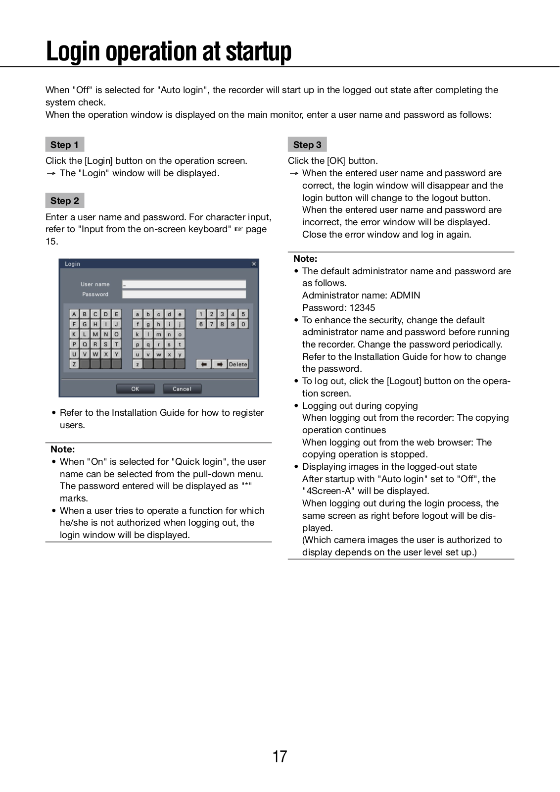
Step 1

Click the [Login] button on the operation screen. → The "Login" window will be displayed.

Step 2

Enter a user name and password. For character input, refer to "Input from the on-screen keyboard" page 15.

Refer to the Installation Guide for how to register users.

Note:

When "On" is selected for "Quick login", the user name can be selected from the pull-down menu. The password entered will be displayed as "*" marks.

When a user tries to operate a function for which he/she is not authorized when logging out, the login window will be displayed.

Step 3

Click the [OK] button.

When the entered user name and password are correct, the login window will disappear and the login button will change to the logout button.

When the entered user name and password are incorrect, the error window will be displayed. Close the error window and log in again.

Note:

The default administrator name and password are as follows.

Administrator name: ADMIN Password: 12345

To enhance the security, change the default administrator name and password before running the recorder. Change the password periodically. Refer to the Installation Guide for how to change the password.

To log out, click the [Logout] button on the operation screen.

Logging out during copying

When logging out from the recorder: The copying operation continues

When logging out from the web browser: The copying operation is stopped.

Displaying images in the logged-out state

After startup with "Auto login" set to "Off", the "4Screen-A" will be displayed.

When logging out during the login process, the same screen as right before logout will be displayed.

(Which camera images the user is authorized to display depends on the user level set up.)

17

Monitor live images

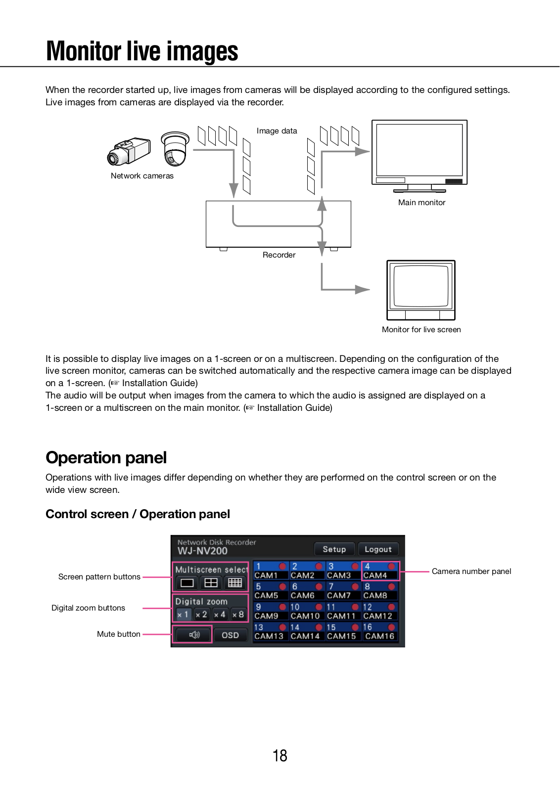
When the recorder started up, live images from cameras will be displayed according to the configured settings. Live images from cameras are displayed via the recorder.

Image data

Network cameras

Main monitor

Recorder

Monitor for live screen

It is possible to display live images on a 1-screen or on a multiscreen. Depending on the configuration of the live screen monitor, cameras can be switched automatically and the respective camera image can be displayed on a 1-screen. ( Installation Guide)

The audio will be output when images from the camera to which the audio is assigned are displayed on a 1-screen or a multiscreen on the main monitor. ( Installation Guide)

Operation panel

Operations with live images differ depending on whether they are performed on the control screen or on the wide view screen.

Control screen / Operation panel

Screen pattern buttons


Camera number panel


Digital zoom buttons

Mute button

18

Camera number panel

The camera number panel shows all camera-related information, such as registration status, camera title and recording status.

Camera number: (Character color)

White: Camera is registered. Gray: Camera is not registered.

(Background color)

Light blue: Image display area is displaying images

Gray: Recording not possible or camera not registered

Camera title: Shows the first 8 characters of the previously input camera title.

(Character color)

Same as camera number (Background color)

Red: In the alarm state

Gray: Camera is not registered.

Recording indicator: Lights red when recording is

being performed. Display of [] indicates a connection error.

Screen pattern buttons

The 1-screen/4-screen/16-screen buttons are displayed.

Digital zoom button

When displaying images on a 1-screen or 4-screen, the images can be enlarged/reduced ( page 23).

Mute button

Each click of this button toggles between mute and mute cancel of the camera audio.

1-screen display (control screen only)

To display live images on a 1-screen, take the following procedures.

Displaying images on a 1-screen

Step 1

Click the camera number panel of the desired image from the camera.

The background color of the selected camera number will turn aqua blue, and live images will be displayed.

Displaying images on a multiscreen

Step 1

Click the 1-screen button for the screen pattern.

The image display area will be displayed on a 1-screen.

Step 2

The background color of the selected camera number will turn aqua blue, and live images will be displayed.

Note:

Another way to display images on a 1-screen is to double-click the camera number panel of the camera to be selected in the image display area.

Double-clicking the camera number panel while displaying images is also possible to display an image on a 1-screen.

In the multiscreen display area, double-clicking the camera selection frame is also possible to display an image on a 1-screen.

The audio of the camera whose images are being displayed will be output.

Depending on the image size displayed, the audio may be delayed.

Each click of the mute button toggles between mute and mute cancel.

19

Display images from cameras on a multiscreen (control screen)

Live images from cameras can be displayed on a multiscreen (4-screen, 16-screen).

Step 1

Click the 4-screen or 16-screen button.

4-Screen button

Each click of a button switches to the next 4 screens in the sequence: camera 1 to 4 → camera 5 to 8 → camera 9 to 12 → camera 13 to 16.

16-Screen button

The images of camera 1 to 16 will be displayed.

Live images from cameras will be displayed on a multiscreen.

Note:

After having switched from multiscreen to

1-screen display, double-clicking the image display area will display the multiscreen displayed before switching screens.

It is also possible to switch the images displayed on the 4-screen by clicking the camera number panel with the 4-screen displayed. (When the panel of camera 5 is clicked with the 1- to 4-screen displayed, the images of camera 5 to 8 will be displayed)

The audio of the selected camera will be output.

Audio output may be delayed depending on the size of the displayed image.

20

Display camera images on a full screen (wide view)

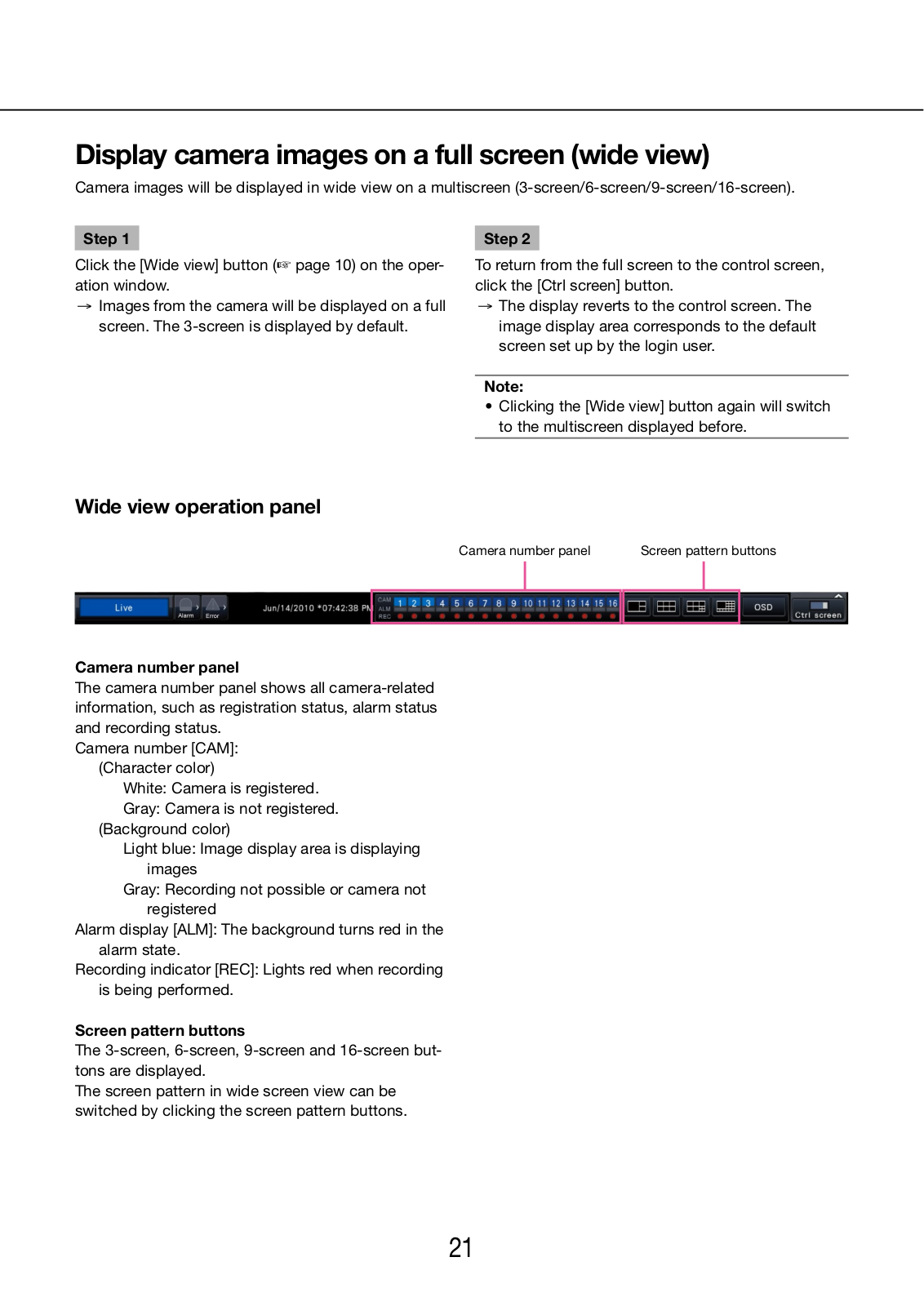
Camera images will be displayed in wide view on a multiscreen (3-screen/6-screen/9-screen/16-screen).

Step 1

Click the [Wide view] button ( page 10) on the operation window.

Images from the camera will be displayed on a full screen. The 3-screen is displayed by default.

Step 2

To return from the full screen to the control screen, click the [Ctrl screen] button.

The display reverts to the control screen. The image display area corresponds to the default screen set up by the login user.

Note:

Clicking the [Wide view] button again will switch to the multiscreen displayed before.

Wide view operation panel

Camera number panel

Screen pattern buttons


Camera number panel

The camera number panel shows all camera-related information, such as registration status, alarm status and recording status.

Camera number [CAM]: (Character color)

White: Camera is registered. Gray: Camera is not registered.

(Background color)

Light blue: Image display area is displaying images

Gray: Recording not possible or camera not registered

Alarm display [ALM]: The background turns red in the alarm state.

Recording indicator [REC]: Lights red when recording is being performed.

Screen pattern buttons

The 3-screen, 6-screen, 9-screen and 16-screen buttons are displayed.

The screen pattern in wide screen view can be switched by clicking the screen pattern buttons.

21

Change the camera display position on the screen

The default camera display positions are as follows:

3-screen


9-screen


9-screen


1


2

1

2

3

1

2


3


4

5

6


4

5


16-screen


3

1

2

3

4

5

6

7


6

7


8

9

10

8

9

11

12

13

14

15

16

It is possible to change the camera image by dragging & dropping the number of the camera assigned to the screen segment (1 to 16) onto the desired display position.

Note:

When a camera is assigned to a screen segment to which another camera is already assigned, the image of the camera originally assigned to that position will disappear.

The assigned camera position is retained even if the recorder is rebooted (note however that initializing the settings will also reset the camera positions to the defaults).

The audio of the camera assigned to the top left position will be output.

Audio output may be delayed depending on the size of the displayed image.

If "Mute" was selected on the control screen, no audio will be output.

Display or hide the camera title

It is possible to display/hide the camera title displayed on the monitor.

Step 1

Each time the [OSD] button is clicked, the camera title will be displayed/hidden.

Note:

The setting to display/hide the camera title will be retained until the power is turned off. Once the power is turned off and on again, the camera title will be displayed on system start.

22

Use digital zoom (control screen only)

Images on the 1-screen and 4-screen can be digitally zoomed. It is also possible to move the zoomed area within the displayed image.

Note:

Digital zoom is not available on the wide view screen and on the 9-screens/16-screens.

To use this function on the 4-screen, do so after first selecting the desired camera image. To select a camera, click the camera number panel or the camera image. Once a camera has been selected, the selection frame will be displayed around the camera image.

Step 1

Confirm that the image display area is displayed on the 1-screen or 4-screen.

(when displaying on the 4-screen, select the camera whose image is to be zoomed)

Step 2

Click the digital zoom buttons [×2] [×4] [×8].

The displayed image will be enlarged x2/x4/x8 centering on the center point of the screen.

Note:

Clicking a point in the zoomed image makes the clicked point the center of the image.

Step 3

Click the digital zoom button [x1] to cancel the digital zooming.

Note:

Digital zoom is automatically canceled by other operations such as selecting another camera or changing the screen pattern.

If "Enable camera control with mouse" on the camera control panel ( page 46) is not checked, the digital zoom factor can also be changed by placing the cursor on the image in the image display area and turning the mouse wheel. In this case, the point where the mouse cursor is positioned will become the zoom center.

23

Record images

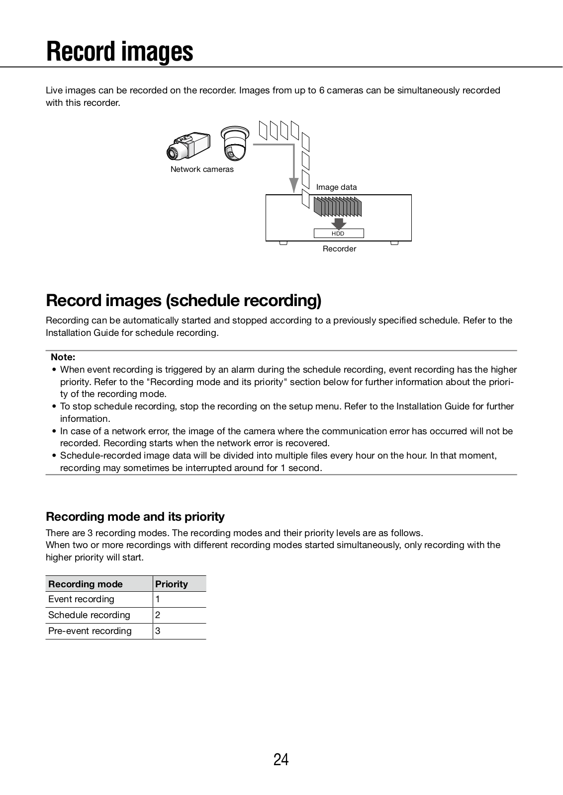
Live images can be recorded on the recorder. Images from up to 6 cameras can be simultaneously recorded with this recorder.

Network cameras

Image data

HDD

Recorder

Record images (schedule recording)

Recording can be automatically started and stopped according to a previously specified schedule. Refer to the Installation Guide for schedule recording.

Note:

When event recording is triggered by an alarm during the schedule recording, event recording has the higher priority. Refer to the "Recording mode and its priority" section below for further information about the priority of the recording mode.

To stop schedule recording, stop the recording on the setup menu. Refer to the Installation Guide for further information.

In case of a network error, the image of the camera where the communication error has occurred will not be recorded. Recording starts when the network error is recovered.

Schedule-recorded image data will be divided into multiple files every hour on the hour. In that moment, recording may sometimes be interrupted around for 1 second.

Recording mode and its priority

There are 3 recording modes. The recording modes and their priority levels are as follows.

When two or more recordings with different recording modes started simultaneously, only recording with the higher priority will start.

Recording mode

Priority


Event recording

1


Schedule recording

2


Pre-event recording

3


24

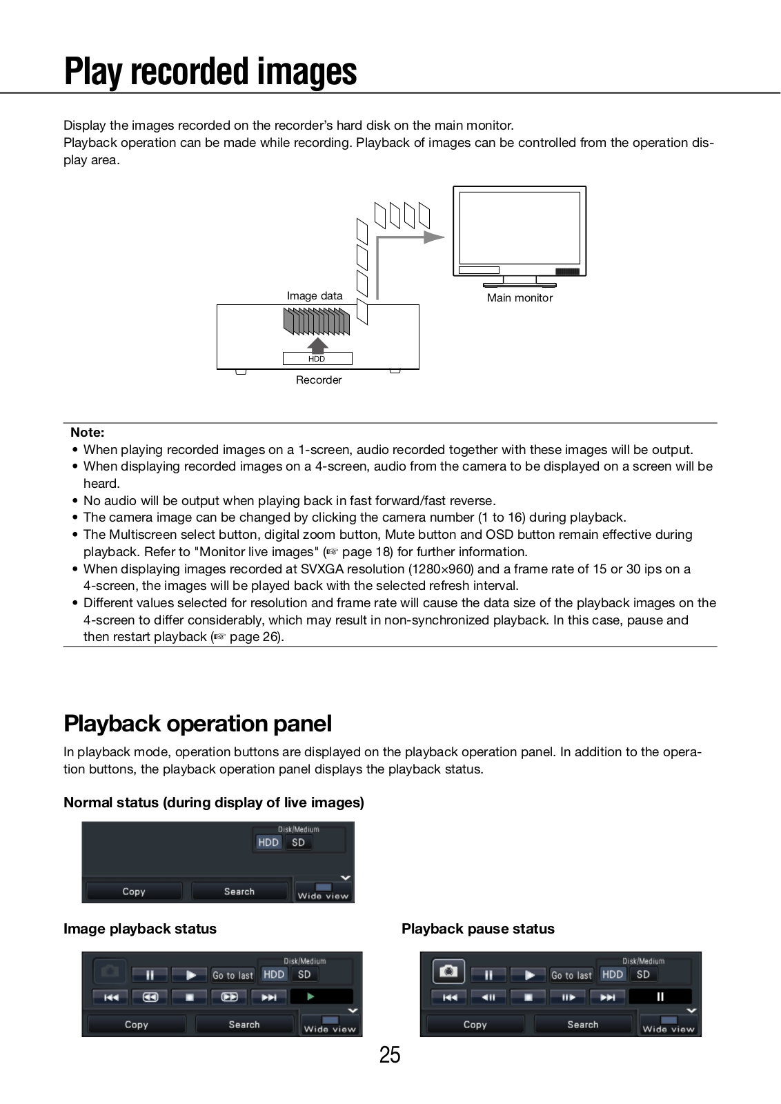
Play recorded images

Display the images recorded on the recorder’s hard disk on the main monitor.

Playback operation can be made while recording. Playback of images can be controlled from the operation display area.

Image data


Main monitor


HDD

Recorder

Note:

When playing recorded images on a 1-screen, audio recorded together with these images will be output.

When displaying recorded images on a 4-screen, audio from the camera to be displayed on a screen will be heard.

No audio will be output when playing back in fast forward/fast reverse.

The camera image can be changed by clicking the camera number (1 to 16) during playback.

The Multiscreen select button, digital zoom button, Mute button and OSD button remain effective during playback. Refer to "Monitor live images" ( page 18) for further information.

When displaying images recorded at SVXGA resolution (1280×960) and a frame rate of 15 or 30 ips on a

4-screen, the images will be played back with the selected refresh interval.

Different values selected for resolution and frame rate will cause the data size of the playback images on the

4-screen to differ considerably, which may result in non-synchronized playback. In this case, pause and then restart playback ( page 26).

Playback operation panel

In playback mode, operation buttons are displayed on the playback operation panel. In addition to the operation buttons, the playback operation panel displays the playback status.

Normal status (during display of live images)

Image playback status

Playback pause status

25

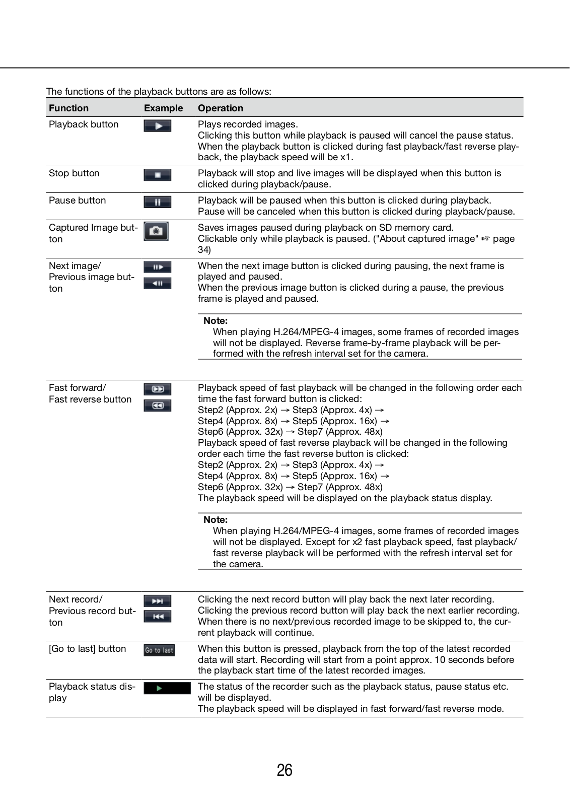
The functions of the playback buttons are as follows:

Function

Example

Operation


Playback button


Plays recorded images.


Clicking this button while playback is paused will cancel the pause status.


When the playback button is clicked during fast playback/fast reverse play-


back, the playback speed will be x1.


Stop button


Playback will stop and live images will be displayed when this button is


clicked during playback/pause.


Pause button


Playback will be paused when this button is clicked during playback.


Pause will be canceled when this button is clicked during playback/pause.


Captured Image but-


Saves images paused during playback on SD memory card.

ton


Clickable only while playback is paused. ("About captured image" page


34)

Next image/ Previous image button

When the next image button is clicked during pausing, the next frame is played and paused.

When the previous image button is clicked during a pause, the previous frame is played and paused.

Note:

When playing H.264/MPEG-4 images, some frames of recorded images will not be displayed. Reverse frame-by-frame playback will be performed with the refresh interval set for the camera.

Fast forward/

Playback speed of fast playback will be changed in the following order each

Fast reverse button

time the fast forward button is clicked:


Step2 (Approx. 2x)

→ Step3 (Approx. 4x) →


Step4 (Approx. 8x)

→ Step5 (Approx. 16x) →


Step6 (Approx. 32x) → Step7 (Approx. 48x)


Playback speed of fast reverse playback will be changed in the following


order each time the fast reverse button is clicked:


Step2 (Approx. 2x)

→ Step3 (Approx. 4x) →


Step4 (Approx. 8x)

→ Step5 (Approx. 16x) →


Step6 (Approx. 32x) → Step7 (Approx. 48x)


The playback speed will be displayed on the playback status display.

Note:

When playing H.264/MPEG-4 images, some frames of recorded images will not be displayed. Except for x2 fast playback speed, fast playback/ fast reverse playback will be performed with the refresh interval set for the camera.

Next record/ Previous record button

Clicking the next record button will play back the next later recording. Clicking the previous record button will play back the next earlier recording. When there is no next/previous recorded image to be skipped to, the current playback will continue.

[Go to last] button

When this button is pressed, playback from the top of the latest recorded


data will start. Recording will start from a point approx. 10 seconds before


the playback start time of the latest recorded images.


Playback status dis-

The status of the recorder such as the playback status, pause status etc.

play

will be displayed.


The playback speed will be displayed in fast forward/fast reverse mode.


26

Play images from a designated point

It is possible to start playback from a designated time and date or the latest recorded image.

Play image recorded at a designated time and date

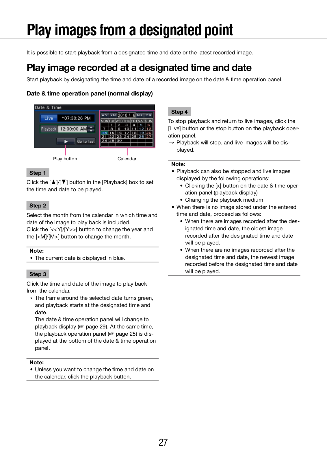
Start playback by designating the time and date of a recorded image on the date & time operation panel.

Date & time operation panel (normal display)

Play button

Calendar

Step 1

Click the [D]/[C] button in the [Playback] box to set the time and date to be played.

Step 2

Select the month from the calendar in which time and date of the image to play back is included.

Click the [<<Y]/[Y>>] button to change the year and the [<M]/[M>] button to change the month.

Note:

• The current date is displayed in blue.

Step 3

Click the time and date of the image to play back from the calendar.

The frame around the selected date turns green, and playback starts at the designated time and date.

The date & time operation panel will change to playback display ( page 29). At the same time, the playback operation panel ( page 25) is displayed at the bottom of the date & time operation panel.

Note:

Unless you want to change the time and date on the calendar, click the playback button.

Step 4

To stop playback and return to live images, click the [Live] button or the stop button on the playback operation panel.

Playback will stop, and live images will be displayed.

Note:

Playback can also be stopped and live images displayed by the following operations:

Clicking the [x] button on the date & time operation panel (playback display)

Changing the playback medium

When there is no image stored under the entered time and date, proceed as follows:

When there are images recorded after the designated time and date, the oldest image recorded after the designated time and date will be played.

When there are no images recorded after the designated time and date, the newest image recorded before the designated time and date will be played.

27

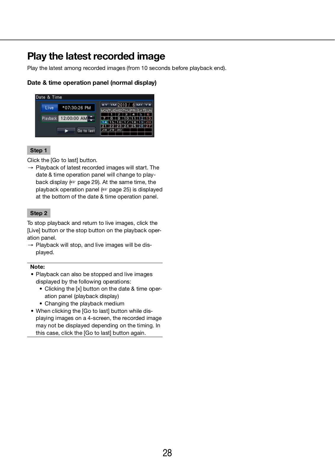
Play the latest recorded image

Play the latest among recorded images (from 10 seconds before playback end).

Date & time operation panel (normal display)

Step 1

Click the [Go to last] button.

Playback of latest recorded images will start. The date & time operation panel will change to playback display ( page 29). At the same time, the playback operation panel ( page 25) is displayed at the bottom of the date & time operation panel.

Step 2

To stop playback and return to live images, click the [Live] button or the stop button on the playback operation panel.

Playback will stop, and live images will be displayed.

Note:

Playback can also be stopped and live images displayed by the following operations:

Clicking the [x] button on the date & time operation panel (playback display)

Changing the playback medium

When clicking the [Go to last] button while displaying images on a 4-screen, the recorded image may not be displayed depending on the timing. In this case, click the [Go to last] button again.

28

Playback by designating a timeline

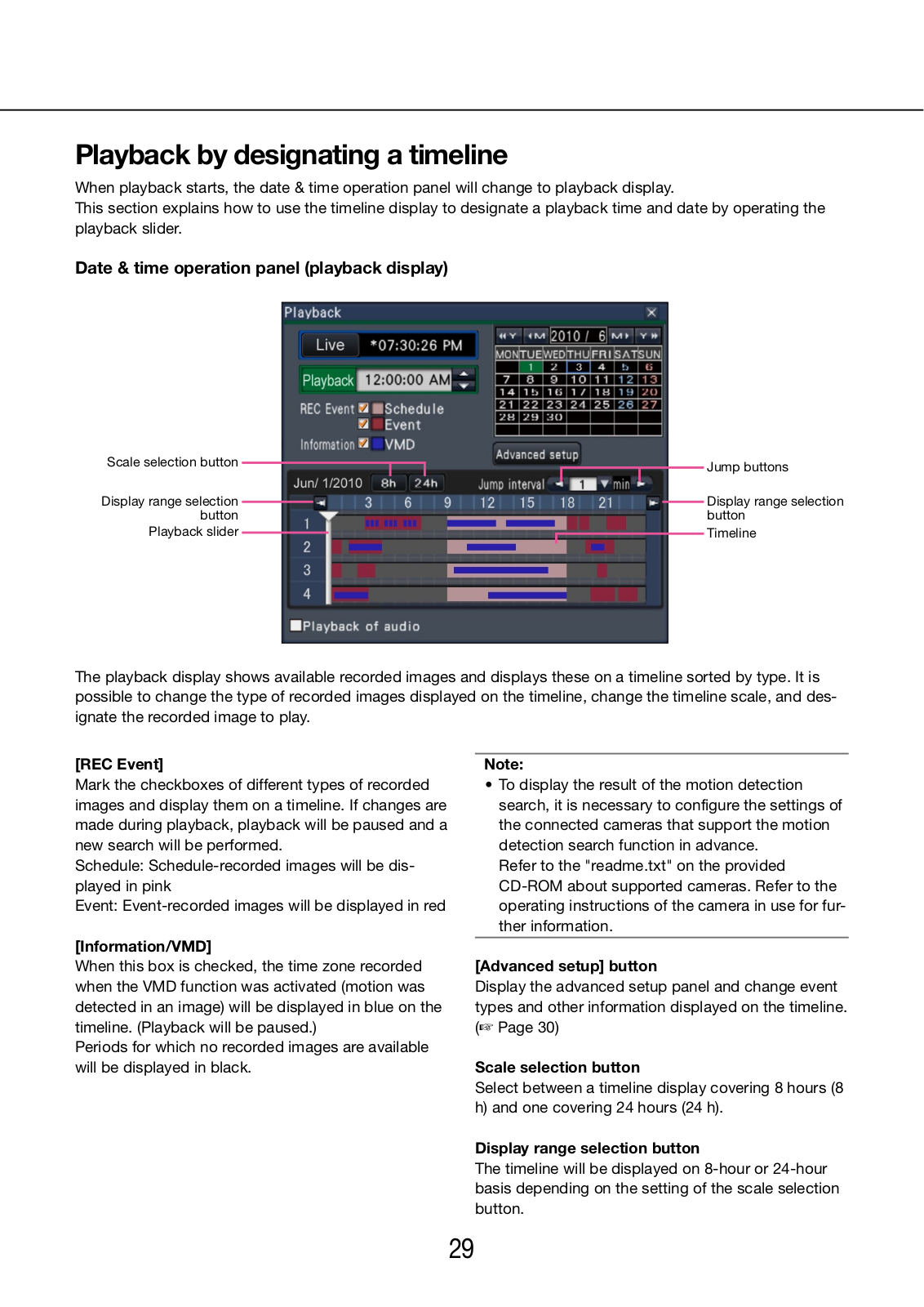
When playback starts, the date & time operation panel will change to playback display.

This section explains how to use the timeline display to designate a playback time and date by operating the playback slider.

Date & time operation panel (playback display)

Scale selection button


Jump buttons


Display range selection


Display range selection


button


button

Playback slider


Timeline


The playback display shows available recorded images and displays these on a timeline sorted by type. It is possible to change the type of recorded images displayed on the timeline, change the timeline scale, and designate the recorded image to play.

[REC Event]

Mark the checkboxes of different types of recorded images and display them on a timeline. If changes are made during playback, playback will be paused and a new search will be performed.

Schedule: Schedule-recorded images will be displayed in pink

Event: Event-recorded images will be displayed in red

[Information/VMD]

When this box is checked, the time zone recorded when the VMD function was activated (motion was detected in an image) will be displayed in blue on the timeline. (Playback will be paused.)

Periods for which no recorded images are available will be displayed in black.

Note:

To display the result of the motion detection search, it is necessary to configure the settings of the connected cameras that support the motion detection search function in advance.

Refer to the "readme.txt" on the provided CD-ROM about supported cameras. Refer to the operating instructions of the camera in use for further information.

[Advanced setup] button

Display the advanced setup panel and change event types and other information displayed on the timeline. ( Page 30)

Scale selection button

Select between a timeline display covering 8 hours (8 h) and one covering 24 hours (24 h).

Display range selection button

The timeline will be displayed on 8-hour or 24-hour basis depending on the setting of the scale selection button.

29

[Playback slider]

Displays the time during playback. Drag and drop the playback slider to a desired time to start playback from that time.

[Jump interval]/Jump buttons

Move the playback point by a given amount of time and play back from that point. Clicking the [<] / [>] buttons will move the playback point by the amount of time specified under [Jump interval].

Available ranges: 1min/ 3 min/ 5 min/ 10 min/ 15 min/ 30 min

[Playback of audio]

This item is displayed when the recorder is set up to lock in a camera with audio output. If this checkbox is marked, the audio associated with the displayed image will be output. ( Installation Guide)

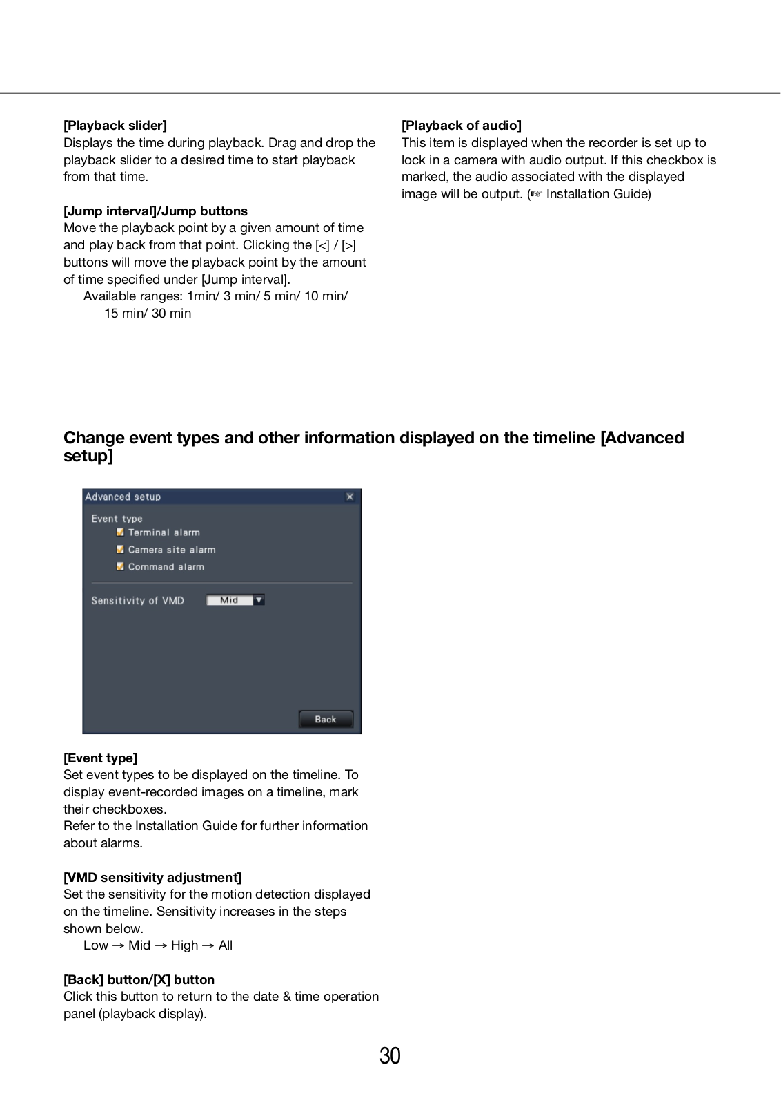
Change event types and other information displayed on the timeline [Advanced setup]

[Event type]

Set event types to be displayed on the timeline. To display event-recorded images on a timeline, mark their checkboxes.

Refer to the Installation Guide for further information about alarms.

[VMD sensitivity adjustment]

Set the sensitivity for the motion detection displayed on the timeline. Sensitivity increases in the steps shown below.

Low → Mid → High → All

[Back] button/[X] button

Click this button to return to the date & time operation panel (playback display).

30

Loading...
+ 67 hidden pages