

Page 1
LINK
RCV
SND
OPERATE
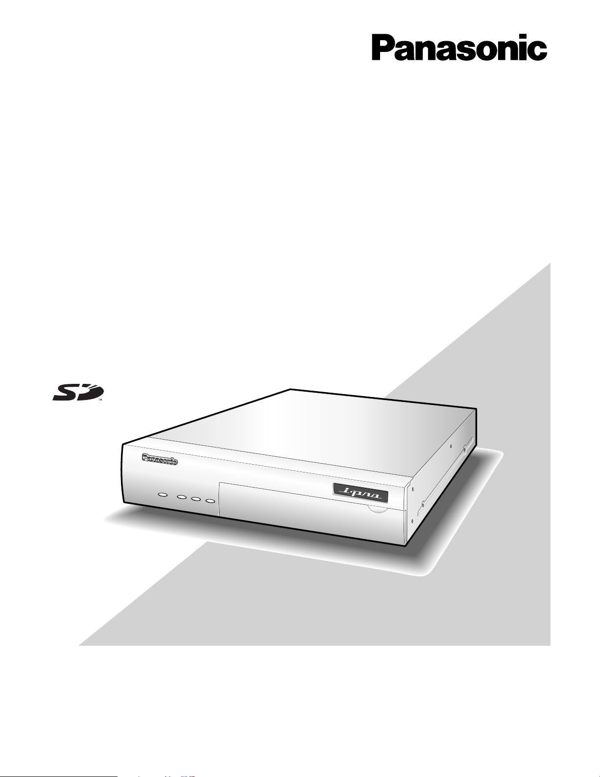
Network Interface Unit WJ-NT304
Network Interface Unit
Operating Instructions
Model No. WJ-NT304
Before attempting to connect or operate this product,
please read these instructions carefully and save this manual for future use.
Page 2
We declare under our sole responsibility that the product to which this
FUSE
declaration relates is in conformity with the standards or other normative
documents following the provisions of Directives EEC/73/23 and
EEC/89/336.
Wir erklären in alleiniger Verantwortung, daß das Produkt, auf das sich
diese Erklärung bezieht, mit der folgenden Normen oder normativen
Dokumenten übereinstimmt. Gemäß den Bestimmungen der Richtlinie
73/23/EEC und 89/336/EEC.
Nous déclarons sous note seule responsabilité que le produit auquel se
réfère la présente déclaration est conforme aux normes ou autres
documents normatifs conformément aux dispositions des directives
CEE/73/23 et CEE/89/336.
Nosotros declaramos bajo nuestra única responsabilidad que el producto
a que hace referencia esta declaración está conforme con las normas u
otros documentos normativos siguiendo las estipulaciones de las
directivas CEE/73/23 y CEE/89/336.
Noi dichiariamo sotto nostra esclusiva responsabilità che il prodotto a
cui si riferisce la presente dichiarazione risulta conforme ai seguenti
standard o altri documenti normativi conformi alle disposizioni delle
direttive CEE/73/23 e CEE/89/336.
WARNING:
• This apparatus must be earthed.
• Apparatus shall be connected to a mains socket outlet with a
protective earthing connection.
• The mains plug or an appliance coupler shall remain readily
operable.
• To prevent fire or electric shock hazard, do not expose this
apparatus to rain or moisture.
• The apparatus should not be exposed to dripping or splashing
and that no objects filled with liquids, such as vases, should be
placed on the apparatus.
• All work related to the installation of this product should be
made by qualified service personnel or system installers.
• The connections should comply with local electrical code.
CAUTION:
Before attempting to connect or operate this product, please
read the label on the bottom.
CAUTION
RISK OF ELECTRIC SHOCK
DO NOT OPEN
CAUTION: TO REDUCE THE RISK OF ELECTRIC SHOCK,
DO NOT REMOVE COVER (OR BACK).
NO USER-SERVICEABLE PARTS INSIDE.
REFER SERVICING TO QUALIFIED SERVICE PERSONNEL.
The lightning flash with arrowhead symbol,
within an equilateral triangle, is intended to
alert the user to the presence of uninsulated
"dangerous voltage" within the product's
enclosure that may be of sufficient magnitude to constitute a risk of electric shock to
persons.
The exclamation point within an equilateral
triangle is intended to alert the user to the
presence of important operating and maintenance (servicing) instructions in the literature accompanying the appliance.
Wij verklaren als enige aansprakelijke, dat het product waarop deze
verklaring betrekking heeft, voldoet aan de volgende normen of andere
normatieve documenten, overeenkomstig de bepalingen van Richtlijnen
73/23/EEC en 89/336/EEC.
Vi erklærer os eneansvarlige for, at dette produkt, som denne
deklaration omhandler, er i overensstemmelse med standarder eller
andre normative dokumenter i følge bestemmelserne i direktivene
73/23/EEC og 89/336/EEC.
Vi deklarerar härmed värt fulla ansvar för att den produkt till vilken
denna deklaration hänvisar är i överensstämmelse med
standarddokument, eller andra normativa dokument som framställs i
EEC-direktiv nr. 73/23 och 89/336.
Ilmoitamme yksinomaisella vastuullamme, että tuote, jota tämä ilmoitus
koskee, noudattaa seuraavia standardeja tai muita ohjeellisia asiakirjoja,
jotka noudattavat direktiivien 73/23/EEC ja 89/336/EE. säädöksiä.
Vi erklærer oss alene ansvarlige for at produktet som denne erklæringen
gjelder for, er i overensstemmelse med følgende normer eller andre
normgivende dokumenter som følger bestemmelsene i direktivene
73/23/EEC og 89/336/EEC.
Power disconnection. Unit with or without
ON-OFF switches have power supplied to
the unit whenever the power cord is inserted
into the power source; however, the unit is
operational only when the ON-OFF switch is
in the ON position. The power cord is the
main power disconnect for all units.
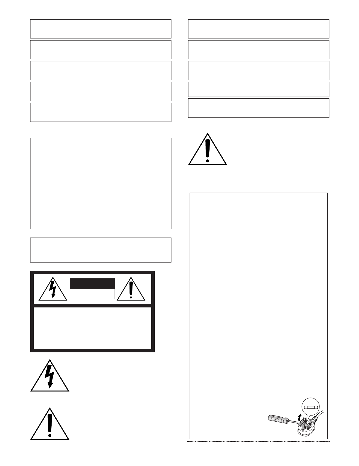
For U.K.
FOR YOUR SAFETY PLEASE READ THE FOLLOWING TEXT CAREFULLY.
This appliance is supplied with a moulded three pin mains plug for your
safety and convenience.
A 5 amp fuse is fitted in this plug.
Should the fuse need to be replaced please ensure that the replacement
fuse has a rating of 5 amp and that it is approved by ASTA or BSI to
BS1362.
Check for the ASTA mark
fuse.
If the plug contains a removable fuse cover you must ensure that it is
refitted when the fuse is replaced.
If you lose the fuse cover the plug must not be used until a replacement
cover is obtained.
A replacement fuse cover can be purchased from your local Panasonic
Dealer.
IF THE FITTED MOULDED PLUG IS UNSUITABLE FOR THE SOCKET OUTLET IN YOUR HOME THEN THE FUSE SHOULD BE
REMOVED AND THE PLUG CUT OFF AND DISPOSED OF SAFELY.
THERE IS A DANGER OF SEVERE ELECTRICAL SHOCK IF THE
CUT OFF PLUG IS INSERTED INTO ANY 13 AMP SOCKET.
If a new plug is to be fitted please observe the wiring code as shown
below.
If in any doubt please consult a qualified electrician.
WARNING: This apparatus must be earthed.
The wires in this mains lead are coloured in accordance with the following code.
As the colours of the wire in the mains lead of this appliance may not
correspond with the coloured markings identifying the terminals in your
plug, proceed as follows.
The wire which is coloured green-and-yellow must be connected to
the terminal in the plug which is marked with the letter E or by the earth
symbol
The wire which is coloured blue must be connected to the terminal in
the plug which is marked with the letter N or coloured black.
The wire which is coloured brown must be connected to the terminal
in the plug which is marked with the letter L or coloured red.
How to replace the fuse
Open the fuse compartment with
a screwdriver and replace the fuse
and fuse cover.
Green-and-yellow: Earth
Blue: Neutral
Brown: Live
I or coloured green or green-and-yellow.
H or the BSI mark G on the body of the
IMPORTANT
2
Page 3

The serial number of this product may be found on the surface of the unit.
You should note the serial number of this unit in the space
provided and retain this book as a permanent record of your
purchase to aid identification in the event of theft.
Model No.
Serial No.
For Canada
This Class A digital apparatus complies with Canadian
ICES-003.
For U.S.A
NOTE: This equipment has been tested and found to comply with the limits for a Class A digital device, pursuant to
Part 15 of the FCC Rules. These limits are designed to provide reasonable protection against harmful interference
when the equipment is operated in a commercial environment. This equipment generates, uses, and can radiate
radio frequency energy and, if not installed and used in
accordance with the instruction manual, may cause harmful
interference to radio communications.
Operation of this equipment in a residential area is likely to
cause harmful interference in which case the user will be
required to correct the interference at his own expense.
FCC Caution: To assure continued compliance, (example use only shielded interface cables when connecting to computer or peripheral devices). Any changes or modifications
not expressly approved by the party responsible for compliance could void the user’s authority to operate this equipment.
3
Page 4

Important Safety Instructions
1) Read these instructions.
2) Keep these instructions.
3) Heed all warnings.
4) Follow all instructions.
5) Do not use this apparatus near water.
6) Clean only with dry cloth.
7) Do not block any ventilation openings. Install in accordance with the manufacturer's instructions.
8) Do not install near any heat sources such as radiators, heat registers, stoves, or other apparatus (including amplifiers) that
produce heat.
9) Do not defeat the safety purpose of the polarized or grounding-type plug. A polarized plug has two blades with one wider
than the other. A grounding type plug has two blades and a third grounding prong. The wide blade or the third prong are
provided for your safety. If the provided plug does not fit into your outlet, consult an electrician for replacement of the
obsolete outlet.
10) Protect the power cord from being walked on or pinched particularly at plugs, convenience receptacles, and the point
where they exit from the apparatus.
11) Only use attachments/accessories specified by the manufacturer.
12) Use only with the cart, stand, tripod, bracket, or table specified by the manufacturer, or sold with the apparatus. When a
cart is used, use caution when moving the cart/apparatus combination to avoid injury from tip-over.
S3125A
13) Unplug this apparatus during lightning storms or when unused for long periods of time.
14) Refer all servicing to qualified service personnel. Servicing is required when the apparatus has been damaged in any way,
such as power-supply cord or plug is damaged, liquid has been spilled or objects have fallen into the apparatus, the
apparatus has been exposed to rain or moisture, does not operate normally, or has been dropped.
4
Page 5

Limitation of Liability
THIS PUBLICATION IS PROVIDED "AS IS" WITHOUT WARRANTY OF ANY KIND, EITHER EXPRESS OR IMPLIED,
INCLUDING BUT NOT LIMITED TO, THE IMPLIED WARRANTIES OF MERCHANTABILITY, FITNESS FOR ANY PARTICULAR PURPOSE, OR NON-INFRINGEMENT OF THE
THIRD PARTY’S RIGHT.
Disclaimer of Warranty
IN NO EVENT SHALL MATSUSHITA ELECTRIC INDUSTRIAL CO,.LTD. BE LIABLE TO ANY PARTY OR ANY PERSON,
EXCEPT FOR REPLACEMENT OR REASONABLE MAINTENANCE OF THE PRODUCT, FOR THE CASES, INCLUDING
BUT NOT LIMITED TO BELOW:
(1) ANY DAMAGE AND LOSS, INCLUDING WITHOUT LIM-
ITATION, DIRECT OR INDIRECT, SPECIAL, CONSEQUENTIAL OR EXEMPLARY, ARISING OUT OF OR
RELATING TO THE PRODUCT;
(2) PERSONAL INJURY OR ANY DAMAGE CAUSED BY
INAPPROPRIATE USE OR NEGLIGENT OPERATION
OF THE USER;
(3) UNAUTHORIZED DISASSEMBLE, REPAIR OR MODIFI-
CATION OF THE PRODUCT BY THE USER;
THIS PUBLICATION COULD INCLUDE TECHNICAL INACCURACIES OR TYPOGRAPHICAL ERRORS. CHANGES
ARE ADDED TO THE INFORMATION HEREIN, AT ANY
TIME, FOR THE IMPROVEMENTS OF THIS PUBLICATION
AND/OR THE CORRESPONDING PRODUCT (S).
(4) ANY PROBLEM, CONSEQUENTIAL INCONVENIENCE,
OR LOSS OR DAMAGE, ARISING OUT OF THE SYSTEM COMBINED BY THE DEVICES OF THIRD PARTY;
(5) ANY CLAIM OR ACTION FOR DAMAGES, BROUGHT
BY ANY PERSON OR ORGANIZATION BEING A PHOTOGENIC SUBJECT, DUE TO VIOLATION OF PRIVACY
WITH THE RESULT OF THAT SURVEILLANCE-CAMERA'S PICTURE, INCLUDING SAVED DATA, FOR SOME
REASON, BECOMES PUBLIC OR IS USED FOR THE
PURPOSE OTHER THAN SURVEILLANCE;
(6) LOSS OF REGISTERED DATA CAUSED BY ANY FAIL-
URE.
5
Page 6

Preface
Network Interface Unit WJ-NT304 is designed to capture images from analog cameras and compress the images in JPEG or
MPEG-4 files.
By connecting to a network (LAN) or the Internet, images and audio from the camera can be monitored on a PC via a
network.*
*1 It is necessary to configure the network settings of the PC and its network environment to monitor images and audio from
1
the camera on the PC.
It is also necessary that a web browser is installed on the PC.
Features
• Video input signals from up to 4 analog cameras can
be converted to stream files (JPEG or MPEG-4 format),
and a system can be established in which MPEG-4
images can be monitored while recording JPEG
images.
• Interactive communication with audio (transceiver type)
is available.
• Transceiver type communication is established by
transmitting and receiving audio when a user controls
the receiver button and transmission button interchangeably.
Transmitting and receiving audio are unavailable at the
same time.
• Panning/tilting platforms and lenses of combination
cameras (option) can be controlled with coaxial communication.
• The FTP backup function and recording of each log on
an optional SD memory card are available using the
featured SD memory card.*
2
*2 Compatible SD memory card is as follows.
(SDHC memory card is not supported.)
SD memory card manufactured by Panasonic (64 MB,
128 MB, 256 MB, 512 MB, 1 GB, 2GB)
6
Page 7

About These Operating Instructions
There are 2 sets of operating instructions for the WJ-NT304 as follows.
• Installation Guide (book, these operating instructions)
• Network operating instructions (PDF)
The "Installation Guide" contains descriptions of how to install and connect this unit, and how perform the required network settings.
Refer to the "Network Operating Instructions (PDF)" on the provided CD-ROM for descriptions of how to perform the unit settings and how to operate this unit. Adobe
®
Reader®is required to read these operating instructions (PDF).
System Requirements for a PC
CPU Pentium®4 2.4 GHz or faster
Memory: 512 MB or more
Network Interface: 10/100 Mbps Ethernet port x1
Audio Interface: Sound card (when activating audio)
Monitor: Image capture size: 1 024 x 768 pixels or more
Color: 24-bit True color or better
OS: Microsoft
Microsoft
Microsoft
OS Language: English, French, German*, Italian*, Spanish*, Chinese*, Russian*
Web Browser Microsoft
Microsoft
Other: CD-ROM Drive: It is necessary to read the operating instructions and use the software on the pro-
vided CD-ROM.
DirectX
Adobe
* PAL model only
®
Windows®2000 Professional SP4
®
Windows®XP Home Edition SP2
®
Windows®XP Professional SP2
®
Internet Explorer®6.0 SP2
®
Internet Explorer®6.0 SP1 only when using Windows®2000 Professional SP4
®
9.0c or later
®
Reader®: It is necessary to read the operating instructions on the provided CD-ROM.
Notes:
• When using a PC that does not meet the above requirements, displaying of images may become slow or the web browser
may become inoperable.
• Audio will not be activated if a sound card is not installed on a PC. Audio may be interrupted depending on the network
environment.
Trademarks and Registered Trademarks
• Microsoft, Windows, Internet Explorer, and DirectX are
either registered trademarks or trademarks of Microsoft
Corporation in the United States and/or other countries.
• Intel and Pentium are trademarks or registered trademarks of Intel Corporation or its subsidiaries in the
United States and other countries.
• Adobe and Reader are either registered trademarks or
trademarks of Adobe Systems Incorporated in the
United States and/or other countries.
• SD logo is a trademark.
• Other names of companies and products contained in
these operating instructions may be trademarks or registered trademarks of their respective owners.
7
Page 8

Network Security
As you will use this product connected to a network, your attention is called to the following security risks.
1. Leakage or theft of information through this product
2. Use of this product for illegal operations by persons with malicious intent
3. Interference with or stoppage of this product by persons with malicious intent
It is your responsibility to take precautions such as those described below to protect yourself against the above network security risks.
• Use this product in a network secured by a firewall, etc.
• If this product is connected to a network that includes PCs, make sure that the system is not infected by computer viruses
or other malicious entities (using a regularly updated anti-virus program, anti-spyware program, etc.).
• Protect your network against unauthorized access by restricting users to those who log in with an authorized user name
and password.
• Apply measures such as user authentication for the servers and the connected devices to protect your network against
leakage or theft of information, including image data, authentication information (user names and passwords), alarm mail
information, FTP server information, etc.
8
Page 9

CONTENTS
Important Safety Instructions ...................................................................................................................... 4
Limitation of Liability ................................................................................................................................... 5
Disclaimer of Warranty ............................................................................................................................... 5
Preface ....................................................................................................................................................... 6
Features ..................................................................................................................................................... 6
About These Operating Instructions ........................................................................................................... 7
System Requirements for a PC .................................................................................................................. 7
Trademarks and Registered Trademarks ................................................................................................... 7
Network Security ........................................................................................................................................ 8
Precautions ................................................................................................................................................. 10
Major Operating Controls and Their Functions ........................................................................................... 12
■ Front view ............................................................................................................................................. 12
■ Rear view .............................................................................................................................................. 13
Rack Mounting ............................................................................................................................................ 14
Connection Example .................................................................................................................................. 15
■ When connecting to a network using a PoE device (hub) .................................................................... 15
■ When connecting with a PC directly ..................................................................................................... 15
Insert/Remove an SD Memory Card .......................................................................................................... 16
■ How to insert an SD memory card ........................................................................................................ 16
■ How to remove the SD memory card ................................................................................................... 16
Configure the Network Settings .................................................................................................................. 17
■ Install the software ................................................................................................................................ 17
■ Uninstall the software ........................................................................................................................... 17
■ Configure the network settings of the unit using the Panasonic IP setting software ............................ 17
Troubleshooting .......................................................................................................................................... 18
Specifications ............................................................................................................................................. 19
Standard Accessories ................................................................................................................................. 19
9
Page 10

Precautions
• Do not block the ventilation opening or slots on the
cover.
To prevent the apparatus from overheating, place it at
least 5 cm {2 inches} away from the wall.
• Do not drop metallic parts through slots.
This could permanently damage the apparatus. Turn
the power off immediately and contact qualified service
personnel for service.
• Do not attempt to disassemble the apparatus.
To prevent electric shock, do not remove screws or
covers.
There are no user-serviceable parts inside. Contact
qualified service personnel for maintenance.
• Do not expose the apparatus to water or moisture.
Do not try to operate it in wet areas.
Take immediate action if the apparatus gets wet. Turn
the power off and refer servicing to qualified service
personnel. Moisture can damage the apparatus and
also cause electric shocks.
• Built-in backup battery
Before the first use, charge the built-in backup battery
(lithium battery) by turning on the power for 48 hours or
more. If it is not charged enough, in a case where the
power goes down, the internal clock may keep bad
time or the operative condition may be different to that
before the electric power failure.
The built-in battery life is approximately 5 years as an
indication of replacement. (This is just an indication of
replacement. We are not providing any guarantee of the
built-in battery lifetime. Replacement cost of the built-in
battery is not covered by the warranty even if it needs
to be done within the warranty period.) Ask the shop
where you purchased the unit when replacement of the
battery is required.
Use this product for indoor use only.
Do not expose this product to direct sunlight for hours and
do not install the product near a heater or an air conditioner. Otherwise, it may cause deformation, discoloration and
malfunction. Keep this product away from water.
To continue using with stable performance
• Parts of this product may deteriorate and it may shorten
the lifetime of this product when using in locations subject to high temperatures and high humidity. Do not
expose the product to direct heat such as from a
heater.
• Use this product at temperature within 5 °C to 35 °C
{41 °F to 95 °F} and humidity below 90%. (When using
this product without turning the power off)
The input power source for this apparatus is 120 V AC,
50 Hz/60 Hz.
Use only the supplied power cord or AC adapter.
Use the power cord that is suited to your locality.
Handle the appliance with care.
Do not strike or shake, as this may damage the product.
Failure to observe this may cause trouble.
About the PC monitor
When displaying the same image on the PC monitor for a
long time, the PC monitor may be damaged. It is recommended to use a screen-saver.
When an error is detected, the unit will restart automatically.
This unit will restart when detecting an error caused by any
reason. The unit will be inoperable for around 2 seconds
after the restart just as when the power is turned on.
About SD memory card
• Before inserting a SD memory card into the SD memory
card slot, turn the power of the unit off. Otherwise, it
may cause malfunction or damage data recorded on
the SD memory card.
Refer to page 16 for descriptions of how to insert/
remove a SD memory card.
• When using an unformatted SD memory card, format it
using this unit.
Recorded data on the SD memory card will be deleted
when formatted.
If using an unformatted SD memory card or using a SD
card formatted with other device, the unit may not work
properly or performance deterioration may be caused.
Refer to the Network Setup Instructions (PDF) for
descriptions of how to register users.
• Use Panasonic’s SD memory card. Otherwise, the unit
may not work properly or performance deterioration
may be caused.
About the self-diagnosis function
When the unit malfunctions due to exogenous noise, etc. for
30 seconds or more, the unit will automatically reset and
will return to normal state. When the unit is reset, initialization will be carried out as when the power of the unit is
turned on. When the unit repeatedly resets, exogenous
noise level around the unit may be high and that may cause
malfunction. Contact your dealer for instructions.
Cleaning
Turn the power off when cleaning the unit. Otherwise it may
cause injuries.
Do not use strong or abrasive detergents when cleaning
the apparatus body. Use a dry cloth to clean the apparatus
when it is dirty. When the dirt is hard to remove, use a mild
detergent and wipe gently.
10
Page 11

MPEG-4 Visual patent portfolio license
This product is licensed under the MPEG-4 Visual patent
portfolio license for the personal and non-commercial use
of a consumer for (i) encoding video in compliance with the
MPEG-4 Visual Standard ("MPEG-4 Video") and/or (ii)
decoding MPEG-4 Video that was encoded by a consumer
engaged in a personal and non-commercial activity and/or
was obtained from a video provider licensed by MPEG LA
to provide MPEG-4 Video. No license is granted or shall be
implied for any other use. Additional information including
that relating to promotional, internal and commercial uses
and licensing may be obtained from MPEG LA, LLC. See
http://www.mpegla.com.
Distributing, copying, disassembling, reverse compiling, reverse engineering, and also exporting in violation
of export laws of the software provided with this product, is expressively prohibited.
Refresh interval
The refresh interval may be longer depending on a network
environment, PC spec, photographic subject, access traffic, etc.
Location to install this unit
To protect your network against unauthorized access,
install this unit within the security zone.
Router
When connecting the unit to the Internet, use a broadband
router with the port forwarding function (NAT, IP masquerade).
Refer to the Network Operating Instructions (PDF) for further information about the port forwarding function.
Avoid installing in the following locations.
• Locations exposed to direct sunlight
• Locations subject to strong magnetic field or radio
waves
• Locations subject to condensation as the result of
severe changes in temperature
• Locations subject to steam and oil smoke such as a
kitchen
Rack mounting
• When mounting this unit, use EIA equivalents (450 mm
{17-3/4"} or more depth).
• When operating the units, keep the temperature inside
the rack surely below 45 °C {113 °F}.
Refer to page 14 Rack Mounting.
Code label
Unique IP address of your unit is marked on the code label.
Attach the code label on the CD-ROM case, etc. to avoid
losing.
Radio interference
When the unit is used near TV/radio antenna, strong electric
field or magnetic field (near a motor or a transformer),
images may be distorted and noise sound may be produced.
11
Page 12

Major Operating Controls and Their Functions
w
r t
■ Front view
LINK RCV SNDOPERATE
q
q Operation Indicator (OPERATE)
This LED will light when the power is on.
Important:
• The LED will blink for around 2 minutes until the unit
becomes ready to operate.
• When the temperature is below 0 °C, it may take
time until the unit becomes ready to operate.
w Status indicators
Link (LINK): This LED will light when accessing to a
network.
Receive (RCV): This LED will light when receiving data
through this port.
Send (SND): This LED will light when sending data
through this port.
Network Interface Unit WJ-NT304
WJ-NT304
e
t SD memory card slot
An SD memory card (option) is inserted into this slot.
Refer to p. 16 for how to insert the SD memory card.
y SD memory card error indicator
This LED will light when it is impossible to write data on
the SD memory card.
u Serial port (SERIAL)
Normally, do not touch. (Reserved for service personnel) Do not connect anything.
Front cover
u
y
e Reset button (RESET)
This button is pressed to reset the unit.
r Dip switch
Normally, do not touch. (Reserved for service personnel)
Remain all the switches to OFF. (Refer to the illustration.)
1 2 3 4
12
(ON)
(OFF)
Page 13

■ Rear view
qw ui
ytr
IN
OUT
4
4
3
3
VIDEO
2
2
1
1
AUDIO
q Video input connectors 1 to 4 (VIDEO IN 1 to 4)
(BNC, 75 Ω, with auto termination)
These connectors accept video input signals from cameras or recorders.
w Video output connectors 1 to 4 (VIDEO OUT 1 to 4)
(BNC, loop-thru)
These connectors loop thru video input signals supplied to VIDEO IN connectors 1 to 4.
e Audio input connector (AUDIO IN)
RCA audio cable is connected to this connector.
r Audio output connector (AUDIO OUT)
This connector (RCA pin jack) supplies audio output
signal. Connect the cables to a speaker equipped with
the audio amplifier.
t Connector terminal
These are the connectors for alarm input, alarm output,
AUX (auxiliary control) output, and time adjust input.
Time adjust input
NC
AUX 1
4321 4321GG
IN
OUT
432 1 4321GG
SIGNAL
GND
DC12V IN
o
!0
OUT IN
ALARM
<Ratings>
• Alarm input (IN 1 to 4):
Non-voltage make contact input, –100 mA, +5 V DC
pull-up, 100 ms or more
• GND (G)
• Alarm output (OUT 1 to 4):
Open collector output Maximum applied voltage: +24 V
DC, 100 mA
• AUX 1:
Open collector output Maximum applied voltage: +24 V
DC, 100 mA
• NC: Do not connect anything.
• Time adjust input: +5 V DC pull-up, –100 mA make contact input, 100 ms or more
• Signal input is accepted by up to ± 15 seconds every
hour on the hour. Time is adjusted on the hour.
y 10/100 Base-T port (10/100 BASE·T)
LAN cable (Category 5 or better) is connected to this
connector.
u Signal Ground Terminal (SIGNAL GND)
i RS-485 port (RS-485)
RS-485 devices are connected to this port.
Note: This connector is reserved for future use.
10/100BASE•T
RS-485
Output
Input
When connecting an external device, first remove
approx. 9 mm - 10 mm of the outer jacket of the cable
and twist the cable core to prevent a short circuit.
• Specification of cable
(wire): AWG #22 - #28,
Single core, twisted
Approx. 9 mm - 10 mm
Important:
• Do not connect 2 or more wires directly to a terminal.
When it is necessary to connect 2 or more wires, use a
splitter.
o Clamp
Fastens the supplied AC adapter’s power cord.
SIGNAL
GND
1
10/100BASE•T
Clamp
DC12V IN
RS-485
!0 DC 12 V Input Jack (DC 12V IN)
Connect to a DC 12 V power supply. Do not use any AC
adapter other than the one supplied.
13
Page 14

Rack Mounting
(Remove two screws at the rear side,
and fix the brackets with bracket
mounting screws (Flat head, M3 x 6).
Joint bracket
Flat head screws
Flat head screws
Rack mounting
bracket (Small)
Rack mounting
bracket (Large)
Bracket mounting
screws
Rack mounting screws
z Remove the rubber feet (4 pcs.) on the bottom of the
unit.
Remove the
rubber feet.
x Install the rack mounting brackets (Option: Refer to the
following.) on both sides of the unit. Using the mounting
screws (4 pcs.) for the rack mounting brackets, fix them
firmly.
1. When installing one unit:
Model No.: WV-Q204/1S
• Rack mounting bracket (Large) x 1
• Rack mounting bracket (Small) x 1
• Rack mounting screws (M3 x 8: 6 pcs.)
2. When installing two units:
Model No.: WV-Q204/2S
• Rack mounting bracket (Small) x 2
• Joint bracket x 3
• Bracket mounting screws (M3 x 8: 6 pcs.)
• Bracket mounting screws
(Flat head, M3 x 8: 12 pcs.)
c Install the unit in the rack.
• Using the rack mounting screws, fix them firmly.
Important:
• When operating the units, keep the temperature inside
the rack surely below 45 °C {113 °F}.
• Mount the unit into the rack with a space equivalent to
approx. 1 unit (44 mm) or more to separate from other
devices.
• To prevent the unit from overheating, do not block the
ventilation openings or slots in the cover.
• Be sure to keep the temperature inside the rack below
30 °C {86 °F} when operating the units. Installing ventilation fan(s) in the rack is recommended especially
when the rack is covered with front lids.
Bracket mounting
screws
Rack mounting bracket (Small)
Rack mounting bracket (Large)
14
Page 15

Connection Example
■ When connecting to a network using a PoE device (hub)
<Required cable>
LAN cable (category 5 or better, straight)
Camera
Camera
Dome camera
Dome camera
Speaker (Option)
Microphone (Option)
Enternet cable
(Category 5 or better,
straight)
LINK RCV SNDOPERATE
AUDIO OUT AUDIO IN
Audio
amplifier
Audio
amplifier
Hub
Network Interface Unit WJ-NT304
AC adapter
(Provided)
Power cord
(Provided)
To an outlet
Monitor
電源
入
切
電源
入
切
電源
入
切
電源
入
切
PC
■ When connecting with a PC directly
<Required cable>
LAN cable (category 5 or better, cross)
PC
LINK RCV SNDOPERATE
Important:
• Use a switching hub or a router which is compliant with 10BASE-T/100BASE-TX.
• Power supply is required for each network interface unit.
• When using two or more channels, use the following devices.
Network Disk Recorder: WJ-ND200 (Ver.1.1 or later), WJ-ND300 (Ver.4.0 or later), WJ-ND300A (Ver.4.0 or later)
PC Software Package: WV-ASM100
Network Interface Unit WJ-NT304
Ethernet cable
(category 5 or better, cross)
15
Page 16

Insert/Remove an SD Memory Card
LINK
RCV
SND
OPERATE
Network Interiace Unit WJ-NT304
Front cover
■ How to insert an SD memory card
Important:
• Before inserting a SD memory card, make sure that the power of the unit is turned off.
z Open the front cover.
x Detach the SD memory card slot cover by loosening the
screw.
OPERATE
LINK
RCV
SND
c Insert an SD memory card into the SD memory card
slot.
OPERATE
LINK
RCV
SND
SD memory card slot
v Attach the cover and tighten the screw.
b Close the front cover.
SD memory card slot cover
■ How to remove the SD memory card
Important:
• Before removing the SD memory card, select "Not use" for "About SD memory card" on the [SD memory card] tab of "Basic
Setup" on the setup menu first. (☞ Network Operating Instructions (PDF)
z Open the SD memory card slot cover by following steps
1 and 2 of the "How to insert an SD memory card" section.
16
x Release the locked SD memory card by pushing the
card and then pull the SD memory card from the slot.
c Attach the cover and tighten the screw.
v Close the front cover.
Page 17

Configure the Network Settings
■ Install the software
Before installing the software, read the readme file on the
provided CD-ROM first.
● Software included on the provided
CD-ROM
• Panasonic IP Setup Software
Configure the network settings of the unit. Refer to the
following for further information.
• Viewer Software "Network Camera View3"
It is necessary to install the viewer software "Network
Camera View3" to display images on a PC. Install the
viewer software by double-clicking the "nwcv3
setup.exe" icon on the provided CD-ROM.
Important: The viewer software used on each PC
should be licensed individually. Refer to your dealer
for the software licensing.
■ Uninstall the software
z Select "Control Panel" – "Add/Remove Programs".
"Add/Remove Programs" window will be displayed on
the PC screen.
x Select "Network Camera View3".
c Click "Remove" or "Change/Remove", and follow the
directions.
after around 20 minutes have passed when the values
of all the following setup items are still the default values; "IP address", "Default gateway", "Net mask", "HTTP
port", "DHCP", "User name", "Password".
• The Panasonic IP setting software is inoperable in other
subnets via the same router.
z Start the Panasonic IP setting software.
x Click the [IP setting] button after selecting the MAC
address/IP address of the unit to be configured.
Note:
• When using a DHCP server, the IP address assigned to
the unit can be displayed by clicking the [Refresh] button of the IP setting software.
c Complete each network setup item and click the
[Apply] button.
■ Configure the network settings
of the unit using the Panasonic
IP setting software
It is possible to perform the network settings of the unit
using the IP setup software on the provided CD-ROM.
When using multiple units, it is necessary to configure the
network settings of each unit independently.
If the Panasonic IP setting software does not work, perform
the network settings of the unit on the "Network setup" page
of the setup menu. Refer to the Network Setup Instructions
(PDF) for descriptions of how to register users.
Important:
• When using Windows
Alert" window may be displayed when starting the IP
setup software.
In this case, click the "Unblock" button on the displayed
"Windows Security Alert" window.
• For the security enhancement, the MAC address/IP
address of the unit to be configured will not be displayed when around 20 minutes have passed after turning on the power of the unit. However, the MAC
address/IP address of the unit will be displayed even
®
XP SP2, the "Windows Security
Note:
• When using a DHCP server, it is possible to set "DNS"
to "AUTO".
Important:
• It may take around 2 minutes to completely upload the
settings of the unit after clicking the [Apply] button. The
settings may be invalidated when the AC adapter or the
LAN cable is disconnected before completing the
upload. In this case, perform the settings again.
• When using a firewall (including software), allow access
to all UDP ports.
17
Page 18

Troubleshooting
Before asking for repairs, check the symptoms with the following table.
Contact your dealer if a problem cannot be solved even after checking and trying the solution or if the problem is not
described below.
Symptom
Power is not turned on.
Setup menu of matrix switcher
system cannot be displayed.
Check if the power plug is properly connected to the AC
outlet.
Check if the DC plug of AC adapter is properly inserted
into the DC IN jack of this monitor.
Check if the power cord is properly inserted into the AC
adapter.
• In some cases, setup menus displayed with noninterlace signals cannot be transmitted.
Setup menus of matrix switcher systems use non-
interlace signals, and transmission may be impossible via this unit.
Cause/solution
Check the power cord, AC inlet and the power plug periodically.
Reference pages
–
–
–
–
Symptom
The power cord insulation is
damaged.
The power cord, AC inlet or the
power plug are hot during use.
The power cord gets warm or
hot if bent or pulled during use.
Cause/solution
• The power cord, AC inlet or the power plug is damaged.
If you continue to use it, a fire or an electric shock may occur.
Unplug the power plug immediately, and refer servicing to qualified service
personnel.
Reference pages
18
Page 19

Specifications
■ Network Interface Unit
Power source: 12 V DC, 1.0 A (using the supplied AC adapter)
Power consumption: Approx. 12 W
Ambient temperature: –10 °C to +50 °C {14 °F to 122 °F}*
Ambient humidity: Less than 90 %
Video input connectors: NTSC model: 1 V [P-P]/75 Ω (BNC x 4), NTSC composite video signal
PAL model: 1 V [P-P]/75 Ω (BNC x 4), PAL composite video signal
Video output connectors: NTSC model: 1 V [P-P]/75 Ω (BNC x 4), active loop-thru output NTSC composite video signal
PAL model: 1 V [P-P]/75 Ω (BNC x 4), active loop-thru output PAL composite video signal
Audio input connector: –10 dBV, 10 kΩ, unbalanced x 1 (RCA pin jack)
Audio output connector: –10 dBV, 600 kΩ, unbalanced x 1 (RCA pin jack)
Serial port: 9-pin D-sub connector x 1 (For remote setup)
RS-485, x1 (RJ-11) (For external device control)
Parallel port: Input x 4*
Resolution: 640 (H) x 480 (V) / 320 (H) x 240 (V) selectable
Image compression method: JPEG/MPEG-4
Audio compression method: G.726
Protocol: HTTP1.1, RTP, TCP/IP, UDP/IP, FTP (server and client), SMTP, DHCP, DNS, DDNS, NTP, SNMP
Camera control: Pan and tilt/zoom and focus/preset positions/auto focus
(When using Panasonic combination dome cameras)
Network: 10BASE-T/100BASE-TX, RJ-45 connector
Security: Password
OS: Microsoft
Professional SP2
Browser: Microsoft
Microsoft
Compatible SD memory card is as follows. (Optional)
Manufactured by Panasonic (Performance with this unit has been checked.)
Capacity:64 MB, 128 MB, 256 MB, 512 MB, 1 GB, 2 GB (SDHC memory card is not supported.)
Dimensions: 210 (W) x 44 (H) x 307 (D) mm {8.27" (W) x 1.73” (H) x 12.09” (D)}
(excluding rubber feet and projections)
Weight: Approx. 2.0 kg {4.4 lbs.}
2
, output x 4*3, AUX output x 1*3, Time adjust input x 1*
®
Windows®2000 Professional SP4, Windows®XP Home Edition SP2, Windows®XP
®
Internet Explorer®6.0 SP2
®
Internet Explorer®6.0 SP1 only when using Windows®2000 Professional SP4
1
2
■ AC Adapter
Power Source: 100 V AC to 240 V AC, 50 Hz/60 Hz
Output voltage: 12 V DC
Output current capacity: 4.58 A
Dimensions:
Weight: 0.35 kg {0.77 lbs.}
1
When using this product without turning the power off
*
2
Non-voltage make contact input, 50 kΩ +5 V DC pull-up
*
3
Open Collector output, +24 V, 100 mA maximum
*
120 mm (W) x 60 mm (H) x 35 mm (D) {4.72" (W) x 2.36" (H) x 1.38" (D)} (excluding the DC cable)
Standard Accessories
CD-ROM* .................................................................... 1 pc.
Operating Instructions (this book) .............................. 1 pc.
Warranty card (NTSC model only) ............................. 1 pc.
* The CD-ROM contains the operating instructions (PDFs
and the software).
The following are for installation.
AC adapter* ................................................................ 1 pc.
Code label .................................................................. 1 pc.
Power cord*
NTSC model ............................................................... 1 pc.
PAL model .................................................................. 2 pcs.
* Use the power cord that is suited to your locality.
19
Page 20

Information on Disposal for Users of Waste Electrical & Electronic Equipment (private households)
This symbol on the products and/or accompanying documents means that used electrical and electronic products should not be
mixed with general household waste.
For proper treatment, recovery and recycling, please take these products to designated collection points, where they will be
accepted on a free of charge basis. Alternatively, in some countries you may be able to return your products to your local retailer
upon the purchase of an equivalent new product.
Disposing of this product correctly will help to save valuable resources and prevent any potential negative effects on human
health and the environment which could otherwise arise from inappropriate waste handling. Please contact your local authority
for further details of your nearest designated collection point.
Penalties may be applicable for incorrect disposal of this waste, in accordance with national legislation.
For business users in the European Union
If you wish to discard electrical and electronic equipment, please contact your dealer or supplier for further information.
Information on Disposal in other Countries outside the European Union
This symbol is only valid in the European Union.
If you wish to discard this product, please contact your local authorities or dealer and ask for the correct method of disposal.
For U.S., Canadian and Puerto Rican fields:
Panasonic System Solutions Company,
Unit Company of Panasonic Corporation of North America
Security Systems
www.panasonic.com/security
For customer support, call 1.877.733.3689
Executive Office: Three Panasonic Way 2H-2, Secaucus, New Jersey 07094
Zone Office
Eastern: Three Panasonic Way, Secaucus, New Jersey 07094
Central: 1707 N. Randal Road, Elgin, IL 60123
Southern: 1225 Northbrook Parkway, Suwanee, GA 30024
Western: 6550 Katella Ave., Cypress, CA 90630
Panasonic Canada Inc.
5770 Ambler Drive,Mississauga,
Ontario, L4W 2T3 Canada (905)624-5010
http://www.panasonic.ca
Panasonic Sales Company
Division of Panasonic Puerto Rico Inc.
San Gabriel Industrial Park 65th Infantry Ave. KM. 9.5 Carolina
P.R. 00985(809)750-4300
For European and other fields:
Matsushita Electric Industrial Co., Ltd.
Osaka, Japan
http://panasonic.net
© 2006 Matsushita Electric Industrial Co., Ltd. All Rights Reserved. NM1206-1017 3TR004616BAA Printed in Japan
 Loading...